EP0880938B1 - Instrumentation for implant insertion - Google Patents
Instrumentation for implant insertionDownload PDFInfo
- Publication number
- EP0880938B1 EP0880938B1EP98109238AEP98109238AEP0880938B1EP 0880938 B1EP0880938 B1EP 0880938B1EP 98109238 AEP98109238 AEP 98109238AEP 98109238 AEP98109238 AEP 98109238AEP 0880938 B1EP0880938 B1EP 0880938B1
- Authority
- EP
- European Patent Office
- Prior art keywords
- retractor
- sleeve
- surgical
- surgical retractor
- implant
- Prior art date
- Legal status (The legal status is an assumption and is not a legal conclusion. Google has not performed a legal analysis and makes no representation as to the accuracy of the status listed.)
- Expired - Lifetime
Links
- 238000003780insertionMethods0.000titleclaimsdescription49
- 230000037431insertionEffects0.000titleclaimsdescription49
- 239000007943implantSubstances0.000titledescription68
- 125000006850spacer groupChemical group0.000claimsdescription8
- 230000004927fusionEffects0.000description43
- 238000000034methodMethods0.000description35
- 238000010079rubber tappingMethods0.000description20
- 210000000988bone and boneAnatomy0.000description15
- 230000008468bone growthEffects0.000description8
- 239000000463materialSubstances0.000description7
- 230000001939inductive effectEffects0.000description6
- 239000000126substanceSubstances0.000description6
- 210000001519tissueAnatomy0.000description6
- 238000005553drillingMethods0.000description5
- 210000003041ligamentAnatomy0.000description4
- 238000001356surgical procedureMethods0.000description4
- 238000013459approachMethods0.000description3
- 239000000853adhesiveSubstances0.000description2
- 230000001070adhesive effectEffects0.000description2
- 230000001419dependent effectEffects0.000description2
- 208000037265diseases, disorders, signs and symptomsDiseases0.000description2
- 230000000694effectsEffects0.000description2
- 230000001815facial effectEffects0.000description2
- 230000000399orthopedic effectEffects0.000description2
- 230000006641stabilisationEffects0.000description2
- 238000011105stabilizationMethods0.000description2
- 238000003466weldingMethods0.000description2
- RTAQQCXQSZGOHL-UHFFFAOYSA-NTitaniumChemical compound[Ti]RTAQQCXQSZGOHL-UHFFFAOYSA-N0.000description1
- 208000027418Wounds and injuryDiseases0.000description1
- XAGFODPZIPBFFR-UHFFFAOYSA-NaluminiumChemical compound[Al]XAGFODPZIPBFFR-UHFFFAOYSA-N0.000description1
- 229910052782aluminiumInorganic materials0.000description1
- 238000004873anchoringMethods0.000description1
- 230000015572biosynthetic processEffects0.000description1
- 238000004891communicationMethods0.000description1
- 230000000295complement effectEffects0.000description1
- 210000002808connective tissueAnatomy0.000description1
- 230000006378damageEffects0.000description1
- 230000007850degenerationEffects0.000description1
- 230000003412degenerative effectEffects0.000description1
- 238000013461designMethods0.000description1
- 201000010099diseaseDiseases0.000description1
- 238000006073displacement reactionMethods0.000description1
- 230000002708enhancing effectEffects0.000description1
- 239000012634fragmentSubstances0.000description1
- 230000035876healingEffects0.000description1
- 230000003116impacting effectEffects0.000description1
- 238000002347injectionMethods0.000description1
- 239000007924injectionSubstances0.000description1
- 208000014674injuryDiseases0.000description1
- 210000004705lumbosacral regionAnatomy0.000description1
- 238000002324minimally invasive surgeryMethods0.000description1
- 230000003287optical effectEffects0.000description1
- 238000007500overflow downdraw methodMethods0.000description1
- 230000035515penetrationEffects0.000description1
- 230000002093peripheral effectEffects0.000description1
- 238000002360preparation methodMethods0.000description1
- 230000000750progressive effectEffects0.000description1
- 210000004872soft tissueAnatomy0.000description1
- 229910001220stainless steelInorganic materials0.000description1
- 239000010935stainless steelSubstances0.000description1
- 230000000638stimulationEffects0.000description1
- 229910052719titaniumInorganic materials0.000description1
- 239000010936titaniumSubstances0.000description1
Images


Classifications
- A—HUMAN NECESSITIES
- A61—MEDICAL OR VETERINARY SCIENCE; HYGIENE
- A61F—FILTERS IMPLANTABLE INTO BLOOD VESSELS; PROSTHESES; DEVICES PROVIDING PATENCY TO, OR PREVENTING COLLAPSING OF, TUBULAR STRUCTURES OF THE BODY, e.g. STENTS; ORTHOPAEDIC, NURSING OR CONTRACEPTIVE DEVICES; FOMENTATION; TREATMENT OR PROTECTION OF EYES OR EARS; BANDAGES, DRESSINGS OR ABSORBENT PADS; FIRST-AID KITS
- A61F2/00—Filters implantable into blood vessels; Prostheses, i.e. artificial substitutes or replacements for parts of the body; Appliances for connecting them with the body; Devices providing patency to, or preventing collapsing of, tubular structures of the body, e.g. stents
- A61F2/02—Prostheses implantable into the body
- A61F2/30—Joints
- A61F2/44—Joints for the spine, e.g. vertebrae, spinal discs
- A61F2/4455—Joints for the spine, e.g. vertebrae, spinal discs for the fusion of spinal bodies, e.g. intervertebral fusion of adjacent spinal bodies, e.g. fusion cages
- A61F2/446—Joints for the spine, e.g. vertebrae, spinal discs for the fusion of spinal bodies, e.g. intervertebral fusion of adjacent spinal bodies, e.g. fusion cages having a circular or elliptical cross-section substantially parallel to the axis of the spine, e.g. cylinders or frustocones
- A—HUMAN NECESSITIES
- A61—MEDICAL OR VETERINARY SCIENCE; HYGIENE
- A61B—DIAGNOSIS; SURGERY; IDENTIFICATION
- A61B17/00—Surgical instruments, devices or methods
- A61B17/02—Surgical instruments, devices or methods for holding wounds open, e.g. retractors; Tractors
- A61B17/025—Joint distractors
- A—HUMAN NECESSITIES
- A61—MEDICAL OR VETERINARY SCIENCE; HYGIENE
- A61B—DIAGNOSIS; SURGERY; IDENTIFICATION
- A61B17/00—Surgical instruments, devices or methods
- A61B17/16—Instruments for performing osteoclasis; Drills or chisels for bones; Trepans
- A61B17/17—Guides or aligning means for drills, mills, pins or wires
- A61B17/1739—Guides or aligning means for drills, mills, pins or wires specially adapted for particular parts of the body
- A61B17/1757—Guides or aligning means for drills, mills, pins or wires specially adapted for particular parts of the body for the spine
- A—HUMAN NECESSITIES
- A61—MEDICAL OR VETERINARY SCIENCE; HYGIENE
- A61F—FILTERS IMPLANTABLE INTO BLOOD VESSELS; PROSTHESES; DEVICES PROVIDING PATENCY TO, OR PREVENTING COLLAPSING OF, TUBULAR STRUCTURES OF THE BODY, e.g. STENTS; ORTHOPAEDIC, NURSING OR CONTRACEPTIVE DEVICES; FOMENTATION; TREATMENT OR PROTECTION OF EYES OR EARS; BANDAGES, DRESSINGS OR ABSORBENT PADS; FIRST-AID KITS
- A61F2/00—Filters implantable into blood vessels; Prostheses, i.e. artificial substitutes or replacements for parts of the body; Appliances for connecting them with the body; Devices providing patency to, or preventing collapsing of, tubular structures of the body, e.g. stents
- A61F2/02—Prostheses implantable into the body
- A61F2/30—Joints
- A61F2/46—Special tools for implanting artificial joints
- A61F2/4603—Special tools for implanting artificial joints for insertion or extraction of endoprosthetic joints or of accessories thereof
- A61F2/4611—Special tools for implanting artificial joints for insertion or extraction of endoprosthetic joints or of accessories thereof of spinal prostheses
- A—HUMAN NECESSITIES
- A61—MEDICAL OR VETERINARY SCIENCE; HYGIENE
- A61B—DIAGNOSIS; SURGERY; IDENTIFICATION
- A61B17/00—Surgical instruments, devices or methods
- A61B17/02—Surgical instruments, devices or methods for holding wounds open, e.g. retractors; Tractors
- A61B17/025—Joint distractors
- A61B2017/0256—Joint distractors for the spine
- A—HUMAN NECESSITIES
- A61—MEDICAL OR VETERINARY SCIENCE; HYGIENE
- A61F—FILTERS IMPLANTABLE INTO BLOOD VESSELS; PROSTHESES; DEVICES PROVIDING PATENCY TO, OR PREVENTING COLLAPSING OF, TUBULAR STRUCTURES OF THE BODY, e.g. STENTS; ORTHOPAEDIC, NURSING OR CONTRACEPTIVE DEVICES; FOMENTATION; TREATMENT OR PROTECTION OF EYES OR EARS; BANDAGES, DRESSINGS OR ABSORBENT PADS; FIRST-AID KITS
- A61F2/00—Filters implantable into blood vessels; Prostheses, i.e. artificial substitutes or replacements for parts of the body; Appliances for connecting them with the body; Devices providing patency to, or preventing collapsing of, tubular structures of the body, e.g. stents
- A61F2/02—Prostheses implantable into the body
- A61F2/30—Joints
- A61F2/44—Joints for the spine, e.g. vertebrae, spinal discs
- A61F2/442—Intervertebral or spinal discs, e.g. resilient
- A—HUMAN NECESSITIES
- A61—MEDICAL OR VETERINARY SCIENCE; HYGIENE
- A61F—FILTERS IMPLANTABLE INTO BLOOD VESSELS; PROSTHESES; DEVICES PROVIDING PATENCY TO, OR PREVENTING COLLAPSING OF, TUBULAR STRUCTURES OF THE BODY, e.g. STENTS; ORTHOPAEDIC, NURSING OR CONTRACEPTIVE DEVICES; FOMENTATION; TREATMENT OR PROTECTION OF EYES OR EARS; BANDAGES, DRESSINGS OR ABSORBENT PADS; FIRST-AID KITS
- A61F2/00—Filters implantable into blood vessels; Prostheses, i.e. artificial substitutes or replacements for parts of the body; Appliances for connecting them with the body; Devices providing patency to, or preventing collapsing of, tubular structures of the body, e.g. stents
- A61F2/02—Prostheses implantable into the body
- A61F2/30—Joints
- A61F2/46—Special tools for implanting artificial joints
- A61F2/4603—Special tools for implanting artificial joints for insertion or extraction of endoprosthetic joints or of accessories thereof
- A—HUMAN NECESSITIES
- A61—MEDICAL OR VETERINARY SCIENCE; HYGIENE
- A61F—FILTERS IMPLANTABLE INTO BLOOD VESSELS; PROSTHESES; DEVICES PROVIDING PATENCY TO, OR PREVENTING COLLAPSING OF, TUBULAR STRUCTURES OF THE BODY, e.g. STENTS; ORTHOPAEDIC, NURSING OR CONTRACEPTIVE DEVICES; FOMENTATION; TREATMENT OR PROTECTION OF EYES OR EARS; BANDAGES, DRESSINGS OR ABSORBENT PADS; FIRST-AID KITS
- A61F2/00—Filters implantable into blood vessels; Prostheses, i.e. artificial substitutes or replacements for parts of the body; Appliances for connecting them with the body; Devices providing patency to, or preventing collapsing of, tubular structures of the body, e.g. stents
- A61F2/02—Prostheses implantable into the body
- A61F2/28—Bones
- A61F2002/2835—Bone graft implants for filling a bony defect or an endoprosthesis cavity, e.g. by synthetic material or biological material
- A—HUMAN NECESSITIES
- A61—MEDICAL OR VETERINARY SCIENCE; HYGIENE
- A61F—FILTERS IMPLANTABLE INTO BLOOD VESSELS; PROSTHESES; DEVICES PROVIDING PATENCY TO, OR PREVENTING COLLAPSING OF, TUBULAR STRUCTURES OF THE BODY, e.g. STENTS; ORTHOPAEDIC, NURSING OR CONTRACEPTIVE DEVICES; FOMENTATION; TREATMENT OR PROTECTION OF EYES OR EARS; BANDAGES, DRESSINGS OR ABSORBENT PADS; FIRST-AID KITS
- A61F2/00—Filters implantable into blood vessels; Prostheses, i.e. artificial substitutes or replacements for parts of the body; Appliances for connecting them with the body; Devices providing patency to, or preventing collapsing of, tubular structures of the body, e.g. stents
- A61F2/02—Prostheses implantable into the body
- A61F2/30—Joints
- A61F2002/30001—Additional features of subject-matter classified in A61F2/28, A61F2/30 and subgroups thereof
- A61F2002/30108—Shapes
- A61F2002/30199—Three-dimensional shapes
- A61F2002/30224—Three-dimensional shapes cylindrical
- A61F2002/30235—Three-dimensional shapes cylindrical tubular, e.g. sleeves
- A—HUMAN NECESSITIES
- A61—MEDICAL OR VETERINARY SCIENCE; HYGIENE
- A61F—FILTERS IMPLANTABLE INTO BLOOD VESSELS; PROSTHESES; DEVICES PROVIDING PATENCY TO, OR PREVENTING COLLAPSING OF, TUBULAR STRUCTURES OF THE BODY, e.g. STENTS; ORTHOPAEDIC, NURSING OR CONTRACEPTIVE DEVICES; FOMENTATION; TREATMENT OR PROTECTION OF EYES OR EARS; BANDAGES, DRESSINGS OR ABSORBENT PADS; FIRST-AID KITS
- A61F2/00—Filters implantable into blood vessels; Prostheses, i.e. artificial substitutes or replacements for parts of the body; Appliances for connecting them with the body; Devices providing patency to, or preventing collapsing of, tubular structures of the body, e.g. stents
- A61F2/02—Prostheses implantable into the body
- A61F2/30—Joints
- A61F2002/30001—Additional features of subject-matter classified in A61F2/28, A61F2/30 and subgroups thereof
- A61F2002/30316—The prosthesis having different structural features at different locations within the same prosthesis; Connections between prosthetic parts; Special structural features of bone or joint prostheses not otherwise provided for
- A61F2002/30535—Special structural features of bone or joint prostheses not otherwise provided for
- A61F2002/30593—Special structural features of bone or joint prostheses not otherwise provided for hollow
- A—HUMAN NECESSITIES
- A61—MEDICAL OR VETERINARY SCIENCE; HYGIENE
- A61F—FILTERS IMPLANTABLE INTO BLOOD VESSELS; PROSTHESES; DEVICES PROVIDING PATENCY TO, OR PREVENTING COLLAPSING OF, TUBULAR STRUCTURES OF THE BODY, e.g. STENTS; ORTHOPAEDIC, NURSING OR CONTRACEPTIVE DEVICES; FOMENTATION; TREATMENT OR PROTECTION OF EYES OR EARS; BANDAGES, DRESSINGS OR ABSORBENT PADS; FIRST-AID KITS
- A61F2/00—Filters implantable into blood vessels; Prostheses, i.e. artificial substitutes or replacements for parts of the body; Appliances for connecting them with the body; Devices providing patency to, or preventing collapsing of, tubular structures of the body, e.g. stents
- A61F2/02—Prostheses implantable into the body
- A61F2/30—Joints
- A61F2/30767—Special external or bone-contacting surface, e.g. coating for improving bone ingrowth
- A61F2/30771—Special external or bone-contacting surface, e.g. coating for improving bone ingrowth applied in original prostheses, e.g. holes or grooves
- A61F2002/30772—Apertures or holes, e.g. of circular cross section
- A61F2002/30784—Plurality of holes
- A61F2002/30787—Plurality of holes inclined obliquely with respect to each other
- A—HUMAN NECESSITIES
- A61—MEDICAL OR VETERINARY SCIENCE; HYGIENE
- A61F—FILTERS IMPLANTABLE INTO BLOOD VESSELS; PROSTHESES; DEVICES PROVIDING PATENCY TO, OR PREVENTING COLLAPSING OF, TUBULAR STRUCTURES OF THE BODY, e.g. STENTS; ORTHOPAEDIC, NURSING OR CONTRACEPTIVE DEVICES; FOMENTATION; TREATMENT OR PROTECTION OF EYES OR EARS; BANDAGES, DRESSINGS OR ABSORBENT PADS; FIRST-AID KITS
- A61F2/00—Filters implantable into blood vessels; Prostheses, i.e. artificial substitutes or replacements for parts of the body; Appliances for connecting them with the body; Devices providing patency to, or preventing collapsing of, tubular structures of the body, e.g. stents
- A61F2/02—Prostheses implantable into the body
- A61F2/30—Joints
- A61F2/30767—Special external or bone-contacting surface, e.g. coating for improving bone ingrowth
- A61F2/30771—Special external or bone-contacting surface, e.g. coating for improving bone ingrowth applied in original prostheses, e.g. holes or grooves
- A61F2002/3085—Special external or bone-contacting surface, e.g. coating for improving bone ingrowth applied in original prostheses, e.g. holes or grooves with a threaded, e.g. self-tapping, bone-engaging surface, e.g. external surface
- A—HUMAN NECESSITIES
- A61—MEDICAL OR VETERINARY SCIENCE; HYGIENE
- A61F—FILTERS IMPLANTABLE INTO BLOOD VESSELS; PROSTHESES; DEVICES PROVIDING PATENCY TO, OR PREVENTING COLLAPSING OF, TUBULAR STRUCTURES OF THE BODY, e.g. STENTS; ORTHOPAEDIC, NURSING OR CONTRACEPTIVE DEVICES; FOMENTATION; TREATMENT OR PROTECTION OF EYES OR EARS; BANDAGES, DRESSINGS OR ABSORBENT PADS; FIRST-AID KITS
- A61F2/00—Filters implantable into blood vessels; Prostheses, i.e. artificial substitutes or replacements for parts of the body; Appliances for connecting them with the body; Devices providing patency to, or preventing collapsing of, tubular structures of the body, e.g. stents
- A61F2/02—Prostheses implantable into the body
- A61F2/30—Joints
- A61F2/44—Joints for the spine, e.g. vertebrae, spinal discs
- A61F2002/448—Joints for the spine, e.g. vertebrae, spinal discs comprising multiple adjacent spinal implants within the same intervertebral space or within the same vertebra, e.g. comprising two adjacent spinal implants
- A—HUMAN NECESSITIES
- A61—MEDICAL OR VETERINARY SCIENCE; HYGIENE
- A61F—FILTERS IMPLANTABLE INTO BLOOD VESSELS; PROSTHESES; DEVICES PROVIDING PATENCY TO, OR PREVENTING COLLAPSING OF, TUBULAR STRUCTURES OF THE BODY, e.g. STENTS; ORTHOPAEDIC, NURSING OR CONTRACEPTIVE DEVICES; FOMENTATION; TREATMENT OR PROTECTION OF EYES OR EARS; BANDAGES, DRESSINGS OR ABSORBENT PADS; FIRST-AID KITS
- A61F2/00—Filters implantable into blood vessels; Prostheses, i.e. artificial substitutes or replacements for parts of the body; Appliances for connecting them with the body; Devices providing patency to, or preventing collapsing of, tubular structures of the body, e.g. stents
- A61F2/02—Prostheses implantable into the body
- A61F2/30—Joints
- A61F2/46—Special tools for implanting artificial joints
- A61F2/4603—Special tools for implanting artificial joints for insertion or extraction of endoprosthetic joints or of accessories thereof
- A61F2002/4625—Special tools for implanting artificial joints for insertion or extraction of endoprosthetic joints or of accessories thereof with relative movement between parts of the instrument during use
- A61F2002/4627—Special tools for implanting artificial joints for insertion or extraction of endoprosthetic joints or of accessories thereof with relative movement between parts of the instrument during use with linear motion along or rotating motion about the instrument axis or the implantation direction, e.g. telescopic, along a guiding rod, screwing inside the instrument
- A—HUMAN NECESSITIES
- A61—MEDICAL OR VETERINARY SCIENCE; HYGIENE
- A61F—FILTERS IMPLANTABLE INTO BLOOD VESSELS; PROSTHESES; DEVICES PROVIDING PATENCY TO, OR PREVENTING COLLAPSING OF, TUBULAR STRUCTURES OF THE BODY, e.g. STENTS; ORTHOPAEDIC, NURSING OR CONTRACEPTIVE DEVICES; FOMENTATION; TREATMENT OR PROTECTION OF EYES OR EARS; BANDAGES, DRESSINGS OR ABSORBENT PADS; FIRST-AID KITS
- A61F2230/00—Geometry of prostheses classified in groups A61F2/00 - A61F2/26 or A61F2/82 or A61F9/00 or A61F11/00 or subgroups thereof
- A61F2230/0063—Three-dimensional shapes
- A61F2230/0069—Three-dimensional shapes cylindrical
Definitions
- the present disclosuregenerally relates to instrumentation for implant insertion and, in particular, to instrumentation for insertion of a pair of spinal implants to facilitate fusion of adjacent vertebral bodies.
- the technical features of the pre-characterizing part of claim 1 beloware disclosed in combination in WO 96/27345.
- a large number of orthopedic proceduresinvolve the insertion of either natural or prosthetic implants into bone or associated tissues. These procedures include, for example, ligament repair, joint repair or replacement, non-union fractures, facial reconstruction, spinal stabilization and spinal fusion.
- an insert, dowel or screwis inserted into a prepared bore formed in the bone or tissues to facilitate repair and healing. See, for example, U.S. Patent Nos.: 5,470,334 to Ross et al.; 5,454,811 to Huebner; 5,480,403 to Lee et al.; 5,358,511 to Gatturna et al.; and 4,877,020 to Vich.
- Some implantsare particularly configured with cavities and bores to facilitate bony ingrowth and enhance anchoring of the implant at the insertion site. See, for example, U.S. Patent Nos.: 4,328,593 to Sutter et al.; 4,936,851 to Fox et al.; and 4,878,915 to Brantigan.
- Other specialized implantsinclude fusion cages having internal cavities to receive bone growth stimulation materials such as bone chips and fragments. See, for example, U.S. Patent Nos.: 4,501,269 to Bagby; 4,961,740 to Ray et al.; 5,015,247 to Michelson; and 5,489,307 to Kuslich et al.
- Both anterior (transabdominal) and posterior surgical approachesare used for interbody fusions of the lumbar spine. Fusions in the cervical area of the spine are primarily performed using posterior and anterior approaches as well.
- an implantsuch as a plug, dowel, prosthesis or cage is inserted into a preformed cavity inside the interbody, interdiscal space. Since it is desirable in these procedures to promote a "bone to bone" bridge, connective tissue and at least a portion of the distal tissue is removed. Preferably, relatively deep cuts are made in the adjacent bones in order to penetrate into the softer, more vascularized cancellous region to facilitate bone growth across the implant.
- U.S. Patent No. 5,484,437 to Michelsondiscloses a method and apparatus incorporating an outer and an inner sleeve arrangement.
- the outer sleevehas teeth at one end which are driven directly into the posterior surface of the adjacent vertebrae.
- the inner sleeveis positioned within the outer sleeve and serves to guide instruments such as a drill used to form the implant receiving bore.
- U.S. Patent Nos.: 5,487,307 to Kuslich et al.; 5,015,247 to Michelson; and 4,878,915 to Brantigandisclose similar arrangements.
- Other arrangementsinclude the use of guide rods which are placed in pilot holes formed in the vertebral bodies. The guide rods guide a bore forming hollow drill into the intervertebral space.
- the outer sleevewhich is mounted only at its extreme distal end to the posterior surface of the adjacent vertebrae, is subject to disorientation or dislodgment during insertion and/or removal of the drill and/or tapping instrument.
- the use of guide rodsincreases the number of steps required to implant the fusion cage and is also subject to possible misalignment.
- a first lateral side of the intervertebral spaceis prepared, e.g., by removing excess disc material and drilling/tapping a bore to receive the implant followed by insertion of the implant. Thereafter, the second lateral side is prepared for implant insertion in the same manner.
- the adjacent vertebraeare subjected to displacement in both the lateral and longitudinal direction. This may cause additional movement of the vertebral portion disposed on the other (second) lateral side of the intervertebral space.
- U.S. Patent No. 5,489,307 to Kuslichdiscloses a surgical method for implanting two spinal implants into a disc space utilizing a distraction spacer which is inserted initially within one side of the intervertebral space.
- the rigid distraction spaceris intended to act against the vertebral end plates of the adjacent vertebrae to urge the vertebrae apart while the second side of the intervertebral space is prepared, by drilling/tapping, to receive an implant. Once the implant is inserted, the distraction spacer is removed and the side left unoccupied by removal of the spacer is prepared to receive the second implant.
- the present disclosureis directed to a method and associated instrumentation to facilitate the introduction of at least two fusion implants, which maintains the desired disc height across the span of the intervertebral space and thereby ensures optimal alignment of each drilled bore for reception of the fusion implant.
- a surgical retractor instrumentin one preferred embodiment, includes at least two elongated members connected to each other in side by side relation. Each elongated member has proximal and distal end portions and defines a longitudinal passageway for reception of surgical instrumentation. The distal end portion of each elongated member is configured for insertion at least partially within a space defined between adjacent tissue portions.
- the distal end portion of each elongated memberincludes at least one retractor arm extending in a general longitudinal direction.
- Each retractor armhas first and second supporting surfaces for engaging opposed adjacent tissue portions, and defines a dimension between the first and second supporting surfaces sufficient to distract the opposed tissue portions upon insertion thereof.
- the first and second supporting surfaces of each retractor armmay be substantially planar.
- the retractor armsmay be dimensioned between the first and second supporting surfaces to distract adjacent vertebrae. In an alternate embodiment two spaced apart retractor arms extend from the distal end portion of each elongated member.
- a surgical retractor for use in distracting adjacent vertebraeincludes first and second elongate sleeve members connected to each other in side by side relation. Each sleeve member has a proximal end and a distal end and defines a longitudinal passageway therebetween. At least two retractor arms extend longitudinally from the distal end of the retractor. Each retractor arm defines a first vertebra supporting surface and a second vertebra supporting surface portion. The first and second vertebra supporting surfaces of each retractor arm are spaced thereon at a predetermined distraction distance.
- a spacer memberis disposed between the first and second sleeve members to space the sleeve members at a predetermined distance.
- a method for performing a surgical procedure with the surgical retractorcan include the steps of providing a surgical retractor including at least two elongate members connected to each other along longitudinal portions thereof and having proximal and distal end portions with an opening therethrough to receive instrumentation, the distal end portion of each elongate member configured for insertion at least partially into an intervertebral space between adjacent opposed vertebrae, inserting the distal end of the two elongate members of the retractor to distract lateral sides of the intervertebral space and performing the surgical procedure adjacent the distracted vertebrae.
- the distal end portion of at the retractormay include two spaced apart retractor arms having first and second supporting surfaces and wherein the step of distracting includes inserting the retractor arms within the intervertebral space whereby the first and second supporting surfaces of each retractor arm respectively engage the adjacent opposed vertebrae.
- Surgical instrumentationmay be inserted within the opening of one of the elongate members to perform the surgical procedure.
- a fusion implantis inserted through the opening of the one elongate member and between the distracted vertebrae to effect fusion thereof.
- instrumentationThe preferred embodiments of the instrumentation disclosed herein are discussed in terms of orthopedic spinal fusion procedures and instrumentation. It is also envisioned, however, that the disclosure is applicable to a wide variety of procedures including, but, not limited to ligament repair, joint repair or replacement, non-union fractures, facial reconstruction and spinal stabilization. In addition, it is believed that the present method and instrumentation finds application in both open and minimally invasive procedures including endoscopic and arthroscopic procedures wherein access to the surgical site is achieved through a cannula or small incision.
- proximalas is traditional, will refer to the portion of the structure which is closest to the operator, while the term “distal” will refer to the portion which is furthest from the operator.
- FIG. 1illustrates in perspective view a preferred embodiment of the double surgical retractor of the present disclosure.
- Double retractor 10is particularly contemplated for distracting adjacent bony structures, e.g., adjacent vertebral bodies, to facilitate the insertion and application of a pair of implants.
- double retractor 10may also be utilized to distract other structures as well including joints, ligaments, etc...
- Other applications for retractor 10are also contemplated.
- double retractor 10includes first and second retractor sleeves 12a, 12b connected to each other along adjacent peripheral portions as shown.
- Retractor sleeves 12a, 12bmay be formed of any suitable rigid material including stainless steel, titanium, aluminum or a suitable polymeric material and formed by injection molded techniques.
- Retractor sleeves 12a, 12bmay be two separate components connected to each other by conventional means including adhesives, welding or the like or may be a single monolithic unit.
- Each retractor sleeve 12a, 12bis similar in configuration to the retractor sleeve disclosed in U.S. patent Application Serial No. 08/615,379, filed March 14, 1996.
- Each sleeve 12a, 12bmay be a variety of sizes such as 12 mm, 14 mm, 16 mm and 18 mm in diameter.
- the retractor size utilizedwill generally correspond to the size of the fusion implant to be applied.
- each retractor sleeve 12a, 12bhas a longitudinal passageway extending from the proximal to the distal end portion to receive surgical instrumentation therethrough to carry out the fusion procedure.
- each sleeve 12a, 12bincludes first and optionally second longitudinally extending openings 14 formed in its outer wall. Openings 14 are diametrically arranged with relation to each other and terminate at their distal ends in circumferential collar 16. Each opening 14 preferably extends radially for about between 15%-40% the circumference or perimeter of sleeve 12a, 12b and longitudinally preferably for about 25% the length of sleeve 12a, 12b. Openings 14 are contemplated to permit the introduction of surgical instrumentation if necessary to assist in carrying out the fusion procedure.
- Each sleeve 12a, 12bfurther includes first and second diametrically opposed retractor arms 18.
- Retractor arms 18extend distally from collar 16 in a general longitudinal direction and are spaced from each other.
- Each arm 18has an arcuate outer surface (i.e., defining a radius of curvature substantially equivalent to the radius of curvature of the remaining portion of the sleeve).
- Each retractor arm 18has first and second supporting surfaces 18a, 18b in general parallel relation to each other and preferably to the longitudinal axes "a" of each sleeve 12a, 12b.
- the supporting surfaces 18a, 18bare preferably substantially planar.
- each arm 18corresponds to the height of the space between adjacent bony structures to be distracted.
- the height "h” of each arm 18preferably ranges from about 7.1 mm to about 8.9 mm (about 0.28 to about 0.35 inches).
- Each arm 18further includes tapered end portions 20 defining a generally V-shaped configuration. End portions 20 facilitate insertion of retractor arms 18 within the surgical site, e.g., within the intervertebral space.
- retractor 10may further include impactor head 22 which is correspondingly dimensioned to fit over the proximal ends of retractor sleeves 12a, 12b.
- Impactor head 22is dimensioned to slide onto retractor 10 and form a friction fit therebetween.
- Impactor head 22may further include an inner shelf which engages the proximal end faces of retractor sleeves 12a, 12b. In the alternative, impactor head 22 may be closed at its proximal end.
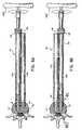
- these instrumentsinclude surgical drill 50, tap instrument 100, implant insertion instrument 150, fusion implant 200 and T-shaped handle 250 which is used to actuate each of the instruments.
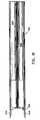
- Drill 50includes drill shaft 52, extension shaft 54 and drill bit 56 mounted at the distal end of the drill shaft 52.
- Extension shaft 54has first and second collars 58, 60 which cooperate to control the depth of penetration of drill shaft 52 and drill bit 56 into the adjacent vertebrae.
- Drill shaft 52includes a hexagonal-shaped head 62 at its proximal end to mount T-handle 250.
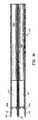
- Tap instrument 100is also disclosed in above-mentioned application. Tap instrument 100 is utilized for forming an internal thread within the drilled bore formed by the drill instrument 50. Tap instrument 100 includes elongated member 102 having hex head 104 at its proximal end to engage T-shaped handle 250. Tap instrument 100 further includes distal tapping threaded portion 106. Distal tapping portion 106 includes a plurality of conveyance channels (one is shown) 108 extending longitudinally through the cutting thread. Each conveyance channel 108 has a directional component parallel to the longitudinal axis and a directional component transverse to the longitudinal axis. Each conveyance channel 108 encompasses approximately an arc of about 1/3 the outer circumference of the tapping portion 106.
- Conveyance channels 108are each dimensioned to receive bone material deburred by the cutting edges during the tapping procedure and to continually transmit the bone material proximally through the channel to avoid undesired material build up at the tapping site. In this manner, tap instrument 100 may be used to completely tap the internal thread within the bore without interruption of the tapping procedure.
- Implant insertion instrument 150is configured for mounting and inserting fusion implant 200 within the intervertebral space.
- Insertion instrument 150includes elongated shaft 152 having hex-head mounting section 154 at its proximal end and cylindrical collar 156 at its distal end. Cylindrical collar 156 is dimensioned to be received within the cavity of fusion implant 200.
- a spring ball detent mechanism 158is disposed within cylindrical collar 156 to releasably engage implant 200.
- Detent mechanism 158is preferably spring-biased outwardly to engage corresponding structure defined within fusion implant 200 such as a recess or aperture formed in an interior wall thereof. Any type of detent mechanism 158 suitable for this intended purpose may be utilized.
- Collar 156may further include a pair of longitudinal grooves 160 which engage corresponding structure of implant 200 (e.g., inner longitudinal rails) to rotatably fix the implant on the collar, i.e., to prevent rotational movement of the implant 200 on the collar.
- implant 200e.g., inner longitudinal rails
- Other insertion instruments and arrangementsare also envisioned.
- Implant 200is uniquely designed for use in spinal fusion procedures. This implant 200 is generally disclosed in U.S. Patent No. 5,026,373 to Ray, and is commonly referred to as a "fusion cage". Implant or fusion cage 200 includes a cylindrical cage body 202 having an internal cavity or hole for accommodating bone-growth inducing substances. One end of cage body 202 is closed and defines a rounded or bull-nosed configuration to facilitate insertion of the fusion cage relative to one or more bony structures. The other end defines an opening which communicates with the internal cavity. The outer surface of the cage body 202 includes a single continuous thread (preferably V-shaped) having a plurality of raised turns with valleys defined between adjacent turns.
- a single continuous threadpreferably V-shaped
- a plurality of perforationsare disposed within the thread and extend through the outer surface of the cage body 202 to provide direct communication between the outer surface and internal cavity.
- the perforationspermit immediate contact between the bone growth inducing substances within the inner cavity and the bone structure when the cage body 202 is mated to the bone structure, e.g., adjacent vertebrae.
- An end cap(not shown) may be mountable to the open end of cage body 202 to enclose the bone-growth inducing substances within the interior cavity.
- T-shaped handle 250includes mounting portion 252 defining hexagonal-shaped recess 254 which receives the corresponding structure of drill instrument 50, tap instrument 100 and implant insertion instrument 150.
- FIG. 6which depicts a portion of the vertebral column
- a targeted intervertebral space "i" defined between adjacent vertebrae "V 1 , V 2 "is accessed utilizing appropriate retractors, e.g., laminal retractors, dural extractors.
- retractor head 22is placed on the proximal end of retractor sleeves 12a, 12b.
- Retractor 10is manipulated to align retractor arms 18 within the desired intervertebral space "i" defined between adjacent vertebrae "V 1 , V 2 ".
- retractor 10is arranged such that retractor sleeve 12a is adjacent a first lateral side "S 1 " of the intervertebral space "i” and retractor sleeve 12b is adjacent a second lateral side "S 2 " of the intervertebral space "i”.
- retractor arms 18are advanced into the intervertebral space "i" whereby first and second supporting surfaces 18a, 18b of each retractor arm 18 respectively engage the opposed vertebral bodies “V 1 , V 2 ".
- Retractor arms 18are preferably dimensioned to slightly distract the adjacent vertebrae “V 1 , V 2 ". However, alternatively, it is envisioned that retractor arms 18 may be configured to cause no distracting movement of the vertebrae “V 1 , V 2 ". Once inserted, retractor arms 18 effectively stabilize the adjacent vertebrae "V 1 , V 2 " across the span of the intervertebral space "i".
- retractor 10is driven distally, by e.g., impacting impactor head 22 with a standard mallet "m” as depicted in FIG. 7, which thereby drives retractor arms 18 within the adjacent vertebrae "V 1 , V 2 ". Tapered end portions 20 of retractor arms 18 facilitate advancement within the intervertebral space "i”.
- Drill 50is advanced into the intervertebral space "i" adjacent the first lateral side “S 1 " by rotating T-handle 250 such that drill bit 56 shears the soft tissue and cuts the bone of the adjacent vertebrae "V 1 , V 2 " thereby forming a bore which extends into the adjacent vertebrae "V 1 , V 2 ".
- Drill 50is then removed from retractor sleeve 12a. The drilling procedure is then repeated by insertion of drill instrument 50 within the second retractor sleeve 12b to form a bore within the adjacent vertebra "V 1 , V 2 " proximate the second lateral side "S 2 " as depicted in FIGS. 8B-8C.
- tap instrument 100is selected and attached to the T-handle 250.
- Tap instrument 100is inserted into first retractor sleeve 12a and positioned adjacent the drilled bore formed in the adjacent vertebrae "V 1 , V 2 " by the surgical drill 50.
- retractor sleeve 12aas a direct guide
- T-handle 250is rotated in the direction of the directional arrow of FIG. 9A while simultaneously applying sufficient downward pressure on the T-handle to advance the tap instrument 100 and promote even purchase into the endplates.
- the deburred bone chipscollect within conveyance channel 108 of tapping head 106, and are conveyed proximally during rotational movement of the tapping head 106 away from the tapping site.
- Tap instrument 100is advanced into the bone until the desired depth has been achieved, which occurs when the distal end of tapping head 108 "bottoms out” on the bone. When tap instrument 100 reaches the appropriate depth, the tap instrument 100 is rotated via T-handle 250 in an opposite direction to back the instrument out of the bore. The tapping procedure is then repeated by insertion of tap instrument 100 within the second retractor sleeve 12b to form a bore within the adjacent vertebrae "V 1 , V 2 " proximate the second lateral side as depicted in FIG. 9B. It is to be appreciated that in procedures where a self-tapping implant is utilized the tapping of the bores with tap instrument 100 is not necessary.
- FIG. 10shows a first fusion implant 10 already applied within the bore proximate the first lateral side "S 1 " of the intervertebral space i.
- cage body 202 of the fusion implant 200is mounted onto insertion instrument 150 by positioning the cage body 202 onto mounting collar 156 of the instrument to permit spring ball detent mechanism 158 to releasably engage corresponding structure of the implant body 202.
- This assemblyis attached to T-handle 250.
- Insertion instrument 150 with mounted cage body 202is inserted into retractor sleeve 12b of retractor 10 and the cage body 202 is positioned within the tapped bore by rotating insertion instrument 150 in the direction depicted in FIG. 10. Cage body 202 is advanced until it is completely seated with the bore as shown in FIG. 11. Insertion instrument 600 is then removed from retractor 100.
- bone growth inducing substancesmay be harvested from, e.g., the iliac crest, and packed into the cage body 202 of implant 200 until the cage body 202 is completely filled with bone growth inducing substances.
- An end capmay then be mounted to the cage body 202.
- Retractor 10is then removed. It is also contemplated that the implant could be at least partially packed with bone growth inducing substances prior to insertion.
- FIG. 12illustrates the two lateral fusion implants 200 inserted within the intervertebral space in accordance with the afore-described procedure.
- retractor 10 of the present disclosuremaintains a desired spacing between the adjacent vertebra "V 1 , V 2 " across the lateral span of the intervertebral space during the entire spinal fusion procedure to facilitate insertion of the two implants 200.
- the double sleeve arrangement 12a, 12badditional retracting movement of the adjacent vertebra "V 1 , V 2 " is not required for drilling/tapping procedures and during insertion of the pair of implants 200.
- the double sleeve arrangementensures optical alignment of each drilled bore and placement of the two fusion implants 200.
- the double sleeve arrangementalso reduces operating time since insertion of a separate retractor and/or distraction spacer is not required.
- FIGS. 13-15an alternate embodiment of the surgical retractor 10 of the present disclosure is illustrated.
- This retractoris similar to the retractor disclosed in connection with FIG. 1 except for the rib or spacer 24 between first and second retractor sleeves 12a, 12b.
- Rib 24, interposed between retractor sleeves 12a, 12b,is dimensioned to increase the lateral spacing of retractor sleeves 12a, 12b and arms 18.
- An increase in the lateral spacing of sleeves 12a, 12bmay be desirable to correspond to the size of the vertebrae targeted during the procedure.
- an increase in lateral spacingin effect, displaces the location of the pair of implants.
- connecting rib 24may extend for only a portion of the length of retractor 10.
- connecting rib 24may alternatively be provided as well.
- connecting rib 24is integrally formed with retractor sleeves 12a, 12b as a single monolithic unit although it is envisioned that the rib 24 may be a separate component connected to each sleeve 12a, 12b by welding, adhesives, etc...
- FIG. 16illustrates an alternate embodiment of the double surgical retractor of the present disclosure.
- Double retractor 10'is identical to retractor 10 of Figure 1 except that surfaces 70a, 70b of each retractor sleeve 12a', 12b' are curved to better conform to the curvature of the anterior aspect of the vertebral body.
- FIG. 17Another alternate embodiment of the surgical double retractor is illustrated in FIG. 17 and designated by reference numeral 80.
- Retractor 80has two sleeves 82a and 82b. It differs from the other embodiments in that each sleeve 82a, 82b has only one retractor arm 84a, 84b, respectively. That is, the two central adjacent arms are eliminated, thereby reducing the extent of the anterior ligament removed during retractor insertion.
- Retractor 80otherwise functions in the same manner as retractor 10 with each sleeve providing a cannula for insertion of the aforedescribed instrumentation and arms 84a, 84b providing vertebral distraction.
- retractor 80preferably has a concave surface 80b to complement the natural shape of the vertebral body.
Landscapes
- Health & Medical Sciences (AREA)
- Biomedical Technology (AREA)
- Engineering & Computer Science (AREA)
- Life Sciences & Earth Sciences (AREA)
- Orthopedic Medicine & Surgery (AREA)
- Veterinary Medicine (AREA)
- Animal Behavior & Ethology (AREA)
- Surgery (AREA)
- Public Health (AREA)
- Heart & Thoracic Surgery (AREA)
- General Health & Medical Sciences (AREA)
- Transplantation (AREA)
- Oral & Maxillofacial Surgery (AREA)
- Neurology (AREA)
- Molecular Biology (AREA)
- Medical Informatics (AREA)
- Nuclear Medicine, Radiotherapy & Molecular Imaging (AREA)
- Cardiology (AREA)
- Vascular Medicine (AREA)
- Dentistry (AREA)
- Physical Education & Sports Medicine (AREA)
- Prostheses (AREA)
- Surgical Instruments (AREA)
Description
- The present disclosure generally relates toinstrumentation for implant insertion and, in particular, to instrumentation forinsertion of a pair of spinal implants to facilitate fusion of adjacent vertebral bodies. The technical features of the pre-characterizing part of
claim 1 below are disclosed in combination in WO 96/27345. - A large number of orthopedic procedures involve the insertion of eithernatural or prosthetic implants into bone or associated tissues. These procedures include, forexample, ligament repair, joint repair or replacement, non-union fractures, facialreconstruction, spinal stabilization and spinal fusion. In a typical procedure, an insert,dowel or screw is inserted into a prepared bore formed in the bone or tissues to facilitaterepair and healing. See, for example, U.S. Patent Nos.: 5,470,334 to Ross et al.;5,454,811 to Huebner; 5,480,403 to Lee et al.; 5,358,511 to Gatturna et al.; and 4,877,020to Vich.
- Some implants are particularly configured with cavities and bores to facilitatebony ingrowth and enhance anchoring of the implant at the insertion site. See, for example,U.S. Patent Nos.: 4,328,593 to Sutter et al.; 4,936,851 to Fox et al.; and 4,878,915 toBrantigan. Other specialized implants include fusion cages having internal cavities toreceive bone growth stimulation materials such as bone chips and fragments. See, forexample, U.S. Patent Nos.: 4,501,269 to Bagby; 4,961,740 to Ray et al.; 5,015,247 toMichelson; and 5,489,307 to Kuslich et al. These types of implants are particularly wellsuited for intervertebral spinal fusion procedures necessitated by injury, disease or somedegenerative disorder of the spinal disc. Subsequently, there may be progressivedegeneration leading to mechanical instability between adjacent vertebrae necessitating directfusion of the vertebrae while maintaining a pre-defined intervertebral space. This fusionmay be accomplished by the insertion of one or more of the specialized implants as discussed above and also discussed U.S. Patent No. 5,026,373.
- Both anterior (transabdominal) and posterior surgical approaches are used forinterbody fusions of the lumbar spine. Fusions in the cervical area of the spine are primarilyperformed using posterior and anterior approaches as well. Typically, an implant such as aplug, dowel, prosthesis or cage is inserted into a preformed cavity inside the interbody,interdiscal space. Since it is desirable in these procedures to promote a "bone to bone"bridge, connective tissue and at least a portion of the distal tissue is removed. Preferably,relatively deep cuts are made in the adjacent bones in order to penetrate into the softer, morevascularized cancellous region to facilitate bone growth across the implant.
- One of the more critical tasks performed in the insertion of a surgical fusionimplant, particularly, in intervertebral spinal fusion, is the formation of the implant receivingcavity or bore within the adjacent vertebrae. More particularly, the drilled bore must beequally centered within the intervertebral space and preferably parallel to the vertebral endplates to ensure removal of equal portions of bone from the adjacent vertebrae throughoutthe length of the cut and subsequent appropriate seating of the implant relative to thevertebral bodies.
- Surgical instruments for facilitating spinal fusion implant insertion areknown. For example, U.S. Patent No. 5,484,437 to Michelson discloses a method andapparatus incorporating an outer and an inner sleeve arrangement. The outer sleeve has teethat one end which are driven directly into the posterior surface of the adjacent vertebrae. Theinner sleeve is positioned within the outer sleeve and serves to guide instruments such as adrill used to form the implant receiving bore. U.S. Patent Nos.: 5,487,307 to Kuslich etal.; 5,015,247 to Michelson; and 4,878,915 to Brantigan disclose similar arrangements.Other arrangements include the use of guide rods which are placed in pilot holes formed inthe vertebral bodies. The guide rods guide a bore forming hollow drill into the intervertebralspace.
- Although current instrumentation and methods associated therewith forenhancing the placement of spinal fusion implants have been generally effective for theirintended purposes, there exists certain limitations with the design of this instrumentation which detract from their usefulness. For example, the arrangement disclosed in theMichelson '437 patent and similar arrangements do not provide for automatic alignment ofthe outer sleeve to ensure that the bore formed by a drill introduced into the outer sleeve is inoptimal alignment for a tapping procedure (if required) and reception of the spinal implant.Rather, such orientation is dependent directly upon the skill of the surgeon. Moreover, theouter sleeve, which is mounted only at its extreme distal end to the posterior surface of theadjacent vertebrae, is subject to disorientation or dislodgment during insertion and/orremoval of the drill and/or tapping instrument. Similarly, the use of guide rods increases thenumber of steps required to implant the fusion cage and is also subject to possiblemisalignment.
- In many surgical implant techniques, two implants are inserted within theintervertebral space in side-by-side or lateral relation to fully support the adjacent vertebraeacross the span of the intervertebral space. In accordance with these techniques, a firstlateral side of the intervertebral space is prepared, e.g., by removing excess disc materialand drilling/tapping a bore to receive the implant followed by insertion of the implant.Thereafter, the second lateral side is prepared for implant insertion in the same manner.During the initial preparation of the first lateral side of the intervertebral space, however, theadjacent vertebrae are subjected to displacement in both the lateral and longitudinal direction.This may cause additional movement of the vertebral portion disposed on the other (second)lateral side of the intervertebral space.
- U.S. Patent No. 5,489,307 to Kuslich discloses a surgical method forimplanting two spinal implants into a disc space utilizing a distraction spacer which isinserted initially within one side of the intervertebral space. The rigid distraction spacer isintended to act against the vertebral end plates of the adjacent vertebrae to urge the vertebraeapart while the second side of the intervertebral space is prepared, by drilling/tapping, toreceive an implant. Once the implant is inserted, the distraction spacer is removed and theside left unoccupied by removal of the spacer is prepared to receive the second implant.
- The present disclosure is directed to a method and associated instrumentationto facilitate the introduction of at least two fusion implants, which maintains the desired disc height across the span of the intervertebral space and thereby ensures optimal alignment ofeach drilled bore for reception of the fusion implant.
- The invention is defined in
claim 1 below. Dependent claims are directed tooptimal or preferred features. - In one preferred embodiment, a surgical retractor instrument is disclosed.The retractor instrument includes at least two elongated members connected to each other inside by side relation. Each elongated member has proximal and distal end portions anddefines a longitudinal passageway for reception of surgical instrumentation. The distal endportion of each elongated member is configured for insertion at least partially within a spacedefined between adjacent tissue portions. Preferably, the distal end portion of eachelongated member includes at least one retractor arm extending in a general longitudinaldirection. Each retractor arm has first and second supporting surfaces for engaging opposedadjacent tissue portions, and defines a dimension between the first and second supportingsurfaces sufficient to distract the opposed tissue portions upon insertion thereof. The firstand second supporting surfaces of each retractor arm may be substantially planar. Theretractor arms may be dimensioned between the first and second supporting surfaces todistract adjacent vertebrae. In an alternate embodiment two spaced apart retractor armsextend from the distal end portion of each elongated member.
- In another preferred embodiment, a surgical retractor for use in distractingadjacent vertebrae includes first and second elongate sleeve members connected to eachother in side by side relation. Each sleeve member has a proximal end and a distal end anddefines a longitudinal passageway therebetween. At least two retractor arms extendlongitudinally from the distal end of the retractor. Each retractor arm defines a first vertebrasupporting surface and a second vertebra supporting surface portion. The first and secondvertebra supporting surfaces of each retractor arm are spaced thereon at a predetermineddistraction distance.
- In an alternate embodiment, a spacer member is disposed between the firstand second sleeve members to space the sleeve members at a predetermined distance.
- A method for performing a surgical procedure with the surgical retractorcan include the steps of providing a surgical retractor including at least two elongate members connected to each other along longitudinal portions thereof andhaving proximal and distal end portions with an opening therethrough to receiveinstrumentation, the distal end portion of each elongate member configured for insertion atleast partially into an intervertebral space between adjacent opposed vertebrae, inserting thedistal end of the two elongate members of the retractor to distract lateral sides of theintervertebral space and performing the surgical procedure adjacent the distracted vertebrae.The distal end portion of at the retractor may include two spaced apart retractor arms havingfirst and second supporting surfaces and wherein the step of distracting includes insertingthe retractor arms within the intervertebral space whereby the first and second supportingsurfaces of each retractor arm respectively engage the adjacent opposed vertebrae. Surgicalinstrumentation may be inserted within the opening of one of the elongate members toperform the surgical procedure. In a preferred embodiment, a fusion implant is insertedthrough the opening of the one elongate member and between the distracted vertebrae toeffect fusion thereof.
- Preferred embodiments of the disclosure are described hereinbelow withreference to the drawings wherein:
- FIG. 1 illustrates a double surgical retractor constructed in accordance withthe principles of the present disclosure and utilized in distracting adjacent bony structures,particularly adjacent vertebrae, and having first and second retractor sleeves;
- FIG. 2 is a top plan view of the double retractor of FIG. 1;
- FIG. 3 is a side plan view of the double retractor;
- FIG. 4 is a cross-sectional view of the double retractor taken along the lines4-4 of FIG. 3;
- FIG. 5 is a perspective view of a surgical kit for performing a spinal fusionprocedure illustrating, from bottom to top, the double retractor of FIG. 1, an implantinsertion apparatus, a surgical tap instrument, a drill instrument and a T-shaped handle;
- FIG. 6 is a view illustrating a portion of the vertebral column;
- FIG. 7 is a side view illustrating insertion of the double retractor of FIG. 1within an intervertebral space defined between adjacent vertebrae;
- FIG. 8A is a view of the intervertebral space taken along the
lines 8A-8A ofFIG. 6 illustrating insertion of the drill instrument through a first retractor sleeve of thedouble retractor to drill a bore adjacent a first lateral side of the adjacent vertebrae; - FIG. 8B is a view similar to the view of FIG. 8A illustrating insertion of thedrill instrument within the second retractor sleeve to drill a bore adjacent a second lateral sideof the adjacent vertebrae;
- FIG. 8C is a view taken along the
lines 8C-8C of FIG. 8B further illustratingadvancement of the drill instrument within the intervertebral space defined between adjacentvertebrae; - FIG. 9A is a view similar to the view of FIG. 8A illustrating insertion of thetap instrument within the first retractor sleeve for tapping the bore formed in the first lateralside of the adjacent vertebrae by the drill instrument;
- FIG. 9B is a view similar to the view of FIG. 9A illustrating insertion of thetap instrument within the second retractor sleeve for tapping the bore formed in the secondlateral side of the adjacent vertebrae by the drill instrument;
- FIG. 10 is a view similar to the view of FIG. 8A illustrating insertion of theimplant insertion instrument with mounted fusion implant within the retractor to mount theimplant within the tapped bore;
- FIG. 11 is a view taken along the lines 11-11 of FIG. 10 further illustratinginsertion of the implant insertion instrument within the intervertebral space defined betweenadjacent vertebrae;
- FIG. 12 is a cross-sectional view illustrating the insertion of two implantswithin the intervertebral space;
- FIG. 13 is a perspective view of an alternate embodiment of the doublesurgical retractor of FIG. 1 having a spacing member interposed between the retractorsleeves to laterally displace the two retractor sleeves;
- FIG. 14 is a top plan view of the double retractor of FIG. 13;
- FIG. 15 is a view of the double retractor of FIG. 13 taken along the lines 15-15of FIG. 14;
- FIG. 16 is a top plan view of another alternate embodiment of the doublesurgical retractor having a curved engagement surface;
- FIG. 17 is a perspective view of yet another alternate embodiment of thedouble surgical retractor having two retractor arms; and
- FIG. 18 is a top plan view of the double surgical retractor of FIG. 17.
- The preferred embodiments of the instrumentation disclosedherein are discussed in terms of orthopedic spinal fusion procedures and instrumentation. Itis also envisioned, however, that the disclosure is applicable to a wide variety of proceduresincluding, but, not limited to ligament repair, joint repair or replacement, non-unionfractures, facial reconstruction and spinal stabilization. In addition, it is believed that thepresent method and instrumentation finds application in both open and minimally invasiveprocedures including endoscopic and arthroscopic procedures wherein access to the surgicalsite is achieved through a cannula or small incision.
- The following discussion will include a description of each instrumentutilized in performing a spinal fusion method followed by a description of amethod for spinal fusion utilizing instrumentation that is accordance with the presentdisclosure.
- In the discussion which follows, the term "proximal", as is traditional, willrefer to the portion of the structure which is closest to the operator, while the term "distal"will refer to the portion which is furthest from the operator.
- Referring now to the drawings in which like reference numerals identifysimilar or identical elements throughout the several views, FIG. 1 illustrates in perspectiveview a preferred embodiment of the double surgical retractor of the present disclosure.
Double retractor 10 is particularly contemplated for distracting adjacent bony structures,e.g., adjacent vertebral bodies, to facilitate the insertion and application of a pair ofimplants. However, it is envisioned thatdouble retractor 10 may also be utilized to distract other structures as well including joints, ligaments, etc... Other applications forretractor 10are also contemplated. - Referring now to FIGS. 1-2,
double retractor 10 includes first andsecondretractor sleeves Retractor sleeves Retractor sleeves - Each
retractor sleeve sleeve retractor sleeve - With reference now to FIGS. 1-4, each
sleeve openings 14 formed in its outer wall.Openings 14 are diametrically arranged with relation to each other and terminate at theirdistal ends incircumferential collar 16. Eachopening 14 preferably extends radially forabout between 15%-40% the circumference or perimeter ofsleeve sleeve Openings 14 arecontemplated to permit the introduction of surgical instrumentation if necessary to assist incarrying out the fusion procedure. - Each
sleeve retractor arms 18.Retractor arms 18 extend distally fromcollar 16 in a general longitudinaldirection and are spaced from each other. Eacharm 18 has an arcuate outer surface (i.e.,defining a radius of curvature substantially equivalent to the radius of curvature of theremaining portion of the sleeve). Eachretractor arm 18 has first and second supportingsurfaces sleeve surfaces surfaces arm 18preferably ranges from about 7.1 mm to about 8.9 mm (about 0.28 to about 0.35 inches). Eacharm 18 further includestaperedend portions 20 defining a generally V-shaped configuration.End portions 20facilitate insertion ofretractor arms 18 within the surgical site, e.g., within the intervertebralspace. - As depicted in FIG. 5,
retractor 10 may further includeimpactor head 22which is correspondingly dimensioned to fit over the proximal ends ofretractor sleeves Impactor head 22 is dimensioned to slide ontoretractor 10 and form a friction fittherebetween.Impactor head 22 may further include an inner shelf which engages theproximal end faces ofretractor sleeves impactor head 22 maybe closed at its proximal end. - Referring still to FIG. 5, the various instruments utilized in performing adouble spinal fusion procedure with the
retractor 10 of the present disclosure are illustrated.These instruments includesurgical drill 50,tap instrument 100,implant insertion instrument 150,fusion implant 200 and T-shapedhandle 250 which is used to actuate each of theinstruments. Surgical drill 50 is disclosed in above-mentioned application.Drill 50 includesdrill shaft 52,extension shaft 54 anddrill bit 56 mounted at the distal endof thedrill shaft 52.Extension shaft 54 has first andsecond collars drill shaft 52 anddrill bit 56 into the adjacent vertebrae.Drill shaft 52 includes a hexagonal-shapedhead 62 at its proximal end to mount T-handle 250.Tap instrument 100 is also disclosed in above-mentioned application.Tap instrument 100 is utilized for forming an internal thread within the drilled bore formed by thedrillinstrument 50.Tap instrument 100 includeselongated member 102 havinghex head 104 atits proximal end to engage T-shapedhandle 250.Tap instrument 100 further includes distal tapping threadedportion 106.Distal tapping portion 106 includes a plurality of conveyancechannels (one is shown) 108 extending longitudinally through the cutting thread. Eachconveyance channel 108 has a directional component parallel to the longitudinal axis and adirectional component transverse to the longitudinal axis. Eachconveyance channel 108encompasses approximately an arc of about 1/3 the outer circumference of the tappingportion 106.Conveyance channels 108 are each dimensioned to receive bone materialdeburred by the cutting edges during the tapping procedure and to continually transmit thebone material proximally through the channel to avoid undesired material build up at thetapping site. In this manner,tap instrument 100 may be used to completely tap the internalthread within the bore without interruption of the tapping procedure.Implant insertion instrument 150 is configured for mounting and insertingfusion implant 200 within the intervertebral space.Insertion instrument 150 includeselongated shaft 152 having hex-head mounting section 154 at its proximal end andcylindrical collar 156 at its distal end.Cylindrical collar 156 is dimensioned to be receivedwithin the cavity offusion implant 200. A springball detent mechanism 158 is disposedwithincylindrical collar 156 to releasably engageimplant 200.Detent mechanism 158 ispreferably spring-biased outwardly to engage corresponding structure defined withinfusionimplant 200 such as a recess or aperture formed in an interior wall thereof. Any type ofdetent mechanism 158 suitable for this intended purpose may be utilized.Collar 156 mayfurther include a pair oflongitudinal grooves 160 which engage corresponding structure ofimplant 200 (e.g., inner longitudinal rails) to rotatably fix the implant on the collar, i.e., toprevent rotational movement of theimplant 200 on the collar. Other insertion instrumentsand arrangements are also envisioned.Implant 200 is uniquely designed for use in spinal fusion procedures. Thisimplant 200 is generally disclosed in U.S. Patent No. 5,026,373 to Ray,and is commonly referred toas a "fusion cage". Implant orfusion cage 200 includes acylindrical cage body 202 havingan internal cavity or hole for accommodating bone-growth inducing substances. One end ofcage body 202 is closed and defines a rounded or bull-nosed configuration to facilitateinsertion of the fusion cage relative to one or more bony structures. The other end defines an opening which communicates with the internal cavity. The outer surface of thecagebody 202 includes a single continuous thread (preferably V-shaped) having a plurality ofraised turns with valleys defined between adjacent turns.- A plurality of perforations are disposed within the thread and extend throughthe outer surface of the
cage body 202 to provide direct communication between the outersurface and internal cavity. The perforations permit immediate contact between the bonegrowth inducing substances within the inner cavity and the bone structure when thecagebody 202 is mated to the bone structure, e.g., adjacent vertebrae. An end cap (not shown)may be mountable to the open end ofcage body 202 to enclose the bone-growth inducingsubstances within the interior cavity. - T-shaped
handle 250 includes mounting portion 252 defining hexagonal-shapedrecess 254 which receives the corresponding structure ofdrill instrument 50,tapinstrument 100 andimplant insertion instrument 150. - The use of the instrumentation in conjunction with the insertion of a pair of
fusion implants 200 into an intervertebral space defined between adjacent vertebrae will bedescribed. The subsequent description will be particularly focused on an anterior procedurefor spinal surgery although a posterior approach is envisioned as well. - With reference to FIG. 6, which depicts a portion of the vertebral column, atargeted intervertebral space "i" defined between adjacent vertebrae "V1, V2" is accessedutilizing appropriate retractors, e.g., laminal retractors, dural extractors.
- As depicted in FIG. 7,
impactor head 22 is placed on the proximal end ofretractor sleeves Retractor 10 is manipulated to alignretractor arms 18 within thedesired intervertebral space "i" defined between adjacent vertebrae "V1, V2". Preferably,retractor 10 is arranged such thatretractor sleeve 12a is adjacent a first lateral side "S1" ofthe intervertebral space "i" andretractor sleeve 12b is adjacent a second lateral side "S2" ofthe intervertebral space "i". Thereafter,retractor arms 18 are advanced into the intervertebralspace "i" whereby first and second supportingsurfaces retractor arm 18respectively engage the opposed vertebral bodies "V1, V2".Retractor arms 18 are preferably dimensioned to slightly distract the adjacent vertebrae "V1, V2". However,alternatively, it is envisioned thatretractor arms 18 may be configured to cause nodistracting movement of the vertebrae "V1, V2". Once inserted,retractor arms 18effectively stabilize the adjacent vertebrae "V1, V2" across the span of the intervertebralspace "i". Preferably, during insertion,retractor 10 is driven distally, by e.g., impactingimpactor head 22 with a standard mallet "m" as depicted in FIG. 7, which thereby drivesretractor arms 18 within the adjacent vertebrae "V1, V2".Tapered end portions 20 ofretractor arms 18 facilitate advancement within the intervertebral space "i". - Referring now to FIG. 8A, with
retractor arms 18 ofretractor sleeves drill instrument 50 is adjusted as desired (i.e., to correspond to the length of the fusionimplant) by adjustingcollars handle 250 mounted to drillinstrument 50,the instrument is introduced into the axial bore ofretractor sleeves 12a and advanced tocontact the anterior surface of the vertebral bodies, "V1, V2".Drill 50 is advanced into theintervertebral space "i" adjacent the first lateral side "S1" by rotating T-handle 250 such thatdrill bit 56 shears the soft tissue and cuts the bone of the adjacent vertebrae "V1, V2"thereby forming a bore which extends into the adjacent vertebrae "V1, V2".Drill 50 is thenremoved fromretractor sleeve 12a. The drilling procedure is then repeated by insertion ofdrill instrument 50 within thesecond retractor sleeve 12b to form a bore within the adjacentvertebra "V1, V2" proximate the second lateral side "S2" as depicted in FIGS. 8B-8C. - Referring now to FIG. 9A,
tap instrument 100 is selected and attached to theT-handle 250.Tap instrument 100 is inserted intofirst retractor sleeve 12a and positionedadjacent the drilled bore formed in the adjacent vertebrae "V1, V2" by thesurgical drill 50.Withretractor sleeve 12a as a direct guide, T-handle 250 is rotated in the direction of thedirectional arrow of FIG. 9A while simultaneously applying sufficient downward pressureon the T-handle to advance thetap instrument 100 and promote even purchase into theendplates. Upon advancement of thetap instrument 100, the deburred bone chips collectwithinconveyance channel 108 of tappinghead 106, and are conveyed proximally duringrotational movement of the tappinghead 106 away from the tapping site.Tap instrument 100 is advanced into the bone until the desired depth has been achieved, which occurs whenthe distal end of tappinghead 108 "bottoms out" on the bone. Whentap instrument 100reaches the appropriate depth, thetap instrument 100 is rotated via T-handle 250 in anopposite direction to back the instrument out of the bore. The tapping procedure is thenrepeated by insertion oftap instrument 100 within thesecond retractor sleeve 12b to form abore within the adjacent vertebrae "V1, V2" proximate the second lateral side as depicted inFIG. 9B. It is to be appreciated that in procedures where a self-tapping implant is utilizedthe tapping of the bores withtap instrument 100 is not necessary. - With reference now to FIG. 10, attention is focused on the insertion of
fusion implant 200. FIG. 10 shows afirst fusion implant 10 already applied within the boreproximate the first lateral side "S1" of the intervertebral space i. To apply the fusionimplant,cage body 202 of thefusion implant 200 is mounted ontoinsertion instrument 150by positioning thecage body 202 onto mountingcollar 156 of the instrument to permitspringball detent mechanism 158 to releasably engage corresponding structure of theimplant body 202. This assembly is attached to T-handle 250.Insertion instrument 150with mountedcage body 202 is inserted intoretractor sleeve 12b ofretractor 10 and thecagebody 202 is positioned within the tapped bore by rotatinginsertion instrument 150 in thedirection depicted in FIG. 10.Cage body 202 is advanced until it is completely seated withthe bore as shown in FIG. 11. Insertion instrument 600 is then removed fromretractor 100. - At this point in the procedure, bone growth inducing substances may beharvested from, e.g., the iliac crest, and packed into the
cage body 202 ofimplant 200 untilthecage body 202 is completely filled with bone growth inducing substances. An end capmay then be mounted to thecage body 202.Retractor 10 is then removed. It is alsocontemplated that the implant could be at least partially packed with bone growth inducingsubstances prior to insertion. - FIG. 12 illustrates the two
lateral fusion implants 200 inserted within theintervertebral space in accordance with the afore-described procedure. - Thus,
retractor 10 of the present disclosure maintains a desired spacingbetween the adjacent vertebra "V1, V2" across the lateral span of the intervertebral space during the entire spinal fusion procedure to facilitate insertion of the twoimplants 200.With thedouble sleeve arrangement implants 200. Moreover, the double sleeve arrangement ensures optical alignment ofeach drilled bore and placement of the twofusion implants 200. The double sleevearrangement also reduces operating time since insertion of a separate retractor and/ordistraction spacer is not required. - Referring now to FIGS. 13-15, an alternate embodiment of the
surgicalretractor 10 of the present disclosure is illustrated. This retractor is similar to the retractordisclosed in connection with FIG. 1 except for the rib orspacer 24 between first andsecondretractor sleeves Rib 24, interposed betweenretractor sleeves retractor sleeves arms 18. Anincrease in the lateral spacing ofsleeves retractor sleeves rib 24 mayextend for only a portion of the length ofretractor 10. Several connectingribs 24 mayalternatively be provided as well. In a preferred embodiment, connectingrib 24 is integrallyformed withretractor sleeves rib 24 may be a separate component connected to eachsleeve - FIG. 16 illustrates an alternate embodiment of the double surgical retractor ofthe present disclosure. Double retractor 10' is identical to
retractor 10 of Figure 1 exceptthat surfaces 70a, 70b of eachretractor sleeve 12a', 12b' are curved to better conform to thecurvature of the anterior aspect of the vertebral body. - Another alternate embodiment of the surgical double retractor is illustrated inFIG. 17 and designated by
reference numeral 80.Retractor 80 has twosleeves 82a and82b. It differs from the other embodiments in that eachsleeve 82a, 82b has only oneretractor arm Retractor 80 otherwise functions in the same manner asretractor 10 with each sleeveproviding a cannula for insertion of the aforedescribed instrumentation andarms retractor 80 preferably has a concavesurface 80b to complement the natural shape of the vertebral body.
Claims (11)
- A surgical retractor (10) for use in distractingadjacent vertebrae (V19, V2) comprising two elongatesleeve members (12a, 12b) arranged in general parallel relation, each sleeve member having aproximal end and a distal end portion and defining alongitudinal passageway therebetween and at least oneretractor arm (18) extending longitudinally from thedistal end portion of each sleeve member; eachretractor arm defining a first vertebra-supportingsurface (18a) and a second vertebra-supporting surface(18b), the first and second vertebra-supporting surfacesof each retractor arm being spaced thereon at apredetermined distraction distance (h);
characterized in that:each sleeve member includes at least one longitudinalopening (14) defined in an intermediate wall portionthereof for reception of surgical instrumentation. - The surgical retractor according to claim 1 wherein thedistal end of each elongated sleeve member has tworetractor arms, each arm having distal tapered portionsfor facilitating insertion.
- The surgical retractor according to claim 1 or 2 whereinthe first and second supporting surfaces of eachretractor arm are in general parallel relation.
- The surgical retractor according to claim 3 wherein thefirst and second supporting surfaces of each retractor arm are in general parallel relation to the longitudinalaxis of the elongate sleeve.
- The surgical retractor according to any one of thepreceding claims wherein a distal surface of each sleevemember is concave.
- The surgical retractor according to anyone of thepreceding claims including a spacer member (24) disposedbetween the first and second sleeve members to increasethe distance between the sleeve members.
- The surgical retractor according to any one of thepreceding claims wherein the first and second sleevemembers are welded to each other.
- The surgical retractor according toclaims 1-6 wherein the first and second sleevemembers are monolithically formed.
- The surgical retractor as claimed in any one of thepreceding claims wherein each opening has a distal enddefined by a circumferential collar (16).
- The surgical retractor as claimed in any one of thepreceding claims wherein said opening extendslongitudinally for a distance which is 25 % of thelength of said sleeve member.
- The surgical retractor as claimed in any of thepreceding claims wherein said opening extends for adistance which is in a range of from 15 % to 40 % of thetotal circumference of the sleeve member.
Applications Claiming Priority (2)
| Application Number | Priority Date | Filing Date | Title |
|---|---|---|---|
| US4804597P | 1997-05-30 | 1997-05-30 | |
| US48045P | 1997-05-30 |
Publications (2)
| Publication Number | Publication Date |
|---|---|
| EP0880938A1 EP0880938A1 (en) | 1998-12-02 |
| EP0880938B1true EP0880938B1 (en) | 2003-12-10 |
Family
ID=21952451
Family Applications (1)
| Application Number | Title | Priority Date | Filing Date |
|---|---|---|---|
| EP98109238AExpired - LifetimeEP0880938B1 (en) | 1997-05-30 | 1998-05-20 | Instrumentation for implant insertion |
Country Status (5)
| Country | Link |
|---|---|
| EP (1) | EP0880938B1 (en) |
| JP (1) | JPH1147175A (en) |
| AU (1) | AU738696B2 (en) |
| CA (1) | CA2238117C (en) |
| DE (1) | DE69820338T2 (en) |
Cited By (32)
| Publication number | Priority date | Publication date | Assignee | Title |
|---|---|---|---|---|
| US6887248B2 (en) | 1998-05-27 | 2005-05-03 | Nuvasive, Inc. | Bone blocks and methods for inserting bone blocks into intervertebral spaces |
| US6923814B1 (en) | 2001-10-30 | 2005-08-02 | Nuvasive, Inc. | System and methods for cervical spinal fusion |
| USD530423S1 (en) | 2005-03-29 | 2006-10-17 | Nuvasive, Inc. | Intervertebral implant |
| US7544208B1 (en) | 2004-05-03 | 2009-06-09 | Theken Spine, Llc | Adjustable corpectomy apparatus |
| USD599019S1 (en) | 2008-03-07 | 2009-08-25 | Nuvasive, Inc. | Spinal fusion implant |
| US7618461B2 (en) | 2000-08-30 | 2009-11-17 | Warsaw Orthopedic, Inc. | Composite intervertebral disc implants and methods for forming the same |
| US7618423B1 (en) | 2002-06-15 | 2009-11-17 | Nuvasive, Inc. | System and method for performing spinal fusion |
| US7918876B2 (en) | 2003-03-24 | 2011-04-05 | Theken Spine, Llc | Spinal implant adjustment device |
| US8066750B2 (en) | 2006-10-06 | 2011-11-29 | Warsaw Orthopedic, Inc | Port structures for non-rigid bone plates |
| USRE43317E1 (en) | 2000-05-08 | 2012-04-17 | Depuy Spine, Inc. | Medical installation tool |
| US8187334B2 (en) | 2004-03-29 | 2012-05-29 | Nuvasive, Inc. | System and methods for spinal fusion |
| US8287597B1 (en) | 2009-04-16 | 2012-10-16 | Nuvasive, Inc. | Method and apparatus for performing spine surgery |
| US8328851B2 (en) | 2005-07-28 | 2012-12-11 | Nuvasive, Inc. | Total disc replacement system and related methods |
| US8377072B2 (en) | 2006-02-06 | 2013-02-19 | Depuy Spine, Inc. | Medical device installation tool |
| US8747476B2 (en) | 1999-03-07 | 2014-06-10 | Nuvasive, Inc. | Spinal implant system |
| USD721808S1 (en) | 2011-11-03 | 2015-01-27 | Nuvasive, Inc. | Intervertebral implant |
| US8945202B2 (en) | 2009-04-28 | 2015-02-03 | Endologix, Inc. | Fenestrated prosthesis |
| USD731063S1 (en) | 2009-10-13 | 2015-06-02 | Nuvasive, Inc. | Spinal fusion implant |
| USD735336S1 (en) | 2008-10-15 | 2015-07-28 | Nuvasive, Inc. | Intervertebral implant |
| US9101491B2 (en) | 2007-12-28 | 2015-08-11 | Nuvasive, Inc. | Spinal surgical implant and related methods |
| US9101484B2 (en) | 2000-07-17 | 2015-08-11 | Nuvasive, Inc. | Stackable spinal support system |
| USD741488S1 (en) | 2006-07-17 | 2015-10-20 | Nuvasive, Inc. | Spinal fusion implant |
| US9168152B2 (en) | 2008-02-29 | 2015-10-27 | Nuvasive, Inc. | Implants and methods for spinal fusion |
| US9186261B2 (en) | 2007-03-07 | 2015-11-17 | Nuvasive, Inc. | System and methods for spinal fusion |
| US9198765B1 (en) | 2011-10-31 | 2015-12-01 | Nuvasive, Inc. | Expandable spinal fusion implants and related methods |
| USD747485S1 (en) | 2011-11-03 | 2016-01-12 | Nuvasive, Inc. | Intervertebral implant |
| USD754346S1 (en) | 2009-03-02 | 2016-04-19 | Nuvasive, Inc. | Spinal fusion implant |
| US9351845B1 (en) | 2009-04-16 | 2016-05-31 | Nuvasive, Inc. | Method and apparatus for performing spine surgery |
| US9387090B2 (en) | 2009-03-12 | 2016-07-12 | Nuvasive, Inc. | Vertebral body replacement |
| US9566090B1 (en) | 2005-07-20 | 2017-02-14 | Nuvasive, Inc. | Systems and methods for treating spinal deformities |
| US12039731B2 (en) | 2020-12-22 | 2024-07-16 | Relievant Medsystems, Inc. | Prediction of candidates for spinal neuromodulation |
| US12433668B1 (en) | 2021-11-08 | 2025-10-07 | Relievant Medsystems, Inc. | Impedance stoppage mitigation during radiofrequency tissue ablation procedures |
Families Citing this family (48)
| Publication number | Priority date | Publication date | Assignee | Title |
|---|---|---|---|---|
| US6951572B1 (en) | 1997-02-20 | 2005-10-04 | Endologix, Inc. | Bifurcated vascular graft and method and apparatus for deploying same |
| US6290724B1 (en) | 1998-05-27 | 2001-09-18 | Nuvasive, Inc. | Methods for separating and stabilizing adjacent vertebrae |
| US6251140B1 (en) | 1998-05-27 | 2001-06-26 | Nuvasive, Inc. | Interlocking spinal inserts |
| US6648895B2 (en) | 2000-02-04 | 2003-11-18 | Sdgi Holdings, Inc. | Methods and instrumentation for vertebral interbody fusion |
| US6743234B2 (en) | 1999-02-04 | 2004-06-01 | Sdgi Holdings, Inc. | Methods and instrumentation for vertebral interbody fusion |
| AU2003234872B2 (en)* | 1999-02-04 | 2005-01-06 | Warsaw Orthopedic, Inc. | Methods and Instrumentation for Vertebral Interbody Fusion |
| AU761818C (en)* | 1999-02-04 | 2004-05-27 | Warsaw Orthopedic, Inc. | Methods and instrumentation for vertebral interbody fusion |
| AU2005201167B2 (en)* | 1999-02-04 | 2006-06-22 | Warsaw Orthopedic, Inc. | Methods and instrumentation for vertebral interbody fusion |
| CA2366824C (en)* | 1999-04-07 | 2008-03-18 | Surgical Dynamics, Inc. | Low profile fusion cage and insertion set |
| DE60030989T2 (en) | 1999-08-26 | 2007-05-24 | Warsaw Orthopedic, Inc., Warsaw | DEVICE FOR IMPLANTING FUSION CAGE |
| US6447512B1 (en)* | 2000-01-06 | 2002-09-10 | Spinal Concepts, Inc. | Instrument and method for implanting an interbody fusion device |
| EP1255500B1 (en)* | 2000-02-03 | 2007-05-30 | Baylor College of Medicine | Devices for intraosseous nerve ablation |
| US6514260B1 (en)* | 2000-03-15 | 2003-02-04 | Sdgi Holdings, Inc. | Methods and instruments for laparoscopic spinal surgery |
| US6342057B1 (en) | 2000-04-28 | 2002-01-29 | Synthes (Usa) | Remotely aligned surgical drill guide |
| US6379364B1 (en) | 2000-04-28 | 2002-04-30 | Synthes (Usa) | Dual drill guide for a locking bone plate |
| US7018416B2 (en) | 2000-07-06 | 2006-03-28 | Zimmer Spine, Inc. | Bone implants and methods |
| US6641582B1 (en) | 2000-07-06 | 2003-11-04 | Sulzer Spine-Tech Inc. | Bone preparation instruments and methods |
| WO2002003867A2 (en)* | 2000-07-06 | 2002-01-17 | Sulzer Spine-Tech Inc. | Bone preparation instruments |
| US7204851B2 (en) | 2000-08-30 | 2007-04-17 | Sdgi Holdings, Inc. | Method and apparatus for delivering an intervertebral disc implant |
| US20020026244A1 (en) | 2000-08-30 | 2002-02-28 | Trieu Hai H. | Intervertebral disc nucleus implants and methods |
| US7503936B2 (en)* | 2000-08-30 | 2009-03-17 | Warsaw Orthopedic, Inc. | Methods for forming and retaining intervertebral disc implants |
| US8361067B2 (en) | 2002-09-30 | 2013-01-29 | Relievant Medsystems, Inc. | Methods of therapeutically heating a vertebral body to treat back pain |
| US6907884B2 (en) | 2002-09-30 | 2005-06-21 | Depay Acromed, Inc. | Method of straddling an intraosseous nerve |
| US7258690B2 (en) | 2003-03-28 | 2007-08-21 | Relievant Medsystems, Inc. | Windowed thermal ablation probe |
| WO2004105656A1 (en)* | 2003-05-27 | 2004-12-09 | Pentax Corporation | Surgical instrument |
| US7575580B2 (en)* | 2005-04-15 | 2009-08-18 | Warsaw Orthopedic, Inc. | Instruments, implants and methods for positioning implants into a spinal disc space |
| AU2007280012B2 (en) | 2006-07-31 | 2013-01-31 | T.A.G. Medical Devices - Agriculture Cooperative Ltd. | Arthroscopic bone transplanting procedure, and medical instruments useful therein |
| EP2157924B1 (en) | 2007-05-30 | 2019-11-06 | T.A.G. Medical Devices - Agriculture Cooperative Ltd. | Piercing implement particularly useful as a medical implement for piercing body tissue |
| WO2009105699A1 (en) | 2008-02-22 | 2009-08-27 | Endologix, Inc. | Design and method of placement of a graft or graft system |
| US8236040B2 (en) | 2008-04-11 | 2012-08-07 | Endologix, Inc. | Bifurcated graft deployment systems and methods |
| EP2520320B1 (en) | 2008-07-01 | 2016-11-02 | Endologix, Inc. | Catheter system |
| US10028753B2 (en) | 2008-09-26 | 2018-07-24 | Relievant Medsystems, Inc. | Spine treatment kits |
| CA2737374C (en) | 2008-09-26 | 2017-03-28 | Relievant Medsystems, Inc. | Systems and methods for navigating an instrument through bone |
| US9687357B2 (en) | 2009-03-12 | 2017-06-27 | Nuvasive, Inc. | Vertebral body replacement |
| US20120109279A1 (en) | 2010-11-02 | 2012-05-03 | Endologix, Inc. | Apparatus and method of placement of a graft or graft system |
| US8808350B2 (en) | 2011-03-01 | 2014-08-19 | Endologix, Inc. | Catheter system and methods of using same |
| AU2012362524B2 (en) | 2011-12-30 | 2018-12-13 | Relievant Medsystems, Inc. | Systems and methods for treating back pain |
| US10588691B2 (en) | 2012-09-12 | 2020-03-17 | Relievant Medsystems, Inc. | Radiofrequency ablation of tissue within a vertebral body |
| WO2014071161A1 (en) | 2012-11-05 | 2014-05-08 | Relievant Medsystems, Inc. | System and methods for creating curved paths through bone and modulating nerves within the bone |
| US9724151B2 (en) | 2013-08-08 | 2017-08-08 | Relievant Medsystems, Inc. | Modulating nerves within bone using bone fasteners |
| USD745159S1 (en) | 2013-10-10 | 2015-12-08 | Nuvasive, Inc. | Intervertebral implant |
| US10478313B1 (en) | 2014-01-10 | 2019-11-19 | Nuvasive, Inc. | Spinal fusion implant and related methods |
| USD858769S1 (en) | 2014-11-20 | 2019-09-03 | Nuvasive, Inc. | Intervertebral implant |
| WO2017004265A1 (en) | 2015-06-30 | 2017-01-05 | Endologix, Inc. | Locking assembly for coupling guidewire to delivery system |
| AU2020346827A1 (en) | 2019-09-12 | 2022-03-31 | Relievant Medsystems, Inc. | Systems and methods for tissue modulation |
| US12082876B1 (en) | 2020-09-28 | 2024-09-10 | Relievant Medsystems, Inc. | Introducer drill |
| CN117224293B (en)* | 2023-11-14 | 2024-01-23 | 苏州大学附属第二医院 | Transverse guiding implantation tool of interbody fusion cage |
| CN118370569B (en)* | 2024-06-21 | 2024-08-30 | 北京市顺义区妇幼保健院 | Tapping device suitable for minimally invasive surgery |
Family Cites Families (14)
| Publication number | Priority date | Publication date | Assignee | Title |
|---|---|---|---|---|
| US557109A (en)* | 1896-03-31 | David cociirane | ||
| CH642250A5 (en) | 1979-12-22 | 1984-04-13 | Straumann Inst Ag | BALL JOINT PROSTHESIS WITH A CAP. |
| US4501269A (en) | 1981-12-11 | 1985-02-26 | Washington State University Research Foundation, Inc. | Process for fusing bone joints |
| US4877020A (en) | 1984-11-30 | 1989-10-31 | Vich Jose M O | Apparatus for bone graft |
| US4834757A (en) | 1987-01-22 | 1989-05-30 | Brantigan John W | Prosthetic implant |
| US4898156A (en) | 1987-05-18 | 1990-02-06 | Mitek Surgical Products, Inc. | Suture anchor |
| EP0703757B1 (en)* | 1988-06-13 | 2003-08-27 | Karlin Technology, Inc. | Apparatus for inserting spinal implants |
| US4936851A (en) | 1988-08-26 | 1990-06-26 | Colin Electronics Co., Ltd. | Analytic bone implant |
| CA2062012C (en) | 1991-03-05 | 2003-04-29 | Randall D. Ross | Bioabsorbable interference bone fixation screw |
| US5480403A (en) | 1991-03-22 | 1996-01-02 | United States Surgical Corporation | Suture anchoring device and method |
| US5250055A (en)* | 1992-06-08 | 1993-10-05 | Orthopedic Systems Inc. | Method and apparatus for tying suture to bone |
| DE4328690B4 (en)* | 1993-08-26 | 2006-08-17 | SDGI Holdings, Inc., Wilmington | Intervertebral implant for vertebral body blocking and implantation instrument for positioning the intervertebral implant |
| US5454811A (en) | 1993-11-08 | 1995-10-03 | Smith & Nephew Dyonics, Inc. | Cam lock orthopedic fixation screw and method |
| CA2199462C (en)* | 1996-03-14 | 2006-01-03 | Charles J. Winslow | Method and instrumentation for implant insertion |
- 1998
- 1998-05-14CACA002238117Apatent/CA2238117C/ennot_activeExpired - Fee Related
- 1998-05-20EPEP98109238Apatent/EP0880938B1/ennot_activeExpired - Lifetime
- 1998-05-20DEDE69820338Tpatent/DE69820338T2/ennot_activeExpired - Lifetime
- 1998-05-29AUAU69789/98Apatent/AU738696B2/ennot_activeCeased
- 1998-06-01JPJP10150892Apatent/JPH1147175A/enactivePending
Cited By (51)
| Publication number | Priority date | Publication date | Assignee | Title |
|---|---|---|---|---|
| US6887248B2 (en) | 1998-05-27 | 2005-05-03 | Nuvasive, Inc. | Bone blocks and methods for inserting bone blocks into intervertebral spaces |
| US8747476B2 (en) | 1999-03-07 | 2014-06-10 | Nuvasive, Inc. | Spinal implant system |
| US9398962B2 (en) | 1999-03-07 | 2016-07-26 | Nuvasive, Inc. | Spinal implant system |
| USRE43317E1 (en) | 2000-05-08 | 2012-04-17 | Depuy Spine, Inc. | Medical installation tool |
| USRE44835E1 (en) | 2000-05-08 | 2014-04-08 | Depuy Synthes Products Llc | Medical installation tool |
| USRE45639E1 (en) | 2000-05-08 | 2015-08-04 | DePuy Synthes Products, Inc. | Medical installation tool |
| US9101484B2 (en) | 2000-07-17 | 2015-08-11 | Nuvasive, Inc. | Stackable spinal support system |
| US7618461B2 (en) | 2000-08-30 | 2009-11-17 | Warsaw Orthopedic, Inc. | Composite intervertebral disc implants and methods for forming the same |
| US6923814B1 (en) | 2001-10-30 | 2005-08-02 | Nuvasive, Inc. | System and methods for cervical spinal fusion |
| US7618423B1 (en) | 2002-06-15 | 2009-11-17 | Nuvasive, Inc. | System and method for performing spinal fusion |
| US7918876B2 (en) | 2003-03-24 | 2011-04-05 | Theken Spine, Llc | Spinal implant adjustment device |
| US8187334B2 (en) | 2004-03-29 | 2012-05-29 | Nuvasive, Inc. | System and methods for spinal fusion |
| US9474627B2 (en) | 2004-03-29 | 2016-10-25 | Nuvasive, Inc. | Systems and methods for spinal fusion |
| US9180021B2 (en) | 2004-03-29 | 2015-11-10 | Nuvasive, Inc. | Systems and methods for spinal fusion |
| US7544208B1 (en) | 2004-05-03 | 2009-06-09 | Theken Spine, Llc | Adjustable corpectomy apparatus |
| USD594986S1 (en) | 2005-03-29 | 2009-06-23 | Nuvasive, Inc. | Intervertebral implant |
| USD530423S1 (en) | 2005-03-29 | 2006-10-17 | Nuvasive, Inc. | Intervertebral implant |
| US9566090B1 (en) | 2005-07-20 | 2017-02-14 | Nuvasive, Inc. | Systems and methods for treating spinal deformities |
| US8328851B2 (en) | 2005-07-28 | 2012-12-11 | Nuvasive, Inc. | Total disc replacement system and related methods |
| US9168149B2 (en) | 2005-07-28 | 2015-10-27 | NaVasive, Inc. | Total disc replacement system and related methods |
| US8870960B2 (en) | 2005-07-28 | 2014-10-28 | Nuvasive, Inc. | Total disc replacement system and related methods |
| US8377072B2 (en) | 2006-02-06 | 2013-02-19 | Depuy Spine, Inc. | Medical device installation tool |
| USD741488S1 (en) | 2006-07-17 | 2015-10-20 | Nuvasive, Inc. | Spinal fusion implant |
| US8066750B2 (en) | 2006-10-06 | 2011-11-29 | Warsaw Orthopedic, Inc | Port structures for non-rigid bone plates |
| US9486329B2 (en) | 2007-03-07 | 2016-11-08 | Nuvasive, Inc. | System and methods for spinal fusion |
| US9186261B2 (en) | 2007-03-07 | 2015-11-17 | Nuvasive, Inc. | System and methods for spinal fusion |
| US9101491B2 (en) | 2007-12-28 | 2015-08-11 | Nuvasive, Inc. | Spinal surgical implant and related methods |
| US9168152B2 (en) | 2008-02-29 | 2015-10-27 | Nuvasive, Inc. | Implants and methods for spinal fusion |
| USD599019S1 (en) | 2008-03-07 | 2009-08-25 | Nuvasive, Inc. | Spinal fusion implant |
| USD781423S1 (en) | 2008-10-15 | 2017-03-14 | Nuvasive, Inc. | Intervertebral implant |
| USD735336S1 (en) | 2008-10-15 | 2015-07-28 | Nuvasive, Inc. | Intervertebral implant |
| USD750252S1 (en) | 2008-10-15 | 2016-02-23 | Nuvasive, Inc. | Intervertebral implant |
| USD754346S1 (en) | 2009-03-02 | 2016-04-19 | Nuvasive, Inc. | Spinal fusion implant |
| USD797934S1 (en) | 2009-03-02 | 2017-09-19 | Nuvasive, Inc. | Spinal fusion implant |
| US9387090B2 (en) | 2009-03-12 | 2016-07-12 | Nuvasive, Inc. | Vertebral body replacement |
| US9351845B1 (en) | 2009-04-16 | 2016-05-31 | Nuvasive, Inc. | Method and apparatus for performing spine surgery |
| US8920500B1 (en) | 2009-04-16 | 2014-12-30 | Nuvasive, Inc. | Methods and apparatus for performing spine surgery |
| US8287597B1 (en) | 2009-04-16 | 2012-10-16 | Nuvasive, Inc. | Method and apparatus for performing spine surgery |
| US9192482B1 (en) | 2009-04-16 | 2015-11-24 | Nuvasive, Inc. | Methods and apparatus for performing spine surgery |
| US10603196B2 (en) | 2009-04-28 | 2020-03-31 | Endologix, Inc. | Fenestrated prosthesis |
| US8945202B2 (en) | 2009-04-28 | 2015-02-03 | Endologix, Inc. | Fenestrated prosthesis |
| USD731063S1 (en) | 2009-10-13 | 2015-06-02 | Nuvasive, Inc. | Spinal fusion implant |
| US9198765B1 (en) | 2011-10-31 | 2015-12-01 | Nuvasive, Inc. | Expandable spinal fusion implants and related methods |
| USD767762S1 (en) | 2011-11-03 | 2016-09-27 | Nuvasive, Inc. | Intervertebral implant |
| USD721808S1 (en) | 2011-11-03 | 2015-01-27 | Nuvasive, Inc. | Intervertebral implant |
| USD788307S1 (en) | 2011-11-03 | 2017-05-30 | Nuvasive, Inc. | Intervertebral implant |
| USD791949S1 (en) | 2011-11-03 | 2017-07-11 | Nuvasive, Inc. | Intervertebral implant |
| USD759248S1 (en) | 2011-11-03 | 2016-06-14 | Nuvasive, Inc. | Intervertebral implant |
| USD747485S1 (en) | 2011-11-03 | 2016-01-12 | Nuvasive, Inc. | Intervertebral implant |
| US12039731B2 (en) | 2020-12-22 | 2024-07-16 | Relievant Medsystems, Inc. | Prediction of candidates for spinal neuromodulation |
| US12433668B1 (en) | 2021-11-08 | 2025-10-07 | Relievant Medsystems, Inc. | Impedance stoppage mitigation during radiofrequency tissue ablation procedures |
Also Published As
| Publication number | Publication date |
|---|---|
| CA2238117A1 (en) | 1998-11-30 |
| DE69820338D1 (en) | 2004-01-22 |
| JPH1147175A (en) | 1999-02-23 |
| AU6978998A (en) | 1998-12-03 |
| EP0880938A1 (en) | 1998-12-02 |
| AU738696B2 (en) | 2001-09-27 |
| CA2238117C (en) | 2006-01-10 |
| DE69820338T2 (en) | 2004-10-07 |
Similar Documents
| Publication | Publication Date | Title |
|---|---|---|
| EP0880938B1 (en) | Instrumentation for implant insertion | |
| US6267763B1 (en) | Method and apparatus for spinal implant insertion | |
| US6083225A (en) | Method and instrumentation for implant insertion | |
| US6042582A (en) | Instrumentation and method for facilitating insertion of spinal implant | |
| US20020143343A1 (en) | Method and apparatus for spinal implant insertion | |
| EP1006955B1 (en) | Apparatus for fusing adjacent bone structures | |
| US6540753B2 (en) | Instrumentation for implant insertion | |
| US6063088A (en) | Method and instrumentation for implant insertion | |
| US6929647B2 (en) | Instrumentation and method for implant insertion | |
| US5968098A (en) | Apparatus for fusing adjacent bone structures | |
| US6582437B2 (en) | Devices and methods for implanting fusion cages | |
| US6210412B1 (en) | Method for inserting frusto-conical interbody spinal fusion implants | |
| EP1207792B1 (en) | Minimal exposure posterior spinal interbody instrumentation | |
| US7291149B1 (en) | Method for inserting interbody spinal fusion implants | |
| US20040098129A1 (en) | Spinal implant insertion adjustment instrument and implants for use therewith | |
| AU765839B2 (en) | Method and instrumentation for implant insertion |
Legal Events
| Date | Code | Title | Description |
|---|---|---|---|
| PUAI | Public reference made under article 153(3) epc to a published international application that has entered the european phase | Free format text:ORIGINAL CODE: 0009012 | |
| AK | Designated contracting states | Kind code of ref document:A1 Designated state(s):DE ES FR GB IT NL | |
| AX | Request for extension of the european patent | Free format text:AL;LT;LV;MK;RO;SI | |
| 17P | Request for examination filed | Effective date:19990121 | |
| AKX | Designation fees paid | Free format text:DE ES FR GB IT | |
| RBV | Designated contracting states (corrected) | Designated state(s):DE ES FR GB IT NL | |
| 17Q | First examination report despatched | Effective date:20020621 | |
| GRAH | Despatch of communication of intention to grant a patent | Free format text:ORIGINAL CODE: EPIDOS IGRA | |
| RAP1 | Party data changed (applicant data changed or rights of an application transferred) | Owner name:HOWMEDICA OSTEONICS CORP. | |
| GRAS | Grant fee paid | Free format text:ORIGINAL CODE: EPIDOSNIGR3 | |
| GRAA | (expected) grant | Free format text:ORIGINAL CODE: 0009210 | |
| AK | Designated contracting states | Kind code of ref document:B1 Designated state(s):DE ES FR GB IT NL | |
| PG25 | Lapsed in a contracting state [announced via postgrant information from national office to epo] | Ref country code:NL Free format text:LAPSE BECAUSE OF FAILURE TO SUBMIT A TRANSLATION OF THE DESCRIPTION OR TO PAY THE FEE WITHIN THE PRESCRIBED TIME-LIMIT Effective date:20031210 | |
| REG | Reference to a national code | Ref country code:GB Ref legal event code:FG4D | |
| REF | Corresponds to: | Ref document number:69820338 Country of ref document:DE Date of ref document:20040122 Kind code of ref document:P | |
| PG25 | Lapsed in a contracting state [announced via postgrant information from national office to epo] | Ref country code:ES Free format text:LAPSE BECAUSE OF FAILURE TO SUBMIT A TRANSLATION OF THE DESCRIPTION OR TO PAY THE FEE WITHIN THE PRESCRIBED TIME-LIMIT Effective date:20040321 | |
| RAP2 | Party data changed (patent owner data changed or rights of a patent transferred) | Owner name:HOWMEDICA OSTEONICS CORP. | |
| NLV1 | Nl: lapsed or annulled due to failure to fulfill the requirements of art. 29p and 29m of the patents act | ||
| ET | Fr: translation filed | ||
| PLBE | No opposition filed within time limit | Free format text:ORIGINAL CODE: 0009261 | |
| STAA | Information on the status of an ep patent application or granted ep patent | Free format text:STATUS: NO OPPOSITION FILED WITHIN TIME LIMIT | |
| 26N | No opposition filed | Effective date:20040913 | |
| PGFP | Annual fee paid to national office [announced via postgrant information from national office to epo] | Ref country code:IT Payment date:20070519 Year of fee payment:10 | |
| PG25 | Lapsed in a contracting state [announced via postgrant information from national office to epo] | Ref country code:IT Free format text:LAPSE BECAUSE OF NON-PAYMENT OF DUE FEES Effective date:20080520 | |
| PGFP | Annual fee paid to national office [announced via postgrant information from national office to epo] | Ref country code:GB Payment date:20140425 Year of fee payment:17 | |
| PGFP | Annual fee paid to national office [announced via postgrant information from national office to epo] | Ref country code:FR Payment date:20140424 Year of fee payment:17 Ref country code:DE Payment date:20140602 Year of fee payment:17 | |
| REG | Reference to a national code | Ref country code:DE Ref legal event code:R119 Ref document number:69820338 Country of ref document:DE | |
| GBPC | Gb: european patent ceased through non-payment of renewal fee | Effective date:20150520 | |
| REG | Reference to a national code | Ref country code:FR Ref legal event code:ST Effective date:20160129 | |
| PG25 | Lapsed in a contracting state [announced via postgrant information from national office to epo] | Ref country code:DE Free format text:LAPSE BECAUSE OF NON-PAYMENT OF DUE FEES Effective date:20151201 Ref country code:GB Free format text:LAPSE BECAUSE OF NON-PAYMENT OF DUE FEES Effective date:20150520 | |
| PG25 | Lapsed in a contracting state [announced via postgrant information from national office to epo] | Ref country code:FR Free format text:LAPSE BECAUSE OF NON-PAYMENT OF DUE FEES Effective date:20150601 |