EP0880220A2 - A phase staggered full-bridge converter with soft-PWM switching - Google Patents
A phase staggered full-bridge converter with soft-PWM switchingDownload PDFInfo
- Publication number
- EP0880220A2 EP0880220A2EP98107215AEP98107215AEP0880220A2EP 0880220 A2EP0880220 A2EP 0880220A2EP 98107215 AEP98107215 AEP 98107215AEP 98107215 AEP98107215 AEP 98107215AEP 0880220 A2EP0880220 A2EP 0880220A2
- Authority
- EP
- European Patent Office
- Prior art keywords
- switching
- converter
- control circuit
- switching devices
- voltage
- Prior art date
- Legal status (The legal status is an assumption and is not a legal conclusion. Google has not performed a legal analysis and makes no representation as to the accuracy of the status listed.)
- Granted
Links
- 238000012546transferMethods0.000claimsabstractdescription39
- 230000007704transitionEffects0.000claimsabstractdescription31
- 230000003071parasitic effectEffects0.000claimsabstractdescription19
- 238000004804windingMethods0.000claimsdescription70
- 239000003990capacitorSubstances0.000claimsdescription19
- 238000011084recoveryMethods0.000claimsdescription14
- 230000000903blocking effectEffects0.000claimsdescription8
- 229920006395saturated elastomerPolymers0.000claimsdescription3
- 230000007423decreaseEffects0.000claimsdescription2
- 230000001939inductive effectEffects0.000claimsdescription2
- 230000000977initiatory effectEffects0.000claims3
- 230000008878couplingEffects0.000claims1
- 238000010168coupling processMethods0.000claims1
- 238000005859coupling reactionMethods0.000claims1
- 230000001747exhibiting effectEffects0.000claims1
- 238000001914filtrationMethods0.000claims1
- 238000009499grossingMethods0.000claims1
- 230000001502supplementing effectEffects0.000claims1
- 230000000694effectsEffects0.000abstractdescription4
- 230000010363phase shiftEffects0.000description9
- 238000013459approachMethods0.000description6
- 238000000034methodMethods0.000description5
- 230000008859changeEffects0.000description3
- 230000008901benefitEffects0.000description2
- 230000001965increasing effectEffects0.000description2
- 238000012986modificationMethods0.000description2
- 230000004048modificationEffects0.000description2
- 230000008569processEffects0.000description2
- 230000033228biological regulationEffects0.000description1
- 230000002950deficientEffects0.000description1
- 230000001934delayEffects0.000description1
- 238000010586diagramMethods0.000description1
- 230000009977dual effectEffects0.000description1
- 230000005672electromagnetic fieldEffects0.000description1
- 230000005669field effectEffects0.000description1
- 238000005259measurementMethods0.000description1
- 229910044991metal oxideInorganic materials0.000description1
- 150000004706metal oxidesChemical class0.000description1
- 230000009467reductionEffects0.000description1
- 239000004065semiconductorSubstances0.000description1
Images


Classifications
- H—ELECTRICITY
- H02—GENERATION; CONVERSION OR DISTRIBUTION OF ELECTRIC POWER
- H02M—APPARATUS FOR CONVERSION BETWEEN AC AND AC, BETWEEN AC AND DC, OR BETWEEN DC AND DC, AND FOR USE WITH MAINS OR SIMILAR POWER SUPPLY SYSTEMS; CONVERSION OF DC OR AC INPUT POWER INTO SURGE OUTPUT POWER; CONTROL OR REGULATION THEREOF
- H02M3/00—Conversion of DC power input into DC power output
- H02M3/22—Conversion of DC power input into DC power output with intermediate conversion into AC
- H02M3/24—Conversion of DC power input into DC power output with intermediate conversion into AC by static converters
- H02M3/28—Conversion of DC power input into DC power output with intermediate conversion into AC by static converters using discharge tubes with control electrode or semiconductor devices with control electrode to produce the intermediate AC
- H02M3/325—Conversion of DC power input into DC power output with intermediate conversion into AC by static converters using discharge tubes with control electrode or semiconductor devices with control electrode to produce the intermediate AC using devices of a triode or a transistor type requiring continuous application of a control signal
- H02M3/335—Conversion of DC power input into DC power output with intermediate conversion into AC by static converters using discharge tubes with control electrode or semiconductor devices with control electrode to produce the intermediate AC using devices of a triode or a transistor type requiring continuous application of a control signal using semiconductor devices only
- H02M3/337—Conversion of DC power input into DC power output with intermediate conversion into AC by static converters using discharge tubes with control electrode or semiconductor devices with control electrode to produce the intermediate AC using devices of a triode or a transistor type requiring continuous application of a control signal using semiconductor devices only in push-pull configuration
- H02M3/3376—Conversion of DC power input into DC power output with intermediate conversion into AC by static converters using discharge tubes with control electrode or semiconductor devices with control electrode to produce the intermediate AC using devices of a triode or a transistor type requiring continuous application of a control signal using semiconductor devices only in push-pull configuration with automatic control of output voltage or current
- H—ELECTRICITY
- H02—GENERATION; CONVERSION OR DISTRIBUTION OF ELECTRIC POWER
- H02M—APPARATUS FOR CONVERSION BETWEEN AC AND AC, BETWEEN AC AND DC, OR BETWEEN DC AND DC, AND FOR USE WITH MAINS OR SIMILAR POWER SUPPLY SYSTEMS; CONVERSION OF DC OR AC INPUT POWER INTO SURGE OUTPUT POWER; CONTROL OR REGULATION THEREOF
- H02M7/00—Conversion of AC power input into DC power output; Conversion of DC power input into AC power output
- H02M7/02—Conversion of AC power input into DC power output without possibility of reversal
- H—ELECTRICITY
- H02—GENERATION; CONVERSION OR DISTRIBUTION OF ELECTRIC POWER
- H02M—APPARATUS FOR CONVERSION BETWEEN AC AND AC, BETWEEN AC AND DC, OR BETWEEN DC AND DC, AND FOR USE WITH MAINS OR SIMILAR POWER SUPPLY SYSTEMS; CONVERSION OF DC OR AC INPUT POWER INTO SURGE OUTPUT POWER; CONTROL OR REGULATION THEREOF
- H02M1/00—Details of apparatus for conversion
- H02M1/0048—Circuits or arrangements for reducing losses
- H02M1/0054—Transistor switching losses
- H02M1/0058—Transistor switching losses by employing soft switching techniques, i.e. commutation of transistors when applied voltage is zero or when current flow is zero
- Y—GENERAL TAGGING OF NEW TECHNOLOGICAL DEVELOPMENTS; GENERAL TAGGING OF CROSS-SECTIONAL TECHNOLOGIES SPANNING OVER SEVERAL SECTIONS OF THE IPC; TECHNICAL SUBJECTS COVERED BY FORMER USPC CROSS-REFERENCE ART COLLECTIONS [XRACs] AND DIGESTS
- Y02—TECHNOLOGIES OR APPLICATIONS FOR MITIGATION OR ADAPTATION AGAINST CLIMATE CHANGE
- Y02B—CLIMATE CHANGE MITIGATION TECHNOLOGIES RELATED TO BUILDINGS, e.g. HOUSING, HOUSE APPLIANCES OR RELATED END-USER APPLICATIONS
- Y02B70/00—Technologies for an efficient end-user side electric power management and consumption
- Y02B70/10—Technologies improving the efficiency by using switched-mode power supplies [SMPS], i.e. efficient power electronics conversion e.g. power factor correction or reduction of losses in power supplies or efficient standby modes
Definitions
- the present inventiongenerally relates to zero-voltage or zero-current switched ("soft switched") DC-to-DC converters.
- the inventionrelates to a switching converter that achieves nearly lossless switching using pulse width modulation control of switching transistors in a full-bridge converter.
- DC-to-DC convertershave been proposed for converting a DC input voltage from one voltage level to a different DC output voltage level.
- full-bridge DC-to-DC convertersinclude a primary side which converts the DC input voltage into a series of DC pulses.
- the primary sideapplies the DC pulses to a primary winding of a transformer which induces a voltage potential across a secondary winding of the transformer within a secondary side of the converter.
- the primary sidemay be divided into a leading leg and a trailing leg connected in parallel with one another and with the incoming power source.
- Each of the leading and trailing legsinclude at least a pair of switching devices (e.g., transistors) connected in series via center nodes in the leading and trailing legs.
- the primary windingis connected between the center nodes of the leading and trailing legs.
- the secondary winding of the transformeris connected in parallel with a diode bridge rectifier and a low-pass filter to rectify and filter the output voltage of the secondary winding to produce a desired DC voltage at the output terminal of the converter.
- the diode bridge rectifying circuituses a combination of diodes connected in series with one another and aligned in opposed directions to effect rectification.
- diode bridge rectifying circuits proposed within DC-to-DC convertershave experienced losses due to "reverse recovery" inherent within the operation of rectifier diodes in the bridge rectifying circuit. During the reverse recovery period, a forward conducting diode is in the process of switching from a forward conducting state to a reverse blocking state.
- the diodedoes not block current in the reverse direction, but allows current to flow "backwards" through the diode until the diode enters its normal reverse blocking state. Power loss occurs during this switching process. Reverse recovery of the diodes also induces additional losses in the primary switches.
- DC-to-DC converterswhich effect regulation of the output voltage based on a "hard switching" control operation.
- a hard switching type of converteroperates such that the internal switching transistors change between on and off states while large voltage potentials exist across the transistors and while large currents are flowing through the transistors.
- Hard switching convertershave met with limited success in high frequency applications, since the hard switching operation causes large power losses during the switching operation.
- the power losses incurred during the hard switching operationare directly proportional to switching frequency. Thus, as the switching frequency increases, the losses increase.
- EMIelectromagnetic interference
- Soft switching convertersoperate such that the switching transistors within the primary side of the converter change states while having low voltage potentials there across and low levels of current flowing therethrough.
- Soft switching convertersattempt to take advantage of the parasitic effects of the components within the converter in order to reduce the voltage potentials across and current flows through the switches before effecting a switching operation.
- soft switching convertersadjust the switch timing in order to charge and to discharge the parasitic switch capacitances of the transistors through the use of current supplied by the magnetizing inductance of the primary winding of the transformer, thereby reducing the voltage across off or open transistors and current flow through on or closed transistors at the time such transistors switch states.
- Soft switchingreduces the power losses during the switching operation, thereby enabling the converter to operate at higher frequencies, with higher efficiency and with reduced electromagnetic interference.
- phase-shift full-bridge converteruses a phase-shift control technique.
- phase-shift control techniquesare illustrated in U.S. Patent No. 5,442,540 to Hua et al., U.S. Patent No. 5,132,889 to Hitchcock, et al., U.S. Patent No. 5,157,592 to Walters, U.S. Patent No. 5,539,630 to Pietkiewicz and U.S. Patent No. 4,864,479 to Steigerwald et al.
- phase-shift, full-bridge converterfailure to support soft switching at light loads, switching loss caused by rectifier diode reverse recovery, and additional circuitry required to phase-shift the control signals.
- the loadmust draw 50% of the nominal load current in order to ensure soft switching for primary switching devices. Consequently, the stress on the switching devices is similar to that in a hard-switched converter, defeating the purpose of introducing soft switching.
- the loss associated with reverse recovery of rectifier diodesnot only increases losses through the rectifier diodes themselves but also induces additional losses in the primary switching devices.
- reverse recovery of rectifier diodesincreases the required voltage ratings for rectifier diodes and the primary switching devices.
- the added complexity of phase-shift controlincreases the size, weight, and power consumption of such a converter.
- a needremains within the industry for an improved DC-to-DC converter using a simple pulse-width-modulation scheme that can maintain soft switching, even at light loads. It is an object of the present invention to meet this need.
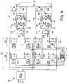
- Fig. 1illustrates a schematic diagram of a DC-to-DC converter according to the preferred embodiment of the present invention utilizing full-bridge soft switching pulse width modulated control.
- Fig. 2Aillustrates the current flow paths through the DC-to-DC converter of Fig. 1 during a first energy transfer stage (stage 1).
- Fig. 2Billustrates the current follow path through the DC-to-DC converter of Fig. 1 during a trailing leg transition stage (stage 2).
- Fig. 2Cillustrates the current flow path through the DC-to-DC converter of Fig. 1 during a free wheeling stage (stage 3).
- Fig. 2Dillustrates the current flow path through the DC-to-DC converter of Fig. 1 during a first part of the leading transition stage (stage 4).
- Fig. 2Eillustrates the current flow path through the DC-to-DC converter of Fig. 1 during a second part of the leading leg transition stage (stage 5).
- Fig. 2Fillustrates the current flow path through the DC-to-DC converter of Fig. 1 during a second energy transfer stage (stage 6).
- Fig. 3illustrates exemplary wave forms representative of the internal operation of the converter of Fig. 1.
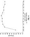
- Fig. 4illustrates a graph showing the efficiency of the converter of Fig. 1 at several load current levels.
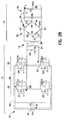
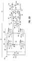
- Fig. 5illustrates an alternative embodiment of the present invention in which two converters have their primary sides connected in parallel to handle twice the input current and their secondary sides connected in series to produce twice the output voltage of a single converter.
- This parallel/series configurationcan be generalized to include n converter modules.
- a full-bridge converter 10which performs soft switching based on pulse width modulated (PWM) switching.
- the full-bridge converter 10includes a primary side 12 and a secondary side 14 interconnected through a transformer 13.
- the primary side 12includes a power source 16 and an input capacitor 18 connected in parallel with a leading leg 20 and a trailing leg 22.
- the leading leg 20includes first and second switching transistors Q1 and Q2, respectively, connected in series.
- the trailing leg 22includes third and fourth switching transistors Q3 and Q4, respectively, connected in series.
- a transformer 13includes primary and secondary windings 24 and 26, and a magnetizing inductance 48.
- a primary winding 24 of the transformer 13is connected at nodes 28 and 30 to the leading and trailing legs 20 and 22, respectively.
- the secondary winding 26 of the transformer 13is connected in parallel to a full-bridge rectifier 32, a free wheeling diode D9 and a low pass filter 34.
- the low pass filter 34includes an inductor 36 and a capacitor 38 connected in standard bridge configuration.
- the diode bridge 32includes four diodes D5-D8 connected in standard bridge configurations. The diode bridge 32 is connected at nodes 40 and 42 to the secondary side 26 of the transformer 13, and at nodes 44 and 46 to the free wheeling diode D9.
- the diode bridge 32includes saturable reactors SR1 and SR2 connected in series with diodes D5 and D6, respectively, in the first and second legs. As explained below, the saturable reactors SR1 and SR2 and the free wheeling diode D9 help support soft-PWM switching and allow the device to eliminate reverse recovery losses.
- the input of the converter 10is driven by the power source 16 which produces an input voltage Vin.
- Input capacitor 18smoothes the input voltage Vin and stores energy returned to the source 16 from the components of the primary side 12 during switching.
- Switching transistors Q1-Q4may be formed from metal oxide semiconductor field effect transistors (MOSFETS) and the like.
- MOSFETSmetal oxide semiconductor field effect transistors
- other types of switching elementsmay be utilized so long as the elements include, or are connected to circuits that emulate, parasitic capacitance and diode characteristics which may be utilized as explained below in connection with the preferred embodiment of the present invention.
- the switching transistors Q1-Q4are connected to form a full-bridge on the input side of the converter 10.
- Each of the switching transistors Q1-Q4inherently includes a parasitic diode and a parasitic capacitance.
- the parasitic diodes D1-D4 and parasitic capacitances C1-C4are illustrated as being connected in parallel across the drain and source of associated transistors Q1-Q4.
- the parasitic diodes D1-D4 and capacitances C1-C4are inherently associated with the switching transistors Q1-Q4.
- the transistors Q3, Q4are turned on and off by pulse width modulated (PWM) switching signals received at the gates G3-G4.
- PWMpulse width modulated
- the PWM switching signalsmay be modulated whereby each transistor Q3-Q4 is turned on upon receipt of a high pulse at the gate G3-G4 and remains on until the pulse goes low.
- Transistors Q1 and Q2are switched by approximately 50% duty cycle control signals running at the converter 10 operating frequency.
- the switching signalsare generated by a feed back control circuit 15 (explained in more detail below).
- the output of the secondary winding 26is rectified through the diode bridge 32 build from the diodes D5-D8.
- Two legs of the diode bridge 32contain saturable reactors SR1 and SR2 in series with the diodes D5 and D6, respectively.
- the saturable reactors SR1 and SR2operate in the same manner as a switch and reduce the diode reverse recovery losses (as explained in more detail below).
- the free wheeling diode D9connected in parallel across the output of the diode bridge 32, conducts in order to allow the output current to continue to flow to the load when the voltage drop across the transformer secondary winding 26 approaches zero.
- the output of the diode bridge rectifier 32passes through the low pass filter 34, which includes the inductor 36 and the capacitor 38 to provide the output voltage Vout.
- the feedback control circuit 15senses the output voltage Vout and adjusts the timing of the PWM switching signals applied to the gates G3-G4 of the transistors Q3-Q4 to turn transistors Q3-Q4 on and off.
- the feedback control circuit 15may use any conventional voltage sensing circuit to sample output voltage Vout, including an analog to digital converter (not shown).
- the feedback control circuit 15may also include a microcontroller which analyzes the digital representation of the output voltage Vout, determines what adjustments to make to the switch timing, and provides switching signals to the gate G1-G4 to control the transistors Q1-Q4.
- the entire feedback control circuit 15may be implemented with a single microcontroller, though discrete logic circuits may also be used to build the control circuit 15.
- Figs. 2A-2Ea step-by-step analysis is provided of the first half cycle of the converter 10 shown in Fig. 1.
- Fig 2Aillustrates the converter 10 while in an "energy transfer stage.”
- the converter 10initiates the energy transfer stage by soft switching transistors Q1 and Q3 to on states. The energy transfer stage continues until transistor Q3 is turned off.
- transistors Q1 and Q3are both on, the input power supply Vin transfers energy to the transformer primary winding 24 via the path illustrated by arrow 50.
- Currentflows through transistor Q1, primary winding 24, transistor Q3 and back to Vin.
- currentbuilds up in the inductance 48.
- the current buildup in inductance 48is later used to charge capacitor C3.
- Transistors Q1 and Q3remain on during the energy transfer stage.
- the current flow through saturable reactor SR1forces the saturable reactor SR1 into a low impedance saturation state after a very brief forward blocking state during which the saturable reactor SR1 transitions to the low impedance state.
- the saturable reactor SR1acts like a short circuit in that it presents substantially zero resistance to current flow.
- minimum poweris dissipated across the saturable reactor SR1 while current is flowing therethrough.
- the rectified voltage output of the diode rectifier 32keeps the free-wheeling diode D9 turned off.
- Fig. 3illustrates several waveforms within the converter 10 during different stages of the soft switching operation as controlled by the signals supplied to gates G1-G4.
- Vgs1 - Vgs4represent the voltage waveforms that appear across the gates G1-G4 to the source terminals of the transistors Q1-Q4, respectively.
- the feedback control circuit 15controls waveforms Vgs1 - Vgs4 through the PWM switching signals.
- Fig. 3also shows the current Img determined by input voltage 16 and the magnetizing inductance 48.
- the current through diodes D5 and D7is identical and shown as Id5 and Id7.
- the current through diodes D6 and D8is identical and shown as Id6 and Id8.
- Waveforms Vpr and Iprshow the voltage and current respectively across the primary winding 24.
- the time interval T1denotes the time during which the system remains in the energy transfer stage. During time interval T1, the voltage Vpr rises and the current Ipr builds in the transformer primary winding 24 as shown in Fig. 3.
- transistors Q1 and Q3are turned to an on state simultaneously since the switching signals Vgs1 and Vgs3 switch to a high state simultaneously. There is no delay between the times at which the transistors Q1 and Q3 are turned on. This simultaneous operation differs from the phase-shift soft switching converters known in the past in which the times differ at which transistors Q1 and Q3 are turned on by a delay determined by the phase difference.
- the time period during which the transistor Q3 remains onis based on PWM.
- the length of the energy transfer stageis determined by the width of the pulse (indicated in Fig. 3 by arrow 52) in the waveform Vgs3.
- the width of the pulse in waveform Vgs3is extended as the amount of energy increases which should be transferred to the load as determined by the control circuit 15. For example, if the output voltage Vout starts to sag, the control circuit 15 extends the width of waveform Vgs3 to transfer more energy to the load.
- the leading leg 12which comprises transistors Q1 and Q2 is operated at a duty cycle nominally of 50%, with a small dead time provided in which neither transistor Q1 nor transistor Q2 is turned on (as indicated in Fig. 3 by arrows 54 and 55).
- the trailing leg 14, which comprises transistors Q3 and Q4,is controlled with pulsed width modulated switching signals to provide control over the output voltage Vout.
- the times during which transistor Q3 is turned on (during the first half cycle) and transistor Q4 is turned on (during the second half cycle)are varied by adjusting the width of the switching pulses in the waveforms Vgs3 and Vgs4 in order to adjust the output voltage of the converter 10 to a predetermined level.
- the length of the first energy transfer stage(of the first half cycle) varies with the width of the pulse in waveform Vgs3.
- the control circuit 15determines when to turn off transistor Q3 by evaluating the feedback level of the output voltage Vout. Although transistor Q1 and transistor Q3 are turned on at the same time, transistor Q3 stays on for a variable amount of time.
- a trailing leg transition stageis described in connection with Figs. 2B and 3.
- the trailing leg transition stageis initiated when the control circuit 15 ends the energy transfer stage by turning off transistor Q3 while maintaining transistor Q1 in a conductive state.
- the time interval associated with the trailing leg transition stageis indicated in Fig. 3 at time interval T2.
- currentcontinues to flow in the direction shown by the arrows 50 and 56 in Fig. 2B due to the current previously built up in the magnetizing inductance 48 in the transformer 13 during the energy transfer stage (stage 1) (discussed above in connection with Fig. 2A).
- the current flow maintained by inductance 48charges capacitor C3 to nearly the input voltage Vin.
- the voltage at the transformer secondary winding 26also falls to approximately zero as the voltage across the transformer primary winding 24 approaches zero.
- Diode D5begins to turn off and enters a reverse recovery period as the voltage across the rectifier 32 is reduced.
- the load currentis diverted to the free wheeling diode D9, before D5 is turned off. That is, D5 is switched when zero current is flowing through it (zero-current switching).
- Saturable reactor SRlcomes out of saturation during the transition.
- the saturable reactor SR1operates with a large impedance when not in a saturation state. Thus, while in a non-saturated state, the impedance of the saturable reactor SR1 severely limits the magnitude of the diode reverse current and therefore reduces the associated power loss.
- the impedance of the saturable reactor SR1limits the voltage and current across the diode and thus reduces the amount of electromagnetic interference generated when the diode D5 is turned off and lowers the physical stress on the diode D5.
- the diodeslike the switching transistors, are soft switched. Because the voltage across the secondary winding 26 approaches zero, the secondary winding 26 appears as a short circuit between the cathodes of diodes D7 and D8 and the anodes of diodes D5 and D6. During this short circuit period, the saturable reactors SR1 and SR2 block current flow through the load and back through the secondary winding 26, thereby ensuring that the entire magnetizing energy is available for use by the primary side to do soft switching. Finally, when the transformer secondary winding 26 output voltage falls sufficiently, it causes the free-wheeling diode D9 to begin conducting a load current in order that current may flow along the path indicated by arrow 57.
- the free-wheeling stageis described in connection with Figs. 2C and 3.
- transistor Q1remains in an on state
- transistor Q3remains in an off state.
- the time interval T3identifies the free-wheeling stage.
- the free-wheeling stagebegins (and the trailing leg transition leg ends) when the voltage on capacitor C3 rises to the point where diode D4 turns on and clamps the voltage on capacitor C3 to the source voltage Vin plus one diode drop.
- the diode dropmay equal 0.7 volts, but will vary depending upon the type of diode used.
- the magnetizing inductance 48continues to maintain current in a circulating loop through transistor Q1, the primary winding 24, diode D4, and back to transistor Q1 as denoted by arrows 56 and 58.
- the circulating loopcontinues during a period known as the free-wheeling period. Since the magnetizing inductance 48 is typically large, only a small amount of current is needed to sustain the current circulation. The voltage across the transformer primary winding 24 is approximately zero. Even though diode D4 is conducting, the control circuit 15 does not turn on transistor Q4.
- the voltage across the transformer secondary winding 26also approaches zero.
- the inductor 36 of the filter 34continues to provide a current to the output load, thereby keeping Vout approximately constant.
- Saturable reactor SR1saturated earlier, remains reverse blocking, while saturable reactor SR2 is about to enter a forward blocking state during the free-wheeling period by transitioning from a high impedance state to a low impedance forward conducting state while diode D9 continues to free wheel.
- stage 4part one of a leading leg transition stage (stage 4) is described in connection with Figs. 2D and 3.
- the control circuit 15initiates part one of the leading leg transition stage by turning transistor Q1 off based on a predetermined converter operating frequency.
- the time interval T4represents the duration of part one of the leading leg transition stage.
- the magnetizing inductance 48maintains current flow in the direction indicated by arrows 60-66 in Fig. 2D. Current flow through capacitor C1 is in the direction of arrow 64 even though the transistor Q1 is turned off.
- the inductive current flow maintained by inductance 48decreases the voltage across capacitor C2 to approximately zero.
- part two of the leading leg transition stageis discussed in connection with Figs. 2E and 3. Rather than transitioning to a stage when transistors Q4 and Q2 are directly turned on, the control circuit 15 continues to hold transistors Q4 and Q2 off for a period of time.
- part two of the leading leg transition stageis indicated at time interval T5.
- the magnetizing inductance 48maintains the load current by forcing current flow through diodes D4 and D2.
- the control circuit 15initiates a transition to the second energy transfer stage. Recall that transistor Q4 was not turned on during the free-wheeling stage (time interval T3). The control circuit 15 waits to turn on transistor Q4 until the control circuit 15 is also ready to turn on transistor Q2 since current is already flowing through diode D4. Thus, no phase-shift is necessary (which would have been the case if transistor Q4 was turned on earlier than transistor Q2), and transistors Q2 and Q4 can be turned on simultaneously. As a result, the control circuit 15 can eliminate previously required phase-shift control signals and use PWM control over transistor Q4 (by adjusting the width of the waveform Vgs4 pulse) to adjust the output voltage while maintaining soft switching.
- the load currentcontinues to flow through the transformer secondary winding 26, the saturable reactor SR2, diode D6, the output filter 34, the load, diode D8 and back to the transformer secondary winding 26 (as illustrated by arrows 78 and 80).
- the converter 10continues through a second half cycle.
- the operation of the converter 10 during the second half cycleis symmetrical to the operation of the converter 10 during the first half cycle.
- transistor Q4is operated under PWM control in the same manner as transistor Q3 was in the first half cycle.
- An independent PWM control signal, shown as Vgs4 in Fig. 3controls transistor Q4, however.
- the first stage of the second half cycle, the energy transfer stage,is described in connection with Figs. 2F and 3.
- the second energy transfer stagebegins when transistors Q4 and Q2 are both simultaneously switched on by the control circuit 15. Referring to Fig. 3, the second energy transfer stage is indicated at time interval T6. Because both diode D4 and diode D2 were conducting prior to the beginning of the second energy transfer stage, transistors Q4 and Q2 are turned on with a voltage potential thereacross substantially corresponding to the diode voltage drop (e.g., 0.7 volts) across diodes D4 and D2. In other words, transistors Q4 and Q2 are soft switched, in a manner identical to the soft switching technique utilized above in connection with the first energy transfer stage for transistors Q1 and Q3.
- the input power supply Vintransfers energy to the transformer primary winding 24 in a direction reverse to the direction of energy transfer during the first energy transfer stage (described above in connection with Fig. 2A).
- the polarity of the voltage applied across the primary winding 24 during the second energy transfer stageis opposite to the polarity of the voltage applied across the primary winding 24 during the first energy transfer stage when transistors Q1 and Q3 were on.
- a voltagedevelops across the transformer secondary winding 26 that is a function of the turns ratio of the transformer 13.
- the voltage potential across the transformer secondary winding 26has a polarity that is opposed to the polarity of the voltage developed across secondary winding 26 during the first energy transfer stage (described above in connection with Fig. 2A).
- Current on the secondary side 14flows through saturable reactor SR2, diode D6, the output filter 34, the load, then back to diode D8 to the secondary winding 26 (as illustrated by arrows 88 and 90).
- Diodes D5 and D7are reverse biased and are fully in their reverse blocking state during the second energy transfer stage.
- the current flow through saturable reactor SR2forces the saturable reactor SR2 into a saturation stage, during which minimum power is dissipated across the saturable reactor SR2 as it acts as a virtual short circuit while current is flowing therethrough.
- the output of the diode bridge rectifier 32forces the free-wheeling diode D9 into an off state.
- the converter 10continues operating through the second half cycle in a manner symmetrical to that of the first half cycle.
- a detailed description of the second half cycleis therefore contained in the description of the first half cycle, except that symmetric circuit components should be substituted.
- the above-described operation of Q3applies now to the operation of Q4 and vice versa; the above-described operation of diodes D1 and D3 applies to the operation of diodes D2 and D4 and vice versa, etc.
- Fig. 4illustrates the measured efficiency of a converter 10 as described above.
- Fig. 4shows the best efficiency to be approximately 94%
- the efficiency of the converter 10varies a little with the load current.
- Fig. 4only reflects a set of measurements and does not depict a ceiling on the possible converter efficiency. Rather, the efficiency may continue to increase as further refinements are made to the converter.
- Fig. 5illustrates an alternative embodiment in which a multiple converter configuration is utilized including two converters 100 and 200 operating with their primary sides 112 and 212 in parallel and their secondary sides 114 and 214 in series. This concept can be generalized to multiple converter configurations using any number of converters 10.
- Fig. 5The configuration shown in Fig. 5 has a wide variety of applications.
- the demand for poweris increasing rapidly due to the ever-increasing functionality and complexity required in spacecraft electronic systems.
- Power supplies rated at a few kilowattsare frequently needed to provide power from a 28V DC bus. Delivering high power at 28V DC requires the power supply to handle large current.
- parallel connection of the primary side 12 of individual converters 10is an effective approach.
- converters 100 and 200individually operates as described above in connection with converter 10.
- similar elementshave been given similar reference numbers, but incremented by 100 or 200, respectively.
- leading and trailing legs 20 and 22 of Fig. 1have been renumbered as leading and trailing legs 120 and 122 in converter 100 and as leading and trailing legs 220 and 222 in converter 200.
- elements in converter 10 labelled with a letter followed by a single digit numbere.g., Q1, D4, C3
- gates G1-G4 of Fig. 1have been renumbered as gates G11-G14 in the converter 100 and as gates G21-G24 in the converter 200.
- the converters 100 and 200may be controlled by a common control circuit 115 through PWM switching signals connected to gates G11-G14 and G21-G24.
- the control circuit 115phase staggers or delays the PWM switching signals supplied to gates G21-G24 relative to the PWM switching signals supplied to gates G11-G14.
- the PWM switching signals of the upper converter 100may be phase staggered from the lower converter 200 by approximately 90 degrees in order that the dual configuration converter allows only one of converters 100 and 200 to draw input current at any instant in time. By staggering the control operations, the size, weight and cost of the input filters may be reduced since the filters need not handle as large amounts of ripple current caused when two converters operate simultaneously.
- the diodes D15-D18 and D25-D28 on the secondary sides 114 and 214 of the transformers 113 and 213need only handle half of the intended output voltage. This leads to a converter that may use faster, smaller, lighter and less expensive diodes.
Landscapes
- Engineering & Computer Science (AREA)
- Power Engineering (AREA)
- Dc-Dc Converters (AREA)
Abstract
Description
Claims (13)
- A pulse width modulated soft switching DC-to-DCconverter comprising:a DC input voltage source;a transformer with primary and secondary windings,said primary winding including a magnetizing inductancesuch that said primary winding operates as if an inductoris connected in parallel therewith;a switching circuit coupling said DC input voltage tosaid transformer primary winding, said switching circuitcomprising a first pair of switching devices connected inparallel with said DC input voltage and a second pair ofswitching devices connected in parallel with said DC inputvoltage and said first pair of switching devices, saidswitching devices selectively turning on and off toconvert said DC input voltage to an approximately squarewave voltage which is supplied to said primary winding ofsaid transformer;a rectifying circuit connected to said transformersecondary winding for rectifying an output voltage of saidtransformer secondary winding, said rectifying circuitcomprising first and second legs having first and secondsaturable reactors connected in series with first andsecond diodes, respectively, said first and secondsaturable reactors blocking current flow in thetransformer secondary winding when said first and second diodes are in reverse recovery states and when saidtransformer secondary winding is in a short circuit state;anda control circuit, connected to an output terminal ofsaid converter and connected to said switching devices,said control circuit generating pulse width modulated(PWM) switching signals turning said switching devices onand off, said control circuit turning on simultaneously afirst switching device in said first pair and a thirdswitching device in said second pair at a beginning of anenergy transfer stage, said energy transfer stagecorresponding to a time period during which said thirdswitching device remains on, said control circuitdetecting a voltage level at said output terminal andvarying a pulse width of a PWM switching signal thatcontrols said third switching device to vary a time periodduring which said third switching device remains on basedon said voltage level at said output terminal, saidcontrol circuit maintaining said first switching device inan on state after turning said third switching device toan off state for a sufficient period of time to achievesoft switching.
- A pulse width modulated soft switching DC-to-DCconverter according to claim 1, further comprising a freewheeling diode connected in parallel with output terminalsof said rectifying circuit.
- A pulse width modulated soft switching DC-to-DCconverter, according to claim 1, further comprising:a filter circuit connected in parallel with outputterminals of said rectifying circuit for performing lowpass filtering upon an output of said rectifying circuit.
- A pulse modulated soft switching DC-to-DCconverter, according to claim 1, wherein said controlcircuit includes a programmable microcontroller fordetecting said voltage level at said output terminal andfor controlling pulse widths of said PWM switching signalsto control soft switching operations of said first andsecond pairs of switching devices.
- A pulse width modulated soft switching DC-to-DCconverter, according to claim 1, when said control circuitends the energy transfer stage by turning off said thirdswitching device in said second pair, said control circuitinitiating a trailing leg transition stage when turningoff said third switching device.
- A pulse width modulated soft switching DC-to-DCconverter, according to claim 5, wherein said controlcircuit maintains said trailing leg transition stage froma time at which said third switching device is turned offuntil a time at which a capacitance of said thirdswitching device approximately equals said DC inputvoltage and a voltage potential across said primarywinding approximates a substantial minimum voltage.
- A pulse width modulated soft switching DC-to-DCconverter, according to claim 1, wherein said second pairof switching devices includes third and fourth switchingdevices, each of which contains corresponding third andfourth parasitic diodes, said fourth parasitic diodesbecoming forward biased and entering a conducted stageafter said control circuit turns off said third switchingdevice, thereby initiating a free-wheeling stage duringwhich current flows through a first switching device,through said primary winding, through said fourthparasitic diode and back through said first switchingdevice.
- A pulse width modulated soft switching DC-to-DCconverter, according to claim 1, wherein said first andsecond pairs of switching devices comprises first andsecond, and third and fourth switching devices,respectively, each of which includes a parasiticcapacitance and diode said control circuit initiating partone of a leading leg transition stage by turningtransistor Q1 off based on a predefined switchingfrequency during part one of said leading transitionstage, and inductance of said primary winding drivingcurrent flow through a parasitic diode of said forthswitching device, through said DC input voltage source,and through said parasitic diodes of said first and secondswitching devices in opposite directions, said current returning to said primary winding, said capacitance ofsaid first switching device supplementing current flowthrough said diode of said first switching device,inductive current flow driven by said inductance of saidprimary winding decrease a voltage potential across acapacitor of said second switch to approximately zero,thereby building a voltage potential across said primarywinding to equal substantially said DC input voltage, saidpart 1 of said leading leg transition stage ending when avoltage potential across said capacitance of said secondswitching device falls until said diode of said secondswitching device becomes conductive, thereby clamping saiddiode of said second switching device at a minimumpredetermined voltage.
- A pulse width modulated soft switching DC-to-DCconverter, according to claim 1, wherein said first andsecond switching devices include first and second, andthird and fourth switching devices, respectively, saidcontrol circuit maintaining said second and fourthswitching devices off throughout parts 1 and 2 of aleading leg transition stage corresponding to the timeperiod during which current reverses a direction of flowthrough said primary winding, said control circuit turningon said second and fourth transistors simultaneously toinitiate a second energy transfer stage following saidparts 1 and 2 of said leading leg transition stage.
- A pulse width modulated soft switching DC-to-DCconverter, according to claim 1, wherein said first pairof switching devices includes first and second switchingdevices and said second pair of switching devices includesthird and fourth switching devices, said control circuitsimultaneously turning on said first and third switchingdevices to initiate an energy transfer stage of a firstpath cycle, said control circuit simultaneously turning onsaid second and fourth switching devices during an energytransfer stage of a second path cycle, said controlcircuit ending said energy transfer stages of said firstand second half cycles by turning off said third andfourth switching devices, respectively, while maintainingon said first and second switching devices, respectively.
- A pulse with modulated soft switching DC-to-DCconverter, according to claim 1, further comprising acapacitor connected in parallel with said DC input voltagefor smoothing said input voltage.
- A pulse with modulated soft switching DC-to-DCconverter, according to claim 1, wherein said first pairof switching devices includes first and second switchingdevices connected in series via a first node, said secondpair of switching devices including third and fourthswitching devices connected in series via a second node,said primary winding of said transformer being connectedin series with said first and second nodes such that current flows in a first direction through said primarywinding when the first and third switching devices are onand such that current flows in a second opposite directionthrough said primary winding when said second and fourthswitching devices are turned on.
- A pulse with modulated soft switching DC-to-DCconverter, according to claim 1, wherein said rectifyingcircuit includes at least first and second saturablereactors connected in series with at least first andsecond diodes, said saturable reactors acting as shortcircuits while in saturated states while current flowtherethrough, said saturable reactors exhibiting highimpedance characteristics when in an unsaturated statewhile no or a minimum current flows therethrough, therebypreventing energy loss associated with diode reverserecovery.
Applications Claiming Priority (2)
| Application Number | Priority Date | Filing Date | Title |
|---|---|---|---|
| US858926 | 1997-05-19 | ||
| US08/858,926US5838558A (en) | 1997-05-19 | 1997-05-19 | Phase staggered full-bridge converter with soft-PWM switching |
Publications (3)
| Publication Number | Publication Date |
|---|---|
| EP0880220A2true EP0880220A2 (en) | 1998-11-25 |
| EP0880220A3 EP0880220A3 (en) | 1999-10-20 |
| EP0880220B1 EP0880220B1 (en) | 2006-06-21 |
Family
ID=25329518
Family Applications (1)
| Application Number | Title | Priority Date | Filing Date |
|---|---|---|---|
| EP98107215AExpired - LifetimeEP0880220B1 (en) | 1997-05-19 | 1998-04-21 | A phase staggered full-bridge converter with soft-PWM switching |
Country Status (6)
| Country | Link |
|---|---|
| US (1) | US5838558A (en) |
| EP (1) | EP0880220B1 (en) |
| JP (1) | JP3117677B2 (en) |
| KR (1) | KR100519440B1 (en) |
| DE (1) | DE69834981T2 (en) |
| TW (1) | TW406463B (en) |
Cited By (120)
| Publication number | Priority date | Publication date | Assignee | Title |
|---|---|---|---|---|
| WO2001033708A1 (en)* | 1999-11-05 | 2001-05-10 | Power-One, Inc. | Forward converter circuit having reduced switching losses |
| EP1681026A3 (en)* | 2005-01-13 | 2006-10-04 | Sherwood Services AG | Circuit and method for controlling an electrosurgical generator using a full bridge topology |
| EP1748539A3 (en)* | 2005-07-29 | 2010-11-17 | TDK Corporation | Switching power supply with surge voltage suppression |
| US8152802B2 (en) | 2009-01-12 | 2012-04-10 | Tyco Healthcare Group Lp | Energy delivery algorithm filter pre-loading |
| US8162932B2 (en) | 2009-01-12 | 2012-04-24 | Tyco Healthcare Group Lp | Energy delivery algorithm impedance trend adaptation |
| US8167875B2 (en) | 2009-01-12 | 2012-05-01 | Tyco Healthcare Group Lp | Energy delivery algorithm for medical devices |
| US8172836B2 (en) | 2008-08-11 | 2012-05-08 | Tyco Healthcare Group Lp | Electrosurgical system having a sensor for monitoring smoke or aerosols |
| US8174267B2 (en) | 2008-09-30 | 2012-05-08 | Vivant Medical, Inc. | Intermittent microwave energy delivery system |
| US8180433B2 (en) | 2008-09-30 | 2012-05-15 | Vivant Medical, Inc. | Microwave system calibration apparatus, system and method of use |
| US8211100B2 (en) | 2009-01-12 | 2012-07-03 | Tyco Healthcare Group Lp | Energy delivery algorithm for medical devices based on maintaining a fixed position on a tissue electrical conductivity v. temperature curve |
| US8231553B2 (en) | 2009-01-13 | 2012-07-31 | Tyco Healthcare Group Lp | Method for wireless control of electrosurgery |
| US8235917B2 (en) | 2009-01-13 | 2012-08-07 | Tyco Healthcare Group Lp | Wireless electrosurgical controller |
| US8242782B2 (en) | 2008-09-30 | 2012-08-14 | Vivant Medical, Inc. | Microwave ablation generator control system |
| US8248075B2 (en) | 2008-09-30 | 2012-08-21 | Vivant Medical, Inc. | System, apparatus and method for dissipating standing wave in a microwave delivery system |
| US8257349B2 (en) | 2008-03-28 | 2012-09-04 | Tyco Healthcare Group Lp | Electrosurgical apparatus with predictive RF source control |
| US8262652B2 (en) | 2009-01-12 | 2012-09-11 | Tyco Healthcare Group Lp | Imaginary impedance process monitoring and intelligent shut-off |
| US8287529B2 (en) | 2008-09-05 | 2012-10-16 | Tyco Healthcare Group Lp | Electrosurgical apparatus with high speed energy recovery |
| US8287527B2 (en) | 2008-09-30 | 2012-10-16 | Vivant Medical, Inc. | Microwave system calibration apparatus and method of use |
| US8298231B2 (en) | 2008-01-31 | 2012-10-30 | Tyco Healthcare Group Lp | Bipolar scissors for adenoid and tonsil removal |
| US8333759B2 (en) | 2009-01-12 | 2012-12-18 | Covidien Lp | Energy delivery algorithm for medical devices |
| US8346370B2 (en) | 2008-09-30 | 2013-01-01 | Vivant Medical, Inc. | Delivered energy generator for microwave ablation |
| US8377054B2 (en) | 2009-09-24 | 2013-02-19 | Covidien Lp | Automatic control circuit for use in an electrosurgical generator |
| US8377053B2 (en) | 2008-09-05 | 2013-02-19 | Covidien Lp | Electrosurgical apparatus with high speed energy recovery |
| US8382751B2 (en) | 2009-09-10 | 2013-02-26 | Covidien Lp | System and method for power supply noise reduction |
| US8403924B2 (en) | 2008-09-03 | 2013-03-26 | Vivant Medical, Inc. | Shielding for an isolation apparatus used in a microwave generator |
| US8409186B2 (en) | 2008-03-13 | 2013-04-02 | Covidien Lp | Crest factor enhancement in electrosurgical generators |
| US8454590B2 (en) | 2010-02-26 | 2013-06-04 | Covidien Lp | Enhanced lossless current sense circuit |
| US8610501B2 (en) | 2009-11-16 | 2013-12-17 | Covidien Lp | Class resonant-H electrosurgical generators |
| US8617154B2 (en) | 2010-06-25 | 2013-12-31 | Covidien Lp | Current-fed push-pull converter with passive voltage clamp |
| US8623007B2 (en) | 2010-06-30 | 2014-01-07 | Covidien Lp | Electrosurgical generator to ablation device adaptor |
| US8653994B2 (en) | 2012-03-21 | 2014-02-18 | Covidien Lp | System and method for detection of ADC errors |
| US8664934B2 (en) | 2012-01-27 | 2014-03-04 | Covidien Lp | System and method for verifying the operating frequency of digital control circuitry |
| US8668690B2 (en) | 2010-06-03 | 2014-03-11 | Covidien Lp | Apparatus and method for optimal tissue separation |
| US8685015B2 (en) | 2009-09-24 | 2014-04-01 | Covidien Lp | System and method for multi-pole phase-shifted radio frequency application |
| US8734444B2 (en) | 2008-10-10 | 2014-05-27 | Covidien Lp | System and method for delivering high current to electrosurgical device |
| US8790335B2 (en) | 2009-08-28 | 2014-07-29 | Covidien Lp | Electrosurgical generator |
| US8852179B2 (en) | 2008-10-10 | 2014-10-07 | Covidien Lp | Apparatus, system and method for monitoring tissue during an electrosurgical procedure |
| US8932291B2 (en) | 2012-04-13 | 2015-01-13 | Covidien Lp | Electrosurgical systems |
| US8944834B2 (en) | 2004-10-13 | 2015-02-03 | Covidien Ag | Universal foot switch contact port |
| US8968293B2 (en) | 2011-04-12 | 2015-03-03 | Covidien Lp | Systems and methods for calibrating power measurements in an electrosurgical generator |
| US8968290B2 (en) | 2012-03-14 | 2015-03-03 | Covidien Lp | Microwave ablation generator control system |
| US9028479B2 (en) | 2011-08-01 | 2015-05-12 | Covidien Lp | Electrosurgical apparatus with real-time RF tissue energy control |
| US9028481B2 (en) | 2011-01-05 | 2015-05-12 | Covidien Lp | System and method for measuring current of an electrosurgical generator |
| US9037447B2 (en) | 2012-01-27 | 2015-05-19 | Covidien Lp | Systems and methods for phase predictive impedance loss model calibration and compensation |
| US9050089B2 (en) | 2011-05-31 | 2015-06-09 | Covidien Lp | Electrosurgical apparatus with tissue site sensing and feedback control |
| US9099863B2 (en) | 2011-09-09 | 2015-08-04 | Covidien Lp | Surgical generator and related method for mitigating overcurrent conditions |
| US9119624B2 (en) | 2006-04-24 | 2015-09-01 | Covidien Ag | ARC based adaptive control system for an electrosurgical unit |
| US9192424B2 (en) | 2012-05-31 | 2015-11-24 | Covidien Lp | AC active load |
| US9192425B2 (en) | 2012-06-26 | 2015-11-24 | Covidien Lp | System and method for testing electrosurgical generators |
| US9198711B2 (en) | 2012-03-22 | 2015-12-01 | Covidien Lp | Electrosurgical system for communicating information embedded in an audio tone |
| US9270202B2 (en) | 2013-03-11 | 2016-02-23 | Covidien Lp | Constant power inverter with crest factor control |
| US9265560B2 (en) | 2011-02-25 | 2016-02-23 | Covidien Lp | System and method for detecting and suppressing arc formation during an electrosurgical procedure |
| US9271790B2 (en) | 2007-09-21 | 2016-03-01 | Coviden Lp | Real-time arc control in electrosurgical generators |
| GB2509009B (en)* | 2011-08-30 | 2016-03-09 | Ge Aviat Systems Ltd | Power distribution in aircraft |
| US9283028B2 (en) | 2013-03-15 | 2016-03-15 | Covidien Lp | Crest-factor control of phase-shifted inverter |
| WO2016045722A1 (en)* | 2014-09-24 | 2016-03-31 | Siemens Aktiengesellschaft | Electrical arrangement and method for generating a direct current |
| CN105637751A (en)* | 2013-10-09 | 2016-06-01 | 三菱电机株式会社 | In-vehicle charger |
| US9375250B2 (en) | 2012-04-09 | 2016-06-28 | Covidien Lp | Method for employing single fault safe redundant signals |
| US9375249B2 (en) | 2012-05-11 | 2016-06-28 | Covidien Lp | System and method for directing energy to tissue |
| US9375247B2 (en) | 2011-03-16 | 2016-06-28 | Covidien Lp | System and method for electrosurgical generator power measurement |
| US9456862B2 (en) | 2013-02-19 | 2016-10-04 | Covidien Lp | Electrosurgical generator and system |
| US9480523B2 (en) | 2012-01-27 | 2016-11-01 | Covidien Lp | Systems and methods for phase predictive impedance loss model calibration and compensation |
| US9498276B2 (en) | 2013-03-15 | 2016-11-22 | Covidien Lp | Systems and methods for narrowband real impedance control in electrosurgery |
| US9504516B2 (en) | 2013-05-31 | 2016-11-29 | Covidien LLP | Gain compensation for a full bridge inverter |
| US9519021B2 (en) | 2013-03-11 | 2016-12-13 | Covidien Lp | Systems and methods for detecting abnormalities within a circuit of an electrosurgical generator |
| US9522039B2 (en) | 2009-03-11 | 2016-12-20 | Covidien Lp | Crest factor enhancement in electrosurgical generators |
| US9522032B2 (en) | 2005-10-21 | 2016-12-20 | Covidien Ag | Circuit and method for reducing stored energy in an electrosurgical generator |
| US9529025B2 (en) | 2012-06-29 | 2016-12-27 | Covidien Lp | Systems and methods for measuring the frequency of signals generated by high frequency medical devices |
| US9539050B2 (en) | 2011-04-12 | 2017-01-10 | Covidien Lp | System and method for process monitoring and intelligent shut-off |
| US9559594B2 (en) | 2013-06-24 | 2017-01-31 | Covidien Lp | Dead-time optimization of resonant inverters |
| US9636165B2 (en) | 2013-07-29 | 2017-05-02 | Covidien Lp | Systems and methods for measuring tissue impedance through an electrosurgical cable |
| US9642670B2 (en) | 2013-10-29 | 2017-05-09 | Covidien Lp | Resonant inverter with a common mode choke |
| US9642665B2 (en) | 2006-01-24 | 2017-05-09 | Covidien Ag | Method and system for controlling an output of a radio-frequency medical generator having an impedance based control algorithm |
| US9700366B2 (en) | 2008-08-01 | 2017-07-11 | Covidien Lp | Polyphase electrosurgical system and method |
| US9768373B2 (en) | 2003-10-30 | 2017-09-19 | Covidien Ag | Switched resonant ultrasonic power amplifier system |
| US9770283B2 (en) | 2013-09-24 | 2017-09-26 | Covidien Lp | Systems and methods for improving efficiency of electrosurgical generators |
| US9782212B2 (en) | 2014-12-02 | 2017-10-10 | Covidien Lp | High level algorithms |
| US9839469B2 (en) | 2013-09-24 | 2017-12-12 | Covidien Lp | Systems and methods for improving efficiency of electrosurgical generators |
| US9861425B2 (en) | 2012-10-02 | 2018-01-09 | Covidien Lp | System and method for using resonance phasing for measuring impedance |
| US9867651B2 (en) | 2013-09-26 | 2018-01-16 | Covidien Lp | Systems and methods for estimating tissue parameters using surgical devices |
| US9872719B2 (en) | 2013-07-24 | 2018-01-23 | Covidien Lp | Systems and methods for generating electrosurgical energy using a multistage power converter |
| US9895186B2 (en) | 2013-03-11 | 2018-02-20 | Covidien | Systems and methods for detecting abnormalities within a circuit of an electrosurgical generator |
| US9901385B2 (en) | 2014-01-13 | 2018-02-27 | Covidien Lp | Systems and methods for multifrequency cable compensation |
| US9913679B2 (en) | 2013-10-16 | 2018-03-13 | Covidien Lp | Electrosurgical systems and methods for monitoring power dosage |
| US9921243B2 (en) | 2012-12-17 | 2018-03-20 | Covidien Lp | System and method for voltage and current sensing |
| US9949783B2 (en) | 2014-04-04 | 2018-04-24 | Covidien Lp | Systems and methods for optimizing emissions from simultaneous activation of electrosurgery generators |
| US9974595B2 (en) | 2014-04-04 | 2018-05-22 | Covidien Lp | Systems and methods for optimizing emissions from simultaneous activation of electrosurgery generators |
| US9987068B2 (en) | 2014-04-04 | 2018-06-05 | Covidien Lp | Systems and methods for optimizing emissions from simultaneous activation of electrosurgery generators |
| US10039588B2 (en) | 2009-12-16 | 2018-08-07 | Covidien Lp | System and method for tissue sealing |
| US10058374B2 (en) | 2013-09-26 | 2018-08-28 | Covidien Lp | Systems and methods for estimating tissue parameters using surgical devices |
| US10076383B2 (en) | 2012-01-25 | 2018-09-18 | Covidien Lp | Electrosurgical device having a multiplexer |
| US10105172B2 (en) | 2013-10-16 | 2018-10-23 | Covidien Lp | Radiofrequency amplifier impedance optimization |
| US10130412B2 (en) | 2013-09-26 | 2018-11-20 | Covidien Lp | Systems and methods for estimating tissue parameters using surgical devices |
| US10188446B2 (en) | 2013-10-16 | 2019-01-29 | Covidien Lp | Resonant inverter |
| US10188448B2 (en) | 2014-11-21 | 2019-01-29 | Covidien Lp | Electrosurgical system for multi-frequency interrogation of parasitic parameters of an electrosurgical instrument |
| US10278764B2 (en) | 2014-12-02 | 2019-05-07 | Covidien Lp | Electrosurgical generators and sensors |
| US10281496B2 (en) | 2014-12-02 | 2019-05-07 | Covidien Lp | Electrosurgical generators and sensors |
| US10285750B2 (en) | 2013-07-29 | 2019-05-14 | Covidien Lp | Systems and methods for operating an electrosurgical generator |
| US10292753B2 (en) | 2014-12-02 | 2019-05-21 | Covidien Lp | Electrosurgical generators and sensors |
| US10363086B2 (en) | 2014-10-31 | 2019-07-30 | Medtronic Advanced Energy Llc | Power monitoring circuitry and method for reducing leakage current in RF generators |
| US10376301B2 (en) | 2011-09-28 | 2019-08-13 | Covidien Lp | Logarithmic amplifier, electrosurgical generator including same, and method of controlling electrosurgical generator using same |
| US10376309B2 (en) | 2016-08-02 | 2019-08-13 | Covidien Lp | Ablation cable assemblies and a method of manufacturing the same |
| US10492850B2 (en) | 2014-04-04 | 2019-12-03 | Covidien Lp | Systems and methods for calculating tissue impedance in electrosurgery |
| US10610285B2 (en) | 2013-07-19 | 2020-04-07 | Covidien Lp | Electrosurgical generators |
| US10610287B2 (en) | 2016-05-05 | 2020-04-07 | Covidien Lp | Advanced simultaneous activation algorithm |
| US10617463B2 (en) | 2015-04-23 | 2020-04-14 | Covidien Lp | Systems and methods for controlling power in an electrosurgical generator |
| US10729484B2 (en) | 2013-07-16 | 2020-08-04 | Covidien Lp | Electrosurgical generator with continuously and arbitrarily variable crest factor |
| US10772673B2 (en) | 2016-05-02 | 2020-09-15 | Covidien Lp | Surgical energy system with universal connection features |
| US10842563B2 (en) | 2013-03-15 | 2020-11-24 | Covidien Lp | System and method for power control of electrosurgical resonant inverters |
| US10869712B2 (en) | 2016-05-02 | 2020-12-22 | Covidien Lp | System and method for high frequency leakage reduction through selective harmonic elimination in electrosurgical generators |
| US11006997B2 (en) | 2016-08-09 | 2021-05-18 | Covidien Lp | Ultrasonic and radiofrequency energy production and control from a single power converter |
| US11013548B2 (en) | 2005-03-31 | 2021-05-25 | Covidien Ag | Method and system for compensating for external impedance of energy carrying component when controlling electrosurgical generator |
| US11065053B2 (en) | 2016-08-02 | 2021-07-20 | Covidien Lp | Ablation cable assemblies and a method of manufacturing the same |
| US11090106B2 (en) | 2015-04-23 | 2021-08-17 | Covidien Lp | Control systems for electrosurgical generator |
| US11197715B2 (en) | 2016-08-02 | 2021-12-14 | Covidien Lp | Ablation cable assemblies and a method of manufacturing the same |
| US11272975B2 (en) | 2017-09-22 | 2022-03-15 | Covidien Lp | Systems and methods for controlled electrosurgical dissection |
| US11534226B2 (en) | 2017-09-22 | 2022-12-27 | Covidien Lp | Systems and methods for minimizing arcing of bipolar forceps |
| US11744631B2 (en) | 2017-09-22 | 2023-09-05 | Covidien Lp | Systems and methods for controlled electrosurgical coagulation |
| US12226143B2 (en) | 2020-06-22 | 2025-02-18 | Covidien Lp | Universal surgical footswitch toggling |
| US12333423B2 (en) | 2019-02-14 | 2025-06-17 | Covidien Lp | Systems and methods for estimating tissue parameters using surgical devices |
Families Citing this family (73)
| Publication number | Priority date | Publication date | Assignee | Title |
|---|---|---|---|---|
| KR100455651B1 (en)* | 1997-08-08 | 2005-01-17 | 삼성전자주식회사 | Multi-output dc/dc voltage converting apparatus and liquid crystal display, including multi-output dc/dc voltage converter for generating main power through choke system and auxiliary power through flyback system |
| JP3318240B2 (en)* | 1997-09-12 | 2002-08-26 | 松下電器産業株式会社 | Switching power supply |
| US20020104882A1 (en)* | 1998-04-09 | 2002-08-08 | Jeffrey F. Liu | Optical data card reader system |
| US7901400B2 (en) | 1998-10-23 | 2011-03-08 | Covidien Ag | Method and system for controlling output of RF medical generator |
| US20040167508A1 (en) | 2002-02-11 | 2004-08-26 | Robert Wham | Vessel sealing system |
| US7137980B2 (en) | 1998-10-23 | 2006-11-21 | Sherwood Services Ag | Method and system for controlling output of RF medical generator |
| US7364577B2 (en) | 2002-02-11 | 2008-04-29 | Sherwood Services Ag | Vessel sealing system |
| US6862195B2 (en)* | 1999-03-01 | 2005-03-01 | Delta Energy Systems (Switzerland) Ag | Soft transition converter |
| YU49125B (en)* | 1999-06-29 | 2004-03-12 | Milan Dr. Prokin | Bridge amplifier with voltage lifter |
| US6442047B1 (en) | 1999-10-08 | 2002-08-27 | Lambda Electronics, Inc. | Power conversion apparatus and methods with reduced current and voltage switching |
| US6407935B1 (en)* | 2000-05-30 | 2002-06-18 | Koninklijke Philips Electronics N.V. | High frequency electronic ballast with reactive power compensation |
| US6937483B2 (en)* | 2002-01-16 | 2005-08-30 | Ballard Power Systems Corporation | Device and method of commutation control for an isolated boost converter |
| ES2289307T3 (en) | 2002-05-06 | 2008-02-01 | Covidien Ag | BLOOD DETECTOR TO CONTROL AN ELECTROCHIRURGICAL UNIT. |
| US7255694B2 (en) | 2002-12-10 | 2007-08-14 | Sherwood Services Ag | Variable output crest factor electrosurgical generator |
| US7044948B2 (en) | 2002-12-10 | 2006-05-16 | Sherwood Services Ag | Circuit for controlling arc energy from an electrosurgical generator |
| US6954367B2 (en)* | 2002-12-29 | 2005-10-11 | System General Corp. | Soft-switching power converter |
| AU2004235739B2 (en) | 2003-05-01 | 2010-06-17 | Covidien Ag | Method and system for programming and controlling an electrosurgical generator system |
| JP3929428B2 (en)* | 2003-09-29 | 2007-06-13 | 三菱電機株式会社 | Power control device |
| WO2005050151A1 (en) | 2003-10-23 | 2005-06-02 | Sherwood Services Ag | Thermocouple measurement circuit |
| US7131860B2 (en) | 2003-11-20 | 2006-11-07 | Sherwood Services Ag | Connector systems for electrosurgical generator |
| US7300435B2 (en) | 2003-11-21 | 2007-11-27 | Sherwood Services Ag | Automatic control system for an electrosurgical generator |
| US7766905B2 (en) | 2004-02-12 | 2010-08-03 | Covidien Ag | Method and system for continuity testing of medical electrodes |
| US7780662B2 (en) | 2004-03-02 | 2010-08-24 | Covidien Ag | Vessel sealing system using capacitive RF dielectric heating |
| US7030587B2 (en)* | 2004-04-09 | 2006-04-18 | Visteon Global Technologies, Inc. | Configuration of converter switches and machine coils of a switched reluctance machine |
| JP4513456B2 (en)* | 2004-08-05 | 2010-07-28 | 富士電機ホールディングス株式会社 | DC-DC converter transformer magnetism detector |
| US20060279973A1 (en)* | 2005-06-13 | 2006-12-14 | Cheng-Chia Hsu | High efficiency DC to AC power converter |
| US7947039B2 (en) | 2005-12-12 | 2011-05-24 | Covidien Ag | Laparoscopic apparatus for performing electrosurgical procedures |
| US7513896B2 (en) | 2006-01-24 | 2009-04-07 | Covidien Ag | Dual synchro-resonant electrosurgical apparatus with bi-directional magnetic coupling |
| US9186200B2 (en) | 2006-01-24 | 2015-11-17 | Covidien Ag | System and method for tissue sealing |
| US7651493B2 (en) | 2006-03-03 | 2010-01-26 | Covidien Ag | System and method for controlling electrosurgical snares |
| US7648499B2 (en) | 2006-03-21 | 2010-01-19 | Covidien Ag | System and method for generating radio frequency energy |
| US7952892B2 (en)* | 2006-04-04 | 2011-05-31 | Power Integrations, Inc. | DC converters with constant and variable duty ratio switching |
| US8753334B2 (en) | 2006-05-10 | 2014-06-17 | Covidien Ag | System and method for reducing leakage current in an electrosurgical generator |
| US7460380B2 (en)* | 2006-06-26 | 2008-12-02 | System General Corp. | Highly efficient switching power converter using a charge pump to power the drive circuit |
| US7731717B2 (en) | 2006-08-08 | 2010-06-08 | Covidien Ag | System and method for controlling RF output during tissue sealing |
| US8034049B2 (en) | 2006-08-08 | 2011-10-11 | Covidien Ag | System and method for measuring initial tissue impedance |
| US7637907B2 (en) | 2006-09-19 | 2009-12-29 | Covidien Ag | System and method for return electrode monitoring |
| TWI326963B (en)* | 2006-12-14 | 2010-07-01 | Tungnan Inst Of Technology | Resonant converter and synchronous rectification driving circuit thereof |
| USD574323S1 (en) | 2007-02-12 | 2008-08-05 | Tyco Healthcare Group Lp | Generator |
| CN101287320A (en)* | 2007-04-13 | 2008-10-15 | 鸿富锦精密工业(深圳)有限公司 | Light source driver |
| US8152800B2 (en) | 2007-07-30 | 2012-04-10 | Vivant Medical, Inc. | Electrosurgical systems and printed circuit boards for use therewith |
| US20110299301A1 (en)* | 2008-12-19 | 2011-12-08 | Texas Instruments Incorporated | Fixed-frequency llc resonant power regulator |
| CN102047549B (en)* | 2009-01-07 | 2018-05-04 | 德克萨斯仪器股份有限公司 | Scan frequency LLC resonance power adjusters |
| US8932282B2 (en) | 2009-08-03 | 2015-01-13 | Covidien Lp | Power level transitioning in a surgical instrument |
| US20110199045A1 (en)* | 2010-02-15 | 2011-08-18 | Convenientpower Hk Ltd | Power transfer device and method |
| TWI394357B (en)* | 2009-12-17 | 2013-04-21 | Univ Nat Taipei Technology | Phase shift full bridge power conversion system and its control method |
| TWI406485B (en)* | 2010-02-26 | 2013-08-21 | Sheng Yu Tseng | An interleaving converter |
| JP5742110B2 (en)* | 2010-04-14 | 2015-07-01 | 日産自動車株式会社 | Power converter |
| JP5561210B2 (en)* | 2011-03-09 | 2014-07-30 | 株式会社豊田自動織機 | Non-contact power transmission device |
| US9306465B2 (en)* | 2011-06-10 | 2016-04-05 | Lear Corporation | Method for controlling a converter having variable frequency control and system for powering a vehicle load using same |
| US9397579B2 (en)* | 2011-07-15 | 2016-07-19 | O2Micro Inc | Full-bridge switching DC/DC converters and controllers thereof |
| US9033973B2 (en) | 2011-08-30 | 2015-05-19 | Covidien Lp | System and method for DC tissue impedance sensing |
| US9033970B2 (en) | 2011-09-20 | 2015-05-19 | Covidien Lp | Handheld medical devices including microwave amplifier unit at device handle |
| US9039692B2 (en) | 2011-09-20 | 2015-05-26 | Covidien Lp | Handheld medical devices including microwave amplifier unit at device handle |
| US9023025B2 (en) | 2011-09-20 | 2015-05-05 | Covidien Lp | Handheld medical devices including microwave amplifier unit at device handle |
| US9039693B2 (en) | 2011-09-20 | 2015-05-26 | Covidien Lp | Handheld medical devices including microwave amplifier unit at device handle |
| DE102011087283A1 (en)* | 2011-11-29 | 2013-05-29 | Siemens Ag | A clocking method of a series resonant DC / DC converter of a multipoint medium frequency feed-in converter of a traction converter |
| CN102710138A (en)* | 2012-05-28 | 2012-10-03 | 西安爱科赛博电气股份有限公司 | Harmonic direct current converter with wide range and low ZVS (zero-voltage-switching) output |
| US9048743B2 (en)* | 2012-08-08 | 2015-06-02 | Apple Inc. | Controlling an adapter transformer voltage |
| US20140153289A1 (en)* | 2012-11-30 | 2014-06-05 | Chung-Shan Institute Of Science And Technology | Secondary Side Serial Resonant Full-Bridge DC/DC Converter |
| KR101397728B1 (en)* | 2012-12-21 | 2014-05-20 | 한국과학기술원 | Power supplying apparatus |
| US9577539B2 (en)* | 2013-01-30 | 2017-02-21 | Tdk Corporation | Power supply device and power supply system that have a serial connection terminal, a reverse flow prevention rectifying device and a bypass rectifying device |
| US9461546B2 (en)* | 2013-02-08 | 2016-10-04 | Advanced Charging Technologies, LLC | Power device and method for delivering power to electronic devices |
| WO2014155604A1 (en)* | 2013-03-28 | 2014-10-02 | 三菱電機株式会社 | Dc-dc converter |
| CN104143919A (en)* | 2013-05-07 | 2014-11-12 | 台达电子工业股份有限公司 | Bidirectional DC Converter |
| CN103457477B (en)* | 2013-09-23 | 2015-09-30 | 武汉中原电子集团有限公司 | A kind of control method of phase-shifted soft switch converter |
| KR101751114B1 (en) | 2015-06-24 | 2017-06-27 | 삼성전기주식회사 | Synchronous rectifier and circuit for controlling the same |
| US10746806B2 (en) | 2016-03-22 | 2020-08-18 | Infineon Technologies Ag | Transistor bridge failure test |
| IL255948A (en)* | 2017-11-27 | 2018-01-31 | Abramovici Tal | Constant frequency dc/dc power converter |
| JP6823112B2 (en)* | 2019-06-10 | 2021-01-27 | 株式会社京三製作所 | Power converter |
| TWI748772B (en)* | 2020-11-30 | 2021-12-01 | 陞達科技股份有限公司 | Current determination circuit |
| TWI748868B (en)* | 2021-02-08 | 2021-12-01 | 大陸商蘇州明緯科技有限公司 | DC voltage conversion device |
| US20250096693A1 (en)* | 2023-09-19 | 2025-03-20 | Mps Korea Co., Ltd. | Dc-dc converter for battery charging circuit |
Family Cites Families (23)
| Publication number | Priority date | Publication date | Assignee | Title |
|---|---|---|---|---|
| JPS5194529A (en)* | 1975-02-15 | 1976-08-19 | ||
| US4039925A (en)* | 1976-06-10 | 1977-08-02 | Nasa | Phase substitution of spare converter for a failed one of parallel phase staggered converters |
| US4467388A (en)* | 1982-07-06 | 1984-08-21 | Hitachi Metals International Ltd. | Electromagnetic chuck power supply and controller |
| US4864479A (en)* | 1988-03-07 | 1989-09-05 | General Electric Company | Full-bridge lossless switching converter |
| US5198969A (en)* | 1990-07-13 | 1993-03-30 | Design Automation, Inc. | Soft-switching full-bridge dc/dc converting |
| SE9100595D0 (en)* | 1991-03-01 | 1991-03-01 | Carlstedt Elektronik Ab | ENERGY FREE POWER SUPPLY |
| US5132889A (en)* | 1991-05-15 | 1992-07-21 | Ibm Corporation | Resonant-transition DC-to-DC converter |
| US5235501A (en)* | 1991-07-19 | 1993-08-10 | The University Of Toledo | High efficiency voltage converter |
| US5245520A (en)* | 1991-10-10 | 1993-09-14 | Paul Imbertson | Asymmetrical duty cycle power converter |
| US5157592A (en)* | 1991-10-15 | 1992-10-20 | International Business Machines Corporation | DC-DC converter with adaptive zero-voltage switching |
| US5325283A (en)* | 1992-06-08 | 1994-06-28 | Center For Innovative Technology | Novel zero-voltage-switching family of isolated converters |
| US5442540A (en)* | 1992-06-12 | 1995-08-15 | The Center For Innovative Technology | Soft-switching PWM converters |
| US5373432A (en)* | 1992-12-10 | 1994-12-13 | Hughes Aircraft Company | Fixed frequency DC to DC converter with a variable inductance controller |
| EP0602835B1 (en)* | 1992-12-15 | 1996-05-01 | AT&T Corp. | Voltage control circuits |
| US5434768A (en)* | 1993-02-12 | 1995-07-18 | Rompower | Fixed frequency converter switching at zero voltage |
| US5372045A (en)* | 1993-02-12 | 1994-12-13 | Rosemount Inc. | Bridge pulse controlled constant current driver for magnetic flowmeter |
| US5568368A (en)* | 1993-05-03 | 1996-10-22 | General Electric Company | Square-wave converters with soft voltage transitions for ac power distribution systems |
| US5418703A (en)* | 1993-08-31 | 1995-05-23 | International Business Machines Corp. | DC-DC converter with reset control for enhanced zero-volt switching |
| US5539630A (en)* | 1993-11-15 | 1996-07-23 | California Institute Of Technology | Soft-switching converter DC-to-DC isolated with voltage bidirectional switches on the secondary side of an isolation transformer |
| US5438498A (en)* | 1993-12-21 | 1995-08-01 | Raytheon Company | Series resonant converter having a resonant snubber |
| US5563775A (en)* | 1994-06-16 | 1996-10-08 | Reliance Comm/Tech Corporation | Full bridge phase displaced resonant transition circuit for obtaining constant resonant transition current from 0° phase angle to 180° phase angle |
| US5500791A (en)* | 1994-10-21 | 1996-03-19 | General Electric Company | Power distribution system for generating regulated DC output voltages using a dual active bridge converter driven from an unregulated DC source |
| US5541827A (en)* | 1995-05-17 | 1996-07-30 | Doble Engineering Company | Reducing switching losses in a phase-modulated switch-mode amplifier |
- 1997
- 1997-05-19USUS08/858,926patent/US5838558A/ennot_activeExpired - Lifetime
- 1998
- 1998-04-13TWTW087105572Apatent/TW406463B/ennot_activeIP Right Cessation
- 1998-04-21EPEP98107215Apatent/EP0880220B1/ennot_activeExpired - Lifetime
- 1998-04-21DEDE69834981Tpatent/DE69834981T2/ennot_activeExpired - Lifetime
- 1998-04-30KRKR10-1998-0015601Apatent/KR100519440B1/ennot_activeExpired - Fee Related
- 1998-05-18JPJP10135357Apatent/JP3117677B2/ennot_activeExpired - Fee Related
Cited By (181)
| Publication number | Priority date | Publication date | Assignee | Title |
|---|---|---|---|---|
| WO2001033708A1 (en)* | 1999-11-05 | 2001-05-10 | Power-One, Inc. | Forward converter circuit having reduced switching losses |
| US6370051B1 (en) | 1999-11-05 | 2002-04-09 | Power-One, Inc. | Forward converter circuit having reduced switching losses |
| US9768373B2 (en) | 2003-10-30 | 2017-09-19 | Covidien Ag | Switched resonant ultrasonic power amplifier system |
| US8944834B2 (en) | 2004-10-13 | 2015-02-03 | Covidien Ag | Universal foot switch contact port |
| EP1681026A3 (en)* | 2005-01-13 | 2006-10-04 | Sherwood Services AG | Circuit and method for controlling an electrosurgical generator using a full bridge topology |
| US11013548B2 (en) | 2005-03-31 | 2021-05-25 | Covidien Ag | Method and system for compensating for external impedance of energy carrying component when controlling electrosurgical generator |
| EP1748539A3 (en)* | 2005-07-29 | 2010-11-17 | TDK Corporation | Switching power supply with surge voltage suppression |
| US9522032B2 (en) | 2005-10-21 | 2016-12-20 | Covidien Ag | Circuit and method for reducing stored energy in an electrosurgical generator |
| US10582964B2 (en) | 2006-01-24 | 2020-03-10 | Covidien Lp | Method and system for controlling an output of a radio-frequency medical generator having an impedance based control algorithm |
| US9642665B2 (en) | 2006-01-24 | 2017-05-09 | Covidien Ag | Method and system for controlling an output of a radio-frequency medical generator having an impedance based control algorithm |
| US9119624B2 (en) | 2006-04-24 | 2015-09-01 | Covidien Ag | ARC based adaptive control system for an electrosurgical unit |
| US9271790B2 (en) | 2007-09-21 | 2016-03-01 | Coviden Lp | Real-time arc control in electrosurgical generators |
| US8298231B2 (en) | 2008-01-31 | 2012-10-30 | Tyco Healthcare Group Lp | Bipolar scissors for adenoid and tonsil removal |
| US9522038B2 (en) | 2008-03-13 | 2016-12-20 | Covidien Lp | Crest factor enhancement in electrosurgical generators |
| US8409186B2 (en) | 2008-03-13 | 2013-04-02 | Covidien Lp | Crest factor enhancement in electrosurgical generators |
| US8257349B2 (en) | 2008-03-28 | 2012-09-04 | Tyco Healthcare Group Lp | Electrosurgical apparatus with predictive RF source control |
| US8608733B2 (en) | 2008-03-28 | 2013-12-17 | Covidien Lp | Electrosurgical apparatus with predictive RF source control |
| US9700366B2 (en) | 2008-08-01 | 2017-07-11 | Covidien Lp | Polyphase electrosurgical system and method |
| US8652128B2 (en) | 2008-08-11 | 2014-02-18 | Covidien Lp | Electrosurgical system having a sensor for monitoring smoke or aerosols |
| US8172836B2 (en) | 2008-08-11 | 2012-05-08 | Tyco Healthcare Group Lp | Electrosurgical system having a sensor for monitoring smoke or aerosols |
| US9254172B2 (en) | 2008-09-03 | 2016-02-09 | Covidien Lp | Shielding for an isolation apparatus used in a microwave generator |
| US8403924B2 (en) | 2008-09-03 | 2013-03-26 | Vivant Medical, Inc. | Shielding for an isolation apparatus used in a microwave generator |
| US8968295B2 (en) | 2008-09-05 | 2015-03-03 | Covidien Lp | Electrosurgical apparatus with high speed energy recovery |
| US8287529B2 (en) | 2008-09-05 | 2012-10-16 | Tyco Healthcare Group Lp | Electrosurgical apparatus with high speed energy recovery |
| US9186201B2 (en) | 2008-09-05 | 2015-11-17 | Covidien Lp | Electrosurgical apparatus with high speed energy recovery |
| US8377053B2 (en) | 2008-09-05 | 2013-02-19 | Covidien Lp | Electrosurgical apparatus with high speed energy recovery |
| US8180433B2 (en) | 2008-09-30 | 2012-05-15 | Vivant Medical, Inc. | Microwave system calibration apparatus, system and method of use |
| US9526576B2 (en) | 2008-09-30 | 2016-12-27 | Covidien Lp | Microwave ablation generator control system |
| US8248075B2 (en) | 2008-09-30 | 2012-08-21 | Vivant Medical, Inc. | System, apparatus and method for dissipating standing wave in a microwave delivery system |
| US8174267B2 (en) | 2008-09-30 | 2012-05-08 | Vivant Medical, Inc. | Intermittent microwave energy delivery system |
| US10070922B2 (en) | 2008-09-30 | 2018-09-11 | Covidien Lp | Microwave ablation generator control system |
| US8346370B2 (en) | 2008-09-30 | 2013-01-01 | Vivant Medical, Inc. | Delivered energy generator for microwave ablation |
| US10743935B2 (en) | 2008-09-30 | 2020-08-18 | Covidien Lp | Microwave ablation generator control system |
| US8287527B2 (en) | 2008-09-30 | 2012-10-16 | Vivant Medical, Inc. | Microwave system calibration apparatus and method of use |
| US8242782B2 (en) | 2008-09-30 | 2012-08-14 | Vivant Medical, Inc. | Microwave ablation generator control system |
| US9770287B2 (en) | 2008-10-10 | 2017-09-26 | Covidien Lp | System and method for delivering high current to electrosurgical device |
| US10278771B2 (en) | 2008-10-10 | 2019-05-07 | Covidien Lp | System and method for delivering 5 high current to electrosurgical device |
| US8734444B2 (en) | 2008-10-10 | 2014-05-27 | Covidien Lp | System and method for delivering high current to electrosurgical device |
| US8852179B2 (en) | 2008-10-10 | 2014-10-07 | Covidien Lp | Apparatus, system and method for monitoring tissue during an electrosurgical procedure |
| US8333759B2 (en) | 2009-01-12 | 2012-12-18 | Covidien Lp | Energy delivery algorithm for medical devices |
| US8262652B2 (en) | 2009-01-12 | 2012-09-11 | Tyco Healthcare Group Lp | Imaginary impedance process monitoring and intelligent shut-off |
| US8211100B2 (en) | 2009-01-12 | 2012-07-03 | Tyco Healthcare Group Lp | Energy delivery algorithm for medical devices based on maintaining a fixed position on a tissue electrical conductivity v. temperature curve |
| US8167875B2 (en) | 2009-01-12 | 2012-05-01 | Tyco Healthcare Group Lp | Energy delivery algorithm for medical devices |
| US8162932B2 (en) | 2009-01-12 | 2012-04-24 | Tyco Healthcare Group Lp | Energy delivery algorithm impedance trend adaptation |
| US8152802B2 (en) | 2009-01-12 | 2012-04-10 | Tyco Healthcare Group Lp | Energy delivery algorithm filter pre-loading |
| US8235917B2 (en) | 2009-01-13 | 2012-08-07 | Tyco Healthcare Group Lp | Wireless electrosurgical controller |
| US8231553B2 (en) | 2009-01-13 | 2012-07-31 | Tyco Healthcare Group Lp | Method for wireless control of electrosurgery |
| US9522039B2 (en) | 2009-03-11 | 2016-12-20 | Covidien Lp | Crest factor enhancement in electrosurgical generators |
| US9186202B2 (en) | 2009-08-28 | 2015-11-17 | Covidien Lp | Electrosurgical generator |
| US8790335B2 (en) | 2009-08-28 | 2014-07-29 | Covidien Lp | Electrosurgical generator |
| US9877771B2 (en) | 2009-09-10 | 2018-01-30 | Covidien Lp | System and method for power supply noise reduction |
| US8945115B2 (en) | 2009-09-10 | 2015-02-03 | Covidien Lp | System and method for power supply noise reduction |
| US8382751B2 (en) | 2009-09-10 | 2013-02-26 | Covidien Lp | System and method for power supply noise reduction |
| US8377054B2 (en) | 2009-09-24 | 2013-02-19 | Covidien Lp | Automatic control circuit for use in an electrosurgical generator |
| US8685015B2 (en) | 2009-09-24 | 2014-04-01 | Covidien Lp | System and method for multi-pole phase-shifted radio frequency application |
| US8779852B2 (en) | 2009-11-16 | 2014-07-15 | Covidien Lp | Class resonant-H electrosurgical generators |
| US8760226B2 (en) | 2009-11-16 | 2014-06-24 | Covidien Lp | Class resonant-H electrosurgical generators |
| US9705456B2 (en) | 2009-11-16 | 2017-07-11 | Covidien Lp | Class resonant-H electrosurgical generators |
| US8610501B2 (en) | 2009-11-16 | 2013-12-17 | Covidien Lp | Class resonant-H electrosurgical generators |
| US10039588B2 (en) | 2009-12-16 | 2018-08-07 | Covidien Lp | System and method for tissue sealing |
| US11154345B2 (en) | 2009-12-16 | 2021-10-26 | Covidien Lp | System and method for tissue sealing |
| US8454590B2 (en) | 2010-02-26 | 2013-06-04 | Covidien Lp | Enhanced lossless current sense circuit |
| US8668690B2 (en) | 2010-06-03 | 2014-03-11 | Covidien Lp | Apparatus and method for optimal tissue separation |
| US8617154B2 (en) | 2010-06-25 | 2013-12-31 | Covidien Lp | Current-fed push-pull converter with passive voltage clamp |
| US9522041B2 (en) | 2010-06-25 | 2016-12-20 | Covidien Lp | Current-fed push-pull converter with passive voltage clamp |
| US8623007B2 (en) | 2010-06-30 | 2014-01-07 | Covidien Lp | Electrosurgical generator to ablation device adaptor |
| US9028481B2 (en) | 2011-01-05 | 2015-05-12 | Covidien Lp | System and method for measuring current of an electrosurgical generator |
| US9987069B2 (en) | 2011-01-05 | 2018-06-05 | Covidien Lp | System and method for measuring current of an electrosurgical generator |
| US9265560B2 (en) | 2011-02-25 | 2016-02-23 | Covidien Lp | System and method for detecting and suppressing arc formation during an electrosurgical procedure |
| US10507054B2 (en) | 2011-02-25 | 2019-12-17 | Covidien Lp | System and method for detecting and supressing arc formation during an electrosurgical procedure |
| US9739814B2 (en) | 2011-03-16 | 2017-08-22 | Covidien Lp | System and method for electrosurgical generator power management |
| US9375247B2 (en) | 2011-03-16 | 2016-06-28 | Covidien Lp | System and method for electrosurgical generator power measurement |
| US8968293B2 (en) | 2011-04-12 | 2015-03-03 | Covidien Lp | Systems and methods for calibrating power measurements in an electrosurgical generator |
| US9539050B2 (en) | 2011-04-12 | 2017-01-10 | Covidien Lp | System and method for process monitoring and intelligent shut-off |
| US10543038B2 (en) | 2011-04-12 | 2020-01-28 | Covidien Lp | System and method for process monitoring and intelligent shut-off |
| US9918775B2 (en) | 2011-04-12 | 2018-03-20 | Covidien Lp | Systems and methods for calibrating power measurements in an electrosurgical generator |
| US9050089B2 (en) | 2011-05-31 | 2015-06-09 | Covidien Lp | Electrosurgical apparatus with tissue site sensing and feedback control |
| US10413347B2 (en) | 2011-08-01 | 2019-09-17 | Covidien Lp | Electrosurgical apparatus with real-time RF tissue energy control |
| US9028479B2 (en) | 2011-08-01 | 2015-05-12 | Covidien Lp | Electrosurgical apparatus with real-time RF tissue energy control |
| US10993761B2 (en) | 2011-08-01 | 2021-05-04 | Covidien Lp | Electrosurgical apparatus with real-time RF tissue energy control |
| US9908489B2 (en) | 2011-08-30 | 2018-03-06 | Ge Aviation Systems Limited | Power distribution in aircraft |
| GB2509009B (en)* | 2011-08-30 | 2016-03-09 | Ge Aviat Systems Ltd | Power distribution in aircraft |
| US9099863B2 (en) | 2011-09-09 | 2015-08-04 | Covidien Lp | Surgical generator and related method for mitigating overcurrent conditions |
| US9543750B2 (en) | 2011-09-09 | 2017-01-10 | Covidien Lp | Surgical generator and related method for mitigating overcurrent conditions |
| US10376301B2 (en) | 2011-09-28 | 2019-08-13 | Covidien Lp | Logarithmic amplifier, electrosurgical generator including same, and method of controlling electrosurgical generator using same |
| US11076906B2 (en) | 2011-09-28 | 2021-08-03 | Covidien Lp | Logarithmic amplifier, electrosurgical generator including same, and method of controlling electrosurgical generator using same |
| US10076383B2 (en) | 2012-01-25 | 2018-09-18 | Covidien Lp | Electrosurgical device having a multiplexer |
| US8664934B2 (en) | 2012-01-27 | 2014-03-04 | Covidien Lp | System and method for verifying the operating frequency of digital control circuitry |
| US9037447B2 (en) | 2012-01-27 | 2015-05-19 | Covidien Lp | Systems and methods for phase predictive impedance loss model calibration and compensation |
| US9116184B2 (en) | 2012-01-27 | 2015-08-25 | Covidien Lp | System and method for verifying the operating frequency of digital control circuitry |
| US9480523B2 (en) | 2012-01-27 | 2016-11-01 | Covidien Lp | Systems and methods for phase predictive impedance loss model calibration and compensation |
| US10022185B2 (en) | 2012-03-14 | 2018-07-17 | Covidien Lp | Microwave ablation generator control system |
| US8968290B2 (en) | 2012-03-14 | 2015-03-03 | Covidien Lp | Microwave ablation generator control system |
| US9375277B2 (en) | 2012-03-14 | 2016-06-28 | Covidien Lp | Microwave ablation generator control system |
| US8653994B2 (en) | 2012-03-21 | 2014-02-18 | Covidien Lp | System and method for detection of ADC errors |
| US9198711B2 (en) | 2012-03-22 | 2015-12-01 | Covidien Lp | Electrosurgical system for communicating information embedded in an audio tone |
| US9375250B2 (en) | 2012-04-09 | 2016-06-28 | Covidien Lp | Method for employing single fault safe redundant signals |
| US10799282B2 (en) | 2012-04-09 | 2020-10-13 | Covidien Lp | Method for employing single fault safe redundant signals |
| US10105174B2 (en) | 2012-04-09 | 2018-10-23 | Covidien Lp | Method for employing single fault safe redundant signals |
| US8932291B2 (en) | 2012-04-13 | 2015-01-13 | Covidien Lp | Electrosurgical systems |
| US9770284B2 (en) | 2012-05-11 | 2017-09-26 | Covidien Lp | System and method for directing energy to tissue |
| US9375249B2 (en) | 2012-05-11 | 2016-06-28 | Covidien Lp | System and method for directing energy to tissue |
| US9192424B2 (en) | 2012-05-31 | 2015-11-24 | Covidien Lp | AC active load |
| US9192425B2 (en) | 2012-06-26 | 2015-11-24 | Covidien Lp | System and method for testing electrosurgical generators |
| US9763726B2 (en) | 2012-06-26 | 2017-09-19 | Covidien Lp | System and method for testing electrosurgical generators |
| US10682173B2 (en) | 2012-06-26 | 2020-06-16 | Covidien Lp | System and method for testing electrosurgical generators |
| US10073125B2 (en) | 2012-06-29 | 2018-09-11 | Covidien Lp | Systems and methods for measuring the frequency of signals generated by high frequency medical devices |
| US9529025B2 (en) | 2012-06-29 | 2016-12-27 | Covidien Lp | Systems and methods for measuring the frequency of signals generated by high frequency medical devices |
| US10338115B2 (en) | 2012-06-29 | 2019-07-02 | Covidien Lp | Systems and methods for measuring the frequency of signals generated by high frequency medical devices |
| US9861425B2 (en) | 2012-10-02 | 2018-01-09 | Covidien Lp | System and method for using resonance phasing for measuring impedance |
| US9921243B2 (en) | 2012-12-17 | 2018-03-20 | Covidien Lp | System and method for voltage and current sensing |
| US10258407B2 (en) | 2013-02-19 | 2019-04-16 | Covidien Lp | Electrosurgical generator and system |
| US9456862B2 (en) | 2013-02-19 | 2016-10-04 | Covidien Lp | Electrosurgical generator and system |
| US9895186B2 (en) | 2013-03-11 | 2018-02-20 | Covidien | Systems and methods for detecting abnormalities within a circuit of an electrosurgical generator |
| US9270202B2 (en) | 2013-03-11 | 2016-02-23 | Covidien Lp | Constant power inverter with crest factor control |
| US9519021B2 (en) | 2013-03-11 | 2016-12-13 | Covidien Lp | Systems and methods for detecting abnormalities within a circuit of an electrosurgical generator |
| US9283028B2 (en) | 2013-03-15 | 2016-03-15 | Covidien Lp | Crest-factor control of phase-shifted inverter |
| US10842563B2 (en) | 2013-03-15 | 2020-11-24 | Covidien Lp | System and method for power control of electrosurgical resonant inverters |
| US9498276B2 (en) | 2013-03-15 | 2016-11-22 | Covidien Lp | Systems and methods for narrowband real impedance control in electrosurgery |
| US9504516B2 (en) | 2013-05-31 | 2016-11-29 | Covidien LLP | Gain compensation for a full bridge inverter |
| US11191584B2 (en) | 2013-06-24 | 2021-12-07 | Covidien Lp | Dead-time optimization of resonant inverters based on an input voltage of a tank |
| US9559594B2 (en) | 2013-06-24 | 2017-01-31 | Covidien Lp | Dead-time optimization of resonant inverters |
| US10729484B2 (en) | 2013-07-16 | 2020-08-04 | Covidien Lp | Electrosurgical generator with continuously and arbitrarily variable crest factor |
| US10610285B2 (en) | 2013-07-19 | 2020-04-07 | Covidien Lp | Electrosurgical generators |
| US9872719B2 (en) | 2013-07-24 | 2018-01-23 | Covidien Lp | Systems and methods for generating electrosurgical energy using a multistage power converter |
| US11135001B2 (en) | 2013-07-24 | 2021-10-05 | Covidien Lp | Systems and methods for generating electrosurgical energy using a multistage power converter |
| US9636165B2 (en) | 2013-07-29 | 2017-05-02 | Covidien Lp | Systems and methods for measuring tissue impedance through an electrosurgical cable |
| US10285750B2 (en) | 2013-07-29 | 2019-05-14 | Covidien Lp | Systems and methods for operating an electrosurgical generator |
| US9655670B2 (en) | 2013-07-29 | 2017-05-23 | Covidien Lp | Systems and methods for measuring tissue impedance through an electrosurgical cable |
| US9839469B2 (en) | 2013-09-24 | 2017-12-12 | Covidien Lp | Systems and methods for improving efficiency of electrosurgical generators |
| US9770283B2 (en) | 2013-09-24 | 2017-09-26 | Covidien Lp | Systems and methods for improving efficiency of electrosurgical generators |
| US11717339B2 (en) | 2013-09-26 | 2023-08-08 | Covidien Lp | Systems and methods for estimating tissue parameters using surgical devices |
| US10130412B2 (en) | 2013-09-26 | 2018-11-20 | Covidien Lp | Systems and methods for estimating tissue parameters using surgical devices |
| US10980595B2 (en) | 2013-09-26 | 2021-04-20 | Covidien Lp | Systems and methods for estimating tissue parameters using surgical devices |
| US10058374B2 (en) | 2013-09-26 | 2018-08-28 | Covidien Lp | Systems and methods for estimating tissue parameters using surgical devices |
| US9867651B2 (en) | 2013-09-26 | 2018-01-16 | Covidien Lp | Systems and methods for estimating tissue parameters using surgical devices |
| EP3057218A4 (en)* | 2013-10-09 | 2017-07-26 | Mitsubishi Electric Corporation | In-vehicle charger |
| CN105637751B (en)* | 2013-10-09 | 2018-10-09 | 三菱电机株式会社 | Onboard charger |
| US9812895B2 (en) | 2013-10-09 | 2017-11-07 | Mitsubishi Electric Corporation | In-vehicle charger |
| CN105637751A (en)* | 2013-10-09 | 2016-06-01 | 三菱电机株式会社 | In-vehicle charger |
| US10188446B2 (en) | 2013-10-16 | 2019-01-29 | Covidien Lp | Resonant inverter |
| US10105172B2 (en) | 2013-10-16 | 2018-10-23 | Covidien Lp | Radiofrequency amplifier impedance optimization |
| US9913679B2 (en) | 2013-10-16 | 2018-03-13 | Covidien Lp | Electrosurgical systems and methods for monitoring power dosage |
| US9642670B2 (en) | 2013-10-29 | 2017-05-09 | Covidien Lp | Resonant inverter with a common mode choke |
| US10898257B2 (en) | 2013-10-29 | 2021-01-26 | Covidien Lp | Resonant inverter with a common mode choke |
| US9901386B2 (en) | 2014-01-13 | 2018-02-27 | Covidien Lp | Systems and methods for multifrequency cable compensation |
| US9901385B2 (en) | 2014-01-13 | 2018-02-27 | Covidien Lp | Systems and methods for multifrequency cable compensation |
| US9974595B2 (en) | 2014-04-04 | 2018-05-22 | Covidien Lp | Systems and methods for optimizing emissions from simultaneous activation of electrosurgery generators |
| US11607264B2 (en) | 2014-04-04 | 2023-03-21 | Covidien Lp | Systems and methods for calculating tissue impedance in electrosurgery |
| US10492850B2 (en) | 2014-04-04 | 2019-12-03 | Covidien Lp | Systems and methods for calculating tissue impedance in electrosurgery |
| US9987068B2 (en) | 2014-04-04 | 2018-06-05 | Covidien Lp | Systems and methods for optimizing emissions from simultaneous activation of electrosurgery generators |
| US9949783B2 (en) | 2014-04-04 | 2018-04-24 | Covidien Lp | Systems and methods for optimizing emissions from simultaneous activation of electrosurgery generators |
| WO2016045722A1 (en)* | 2014-09-24 | 2016-03-31 | Siemens Aktiengesellschaft | Electrical arrangement and method for generating a direct current |
| US10363086B2 (en) | 2014-10-31 | 2019-07-30 | Medtronic Advanced Energy Llc | Power monitoring circuitry and method for reducing leakage current in RF generators |
| US10188448B2 (en) | 2014-11-21 | 2019-01-29 | Covidien Lp | Electrosurgical system for multi-frequency interrogation of parasitic parameters of an electrosurgical instrument |
| US10568680B2 (en) | 2014-11-21 | 2020-02-25 | Covidien Lp | Electrosurgical system for multi-frequency interrogation of parasitic parameters of an electrosurgical instrument |
| US10292753B2 (en) | 2014-12-02 | 2019-05-21 | Covidien Lp | Electrosurgical generators and sensors |
| US10987154B2 (en) | 2014-12-02 | 2021-04-27 | Covidien Lp | Electrosurgical generators and sensors |
| US10281496B2 (en) | 2014-12-02 | 2019-05-07 | Covidien Lp | Electrosurgical generators and sensors |
| US9782212B2 (en) | 2014-12-02 | 2017-10-10 | Covidien Lp | High level algorithms |
| US10278764B2 (en) | 2014-12-02 | 2019-05-07 | Covidien Lp | Electrosurgical generators and sensors |
| US11090106B2 (en) | 2015-04-23 | 2021-08-17 | Covidien Lp | Control systems for electrosurgical generator |
| US11129667B2 (en) | 2015-04-23 | 2021-09-28 | Covidien Lp | Systems and methods for controlling power in an electrosurgical generator |
| US11969201B2 (en) | 2015-04-23 | 2024-04-30 | Covidien Lp | Control systems for electrosurgical generator |
| US10617463B2 (en) | 2015-04-23 | 2020-04-14 | Covidien Lp | Systems and methods for controlling power in an electrosurgical generator |
| US10772673B2 (en) | 2016-05-02 | 2020-09-15 | Covidien Lp | Surgical energy system with universal connection features |
| US10869712B2 (en) | 2016-05-02 | 2020-12-22 | Covidien Lp | System and method for high frequency leakage reduction through selective harmonic elimination in electrosurgical generators |
| US11369429B2 (en) | 2016-05-05 | 2022-06-28 | Covidien Lp | Advanced simultaneous activation algorithm |
| US10610287B2 (en) | 2016-05-05 | 2020-04-07 | Covidien Lp | Advanced simultaneous activation algorithm |
| US11806067B2 (en) | 2016-05-05 | 2023-11-07 | Covidien Lp | Advanced simultaneous activation algorithm |
| US11065053B2 (en) | 2016-08-02 | 2021-07-20 | Covidien Lp | Ablation cable assemblies and a method of manufacturing the same |
| US11197715B2 (en) | 2016-08-02 | 2021-12-14 | Covidien Lp | Ablation cable assemblies and a method of manufacturing the same |
| US10376309B2 (en) | 2016-08-02 | 2019-08-13 | Covidien Lp | Ablation cable assemblies and a method of manufacturing the same |
| US11006997B2 (en) | 2016-08-09 | 2021-05-18 | Covidien Lp | Ultrasonic and radiofrequency energy production and control from a single power converter |
| US12426936B2 (en) | 2016-08-09 | 2025-09-30 | Covidien Lp | Ultrasonic and radiofrequency energy production and control from a single power converter |
| US11534226B2 (en) | 2017-09-22 | 2022-12-27 | Covidien Lp | Systems and methods for minimizing arcing of bipolar forceps |
| US11272975B2 (en) | 2017-09-22 | 2022-03-15 | Covidien Lp | Systems and methods for controlled electrosurgical dissection |
| US11744631B2 (en) | 2017-09-22 | 2023-09-05 | Covidien Lp | Systems and methods for controlled electrosurgical coagulation |
| US12262936B2 (en) | 2017-09-22 | 2025-04-01 | Covidien Lp | Systems and methods for controlled electrosurgical coagulation |
| US12333423B2 (en) | 2019-02-14 | 2025-06-17 | Covidien Lp | Systems and methods for estimating tissue parameters using surgical devices |
| US12226143B2 (en) | 2020-06-22 | 2025-02-18 | Covidien Lp | Universal surgical footswitch toggling |
Also Published As
| Publication number | Publication date |
|---|---|
| EP0880220B1 (en) | 2006-06-21 |
| TW406463B (en) | 2000-09-21 |
| EP0880220A3 (en) | 1999-10-20 |
| KR19980086689A (en) | 1998-12-05 |
| KR100519440B1 (en) | 2005-12-06 |
| JP3117677B2 (en) | 2000-12-18 |
| US5838558A (en) | 1998-11-17 |
| JPH10337021A (en) | 1998-12-18 |
| DE69834981T2 (en) | 2006-10-12 |
| DE69834981D1 (en) | 2006-08-03 |
Similar Documents
| Publication | Publication Date | Title |
|---|---|---|
| US5838558A (en) | Phase staggered full-bridge converter with soft-PWM switching | |
| US5132888A (en) | Interleaved bridge converter | |
| EP0508664B1 (en) | DC to DC converter | |
| US6765810B2 (en) | Full-wave coupled inductor power converter having synchronous rectifiers and two input switches that are simultaneously off for a time period of each switching cycle | |
| US5726869A (en) | Synchronous rectifier type DC-to-DC converter in which a saturable inductive device is connected in series with a secondary-side switching device | |
| US7272021B2 (en) | Power converter with isolated and regulated stages | |
| US5894412A (en) | System with open-loop DC-DC converter stage | |
| EP0428377B1 (en) | DC/DC switching converter circuit | |
| EP0602835B1 (en) | Voltage control circuits | |
| US5555494A (en) | Magnetically integrated full wave DC to DC converter | |
| US5959438A (en) | Soft-switched boost converter with isolated active snubber | |
| US5418703A (en) | DC-DC converter with reset control for enhanced zero-volt switching | |
| US6995987B2 (en) | DC—DC converters providing reduced deadtime | |
| US5307005A (en) | Zero current switching reverse recovery circuit | |
| EP0503862B1 (en) | Class E fixed frequency converter | |
| US6590791B1 (en) | High input voltage, high efficiency, fast transient voltage regulator module (VRM) | |
| US7272020B2 (en) | Isolated, current-fed, pulse width modulation, DC-DC converter | |
| US6185111B1 (en) | Switching power supply apparatus | |
| US20010036088A1 (en) | Efficient power conversion circuit having zero voltage switching | |
| US6744647B2 (en) | Parallel connected converters apparatus and methods using switching cycle with energy holding state | |
| US5870291A (en) | Asymmetrical half-bridge converter having adjustable parasitic resistances to offset output voltage DC bias | |
| US5877951A (en) | Circuit for and method of decreasing conducted and radiated electromagnetic interference of a power converter and a full bridge power converter employing the same | |
| US7050309B2 (en) | Power converter with output inductance | |
| US10348205B1 (en) | Coupled-inductor cascaded buck converter with fast transient response | |
| EP0534422B1 (en) | A power supply device |
Legal Events
| Date | Code | Title | Description |
|---|---|---|---|
| PUAI | Public reference made under article 153(3) epc to a published international application that has entered the european phase | Free format text:ORIGINAL CODE: 0009012 | |
| AK | Designated contracting states | Kind code of ref document:A2 Designated state(s):DE FR GB IT | |
| AX | Request for extension of the european patent | Free format text:AL;LT;LV;MK;RO;SI | |
| PUAL | Search report despatched | Free format text:ORIGINAL CODE: 0009013 | |
| AK | Designated contracting states | Kind code of ref document:A3 Designated state(s):AT BE CH CY DE DK ES FI FR GB GR IE IT LI LU MC NL PT SE | |
| AX | Request for extension of the european patent | Free format text:AL;LT;LV;MK;RO;SI | |
| 17P | Request for examination filed | Effective date:19991112 | |
| AKX | Designation fees paid | Free format text:DE FR GB IT | |
| 17Q | First examination report despatched | Effective date:20020919 | |
| RAP1 | Party data changed (applicant data changed or rights of an application transferred) | Owner name:NORTHROP GRUMMAN CORPORATION | |
| RAP1 | Party data changed (applicant data changed or rights of an application transferred) | Owner name:NORTHROP GRUMMAN CORPORATION | |
| GRAP | Despatch of communication of intention to grant a patent | Free format text:ORIGINAL CODE: EPIDOSNIGR1 | |
| GRAS | Grant fee paid | Free format text:ORIGINAL CODE: EPIDOSNIGR3 | |
| GRAA | (expected) grant | Free format text:ORIGINAL CODE: 0009210 | |
| AK | Designated contracting states | Kind code of ref document:B1 Designated state(s):DE FR GB IT | |
| PG25 | Lapsed in a contracting state [announced via postgrant information from national office to epo] | Ref country code:IT Free format text:LAPSE BECAUSE OF FAILURE TO SUBMIT A TRANSLATION OF THE DESCRIPTION OR TO PAY THE FEE WITHIN THE PRESCRIBED TIME-LIMIT;WARNING: LAPSES OF ITALIAN PATENTS WITH EFFECTIVE DATE BEFORE 2007 MAY HAVE OCCURRED AT ANY TIME BEFORE 2007. THE CORRECT EFFECTIVE DATE MAY BE DIFFERENT FROM THE ONE RECORDED. Effective date:20060621 | |
| REG | Reference to a national code | Ref country code:GB Ref legal event code:FG4D | |
| REF | Corresponds to: | Ref document number:69834981 Country of ref document:DE Date of ref document:20060803 Kind code of ref document:P | |
| ET | Fr: translation filed | ||
| PLBE | No opposition filed within time limit | Free format text:ORIGINAL CODE: 0009261 | |
| STAA | Information on the status of an ep patent application or granted ep patent | Free format text:STATUS: NO OPPOSITION FILED WITHIN TIME LIMIT | |
| 26N | No opposition filed | Effective date:20070322 | |
| GBPC | Gb: european patent ceased through non-payment of renewal fee | Effective date:20070421 | |
| PG25 | Lapsed in a contracting state [announced via postgrant information from national office to epo] | Ref country code:GB Free format text:LAPSE BECAUSE OF NON-PAYMENT OF DUE FEES Effective date:20070421 | |
| PG25 | Lapsed in a contracting state [announced via postgrant information from national office to epo] | Ref country code:FR Free format text:LAPSE BECAUSE OF NON-PAYMENT OF DUE FEES Effective date:20070430 | |
| PGFP | Annual fee paid to national office [announced via postgrant information from national office to epo] | Ref country code:IT Payment date:20080424 Year of fee payment:11 | |
| PGFP | Annual fee paid to national office [announced via postgrant information from national office to epo] | Ref country code:DE Payment date:20100423 Year of fee payment:13 | |
| PG25 | Lapsed in a contracting state [announced via postgrant information from national office to epo] | Ref country code:IT Free format text:LAPSE BECAUSE OF NON-PAYMENT OF DUE FEES Effective date:20090421 | |
| REG | Reference to a national code | Ref country code:DE Ref legal event code:R119 Ref document number:69834981 Country of ref document:DE | |
| REG | Reference to a national code | Ref country code:DE Ref legal event code:R119 Ref document number:69834981 Country of ref document:DE | |
| REG | Reference to a national code | Ref country code:DE Ref legal event code:R082 Ref document number:69834981 Country of ref document:DE Representative=s name:WUESTHOFF & WUESTHOFF PATENT- UND RECHTSANWAEL, DE | |
| REG | Reference to a national code | Ref country code:DE Ref legal event code:R082 Ref document number:69834981 Country of ref document:DE Representative=s name:WUESTHOFF & WUESTHOFF, PATENTANWAELTE PARTG MB, DE Effective date:20120814 Ref country code:DE Ref legal event code:R082 Ref document number:69834981 Country of ref document:DE Representative=s name:WUESTHOFF & WUESTHOFF PATENT- UND RECHTSANWAEL, DE Effective date:20120814 Ref country code:DE Ref legal event code:R081 Ref document number:69834981 Country of ref document:DE Owner name:NORTHROP GRUMMAN SYSTEMS CORPORATION, LOS ANGE, US Free format text:FORMER OWNER: NORTHROP GRUMMAN CORP., LOS ANGELES, CALIF., US Effective date:20120814 Ref country code:DE Ref legal event code:R081 Ref document number:69834981 Country of ref document:DE Owner name:NORTHROP GRUMMAN SYSTEMS CORPORATION, US Free format text:FORMER OWNER: NORTHROP GRUMMAN CORP., LOS ANGELES, US Effective date:20120814 | |
| PG25 | Lapsed in a contracting state [announced via postgrant information from national office to epo] | Ref country code:DE Free format text:LAPSE BECAUSE OF NON-PAYMENT OF DUE FEES Effective date:20111031 |