EP0879547B1 - Model-based predictive control of thermal processing - Google Patents
Model-based predictive control of thermal processingDownload PDFInfo
- Publication number
- EP0879547B1 EP0879547B1EP97904022AEP97904022AEP0879547B1EP 0879547 B1EP0879547 B1EP 0879547B1EP 97904022 AEP97904022 AEP 97904022AEP 97904022 AEP97904022 AEP 97904022AEP 0879547 B1EP0879547 B1EP 0879547B1
- Authority
- EP
- European Patent Office
- Prior art keywords
- temperature
- output
- model
- future
- reactor
- Prior art date
- Legal status (The legal status is an assumption and is not a legal conclusion. Google has not performed a legal analysis and makes no representation as to the accuracy of the status listed.)
- Expired - Lifetime
Links
Images


Classifications
- H—ELECTRICITY
- H05—ELECTRIC TECHNIQUES NOT OTHERWISE PROVIDED FOR
- H05B—ELECTRIC HEATING; ELECTRIC LIGHT SOURCES NOT OTHERWISE PROVIDED FOR; CIRCUIT ARRANGEMENTS FOR ELECTRIC LIGHT SOURCES, IN GENERAL
- H05B1/00—Details of electric heating devices
- H05B1/02—Automatic switching arrangements specially adapted to apparatus ; Control of heating devices
- G—PHYSICS
- G05—CONTROLLING; REGULATING
- G05B—CONTROL OR REGULATING SYSTEMS IN GENERAL; FUNCTIONAL ELEMENTS OF SUCH SYSTEMS; MONITORING OR TESTING ARRANGEMENTS FOR SUCH SYSTEMS OR ELEMENTS
- G05B13/00—Adaptive control systems, i.e. systems automatically adjusting themselves to have a performance which is optimum according to some preassigned criterion
- G05B13/02—Adaptive control systems, i.e. systems automatically adjusting themselves to have a performance which is optimum according to some preassigned criterion electric
- G05B13/04—Adaptive control systems, i.e. systems automatically adjusting themselves to have a performance which is optimum according to some preassigned criterion electric involving the use of models or simulators
- G05B13/048—Adaptive control systems, i.e. systems automatically adjusting themselves to have a performance which is optimum according to some preassigned criterion electric involving the use of models or simulators using a predictor
- G—PHYSICS
- G05—CONTROLLING; REGULATING
- G05B—CONTROL OR REGULATING SYSTEMS IN GENERAL; FUNCTIONAL ELEMENTS OF SUCH SYSTEMS; MONITORING OR TESTING ARRANGEMENTS FOR SUCH SYSTEMS OR ELEMENTS
- G05B13/00—Adaptive control systems, i.e. systems automatically adjusting themselves to have a performance which is optimum according to some preassigned criterion
- G05B13/02—Adaptive control systems, i.e. systems automatically adjusting themselves to have a performance which is optimum according to some preassigned criterion electric
- G05B13/0265—Adaptive control systems, i.e. systems automatically adjusting themselves to have a performance which is optimum according to some preassigned criterion electric the criterion being a learning criterion
- G05B13/027—Adaptive control systems, i.e. systems automatically adjusting themselves to have a performance which is optimum according to some preassigned criterion electric the criterion being a learning criterion using neural networks only
- G—PHYSICS
- G05—CONTROLLING; REGULATING
- G05D—SYSTEMS FOR CONTROLLING OR REGULATING NON-ELECTRIC VARIABLES
- G05D23/00—Control of temperature
- G05D23/19—Control of temperature characterised by the use of electric means
- G05D23/1917—Control of temperature characterised by the use of electric means using digital means
- G—PHYSICS
- G05—CONTROLLING; REGULATING
- G05D—SYSTEMS FOR CONTROLLING OR REGULATING NON-ELECTRIC VARIABLES
- G05D23/00—Control of temperature
- G05D23/19—Control of temperature characterised by the use of electric means
- G05D23/1927—Control of temperature characterised by the use of electric means using a plurality of sensors
- G05D23/193—Control of temperature characterised by the use of electric means using a plurality of sensors sensing the temperaure in different places in thermal relationship with one or more spaces
- G05D23/1931—Control of temperature characterised by the use of electric means using a plurality of sensors sensing the temperaure in different places in thermal relationship with one or more spaces to control the temperature of one space
Definitions
- the inventionrelates to automatic feedback control of thermal processing.
- the inventionpertains to model-based predictive temperature control of thermal process reactors such as used in semiconductor processing.
- polycrystalline silicontypically takes place at 600-700°C where as a rule of thumb a 2% uniformity degradation is incurred for every degree of temperature gradient.
- polysilicon depositionmultiple reflections and optical interference within the deposited overlayers can give rise to emissive or absorptive changes with overlayer thickness, exacerbating the problem of maintaining temperature uniformity (J.C. Liao, T.I. Kamins, "Power Absorption During Polysilicon Deposition in a Lamp-Heated CVD Reactor, J. Appld. Phys., 67(8), 3848-3852 (1990)).
- patterned layerscan also lead to variations in light absorption across the wafer, creating local temperature gradients.
- the aforementioned factors complicating the control system designare not only manifest for rapid thermal chemical vapor deposition (RTCVD) systems, but apply to thermal processing (TP) systems in general, where the need for precise process control is balanced by the demand for minimal process cycle times.
- RTCVDrapid thermal chemical vapor deposition
- TPthermal processing
- the generally short process cycle times and fast dynamics of the single-wafer systemsrender dynamic control of temperature uniformity a necessity of considerable technical difficulty.
- the radiant heating systems used for rapid wafer heatingcomprise either arc lamps or banks of linear tungsten-halogen lamps divided into several independently-controllable heating zones.
- the wafer itselfin principle, represents a complex thermal system whose interaction with the radiant energy is inherently nonlinear.
- the first componentmodels the (two-dimensional) heat balance of the wafer and is used to compute the steady-state wafer temperature profile for a given heat flux from the lamps.
- the second componentmodels the heat flux from the lamps as a function of the individual lamp powers.
- a least-squares methodis used to fit a quadratic relationship between the desired temperature at discrete radial positions on the wafer and the flux density due to the lamps.
- the lamp modelis used to determine optimal relative power settings for the lamps that approximate the required flux. This method only applies to the uniformity control in steady-state, i.e., constant input.
- Norman, et al. (1991)consider not only the steady-state optimization problem, but also the problem of designing an optimal trajectory.
- the dynamic modelis a finite-difference approximation to the one-dimensional heat equation, including the effects of conduction in the wafer, convective heat loss from the wafer, and radiative transfer.
- a minimax solutionis chosen for the steady-state uniformity optimization and trajectory following.
- Dynamic system modelingis an essential ingredient of predictive control laws, which provide the fundamental structure for a unique class of contemporary control algorithms.
- system or plant control strategiesare based on predicted future plant behavior predicated on a suitably accurate dynamic plant model.
- the future control strategiesare not static and do not extend arbitrarily to future time slots; but rather are periodically updated in accordance with the plant model in a so-called receding horizon fashion.
- predictive controlhas been the subject of extensive research and development. Indeed, predictive control is the central theme behind the benchmark works of Cutler and Ramaker in their Dynamic Matrix Control (DMC) algorithm (C. Cutler, B.L.
- DMCDynamic Matrix Control
- Ramaker"Dynamic Matrix Control ⁇ A Computer Control Algorithm," Joint Automatic Controls Conference Proceedings , San Francisco, 1980) and Richalet, et al., in their Model Algorithmic Control (MAC) algorithm
- MACModel Algorithmic Control
- J.A. Richalet, A. Rault, J.D. Testud, J. Papon"Model Predictive Heuristic Control: Application to Industrial Processes,” Automatica , Vol. 14, No. 413, 1978.
- Further predictive and adaptive characteristicsare incorporated by R.M.C. de Keyser, et al., “Self-Tuning Predictive Control," Journal A , Vol. 22, No. 4, pp.
- DMCIn DMC and other similar approaches, plant models are identified and cast in the form of deterministic impulse-response or step-response models. While these model forms are well-understood, they are often computationally cumbersome and present significant compromises between accuracy and response for long-range model predictions. Further, DMC appears to be incapable of handling non-minimum phase and open-loop unstable plants. A significant redeeming feature of DMC is that of the receding horizon, after which control increments are assumed to be zero. This advantageous assumption is incorporated in GPC, which in various derivations also utilizes extensions of Auto-Regressive Moving Average (ARMA) plant models such as CARMA or CARIMA (Controlled Auto-Regressive Moving Average, CAR-integrated-MA).
- ARMAAuto-Regressive Moving Average
- the ARMA plant modelsare generally represented by expressions involving polynomials A, B and C of the time-shift operator q -1 .
- Such modelsrepresent both the plant dynamics via the polynomials A,B and the disturbance via A,C.
- a particular advantageis that the number of parameters in the model is minimal so that they can be estimated with high efficiency.
- Clarke, et al.the long-range plant predictions are best accomplished by recursion of an associated Diophantine equation involving the model parameters.
- a similar ARMA model and recursive model predictionis also found in US Patent No. 5,301,101 by MacArthur, et al., which discloses an adaptive receding horizon-based controller incorporating means for operating cost minimization.
- A. Karaduman et al(“Nonlinear model predictive temperature control of a batch polymerization reactor", Advances in Process Control, 27 September 1995, pp 203-210, XP002081211 UK) describe an alternative temperature reactor, in the form of a tank reactor for wet chemical polymerization.
- a batch stirred tank reactorhas a cooling jacket, a manually controlled elecric heater, and equipment for online computer control. The reactor temperature is controlled by manipulating the flow rate of cooling water into the jacket during a heating generating phase of the reaction.
- Predictive controlhas applications in other fields.
- US-A-5 301 101describes a heating and air conditioning system for maintaining the temperature of a building, which uses a linear process model to achieve the predictive control.
- a first aspect of the present inventionis directed to a temperature controlled thermal process reactor comprising:
- a second aspect of the present inventionis directed to a method of controlling a thermal process in a reactor, the reactor comprising a reaction chamber enclosing an object to be heated, a plurality of sources of thermal energy which heat said object, a plurality of thermal sensors, each sensor configured to measure a sensor temperature related to an actual temperature of said object, where each thermal sensor provides an output signal representative of said sensor temperature, and where each of said sources of thermal energy affects each of said sensor temperatures, and a model-based predictive temperature controller comprising a nonlinear process model, the method comprising the steps of:
- the model-based predictive control system of the present inventionis herein illustrated in the context of rapid thermal processing (RTP) systems, and in particular a rapid thermal chemical vapor deposition (RTCVD) system, which itself makes advantageous use of the superior degree of temperature uniformity provided by the present invention.
- RTPrapid thermal processing
- RTCVDrapid thermal chemical vapor deposition
- the apparatusis shown in generally schematic fashion, and only those portions necessary to illustrate the inventive concepts disclosed herein have been included.
- the apparatusis intended to be enclosed within and supported by a surrounding enclosure (not shown) in and on which necessary gaseous reactant flow controls, process controls, instrumentation, and other attendant mechanisms are intended to be housed and mounted.
- the RTCVD system 30 illustrated in Figure 1comprises a reaction chamber 30 of the horizontal flow type formed of a material transparent to radiant heat energy, such as fused quartz.
- the reaction chamber 30may comprises a tubular shaft having a cross-section defining a reactant gas flow passage 28.
- the substrate or wafer 22may be supported in the center of reaction chamber 30 by a circular, slab-like susceptor 24 held in place by a rotatable driveshaft assembly 26 extending out of the reaction chamber 30.
- the susceptor 24is generally fabricated from a material which is opaque to the radiant heat energy supplied from the radiant heat source, and is preferably thermally conductive.
- the susceptor 24may be fabricated from a material such as graphite.
- thermocouples 44, 46, 48, 50are imbedded in the susceptor 24 for determining the local substrate temperature at predetermined positions on the substrate 22, shown here at respective wafer locations center 44, front 46, side 48, and rear 50.
- the thermocouple signalsare supplied to the temperature controller discussed below.
- the radiant heating systems used for rapid wafer heatingin general comprise either arc lamps or banks of elongated tungsten-halogen lamps divided into several independently-controllable heating zones.
- the radiant heat source shown in Figure 1comprises two banks of high-power elongated tungsten-halogen lamps located above and below the reaction chamber 30.
- the upper bank of lampsis oriented parallel to the process gas flow 28 and the plurality of upper bank lamps are divided into portions comprising a center zone 34 and two side zones 40, corresponding to their relative proximity with respect to the wafer 22 and gas flow 28.
- the lower bank of lampsis oriented orthogonal to the process gas flow 28, and the plurality of lower bank lamps are divided into portions comprising a center zone 32, a front zone 38 and a rear zone 36, corresponding to their relative proximity with respect to the wafer 22 and gas flow 28.
- the electrical power supplied to the lamps by lamp driversis typically controlled by a plurality of SCR power packs (discussed below) configured to control the duty cycle or phase angle over which the electrical power is supplied to combinations of lamps affecting specific heating zones.
- the SCR firing phase angleis preferably adjusted to render a linearized power input to the lamps as done, for example, in so-called V 2 or V*I modes of operation.
- the substrate 22is placed into the reaction chamber 30 and onto the susceptor 24 at the beginning of a process cycle.
- a reactant gasflows through the reaction chamber 30 in the direction indicated by the gas flow arrow 28 to deposit materials on the substrate 22.
- a desired sequence of thermal process stepsproceeds in concert with the reactive gas processing.
- the thermal processing sequenceis performed by adjusting the power level of the lamps to achieve a desired wafer temperature at a specific time in the process cycle.
- the radiant heat energy supplied to various heating zonesis controlled on the basis of temperature measurements within the respective heating zones, which information is supplied to the temperature control system discussed below.
- the substrate 22is removed from the reaction chamber 30 upon completion of the process cycle.
- the cold-wall and warm-wall reaction chamberssuch as that shown in Figure 1 are inherently non-isothermal.
- achieving a uniform temperature distributionis complicated by non-uniform heat flow, wafer geometry and attendant optical properties.
- the position, orientation and power level of lamps shown in Figure 1are in principle configured to provide a uniform temperature distribution over the wafer 22 by supplying an appropriate spatial and temporal distribution of heat energy.
- the plurality of lampscomprising different zones, for example, the side zones 40, as well as those of front and back zones 38 and 36, are supplied with varying electrical power levels comprising the multivariable control inputs. These control inputs produce varying radiant power levels in different heating zones to affect the temperature distribution over the substrate 22 during wafer processing.
- the various lamp operating powersare adjusted by a temperature controller operating on the basis of real-time temperature feedback provided by thermocouples 44, 46, 48 and 50 comprising the multivariable control output.
- the action of the temperature control systempreferably compensates the aforementioned non-uniform thermal characteristics of the wafer 22 and the reactor 20 to affect a uniform wafer temperature distribution.
- an exemplary prior art multivariable temperature control system for an RTCVD reactormay comprise a plurality of Proportional-Integral-Differential (PID) controllers well-known in the art, and configured in a so-called master-slave arrangement.
- a top view of the wafer 22shows the relative positions of the lamp heating zones 32, 34, 36, 38, 40 and 42 and the sensing thermocouples 44, 46, 48 and 50 with respect to the wafer 22 and the gas flow vector 28, as previously described.
- the temperature sensors 44, 46,48 and 50are connected to supply respective PID controllers 64, 66, 68, and 70 with signals indicative of the local wafer 22 temperature.
- the PID controllers 64, 66, 68 and 70are also connected to sources of reference signals, which supply each PID controller with a respective temperature reference signal or set-point.
- a process controller 62is connected to supply the center PID controller 64 with the global or master set-point information, while the PID controllers 66, 68 and 70 are connected and referenced to the center temperature sensor 44 of the wafer 22.
- the output signals of the PID controllers 64, 66, 68 and 70are in turn connected to respective sets of Silicon Controlled Rectifier (SCR) power packs 84, 86, 88 and 80, which control the lamp electrical power for respective heating zones 32/34, 36, 40/42 and 38.
- SCRSilicon Controlled Rectifier
- the PID controllers shown in Figure 2operate to minimize the error signals which are the differences between the respective reference temperatures and the respective measured temperatures by a negative feedback adjustment of the respective lamp powers.
- the feedback signal produced by a particular PID controlleris determined by the response characteristics of the controller and reactor, and, as such, generally represent a considerable challenge to optimize.
- Several measuresmay be employed to characterize the dynamic system response, such as speed of response, accuracy, relative stability and sensitivity.
- a controllerwill provide a feedback signal consisting of three terms, a first term proportional to the error signal, a second term proportional to the time-integral of the error signal and a third term proportional to the time-derivative of the error signal. All three proportionality constants require adjustment.
- the center PID controller 64maintain the center wafer temperature at a predetermined reference value
- the slave PID controllers 66, 68, 70maintain the peripheral zones at the center zone temperature.
- the curve 90depicts a step in the set-point wafer temperature
- the curve 92represents the time response of the center zone 44 to that step, indicating a stable steady-state center zone temperature after a sufficiently long settling time period.
- a peripheral zone time responseis represented by the curve 94, which also displays stable steady-state behavior at long times.
- an optimally adjusted PID controller systemis limited by inherent time delays, characteristic response times and overshoot, as indicated by the transient time response of the curve 92.
- Coupled PID systemssuch as shown in Figure 2, exacerbate the response challenge and are commonly detuned to avoid instability at a sacrifice to wafer throughput.
- a thermal process reactorincorporating a preferred embodiment of the model-based predictive control system of the present invention utilizes heat zone temperature sensors 44, 46, 48, 50 as the multivariable control inputs.
- the temperature sensorsprovide a model-based predictive controller 100 with information about the state of the system, namely the zone temperatures of the substrate 22. Based on this information the model-based predictive controller 100 computes an optimum sequence of future control strategy comprising electrical power inputs to the separate heat zone lamps 32, 34, 36, 38, and 40.
- the process controller 62is connected to the model based predictive control system 100 and provides it with the desired process temperature sequence.
- the multivariable control techniques disclosed hereinexhibit improved control performance in comparison to conventional PID-type controllers because they contain more information about the system dynamics. This information is utilized in an Auto-Regressive Moving Average (ARMA) model, hence the name model-based predictive control. Feedforward or predictive compensation up to a predetermined receding prediction horizon provides improved control performance since it allows the controller to react before a measurable disturbance has effected the system. The sequence of control predictions is established in a recursive fashion vis a vis the ARMA model, thus increasing controller response time and flexibility.
- ARMAAuto-Regressive Moving Average
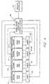
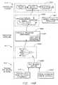
- the overall block diagram of the dynamic system(e.g., the controller, the reactor, the lamps and the sensors) comprises both the controller 100 and the plant or reactor 20 for which the controller is responsible.
- the reactor 20may be exposed to uncontrolled disturbances 104 which influence the reactor state response through disturbance signal input e(t) 124.
- the disturbance signal 124may affect the state of the reactor 20, as measured by the plurality of process control inputs y(t) 116 (or process outputs), in this case comprising an array of the measurements made by temperature sensors 44, 46, 48, 50 at the discrete time variable t.
- the control input 116is provided to the temperature controller 100 through the predictor 108.
- the temperature controllercomprises principally interacting components: the predictor 108, the model 110, a controller or control law processor 112, and is supplied with a command sequence W(t) 122 from a process controller 106 in accordance with the predefined sequence of desired process temperatures.
- the predictor 108computes a sequence of future reactor states y(t+k
- t)are made through any formulation based on the model 126, coupled with the control input 116 and control strategy u(t) 118.
- the predictor output 120extends forward in time from t to t+N, where N is the prediction horizon.
- t)are reciprocally supplied as input to the control law processor 112.
- the control law processor 112computes an optimal control strategy u(t) 118 based on a predetermined control criterion (discussed later), the supplied predictor output 120 and the supplied command sequence W(t) 122.
- the optimal control strategy 118is supplied as a process input to a lamp driver 102 which converts the control signals 118 to electrical power input signals P(t) 114.
- the lamp input signals 114are supplied to the reactor lamps, thereby affecting the radiant heat distribution within the reactor 20.
- the following detailed descriptionprovides a functional explanation of the algorithm used in the model-based predictive controller.
- a brief derivation of the algorithmserves to exemplify the application to temperature control in general, as well as to the preferred embodiments of RTP temperature control.
- the derivationbegins with a single-input, single-output (SISO) process model, subsequently generalized to the multi-input, multi-output (MIMO) case.
- SISOsingle-input, single-output
- MIMOmulti-input, multi-output
- the polynomials C(q -1 ) and F(q -1 )are asymptotically stable polynomials with all their zeros strictly inside the unit circle, and D(q -1 ) is a stable polynomial with its zeros inside or on the unit circle.
- the A(q -1 ) polynomialmay contain unstable process poles, and the B(q -1 ) polynomial may contain nonminimum-phase zeros.
- the C(q -1 ) and D(q -1 ) polynomialsare herein defined as design polynomials.
- An advantageous feature of the present preferred model formulationis the definition and inclusion of polynomials D(q -1 ) and F(q -1 ). Their influence in the model behavior more effectively decouples any correlation between the noise input e(t) and process input u(t). It is believed that such decoupling more accurately reflects the true behavior of a thermal process reactor.
- another advantageous feature of the present preferred model formulationis the definition and use of the filtered signals y f (t) and u f (t).
- the filtered signals y f (t) and u f (t)provide convenient closed-form solutions for the predicted response y(t+k
- t)denotes the predicted value of y(t+k) based on measurements available at time t, i.e., ⁇ y(t), y(t-1), ..., u(t-1), u(t-2), ... ⁇ and (postulated) future values of the process input ⁇ u(t
- Equation (8)plays an essential role in the proper initialization of the difference equation (7).
- t)is re-initialized at each step t and gives consecutively all values in the whole prediction range ⁇ y(t+k)
- t) ⁇ for k1 ...N, where N is the prediction horizon.
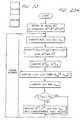
- the structure of the predictor algorithmis substantially as that shown in the dashed block 148 of the flow chart shown in Figure 6.
- the process controlbegins with an initialization block 127 followed by a computation of the forced response gain vector K 129 (to be discussed below in connection with the control law).
- the process input y(t) and output u(t) vectors, as well as the filtered vectors y f (t) and u f (t)are shifted in the time index as indicated by the shift block 128, in accordance with the receding horizon formulation.
- the following process stepsexemplify the predictor structure:
- the predictive controller of the present inventiondetermines the control strategy u(t) which minimizes the cost function H, defined as: subj ect to ⁇ u(t + k
- t)u(t+k
- the cost function Hcomprises terms quadratic in [w(t+k)-y(t+k)] and [u(t+k)-u(t+k-1)].
- the set of terms involving the control input y(t)reflects the predicted controller tracking error, which is desirably minimized with respect to future control moves u(t+k
- the set of terms involving the control strategy u(t)reflects the effort to achieve a given level of tracking error.
- t)can be considered as a superposition of two separate contributions: y(t + k
- i)y 0 (t + k
- t)is the result of past process inputs ⁇ u(t-1), u(t-2), ..., ⁇ assuming that all future control moves are zero (i.e., ⁇ u(t
- t)⁇ u(t+1
- t)...
- t)is the result of future control moves ⁇ u(t
- the gain vector Kis computed in accordance with the foregoing matrix expression. Note that this gain vector has to be computed only once in the non-adaptive case, i.e., the case in which the model parameters remain fixed. This computation can be done in the initialization phase of the algorithm as previously mentioned and shown in process block 128 of Figure 6. Alternatively, the gain vector can be pre-computed off-line and stored in memory. Adaptive extension of the foregoing control law would, in essence, provide for periodic adjustment of the gain vector K.
- a dashed portion 166 of the flow chart in Figure 6corresponds to the predictive controller and is supplied with the process output predictions y(t+k
- the optimum process control input U*(t)is computed using y 0 (t+k
- a decision block 162may test to determine whether the process cycle is complete. If not, then a time-step increment is made in a block 160, which then shifts the set-point matrix in the block 154, as well as process input/output matrix at the block 129.
- model-based predictive control algorithm for multi-input, multi-output (MIMO) systemsis an extension of the SISO case.
- SISOsingle-input, multi-output
- the MIMO control systems modeled by the methods of the present inventionare those characterized by a plurality of input u i (t) variables and output y j (t) variables, where the variable indices i, j run up to the number of respective input and output variables m, n.
- Each output of the MIMOis related to all inputs via a dynamic relationship of the form (1):
- mdenotes the number of inputs
- ndenotes the number of outputs.
- Both m and nare four in the case of the exemplary RTCVD system shown in Figure 1.
- the MIMO multistep predictoris conveniently considered as a consecutively applied predictor of a multi-input, single-output (MISO) model.
- the k-step-ahead predictor for the j th process outputis given by (y f ) j (t + k
- t)(y f ) j (t + k), k ⁇ 0
- the MISO equivalent of Equations (7) and (8)is given by A j (q -1 )D j (q -1 )y j (t + k
- t)C j (y f ) j (t + k
- t)y j (t + k), for k ⁇ 0
- the action produced by the MIMO predictive controllerpreferably minimizes the multivariant cost function analogous to Equations (9) and (10): with respect to ⁇ U i (t+k
- exemplary model parametersmay for example comprise multi-input, multi-output (MEMO) 3rd order polynomial model coefficients defined by with
- a multivariable temperature control system for a rapid thermal process reactorcomprises a temperature sensor array disposed within the process reactor 20.
- the temperature sensorsmay comprise thermocouples or other such equivalents.
- thermocouples 180, 182, 184, and 186 or other such temperature sensorsare connected to the susceptor 24 as previously described in Figure 1.
- the temperature sensors 180, 182, 184, 186are each connected to a data bus via input/output devices such as buffer amplifiers and analog-to-digital (A/D) converters 188, 190, 192 and 194.
- the temperature sensor input/output devices 188, 190, 192 and 194are preferably housed in a temperature data acquisition assembly 172 and are located in the vicinity of the reactor 20 to minimize measurement error.
- the outputs of the A/D converters 188, 190, 192, 194are connected to a data bus 195 which in turn connects to an input/output port 167 of the system temperature controller 170.
- the temperature controller 170comprises a processor 165, a data storage device 169, and data input/output devices 167, 168 which provide hardware/software implementation of the foregoing model-based predictive control algorithm.
- the output of system controller 170are connected to a plurality of lamp drivers 174 via a data bus 198 and provide the lamp drivers with their respective control signals U*(t).
- the plurality of lamp driversmay comprise a bank of SCR power regulators configured in a predetermined manner to supply electrical power to the plurality of lamps in reactor 20.
- the SCR's and lampsare connected to supply radiant energy to the plurality of reactor heat zones in accordance with the preferred radiant heat distribution within the reactor 20.
- the lamp driver outputs P(t) 200are connected to the lamps in accordance with this plan, thereby completing the temperature control loop.
- the temperature sensors 180,182, 184 and 186provide analog signals indicative of the wafer temperature in respective zones center, side, front and rear. As shown in Figure 7, the analog signals are filtered (buffered) and converted to digital signals by the respective A/D converters 188, 190, 192 and 194.
- the digitized temperature information Y(t)is transmitted via the data bus 196 to the system controller 170 which computes the optimal control strategy U*(t) using the foregoing model-based predictive control algorithm and dynamic system model.
- the information necessary for future processing, namely Y(t) and U*(t)is retained in the controller data storage device.
- the system controller 170transmits the control input U*(t) via the data bus 198 to the lamp driver assembly 174 whereupon the control signals U*(t) are distributed to the appropriate SCR packs 171, 173, 175.
- the SCR'sconvert the control signals U*(t) to the lamp drive signals P(t) as previously discussed in connection with the prior art system of Figure 2.
- the lamp drive signals P(t)are transmitted to and distributed among the lamp banks in reactor 20 via the bus 200.
- the lamp banks and lamp drive signalsare configured spatially and temporally, in part by the temperature controller 170, to provide a predetermined spatial and temporal temperature profile over wafer 22.
- the present sectiondiscloses exemplary identification and modeling procedures in order to arrive at a model that accurately describes the dynamics of a multivariable rapid thermal reactor.
- the ensuing modelresides at the core of the model-based predictive temperature control system of the present invention.
- the test arrangement and conditionsare first described, after which the model structure and order selection procedures are discussed.
- the modelis then presented along with exemplary model validation.
- a PC-based Data Acquisition and Control (DA&C) system(not shown) is connected to the RTCVD reactor.
- a software based systemis used to provide the interface between the DA&C hardware and the user.
- the PCis used to control the temperature in the reactor, for example, by using a conventional software-based PID algorithm.
- the DA&C systemis also capable of injecting stimuli, in the form of appropriate test signals, into the system in open-loop mode and detecting the response of the temperature sensors. This open-loop mode comprises a substantial portion of the system operation during the identification experiments.
- the inputs to the system, such as SCR drive signals, and the outputs, such as thermocouple readings,are stored in a data file.
- Identification experiments on the RTCVD reactorare conducted at atmospheric pressure and at a temperature between 600°C-800°C, which is a typical temperature range for polysilicon deposition.
- the controller zone ratio settingsare optimized for steady-state uniformity at 650°C and are maintained constant during the experiment.
- the systemis set for 6" wafer processing.
- a nitrogen purge flow of 20 slmis used throughout the experiment.
- Identification experimentsare also performed in H 2 ambients both at 1 atm and reduced pressure at about 200°C for typical epitaxial deposition conditions.
- the lamp-bank configurationmay be adjusted and in general may differ from that previously shown in Figure 2 in terms of zone distribution and lamp power. Those skilled in the art of reactor design will appreciate that a variety of lamp bank distributions are possible.
- an exemplary lamp distributionmay have all lamps operating at the same nominal power rating of between 3kW and 7kW, with some modification in the distribution of SCR lamp drivers to lamp heating zones.
- the SCR/lamp wiringmay differ between zones to facilitate the power distribution between lamps.
- the preferred lamp bank distribution, power and wiringwill in general depend on the desired thermal processing and reactor geometry. For the purposes of the present preferred embodiments, the preferred design criteria result in a lamp bank configuration having better controllability of the peripheral zones and having reduced temperature differences across the wafer as well as between wafer and susceptor.
- Classical system identificationmakes use of step-signals, pulses or sine waves as test signals for identification purposes.
- the modem equivalent of these signals for identification of multivariable systemsis the Pseudo-Random Binary Signal (PRBS), having a signal level that alternates between two levels at random times.
- PRBSsare allocated peak-to-peak amplitudes of about 1.5 V in order to provide sufficient system excitation.
- Mean signal levelsare chosen to correspond to the steady-state controller output voltage levels corresponding to a temperature of about 650°C.
- the sampling rateis taken to be about 0.5 Hz.
- a one-hour runis recorded.
- the resulting data setis split in two, the first half being used for identification purposes and the second half for model validation purposes. DC-offsets are eliminated from all input and output signals.
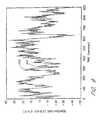
- FIG. 8A and 8BAn exemplary input/output identification data set for the center zone is shown in Figures 8A and 8B, showing the first 200 seconds of system stimuli (Figure 8B) and response ( Figure 8A). Corresponding identification data sets for the front, side, and rear zones are obtained in the same manner and display substantially similar characteristics.
- the next stepis to choose a model structure. Generally, this involves three steps:
- model structurewill likely involve a trade-off between flexibility and parsimony.
- a higher-order modelwill be more flexible, but may lead to unnecessarily many parameters being used to describe the true system.
- a high-order modelis more difficult for on-line use in a model-based controller.
- the principles and guidelines for system modelingare well-known to those skilled in the art of system control. Again, for a more in-depth treatment of the topic of model structure selection one is referred to Ljung (1987).
- the present embodiment of the multi-input, multi-output, model-based predictive controllerutilized a multi-input, multi-output polynomial model in an auto-regressive moving average representation in Equation (15).
- the modelis advantageously considered as a set of coupled linear multi-input, single-output polynomials which allow convenient description of the filter process signals (Y f ) j and (U f ) j (see Equations (17) and (18)).
- the exemplary model parameters provided in Table I belowrefer to a multi-input, multi-output (MIMO) 3rd order polynomial model coefficients defined by with
- model validationincludes simulation, residual analysis, and cross-correlation analysis.
- Residual analysisis used to check whether there is any structural information left unexplained by the model.
- the residualsdifference between model predictions and system output
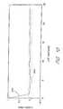
- the curve 304 in Figure 10shows the correlation function of the residual for the center zone output for time lags up to 25 sampling intervals. Dotted lines indicate 99% confidence limits, assuming the residuals are indeed white. Cross-correlation between system inputs and residuals should also show a zero mean with an RMS deviation staying well below the 99% confidence.
- Such behavioras indicated by a curve 306 in Figure 10, should be observed for all cross-correlated quantities, which indicates there is no significant systematic unaccounted input/output correlation.
- the modelis used to predict thermocouple readings using information on past inputs and outputs.
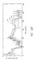
- a fresh data setas used in Figure 9, is also used in the present comparison shown in Figure 11.
- Figure 11shows the system output (center thermocouple) and the one-minute ahead predictions of the system output made using the model predictor. Notice that the predictive capabilities of the model are excellent. Prediction results for the front, side, and rear zones (not included) show similar behavior.
- the model described abovehas been found to provide a very accurate description of system dynamics for an exemplary RTP reactor at atmospheric pressure and in a temperature range of 600-800°C.
- the ARMAX modelis shown to have predictive capabilities particularly advantageous for the present preferred embodiment of a model-based predictive controller.
- the look-ahead feature of the modelcan be used, for instance, to minimize overshoot, thus improving recovery time and minimizing recipe cycle times.
- the precise form of the modelcan vary appreciably without departing from the scope of the present invention. In general, the model form will be dictated by demands on a variety of factors including flexibility, accuracy, sensitivity, robustness and speed.
- One alternative preferred embodimentis to reduce the model order for minimizing computational overhead, without significant loss of accuracy. Additional preferred embodiments comprise:
- a preferred embodiment of the dynamic system modelis capable of tracking and predicting the dynamic behavior of multiple heat zones within reactor 20.
- a preferred multivariant temperature control system of the present inventionis capable of maintaining a predetermined temporal sequence of temperatures for each heat zone of the reactor 20 as exemplified by Figure 12A.
- the solid curves 400, 402, 404, 406 of Figure 12Aindicate the temperature set-point sequence to be followed by independent heat zones: center, side, front and rear respectively.
- the dashed curves 401, 403, 405 and 407are the respective temperature profiles followed by the center, side, front and rear heat zones as a result of action by the temperature controller 170. Time lag between zones is substantially eliminated due to the predictive action by controller 170 operating on all zones in parallel.
- the temperature controller 170supplies the plurality of SCRs with drive signals appropriate for the respective heat zones at a given time.
- the curves 410, 412, 414 and 416correspond to the center, side, front and rear SCR drive signals respectively.
- the SCR drive signals for each zonedisplay very different behavior as determined by the temperature controller 170.
- FIG. 13AAn exemplary demonstration of predictive control versatility is seen in Figure 13A, wherein each zone separately is provided with a temperature step sequence, initially positive then negative.
- the center zone (1)is programmed for a positive temperature excursion, then a negative temperature excursion, followed in succession by the side (2), front (3) and rear (4) zones.
- the controller 170provides the necessary control signals concurrently to all four zones such that each zone, independently, maintains the programmed temperature profile. Note that while a specific zone is ramped up or down, the other zone temperatures are substantially unchanged, indicating the substantially complete decoupling of heat zones as a result of the model-based predictive control.
- the exceptional temperature control displayed by the preferred embodimentis also manifest in the control signals.
- the controllercompensates by driving each zone with a signal appropriate to maintain the prescribed temperature profile, both spatially and temporally.
- the model-based predictive control system of the present inventionimplemented in a rapid thermal process reactor, substantially optimizes process cycle time as well as spatial temperature uniformity.
- the linear model disclosed abovecan be further enhanced by using a nonlinear model of the process reactor.
- a preferred method for implementing the nonlinear modelinvolves the use of neural networks.
- a preferred embodiment of the neural network based nonlinear predictive controlleris a Neural Extended Prediction control (NEPco) neural model based predictive controller for the susceptor temperature control of the ASMA reactor.
- NEPcoNeural Extended Prediction control
- FIG. 14Ais a block diagram that illustrates a fabrication system 1400.
- a recipe block 1401provides input into a NEPco process block 1402.
- the NEPco process 1402outputs control signals to one or more SCR's that operate one or more lamps 1403.
- the lamps 1403provide heat to a reactor 20 which is represented by a reactor process block 1404.
- a group of unmeasurable outputs from the reactor process block 1404are the wafer surface temperatures 1405.
- a group of measurable outputs from the reactor process block 1404are the susceptor temperatures 1406.
- the susceptor temperaturesare fed back into the NEPco process block 1402 to facilitate temperature control of the wafer 22 and the susceptor 24.
- the temperature of the wafer surfaceis of major importance for the deposition process. However, the wafer temperature is not measured during normal operation. The only signals which are directly measured for control purposes are the susceptor temperatures. Experiments have indicated that these susceptor temperatures provide a reasonable approximation of the unknown wafer temperature distribution. Experimental results indicate that good susceptor control alone is not sufficient to obtain very tight wafer control.
- the NEPco embodiment of the present inventiondiscloses a procedure for improved control of the susceptor temperature signals 1406. This improvement provides the immediate benefits of improving the temperature control of the susceptor 24 and therefore the wafer 22, and it sets the stage for improvements using various models based on the soft sensor principle.
- Figure 14Billustrates an overview of the hardware, software, and conceptual components that comprise the system 1400. The reader is urged to refer back to Figure 14B before reading each section below in order to place the section about to be read in context.
- Figure 14Bshows a three layer structure of elements that comprise the system 1400. Lower levels in the structure represent, at greater levels of detail, the internal elements of the upper layers.
- a controller system layer 1410comprises the system 1400 and is the topmost level of the system 1400. Working downward, the next level is the predictive modeling level 1411 which comprises a predictor process 1500, a series parallel predictor 1801, a parallel predictor 1800, and a neural network 1600.
- the lowest of the three levelsis a training layer 1412 which comprises a pseudo least squares (PLS) block 2300, a pulsetest experiment block 1900, and an initial estimate block 2400.
- PLSpseudo least squares
- the predictor process 1500is shown as being part of the NEPco process block 1402.
- the series-parallel predictor 1801 and the parallel predictor 1800are shown as being different implementations of the predictor process 1500.
- a unit step response 2100is shown as being an internal component of the parallel-predictor 1800.
- the neural network 1600is shown as being a part of the parallel predictor 1800.
- the PLS training method block 2300is shown as applying to the neural network 1600.
- the pulsetest experiment block 1900 and the initial estimate block 2400are shown as being inputs to the PLS training method block 2300.
- Figure 15illustrates a block diagram of the nonlinear process model 1500.
- a process input u ( t ) 1501is the sole input to a model process block 1502.
- the process input 1501appears in the equations as u ( t ) and is typically a voltage to the lamp driver SCRs.
- the model process block 1502exhibits a nonlinear transfer function f true.
- a model output x ( t ) 1504is an output of the process block 1502.
- the model output x ( t ) 1503appears in the equations that follow as x ( t ) and is typically a temperature expressed in °C.
- the model output x ( t ) 1503 and a process disturbance n ( t ) 1503are added together at a summing junction 1506.
- the output of the summing junction 1506is a process output y ( t ) 1505.
- the process disturbance 1503is expressed in the equations that follow as n ( t ) and is typically expressed as a temperature in °C.
- the process output 1505is expressed in the equations that follow as y ( t ) and is typically the susceptor temperature measurements expressed as a temperature in °C.
- the process disturbance n ( t ) 1503includes all effects in the process output y ( t ) 1505 which do not come from the model output x ( t ) 1504.
- the process disturbance n ( t ) 1503is a fictitious (unmeasurable) signal which includes such disturbance effects as deposition, gas flow, measurement noise, model errors, etc. These disturbances typically have a stochastic character with nonzero average value.
- the model output x ( t ) 1504represents the effect of the power input u ( t ) 1501 on the susceptor (thermocouple) temperature. This is an unmeasurable signal, as only the combined effect of control action plus disturbances is measurable via the thermocouple sensors 44, 46, 48, and 50.
- the relationship between the input u ( t ) and the output x ( t )is a dynamic relationship in that the present temperature x ( t ) does not depend on the present input u ( t ), but on the previous temperatures ⁇ x ( t -1), x ( t- 2), ... ⁇ and the previous inputs ⁇ u ( t -1), u ( t- 2), ... ⁇ .
- experimental measurementsshow that for a typical ASMA reactor, the relationship between u ( t ) and x(t) is also strongly nonlinear. For example, in one experiment the effect of a specific power input variation on the resulting temperature was found to be quite different around 800°C as compared to 1100°C. These temperatures are by way of example only since different reactors will exhibit different properties.
- the function f veinis implemented as a neural network.
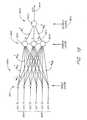
- Figure 16illustrates a typical typical neural network.
- the set of past model outputs 1604 ⁇ x ( t -1), x ( t -2), ... ⁇ and the set of past model inputs ⁇ u ( t -1), u ( t -2),... ⁇are shown as inputs to a layer of input neurons 1601.
- the input neurons 1601are connected to a layer of hidden neurons 1602 such that every one of the input neurons 1601 is connected to every one of the hidden neurons 1602.
- the hidden layer 1602contains three hidden neurons 1610, 1611, and 1612.
- the hidden neurons 1602have outputs labeled z 1 ...z i ...
- z nsuch that z 1 is the output of the first hidden neuron 1610 and z n is the output of the last hidden neuron 1612.
- the connections between the input neurons 1601 and the hidden neurons 1602are labeled w [1] / ij where i indicates the hidden neuron having the output z i and j indicates which of the input neurons 1601 is being connected.
- the superscript [1]indicates the connection starts from the first layer of neurons. All of the hidden neurons 1602 are connected to an output neuron 1613 by connections labeled w [2] / i where i indicates the hidden neuron output z i that is being connected to the output neuron 1613.
- the superscript [2]indicates the connections from the second layer of neurons of neurons.
- the input neurons 1601are non-active neurons in that the neurons do not perform any computation, they only distribute the input signals to the hidden neurons 1602.
- a third order modelis used, meaning the six input neurons 1601 corresponding to the three previous values of x ( t ), namely x ( t -1), x ( t -2) and x ( t -3), and the three previous values of u ( t ), namely u ( t -1), u ( t -2), and u ( t -3), are provided as inputs to the input layer 1601.
- the hidden layerpreferably contains nonlinear sigmoid-type neurons.
- Sigmoid neuronsare well known in the art (see e . g ., James A. Freeman and David M. Skapura, "Neural Networks” Addison Wesley, 1991).
- the biases b [1] / 1are used to compensate for an offset in the process model. The offset arises from the fact that, in reality, the output x ( t ) is not necessarily zero when the input u ( t ) is zero.
- Figure 19shows a simple neural network 1900.
- the simple neural network 1900comprises a single hidden neuron 1904 of the sigmoid type.
- the hidden neuron 1904has a group of inputs 1901 comprised of model outputs x 1 ( t -1), x 1 ( t -2), and x 1 ( t -3).
- the hidden neuron 1904also has a group of model inputs 1902 comprised of model inputs u 1 ( t -1), u 1 ( t -2), and u 1 ( t -3).
- the hidden neuron 1904also has a group of model inputs 1903 comprised of model inputs u 4 ( t -1), u 4 ( t -2), and u 4 ( t -3).
- Figure 19further illustrates that the hidden neuron 1904 has inputs comprised of model inputs u 2 ( t -1), u 2 ( t -2), u 2 ( t -3), u 3 ( t -1), u 3 ( t -2), and u 3 ( t -3).
- An output of the hidden neuron 1904feeds a linear output neuron 1905.
- the neural network 1900has a single output x 1 ( t ) 1906.
- the output layercontains the single linear output neuron 1613.
- the output of the output neuron 1613is computed as follows:
- the weight and bias of the output neuronshould be identified together with those of the hidden-layer neuron. In fact, all of the weight and bias parameters together constitute the model of the unknown process dynamics.
- t )is based on:
- the two most preferred configurations for modeling the ASMA reactorare a parallel model and a series-parallel model.
- the nonlinear model 1502be based upon a neural network.
- the preferred embodimentuses a neural network.
- the modelwill assumed to be implemented using neural network, with the understanding that other (non-neural network) implementations are possible.
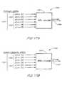
- Figures 17A and 17Bshow block diagrams of two common recursion networks.
- Figure 17Ais a block diagram of the parallel model network.
- the model 1701is shown as a neural network (NN) process block with an input vector 1707 and a single output x ( t + k )
- the input vector 1707has a group of inputs 1702 comprising model outputs 1504.
- the model outputs 1504comprise ( x ( t+k- 1
- the input vector 1707has a group of process inputs 1703 comprising process inputs 1501.
- the inputs 1501comprise ( u ( t+k -1
- Figure 17Bshows the series-parallel model neural network as an NN-block 1751, which is a process block with an NN-input vector 1757 and a single output x ( t+k )
- the NN-input vector 1757has a group of inputs 1752 comprising process outputs 1505.
- the inputs 1505comprise ( y ( t+k -1
- the NN-input vector 1757also has a group of inputs 1702 comprising process inputs u ( t+k -1
- the parallel modelalso known in the art as the independent model, preferably should be used only for stable processes.
- the series-parallel modelcan also be used for unstable processes.
- the disturbance model C(q -1 )/D(q -1 )should be chosen differently. Both models are useful for the the ASMA application; however, the parallel model is preferred and so it is described in greater detail herein.
- t )is computed using the NN input vector 1707 [ x ( t -1) x ( t -2) x ( t -3) u ( t -1) u ( t -2) u ( t -3)], which contains values from the past, thus known at time t . Notice that x ( t ) ⁇ x ( t
- x ( t )is computed using the NN-model 1701.
- t )C ( q -1 D ( q -1 ) ) n f (t + k
- t)- d 1 ⁇ n(t + k -1
- the signal values in the right-hand sidenamely n ( t
- t )0.
- t )is then used in the right-hand side, together with n f ( t+ 2
- t )0 in order to compute n ( t+ 2
- Figure 18is a flowchart that illustrates the process for computing a new set of predictions for n ( t+k
- Figure 20shows a two-axis plot having an x-axis 2001 showing, having a y-axis 2002 showing a curve 2003 representing u , a curve 2004 representing y, and a horizontal line 2005 representing the curve w / r .
- the y-axis 2002is positioned on the x-axis 2001 at time t .
- time values on the x-axis 2001 that lie to the right of the y-axis 2002represent the future, such as u ( t+k
- points on the x-axis 2001 that lie to the left of the y-axis 2002represent the past.
- the ultimate objective of the SISO controlleris to find the control input u ( t
- t )u ( t + k
- t )⁇ r ( t + k -1
- t ), for k1... N 2 , ; and r ( t
- t )y ( t ).
- the design parametersare and preferred values are:
- t )can be considered as the sum of two separable effects, namely the free response and the forced response, where: y ( t + k
- t )y free ( t + k
- t )is a direct result of: (1) the effect of past control ⁇ u ( t -1), u ( t -2),... ⁇ as if ⁇ ⁇ u ( t
- t )⁇ u ( t+ 1
- t )...
- t )can be computed with the procedure described in Figure 18, with u ( t
- t )u ( t+ 1
- t )is a direct result of: (1) the effect of future control actions ⁇ ⁇ u ( t
- t )is the effect of a sequence of step inputs 1920 having:
- the parameters g 1 , 2 , ..., g k , ..., gN 2are the coefficients of the unit step response of the system.
- the unit step responseis the response of the system output for a stepwise change of the system input (with amplitude 1).
- the unit step responseis different for each operating point.
- t )means the future setpoint as postulated at time t . If the setpoint is preprogrammed, the future setpoint values w ( t+k ) can be used for w ( t+k
- y 1 ( t )x 1 ( t )+ n 1 ( t )
- y 2 ( t )x 2 ( t )+ n 2 ( t )
- x 1 ( t )f 1 [ x 1 ( t -1),..., x 1 ( t -3), u 1 ( t -1),..., u 1 ( t -3), u 2 ( t -1),..., u 2 ( t -3)]
- x 2 ( t )f 2 [ x 2 ( t -1),..., x 2 ( t -3), u 1 ( t -1),..., u 1 ( t -3), u 2 ( t -1),..., u 2 ( t -3)]
- the objectiveis to find the control inputs u 1 ( t
- step responsescan be defined, describing the effect of a stepwise change of each of the two inputs on each of the two outputs.
- the coefficients of the step response of input j to output iare denoted by: ⁇ g ij / 1 g ij / 2 g ij / 3 ⁇
- step responsesrelating each of the four SCR inputs to each of the four susceptor temperature sensor outputs 44, 46, 48, and 50.
- Figure 21is a flowchart illustrating the steps necessary to compute the step responses.
- the processbegins at a loop control block 2101.
- a loop counter nis set to the value 1, representing the first input.
- the processthen advances to a process block 2102 where u 1 (t+k
- t) ⁇are the free responses of the neural networks and are used to calculate the system free responses y (t+k
- t)x [0] (t + k
- Model Based Predictive Controlis a control strategy which relies heavily on the availability of the model 1502.
- the preceding sectionshave largely assumed the existence of the model 1502, preferably based on a neural network 1600, without elaborating how the model is generated.
- This sectionbegins with a brief discussion of the advantages of using a neural network 1600 as the basis for the model 1502 and then describes how the model is generated. Since the model is based on a neural network 1600, generation of the model is largely a process of training of the neural network. Training the neural network corresponds to the training layer 1612 of Figure 14B, and requires the PLS training method 2300, the pulsetest experiment 1900, and the initial estimates 2400 shown in that Figure.
- Modeling of a physical system for control purposesrequires the finding of a mathematical relationship (a model) between the system's inputs and outputs.
- a mathematical relationshipentails construction of a mathematical model that describes the effect of the SCR-signals (the inputs) on the susceptor thermocouple signals 44, 46, 48, and 50 (the outputs).
- the modeldepends on the underlying physical characteristics of the process, which in this case, is mainly a thermal process.
- the preferred approachis to use a black box model (a neural network) and train that network using experimental data obtained from the reactor during an identification experiment.
- the obtained modelshould be quite general in that it should be valid for other experimental data than those used during the identification experiment, as long as the reactor is operating in similar conditions of temperature range and reactor configuration. If essential changes occur, the process will generally need to be re-modeled.
- the modeling of a typical ASMA reactortakes less than 1 hour, including the required identification experiment.
- a Pseudo Least Squares (PLS) methodis used to train the neural network 1600 as a nonlinear model for the ASMA reactor.
- the NN-modelis then further used in the NEPco predictive control strategy as shown in Figure 14B.
- the training procedureconsists of the following general steps of:
- the pulsetest experiment 1900 and PLS method 2300are described in detail below.
- the software necessary to perform the modeling tasksis implemented using MATLAB®.
- the preferred embodimentcould be re-coded in other languages without difficulty.
- the ASMA reactoris a system with four inputs (SCR-signals) and 4 outputs (thermocouple signals) as listed in Table II.
- the four input ASMA reactor systemThe inputs are denoted as: The outputs are denoted as: u 1 (t): center SCR signal (0-5V) y 1 (t): center thermocouple signal (°C) u 2 (t): front SCR signal (0-5V) y 2 (t): front thermocouple signal (°C) u 3 (t): side SCR signal (0-5V) y 3 (t): side thermocouple signal (°C) u 4 (t): rear SCR signal (0-5V) y 4 (t): rear thermocouple signal (°C)
- the reactoris computer-controlled and all signals are sampled on a discrete-time basis.
- Training the neural network 1600requires that a set of modeling coefficients ⁇ W [1] , b [1] , W [2] , b [2] ⁇ be generated.
- the modeling coefficientsdepend on a sample period, SamplePeriod .
- the SamplePeriodis 2 seconds.
- the numerical values in the modeldepend on this sampling period. This means that the control, which is based on this model, should also be executed with a sampling period of 2 seconds. The sample period can be changed without ill effect, but if the control sampling period is changed, remodeling to compute a new set of coefficients is prudent.
- a characteristic of the modelis that each output ⁇ y 1 ... y 4 ⁇ depends on all four inputs ⁇ u 1 ... u 4 ⁇ .
- the pulsetestwhich consists of sending consecutively a pulse in each SCR input and measuring each thermocouple reaction. In order to cover the entire nonlinear operating range of the reactor (e.g. 800°C to 1100°C), the test is repeated at several base values of the SCR inputs.
- a parameter Durationdetermines how many samples each pulse lasts. In a preferred embodiment, the Duration is five samples (10 seconds).
- a parameter BaseValuesis a row vector containing one or more base values for the SCR inputs, in volts (V).
- Typical BaseValuesare [0.8, 1.3, 2.0], corresponding approximately to reactor temperatures [800, 950, 1100] (in °C). More than three base values can be used, leading to higher accuracy, however, this requires a correspondingly longer experiment.
- the pulsesare executed successively for each base value. The time between two pulses, specified as a number of samples in a parameter Period, depends on the settling time of the reactor. For a common reactor, typical values for the parameter Period are between 60 and 120 samples. None of these parameter values are critical and wide variation in values will yield acceptable results.
- the result of the pulsetest experiment 1900is a dataset containing all input and output samples of the pulsetest experiment. This dataset can be used by the modeling software to train the NN model.
- the input layeris a layer of non-active neurons.
- the non-active neuronsdo not perform any computation, they only distribute the input signals to the neurons in the hidden layer.
- the outputs z iare computed as follows:
- the biasesare desirable in order to compensate for the fact that the output y is not necessarily zero when the input x is zero.
- the output layercontains a single linear neuron.
- the output yis computed as follows:
- training the NNinvolves estimating the weights W and biases b .
- a set of training data from the pulsetest experimentis used.
- T(k)are target values and N is the number of samples.
- the PLS methodhas the advantages of simplicity, ease of programming and fast training speed.
- the PLS methoddescribed in more detail below, involves finding an initial set of estimates, and then using an iterative procedure to refine the initial estimates. Briefly, the iterative procedure involves starting at the hidden layer of neurons and working forward, thought the NN, towards the output neuron, refining the parameters W and b for each layer.
- the following sections hereinpresent the PLS method and a procedure for implementing the method.
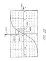
- Figure 22illustrates the sigmoid function.
- Figure 22shows the sigmoid function plotted on an X axis 2201 ranging from -3 to 3, and a Y axis 2202 ranging from -1 to 1.
- a neuron input n 2203 and corresponding neuron output z 2206are shown on the X axis 2201 and Y axis 2202 respectively.
- Slightly displaced from the neuron input n 2203 and corresponding output z 2206are a fictitious neuron input n * 2204 and a corresponding fictitious neuron output z * 2205.
- FIG. 23is a flowchart illustrating the PLS procedure.
- the PLS methoddoes requires an initial estimate for each of the vectors. Since there are many methods that can be employed to develop the initial estimates, the process of developing the estimates is not, strictly speaking, a part of the PLS method. Therefore, the PLS method presented here merely assumes that an initial estimate is available. A preferred method for developing the initial estimates is described below.
- a decision block 2313if V new is less than V old then proceed to a process block 2314, otherwise jump to a decision block 2315.
- the process block 2314replace the old values of W [2] , b [2] , y ( k ) and V old with the new values of W [2] , b [2] , y ( k ), and V new .
- the result of the procedure in Figure 23is a new set of parameters [ W [1] , b [1] , W [2] , b [2] ] and related network internal variables ⁇ N (k) , Z (k) ⁇ and output values ⁇ y(k) , V ⁇ .
- the whole procedurecan be repeated a number of times until the decrease of V is zero or less than a specified small value.
- the choice of a good set of initial valuesis of utmost importance in order to reduce the number of iterations and to prevent getting stuck in local minima.
- a preferred approach to the initialization problemis to start from the parameters of the linear model:
- the linear and non-linear models disclosed abovecan be further enhanced by adding a softsensor model to the basic MBPC fabrication system 1400.
- the temperature of the wafer surfaceis of major importance for the deposition process.
- the point-to-point wafer temperatureis not measured during normal operation.
- the susceptor temperaturesgive a reasonable approximation of the unknown wafer temperature distribution.
- good susceptor control aloneis not sufficient to obtain very tight wafer control.
- Temperature transientsare typical situations in which wafer and susceptor temperatures might differ considerably. This is due to the different mass (heat capacity) of susceptor and wafer. Good susceptor control with no (or very low) temperature overshoot does not necessary lead to wafer control with low overshoot. Moreover the front 46, side 48 and rear 50 susceptor setpoints require the specification of an offset with respect to the center 44 susceptor setpoint in order to result in a good temperature uniformity over the wafer surface. In the prior art, these offsets are found by trial and error.
- the more more systematic method and apparatus presented herewhich solves the above problems, is the use of MBPC combined with the softsensor principle.
- the conceptis that the unmeasured wafer temperature can be replaced by the outcome of a model describing the dynamic relationship between susceptor and wafer temperatures.
- this softsensor modelis identified using data obtained from experiments with an instrumented wafer.
- Figure 24is a block diagram that illustrates an extension of the basic fabrication system 1400 to a softsensor fabrication system 2400.
- a recipe block 2401provides input into a setpoint generator block 2410.
- An output of the setpoint generator blockprovides input to a MBPC process block 2402 and a softsensor process block 2412.
- An output of the softsensor process block 2412is a wafer estimate 2414.
- the output of the wafer estimate 2414is fed back into the setpoint generator block 2410.
- the MBPC process block 2402outputs control signals to a reactor and lamp system 2404.
- a group of unmeasurable outputs from the reactor process block 2404are the wafer surface temperatures 2405.
- a group of measurable outputs from the reactor process block 2404are the susceptor temperatures 2406.
- the susceptor temperaturesare fed back into the MBPC process block 2402 to facilitate temperature control of the wafer 22 and the susceptor 24.
- the recipe 2501is used as setpoint for the susceptor temperature. Then, in the basic control structure, the recipe is interpreted as setpoint for the wafer temperature. The setpoints for the susceptor control are then computed internally in the control strategy, using the softsensor principle.
- a model, describing the dynamic relationship between susceptor setpoints and wafer temperatures,is identified using an instrumented wafer.
- the instrumented waferis a special wafer which has temperature sensors on the surface of the wafer 20. This allows actual wafer surface temperatures to be measured. These measured values are used to obtain modeling coefficients for the softsensor process block 2412.
- the softsensor process block 2412being a part of the control software, can be used to generate an estimate of the wafer temperature.
- the setpint generator 2410is a PID filter and the softsensor block 2414 is a linear FIR filter.
- the resultis that the wafer temperatures, and not the susceptor temperatures, are controlled towards the values specified in the recipe.
- This procedurealso computes, automatically, the necessary offsets for center 44, front 46, side 48 and rear 50 susceptor setpoints in order to bring all wafer temperatures close to the recipe. This leads to better uniformity of the temperatures over the wafer surface.
Landscapes
- Engineering & Computer Science (AREA)
- Artificial Intelligence (AREA)
- Evolutionary Computation (AREA)
- Physics & Mathematics (AREA)
- General Physics & Mathematics (AREA)
- Automation & Control Theory (AREA)
- Health & Medical Sciences (AREA)
- Computer Vision & Pattern Recognition (AREA)
- Medical Informatics (AREA)
- Software Systems (AREA)
- Remote Sensing (AREA)
- Feedback Control In General (AREA)
Description
- The invention relates to automatic feedback control of thermal processing. Inparticular, the invention pertains to model-based predictive temperature control ofthermal process reactors such as used in semiconductor processing.
- Until recently, most of the high temperature processing necessary for integratedcircuit fabrication was performed in hot-wall, resistance-heated batch reactors:Controlling the wafer temperature uniformity (within-wafer, point-to-point) in thesereactors was generally not considered an issue, because the reactors were substantiallyisothermal. The down-boat (wafer-to-wafer) temperature uniformity could be controlledeffectively by dividing the cylindrical heating coil into several zones, each with its owntemperature sensor controller and power supply. The outer zones were typicallyadjusted to compensate for heat losses at the furnace ends. Independent, single-loop,off the-shelf PID controllers suffice for these purposes. The trend to larger waferdiameters, the demanding uniformity requirements for ULSI applications, and thedemands for reduced thermal budget all led to an increased use of single-wafer processreactors. For commercially feasible throughput, it is highly desirable to minimize theprocess cycle time by heating substantially only the wafer and its immediateenvironment. In many cases, single-wafer reactors are of the cold-wall or warm-walltype, in which quartz or stainless steel process chambers are water or air cooled. Undersuch circumstances, the system is no longer isothermal and temperature uniformitycontrol becomes an issue of considerable concern and technical difficulty. A recenttechnical review of the field is provided in "Rapid Thermal Processing Systems: AReview with Emphasis on Temperature Control," F. Roozeboom, N. Parekh,J. Voc.Sci. Technol. B 8(6), 1249-1259, 1990.
- Specific physical process characteristics serve to exemplify the need for precisetemperature uniformity. Homo-epitaxial deposition of silicon should be performed in amanner which minimizes crystalline growth defects, such as lattice slip. Such defects areinduced by thermal gradients in the wafer during high temperature processing,becoming more sensitive to gradients as temperature increases. For example, whilegradients of about 100°C across an 8-inch wafer may be tolerable at a processtemperature of 900°C, respective gradients of only 2-3°C are allowable at processtemperatures of 1100°C. There is some experimental evidence to indicate that gradientsof approximately 10°C may be tolerable for a few seconds. The deposition ofpolycrystalline silicon (polysilicon) typically takes place at 600-700°C where as a ruleof thumb a 2% uniformity degradation is incurred for every degree of temperaturegradient. Moreover, in heterodeposition processes such as polysilicon deposition,multiple reflections and optical interference within the deposited overlayers can give riseto emissive or absorptive changes with overlayer thickness, exacerbating the problem ofmaintaining temperature uniformity (J.C. Liao, T.I. Kamins, "Power Absorption DuringPolysilicon Deposition in a Lamp-Heated CVD Reactor, J. Appld. Phys., 67(8), 3848-3852(1990)). Furthermore, patterned layers can also lead to variations in lightabsorption across the wafer, creating local temperature gradients. (P. Vandenabeele, K.Maex, "Temperature Non-Uniformities During Rapid Thermal Processing of PatternedWafers,"Rapid Thermal Processing, SPIE, Vol. 1189, pp. 84-103, 1989).
- The aforementioned factors complicating the control system design are not onlymanifest for rapid thermal chemical vapor deposition (RTCVD) systems, but apply tothermal processing (TP) systems in general, where the need for precise process controlis balanced by the demand for minimal process cycle times. The generally short processcycle times and fast dynamics of the single-wafer systems render dynamic control oftemperature uniformity a necessity of considerable technical difficulty. The radiantheating systems used for rapid wafer heating comprise either arc lamps or banks oflinear tungsten-halogen lamps divided into several independently-controllable heatingzones. The wafer itself, in principle, represents a complex thermal system whoseinteraction with the radiant energy is inherently nonlinear. Furthermore, since therequirements for power distribution over the wafer are different for dynamic compared to steady-state uniformity, it does not suffice to deduce the required power settings froma wafer temperature measurement at a single point. In general, multiple sensors arerequired to measure and maintain a uniform temperature distribution over the wafer.These considerations render temperature control an essentially multi-input, multi-output(MIMO) or multivariable problem. Due to the large interaction between zonesinherently present in radially heated systems, the conventional control techniques, forexample, using single-loop, coupled or master-slave type PID control, cannot beexpected to provide thermal process reactor systems with the required controlspecifications for all operating conditions. Conventional PID control techniques aresusceptible to lag, overshoot and instability at the desirable process rates, and thereforebecome limiting factors in single-wafer process reactors. Thus, there is a clear need inelectronic materials processing for systems which can maintain precise, dynamicmultivariant control while providing commercially viable wafer throughput.
- The foregoing discussion has clearly outlined the need for effective uniformitycontrol in thermal process reactors using a multivariable approach. This view isendorsed by many authors. See, for instance, several contributions in theRapid Thermaland Integrated Processing Symposium, ed. J.C. Gelpey, et al.,Mater. Res. Soc. Symp.Proc., Vol. 224, 1991. In particular, articles by Moslehi et al. (pp. 143-156), Apte, et al.(pp. 209-214), and Norman et al. (pp. 177-183), discuss various aspects of multivariabletemperature control. Several attempts to develop models for RTP and RTCVD systemsare reported in the literature. Two examples, Norman and Gyurcsik, et al., developeddifferent models, both using a first-principles approach, and applied the models touniformity optimization (S.A. Norman, "Optimization of Wafer TemperatureUniformity in Rapid Thermal Processing Systems," ISL Tech. Rep. No. 91-SAN-1,Subm. to IEEE Trous. on Electron Devices, 1991; R.S. Gyurcsik, T.J. Riley, R.Y.Sorrel, "A Model for Rapid Thermal Processing: Achieving Uniformity Through LampControl," IEEE Trans. on Semicon. Manf., Vol. 4(1), 1991). The model of Norman(1991) consists of two components. The first component models the (two-dimensional)heat balance of the wafer and is used to compute the steady-state wafer temperatureprofile for a given heat flux from the lamps. The second component models the heatflux from the lamps as a function of the individual lamp powers. A least-squares method is used to fit a quadratic relationship between the desired temperature at discreteradial positions on the wafer and the flux density due to the lamps. Next, the lampmodel is used to determine optimal relative power settings for the lamps thatapproximate the required flux. This method only applies to the uniformity control insteady-state, i.e., constant input. However, Norman, et al. (1991), consider not only thesteady-state optimization problem, but also the problem of designing an optimaltrajectory. For this purpose the dynamic model is a finite-difference approximation tothe one-dimensional heat equation, including the effects of conduction in the wafer,convective heat loss from the wafer, and radiative transfer. A minimax solution ischosen for the steady-state uniformity optimization and trajectory following.
- Dynamic system modeling is an essential ingredient of predictive control laws,which provide the fundamental structure for a unique class of contemporary controlalgorithms. In essence, system or plant control strategies are based on predicted futureplant behavior predicated on a suitably accurate dynamic plant model. The futurecontrol strategies are not static and do not extend arbitrarily to future time slots; butrather are periodically updated in accordance with the plant model in a so-calledreceding horizon fashion. For a number of years, predictive control has been the subjectof extensive research and development. Indeed, predictive control is the central themebehind the benchmark works of Cutler and Ramaker in their Dynamic Matrix Control(DMC) algorithm (C. Cutler, B.L. Ramaker, "Dynamic Matrix Control―A ComputerControl Algorithm,"Joint Automatic Controls Conference Proceedings, San Francisco,1980) and Richalet, et al., in their Model Algorithmic Control (MAC) algorithm (J.A.Richalet, A. Rault, J.D. Testud, J. Papon, "Model Predictive Heuristic Control:Application to Industrial Processes,"Automatica, Vol. 14, No. 413, 1978). Furtherpredictive and adaptive characteristics are incorporated by R.M.C. de Keyser, et al.,"Self-Tuning Predictive Control,"Journal A, Vol. 22, No. 4, pp. 167-174, 1981; andmore recently by Clarke, et al., in their Generalized Predictive Control (GPC) algorithm(D.W. Clarke, C. Mohtadi, P.S. Tuffs, "Generalized Predictive Control. Part I: TheBasic Algorithm,"Automatica, Vol. 23, No. 2, pp. 137-148, 1987). Much of thecontemporary control work in the literature is to some extent based on these approaches.
- In DMC and other similar approaches, plant models are identified and cast in theform of deterministic impulse-response or step-response models. While these modelforms are well-understood, they are often computationally cumbersome and presentsignificant compromises between accuracy and response for long-range modelpredictions. Further, DMC appears to be incapable of handling non-minimum phaseand open-loop unstable plants. A significant redeeming feature of DMC is that of thereceding horizon, after which control increments are assumed to be zero. Thisadvantageous assumption is incorporated in GPC, which in various derivations alsoutilizes extensions of Auto-Regressive Moving Average (ARMA) plant models such asCARMA or CARIMA (Controlled Auto-Regressive Moving Average, CAR-integrated-MA).The ARMA plant models are generally represented by expressions involvingpolynomials A, B and C of the time-shift operator q-1. The shift operator q-1 acts on afunction of a discrete time variable f(t), such that q-1f(t) = f(t-1) and in general q-uf(t) =f(t-u). The model polynomials A, B and C act on process inputs u(t), process outputsy(t) and process disturbances e(t) such that:
- Nevertheless, in spite of the recent effort to develop new, useful multivariantcontrol techniques, until now there has been little success in applying them to thedemanding conditions imposed by commercial thermal process reactors. The onlyapparent successes to date has involved the use of physical models rather than the blackbox models employed herein (see e.g. Cole Porter et. al., "Improving Furnaces withModel-Based Temperature Control",Solid State Technology, November 1996, page119).
- An example of a temperature controlled wafer temperature reactor is given inUS-A-4 975 561, which describes a reactor utilising radiant heating from heatinglamps which are controlled by a simple comparator. A more complex system has beendescribed by T. Breedijk et al ("A model predicitive controller for multivariabletemperature control in rapid thermal processing", Proceedings of the AmericanControl Conference, San Francisco, June 2-4 1993, vol. 3, 2 June 1993, pp 2980-2984,XP000410804 Institute of Electrical and Electronics Engineers). This includes aprocess chamber with a wafer, a four-zone tungsten halogen illuminator to provideheating, and four thermocouples. A multivariable nonlinear model predictivecontroller is used.
- A. Karaduman et al ("Nonlinear model predictive temperature control of abatch polymerization reactor", Advances in Process Control, 27 September 1995, pp203-210, XP002081211 UK) describe an alternative temperature reactor, in the formof a tank reactor for wet chemical polymerization. A batch stirred tank reactor has acooling jacket, a manually controlled elecric heater, and equipment for onlinecomputer control. The reactor temperature is controlled by manipulating the flow rateof cooling water into the jacket during a heating generating phase of the reaction.
- Predictive control has applications in other fields. For example, US-A-5 301101 describes a heating and air conditioning system for maintaining the temperatureof a building, which uses a linear process model to achieve the predictive control.
- It is an object of the present invention to provide a method and apparatus for amore effective temperature control system in multivariant thermal processes.
- Accordingly, a first aspect of the present invention is directed to a temperaturecontrolled thermal process reactor comprising:
- a reaction chamber enclosing an object to be heated;
- a plurality of sources of thermal energy which heat said object;
- a plurality of thermal sensors, each sensor configured to measure a sensortemperature, each sensor temperature related to an actual temperature of said object,where each thermal sensor provides an output signal representative of said sensortemperature, and where each of said sources of thermal energy affects each of saidsensor temperatures; and
- a model-based predictive temperature controller comprising a nonlinearprocess model, said temperature controller configured to receive said output signalsand control said sources of thermal energy in response to said output signals toproduce a selected spatial and temporal distribution of heat energy to maintain arelatively uniform actual temperature on said object, said model-based predictivetemperature controller comprising a multivariable thermal process model that relatesmultivariable process input thermal energy to multivariable process outputtemperature, a prediction calculator that uses said thermal process model to calculate apredicted nominal temperature output over a future time period, and a controlcalculator that uses said predicted nominal temperature output to calculate an optimumcontrol strategy to control said sources of thermal energy.
- A second aspect of the present invention is directed to a method of controlling athermal process in a reactor, the reactor comprising a reaction chamber enclosing anobject to be heated, a plurality of sources of thermal energy which heat said object, aplurality of thermal sensors, each sensor configured to measure a sensor temperaturerelated to an actual temperature of said object, where each thermal sensor provides anoutput signal representative of said sensor temperature, and where each of said sourcesof thermal energy affects each of said sensor temperatures, and a model-based predictive temperature controller comprising a nonlinear process model, the methodcomprising the steps of:
- measuring one or more process output temperatures;
- predicting a plurality of future process output temperatures by using the nonlinearthermal process model;
- using said one or more measured process output temperatures and said predictedfuture process temperatures to calculate an optimum process input control strategy bycomparing one or more of said predicted future process output temperatures to a desiredfuture temperature and using said comparison in an algorithm to compute said optimumprocess input control strategy; and
- controlling a process input thermal energy using the calculated optimum processinput control strategy.
- Figure 1 is a schematic perspective view of a single-wafer rapid thermalchemical vapor deposition reactor.
- Figure 2 is a schematic diagram of a prior art temperature control system used insingle-wafer reactors.
- Figure 3 shows representative data characterizing the tracking and response of aprior art multivariable temperature control system.
- Figure 4 is a basic block diagram of a model-based multivariable temperaturecontrol system.
- Figure 5 is a block diagram of a multivariable model-based predictivetemperature control system.
- Figure 6 is a flow chart representing a preferred predictor and controlleralgorithm.
- Figure 7 is a system diagram of a preferred multivariable model-based predictivetemperature control system.
- Figures 8A and 8B illustrate an exemplary input/output identification data set forthe center zone, showing system stimuli (B) and response (A).
- Figure 9 illustrates an exemplary system output simulation using system inputdata for the center zone.
- Figure 10 illustrates an exemplary residual correlation for the system center zoneinput/output data set.
- Figure 11 illustrates an exemplary model prediction data set compared to systemoutput data.
- Figure 12A illustrates an exemplary command sequence and output response foreach reactor zone.
- Figure 12B illustrates an exemplary input response to the command sequence ofFigure 12A.
- Figure 13A illustrates exemplary data characterizing the tracking and response toeach system output variable.
- Figure 13B illustrates exemplary data characterizing the tracking and response ofeach system input variable to the command sequence of Figure 13A.
- Figure 14A is a block diagram that illustrates an overview of a fabricationsystem.
- Figure 14B is a block diagram that illustrates, in greater detail than Figure 14A,the various hardware, software, and conceptual components of a fabrication systemcomprising a nonlinear, neural network based controller.
- Figure 15 illustrates a block diagram of the nonlinear process model.
- Figure 16 illustrates a typical typical neural network.
- Figure 17A is a block diagram of the parallel model network.
- Figure 17B is a block diagram of the series-parallel model network.
- Figure 18 is a flowchart that illustrates the process for computing a new set ofpredictions forn(t+k|t),u(t+k|t), andy(t+k|t) at each time-stept.
- Figure 19 illustrates a simple neural network having one hidden neuron.
- Figure 20 illustrates the waveforms in the single input, single output (SISO)controller.
- Figure 21 is a flowchart illustrating the steps necessary to compute the stepresponses in the MIMO predictor.
- Figure 22 illustrates the sigmoid function used in the neural network of figure16.
- Figure 23 (comprising Figures 23A and 23B) is a flowchart illustrating thepseudo least squares (PLS) procedure.
- Figure 24 is a block diagram that illustrates an extension of the basicfabrication system to a softsensor fabrication system.
- The model-based predictive control system of the present invention is hereinillustrated in the context of rapid thermal processing (RTP) systems, and in particular arapid thermal chemical vapor deposition (RTCVD) system, which itself makesadvantageous use of the superior degree of temperature uniformity provided by thepresent invention. In the description and drawings, the apparatus is shown in generallyschematic fashion, and only those portions necessary to illustrate the inventive conceptsdisclosed herein have been included. In particular, it is to be understood that theapparatus is intended to be enclosed within and supported by a surrounding enclosure(not shown) in and on which necessary gaseous reactant flow controls, process controls,instrumentation, and other attendant mechanisms are intended to be housed andmounted.
- The RTCVD system 30 illustrated in Figure 1 comprises a reaction chamber 30of the horizontal flow type formed of a material transparent to radiant heat energy, suchas fused quartz. The reaction chamber 30 may comprises a tubular shaft having a cross-sectiondefining a reactant gas flow passage 28. The substrate or wafer 22 may besupported in the center of reaction chamber 30 by a circular, slab-like susceptor 24 heldin place by a rotatable driveshaft assembly 26 extending out of the reaction chamber 30.The susceptor 24 is generally fabricated from a material which is opaque to the radiantheat energy supplied from the radiant heat source, and is preferably thermally conductive. For example, the susceptor 24 may be fabricated from a material such asgraphite. A plurality of thermocouples 44, 46, 48, 50 are imbedded in the susceptor 24for determining the local substrate temperature at predetermined positions on thesubstrate 22, shown here at respective wafer locations center 44, front 46, side 48, andrear 50. The thermocouple signals are supplied to the temperature controller discussedbelow.
- The radiant heating systems used for rapid wafer heating in general compriseeither arc lamps or banks of elongated tungsten-halogen lamps divided into severalindependently-controllable heating zones. The radiant heat source shown in Figure 1comprises two banks of high-power elongated tungsten-halogen lamps located aboveand below the reaction chamber 30. The upper bank of lamps is oriented parallel to theprocess gas flow 28 and the plurality of upper bank lamps are divided into portionscomprising a center zone 34 and two side zones 40, corresponding to their relativeproximity with respect to the wafer 22 and gas flow 28. Analogously, the lower bank oflamps is oriented orthogonal to the process gas flow 28, and the plurality of lower banklamps are divided into portions comprising a center zone 32, a front zone 38 and a rearzone 36, corresponding to their relative proximity with respect to the wafer 22 and gasflow 28. The electrical power supplied to the lamps by lamp drivers (discussed below)is typically controlled by a plurality of SCR power packs (discussed below) configuredto control the duty cycle or phase angle over which the electrical power is supplied tocombinations of lamps affecting specific heating zones. The SCR firing phase angle ispreferably adjusted to render a linearized power input to the lamps as done, for example,in so-called V2 or V*I modes of operation.
- In operation, the substrate 22 is placed into the reaction chamber 30 and onto thesusceptor 24 at the beginning of a process cycle. A reactant gas flows through thereaction chamber 30 in the direction indicated by the gas flow arrow 28 to depositmaterials on the substrate 22. During a process cycle, a desired sequence of thermalprocess steps proceeds in concert with the reactive gas processing. The thermalprocessing sequence is performed by adjusting the power level of the lamps to achieve adesired wafer temperature at a specific time in the process cycle. The radiant heatenergy supplied to various heating zones is controlled on the basis of temperature measurements within the respective heating zones, which information is supplied to thetemperature control system discussed below. The substrate 22 is removed from thereaction chamber 30 upon completion of the process cycle.
- As discussed earlier, the cold-wall and warm-wall reaction chambers such as thatshown in Figure 1 are inherently non-isothermal. Thus, achieving a uniformtemperature distribution is complicated by non-uniform heat flow, wafer geometry andattendant optical properties. The position, orientation and power level of lamps shownin Figure 1 are in principle configured to provide a uniform temperature distributionover the wafer 22 by supplying an appropriate spatial and temporal distribution of heatenergy. The plurality of lamps comprising different zones, for example, the side zones40, as well as those of front and back zones 38 and 36, are supplied with varyingelectrical power levels comprising the multivariable control inputs. These control inputsproduce varying radiant power levels in different heating zones to affect the temperaturedistribution over the substrate 22 during wafer processing. The various lamp operatingpowers are adjusted by a temperature controller operating on the basis of real-timetemperature feedback provided by thermocouples 44, 46, 48 and 50 comprising themultivariable control output. The action of the temperature control system preferablycompensates the aforementioned non-uniform thermal characteristics of the wafer 22and the reactor 20 to affect a uniform wafer temperature distribution.
- As shown in Figure 2, an exemplary prior art multivariable temperature controlsystem for an RTCVD reactor may comprise a plurality of Proportional-Integral-Differential(PID) controllers well-known in the art, and configured in a so-calledmaster-slave arrangement. A top view of the wafer 22 shows the relative positions ofthe lamp heating zones 32, 34, 36, 38, 40 and 42 and the sensing thermocouples 44, 46,48 and 50 with respect to the wafer 22 and the gas flow vector 28, as previouslydescribed. The temperature sensors 44, 46,48 and 50 are connected to supply respectivePID controllers 64, 66, 68, and 70 with signals indicative of the local wafer 22temperature. The PID controllers 64, 66, 68 and 70 are also connected to sources ofreference signals, which supply each PID controller with a respective temperaturereference signal or set-point. In the so-called master-slave arrangement shown here, aprocess controller 62 is connected to supply the center PID controller 64 with the global or master set-point information, while the PID controllers 66, 68 and 70 are connectedand referenced to the center temperature sensor 44 of the wafer 22. The output signalsof the PID controllers 64, 66, 68 and 70 are in turn connected to respective sets ofSilicon Controlled Rectifier (SCR) power packs 84, 86, 88 and 80, which control thelamp electrical power for respective heating zones 32/34, 36, 40/42 and 38.
- In general, the PID controllers shown in Figure 2 operate to minimize the errorsignals which are the differences between the respective reference temperatures and therespective measured temperatures by a negative feedback adjustment of the respectivelamp powers. The feedback signal produced by a particular PID controller isdetermined by the response characteristics of the controller and reactor, and, as such,generally represent a considerable challenge to optimize. Several measures may beemployed to characterize the dynamic system response, such as speed of response,accuracy, relative stability and sensitivity. For example, such a controller will provide afeedback signal consisting of three terms, a first term proportional to the error signal, asecond term proportional to the time-integral of the error signal and a third termproportional to the time-derivative of the error signal. All three proportionalityconstants require adjustment. Under static or steady state conditions, it would beexpected that the center PID controller 64 maintain the center wafer temperature at apredetermined reference value, and the slave PID controllers 66, 68, 70 maintain theperipheral zones at the center zone temperature. As shown in Figure 3, the curve 90depicts a step in the set-point wafer temperature, and the curve 92 represents the timeresponse of the center zone 44 to that step, indicating a stable steady-state center zonetemperature after a sufficiently long settling time period. A peripheral zone timeresponse is represented by the curve 94, which also displays stable steady-state behaviorat long times. However, even an optimally adjusted PID controller system is limited byinherent time delays, characteristic response times and overshoot, as indicated by thetransient time response of the curve 92. Moreover, since the heating zones are stronglycoupled, a change in one zone will influence the transient control of other zones, at leasttemporarily inducing temperature gradients as shown by the curve 96. Coupled PIDsystems, such as shown in Figure 2, exacerbate the response challenge and arecommonly detuned to avoid instability at a sacrifice to wafer throughput.
- As shown in the basic block diagram of Figure 4, a thermal process reactorincorporating a preferred embodiment of the model-based predictive control system ofthe present invention utilizes heat zone temperature sensors 44, 46, 48, 50 as themultivariable control inputs. The temperature sensors provide a model-based predictivecontroller 100 with information about the state of the system, namely the zonetemperatures of the substrate 22. Based on this information the model-based predictivecontroller 100 computes an optimum sequence of future control strategy comprisingelectrical power inputs to the separate heat zone lamps 32, 34, 36, 38, and 40. Theprocess controller 62 is connected to the model based predictive control system 100 andprovides it with the desired process temperature sequence.
- The multivariable control techniques disclosed herein exhibit improved controlperformance in comparison to conventional PID-type controllers because they containmore information about the system dynamics. This information is utilized in an Auto-RegressiveMoving Average (ARMA) model, hence the name model-based predictivecontrol. Feedforward or predictive compensation up to a predetermined recedingprediction horizon provides improved control performance since it allows the controllerto react before a measurable disturbance has effected the system. The sequence ofcontrol predictions is established in a recursive fashion vis a vis the ARMA model, thusincreasing controller response time and flexibility.
- One embodiment of the control system of the present invention is described withreference to the block diagram of Figure 5, which shows that the temperature controller100 (Figure 4) comprises several interacting components. The overall block diagram ofthe dynamic system (e.g., the controller, the reactor, the lamps and the sensors)comprises both the controller 100 and the plant or reactor 20 for which the controller isresponsible. The reactor 20 may be exposed to uncontrolled disturbances 104 whichinfluence the reactor state response through disturbance signal input e(t) 124. Thedisturbance signal 124 may affect the state of the reactor 20, as measured by theplurality of process control inputs y(t) 116 (or process outputs), in this case comprisingan array of the measurements made by temperature sensors 44, 46, 48, 50 at the discretetime variable t. The control input 116 is provided to the temperature controller 100 through the predictor 108. The temperature controller comprises principally interactingcomponents: the predictor 108, the model 110, a controller or control law processor 112,and is supplied with a command sequence W(t) 122 from a process controller 106 inaccordance with the predefined sequence of desired process temperatures. The predictor108 computes a sequence of future reactor states y(t+k | t) (120), where k is a discretetime index referenced to time t. As defined herein, a predicted functional value f(t+k)made at time t is denoted by f(t+k | t). The predictions y(t+k | t) are made through anyformulation based on the model 126, coupled with the control input 116 and controlstrategy u(t) 118. The predictor output 120 extends forward in time from t to t+N,where N is the prediction horizon. The predictions y(t+k | t) are reciprocally supplied asinput to the control law processor 112. The control law processor 112 computes anoptimal control strategy u(t) 118 based on a predetermined control criterion (discussedlater), the supplied predictor output 120 and the supplied command sequence W(t) 122.The optimal control strategy 118 is supplied as a process input to a lamp driver 102which converts the control signals 118 to electrical power input signals P(t) 114. Thelamp input signals 114 are supplied to the reactor lamps, thereby affecting the radiantheat distribution within the reactor 20.
- The following detailed description provides a functional explanation of thealgorithm used in the model-based predictive controller. A brief derivation of thealgorithm serves to exemplify the application to temperature control in general, as wellas to the preferred embodiments of RTP temperature control. For clarity, the derivationbegins with a single-input, single-output (SISO) process model, subsequentlygeneralized to the multi-input, multi-output (MIMO) case.
- In this section the general formulation for the linear single-input, single-output(SISO) polynomial model will be described.
- A preferred SISO polynomial model has the following general form:
- Here the polynomials C(q-1) and F(q-1) are asymptotically stable polynomialswith all their zeros strictly inside the unit circle, and D(q-1) is a stable polynomial withits zeros inside or on the unit circle. The A(q-1) polynomial may contain unstableprocess poles, and the B(q-1) polynomial may contain nonminimum-phase zeros. TheC(q-1) and D(q-1) polynomials are herein defined as design polynomials. Anadvantageous feature of the present preferred model formulation is the definition andinclusion of polynomials D(q-1) and F(q-1). Their influence in the model behavior moreeffectively decouples any correlation between the noise input e(t) and process input u(t).It is believed that such decoupling more accurately reflects the true behavior of athermal process reactor.
- To facilitate the model predictions, the filtered signals yf(t) and uf(t) are definedas
Equation (8) plays an essential role in the proper initialization of the difference equation(7). The filter yf(t+k|t) is re-initialized at each step t and gives consecutively all valuesin the whole prediction range {y(t+k)|t)} for k=1 ...N, where N is the prediction horizon. - The structure of the predictor algorithm is substantially as that shown in thedashed block 148 of the flow chart shown in Figure 6. The process control begins withan initialization block 127 followed by a computation of the forced response gain vectorK 129 (to be discussed below in connection with the control law). At each time step t,the process input y(t) and output u(t) vectors, as well as the filtered vectors yf(t) anduf(t), are shifted in the time index as indicated by the shift block 128, in accordance withthe receding horizon formulation. The following process steps exemplify the predictorstructure:
- (1) Measure y(t) at a process block 130 and store the data in a database { y(t),y(t-1),...; u(t-1), u(t-2), ...}, as indicated by a process block 132;
- (2) Postulate the future control policy {u(t|t), u(t+1|t), ...u(t+N|t)} in a processblock 134.The simplest assumption to make about the future process inputs is thatthey will remain constant. Thus, u(t-1) = u(t|1) = u(t+1|t)=...= u(t+N|t).As elaborated in the next section C, the assumptions made here lead to acomputation of the free response of the system, which is subsequently comparedto the desired response in order to deduce an optimal control strategy.
- (3) Compute the vector of filtered inputs {uf(t|t), uf(t+1|t),...uf(t+N|t)} in aprocess block 136 in accordance with Equation (3) using:
- (4) Compute yf(t) in a process block 140 in accordance with Equation (2) using
- (5) Set the filtered process output yf(t+k | t) equal to the filtered process inputuf(t+N | t) in a process block 144 in accordance with Equation (5):
- (6) Compute the predictions {y(t+1|t), y(t+2|t),..., y(t+N|t)} in process block 146from Equations (7) and (8) using:
- Note that only uf(t) and yf(t) have to be saved for the next time step (t+1). Allother predicted data, indicated with (t+k | t), can be forgotten after time t. The set ofpredictions y(t+k | t) is supplied to the predictive controller, described in the followingsection.
- The predictive controller of the present invention determines the control strategyu(t) which minimizes the cost function H, defined as:subj ect to

- Since the model of the system is linear, the future response y(t+k|t) can beconsidered as a superposition of two separate contributions:
- The forced response, yp(t+k|t) is the result of future control moves Δu(t|t),Δu(t|t), Δu(t+1|t), ..., Δu(t+Nu-1|t). It is the effect of a sequence of step inputs to thesystem: a step with amplitude Δu(t|t) at time t, resulting in a contribution gkΔu(t|t) tothe predicted output at time (t+k), plus a step with amplitude Δu(t+1|t) at time (t+k),etc. The total effect is thusIn matrix notation, the vector of predicted errors can be written as:
 Or, equivalently, with obvious definitions for the newly introduced variables, as
- Denoting the first row of (GTG+λI)-1GT by K, the control law is given by
- A dashed portion 166 of the flow chart in Figure 6 corresponds to the predictivecontroller and is supplied with the process output predictions y(t+k|t) 120 generated inthe dashed portion 148. Because the postulated future control input u(t+k|t) is assumedconstant and equal to u(t-1) (process block 134), then the predicted output y(t+k|t) isequivalent to the future free response of the system y0(t+k|t). In a process block 150,the system free response is set to the previously computed predictions y(t+k|t) (block146). The system free response is supplied to a process block 152, along with thecurrent set point information from a block 154. At the process block 152, the optimumprocess control input U*(t) is computed using y0(t+k|t), W(t), u(t-1) and the gain vectorK initially computed in block 128. The optimum control input U*(t) is used to adjust thelamp drivers at time = t in a process block 158. Additionally, the value of U*(t) isincorporated in the process input matrix {u(t)} in the block 156 which is subsequentlysupplied to the process block 134 in preparation for the next time-step operation.Following the lamp bank control adjustment in the block 158, a decision block 162 may test to determine whether the process cycle is complete. If not, then a time-stepincrement is made in a block 160, which then shifts the set-point matrix in the block154, as well as process input/output matrix at the block 129.
- It will be appreciated that the formulation of the model-based predictive controlalgorithm for multi-input, multi-output (MIMO) systems is an extension of the SISOcase. Those skilled in the art of control systems will know how to extend the previouslydescribed computational formalism to multivariant systems.
- The MIMO control systems modeled by the methods of the present invention arethose characterized by a plurality of input ui(t) variables and output yj(t) variables, wherethe variable indices i, j run up to the number of respective input and output variables m,n. Each output of the MIMO is related to all inputs via a dynamic relationship of theform (1):Here, m denotes the number of inputs and n denotes the number of outputs. Both m andn are four in the case of the exemplary RTCVD system shown in Figure 1. The MIMOmultistep predictor is conveniently considered as a consecutively applied predictor of amulti-input, single-output (MISO) model. Therefore, equations (15) can be consideredas a set of coupled MISO models. Defining the filtered signals as
 analogous to that shown in Equation (4).
- Thus, the k-step-ahead predictor for the jth process output is given by
 with respect to ΔUi(t+k|t) and subject to:
 with similar expressions for the other zones. The vector of predicted errors for the firstprocess output in the time frame of interest can now be written as:
 or, equivalently, using matrix notation by analogy to Equation (12),
 with similar expressions for the other process outputs. Using the same notation, the costfunction (24) can be written as:
 The general solution to the minimization of Equation (28), subject to the criteria ofEquation (27) and similar equations for the other process outputs, is found to be
 with I the identity matrix of appropriate dimension, and
- In practice, exemplary model parameters may for example comprise multi-input,multi-output (MEMO) 3rd order polynomial model coefficients defined bywith

- Aj = 1,
- Dj = 1-q-1,
- Cj = (1-C1q-1)(1-C1q-1) for all j, and n = m = 4 for the exemplary embodiment described earlier. Empiricaltesting of a particular reactor will determine the most appropriate values for thecoefficients as outlined below.
- The foregoing description of a preferred model and algorithm for a multivariablemodel-based predictive control system is general in nature. It can be applied to a varietyof systems having input/output relationships characterized by a suitably accurate modelimplemented in an ARMA fashion. The long-range predictive nature of the model-basedcontrol algorithm provides fast response and robust behavior in addition to theflexibility afforded by the ARMA model.
- The following system description incorporates the foregoing algorithm, modeland model implementation to provide static and dynamic temperature uniformity controlin rapid thermal processing reactors.
- As shown in Figure 7, a multivariable temperature control system for a rapidthermal process reactor comprises a temperature sensor array disposed within theprocess reactor 20. The temperature sensors may comprise thermocouples or other suchequivalents. In the present embodiments, thermocouples 180, 182, 184, and 186 orother such temperature sensors are connected to the susceptor 24 as previously describedin Figure 1. The temperature sensors 180, 182, 184, 186 are each connected to a databus via input/output devices such as buffer amplifiers and analog-to-digital (A/D)converters 188, 190, 192 and 194. The temperature sensor input/output devices 188,190, 192 and 194 are preferably housed in a temperature data acquisition assembly 172and are located in the vicinity of the reactor 20 to minimize measurement error. Theoutputs of the A/D converters 188, 190, 192, 194 are connected to a data bus 195 whichin turn connects to an input/output port 167 of the system temperature controller 170.The temperature controller 170 comprises a processor 165, a data storage device 169,and data input/output devices 167, 168 which provide hardware/softwareimplementation of the foregoing model-based predictive control algorithm. The outputof system controller 170 are connected to a plurality of lamp drivers 174 via a data bus198 and provide the lamp drivers with their respective control signals U*(t). Aspreviously mentioned, the plurality of lamp drivers may comprise a bank of SCR powerregulators configured in a predetermined manner to supply electrical power to theplurality of lamps in reactor 20. Preferably, the SCR's and lamps are connected tosupply radiant energy to the plurality of reactor heat zones in accordance with thepreferred radiant heat distribution within the reactor 20. The lamp driver outputs P(t) 200 are connected to the lamps in accordance with this plan, thereby completing thetemperature control loop.
- In operation, the temperature sensors 180,182, 184 and 186 provide analogsignals indicative of the wafer temperature in respective zones center, side, front andrear. As shown in Figure 7, the analog signals are filtered (buffered) and converted todigital signals by the respective A/D converters 188, 190, 192 and 194. The digitizedtemperature information Y(t) is transmitted via the data bus 196 to the system controller170 which computes the optimal control strategy U*(t) using the foregoing model-basedpredictive control algorithm and dynamic system model. The information necessary forfuture processing, namely Y(t) and U*(t), is retained in the controller data storage device.The system controller 170 transmits the control input U*(t) via the data bus 198 to thelamp driver assembly 174 whereupon the control signals U*(t) are distributed to theappropriate SCR packs 171, 173, 175. The SCR's convert the control signals U*(t) to thelamp drive signals P(t) as previously discussed in connection with the prior art system ofFigure 2. The lamp drive signals P(t) are transmitted to and distributed among the lampbanks in reactor 20 via the bus 200. The lamp banks and lamp drive signals areconfigured spatially and temporally, in part by the temperature controller 170, to providea predetermined spatial and temporal temperature profile over wafer 22.
- The present section discloses exemplary identification and modeling proceduresin order to arrive at a model that accurately describes the dynamics of a multivariablerapid thermal reactor. The ensuing model resides at the core of the model-basedpredictive temperature control system of the present invention. The testarrangement and conditions are first described, after which the model structure and orderselection procedures are discussed. The model is then presented along with exemplarymodel validation.
- For modeling and identification, a PC-based Data Acquisition and Control(DA&C) system (not shown) is connected to the RTCVD reactor. A software basedsystem is used to provide the interface between the DA&C hardware and the user. ThePC is used to control the temperature in the reactor, for example, by using a conventional software-based PID algorithm. The DA&C system is also capable ofinjecting stimuli, in the form of appropriate test signals, into the system in open-loopmode and detecting the response of the temperature sensors. This open-loop modecomprises a substantial portion of the system operation during the identificationexperiments. The inputs to the system, such as SCR drive signals, and the outputs, suchas thermocouple readings, are stored in a data file. Analysis of the signals and modelingare performed off-line using software-based analysis familiar to those skilled in the artof model identification. The identification experiments will result in a model for thetransfer function from the four control signals for the center, front, side, and rear zonesto the center 44, front 46, side 48, and rear 50 thermocouples.
- Identification experiments on the RTCVD reactor are conducted at atmosphericpressure and at a temperature between 600°C-800°C, which is a typical temperaturerange for polysilicon deposition. The controller zone ratio settings are optimized forsteady-state uniformity at 650°C and are maintained constant during the experiment.The system is set for 6" wafer processing. A nitrogen purge flow of 20 slm is usedthroughout the experiment. Identification experiments are also performed in H2ambients both at 1 atm and reduced pressure at about 200°C for typical epitaxialdeposition conditions. The lamp-bank configuration may be adjusted and in generalmay differ from that previously shown in Figure 2 in terms of zone distribution andlamp power. Those skilled in the art of reactor design will appreciate that a variety oflamp bank distributions are possible. In particular, an exemplary lamp distribution mayhave all lamps operating at the same nominal power rating of between 3kW and 7kW,with some modification in the distribution of SCR lamp drivers to lamp heating zones.Additionally, the SCR/lamp wiring may differ between zones to facilitate the powerdistribution between lamps. The preferred lamp bank distribution, power and wiringwill in general depend on the desired thermal processing and reactor geometry. For thepurposes of the present preferred embodiments, the preferred design criteria result in alamp bank configuration having better controllability of the peripheral zones and havingreduced temperature differences across the wafer as well as between wafer andsusceptor.
- Careful experimental design for dynamic system identification is paramount toobtaining a good model. Several design variables must be considered: the type andshape of input signal, its spectrum, the sample rate, the number of samples, and theantialiasing presampling filters. Essentially, the experiment must be designed such thatit isinformative, i.e., that it provides the experimenter with the desired informationabout the system. For an experiment to be informative, the input stimuli must bepersistently exciting. Basically, this means that the input signals must have enoughspectral content to excite all relevant modes of the system. A detailed treatment onsystem identification and experiment design is provided in L. Ljung,SystemIdentification: Theory for the User, Prentice-Hall, Englewood Cliffs, New Jersey(1987). Classical system identification makes use of step-signals, pulses or sine wavesas test signals for identification purposes. The modem equivalent of these signals foridentification of multivariable systems is the Pseudo-Random Binary Signal (PRBS),having a signal level that alternates between two levels at random times. In theexemplary test shown here, the PRBSs are allocated peak-to-peak amplitudes of about1.5 V in order to provide sufficient system excitation. Mean signal levels are chosen tocorrespond to the steady-state controller output voltage levels corresponding to atemperature of about 650°C. The sampling rate is taken to be about 0.5 Hz. A one-hourrun is recorded. The resulting data set is split in two, the first half being used foridentification purposes and the second half for model validation purposes. DC-offsetsare eliminated from all input and output signals.
- An exemplary input/output identification data set for the center zone is shown inFigures 8A and 8B, showing the first 200 seconds of system stimuli (Figure 8B) andresponse (Figure 8A). Corresponding identification data sets for the front, side, and rearzones are obtained in the same manner and display substantially similar characteristics.
- Once the identification data set has been collected, the next step is to choose amodel structure. Generally, this involves three steps:
- 1. Choosing thetype of model set (e.g., linear or nonlinear, input-output,black-box or physically parameterized state-space models).
- 2. Choosing thesize of the model set. This is called the model-orderselection and determines the number of free parameters in the modeldescription.
- 3. Choosing the model parameterization. That is, choosing the positions ofthe free parameters in the selected model structure.
- The choice of model structure will likely involve a trade-off between flexibilityand parsimony. A higher-order model will be more flexible, but may lead tounnecessarily many parameters being used to describe the true system. Moreover, ahigh-order model is more difficult for on-line use in a model-based controller. Theprinciples and guidelines for system modeling are well-known to those skilled in the artof system control. Again, for a more in-depth treatment of the topic of model structureselection one is referred to Ljung (1987).
- As described above in Section III.D., the present embodiment of the multi-input,multi-output, model-based predictive controller utilized a multi-input, multi-outputpolynomial model in an auto-regressive moving average representation in Equation (15).The model is advantageously considered as a set of coupled linear multi-input, single-outputpolynomials which allow convenient description of the filter process signals (Yf)jand (Uf)j (see Equations (17) and (18)).
- The exemplary model parameters provided in Table I below refer to a multi-input,multi-output (MIMO) 3rd order polynomial model coefficients defined bywith

- n = m = 4, and
- Aj = 1,
- Dj = 1-q-1,
- Cj = (1-C1q-1)(1-C1q-1) for all j.
- Once a model structure has been selected and a parameterization has been found,the proposed model is preferably validated. Standard techniques for model validationinclude simulation, residual analysis, and cross-correlation analysis.
- In simulation, usually a fresh data set is used, i.e., data from the real system thatwas not used in the identification phase. The model is fed with the same inputs as theactual system and a comparison is made between model outputs and system outputs.Such an exemplary comparison is made in Figure 9, again for the center zone, using thedata of the last 30 minutes of the experiment which were not used for model buildingpurposes. In Figure 9, both model output 302 and system output 300, in this case thecenter thermocouple reading after subtraction of the steady-state value, are plottedversus time (measured in samples, where the sampling interval is a fixed time interval).A measure of fit is derived from curves 300 and 302. The curves shown have a mean-square-deviationof about 3.5, where a lower value indicates a better fit. Correspondingvalidation for the front, side, and rear zones should obtain substantially the same degreeof fit.
- Residual analysis is used to check whether there is any structural information leftunexplained by the model. Ideally, the residuals (difference between model predictionsand system output) should be white or random with time and independent of the inputsfor the model to correctly describe the system. The curve 304 in Figure 10 shows thecorrelation function of the residual for the center zone output for time lags up to 25sampling intervals. Dotted lines indicate 99% confidence limits, assuming the residuals are indeed white. Cross-correlation between system inputs and residuals should alsoshow a zero mean with an RMS deviation staying well below the 99% confidence. Suchbehavior, as indicated by a curve 306 in Figure 10, should be observed for all cross-correlatedquantities, which indicates there is no significant systematic unaccountedinput/output correlation.
- As a final test for the model validation, the model is used to predictthermocouple readings using information on past inputs and outputs. A fresh data set,as used in Figure 9, is also used in the present comparison shown in Figure 11.Figure 11 shows the system output (center thermocouple) and the one-minute aheadpredictions of the system output made using the model predictor. Notice that thepredictive capabilities of the model are excellent. Prediction results for the front, side,and rear zones (not included) show similar behavior.
- Using identification and verification techniques described herein, the modeldescribed above has been found to provide a very accurate description of systemdynamics for an exemplary RTP reactor at atmospheric pressure and in a temperaturerange of 600-800°C. The ARMAX model is shown to have predictive capabilitiesparticularly advantageous for the present preferred embodiment of a model-basedpredictive controller. The look-ahead feature of the model can be used, for instance, tominimize overshoot, thus improving recovery time and minimizing recipe cycle times.It will be appreciated that the precise form of the model can vary appreciably withoutdeparting from the scope of the present invention. In general, the model formwill be dictated by demands on a variety of factors including flexibility, accuracy,sensitivity, robustness and speed. One alternative preferred embodiment is to reduce themodel order for minimizing computational overhead, without significant loss ofaccuracy. Additional preferred embodiments comprise:
- Extending the predictive controller to include adaptive behavior,whereby model parameters are themselves subject to real-time assessment andmodification.
- Utilizing constraint input optimization. The optimal control strategy(29) does not take into account constraints on input energy to the system(linearity assumption). This may lead to less-than-optimal behavior during fast heat-up and cool-down. This situation is improved by checking the proposedcontrol moves for constraint violations. If a control move violates a constraint, itis set to the limit value and the remaining "free" future moves are recomputed.This process is iterative and ends when all future moves are at their limit valueor an iteration no longer adds new constraint moves. This simple new techniqueis substantially easier to implement than the conventional quadraticprogramming solution.
- Extending the linear model to a nonlinear model, preferably byutilizing neural networks to model the static gain (nonlinear) in series with theARMAX model.
- As previously seen, a preferred embodiment of the dynamic system model iscapable of tracking and predicting the dynamic behavior of multiple heat zones withinreactor 20. Likewise, a preferred multivariant temperature control system of the presentinvention is capable of maintaining a predetermined temporal sequence of temperaturesfor each heat zone of the reactor 20 as exemplified by Figure 12A. The solid curves 400,402, 404, 406 of Figure 12A indicate the temperature set-point sequence to be followedby independent heat zones: center, side, front and rear respectively. The dashed curves401, 403, 405 and 407 are the respective temperature profiles followed by the center,side, front and rear heat zones as a result of action by the temperature controller 170.Time lag between zones is substantially eliminated due to the predictive action bycontroller 170 operating on all zones in parallel. Furthermore, temperature differencesbetween zones, as intentionally programmed in Figure 12A, become a relatively simplematter of zone-to-zone offset control. As shown in Figure 12B, the temperaturecontroller 170 supplies the plurality of SCRs with drive signals appropriate for therespective heat zones at a given time. The curves 410, 412, 414 and 416 correspond tothe center, side, front and rear SCR drive signals respectively. Thus, while the temporalsetpoint sequence and actual temperature profile is qualitatively similar for each of thefour heat zones (Figure 12A), the SCR drive signals for each zone display very differentbehavior as determined by the temperature controller 170.
- An exemplary demonstration of predictive control versatility is seen in Figure13A, wherein each zone separately is provided with a temperature step sequence,initially positive then negative. As seen in Figure 13A, initially the center zone (1) isprogrammed for a positive temperature excursion, then a negative temperatureexcursion, followed in succession by the side (2), front (3) and rear (4) zones. Thecontroller 170 provides the necessary control signals concurrently to all four zones suchthat each zone, independently, maintains the programmed temperature profile. Note thatwhile a specific zone is ramped up or down, the other zone temperatures aresubstantially unchanged, indicating the substantially complete decoupling of heat zonesas a result of the model-based predictive control. As shown in Figure 13B, theexceptional temperature control displayed by the preferred embodiment is also manifestin the control signals. To account for the strong thermal coupling between zones, thecontroller compensates by driving each zone with a signal appropriate to maintain theprescribed temperature profile, both spatially and temporally. Evidently, the model-basedpredictive control system of the present invention, implemented in a rapid thermalprocess reactor, substantially optimizes process cycle time as well as spatial temperatureuniformity.
- In yet another embodiment of model based-predictive controllers, the linearmodel disclosed above can be further enhanced by using a nonlinear model of theprocess reactor. A preferred method for implementing the nonlinear model involves theuse of neural networks. A preferred embodiment of the neural network based nonlinearpredictive controller is a Neural Extended Prediction control (NEPco) neural modelbased predictive controller for the susceptor temperature control of the ASMA reactor.
- Figure 14A is a block diagram that illustrates a fabrication system 1400. Arecipe block 1401 provides input into a NEPco process block 1402. The NEPco process1402 outputs control signals to one or more SCR's that operate one or more lamps 1403.The lamps 1403 provide heat to a reactor 20 which is represented by a reactor process block 1404. A group of unmeasurable outputs from the reactor process block 1404 arethe wafer surface temperatures 1405. A group of measurable outputs from the reactorprocess block 1404 are the susceptor temperatures 1406. The susceptor temperatures arefed back into the NEPco process block 1402 to facilitate temperature control of thewafer 22 and the susceptor 24.
- The temperature of the wafer surface is of major importance for the depositionprocess. However, the wafer temperature is not measured during normal operation. Theonly signals which are directly measured for control purposes are the susceptortemperatures. Experiments have indicated that these susceptor temperatures provide areasonable approximation of the unknown wafer temperature distribution. Experimentalresults indicate that good susceptor control alone is not sufficient to obtain very tightwafer control.
- The NEPco embodiment of the present invention discloses a procedure forimproved control of the susceptor temperature signals 1406. This improvementprovides the immediate benefits of improving the temperature control of the susceptor24 and therefore the wafer 22, and it sets the stage for improvements using variousmodels based on the soft sensor principle.
- Figure 14B illustrates an overview of the hardware, software, and conceptualcomponents that comprise the system 1400. The reader is urged to refer back to Figure14B before reading each section below in order to place the section about to be read incontext. Figure 14B shows a three layer structure of elements that comprise the system1400. Lower levels in the structure represent, at greater levels of detail, the internalelements of the upper layers. A controller system layer 1410 comprises the system 1400and is the topmost level of the system 1400. Working downward, the next level is thepredictive modeling level 1411 which comprises a predictor process 1500, a seriesparallel predictor 1801, a parallel predictor 1800, and a neural network 1600. Thelowest of the three levels is a training layer 1412 which comprises a pseudo least squares(PLS) block 2300, a pulsetest experiment block 1900, and an initial estimate block2400.
- Returning to the predictive modeling layer 1411, the predictor process 1500 isshown as being part of the NEPco process block 1402. The series-parallel predictor 1801 and the parallel predictor 1800 are shown as being different implementations ofthe predictor process 1500. A unit step response 2100 is shown as being an internalcomponent of the parallel-predictor 1800. The neural network 1600 is shown as being apart of the parallel predictor 1800.
- Returning to the training layer, the PLS training method block 2300 is shown asapplying to the neural network 1600. The pulsetest experiment block 1900 and theinitial estimate block 2400 are shown as being inputs to the PLS training method block2300.
- Figure 15 illustrates a block diagram of the nonlinear process model 1500. Aprocess inputu(t) 1501 is the sole input to a model process block 1502. The processinput 1501 appears in the equations asu(t) and is typically a voltage to the lamp driverSCRs. The model process block 1502 exhibits a nonlinear transfer functionf(...). Amodel outputx(t) 1504 is an output of the process block 1502. The model outputx(t)1503 appears in the equations that follow asx(t) and is typically a temperature expressedin °C. The model outputx(t) 1503 and a process disturbancen(t) 1503 are addedtogether at a summing junction 1506. The output of the summing junction 1506 is aprocess outputy(t) 1505. The process disturbance 1503 is expressed in the equationsthat follow asn(t) and is typically expressed as a temperature in °C. The process output1505 is expressed in the equations that follow asy(t) and is typically the susceptortemperature measurements expressed as a temperature in °C. Thus, as shown in Figure15, the process output 1505 can be expressed mathematically asy(t) =x(t) +n(t).
- The process disturbancen(t) 1503 includes all effects in the process outputy(t)1505 which do not come from the model outputx(t) 1504. The process disturbancen(t)1503 is a fictitious (unmeasurable) signal which includes such disturbance effects asdeposition, gas flow, measurement noise, model errors, etc. These disturbancestypically have a stochastic character with nonzero average value. The disturbances canusually be modeled by a colored noise process given.by:
e(t) = white noise (uncorrelated noise with zero mean value) - The model outputx(t) 1504 represents the effect of the power inputu(t) 1501 onthe susceptor (thermocouple) temperature. This is an unmeasurable signal, as only thecombined effect of control action plus disturbances is measurable via the thermocouplesensors 44, 46, 48, and 50.
- The relationship between the inputu(t) and the outputx(t) is a dynamicrelationship in that the present temperaturex(t) does not depend on the present inputu(t), but on the previous temperatures {x(t-1),x(t-2), ...} and the previous inputs {u(t-1),u(t-2), ...}. Moreover, experimental measurements show that for a typical ASMAreactor, the relationship betweenu(t) andx(t) is also strongly nonlinear. For example, inone experiment the effect of a specific power input variation on the resultingtemperature was found to be quite different around 800°C as compared to 1100°C.These temperatures are by way of example only since different reactors will exhibitdifferent properties.
- The effectu(t) ⇒x(t) can thus be represented by a nonlinear dynamic modelwhere the transfer functionf[...] 1502 is an unknown nonlinear function, such that:
- Figure 16 illustrates a typical typical neural network. In Figure 16, the set ofpast model outputs 1604 {x(t-1),x(t-2), ...} and the set of past model inputs {u(t-1),u(t-2),...}are shown as inputs to a layer of input neurons 1601. The input neurons 1601 areconnected to a layer of hidden neurons 1602 such that every one of the input neurons1601 is connected to every one of the hidden neurons 1602. The hidden layer 1602contains three hidden neurons 1610, 1611, and 1612. The hidden neurons 1602 haveoutputs labeled z1 ...zi... zn such that z1 is the output of the first hidden neuron 1610 andzn is the output of the last hidden neuron 1612. The connections between the inputneurons 1601 and the hidden neurons 1602 are labeledw [1] /ij wherei indicates the hiddenneuron having the outputzi andj indicates which of the input neurons 1601 is beingconnected. The superscript [1] indicates the connection starts from the first layer ofneurons. All of the hidden neurons 1602 are connected to an output neuron 1613 byconnections labeledw [2] /i wherei indicates the hidden neuron outputzi that is beingconnected to the output neuron 1613. The superscript [2] indicates the connections fromthe second layer of neurons of neurons.
- The input neurons 1601 are non-active neurons in that the neurons do notperform any computation, they only distribute the input signals to the hidden neurons1602. In the preferred embodiment of the ASMA application, a third order model isused, meaning the six input neurons 1601 corresponding to the three previous values ofx(t), namelyx(t-1),x(t-2) andx(t-3), and the three previous values ofu(t), namelyu(t-1),u(t-2), andu(t-3), are provided as inputs to the input layer 1601.
- The hidden layer preferably contains nonlinear sigmoid-type neurons. Sigmoidneurons are well known in the art (see e.g., James A. Freeman and David M. Skapura,"Neural Networks" Addison Wesley, 1991). The hidden neuron outputszi are computedas follows:
- The functions(x) is a sigmoid function shown graphically in Figure 22 andgiven mathematically by the equation:
- The parameters in the weight vectorsW [1] / i (i = 1...n) and the biasesb [1] / i (i = 1...n)are unknown and must be estimated from experimental data during the training of theneural net. The biasesb [1] /1 are used to compensate for an offset in the process model.The offset arises from the fact that, in reality, the outputx(t) is not necessarily zero whenthe inputu(t) is zero.
- Figure 19 shows a simple neural network 1900. The simple neural network1900 comprises a single hidden neuron 1904 of the sigmoid type. The hidden neuron1904 has a group of inputs 1901 comprised of model outputsx1(t-1),x1(t-2), andx1(t-3).The hidden neuron 1904 also has a group of model inputs 1902 comprised of modelinputsu1(t-1),u1(t-2), andu1(t-3). The hidden neuron 1904 also has a group of modelinputs 1903 comprised of model inputsu4(t-1),u4(t-2), andu4(t-3). Figure 19 furtherillustrates that the hidden neuron 1904 has inputs comprised of model inputsu2(t-1),u2(t-2),u2(t-3),u3(t-1),u3(t-2), andu3(t-3). An output of the hidden neuron 1904 feeds alinear output neuron 1905. The neural network 1900 has a single outputx1(t) 1906.
- The most simple neural net has only one neuron in the hidden layer 1602 (n=1)and thus only one outputz1. It was found experimentally that the simple neuron network1900 (wheren=1) is a good choice for the ASMA application: Additional hiddenneurons provide improvement of the control performance, but the computational loadand the modeling effort both increase dramatically.
- The output layer contains the single linear output neuron 1613. The output ofthe output neuron 1613 is computed as follows:

- For the ASMA application with only one neuron in the hidden layer (n=1),equation (33) reduces to
- The weight and bias of the output neuron should be identified together withthose of the hidden-layer neuron. In fact, all of the weight and bias parameters togetherconstitute the model of the unknown process dynamics.
- As in the linear case, the notationy(t+k |t) denotes the predicted value ofy(t+k)at timet, fork = 1...N2 whereN2 is the prediction horizon,. Thus,y(t+k |t) is based on:
- measurements available at timet, i.e., {y(t),y(t-1), ...,u(t-1),u(t-2), ...}; and
- future (postulated) values of the input {u(t |t),u(t-1 |t), ...}.
- Of the many possible configurations known in the art for recursion of anonlinear network model, the two most preferred configurations for modeling theASMA reactor are a parallel model and a series-parallel model. There is no requirementthat the nonlinear model 1502 be based upon a neural network. However, the preferredembodiment uses a neural network. For convenience and clarity of presentation herein,the model will assumed to be implemented using neural network, with theunderstanding that other (non-neural network) implementations are possible.
- Figures 17A and 17B show block diagrams of two common recursion networks.Figure 17A is a block diagram of the parallel model network. In Figure 17A, the model1701 is shown as a neural network (NN) process block with an input vector 1707 and asingle outputx(t+k) |t) 1704. The input vector 1707 has a group of inputs 1702comprising model outputs 1504. The model outputs 1504 comprise (x(t+k-1|t),x(t+k-2|t), andx(t+k-3 |t). The input vector 1707 has a group of process inputs 1703comprising process inputs 1501. The inputs 1501 comprise (u(t+k-1 |t),u(t+k-2 |t). andu(t+k-3 |t). Figure 17B shows the series-parallel model neural network as an NN-block1751, which is a process block with an NN-input vector 1757 and a single outputx(t+k) |t) 1754. The NN-input vector 1757 has a group of inputs 1752 comprisingprocess outputs 1505. The inputs 1505 comprise (y(t+k-1 |t),y(t+k-2 |t), andy(t+k-3 |t). The NN-input vector 1757 also has a group of inputs 1702 comprising process inputsu(t+k-1 |t),u(t+k-2 |t), andu(t+k-3 |t).
- The parallel model, also known in the art as the independent model, preferablyshould be used only for stable processes. The series-parallel model can also be used forunstable processes. To obtain similar control performance with both models, thedisturbance model C(q-1)/D(q-1) should be chosen differently. Both models are usefulfor the the ASMA application; however, the parallel model is preferred and so it isdescribed in greater detail herein.
- At each sampling instantt, the recursion is started withk=0 andx(t |t) iscomputed using the NN input vector 1707 [x(t-1)x(t-2)x(t-3)u(t-1)u(t-2)u(t-3)],which contains values from the past, thus known at timet. Notice thatx(t)≡ x(t|t)and that this value can be saved in the database for further use at future samplinginstants.
- Then fork=1, the previously computedx(t |t) is used at the NN input tocomputex(t+1 |t), etc. Notice thatx(t+1)≠x(t+1 |t), butx(t+1) ≡x(t+1 |t+1). Thevaluex(t+1 |t) can thus be discarded after timet. The recursion is restarted at eachsampling instant, becausex(t+k |t+1)≠x(t+k |t) fork>0. Indeed,x(... |t+1) iscomputed based on information available and postulated at timet+1 whilex(... |t) isbased on information that was available and postulated at timet. This information isdifferent, as the knowledge base is updated at every sampling instant with newinformation coming from the sensor data.
- At timet, using the data [x(t - 1),x(t - 2),x(t - 3),u(t - 1),u(t - 2),u(t - 3)],x(t)is computed using the NN-model 1701. Using the measured valuey(t), the current valueof the disturbancen(t) 1503 is computed using the process model:n(t)=y(t)-x(t). Notice that the previous values ofn(t), namely {n(t-1),n(t-2),... } are available in thecomputer memory.
- The filtered disturbance signal
- Since the disturbance model is:
- The best prediction of the disturbance is obtained from:
- The recursion goes fromk=1 ...N2. The recursion starts withk=1. The signalvalues in the right-hand side, namelyn(t|t),n(t-1|t), ...,nf(t|t),nf(t-1|t), ... are known,whilenf(t+1|t)=0. The computed valuen(t+1|t) is then used in the right-hand side,together withnf(t+2|t)=0 in order to computen(t+2|t), etc.
- Figure 18 is a flowchart that illustrates the process for computing a newset of predictions forn(t+k|t),u(t+k|t), andy(t+k|t) at each time-stept.
- (1) Measurey(t) at a process block 1801 and store the data in a databasecontaining {y(t),y(t-1), ... }.
- (2) Measureu(t-1) at a process block 1802 and store in a database containing{u(t-1),u(t-2), ... }.
- (3) Postulate a future control policy {u(t|t),u(t+1|t), ...,u(t+N2|t)} in aprocess block 1803.
- (4) In a process block 1804, compute the current model outputx(t):
W[1] = [w1[1]w2[1]w3[1]w4[1]w5[1]w6[1]],b[1],w[2],b[2] are the NN weight andbias parameters. Notice thatx(t|t) is not really a prediction because itdepends only on past values and not on the future control inputs, sox(t|t)≡ x(t). The valuex(t|t) is saved in a database containing {x(t),x(t-1),x(t-2),...}because it is used again at the next sampling instant. - (5) Computen(t) = y(t) -x(t) in a process block 1805 and save the valuein a database containing {n(t),n(t-1),n(t-2), ... }.
- (6) In a process block 1806, compute the filtered disturbance signalnf(t)from:
- (7) In a process block 1807, reset the prediction values
- (8) In a process block 1808, compute the predictionsn(t+1|t),n(t+2|t), ...,n(t+N2|t) from:

- (9) In a process block 1809, compute the predictionsx(t+1|t),x(t+2|t), ...,x(t+N2|t) from:

- Note that all data indicated with (...|t) can in principle be discarded after timetbecause these data depend on information available at timet and are recomputed atevery sampling instant, after new measurement information is obtained.
- As with the linear case, the single input, single output (SISO) controller will bediscussed first because it is simpler than the more general multiple input, multipleoutput model, and yet illustrates the basic principles. Figure 20 illustrates thewaveforms in the SISO controller for α = 0 (defined belw). Figure 20 shows a two-axisplot having an x-axis 2001 showing, having a y-axis 2002 showing a curve 2003representingu, a curve 2004 representing y, and a horizontal line 2005 representing thecurvew/r. The y-axis 2002 is positioned on the x-axis 2001 at timet. Therefore, timevalues on the x-axis 2001 that lie to the right of the y-axis 2002 represent the future,such asu(t+k |t). Similarly, points on the x-axis 2001 that lie to the left of the y-axis2002 represent the past.
- The ultimate objective of the SISO controller is to find the control inputu(t|t)which minimizes the cost function:where:

- N2 = the prediction horizon (preferred values = 3...9)
- Nu = the control horizon (preferred value = 1)
- N1...N2 = the coincidence horizon (preferred values = 1...N2)
- λ = the weight parameter (preferred value = 0)
- α = the filter parameter (preferred value = 0)
- Conceptually, the future responsey(t+k|t) can be considered as the sum of twoseparable effects, namely the free response and the forced response, where:
- The forced responseyforced(t+k|t) is a direct result of: (1) the effect of futurecontrol actions {Δu(t|t),Δu(t+1|t),...Δu(t+Nu-1|t)}. In the preferred embodiment, theforced responseyforced(t+k|t) is the effect of a sequence of step inputs 1920 having:
- (1) a step with amplitudeΔu(t|t) at a timet, resulting in a contributiongkΔu(t|t) to the predicted process output at time (t+k) (=k sampling periodslater);
- (2) a step with amplitude Δu(t+1|t) at time (t+1), resulting in acontributiongk-1Δu(t+1|t) to the predicted process output at time (t+k) (k-1 sampling periodslater);
- (3) etc., such that the total effect is:
- The parametersg1,2, ...,gk, ...,gN2 are the coefficients of the unit step responseof the system. Where the unit step response is the response of the system output for astepwise change of the system input (with amplitude 1). For a nonlinear system, such asa NN, the unit step response is different for each operating point. Thus it should becomputed at each sampling instant by applying a fictitious stepwise change to thecurrent process input 1501 and computing its effect on the process output 1505, usingthe NN-model 1701. Finally, note thatg0=g-1=...≡0.
- In expanded matrix notation, the forced response is expressed as:Now changing notation for simplicity let

y (t +k|t) =yfree(t +k|t) then:or using compact matrix notation:
- The following comments are in order. First, only the first element,Δu(t|t), inU* is required to compute the control inputu(t)=u(t-1)+Δu(t|t). At the next samplinginstant (t+1), the whole procedure is repeated taking into account, the new measurementinformationy(t+1). This is called the "receding horizon" principle of MBPC. Second,the matrix [GTG+λI] which must be inverted has dimension Nu × Nu. For the defaultcase, where Nu=1, this results in the scalar control law:Finally, the notationw(...|t) means the future setpoint as postulated at timet. If thesetpoint is preprogrammed, the future setpoint valuesw(t+k) can be used forw(t+k|t):w(t+k|t)=w(t+k),k=1...N2. The predictive control strategy will then take action inadvance, before the actual setpoint change occurs. If this is not desired, then the currentsetpoint value is used forw(t+k|t) is:

- In this section the SISO principles discussed above are extended to MIMOsystems. For simplicity a two input, two output system is discussed first. The extensionto the ASMA application with four inputs and four outputs will then follow in astraightforward manner.
- With two inputs, and two outputs, the process model is now:
- As before, the functionsf1[...] andf2[...] are nonlinear unknown process models.In the SISO case, only one neural network was necessary, in the present case, with twooutputs, two neural networks are necessary.
- Assuming a pair of white noise signalse1 ande2, the stochastic disturbances aremodeled by colored noise processes:
- As with the SISO case, the objective is to find the control inputsu1(t|t) andu2(t|t)which minimize the cost functionwhereΔu1(t+k|t)≡0 andΔu2(t+k|t)≡0 fork≥Nu.

- For a 2x2 system, four step responses can be defined, describing the effect of astepwise change of each of the two inputs on each of the two outputs. The coefficientsof the step response of inputj to outputi are denoted by: {gij / 1gij / 2gij / 3 ···}
- Introducing the usual matrix notation, the forced response iny1(t+k|t) due topostulated future variations for both control inputs is:A similar expression exists fory2forced (t + k|t)

- Denote the free response iny1(t+k|t) by
y 1(t + k|t). Setting all future inputvariations equal to 0, such thatu1(t|t)=u1(t+1|t)=...=u1(t-1) andu2(t|t)=u2(t+1|t)=...=u2(t-1),gives:or using matrix notation:
- With this compact notation, the cost function introduced above can be rewrittenas:
- Using these compound values, the expressions for the predicted error vectorsthen become:
- Note that even in the preferred case whereNu≡1, a matrix inversion is required,in this case a 2×2 matrix. In the general case, wherenu is the number of control inputs,a matrix of dimension (Nu·nu)×(Nu·nu) must be inverted. Only two elements inU* areused for applying the control at timet:
- Extension of the two input, two output case to four inputs (j=1...4) and fouroutputs (i=1...4) is straightforward:where:


- At each sampling instant there are 16 step responsesrelating each of the four SCR inputs to each of the four susceptor temperature sensoroutputs 44, 46, 48, and 50. The step responses are calculated by entering, for each inputuj, j=1...4, a step with sizeSj in the four process models relating to the four neural nets,one for each outputxi, (i=1...4).

- Figure 21 is a flowchart illustrating the steps necessary to compute the stepresponses. The process begins at a loop control block 2101. In the loop control block2101, a loop counter n is set to the value 1, representing the first input. The process thenadvances to a process block 2102 where u1(t+k|t) is initialized as follows:Processing then proceeds to a process block 2103 where the outputs of the neuralnetwork are computed, resulting in :
 Processing then proceeds to a loop control block 2104 which increments the loopcountern to indicate the next input. Processing then returns to the process block 2102where u2(t+k|t) is initialized as follows:
 Processing then advances to the process block 2103 where the networks are used tocalculate:

- The above process is repeated until all of the inputs have been traversed by the loopcountern. When, in the process block 2104, the loop index n becomes larger than thenumber of neural networks, then the process proceeds to a process block 2105. In theprocess block 2105, set:and then proceed to a process block 2106.

- In the process block 2106, calculate with the four NN-models:

- The responses {x [0] / 1(t +k|t) ...x [0] / 4(t +k|t)} are the free responses of the neuralnetworks and are used to calculate the system free responses
y (t+k|t),wherey (t +k|t) =x[0](t +k|t) + n(t +k|t). Processing then proceeds to a process block2107 where the effect of a stepwise variation of an input, meaning the differencebetween the NN-output with a step input and the NN-output without a step input (thefree response), is computed by:wherei=1...4 denotes output number,j=1...4 denotes the input number and division bythe step sizeSj is necessary to obtain the effect of a unit step. For nonlinear systems, themagnitude of the step sizesSj, j=1...4 should be chosen according to the real inputvariations Δuj that are expect to apply to the specific system. For the ASMAapplication, an appropriate choice isS1=S2=S3=S4=1 (as the range for the SCR inputs is(0...5).
- Model Based Predictive Control (MBPC) is a control strategy which reliesheavily on the availability of the model 1502. The preceding sections have largelyassumed the existence of the model 1502, preferably based on a neural network 1600,without elaborating how the model is generated. This section begins with a briefdiscussion of the advantages of using a neural network 1600 as the basis for the model1502 and then describes how the model is generated. Since the model is based on aneural network 1600, generation of the model is largely a process of training of theneural network. Training the neural network corresponds to the training layer 1612 ofFigure 14B, and requires the PLS training method 2300, the pulsetest experiment 1900,and the initial estimates 2400 shown in that Figure.
- Modeling of a physical system for control purposes requires the finding of amathematical relationship (a model) between the system's inputs and outputs. For theASMA application modeling entails construction of a mathematical model thatdescribes the effect of the SCR-signals (the inputs) on the susceptor thermocouplesignals 44, 46, 48, and 50 (the outputs). The model depends on the underlying physicalcharacteristics of the process, which in this case, is mainly a thermal process. Instead ofbuilding a first principles model, starting from complicated physical-chemical laws, thepreferred approach is to use a black box model (a neural network) and train that networkusing experimental data obtained from the reactor during an identification experiment.
- The obtained model should be quite general in that it should be valid for otherexperimental data than those used during the identification experiment, as long as thereactor is operating in similar conditions of temperature range and reactor configuration.If essential changes occur, the process will generally need to be re-modeled. The modeling of a typical ASMA reactor takes less than 1 hour, including the requiredidentification experiment.
- In a preferred embodiment, a Pseudo Least Squares (PLS) method is used totrain the neural network 1600 as a nonlinear model for the ASMA reactor. The NN-modelis then further used in the NEPco predictive control strategy as shown in Figure14B.
- The training procedure consists of the following general steps of:
- (1) performing an experiment with the reactor to obtain the modeling data,in the preferred embodiment this experiment is a pulsetest experiment1900;
- (2) training the neural network (NN) 1600 using the data obtained from thepulsetest experiment 1900, in the preferred embodiment the NN model istrained using a pseudo least squares (PLS) method 2300; and
- (3) validation of the resulting model.
- The pulsetest experiment 1900 and PLS method 2300 are described in detailbelow. In a preferred embodiment, the software necessary to perform the modelingtasks is implemented using MATLAB®. However, the preferred embodiment could bere-coded in other languages without difficulty.
- In the preferred embodiment, the ASMA reactor is a system with four inputs(SCR-signals) and 4 outputs (thermocouple signals) as listed in Table II.
The four input ASMA reactor system The inputs are denoted as: The outputs are denoted as: u1(t): center SCR signal (0-5V) y1(t): center thermocouple signal (°C) u2(t): front SCR signal (0-5V) y2(t): front thermocouple signal (°C) u3(t): side SCR signal (0-5V) y3(t): side thermocouple signal (°C) u4(t): rear SCR signal (0-5V) y4(t): rear thermocouple signal (°C) - A characteristic of the model is that each output {y1 ...y4} depends on all fourinputs {u1 ...u4}. In order to identify these relationships, it is necessary to do anexperiment with the reactor in order to obtain useful identification data. A particularlypreferred experiment is the pulsetest, which consists of sending consecutively a pulse ineach SCR input and measuring each thermocouple reaction. In order to cover the entirenonlinear operating range of the reactor (e.g. 800°C to 1100°C), the test is repeated atseveral base values of the SCR inputs. A parameterDuration determines how manysamples each pulse lasts. In a preferred embodiment, theDuration is five samples (10seconds).
- A parameterBaseValues is a row vector containing one or more base values forthe SCR inputs, in volts (V). TypicalBaseValues are [0.8, 1.3, 2.0], correspondingapproximately to reactor temperatures [800, 950, 1100] (in °C). More than three basevalues can be used, leading to higher accuracy, however, this requires a correspondinglylonger experiment. The pulses are executed successively for each base value. The timebetween two pulses, specified as a number of samples in a parameterPeriod, depends onthe settling time of the reactor. For a common reactor, typical values for the parameterPeriod are between 60 and 120 samples. None of these parameter values are critical andwide variation in values will yield acceptable results.
- The duration of the pulsetest experiment isN samples (2*N seconds), whereN=Duration*Period*Nbase, whereNbase is the number of entries in the vectorBase Values. The result of the pulsetest experiment 1900 is a dataset containing all input and output samples of the pulsetest experiment. This dataset can be used by themodeling software to train the NN model.
- The preferred embodiment of a feed forward neural network for temperaturecontrol, as shown in Figure 16, comprises:n inputsxj wherej=1...n; one hidden layerwithm nonlinear sigmoid type neurons; and a linear output layer with one outputy. Theinput layer is a layer of non-active neurons. The non-active neurons do not perform anycomputation, they only distribute the input signals to the neurons in the hidden layer.The hidden neurons have outputszi, wherei=1...m; andi refers to a specific hiddenneuron. The outputs zi are computed as follows:

- The parameters in the weight vectorsW 1 /i(i=1...m) and the biasesb [1] /i(i=1...m)are unknown and must be estimated from experimental data. The biases are desirable inorder to compensate for the fact that the outputy is not necessarily zero when the inputxis zero.
- The output layer contains a single linear neuron. The outputy is computed asfollows:Here again, training the NN involves estimating the weightsW and biasesb.

- For the estimation of all of these parameters, a set of training data from thepulsetest experiment is used. The data from the pulsetest experiment includes theexperimental inputsX(k), and the corresponding outputsT(k);k=1...N. Thus,T(k) aretarget values and N is the number of samples. The training of the NN consists ofestimating a set of parametersW [1] /i,b [1] /iW[2], andb[2] wherei=1 ...m and such that,given a set of inputsX(k), the outputsy(k),k=1...N are as close as possible to the targetvaluesT(k),k=1...N.
- The phrase "as close as possible" is generally quantified by a Sum of SquaredErrors (SSE) valueV given by:The NN herein is nonlinear, and thus no closed form method is currently known forestimating Wi[1], bi[1], W[2] and b[2]. However, a heuristic training method, called PseudoLeast Squares (PLS), has been found to work well in this application.

- The PLS method has the advantages of simplicity, ease of programming and fasttraining speed. The PLS method, described in more detail below, involves finding aninitial set of estimates, and then using an iterative procedure to refine the initialestimates. Briefly, the iterative procedure involves starting at the hidden layer ofneurons and working forward, thought the NN, towards the output neuron, refining the parametersW and b for each layer. The following sections herein present the PLSmethod and a procedure for implementing the method.
- The parameters {W[2],b[2]} of the output layer are estimated in order to minimizethe SSE loss value V:All other network parameters {Wi[1],bi[1];i = 1...m} are assumed to be known at timet.Minimization is obtained by setting the derivatives of V(W[2],b[2]) with respect to{W[2],b[2]} equal to zero:
 and
and are defined.Then the output y can be written in terms of the extended vectors as:
 and thus the two conditions above can be combined as
 leading to
 With
With this gives:
 A least squares solution to the above equation is:

- The parametersW [1] /i, andb [1] /i of neuroni (i=1..m) in the hidden layer areestimated in order to minimize the SSE loss function:All other network parametersW [1] / 1,b [1] / 1; ...; W [1] /i-1,b [1] /i-1; W [1] /i+1,b /i+1; ...; W [1] /m,b [1] /m;W[2],b[2] are assumed to be known.Minimization is obtained by putting the derivatives ofV(W [1] /i,b [1] /i with respect to{W [1] /i,b [1] /i} equal to zero, such that:

- For ease of notation, define two extended vectorsand
 are defined. Then,

- The conditiongives


- Using the chain rule for differentiation, the above derivative is found to be:leading to the nonlinear estimator equations
 Now introducing a back-propagated error term δf, defined as:
 Now introduce a minimum back-propagation error:
 or
or

- Figure 22 illustrates the sigmoid function. Figure 22 shows the sigmoid functionplotted on an X axis 2201 ranging from -3 to 3, and a Y axis 2202 ranging from -1 to 1.A neuron inputn 2203 and corresponding neuron outputz 2206 are shown on the X axis2201 and Y axis 2202 respectively. Slightly displaced from the neuron inputn 2203and corresponding outputz 2206 are a fictitious neuron inputn* 2204 and acorresponding fictitious neuron outputz* 2205.
- The neuron outputz 2206 corresponds to fictitious neuron outputz* 2205according to the relationshipz * /i(k)=zi(k)+δ * /i(k). Thusn * /i(k) is such thatz * /i(k) =s[n * /i(k)].
- Note that givenz* it is easy to computen * as:Since the differencez*-z=δ* is very small, it can be stated, with arbitrary accuracy, that:

- The estimator equations thus becomeand with
 thus leading to the least squares solution

- In this section, divorced from the theoretical development above, is a summaryof the PLS method to estimate the vectors W and b. Figure 23 is a flowchart illustratingthe PLS procedure. The PLS method does requires an initial estimate for each of thevectors. Since there are many methods that can be employed to develop the initialestimates, the process of developing the estimates is not, strictly speaking, a part of thePLS method. Therefore, the PLS method presented here merely assumes that an initialestimate is available. A preferred method for developing the initial estimates isdescribed below.
- In a process block 2301, compute a suitable starting set of initial estimates {Wi [1],bi [1],W[2],b[2]}Proceeding to a process block 2302, compute an initial hidden neuron input vectorN(k),fork=1...N from:
 and an initial neural network outputy(k) fork=1...N;

- Proceeding to a process block 2303, for each hidden neuron (i=1...m), computethe following items:
- the derivatives'[ni(k)] = I -s[ni(k)]2 = 1 -zi(k )2 fork = 1...N ;
- the back propagation error:
- the scaled value:
- the fictitious input and output:

- new weights and biases for neuron i from:

- the corresponding new neuron input:

- the corresponding new neuron output:
- the new network output:
- and a corresponding new SSE valueVnew:

- the back propagation error:
- Proceeding to a decision block 2307, ifVnew is smaller thanVold, then proceed toa process block 2308, otherwise, jump to a process block 2309. In the process block2308 replace the old values ofW[1],b[1],y(k) andVold with the new values ofW[1],b[1],y(k), and Vnew. Then proceed to the process block 2309.
- In the process block 2309, for the output neuron, compute s'[ni(k)], δi(k),δ * /i(k),z * /i(k) using W[1], and b[1]. Also in the process block 2309, for the output neuron,computeW [2] /new, andb [2] /i,new and use them to computezi(k) andni(k),ynew(k) and Vnew. In theprocess block 2313, the new weights and bias for the output neuron are given by:where
 and the new network output is given by:
- Then proceed to a decision block 2313. In the decision block 2313, if Vnew isless than Vold then proceed to a process block 2314, otherwise jump to a decision block2315. In the process block 2314 replace the old values ofW[2],b[2],y(k) andVold with thenew values ofW[2],b[2],y(k), and Vnew.
- In the decision block 2315, if the value of Vold has not stopped changing orreached some specified small value then processing returns to the process block 2302for another iteration, otherwise, the process advanced to an end block 2316 andterminates.
- The result of the procedure in Figure 23 is a new set of parameters[W[1],b[1],W[2],b[2]] and related network internal variables {N(k), Z(k)} and outputvalues {y(k),V}. As indicated in decision block 2315, The whole procedure can berepeated a number of times until the decrease ofV is zero or less than a specified smallvalue. As is always the case with nonlinear search procedures, the choice of a good setof initial values is of utmost importance in order to reduce the number of iterations andto prevent getting stuck in local minima.
- A preferred approach to the initialization problem is to start from the parametersof the linear model:

- (1) Compute the parametersby minimizing the SSE lossV, where:
 leading to the least squares solution

- (2) Selectm positive random numbers {a1, ...,ai, ...,am} such thatSet
 and:
and:

- This selection assures that each hidden neuron input, being given bylies between -0.1 and +0.1, so that the values are in the linear zone around 0 on thesigmoid curve, thus:
 will thus be close to the linear model output, which is a reasonable start condition.
- In yet another embodiment of model based-predictive controllers, the linear andnon-linear models disclosed above can be further enhanced by adding a softsensormodel to the basic MBPC fabrication system 1400.
- The temperature of the wafer surface is of major importance for the depositionprocess. However, the point-to-point wafer temperature is not measured during normaloperation. Experiments have indicated that the susceptor temperatures give a reasonableapproximation of the unknown wafer temperature distribution. There are alsoexperimental results which indicate that good susceptor control alone is not sufficient toobtain very tight wafer control.
- Temperature transients (ramp-up/ramp-down) are typical situations in whichwafer and susceptor temperatures might differ considerably. This is due to the differentmass (heat capacity) of susceptor and wafer. Good susceptor control with no (or verylow) temperature overshoot does not necessary lead to wafer control with lowovershoot. Moreover the front 46, side 48 and rear 50 susceptor setpoints require thespecification of an offset with respect to the center 44 susceptor setpoint in order toresult in a good temperature uniformity over the wafer surface. In the prior art, theseoffsets are found by trial and error.
- The more more systematic method and apparatus presented here, which solvesthe above problems, is the use of MBPC combined with the softsensor principle. Theconcept is that the unmeasured wafer temperature can be replaced by the outcome of amodel describing the dynamic relationship between susceptor and wafer temperatures.In the preferred embodiment, this softsensor model is identified using data obtainedfrom experiments with an instrumented wafer.
- Figure 24 is a block diagram that illustrates an extension of the basic fabricationsystem 1400 to a softsensor fabrication system 2400. A recipe block 2401 providesinput into a setpoint generator block 2410. An output of the setpoint generator blockprovides input to a MBPC process block 2402 and a softsensor process block 2412. Anoutput of the softsensor process block 2412 is a wafer estimate 2414. The output of thewafer estimate 2414 is fed back into the setpoint generator block 2410. The MBPCprocess block 2402 outputs control signals to a reactor and lamp system 2404. A groupof unmeasurable outputs from the reactor process block 2404 are the wafer surfacetemperatures 2405. A group of measurable outputs from the reactor process block 2404are the susceptor temperatures 2406. The susceptor temperatures are fed back into theMBPC process block 2402 to facilitate temperature control of the wafer 22 and thesusceptor 24.
- The recipe 2501 is used as setpoint for the susceptor temperature. Then, in thebasic control structure, the recipe is interpreted as setpoint for the wafer temperature.The setpoints for the susceptor control are then computed internally in the controlstrategy, using the softsensor principle.
- A model, describing the dynamic relationship between susceptor setpoints andwafer temperatures, is identified using an instrumented wafer. The instrumented waferis a special wafer which has temperature sensors on the surface of the wafer 20. Thisallows actual wafer surface temperatures to be measured. These measured values areused to obtain modeling coefficients for the softsensor process block 2412. Duringnormal operation of the reactor, the softsensor process block 2412, being a part of thecontrol software, can be used to generate an estimate of the wafer temperature.
- An inverse softsensor model is then used to generate intermediate signals, whichare further used as setpoints for the standard susceptor controller. In a preferredembodiment, the setpint generator 2410 is a PID filter and the softsensor block 2414 is alinear FIR filter.
- The result is that the wafer temperatures, and not the susceptor temperatures, arecontrolled towards the values specified in the recipe. This procedure also computes,automatically, the necessary offsets for center 44, front 46, side 48 and rear 50 susceptor setpoints in order to bring all wafer temperatures close to the recipe. This leads to betteruniformity of the temperatures over the wafer surface.
- While the present invention has been particularly shown and described withreference to preferred embodiments thereof, it will be understood by those skilled in theart that various changes in form and detail may be made therein without departing fromthe scope of the invention. Accordingly, the embodiments hereindisclosed are to be considered merely as illustrative and limited in scope only asspecified in the appended claims.


| F11 = [ 1.000 | -1.7566 | 0.7613], |
| B11 = [ 0 0.2226 | 0.0617], | |
| F12 = [ 1.000 | -1.8167 | 0.8197], |
| B12 = [ 0 0.1158 | 0.0281], | |
| F13 = [ 1.000 | -1.8577 | 0.8599], |
| B13 = [ 0 0.0974 | -0.0038], | |
| F14 = [ 1.000 | -1.8297 | 0.8325], |
| B14 = [ 0 0.2638 | 0.0386], | |
| F21 = [ 1.000 | -1.8813 | 0.8832], |
| B21 = [ 0 0.0231 | 0.0622], | |
| F22 = [ 1.000 | -1.8433 | 0.8470], |
| B22 = [ 0 0.3518 | 0.2178], | |
| F23 = [ 1.000 | -1.8728 | 0.8748], |
| B23 = [ 0 -0.0629 | 0.1559], | |
| F24 = [ 1.000 | -1.8889 | 0.8903], |
| B24 = [ 0 0.0031 | 0.0773], | |
| F31 = [ 1.000 | -1.8516 | 0.8543], |
| B31 = [ 0 0.0430 | 0.0723], | |
| F32 = [ 1.000 | -1.8633 | 0.8656], |
| B32 = [ 0 0.0686 | 0.0617], | |
| F33 = [ 1.000 | -1.8507 | 0.8537], |
| B33 = [ 0 -0.0404 | 0.1992], | |
| F34 = [ 1.000 | -1.8772 | 0.8798], |
| B34 = [ 0 0.0610 | 0.2238], | |
| F41 = [ 1.000 | -1.7650 | 0.7696], |
| B41 = [ 1.000 | -1.7650 | 0.7696], |
| B41 = [ 0 0.1305 | 0.0149], | |
| F42 = [ 1.000 | -1.7605 | 0.7643], |
| B42 = [ 0 0.0878 | -0.0020], | |
| F43 = [ 1.000 | -1.8488 | 0.8520], |
| B43 = [ 0 0.2827 | -0.1662], | |
| F44 = [ 0 -1.6447 | 0.6587], | |
| B44 = [ 0 2.1642 | 0.3143]. |


Claims (27)
- A temperature controlled thermal process reactor (20) comprising:a reaction chamber (20) enclosing an object (22) to be heated;a plurality of sources of thermal energy (32, 34, 36, 38, 40) which heat saidobject (22);a plurality of thermal sensors (44, 46, 48, 50), each sensor (44, 46, 48, 50)configured to measure a sensor temperature, each sensor temperature related to anactual temperature of said object (22), where each thermal sensor (44, 46, 48, 50)provides an output signal representative of said sensor temperature, and where each ofsaid sources of thermal energy (32, 34, 36, 38, 40) affects each of said sensortemperatures; anda model-based predictive temperature controller (100) comprising a nonlinearprocess model (110), said temperature controller (100) configured to receive saidoutput signals and control said sources of thermal energy (32, 34, 36, 38, 40) inresponse to said output signals to produce a selected spatial and temporal distributionof heat energy to maintain a relatively uniform actual temperature on said object (22),said model-based predictive temperature controller (100) comprising a multivariablethermal process model (110) that relates multivariable process input thermal energy tomultivariable process output temperature, a prediction calculator (108) that uses saidthermal process model (110) to calculate a predicted nominal temperature output overa future time period, and a control calculator (112) that uses said predicted nominaltemperature output to calculate an optimum control strategy to control said sources ofthermal energy (32, 34, 36, 38, 40).
- The temperature controlled thermal process reactor (20) of Claim 1, wherein saidprediction calculator (108) calculates the predicted nominal temperature output using saidnonlinear process model (110) in a parallel recursion, said prediction calculator (108) havinga predetermined prediction horizon.
- The temperature controlled thermal process reactor (20) of Claim 2, wherein theprediction calculator (108) assumes a future control strategy.
- The temperature controlled thermal process reactor (20) of Claim 3, wherein saidpredicted nominal temperature output is calculated recursively over a predetermined futuretime period using a recursive approximation strategy, said recursive approximation strategybeginning with an unoptimized initial estimate.
- The temperature controlled thermal process reactor (20) of Claim 4, wherein saidthermal process model (110) is adapted to substantially decouple the influence of systeminput variables from system input disturbance.
- The temperature controlled thermal process reactor (20) of Claim 1, wherein thecontrol calculator (112) is adapted to compare said predicted nominal temperature output to adesired future temperature output and uses a comparison in a recursive algorithm tocompute said optimum control strategy.
- The temperature controlled thermal process reactor (20) of Claim 1, wherein saidthermal process model (110) is based on a neural network.
- The temperature controlled thermal process reactor (20) of Claim 1, wherein saidprediction calculator (108) calculates the predicted nominal temperature output using a neuralnetwork.
- The temperature controlled thermal process reactor (20) of Claim 8, wherein theprediction calculator (108) assumes a future control strategy.
- The temperature controlled thermal process reactor (20) of Claim 9, wherein saidneural network is a feed forward network.
- The temperature controlled thermal process reactor (20) of Claim 10, wherein saidneural network comprises a hidden layer of neurons.
- The temperature controlled thermal process reactor (20) of Claim 11, wherein saidhidden layer of neurons comprises nonlinear sigmoid-type neurons.
- The temperature controlled thermal process reactor (20) of Claim 8, wherein saidneural network is trained using a pseudo least squares method.
- The temperature controlled thermal process reactor (20) of Claim 1, wherein thecontrol calculator (112) compares said predicted nominal temperature output to a desiredfuture temperature output to derive said optimum control strategy.
- The temperature controlled thermal process reactor (20) of Claim 1, furthercomprising a softsensor model.
- The temperature controlled thermal process reactor (20) of Claim 15, wherein saidsoftsensor model is created from a dataset generated by using an instrumented wafer.
- The temperature controlled thermal process reactor (20) of Claim 1, furthercomprising a setpoint generator, said setpoint generator automatically generating a correctionto recipe inputs into said thermal process reactor (20), said correction facilitating controlof actual wafer surface temperatures.
- The temperature controlled thermal process reactor (20) of Claim 17, said correctionfacilitating improved control of actual wafer surface temperatures based on measurement ofsusceptor temperatures.
- A method of controlling a thermal process in a reactor, the reactor comprising a reactionchamber (20) enclosing an object (22) to be heated, a plurality of sources of thermal energy(32, 34, 36, 38,40) which heat said object (22), a plurality of thermal sensors (44, 46, 48, 50),each sensor (44, 46, 48, 50) configured to measure a sensor temperature related to an actualtemperature of said object (22), where each thermal sensor (44, 46, 48, 50) provides an outputsignal representative of said sensor temperature, and where each of said sources of thermalenergy (32, 34, 36, 38, 40) affects each of said sensor temperatures, and a model-based predictive temperature controller (100) comprising a nonlinear process model (110), themethod comprising the steps of:measuring one or more process output temperatures;predicting a plurality of future process output temperatures by using thenonlinear thermal process model;using said one or more measured process output temperatures and said predictedfuture process temperatures to calculate an optimum process input control strategy bycomparing one or more of said predicted future process output temperatures to a desiredfuture temperature and using said comparison in an algorithm to compute said optimumprocess input control strategy; andcontrolling a process input thermal energy using the calculated optimum processinput control strategy.
- The method of Claim 19, wherein the step of predicting a future process outputtemperature comprises:identifying the nonlinear thermal process model (110) which relates processinput thermal energy to process output temperature; andrecursively predicting future process output temperatures using said nonlinearthermal process model (110), said process output temperature predicted over apredetermined future time period.
- The method of Claim 20, wherein the step of predicting future process outputtemperatures further comprises periodically updating said predictions in accordance with areceding horizon calculation.
- The method of Claim 19, wherein the step of predicting a future process outputtemperature comprises postulating a stationary future control strategy.
- The method of Claim 19, wherein the step of calculating an optimum process inputcontrol strategy comprises comparing said predicted future process output temperatures to adesired future process output temperature.
- The method of Claim 19, wherein the step of predicting a future process outputtemperature comprises:identifying the nonlinear thermal process model (110) which relates processinput thermal energy to process output temperature; andtraining a neural network to predict future process output temperatures usingsaid thermal process model (110), said process output temperature predicted over apredetermined future time period.
- The method of Claim 24, wherein the step of predicting future process outputtemperatures further comprises periodically updating said predictions in accordance with areceding horizon calculation.
- The method of Claim 24, wherein the step of predicting a future process outputtemperature comprises postulating a stationary future control strategy.
- The method of Claim 24, wherein the step of calculating an optimum process inputcontrol strategy comprises comparing said predicted future process output temperatures to adesired future process output temperature.
Applications Claiming Priority (3)
| Application Number | Priority Date | Filing Date | Title |
|---|---|---|---|
| US597438 | 1984-04-06 | ||
| US59743896A | 1996-01-31 | 1996-01-31 | |
| PCT/US1997/001318WO1997028669A1 (en) | 1996-01-31 | 1997-01-30 | Model-based predictive control of thermal processing |
Publications (3)
| Publication Number | Publication Date |
|---|---|
| EP0879547A2 EP0879547A2 (en) | 1998-11-25 |
| EP0879547A4 EP0879547A4 (en) | 1998-12-16 |
| EP0879547B1true EP0879547B1 (en) | 2004-03-24 |
Family
ID=24391498
Family Applications (1)
| Application Number | Title | Priority Date | Filing Date |
|---|---|---|---|
| EP97904022AExpired - LifetimeEP0879547B1 (en) | 1996-01-31 | 1997-01-30 | Model-based predictive control of thermal processing |
Country Status (7)
| Country | Link |
|---|---|
| US (2) | US6207936B1 (en) |
| EP (1) | EP0879547B1 (en) |
| JP (1) | JP3956057B2 (en) |
| KR (1) | KR100486158B1 (en) |
| AU (1) | AU1843597A (en) |
| DE (1) | DE69728256T2 (en) |
| WO (1) | WO1997028669A1 (en) |
Cited By (1)
| Publication number | Priority date | Publication date | Assignee | Title |
|---|---|---|---|---|
| DE102014201567A1 (en) | 2014-01-29 | 2015-07-30 | Bayerische Motoren Werke Aktiengesellschaft | Model-based predictive starter control of an internal combustion engine |
Families Citing this family (485)
| Publication number | Priority date | Publication date | Assignee | Title |
|---|---|---|---|---|
| US6113702A (en)* | 1995-09-01 | 2000-09-05 | Asm America, Inc. | Wafer support system |
| US20020046143A1 (en)* | 1995-10-03 | 2002-04-18 | Eder Jeffrey Scott | Method of and system for evaluating cash flow and elements of a business enterprise |
| WO1997028669A1 (en) | 1996-01-31 | 1997-08-07 | Asm America, Inc. | Model-based predictive control of thermal processing |
| US7610108B2 (en)* | 1996-05-06 | 2009-10-27 | Rockwell Automation Technologies, Inc. | Method and apparatus for attenuating error in dynamic and steady-state processes for prediction, control, and optimization |
| US8311673B2 (en)* | 1996-05-06 | 2012-11-13 | Rockwell Automation Technologies, Inc. | Method and apparatus for minimizing error in dynamic and steady-state processes for prediction, control, and optimization |
| US6381504B1 (en)* | 1996-05-06 | 2002-04-30 | Pavilion Technologies, Inc. | Method for optimizing a plant with multiple inputs |
| US6438430B1 (en)* | 1996-05-06 | 2002-08-20 | Pavilion Technologies, Inc. | Kiln thermal and combustion control |
| US20080004922A1 (en)* | 1997-01-06 | 2008-01-03 | Jeff Scott Eder | Detailed method of and system for modeling and analyzing business improvement programs |
| US20010034686A1 (en)* | 1997-12-10 | 2001-10-25 | Eder Jeff Scott | Method of and system for defining and measuring the real options of a commercial enterprise |
| US10839321B2 (en)* | 1997-01-06 | 2020-11-17 | Jeffrey Eder | Automated data storage system |
| EP0907117A1 (en)* | 1997-09-05 | 1999-04-07 | Communauté Européenne (CE) | Nonlinear neural predictive control system |
| US6453308B1 (en) | 1997-10-01 | 2002-09-17 | Aspen Technology, Inc. | Non-linear dynamic predictive device |
| US6401003B1 (en)* | 1997-12-30 | 2002-06-04 | Samsung Electronics Co., Ltd. | Alarm system for semiconductor device fabrication facility |
| JP4551515B2 (en)* | 1998-10-07 | 2010-09-29 | 株式会社日立国際電気 | Semiconductor manufacturing apparatus and temperature control method thereof |
| DE19855637A1 (en)* | 1998-12-02 | 2000-06-15 | Aixtron Ag | Process and system for semiconductor crystal production with temperature management |
| US20040215495A1 (en)* | 1999-04-16 | 2004-10-28 | Eder Jeff Scott | Method of and system for defining and measuring the elements of value and real options of a commercial enterprise |
| US6694289B1 (en)* | 1999-07-01 | 2004-02-17 | International Business Machines Corporation | Fast simulation method for single and coupled lossy lines with frequency-dependent parameters based on triangle impulse responses |
| US6453219B1 (en) | 1999-09-23 | 2002-09-17 | Kic Thermal Profiling | Method and apparatus for controlling temperature response of a part in a conveyorized thermal processor |
| US6560514B1 (en) | 1999-09-23 | 2003-05-06 | Kic Thermal Profiling | Method and apparatus for optimizing control of a part temperature in conveyorized thermal processor |
| JP3450240B2 (en)* | 1999-11-25 | 2003-09-22 | Necエレクトロニクス株式会社 | Lamp annealing apparatus and processing temperature control method for lamp annealing apparatus |
| US6522990B1 (en) | 1999-12-03 | 2003-02-18 | General Electric Company | Methods and apparatus for reducing temperature overshoot |
| JP2001210596A (en)* | 2000-01-28 | 2001-08-03 | Hitachi Kokusai Electric Inc | Semiconductor manufacturing apparatus temperature control method, semiconductor manufacturing apparatus, and semiconductor device manufacturing method |
| US6191399B1 (en) | 2000-02-01 | 2001-02-20 | Asm America, Inc. | System of controlling the temperature of a processing chamber |
| TW505770B (en)* | 2000-05-02 | 2002-10-11 | Nishiyama Corp | Temperature controller |
| US7330804B2 (en)* | 2000-06-29 | 2008-02-12 | Aspen Technology, Inc. | Computer method and apparatus for constraining a non-linear approximator of an empirical process |
| DE10032465A1 (en)* | 2000-07-04 | 2002-01-31 | Steag Rtp Systems Gmbh | Method and device for the thermal treatment of objects |
| US6465761B2 (en)* | 2000-07-24 | 2002-10-15 | Asm America, Inc. | Heat lamps for zone heating |
| US20090018891A1 (en)* | 2003-12-30 | 2009-01-15 | Jeff Scott Eder | Market value matrix |
| US20040236673A1 (en)* | 2000-10-17 | 2004-11-25 | Eder Jeff Scott | Collaborative risk transfer system |
| US6819963B2 (en)* | 2000-12-06 | 2004-11-16 | Advanced Micro Devices, Inc. | Run-to-run control method for proportional-integral-derivative (PID) controller tuning for rapid thermal processing (RTP) |
| US7092863B2 (en)* | 2000-12-26 | 2006-08-15 | Insyst Ltd. | Model predictive control (MPC) system using DOE based model |
| US6911628B1 (en)* | 2001-01-25 | 2005-06-28 | Yamatake Corporation | Control system and control unit |
| KR100423183B1 (en)* | 2001-03-21 | 2004-03-18 | 코닉 시스템 주식회사 | Apparatus and method for temperature control in RTP using an adaptive control |
| US6606537B1 (en)* | 2001-04-19 | 2003-08-12 | Kic Thermal Profiling | Method for correcting process temperature profile in a multi-zone thermal processor |
| NL1018086C2 (en)* | 2001-05-16 | 2002-11-26 | Asm Int | Method and device for the thermal treatment of substrates. |
| JP4506030B2 (en) | 2001-05-18 | 2010-07-21 | 東京エレクトロン株式会社 | Heat treatment apparatus and film forming method |
| EP1399784B1 (en)* | 2001-05-25 | 2007-10-31 | Parametric Optimization Solutions Ltd. | Improved process control |
| DE10129141A1 (en)* | 2001-06-16 | 2002-12-19 | Abb Research Ltd | Control and regulating methods and regulating device for starting or stopping a procedural component of a technical process |
| US7158840B2 (en)* | 2001-06-29 | 2007-01-02 | Cymer, Inc. | Tuning control parameters of vibration reduction and motion control systems for fabrication equipment and robotic systems |
| EP1406751A2 (en)* | 2001-07-13 | 2004-04-14 | FSI International | Robotic system control |
| US6984198B2 (en) | 2001-08-14 | 2006-01-10 | Applied Materials, Inc. | Experiment management system, method and medium |
| US6616759B2 (en)* | 2001-09-06 | 2003-09-09 | Hitachi, Ltd. | Method of monitoring and/or controlling a semiconductor manufacturing apparatus and a system therefor |
| US6810291B2 (en)* | 2001-09-14 | 2004-10-26 | Ibex Process Technology, Inc. | Scalable, hierarchical control for complex processes |
| FI115081B (en)* | 2001-10-19 | 2005-02-28 | Metso Automation Oy | Method and apparatus for controlling the operation of a pulp department of a paper machine |
| DE60120192T2 (en)* | 2001-11-29 | 2006-11-16 | Abb Research Ltd. | Optimum operation of a power plant |
| US7493470B1 (en) | 2001-12-07 | 2009-02-17 | Arc International, Plc | Processor apparatus and methods optimized for control applications |
| US20040215522A1 (en)* | 2001-12-26 | 2004-10-28 | Eder Jeff Scott | Process optimization system |
| US20030125906A1 (en)* | 2001-12-28 | 2003-07-03 | Guaglardi Paul A. | Method and apparatus for assessing the impact of individual parts of a gas turbine component on the overall thermal performance of a gas turbine |
| US6785633B2 (en)* | 2001-12-28 | 2004-08-31 | General Electric Company | Method and apparatus for assessing performance of combined cycle power-plants |
| US20080027769A1 (en) | 2002-09-09 | 2008-01-31 | Jeff Scott Eder | Knowledge based performance management system |
| US20080256069A1 (en)* | 2002-09-09 | 2008-10-16 | Jeffrey Scott Eder | Complete Context(tm) Query System |
| US20110040631A1 (en)* | 2005-07-09 | 2011-02-17 | Jeffrey Scott Eder | Personalized commerce system |
| US7730063B2 (en)* | 2002-12-10 | 2010-06-01 | Asset Trust, Inc. | Personalized medicine service |
| US6596973B1 (en) | 2002-03-07 | 2003-07-22 | Asm America, Inc. | Pyrometer calibrated wafer temperature estimator |
| US7505877B2 (en)* | 2002-03-08 | 2009-03-17 | Johnson Controls Technology Company | System and method for characterizing a system |
| EP1343061A1 (en)* | 2002-03-08 | 2003-09-10 | Siemens Aktiengesellschaft | Method for simulating a technical system and simulator |
| US6864897B2 (en)* | 2002-04-12 | 2005-03-08 | Mitsubishi Electric Research Labs, Inc. | Analysis, synthesis and control of data signals with temporal textures using a linear dynamic system |
| US7427329B2 (en) | 2002-05-08 | 2008-09-23 | Asm International N.V. | Temperature control for single substrate semiconductor processing reactor |
| US6843201B2 (en)* | 2002-05-08 | 2005-01-18 | Asm International Nv | Temperature control for single substrate semiconductor processing reactor |
| US7668702B2 (en)* | 2002-07-19 | 2010-02-23 | Applied Materials, Inc. | Method, system and medium for controlling manufacturing process using adaptive models based on empirical data |
| US20040019393A1 (en)* | 2002-07-25 | 2004-01-29 | Eileen Heider | System and method for model base control |
| US6818864B2 (en) | 2002-08-09 | 2004-11-16 | Asm America, Inc. | LED heat lamp arrays for CVD heating |
| US7050863B2 (en)* | 2002-09-11 | 2006-05-23 | Fisher-Rosemount Systems, Inc. | Integrated model predictive control and optimization within a process control system |
| US6642486B1 (en)* | 2002-11-07 | 2003-11-04 | Illinois Tool Works, Inc. | Method and apparatus for replicating heat profile of infrared oven |
| US7006900B2 (en)* | 2002-11-14 | 2006-02-28 | Asm International N.V. | Hybrid cascade model-based predictive control system |
| US7272459B2 (en)* | 2002-11-15 | 2007-09-18 | Applied Materials, Inc. | Method, system and medium for controlling manufacture process having multivariate input parameters |
| US8463441B2 (en) | 2002-12-09 | 2013-06-11 | Hudson Technologies, Inc. | Method and apparatus for optimizing refrigeration systems |
| DE10329107B4 (en)* | 2002-12-23 | 2015-05-28 | Mattson Thermal Products Gmbh | Method for determining at least one state variable from a model of an RTP system |
| US7412299B2 (en)* | 2002-12-23 | 2008-08-12 | Mattson Thermal Products Gmbh | Process for determining the temperature of a semiconductor wafer in a rapid heating unit |
| US7619184B2 (en)* | 2003-03-04 | 2009-11-17 | Micron Technology, Inc. | Multi-parameter process and control method |
| US20040181300A1 (en)* | 2003-03-11 | 2004-09-16 | Clark Robert L. | Methods, apparatus and computer program products for adaptively controlling a system by combining recursive system identification with generalized predictive control |
| US20040181498A1 (en)* | 2003-03-11 | 2004-09-16 | Kothare Simone L. | Constrained system identification for incorporation of a priori knowledge |
| CA2519783C (en)* | 2003-03-21 | 2014-03-18 | Aspen Technology, Inc. | Methods and articles for detecting, verifying, and repairing matrix collinearity |
| DE10324045B3 (en)* | 2003-05-27 | 2004-10-14 | Siemens Ag | System characteristics modelling method for dynamic system using similarity analysis for modification of known system characteristics supplied to neural network structure for causality analysis |
| US7181296B2 (en)* | 2003-08-06 | 2007-02-20 | Asml Netherlands B.V. | Method of adaptive interactive learning control and a lithographic manufacturing process and apparatus employing such a method |
| JP4223894B2 (en)* | 2003-08-21 | 2009-02-12 | 株式会社山武 | PID parameter adjustment device |
| US20050044892A1 (en)* | 2003-08-28 | 2005-03-03 | George Stephan P. | Method and apparatus for heating glass sheets |
| US7447664B2 (en)* | 2003-08-28 | 2008-11-04 | Boeing Co | Neural network predictive control cost function designer |
| US7022627B2 (en) | 2003-10-31 | 2006-04-04 | Asm International N.V. | Method for the heat treatment of substrates |
| US7410355B2 (en)* | 2003-10-31 | 2008-08-12 | Asm International N.V. | Method for the heat treatment of substrates |
| US6940047B2 (en)* | 2003-11-14 | 2005-09-06 | Asm International N.V. | Heat treatment apparatus with temperature control system |
| US7187989B2 (en)* | 2003-12-22 | 2007-03-06 | Fakhruddin T Attarwala | Use of core process models in model predictive controller |
| US7101816B2 (en)* | 2003-12-29 | 2006-09-05 | Tokyo Electron Limited | Methods for adaptive real time control of a thermal processing system |
| US6964238B2 (en)* | 2003-12-31 | 2005-11-15 | Kimberly-Clark Worldwide, Inc. | Process for making a garment having hanging legs |
| EP1553470B1 (en)* | 2004-01-09 | 2008-12-31 | Abb Research Ltd. | Process control system |
| US7025280B2 (en)* | 2004-01-30 | 2006-04-11 | Tokyo Electron Limited | Adaptive real time control of a reticle/mask system |
| US6943327B2 (en)* | 2004-02-04 | 2005-09-13 | Lear Corporation | Method for the progressive control of heating elements |
| WO2005077038A2 (en)* | 2004-02-06 | 2005-08-25 | Wisconsin Alumni Research Foundation | Siso model predictive controller |
| US7203554B2 (en)* | 2004-03-16 | 2007-04-10 | United Technologies Corporation | Model predictive controller with life extending control |
| US7203555B2 (en)* | 2004-05-14 | 2007-04-10 | University Of Delaware | Predictive regulatory controller |
| US7415312B2 (en)* | 2004-05-25 | 2008-08-19 | Barnett Jr James R | Process module tuning |
| US20090043637A1 (en)* | 2004-06-01 | 2009-02-12 | Eder Jeffrey Scott | Extended value and risk management system |
| US20060018566A1 (en)* | 2004-07-26 | 2006-01-26 | Coleman Christopher R | System and method for adding spatial frequency into an image |
| US20060017740A1 (en)* | 2004-07-26 | 2006-01-26 | Coleman Christopher R | Diurnal variation of geo-specific terrain temperatures in real-time infrared sensor simulation |
| US20070036467A1 (en)* | 2004-07-26 | 2007-02-15 | Coleman Christopher R | System and method for creating a high resolution material image |
| US20060020563A1 (en)* | 2004-07-26 | 2006-01-26 | Coleman Christopher R | Supervised neural network for encoding continuous curves |
| JP4925571B2 (en)* | 2004-08-09 | 2012-04-25 | アプライド マテリアルズ インコーポレイテッド | Method for determining thermal properties of substrate and method for determining heat treatment conditions |
| JP4428175B2 (en)* | 2004-09-14 | 2010-03-10 | 株式会社Sumco | Vapor phase epitaxial growth apparatus and semiconductor wafer manufacturing method |
| US7502715B1 (en)* | 2004-09-21 | 2009-03-10 | Asml Netherlands B.V | Observability in metrology measurements |
| US7217670B2 (en)* | 2004-11-22 | 2007-05-15 | Asm International N.V. | Dummy substrate for thermal reactor |
| US7751908B2 (en)* | 2004-12-02 | 2010-07-06 | Taiwan Semiconductor Manufacturing Co., Ltd. | Method and system for thermal process control |
| US20060167591A1 (en)* | 2005-01-26 | 2006-07-27 | Mcnally James T | Energy and cost savings calculation system |
| US8713025B2 (en) | 2005-03-31 | 2014-04-29 | Square Halt Solutions, Limited Liability Company | Complete context search system |
| US7777197B2 (en)* | 2005-06-02 | 2010-08-17 | Applied Materials, Inc. | Vacuum reaction chamber with x-lamp heater |
| US20060289795A1 (en)* | 2005-06-02 | 2006-12-28 | Dubois Dale R | Vacuum reaction chamber with x-lamp heater |
| JP4839702B2 (en)* | 2005-07-04 | 2011-12-21 | オムロン株式会社 | Temperature control method, adjustment device, temperature controller, program, recording medium, and heat treatment device |
| US7672739B2 (en)* | 2005-08-11 | 2010-03-02 | University Of South Florida | System for multiresolution analysis assisted reinforcement learning approach to run-by-run control |
| US7451004B2 (en) | 2005-09-30 | 2008-11-11 | Fisher-Rosemount Systems, Inc. | On-line adaptive model predictive control in a process control system |
| US7957847B2 (en)* | 2005-09-30 | 2011-06-07 | Hitachi Global Storage Technologies Netherlands, B.V. | Voltage regulating systems responsive to feed-forward information from deterministic loads |
| GB2430764B (en)* | 2005-09-30 | 2011-03-09 | Fisher Rosemount Systems Inc | On-line adaptive model predictive control in a process control system |
| US8498915B2 (en)* | 2006-04-02 | 2013-07-30 | Asset Reliance, Inc. | Data processing framework for financial services |
| US8527252B2 (en)* | 2006-07-28 | 2013-09-03 | Emerson Process Management Power & Water Solutions, Inc. | Real-time synchronized control and simulation within a process plant |
| DE102006036585B4 (en)* | 2006-08-04 | 2008-04-17 | Mattson Thermal Products Gmbh | Method and device for determining measured values |
| US7949417B2 (en)* | 2006-09-22 | 2011-05-24 | Exxonmobil Research And Engineering Company | Model predictive controller solution analysis process |
| US7826909B2 (en)* | 2006-12-11 | 2010-11-02 | Fakhruddin T Attarwala | Dynamic model predictive control |
| US7451054B2 (en)* | 2007-01-30 | 2008-11-11 | Tokyo Electron Limited | Method of using a wafer-temperature-dependent profile library |
| JP5169046B2 (en)* | 2007-07-20 | 2013-03-27 | ウシオ電機株式会社 | Light irradiation type heat treatment equipment |
| US8064151B2 (en)* | 2007-08-14 | 2011-11-22 | Asml Netherlands B.V. | Lithographic apparatus and thermal optical manipulator control method |
| US20090076773A1 (en)* | 2007-09-14 | 2009-03-19 | Texas Tech University | Method for identifying unmeasured disturbances in process control test data |
| US8047706B2 (en)* | 2007-12-07 | 2011-11-01 | Asm America, Inc. | Calibration of temperature control system for semiconductor processing chamber |
| EP2091030B1 (en)* | 2008-02-15 | 2010-01-06 | Siemens Aktiengesellschaft | Robust evaluation of a temperature measurement signal by means of dynamic adjustment of a computational model |
| WO2009114941A1 (en)* | 2008-03-20 | 2009-09-24 | University Of New Brunswick | Method of multi-dimensional nonlinear control |
| US8209045B2 (en)* | 2008-04-07 | 2012-06-26 | Honeywell International Inc. | System and method for discrete supply chain control and optimization using model predictive control |
| JP5562529B2 (en)* | 2008-04-17 | 2014-07-30 | 大日本スクリーン製造株式会社 | Heat treatment equipment |
| US20090287320A1 (en)* | 2008-05-13 | 2009-11-19 | Macgregor John | System and Method for the Model Predictive Control of Batch Processes using Latent Variable Dynamic Models |
| US8315746B2 (en)* | 2008-05-30 | 2012-11-20 | Apple Inc. | Thermal management techniques in an electronic device |
| JP5251267B2 (en)* | 2008-06-04 | 2013-07-31 | 富士電機株式会社 | Control device |
| US8306772B2 (en) | 2008-10-13 | 2012-11-06 | Apple Inc. | Method for estimating temperature at a critical point |
| WO2010062287A1 (en)* | 2008-11-25 | 2010-06-03 | Utc Fire & Security Corporation | Oxygen trim controller tuning during combustion system commissioning |
| US8260440B2 (en)* | 2008-12-05 | 2012-09-04 | The Regents Of The University Of Michigan | Adaptive control based on retrospective cost optimization |
| US9758871B2 (en)* | 2008-12-10 | 2017-09-12 | Sumco Techxiv Corporation | Method and apparatus for manufacturing epitaxial silicon wafer |
| DE102009016138A1 (en)* | 2009-04-03 | 2010-10-14 | Ipsen International Gmbh | Method and computer program for controlling the heat treatment of metallic workpieces |
| US9394608B2 (en) | 2009-04-06 | 2016-07-19 | Asm America, Inc. | Semiconductor processing reactor and components thereof |
| US20120284216A1 (en)* | 2009-08-12 | 2012-11-08 | International Business Machines Corporation | Knowledge-Based Models for Data Centers |
| US8244502B2 (en)* | 2009-08-12 | 2012-08-14 | International Business Machines Corporation | Knowledge-based models for data centers |
| US8802201B2 (en) | 2009-08-14 | 2014-08-12 | Asm America, Inc. | Systems and methods for thin-film deposition of metal oxides using excited nitrogen-oxygen species |
| US9431281B2 (en)* | 2009-12-25 | 2016-08-30 | Canon Anelva Corporation | Temperature control method for substrate heat treatment apparatus, semiconductor device manufacturing method, temperature control program for substrate heat treatment apparatus, and recording medium |
| US20130023129A1 (en) | 2011-07-20 | 2013-01-24 | Asm America, Inc. | Pressure transmitter for a semiconductor processing environment |
| US9017481B1 (en) | 2011-10-28 | 2015-04-28 | Asm America, Inc. | Process feed management for semiconductor substrate processing |
| US20130130184A1 (en)* | 2011-11-21 | 2013-05-23 | Taiwan Semiconductor Manufacturing Company, Ltd. | Apparatus and Method for Controlling Wafer Temperature |
| US8809747B2 (en)* | 2012-04-13 | 2014-08-19 | Lam Research Corporation | Current peak spreading schemes for multiplexed heated array |
| US9158313B2 (en)* | 2012-07-25 | 2015-10-13 | Broadcom Corporation | System and method for supervised thermal management |
| CA2883317C (en)* | 2012-09-24 | 2017-10-24 | Nestec S.A. | Methods and systems for coordination of aseptic sterilization and aseptic package filling rate |
| US10714315B2 (en) | 2012-10-12 | 2020-07-14 | Asm Ip Holdings B.V. | Semiconductor reaction chamber showerhead |
| US20160376700A1 (en) | 2013-02-01 | 2016-12-29 | Asm Ip Holding B.V. | System for treatment of deposition reactor |
| US9189575B2 (en) | 2013-03-11 | 2015-11-17 | Toyota Motor Engineering & Manufacturing North America, Inc. | SVR dynamic system modeling with delayed output measurements |
| US20140365413A1 (en)* | 2013-06-06 | 2014-12-11 | Qualcomm Incorporated | Efficient implementation of neural population diversity in neural system |
| US20150148981A1 (en)* | 2013-11-24 | 2015-05-28 | Qualcomm Incorporated | System and method for multi-correlative learning thermal management of a system on a chip in a portable computing device |
| US9476584B2 (en) | 2013-12-12 | 2016-10-25 | General Electric Company | Controlling boiler drum level |
| JP2017034295A (en)* | 2013-12-13 | 2017-02-09 | シャープ株式会社 | Base station device, terminal device, transmission method, and reception method |
| US11015245B2 (en) | 2014-03-19 | 2021-05-25 | Asm Ip Holding B.V. | Gas-phase reactor and system having exhaust plenum and components thereof |
| US20150300888A1 (en)* | 2014-04-21 | 2015-10-22 | National Taiwan University | Temperature prediction system and method thereof |
| US9715221B2 (en) | 2014-05-01 | 2017-07-25 | Aspen Technology, Inc. | Online control calculation for models containing near colinearity and uncertainty |
| TWI621001B (en)* | 2014-06-11 | 2018-04-11 | 蘇鴻德 | A controller achieving multi-variable control using a single-variable control unit |
| US10858737B2 (en) | 2014-07-28 | 2020-12-08 | Asm Ip Holding B.V. | Showerhead assembly and components thereof |
| US9890456B2 (en) | 2014-08-21 | 2018-02-13 | Asm Ip Holding B.V. | Method and system for in situ formation of gas-phase compounds |
| US9541906B2 (en)* | 2014-09-11 | 2017-01-10 | Hong-Te SU | Controller capable of achieving multi-variable controls through single-variable control unit |
| US10941490B2 (en) | 2014-10-07 | 2021-03-09 | Asm Ip Holding B.V. | Multiple temperature range susceptor, assembly, reactor and system including the susceptor, and methods of using the same |
| DE112015004092T5 (en)* | 2014-12-11 | 2017-07-06 | Fuji Electric Co., Ltd. | Control device, program for it and plant control procedures |
| US10276355B2 (en) | 2015-03-12 | 2019-04-30 | Asm Ip Holding B.V. | Multi-zone reactor, system including the reactor, and method of using the same |
| US10671131B2 (en) | 2015-06-05 | 2020-06-02 | Apple Inc. | Predictive control systems and methods |
| WO2016196746A1 (en)* | 2015-06-05 | 2016-12-08 | Shell Oil Company | System and method for background element switching for models in model predictive estimation and control applications |
| US10458018B2 (en) | 2015-06-26 | 2019-10-29 | Asm Ip Holding B.V. | Structures including metal carbide material, devices including the structures, and methods of forming same |
| EP3314336B1 (en) | 2015-06-26 | 2019-04-24 | Bayer CropScience AG | Method for controlling technical processes using linearization |
| US10211308B2 (en) | 2015-10-21 | 2019-02-19 | Asm Ip Holding B.V. | NbMC layers |
| US11139308B2 (en) | 2015-12-29 | 2021-10-05 | Asm Ip Holding B.V. | Atomic layer deposition of III-V compounds to form V-NAND devices |
| US10529554B2 (en) | 2016-02-19 | 2020-01-07 | Asm Ip Holding B.V. | Method for forming silicon nitride film selectively on sidewalls or flat surfaces of trenches |
| EP3423689A1 (en) | 2016-03-02 | 2019-01-09 | Watlow Electric Manufacturing Company | Virtual sensing system |
| JP6647931B2 (en)* | 2016-03-16 | 2020-02-14 | 株式会社Kelk | Semiconductor wafer temperature control device and semiconductor wafer temperature control method |
| US10343920B2 (en) | 2016-03-18 | 2019-07-09 | Asm Ip Holding B.V. | Aligned carbon nanotubes |
| CN105751470B (en)* | 2016-03-23 | 2017-12-12 | 广西科技大学 | A kind of injection machine temperature real-time control method |
| CA3019170C (en)* | 2016-04-08 | 2024-04-30 | Dan Warkander | Temperature-based estimation of scrubbing capacity of a gas scrubber |
| US10865475B2 (en) | 2016-04-21 | 2020-12-15 | Asm Ip Holding B.V. | Deposition of metal borides and silicides |
| US10190213B2 (en) | 2016-04-21 | 2019-01-29 | Asm Ip Holding B.V. | Deposition of metal borides |
| US10367080B2 (en) | 2016-05-02 | 2019-07-30 | Asm Ip Holding B.V. | Method of forming a germanium oxynitride film |
| US11453943B2 (en) | 2016-05-25 | 2022-09-27 | Asm Ip Holding B.V. | Method for forming carbon-containing silicon/metal oxide or nitride film by ALD using silicon precursor and hydrocarbon precursor |
| US10612137B2 (en) | 2016-07-08 | 2020-04-07 | Asm Ip Holdings B.V. | Organic reactants for atomic layer deposition |
| US9859151B1 (en) | 2016-07-08 | 2018-01-02 | Asm Ip Holding B.V. | Selective film deposition method to form air gaps |
| US10714385B2 (en) | 2016-07-19 | 2020-07-14 | Asm Ip Holding B.V. | Selective deposition of tungsten |
| US9812320B1 (en) | 2016-07-28 | 2017-11-07 | Asm Ip Holding B.V. | Method and apparatus for filling a gap |
| KR102532607B1 (en) | 2016-07-28 | 2023-05-15 | 에이에스엠 아이피 홀딩 비.브이. | Substrate processing apparatus and method of operating the same |
| US9887082B1 (en) | 2016-07-28 | 2018-02-06 | Asm Ip Holding B.V. | Method and apparatus for filling a gap |
| US10157761B2 (en)* | 2016-08-17 | 2018-12-18 | Kelk Ltd. | Temperature controller of semiconductor wafer |
| US10643826B2 (en) | 2016-10-26 | 2020-05-05 | Asm Ip Holdings B.V. | Methods for thermally calibrating reaction chambers |
| US11532757B2 (en) | 2016-10-27 | 2022-12-20 | Asm Ip Holding B.V. | Deposition of charge trapping layers |
| US10229833B2 (en) | 2016-11-01 | 2019-03-12 | Asm Ip Holding B.V. | Methods for forming a transition metal nitride film on a substrate by atomic layer deposition and related semiconductor device structures |
| US10714350B2 (en) | 2016-11-01 | 2020-07-14 | ASM IP Holdings, B.V. | Methods for forming a transition metal niobium nitride film on a substrate by atomic layer deposition and related semiconductor device structures |
| KR102546317B1 (en) | 2016-11-15 | 2023-06-21 | 에이에스엠 아이피 홀딩 비.브이. | Gas supply unit and substrate processing apparatus including the same |
| KR102762543B1 (en) | 2016-12-14 | 2025-02-05 | 에이에스엠 아이피 홀딩 비.브이. | Substrate processing apparatus |
| US11581186B2 (en) | 2016-12-15 | 2023-02-14 | Asm Ip Holding B.V. | Sequential infiltration synthesis apparatus |
| US11447861B2 (en) | 2016-12-15 | 2022-09-20 | Asm Ip Holding B.V. | Sequential infiltration synthesis apparatus and a method of forming a patterned structure |
| KR102700194B1 (en) | 2016-12-19 | 2024-08-28 | 에이에스엠 아이피 홀딩 비.브이. | Substrate processing apparatus |
| US10269558B2 (en) | 2016-12-22 | 2019-04-23 | Asm Ip Holding B.V. | Method of forming a structure on a substrate |
| US10867788B2 (en) | 2016-12-28 | 2020-12-15 | Asm Ip Holding B.V. | Method of forming a structure on a substrate |
| US11390950B2 (en) | 2017-01-10 | 2022-07-19 | Asm Ip Holding B.V. | Reactor system and method to reduce residue buildup during a film deposition process |
| US10468261B2 (en) | 2017-02-15 | 2019-11-05 | Asm Ip Holding B.V. | Methods for forming a metallic film on a substrate by cyclical deposition and related semiconductor device structures |
| US10529563B2 (en) | 2017-03-29 | 2020-01-07 | Asm Ip Holdings B.V. | Method for forming doped metal oxide films on a substrate by cyclical deposition and related semiconductor device structures |
| KR102457289B1 (en) | 2017-04-25 | 2022-10-21 | 에이에스엠 아이피 홀딩 비.브이. | Method for depositing a thin film and manufacturing a semiconductor device |
| US10770286B2 (en) | 2017-05-08 | 2020-09-08 | Asm Ip Holdings B.V. | Methods for selectively forming a silicon nitride film on a substrate and related semiconductor device structures |
| US10892156B2 (en) | 2017-05-08 | 2021-01-12 | Asm Ip Holding B.V. | Methods for forming a silicon nitride film on a substrate and related semiconductor device structures |
| US10886123B2 (en) | 2017-06-02 | 2021-01-05 | Asm Ip Holding B.V. | Methods for forming low temperature semiconductor layers and related semiconductor device structures |
| US12040200B2 (en)* | 2017-06-20 | 2024-07-16 | Asm Ip Holding B.V. | Semiconductor processing apparatus and methods for calibrating a semiconductor processing apparatus |
| JP7148944B2 (en)* | 2017-06-23 | 2022-10-06 | 国立大学法人広島大学 | Control device |
| US11306395B2 (en) | 2017-06-28 | 2022-04-19 | Asm Ip Holding B.V. | Methods for depositing a transition metal nitride film on a substrate by atomic layer deposition and related deposition apparatus |
| US10685834B2 (en) | 2017-07-05 | 2020-06-16 | Asm Ip Holdings B.V. | Methods for forming a silicon germanium tin layer and related semiconductor device structures |
| KR20190009245A (en) | 2017-07-18 | 2019-01-28 | 에이에스엠 아이피 홀딩 비.브이. | Methods for forming a semiconductor device structure and related semiconductor device structures |
| US11018002B2 (en) | 2017-07-19 | 2021-05-25 | Asm Ip Holding B.V. | Method for selectively depositing a Group IV semiconductor and related semiconductor device structures |
| US10541333B2 (en) | 2017-07-19 | 2020-01-21 | Asm Ip Holding B.V. | Method for depositing a group IV semiconductor and related semiconductor device structures |
| US11374112B2 (en) | 2017-07-19 | 2022-06-28 | Asm Ip Holding B.V. | Method for depositing a group IV semiconductor and related semiconductor device structures |
| US10590535B2 (en) | 2017-07-26 | 2020-03-17 | Asm Ip Holdings B.V. | Chemical treatment, deposition and/or infiltration apparatus and method for using the same |
| TWI815813B (en) | 2017-08-04 | 2023-09-21 | 荷蘭商Asm智慧財產控股公司 | Showerhead assembly for distributing a gas within a reaction chamber |
| US10770336B2 (en) | 2017-08-08 | 2020-09-08 | Asm Ip Holding B.V. | Substrate lift mechanism and reactor including same |
| US10692741B2 (en) | 2017-08-08 | 2020-06-23 | Asm Ip Holdings B.V. | Radiation shield |
| US11139191B2 (en) | 2017-08-09 | 2021-10-05 | Asm Ip Holding B.V. | Storage apparatus for storing cassettes for substrates and processing apparatus equipped therewith |
| US11769682B2 (en) | 2017-08-09 | 2023-09-26 | Asm Ip Holding B.V. | Storage apparatus for storing cassettes for substrates and processing apparatus equipped therewith |
| US11830730B2 (en) | 2017-08-29 | 2023-11-28 | Asm Ip Holding B.V. | Layer forming method and apparatus |
| KR102491945B1 (en) | 2017-08-30 | 2023-01-26 | 에이에스엠 아이피 홀딩 비.브이. | Substrate processing apparatus |
| US11056344B2 (en) | 2017-08-30 | 2021-07-06 | Asm Ip Holding B.V. | Layer forming method |
| US11295980B2 (en) | 2017-08-30 | 2022-04-05 | Asm Ip Holding B.V. | Methods for depositing a molybdenum metal film over a dielectric surface of a substrate by a cyclical deposition process and related semiconductor device structures |
| KR102401446B1 (en) | 2017-08-31 | 2022-05-24 | 에이에스엠 아이피 홀딩 비.브이. | Substrate processing apparatus |
| KR102630301B1 (en) | 2017-09-21 | 2024-01-29 | 에이에스엠 아이피 홀딩 비.브이. | Method of sequential infiltration synthesis treatment of infiltrateable material and structures and devices formed using same |
| US10844484B2 (en) | 2017-09-22 | 2020-11-24 | Asm Ip Holding B.V. | Apparatus for dispensing a vapor phase reactant to a reaction chamber and related methods |
| US10658205B2 (en) | 2017-09-28 | 2020-05-19 | Asm Ip Holdings B.V. | Chemical dispensing apparatus and methods for dispensing a chemical to a reaction chamber |
| US10403504B2 (en) | 2017-10-05 | 2019-09-03 | Asm Ip Holding B.V. | Method for selectively depositing a metallic film on a substrate |
| US10319588B2 (en) | 2017-10-10 | 2019-06-11 | Asm Ip Holding B.V. | Method for depositing a metal chalcogenide on a substrate by cyclical deposition |
| US10923344B2 (en) | 2017-10-30 | 2021-02-16 | Asm Ip Holding B.V. | Methods for forming a semiconductor structure and related semiconductor structures |
| US10910262B2 (en) | 2017-11-16 | 2021-02-02 | Asm Ip Holding B.V. | Method of selectively depositing a capping layer structure on a semiconductor device structure |
| US11022879B2 (en) | 2017-11-24 | 2021-06-01 | Asm Ip Holding B.V. | Method of forming an enhanced unexposed photoresist layer |
| CN111344522B (en) | 2017-11-27 | 2022-04-12 | 阿斯莫Ip控股公司 | Including clean mini-environment device |
| WO2019103613A1 (en) | 2017-11-27 | 2019-05-31 | Asm Ip Holding B.V. | A storage device for storing wafer cassettes for use with a batch furnace |
| US10872771B2 (en) | 2018-01-16 | 2020-12-22 | Asm Ip Holding B. V. | Method for depositing a material film on a substrate within a reaction chamber by a cyclical deposition process and related device structures |
| KR102695659B1 (en) | 2018-01-19 | 2024-08-14 | 에이에스엠 아이피 홀딩 비.브이. | Method for depositing a gap filling layer by plasma assisted deposition |
| TWI799494B (en) | 2018-01-19 | 2023-04-21 | 荷蘭商Asm 智慧財產控股公司 | Deposition method |
| US11018047B2 (en) | 2018-01-25 | 2021-05-25 | Asm Ip Holding B.V. | Hybrid lift pin |
| USD880437S1 (en) | 2018-02-01 | 2020-04-07 | Asm Ip Holding B.V. | Gas supply plate for semiconductor manufacturing apparatus |
| US11081345B2 (en) | 2018-02-06 | 2021-08-03 | Asm Ip Holding B.V. | Method of post-deposition treatment for silicon oxide film |
| US10896820B2 (en) | 2018-02-14 | 2021-01-19 | Asm Ip Holding B.V. | Method for depositing a ruthenium-containing film on a substrate by a cyclical deposition process |
| WO2019158960A1 (en) | 2018-02-14 | 2019-08-22 | Asm Ip Holding B.V. | A method for depositing a ruthenium-containing film on a substrate by a cyclical deposition process |
| US10731249B2 (en) | 2018-02-15 | 2020-08-04 | Asm Ip Holding B.V. | Method of forming a transition metal containing film on a substrate by a cyclical deposition process, a method for supplying a transition metal halide compound to a reaction chamber, and related vapor deposition apparatus |
| KR102636427B1 (en) | 2018-02-20 | 2024-02-13 | 에이에스엠 아이피 홀딩 비.브이. | Substrate processing method and apparatus |
| US10975470B2 (en) | 2018-02-23 | 2021-04-13 | Asm Ip Holding B.V. | Apparatus for detecting or monitoring for a chemical precursor in a high temperature environment |
| US11473195B2 (en) | 2018-03-01 | 2022-10-18 | Asm Ip Holding B.V. | Semiconductor processing apparatus and a method for processing a substrate |
| US11629406B2 (en) | 2018-03-09 | 2023-04-18 | Asm Ip Holding B.V. | Semiconductor processing apparatus comprising one or more pyrometers for measuring a temperature of a substrate during transfer of the substrate |
| US11114283B2 (en) | 2018-03-16 | 2021-09-07 | Asm Ip Holding B.V. | Reactor, system including the reactor, and methods of manufacturing and using same |
| KR102646467B1 (en) | 2018-03-27 | 2024-03-11 | 에이에스엠 아이피 홀딩 비.브이. | Method of forming an electrode on a substrate and a semiconductor device structure including an electrode |
| US11230766B2 (en) | 2018-03-29 | 2022-01-25 | Asm Ip Holding B.V. | Substrate processing apparatus and method |
| US11088002B2 (en) | 2018-03-29 | 2021-08-10 | Asm Ip Holding B.V. | Substrate rack and a substrate processing system and method |
| KR102501472B1 (en) | 2018-03-30 | 2023-02-20 | 에이에스엠 아이피 홀딩 비.브이. | Substrate processing method |
| KR102600229B1 (en) | 2018-04-09 | 2023-11-10 | 에이에스엠 아이피 홀딩 비.브이. | Substrate supporting device, substrate processing apparatus including the same and substrate processing method |
| TWI811348B (en) | 2018-05-08 | 2023-08-11 | 荷蘭商Asm 智慧財產控股公司 | Methods for depositing an oxide film on a substrate by a cyclical deposition process and related device structures |
| US12025484B2 (en) | 2018-05-08 | 2024-07-02 | Asm Ip Holding B.V. | Thin film forming method |
| US12272527B2 (en) | 2018-05-09 | 2025-04-08 | Asm Ip Holding B.V. | Apparatus for use with hydrogen radicals and method of using same |
| KR20190129718A (en) | 2018-05-11 | 2019-11-20 | 에이에스엠 아이피 홀딩 비.브이. | Methods for forming a doped metal carbide film on a substrate and related semiconductor device structures |
| KR102596988B1 (en) | 2018-05-28 | 2023-10-31 | 에이에스엠 아이피 홀딩 비.브이. | Method of processing a substrate and a device manufactured by the same |
| CN108694288B (en)* | 2018-05-29 | 2021-04-30 | 中南大学 | Method for rapidly acquiring set temperatures of walking beam type billet heating furnace under different yields |
| US11718913B2 (en) | 2018-06-04 | 2023-08-08 | Asm Ip Holding B.V. | Gas distribution system and reactor system including same |
| TWI840362B (en) | 2018-06-04 | 2024-05-01 | 荷蘭商Asm Ip私人控股有限公司 | Wafer handling chamber with moisture reduction |
| US11286562B2 (en) | 2018-06-08 | 2022-03-29 | Asm Ip Holding B.V. | Gas-phase chemical reactor and method of using same |
| CN108776432B (en)* | 2018-06-08 | 2021-10-01 | 哈尔滨工程大学 | Predictive control method of airport runway detection robot based on network |
| KR102568797B1 (en) | 2018-06-21 | 2023-08-21 | 에이에스엠 아이피 홀딩 비.브이. | Substrate processing system |
| US10797133B2 (en) | 2018-06-21 | 2020-10-06 | Asm Ip Holding B.V. | Method for depositing a phosphorus doped silicon arsenide film and related semiconductor device structures |
| KR102854019B1 (en) | 2018-06-27 | 2025-09-02 | 에이에스엠 아이피 홀딩 비.브이. | Periodic deposition method for forming a metal-containing material and films and structures comprising the metal-containing material |
| TWI873894B (en) | 2018-06-27 | 2025-02-21 | 荷蘭商Asm Ip私人控股有限公司 | Cyclic deposition methods for forming metal-containing material and films and structures including the metal-containing material |
| KR102686758B1 (en) | 2018-06-29 | 2024-07-18 | 에이에스엠 아이피 홀딩 비.브이. | Method for depositing a thin film and manufacturing a semiconductor device |
| US10612136B2 (en) | 2018-06-29 | 2020-04-07 | ASM IP Holding, B.V. | Temperature-controlled flange and reactor system including same |
| US10388513B1 (en) | 2018-07-03 | 2019-08-20 | Asm Ip Holding B.V. | Method for depositing silicon-free carbon-containing film as gap-fill layer by pulse plasma-assisted deposition |
| US10755922B2 (en) | 2018-07-03 | 2020-08-25 | Asm Ip Holding B.V. | Method for depositing silicon-free carbon-containing film as gap-fill layer by pulse plasma-assisted deposition |
| US10767789B2 (en) | 2018-07-16 | 2020-09-08 | Asm Ip Holding B.V. | Diaphragm valves, valve components, and methods for forming valve components |
| US11053591B2 (en) | 2018-08-06 | 2021-07-06 | Asm Ip Holding B.V. | Multi-port gas injection system and reactor system including same |
| US10883175B2 (en) | 2018-08-09 | 2021-01-05 | Asm Ip Holding B.V. | Vertical furnace for processing substrates and a liner for use therein |
| US10829852B2 (en) | 2018-08-16 | 2020-11-10 | Asm Ip Holding B.V. | Gas distribution device for a wafer processing apparatus |
| US11430674B2 (en) | 2018-08-22 | 2022-08-30 | Asm Ip Holding B.V. | Sensor array, apparatus for dispensing a vapor phase reactant to a reaction chamber and related methods |
| US11024523B2 (en) | 2018-09-11 | 2021-06-01 | Asm Ip Holding B.V. | Substrate processing apparatus and method |
| KR102707956B1 (en) | 2018-09-11 | 2024-09-19 | 에이에스엠 아이피 홀딩 비.브이. | Method for deposition of a thin film |
| US10998205B2 (en)* | 2018-09-14 | 2021-05-04 | Kokusai Electric Corporation | Substrate processing apparatus and manufacturing method of semiconductor device |
| US11049751B2 (en) | 2018-09-14 | 2021-06-29 | Asm Ip Holding B.V. | Cassette supply system to store and handle cassettes and processing apparatus equipped therewith |
| CN110970344B (en) | 2018-10-01 | 2024-10-25 | Asmip控股有限公司 | Substrate holding apparatus, system comprising the same and method of using the same |
| US11232963B2 (en) | 2018-10-03 | 2022-01-25 | Asm Ip Holding B.V. | Substrate processing apparatus and method |
| KR102592699B1 (en) | 2018-10-08 | 2023-10-23 | 에이에스엠 아이피 홀딩 비.브이. | Substrate support unit and apparatuses for depositing thin film and processing the substrate including the same |
| US10847365B2 (en) | 2018-10-11 | 2020-11-24 | Asm Ip Holding B.V. | Method of forming conformal silicon carbide film by cyclic CVD |
| US10811256B2 (en) | 2018-10-16 | 2020-10-20 | Asm Ip Holding B.V. | Method for etching a carbon-containing feature |
| KR102605121B1 (en) | 2018-10-19 | 2023-11-23 | 에이에스엠 아이피 홀딩 비.브이. | Substrate processing apparatus and substrate processing method |
| KR102546322B1 (en) | 2018-10-19 | 2023-06-21 | 에이에스엠 아이피 홀딩 비.브이. | Substrate processing apparatus and substrate processing method |
| USD948463S1 (en) | 2018-10-24 | 2022-04-12 | Asm Ip Holding B.V. | Susceptor for semiconductor substrate supporting apparatus |
| US12378665B2 (en) | 2018-10-26 | 2025-08-05 | Asm Ip Holding B.V. | High temperature coatings for a preclean and etch apparatus and related methods |
| US11087997B2 (en) | 2018-10-31 | 2021-08-10 | Asm Ip Holding B.V. | Substrate processing apparatus for processing substrates |
| KR102748291B1 (en) | 2018-11-02 | 2024-12-31 | 에이에스엠 아이피 홀딩 비.브이. | Substrate support unit and substrate processing apparatus including the same |
| US11572620B2 (en) | 2018-11-06 | 2023-02-07 | Asm Ip Holding B.V. | Methods for selectively depositing an amorphous silicon film on a substrate |
| US11031242B2 (en) | 2018-11-07 | 2021-06-08 | Asm Ip Holding B.V. | Methods for depositing a boron doped silicon germanium film |
| US10818758B2 (en) | 2018-11-16 | 2020-10-27 | Asm Ip Holding B.V. | Methods for forming a metal silicate film on a substrate in a reaction chamber and related semiconductor device structures |
| US10847366B2 (en) | 2018-11-16 | 2020-11-24 | Asm Ip Holding B.V. | Methods for depositing a transition metal chalcogenide film on a substrate by a cyclical deposition process |
| CN109581870B (en)* | 2018-11-27 | 2022-01-25 | 中国工程物理研究院化工材料研究所 | Dynamic matrix control method for temperature in energetic material reaction kettle |
| US12040199B2 (en) | 2018-11-28 | 2024-07-16 | Asm Ip Holding B.V. | Substrate processing apparatus for processing substrates |
| US11217444B2 (en) | 2018-11-30 | 2022-01-04 | Asm Ip Holding B.V. | Method for forming an ultraviolet radiation responsive metal oxide-containing film |
| KR102636428B1 (en) | 2018-12-04 | 2024-02-13 | 에이에스엠 아이피 홀딩 비.브이. | A method for cleaning a substrate processing apparatus |
| US11158513B2 (en) | 2018-12-13 | 2021-10-26 | Asm Ip Holding B.V. | Methods for forming a rhenium-containing film on a substrate by a cyclical deposition process and related semiconductor device structures |
| TWI874340B (en) | 2018-12-14 | 2025-03-01 | 荷蘭商Asm Ip私人控股有限公司 | Method of forming device structure, structure formed by the method and system for performing the method |
| CN109855763A (en)* | 2018-12-29 | 2019-06-07 | 宏景科技股份有限公司 | A kind of temperature sensor correction method based on BP neural network and PLC |
| TWI866480B (en) | 2019-01-17 | 2024-12-11 | 荷蘭商Asm Ip 私人控股有限公司 | Methods of forming a transition metal containing film on a substrate by a cyclical deposition process |
| KR102727227B1 (en) | 2019-01-22 | 2024-11-07 | 에이에스엠 아이피 홀딩 비.브이. | Semiconductor processing device |
| CN111524788B (en) | 2019-02-01 | 2023-11-24 | Asm Ip私人控股有限公司 | Method for forming topologically selective films of silicon oxide |
| TWI838458B (en) | 2019-02-20 | 2024-04-11 | 荷蘭商Asm Ip私人控股有限公司 | Apparatus and methods for plug fill deposition in 3-d nand applications |
| TWI873122B (en) | 2019-02-20 | 2025-02-21 | 荷蘭商Asm Ip私人控股有限公司 | Method of filling a recess formed within a surface of a substrate, semiconductor structure formed according to the method, and semiconductor processing apparatus |
| TWI845607B (en) | 2019-02-20 | 2024-06-21 | 荷蘭商Asm Ip私人控股有限公司 | Cyclical deposition method and apparatus for filling a recess formed within a substrate surface |
| KR102626263B1 (en) | 2019-02-20 | 2024-01-16 | 에이에스엠 아이피 홀딩 비.브이. | Cyclical deposition method including treatment step and apparatus for same |
| TWI842826B (en) | 2019-02-22 | 2024-05-21 | 荷蘭商Asm Ip私人控股有限公司 | Substrate processing apparatus and method for processing substrate |
| KR102782593B1 (en) | 2019-03-08 | 2025-03-14 | 에이에스엠 아이피 홀딩 비.브이. | Structure Including SiOC Layer and Method of Forming Same |
| US11742198B2 (en) | 2019-03-08 | 2023-08-29 | Asm Ip Holding B.V. | Structure including SiOCN layer and method of forming same |
| KR102858005B1 (en) | 2019-03-08 | 2025-09-09 | 에이에스엠 아이피 홀딩 비.브이. | Method for Selective Deposition of Silicon Nitride Layer and Structure Including Selectively-Deposited Silicon Nitride Layer |
| TWM582276U (en)* | 2019-03-14 | 2019-08-11 | 國家中山科學研究院 | Active intelligent cooling system for base station |
| JP2020167398A (en) | 2019-03-28 | 2020-10-08 | エーエスエム・アイピー・ホールディング・ベー・フェー | Door openers and substrate processing equipment provided with door openers |
| CN113874993B (en)* | 2019-03-29 | 2024-10-18 | 朗姆研究公司 | Model-based scheduling for substrate processing systems |
| KR102809999B1 (en) | 2019-04-01 | 2025-05-19 | 에이에스엠 아이피 홀딩 비.브이. | Method of manufacturing semiconductor device |
| KR20200123380A (en) | 2019-04-19 | 2020-10-29 | 에이에스엠 아이피 홀딩 비.브이. | Layer forming method and apparatus |
| KR20200125453A (en) | 2019-04-24 | 2020-11-04 | 에이에스엠 아이피 홀딩 비.브이. | Gas-phase reactor system and method of using same |
| US11289326B2 (en) | 2019-05-07 | 2022-03-29 | Asm Ip Holding B.V. | Method for reforming amorphous carbon polymer film |
| KR20200130121A (en) | 2019-05-07 | 2020-11-18 | 에이에스엠 아이피 홀딩 비.브이. | Chemical source vessel with dip tube |
| KR20200130652A (en) | 2019-05-10 | 2020-11-19 | 에이에스엠 아이피 홀딩 비.브이. | Method of depositing material onto a surface and structure formed according to the method |
| JP7612342B2 (en) | 2019-05-16 | 2025-01-14 | エーエスエム・アイピー・ホールディング・ベー・フェー | Wafer boat handling apparatus, vertical batch furnace and method |
| JP7598201B2 (en) | 2019-05-16 | 2024-12-11 | エーエスエム・アイピー・ホールディング・ベー・フェー | Wafer boat handling apparatus, vertical batch furnace and method |
| USD975665S1 (en) | 2019-05-17 | 2023-01-17 | Asm Ip Holding B.V. | Susceptor shaft |
| USD947913S1 (en) | 2019-05-17 | 2022-04-05 | Asm Ip Holding B.V. | Susceptor shaft |
| USD935572S1 (en) | 2019-05-24 | 2021-11-09 | Asm Ip Holding B.V. | Gas channel plate |
| USD922229S1 (en) | 2019-06-05 | 2021-06-15 | Asm Ip Holding B.V. | Device for controlling a temperature of a gas supply unit |
| KR20200141002A (en) | 2019-06-06 | 2020-12-17 | 에이에스엠 아이피 홀딩 비.브이. | Method of using a gas-phase reactor system including analyzing exhausted gas |
| KR20200141931A (en) | 2019-06-10 | 2020-12-21 | 에이에스엠 아이피 홀딩 비.브이. | Method for cleaning quartz epitaxial chambers |
| KR20200143254A (en) | 2019-06-11 | 2020-12-23 | 에이에스엠 아이피 홀딩 비.브이. | Method of forming an electronic structure using an reforming gas, system for performing the method, and structure formed using the method |
| USD944946S1 (en) | 2019-06-14 | 2022-03-01 | Asm Ip Holding B.V. | Shower plate |
| US11092354B2 (en)* | 2019-06-20 | 2021-08-17 | Johnson Controls Tyco IP Holdings LLP | Systems and methods for flow control in an HVAC system |
| US11149976B2 (en) | 2019-06-20 | 2021-10-19 | Johnson Controls Tyco IP Holdings LLP | Systems and methods for flow control in an HVAC system |
| USD931978S1 (en) | 2019-06-27 | 2021-09-28 | Asm Ip Holding B.V. | Showerhead vacuum transport |
| KR20210005515A (en) | 2019-07-03 | 2021-01-14 | 에이에스엠 아이피 홀딩 비.브이. | Temperature control assembly for substrate processing apparatus and method of using same |
| JP7499079B2 (en) | 2019-07-09 | 2024-06-13 | エーエスエム・アイピー・ホールディング・ベー・フェー | Plasma device using coaxial waveguide and substrate processing method |
| CN112216646A (en) | 2019-07-10 | 2021-01-12 | Asm Ip私人控股有限公司 | Substrate supporting assembly and substrate processing device comprising same |
| US11604459B2 (en) | 2019-07-12 | 2023-03-14 | Emerson Process Management Power & Water Solutions, Inc. | Real-time control using directed predictive simulation within a control system of a process plant |
| KR20210010307A (en) | 2019-07-16 | 2021-01-27 | 에이에스엠 아이피 홀딩 비.브이. | Substrate processing apparatus |
| KR20210010816A (en) | 2019-07-17 | 2021-01-28 | 에이에스엠 아이피 홀딩 비.브이. | Radical assist ignition plasma system and method |
| KR102860110B1 (en) | 2019-07-17 | 2025-09-16 | 에이에스엠 아이피 홀딩 비.브이. | Methods of forming silicon germanium structures |
| US11643724B2 (en) | 2019-07-18 | 2023-05-09 | Asm Ip Holding B.V. | Method of forming structures using a neutral beam |
| KR20210010817A (en) | 2019-07-19 | 2021-01-28 | 에이에스엠 아이피 홀딩 비.브이. | Method of Forming Topology-Controlled Amorphous Carbon Polymer Film |
| TWI839544B (en) | 2019-07-19 | 2024-04-21 | 荷蘭商Asm Ip私人控股有限公司 | Method of forming topology-controlled amorphous carbon polymer film |
| TWI851767B (en) | 2019-07-29 | 2024-08-11 | 荷蘭商Asm Ip私人控股有限公司 | Methods for selective deposition utilizing n-type dopants and/or alternative dopants to achieve high dopant incorporation |
| US12169361B2 (en) | 2019-07-30 | 2024-12-17 | Asm Ip Holding B.V. | Substrate processing apparatus and method |
| CN112309899A (en) | 2019-07-30 | 2021-02-02 | Asm Ip私人控股有限公司 | Substrate processing apparatus |
| CN112309900A (en) | 2019-07-30 | 2021-02-02 | Asm Ip私人控股有限公司 | Substrate processing apparatus |
| US11587815B2 (en) | 2019-07-31 | 2023-02-21 | Asm Ip Holding B.V. | Vertical batch furnace assembly |
| US11227782B2 (en) | 2019-07-31 | 2022-01-18 | Asm Ip Holding B.V. | Vertical batch furnace assembly |
| US11587814B2 (en) | 2019-07-31 | 2023-02-21 | Asm Ip Holding B.V. | Vertical batch furnace assembly |
| CN112323048B (en) | 2019-08-05 | 2024-02-09 | Asm Ip私人控股有限公司 | Liquid level sensor for chemical source container |
| CN112342526A (en) | 2019-08-09 | 2021-02-09 | Asm Ip私人控股有限公司 | Heater assembly including cooling device and method of using same |
| CN110442991B (en)* | 2019-08-12 | 2021-05-04 | 江南大学 | A Soft Sensing Modeling Method for Dynamic Sulfur Recovery Based on Parametric FIR Model |
| USD965524S1 (en) | 2019-08-19 | 2022-10-04 | Asm Ip Holding B.V. | Susceptor support |
| USD965044S1 (en) | 2019-08-19 | 2022-09-27 | Asm Ip Holding B.V. | Susceptor shaft |
| JP2021031769A (en) | 2019-08-21 | 2021-03-01 | エーエスエム アイピー ホールディング ビー.ブイ. | Production apparatus of mixed gas of film deposition raw material and film deposition apparatus |
| USD930782S1 (en) | 2019-08-22 | 2021-09-14 | Asm Ip Holding B.V. | Gas distributor |
| KR20210024423A (en) | 2019-08-22 | 2021-03-05 | 에이에스엠 아이피 홀딩 비.브이. | Method for forming a structure with a hole |
| USD949319S1 (en) | 2019-08-22 | 2022-04-19 | Asm Ip Holding B.V. | Exhaust duct |
| USD940837S1 (en) | 2019-08-22 | 2022-01-11 | Asm Ip Holding B.V. | Electrode |
| USD979506S1 (en) | 2019-08-22 | 2023-02-28 | Asm Ip Holding B.V. | Insulator |
| KR20210024420A (en) | 2019-08-23 | 2021-03-05 | 에이에스엠 아이피 홀딩 비.브이. | Method for depositing silicon oxide film having improved quality by peald using bis(diethylamino)silane |
| US11286558B2 (en) | 2019-08-23 | 2022-03-29 | Asm Ip Holding B.V. | Methods for depositing a molybdenum nitride film on a surface of a substrate by a cyclical deposition process and related semiconductor device structures including a molybdenum nitride film |
| KR102806450B1 (en) | 2019-09-04 | 2025-05-12 | 에이에스엠 아이피 홀딩 비.브이. | Methods for selective deposition using a sacrificial capping layer |
| KR102733104B1 (en) | 2019-09-05 | 2024-11-22 | 에이에스엠 아이피 홀딩 비.브이. | Substrate processing apparatus |
| US11562901B2 (en) | 2019-09-25 | 2023-01-24 | Asm Ip Holding B.V. | Substrate processing method |
| CN112593212B (en) | 2019-10-02 | 2023-12-22 | Asm Ip私人控股有限公司 | Method for forming topologically selective silicon oxide film by cyclic plasma enhanced deposition process |
| TW202128273A (en) | 2019-10-08 | 2021-08-01 | 荷蘭商Asm Ip私人控股有限公司 | Gas injection system, reactor system, and method of depositing material on surface of substratewithin reaction chamber |
| TWI846953B (en) | 2019-10-08 | 2024-07-01 | 荷蘭商Asm Ip私人控股有限公司 | Substrate processing device |
| KR20210042810A (en) | 2019-10-08 | 2021-04-20 | 에이에스엠 아이피 홀딩 비.브이. | Reactor system including a gas distribution assembly for use with activated species and method of using same |
| TWI846966B (en) | 2019-10-10 | 2024-07-01 | 荷蘭商Asm Ip私人控股有限公司 | Method of forming a photoresist underlayer and structure including same |
| US12009241B2 (en) | 2019-10-14 | 2024-06-11 | Asm Ip Holding B.V. | Vertical batch furnace assembly with detector to detect cassette |
| TWI834919B (en) | 2019-10-16 | 2024-03-11 | 荷蘭商Asm Ip私人控股有限公司 | Method of topology-selective film formation of silicon oxide |
| US11637014B2 (en) | 2019-10-17 | 2023-04-25 | Asm Ip Holding B.V. | Methods for selective deposition of doped semiconductor material |
| KR102845724B1 (en) | 2019-10-21 | 2025-08-13 | 에이에스엠 아이피 홀딩 비.브이. | Apparatus and methods for selectively etching films |
| KR20210050453A (en) | 2019-10-25 | 2021-05-07 | 에이에스엠 아이피 홀딩 비.브이. | Methods for filling a gap feature on a substrate surface and related semiconductor structures |
| US11646205B2 (en) | 2019-10-29 | 2023-05-09 | Asm Ip Holding B.V. | Methods of selectively forming n-type doped material on a surface, systems for selectively forming n-type doped material, and structures formed using same |
| KR20210054983A (en) | 2019-11-05 | 2021-05-14 | 에이에스엠 아이피 홀딩 비.브이. | Structures with doped semiconductor layers and methods and systems for forming same |
| DE102019130383A1 (en)* | 2019-11-11 | 2021-05-12 | Rational Aktiengesellschaft | Method for controlling a preparation device, control unit and preparation device |
| US11501968B2 (en) | 2019-11-15 | 2022-11-15 | Asm Ip Holding B.V. | Method for providing a semiconductor device with silicon filled gaps |
| KR102861314B1 (en) | 2019-11-20 | 2025-09-17 | 에이에스엠 아이피 홀딩 비.브이. | Method of depositing carbon-containing material on a surface of a substrate, structure formed using the method, and system for forming the structure |
| CN112951697B (en) | 2019-11-26 | 2025-07-29 | Asmip私人控股有限公司 | Substrate processing apparatus |
| US11450529B2 (en) | 2019-11-26 | 2022-09-20 | Asm Ip Holding B.V. | Methods for selectively forming a target film on a substrate comprising a first dielectric surface and a second metallic surface |
| CN120432376A (en) | 2019-11-29 | 2025-08-05 | Asm Ip私人控股有限公司 | Substrate processing apparatus |
| CN112885692B (en) | 2019-11-29 | 2025-08-15 | Asmip私人控股有限公司 | Substrate processing apparatus |
| JP7527928B2 (en) | 2019-12-02 | 2024-08-05 | エーエスエム・アイピー・ホールディング・ベー・フェー | Substrate processing apparatus and substrate processing method |
| KR20210070898A (en) | 2019-12-04 | 2021-06-15 | 에이에스엠 아이피 홀딩 비.브이. | Substrate processing apparatus |
| KR20210078405A (en) | 2019-12-17 | 2021-06-28 | 에이에스엠 아이피 홀딩 비.브이. | Method of forming vanadium nitride layer and structure including the vanadium nitride layer |
| KR20210080214A (en) | 2019-12-19 | 2021-06-30 | 에이에스엠 아이피 홀딩 비.브이. | Methods for filling a gap feature on a substrate and related semiconductor structures |
| JP7730637B2 (en) | 2020-01-06 | 2025-08-28 | エーエスエム・アイピー・ホールディング・ベー・フェー | Gas delivery assembly, components thereof, and reactor system including same |
| JP7636892B2 (en) | 2020-01-06 | 2025-02-27 | エーエスエム・アイピー・ホールディング・ベー・フェー | Channeled Lift Pins |
| US11441800B2 (en) | 2020-01-07 | 2022-09-13 | FPL Smart Services, LLC | Autonomous machine learning diagonostic system with simplified sensors for home appliances |
| US11993847B2 (en) | 2020-01-08 | 2024-05-28 | Asm Ip Holding B.V. | Injector |
| KR20210093163A (en) | 2020-01-16 | 2021-07-27 | 에이에스엠 아이피 홀딩 비.브이. | Method of forming high aspect ratio features |
| KR102675856B1 (en) | 2020-01-20 | 2024-06-17 | 에이에스엠 아이피 홀딩 비.브이. | Method of forming thin film and method of modifying surface of thin film |
| TWI889744B (en) | 2020-01-29 | 2025-07-11 | 荷蘭商Asm Ip私人控股有限公司 | Contaminant trap system, and baffle plate stack |
| TW202513845A (en) | 2020-02-03 | 2025-04-01 | 荷蘭商Asm Ip私人控股有限公司 | Semiconductor structures and methods for forming the same |
| KR20210100010A (en) | 2020-02-04 | 2021-08-13 | 에이에스엠 아이피 홀딩 비.브이. | Method and apparatus for transmittance measurements of large articles |
| US11776846B2 (en) | 2020-02-07 | 2023-10-03 | Asm Ip Holding B.V. | Methods for depositing gap filling fluids and related systems and devices |
| KR20210103956A (en) | 2020-02-13 | 2021-08-24 | 에이에스엠 아이피 홀딩 비.브이. | Substrate processing apparatus including light receiving device and calibration method of light receiving device |
| TW202146691A (en) | 2020-02-13 | 2021-12-16 | 荷蘭商Asm Ip私人控股有限公司 | Gas distribution assembly, shower plate assembly, and method of adjusting conductance of gas to reaction chamber |
| TWI855223B (en) | 2020-02-17 | 2024-09-11 | 荷蘭商Asm Ip私人控股有限公司 | Method for growing phosphorous-doped silicon layer |
| CN113410160A (en) | 2020-02-28 | 2021-09-17 | Asm Ip私人控股有限公司 | System specially used for cleaning parts |
| KR20210113043A (en) | 2020-03-04 | 2021-09-15 | 에이에스엠 아이피 홀딩 비.브이. | Alignment fixture for a reactor system |
| US11876356B2 (en) | 2020-03-11 | 2024-01-16 | Asm Ip Holding B.V. | Lockout tagout assembly and system and method of using same |
| KR20210116240A (en) | 2020-03-11 | 2021-09-27 | 에이에스엠 아이피 홀딩 비.브이. | Substrate handling device with adjustable joints |
| KR102775390B1 (en) | 2020-03-12 | 2025-02-28 | 에이에스엠 아이피 홀딩 비.브이. | Method for Fabricating Layer Structure Having Target Topological Profile |
| US12173404B2 (en) | 2020-03-17 | 2024-12-24 | Asm Ip Holding B.V. | Method of depositing epitaxial material, structure formed using the method, and system for performing the method |
| KR102755229B1 (en) | 2020-04-02 | 2025-01-14 | 에이에스엠 아이피 홀딩 비.브이. | Thin film forming method |
| TWI887376B (en) | 2020-04-03 | 2025-06-21 | 荷蘭商Asm Ip私人控股有限公司 | Method for manufacturing semiconductor device |
| TWI888525B (en) | 2020-04-08 | 2025-07-01 | 荷蘭商Asm Ip私人控股有限公司 | Apparatus and methods for selectively etching silcon oxide films |
| KR20210128343A (en) | 2020-04-15 | 2021-10-26 | 에이에스엠 아이피 홀딩 비.브이. | Method of forming chromium nitride layer and structure including the chromium nitride layer |
| US11821078B2 (en) | 2020-04-15 | 2023-11-21 | Asm Ip Holding B.V. | Method for forming precoat film and method for forming silicon-containing film |
| US11996289B2 (en) | 2020-04-16 | 2024-05-28 | Asm Ip Holding B.V. | Methods of forming structures including silicon germanium and silicon layers, devices formed using the methods, and systems for performing the methods |
| KR20210130646A (en) | 2020-04-21 | 2021-11-01 | 에이에스엠 아이피 홀딩 비.브이. | Method for processing a substrate |
| KR20210132600A (en) | 2020-04-24 | 2021-11-04 | 에이에스엠 아이피 홀딩 비.브이. | Methods and systems for depositing a layer comprising vanadium, nitrogen, and a further element |
| KR20210132612A (en) | 2020-04-24 | 2021-11-04 | 에이에스엠 아이피 홀딩 비.브이. | Methods and apparatus for stabilizing vanadium compounds |
| TW202208671A (en) | 2020-04-24 | 2022-03-01 | 荷蘭商Asm Ip私人控股有限公司 | Methods of forming structures including vanadium boride and vanadium phosphide layers |
| KR102866804B1 (en) | 2020-04-24 | 2025-09-30 | 에이에스엠 아이피 홀딩 비.브이. | Vertical batch furnace assembly comprising a cooling gas supply |
| CN113555279A (en) | 2020-04-24 | 2021-10-26 | Asm Ip私人控股有限公司 | Methods of forming vanadium nitride-containing layers and structures comprising the same |
| KR102783898B1 (en) | 2020-04-29 | 2025-03-18 | 에이에스엠 아이피 홀딩 비.브이. | Solid source precursor vessel |
| KR20210134869A (en) | 2020-05-01 | 2021-11-11 | 에이에스엠 아이피 홀딩 비.브이. | Fast FOUP swapping with a FOUP handler |
| JP7726664B2 (en) | 2020-05-04 | 2025-08-20 | エーエスエム・アイピー・ホールディング・ベー・フェー | Substrate processing system for processing a substrate |
| DE102020205655A1 (en)* | 2020-05-05 | 2021-11-11 | Sms Group Gmbh | Method for controlling or regulating the temperature of a steel strip during hot forming in a hot strip mill |
| KR20210137395A (en) | 2020-05-07 | 2021-11-17 | 에이에스엠 아이피 홀딩 비.브이. | Apparatus and methods for performing an in-situ etch of reaction chambers with fluorine-based radicals |
| KR102788543B1 (en) | 2020-05-13 | 2025-03-27 | 에이에스엠 아이피 홀딩 비.브이. | Laser alignment fixture for a reactor system |
| TW202146699A (en) | 2020-05-15 | 2021-12-16 | 荷蘭商Asm Ip私人控股有限公司 | Method of forming a silicon germanium layer, semiconductor structure, semiconductor device, method of forming a deposition layer, and deposition system |
| KR20210143653A (en) | 2020-05-19 | 2021-11-29 | 에이에스엠 아이피 홀딩 비.브이. | Substrate processing apparatus |
| KR102795476B1 (en) | 2020-05-21 | 2025-04-11 | 에이에스엠 아이피 홀딩 비.브이. | Structures including multiple carbon layers and methods of forming and using same |
| KR20210145079A (en) | 2020-05-21 | 2021-12-01 | 에이에스엠 아이피 홀딩 비.브이. | Flange and apparatus for processing substrates |
| TWI873343B (en) | 2020-05-22 | 2025-02-21 | 荷蘭商Asm Ip私人控股有限公司 | Reaction system for forming thin film on substrate |
| KR20210146802A (en) | 2020-05-26 | 2021-12-06 | 에이에스엠 아이피 홀딩 비.브이. | Method for depositing boron and gallium containing silicon germanium layers |
| TWI876048B (en) | 2020-05-29 | 2025-03-11 | 荷蘭商Asm Ip私人控股有限公司 | Substrate processing device |
| TW202212620A (en) | 2020-06-02 | 2022-04-01 | 荷蘭商Asm Ip私人控股有限公司 | Apparatus for processing substrate, method of forming film, and method of controlling apparatus for processing substrate |
| TW202208659A (en) | 2020-06-16 | 2022-03-01 | 荷蘭商Asm Ip私人控股有限公司 | Method for depositing boron containing silicon germanium layers |
| TW202218133A (en) | 2020-06-24 | 2022-05-01 | 荷蘭商Asm Ip私人控股有限公司 | Method for forming a layer provided with silicon |
| TWI873359B (en) | 2020-06-30 | 2025-02-21 | 荷蘭商Asm Ip私人控股有限公司 | Substrate processing method |
| US12431354B2 (en) | 2020-07-01 | 2025-09-30 | Asm Ip Holding B.V. | Silicon nitride and silicon oxide deposition methods using fluorine inhibitor |
| TW202202649A (en) | 2020-07-08 | 2022-01-16 | 荷蘭商Asm Ip私人控股有限公司 | Substrate processing method |
| KR20220010438A (en) | 2020-07-17 | 2022-01-25 | 에이에스엠 아이피 홀딩 비.브이. | Structures and methods for use in photolithography |
| TWI878570B (en) | 2020-07-20 | 2025-04-01 | 荷蘭商Asm Ip私人控股有限公司 | Method and system for depositing molybdenum layers |
| KR20220011092A (en) | 2020-07-20 | 2022-01-27 | 에이에스엠 아이피 홀딩 비.브이. | Method and system for forming structures including transition metal layers |
| US12322591B2 (en) | 2020-07-27 | 2025-06-03 | Asm Ip Holding B.V. | Thin film deposition process |
| KR20220021863A (en) | 2020-08-14 | 2022-02-22 | 에이에스엠 아이피 홀딩 비.브이. | Method for processing a substrate |
| US12040177B2 (en) | 2020-08-18 | 2024-07-16 | Asm Ip Holding B.V. | Methods for forming a laminate film by cyclical plasma-enhanced deposition processes |
| TW202228863A (en) | 2020-08-25 | 2022-08-01 | 荷蘭商Asm Ip私人控股有限公司 | Method for cleaning a substrate, method for selectively depositing, and reaction system |
| US11725280B2 (en) | 2020-08-26 | 2023-08-15 | Asm Ip Holding B.V. | Method for forming metal silicon oxide and metal silicon oxynitride layers |
| TW202229601A (en) | 2020-08-27 | 2022-08-01 | 荷蘭商Asm Ip私人控股有限公司 | Method of forming patterned structures, method of manipulating mechanical property, device structure, and substrate processing system |
| CN112181008B (en)* | 2020-09-02 | 2022-06-21 | 珠海泰坦新动力电子有限公司 | Intelligent control method, device and medium for heat source power of high-temperature formed cabinet |
| TW202217045A (en) | 2020-09-10 | 2022-05-01 | 荷蘭商Asm Ip私人控股有限公司 | Methods for depositing gap filing fluids and related systems and devices |
| USD990534S1 (en) | 2020-09-11 | 2023-06-27 | Asm Ip Holding B.V. | Weighted lift pin |
| KR20220036866A (en) | 2020-09-16 | 2022-03-23 | 에이에스엠 아이피 홀딩 비.브이. | Silicon oxide deposition method |
| USD1012873S1 (en) | 2020-09-24 | 2024-01-30 | Asm Ip Holding B.V. | Electrode for semiconductor processing apparatus |
| TWI889903B (en) | 2020-09-25 | 2025-07-11 | 荷蘭商Asm Ip私人控股有限公司 | Semiconductor processing method |
| US12009224B2 (en) | 2020-09-29 | 2024-06-11 | Asm Ip Holding B.V. | Apparatus and method for etching metal nitrides |
| KR20220045900A (en) | 2020-10-06 | 2022-04-13 | 에이에스엠 아이피 홀딩 비.브이. | Deposition method and an apparatus for depositing a silicon-containing material |
| CN114293174A (en) | 2020-10-07 | 2022-04-08 | Asm Ip私人控股有限公司 | Gas supply unit and substrate processing apparatus including the same |
| TW202229613A (en) | 2020-10-14 | 2022-08-01 | 荷蘭商Asm Ip私人控股有限公司 | Method of depositing material on stepped structure |
| TW202232565A (en) | 2020-10-15 | 2022-08-16 | 荷蘭商Asm Ip私人控股有限公司 | Method of manufacturing semiconductor device, and substrate treatment apparatus using ether-cat |
| SE544494C2 (en)* | 2020-10-21 | 2022-06-21 | Senseair Ab | Temperature controller for a temperature control mechanism |
| TW202217037A (en) | 2020-10-22 | 2022-05-01 | 荷蘭商Asm Ip私人控股有限公司 | Method of depositing vanadium metal, structure, device and a deposition assembly |
| TW202223136A (en) | 2020-10-28 | 2022-06-16 | 荷蘭商Asm Ip私人控股有限公司 | Method for forming layer on substrate, and semiconductor processing system |
| TW202229620A (en) | 2020-11-12 | 2022-08-01 | 特文特大學 | Deposition system, method for controlling reaction condition, method for depositing |
| CN114510863A (en)* | 2020-11-16 | 2022-05-17 | 鸿富锦精密电子(成都)有限公司 | Reflow furnace temperature adjusting method and device, electronic equipment and storage medium |
| TW202229795A (en) | 2020-11-23 | 2022-08-01 | 荷蘭商Asm Ip私人控股有限公司 | A substrate processing apparatus with an injector |
| TW202235649A (en) | 2020-11-24 | 2022-09-16 | 荷蘭商Asm Ip私人控股有限公司 | Methods for filling a gap and related systems and devices |
| TW202235675A (en) | 2020-11-30 | 2022-09-16 | 荷蘭商Asm Ip私人控股有限公司 | Injector, and substrate processing apparatus |
| US12255053B2 (en) | 2020-12-10 | 2025-03-18 | Asm Ip Holding B.V. | Methods and systems for depositing a layer |
| TW202233884A (en) | 2020-12-14 | 2022-09-01 | 荷蘭商Asm Ip私人控股有限公司 | Method of forming structures for threshold voltage control |
| US11946137B2 (en) | 2020-12-16 | 2024-04-02 | Asm Ip Holding B.V. | Runout and wobble measurement fixtures |
| TW202232639A (en) | 2020-12-18 | 2022-08-16 | 荷蘭商Asm Ip私人控股有限公司 | Wafer processing apparatus with a rotatable table |
| TW202242184A (en) | 2020-12-22 | 2022-11-01 | 荷蘭商Asm Ip私人控股有限公司 | Precursor capsule, precursor vessel, vapor deposition assembly, and method of loading solid precursor into precursor vessel |
| TW202231903A (en) | 2020-12-22 | 2022-08-16 | 荷蘭商Asm Ip私人控股有限公司 | Transition metal deposition method, transition metal layer, and deposition assembly for depositing transition metal on substrate |
| TW202226899A (en) | 2020-12-22 | 2022-07-01 | 荷蘭商Asm Ip私人控股有限公司 | Plasma treatment device having matching box |
| CN113203499B (en)* | 2021-04-02 | 2022-03-18 | 华中科技大学 | Transient temperature measurement calibration method and system |
| USD980813S1 (en) | 2021-05-11 | 2023-03-14 | Asm Ip Holding B.V. | Gas flow control plate for substrate processing apparatus |
| USD1023959S1 (en) | 2021-05-11 | 2024-04-23 | Asm Ip Holding B.V. | Electrode for substrate processing apparatus |
| USD981973S1 (en) | 2021-05-11 | 2023-03-28 | Asm Ip Holding B.V. | Reactor wall for substrate processing apparatus |
| USD980814S1 (en) | 2021-05-11 | 2023-03-14 | Asm Ip Holding B.V. | Gas distributor for substrate processing apparatus |
| USD990441S1 (en) | 2021-09-07 | 2023-06-27 | Asm Ip Holding B.V. | Gas flow control plate |
| USD1060598S1 (en) | 2021-12-03 | 2025-02-04 | Asm Ip Holding B.V. | Split showerhead cover |
| CN114690636B (en)* | 2022-03-22 | 2025-08-22 | 中国计量大学 | Model prediction and temperature control method for reaction calorimetry system based on online correction of mechanism parameters |
| JP2023141135A (en)* | 2022-03-23 | 2023-10-05 | 株式会社Screenホールディングス | Heat treatment device |
| CN115268270A (en)* | 2022-07-29 | 2022-11-01 | 华能伊敏煤电有限责任公司 | A method, system, equipment and medium for optimal scheduling of multi-source heating network heaters |
| WO2024104590A1 (en)* | 2022-11-17 | 2024-05-23 | Abb Schweiz Ag | Method of collecting data for process identification of a multivariable process |
| JP2024100608A (en)* | 2023-01-16 | 2024-07-26 | 株式会社Kokusai Electric | Temperature control method, semiconductor device manufacturing method, temperature control system, substrate processing apparatus, and program |
| CN119376463B (en)* | 2024-11-07 | 2025-07-08 | 徐州丰成盐化工有限公司 | Temperature control method and system for soda ash production process |
Family Cites Families (31)
| Publication number | Priority date | Publication date | Assignee | Title |
|---|---|---|---|---|
| US3836751A (en) | 1973-07-26 | 1974-09-17 | Applied Materials Inc | Temperature controlled profiling heater |
| GB1583545A (en) | 1976-08-04 | 1981-01-28 | Martin Sanchez J | Control systems |
| US4255133A (en) | 1978-04-10 | 1981-03-10 | Hitachi, Ltd. | Method for controlling furnace temperature of multi-zone heating furnace |
| US4349869A (en) | 1979-10-01 | 1982-09-14 | Shell Oil Company | Dynamic matrix control method |
| MX152502A (en) | 1980-04-07 | 1985-08-14 | Martin Sanchez Juan | IMPROVEMENTS IN PREDICTIVE ADAPTIVE CONTROL SYSTEM FOR TEMPORARY VARIATION PROCEDURES |
| US4714988A (en) | 1982-03-26 | 1987-12-22 | Kabushiki Kaisha Toshiba | Feedforward feedback control having predictive disturbance compensation |
| US4639853A (en) | 1983-06-03 | 1987-01-27 | Omron Tateisi Electronics Co. | Time-discrete adaptive switching on-off controller |
| US4616308A (en) | 1983-11-15 | 1986-10-07 | Shell Oil Company | Dynamic process control |
| JPS61145606A (en) | 1984-12-19 | 1986-07-03 | Ohkura Electric Co Ltd | Interference correspondence type pattern switching temperature controller |
| US4720807A (en) | 1985-05-20 | 1988-01-19 | Vacuum General, Inc. | Adaptive pressure control system |
| US4694390A (en) | 1985-06-28 | 1987-09-15 | Electric Power Research Institute, Inc. | Microprocessor-based control and diagnostic system for motor operated valves |
| US4680451A (en) | 1985-07-29 | 1987-07-14 | A. G. Associates | Apparatus using high intensity CW lamps for improved heat treating of semiconductor wafers |
| US4634946A (en) | 1985-10-02 | 1987-01-06 | Westinghouse Electric Corp. | Apparatus and method for predictive control of a dynamic system |
| KR910002596B1 (en)* | 1985-11-21 | 1991-04-27 | 다이닛뽕 스크린 세이조오 가부시기가이샤 | Method and apparatus for controlling the temperature of a radiantly heated object |
| JPS62192281U (en) | 1986-05-27 | 1987-12-07 | ||
| US4736316A (en) | 1986-08-06 | 1988-04-05 | Chevron Research Company | Minimum time, optimizing and stabilizing multivariable control method and system using a constraint associated control code |
| US4769766A (en) | 1986-09-11 | 1988-09-06 | Tung Hsien Hsin | Robust model reference controller |
| US4975561A (en)* | 1987-06-18 | 1990-12-04 | Epsilon Technology Inc. | Heating system for substrates |
| JPH0196701A (en) | 1987-10-09 | 1989-04-14 | Nobuo Yamamoto | Control system using internal model cooperative type feedforward method |
| US4959767A (en) | 1988-11-23 | 1990-09-25 | Elsag International B.V. | Parameter estimation technique for closed loop system |
| US5032977A (en) | 1989-06-13 | 1991-07-16 | Elsag International B.V. | System for modeling and control for delignification of pulping |
| JPH0786783B2 (en) | 1989-11-04 | 1995-09-20 | 勝久 古田 | Furnace temperature controller by adjusting input |
| DE69122313T2 (en)* | 1990-06-21 | 1997-03-20 | Honeywell Inc | Adaptive control based on a variable horizon with means for minimizing operating costs |
| US5291514A (en) | 1991-07-15 | 1994-03-01 | International Business Machines Corporation | Heater autotone control apparatus and method |
| CA2054423C (en) | 1991-08-09 | 1999-03-16 | Robert J. Schurko | Adaptive control for reheat furnace |
| US5488561A (en)* | 1992-08-19 | 1996-01-30 | Continental Controls, Inc. | Multivariable process control method and apparatus |
| US5650082A (en) | 1993-10-29 | 1997-07-22 | Applied Materials, Inc. | Profiled substrate heating |
| US5755511A (en) | 1994-12-19 | 1998-05-26 | Applied Materials, Inc. | Method and apparatus for measuring substrate temperatures |
| US5660472A (en) | 1994-12-19 | 1997-08-26 | Applied Materials, Inc. | Method and apparatus for measuring substrate temperatures |
| WO1997028669A1 (en) | 1996-01-31 | 1997-08-07 | Asm America, Inc. | Model-based predictive control of thermal processing |
| US5793022A (en) | 1996-09-12 | 1998-08-11 | Applied Materials, Inc. | Adaptive temperture controller and method of operation |
- 1997
- 1997-01-30WOPCT/US1997/001318patent/WO1997028669A1/enactiveIP Right Grant
- 1997-01-30KRKR10-1998-0705938Apatent/KR100486158B1/ennot_activeExpired - Fee Related
- 1997-01-30JPJP52776597Apatent/JP3956057B2/ennot_activeExpired - Lifetime
- 1997-01-30EPEP97904022Apatent/EP0879547B1/ennot_activeExpired - Lifetime
- 1997-01-30USUS08/791,134patent/US6207936B1/ennot_activeExpired - Lifetime
- 1997-01-30DEDE69728256Tpatent/DE69728256T2/ennot_activeExpired - Fee Related
- 1997-01-30AUAU18435/97Apatent/AU1843597A/ennot_activeAbandoned
- 2000
- 2000-06-27USUS09/605,381patent/US6373033B1/ennot_activeExpired - Fee Related
Cited By (1)
| Publication number | Priority date | Publication date | Assignee | Title |
|---|---|---|---|---|
| DE102014201567A1 (en) | 2014-01-29 | 2015-07-30 | Bayerische Motoren Werke Aktiengesellschaft | Model-based predictive starter control of an internal combustion engine |
Also Published As
| Publication number | Publication date |
|---|---|
| KR19990082210A (en) | 1999-11-25 |
| US6373033B1 (en) | 2002-04-16 |
| DE69728256D1 (en) | 2004-04-29 |
| JP2000509171A (en) | 2000-07-18 |
| KR100486158B1 (en) | 2005-11-08 |
| EP0879547A4 (en) | 1998-12-16 |
| DE69728256T2 (en) | 2005-03-03 |
| EP0879547A2 (en) | 1998-11-25 |
| AU1843597A (en) | 1997-08-22 |
| WO1997028669A1 (en) | 1997-08-07 |
| JP3956057B2 (en) | 2007-08-08 |
| US6207936B1 (en) | 2001-03-27 |
Similar Documents
| Publication | Publication Date | Title |
|---|---|---|
| EP0879547B1 (en) | Model-based predictive control of thermal processing | |
| WO1997028669A9 (en) | Model-based predictive control of thermal processing | |
| US7006900B2 (en) | Hybrid cascade model-based predictive control system | |
| US5517594A (en) | Thermal reactor optimization | |
| Yoshitani et al. | Model-based control of strip temperature for the heating furnace in continuous annealing | |
| US5895596A (en) | Model based temperature controller for semiconductor thermal processors | |
| Dassau et al. | Modeling and temperature control of rapid thermal processing | |
| Cho et al. | Control of rapid thermal processing: A system theoretic approach | |
| Kailath et al. | Control for advanced semiconductor device manufacturing: A case history | |
| US7619184B2 (en) | Multi-parameter process and control method | |
| KR100375488B1 (en) | Control of wafer temperature uniformity in rapid thermal processing using an optimal iterative learning control technique | |
| Schaper et al. | Modeling and control of rapid thermal processing | |
| US6647354B1 (en) | Iterative learning update for batch mode processing | |
| KR100221231B1 (en) | Model-based predictive control system and method | |
| De Keyser et al. | Application of the NEPSAC nonlinear predictive control strategy to a semiconductor reactor | |
| Huang et al. | Identification for monitoring and autotuning of PID controllers | |
| JP2004533714A (en) | Temperature control device and control method for high-speed heat treatment system using adaptive control method | |
| US20240004409A1 (en) | Dual model-based temperature controller | |
| Cho | Temperature control and modeling of rapid thermal processing | |
| KR20080082054A (en) | Multiple control type temperature control device and method in semiconductor manufacturing facility | |
| JP2025527956A (en) | Substrate processing apparatus and substrate processing method | |
| Yuan et al. | A MIMO Decoupling Algorithm for Rapid Heating Systems of Wafers | |
| Morales et al. | Temperature uniformity in RTP using MIMO adaptive control | |
| Morales et al. | Temperature uniformity control in RTP using multivariable adaptive control | |
| Cale et al. | A simple adaptive optimization algorithm for the tungsten LPCVD process |
Legal Events
| Date | Code | Title | Description |
|---|---|---|---|
| PUAI | Public reference made under article 153(3) epc to a published international application that has entered the european phase | Free format text:ORIGINAL CODE: 0009012 | |
| 17P | Request for examination filed | Effective date:19980807 | |
| AK | Designated contracting states | Kind code of ref document:A2 Designated state(s):DE FR GB IT NL | |
| A4 | Supplementary search report drawn up and despatched | Effective date:19981103 | |
| AK | Designated contracting states | Kind code of ref document:A4 Designated state(s):DE FR GB IT NL | |
| 17Q | First examination report despatched | Effective date:20020513 | |
| GRAP | Despatch of communication of intention to grant a patent | Free format text:ORIGINAL CODE: EPIDOSNIGR1 | |
| GRAS | Grant fee paid | Free format text:ORIGINAL CODE: EPIDOSNIGR3 | |
| GRAA | (expected) grant | Free format text:ORIGINAL CODE: 0009210 | |
| AK | Designated contracting states | Kind code of ref document:B1 Designated state(s):DE FR GB IT NL | |
| PG25 | Lapsed in a contracting state [announced via postgrant information from national office to epo] | Ref country code:NL Free format text:LAPSE BECAUSE OF FAILURE TO SUBMIT A TRANSLATION OF THE DESCRIPTION OR TO PAY THE FEE WITHIN THE PRESCRIBED TIME-LIMIT Effective date:20040324 Ref country code:IT Free format text:LAPSE BECAUSE OF FAILURE TO SUBMIT A TRANSLATION OF THE DESCRIPTION OR TO PAY THE FEE WITHIN THE PRESCRIBED TIME-LIMIT;WARNING: LAPSES OF ITALIAN PATENTS WITH EFFECTIVE DATE BEFORE 2007 MAY HAVE OCCURRED AT ANY TIME BEFORE 2007. THE CORRECT EFFECTIVE DATE MAY BE DIFFERENT FROM THE ONE RECORDED. Effective date:20040324 | |
| REG | Reference to a national code | Ref country code:GB Ref legal event code:FG4D | |
| REF | Corresponds to: | Ref document number:69728256 Country of ref document:DE Date of ref document:20040429 Kind code of ref document:P | |
| NLV1 | Nl: lapsed or annulled due to failure to fulfill the requirements of art. 29p and 29m of the patents act | ||
| ET | Fr: translation filed | ||
| PLBE | No opposition filed within time limit | Free format text:ORIGINAL CODE: 0009261 | |
| STAA | Information on the status of an ep patent application or granted ep patent | Free format text:STATUS: NO OPPOSITION FILED WITHIN TIME LIMIT | |
| 26N | No opposition filed | Effective date:20041228 | |
| PGFP | Annual fee paid to national office [announced via postgrant information from national office to epo] | Ref country code:GB Payment date:20080130 Year of fee payment:12 Ref country code:DE Payment date:20080124 Year of fee payment:12 | |
| PGFP | Annual fee paid to national office [announced via postgrant information from national office to epo] | Ref country code:FR Payment date:20080108 Year of fee payment:12 | |
| GBPC | Gb: european patent ceased through non-payment of renewal fee | Effective date:20090130 | |
| PG25 | Lapsed in a contracting state [announced via postgrant information from national office to epo] | Ref country code:DE Free format text:LAPSE BECAUSE OF NON-PAYMENT OF DUE FEES Effective date:20090801 | |
| REG | Reference to a national code | Ref country code:FR Ref legal event code:ST Effective date:20091030 | |
| PG25 | Lapsed in a contracting state [announced via postgrant information from national office to epo] | Ref country code:GB Free format text:LAPSE BECAUSE OF NON-PAYMENT OF DUE FEES Effective date:20090130 | |
| PG25 | Lapsed in a contracting state [announced via postgrant information from national office to epo] | Ref country code:FR Free format text:LAPSE BECAUSE OF NON-PAYMENT OF DUE FEES Effective date:20090202 |