EP0878261A1 - Drilling tool - Google Patents
Drilling toolDownload PDFInfo
- Publication number
- EP0878261A1 EP0878261A1EP98810327AEP98810327AEP0878261A1EP 0878261 A1EP0878261 A1EP 0878261A1EP 98810327 AEP98810327 AEP 98810327AEP 98810327 AEP98810327 AEP 98810327AEP 0878261 A1EP0878261 A1EP 0878261A1
- Authority
- EP
- European Patent Office
- Prior art keywords
- shaft
- cutting edge
- drilling tool
- centering
- drill head
- Prior art date
- Legal status (The legal status is an assumption and is not a legal conclusion. Google has not performed a legal analysis and makes no representation as to the accuracy of the status listed.)
- Granted
Links
- 238000005553drillingMethods0.000titleclaimsdescription68
- 238000005520cutting processMethods0.000claimsdescription65
- 238000003780insertionMethods0.000claimsdescription13
- 230000037431insertionEffects0.000claimsdescription13
- 239000000428dustSubstances0.000claimsdescription10
- 238000000034methodMethods0.000description9
- 238000005516engineering processMethods0.000description6
- 239000000758substrateSubstances0.000description6
- 238000009413insulationMethods0.000description4
- 239000000463materialSubstances0.000description4
- 238000004873anchoringMethods0.000description3
- 239000011449brickSubstances0.000description3
- 239000002184metalSubstances0.000description3
- 239000007787solidSubstances0.000description3
- 239000004567concreteSubstances0.000description2
- 230000014759maintenance of locationEffects0.000description2
- 230000007246mechanismEffects0.000description2
- 230000008569processEffects0.000description2
- 230000007704transitionEffects0.000description2
- 238000003466weldingMethods0.000description2
- 239000002023woodSubstances0.000description2
- 229910000831SteelInorganic materials0.000description1
- 230000008901benefitEffects0.000description1
- 239000011455calcium-silicate brickSubstances0.000description1
- 238000010276constructionMethods0.000description1
- 230000000593degrading effectEffects0.000description1
- 238000006073displacement reactionMethods0.000description1
- 238000009826distributionMethods0.000description1
- 230000000694effectsEffects0.000description1
- 239000011470perforated brickSubstances0.000description1
- 238000005476solderingMethods0.000description1
- 230000007480spreadingEffects0.000description1
- 238000003892spreadingMethods0.000description1
- 230000003068static effectEffects0.000description1
- 239000010959steelSubstances0.000description1
- 239000004575stoneSubstances0.000description1
- 230000001360synchronised effectEffects0.000description1
Images

Classifications
- B—PERFORMING OPERATIONS; TRANSPORTING
- B28—WORKING CEMENT, CLAY, OR STONE
- B28D—WORKING STONE OR STONE-LIKE MATERIALS
- B28D1/00—Working stone or stone-like materials, e.g. brick, concrete or glass, not provided for elsewhere; Machines, devices, tools therefor
- B28D1/14—Working stone or stone-like materials, e.g. brick, concrete or glass, not provided for elsewhere; Machines, devices, tools therefor by boring or drilling
- B28D1/146—Tools therefor
- B—PERFORMING OPERATIONS; TRANSPORTING
- B23—MACHINE TOOLS; METAL-WORKING NOT OTHERWISE PROVIDED FOR
- B23B—TURNING; BORING
- B23B51/00—Tools for drilling machines
- B23B51/0018—Drills for enlarging a hole
- B—PERFORMING OPERATIONS; TRANSPORTING
- B23—MACHINE TOOLS; METAL-WORKING NOT OTHERWISE PROVIDED FOR
- B23B—TURNING; BORING
- B23B51/00—Tools for drilling machines
- B—PERFORMING OPERATIONS; TRANSPORTING
- B23—MACHINE TOOLS; METAL-WORKING NOT OTHERWISE PROVIDED FOR
- B23B—TURNING; BORING
- B23B2226/00—Materials of tools or workpieces not comprising a metal
- B23B2226/75—Stone, rock or concrete
- B—PERFORMING OPERATIONS; TRANSPORTING
- B23—MACHINE TOOLS; METAL-WORKING NOT OTHERWISE PROVIDED FOR
- B23B—TURNING; BORING
- B23B2251/00—Details of tools for drilling machines
- B23B2251/04—Angles, e.g. cutting angles
- Y—GENERAL TAGGING OF NEW TECHNOLOGICAL DEVELOPMENTS; GENERAL TAGGING OF CROSS-SECTIONAL TECHNOLOGIES SPANNING OVER SEVERAL SECTIONS OF THE IPC; TECHNICAL SUBJECTS COVERED BY FORMER USPC CROSS-REFERENCE ART COLLECTIONS [XRACs] AND DIGESTS
- Y10—TECHNICAL SUBJECTS COVERED BY FORMER USPC
- Y10T—TECHNICAL SUBJECTS COVERED BY FORMER US CLASSIFICATION
- Y10T408/00—Cutting by use of rotating axially moving tool
- Y10T408/89—Tool or Tool with support
- Y10T408/905—Having stepped cutting edges
- Y10T408/906—Axially spaced
- Y—GENERAL TAGGING OF NEW TECHNOLOGICAL DEVELOPMENTS; GENERAL TAGGING OF CROSS-SECTIONAL TECHNOLOGIES SPANNING OVER SEVERAL SECTIONS OF THE IPC; TECHNICAL SUBJECTS COVERED BY FORMER USPC CROSS-REFERENCE ART COLLECTIONS [XRACs] AND DIGESTS
- Y10—TECHNICAL SUBJECTS COVERED BY FORMER USPC
- Y10T—TECHNICAL SUBJECTS COVERED BY FORMER US CLASSIFICATION
- Y10T408/00—Cutting by use of rotating axially moving tool
- Y10T408/89—Tool or Tool with support
- Y10T408/907—Tool or Tool with support including detailed shank
- Y—GENERAL TAGGING OF NEW TECHNOLOGICAL DEVELOPMENTS; GENERAL TAGGING OF CROSS-SECTIONAL TECHNOLOGIES SPANNING OVER SEVERAL SECTIONS OF THE IPC; TECHNICAL SUBJECTS COVERED BY FORMER USPC CROSS-REFERENCE ART COLLECTIONS [XRACs] AND DIGESTS
- Y10—TECHNICAL SUBJECTS COVERED BY FORMER USPC
- Y10T—TECHNICAL SUBJECTS COVERED BY FORMER US CLASSIFICATION
- Y10T408/00—Cutting by use of rotating axially moving tool
- Y10T408/89—Tool or Tool with support
- Y10T408/909—Having peripherally spaced cutting edges
- Y10T408/9095—Having peripherally spaced cutting edges with axially extending relief channel
Definitions
- the inventionrelates to a drilling tool with an elongated shaft, one of which, rear end is designed as an insertion end and the opposite Front end is equipped with cutting edges, according to the preamble of Claim 1.
- Sequential methodsare the most common and direct assembly technology. Sequential fastening procedures are common to all types suitable for substrates. Depending on the type of surface and the one to be achieved Fastening values also come in different types of fasteners for use.
- a drilling deviceis used first created a mounting hole in the underground.
- the drilling deviceconsists of a metal, stone or wood drill that can be used with a handheld device motor-driven rotary drive and, if necessary, axial impact support becomes.
- a fastener -usually a dowel - inserted in the location hole and in most cases spread by screwing in a screw or by driving in a mandrel and anchored in the mounting hole.
- Can as mechanical fastenersalso plastic or metal mandrels can be used with a head, with a Hammer be driven into the pre-drilled mounting hole.
- the holding mechanismis mostly based on friction, sometimes also in hollow perforated bricks Positive locking.
- the object of the present inventionis therefore to create the conditions thus also in brittle surfaces, for example in brick masonry, quickly and a fastener can be reliably anchored.
- a drilling toolcan be created, which in connection with a novel fastening element and a new fastening technology for use is coming.
- the aimis to focus on the sequential sequence of creating a location hole and the subsequent insertion of a fastener into the Location hole and finally the expansion of the fastener can be dispensed with.
- the need to have several different devices for that Creation of the mounting hole and for the subsequent anchoring of the Carrying fastenershould be omitted.
- the surfaceshould be protected and fastenings with the required retention values should be achieved can.
- the inventionprovides a drilling tool with an elongated shaft created, one of which, the rear end is designed as an insertion end and the at the opposite front end a drill head equipped with cutting edges having.
- a preferably annular shoulderis arranged on the shaft Direction of the drill head is facing.
- the drill headhas centering blades that from a leading one arranged essentially in the extension of the shaft axis Step back towards the circumference of the drill head.
- At least one minor cutting edge Extentextending perpendicular to the shaft axis projects beyond the circumference of the shaft, where the portion of the extension of the minor cutting edge projecting beyond the shaft circumference accounts for about 10% to 100% of their total extension.
- the drilling tool according to the inventionprovides the prerequisites for this created a new type of fastener that has a tubular, Metallic shaft with an axial through hole and one over the entire shaft length extending, axial slot in the jacket of the shaft, as well Load application means on the rear end section of the Has to be anchored in the underground in a direct fastening process.
- Due to the construction of the drilling tool according to the inventionin one Working step with the drilling tool creates a location hole and will Fastener driven into the ground synchronously by axial blows.
- the drill head of the drilling toolis designed such that the fastening element is on the shaft can be pushed on until its collar on the shoulder pending. The drill head projects beyond the front end of the fastening element.
- the Stop shoulderis used to transmit axial impacts to the fastener, through which this is synchronized with the creation of the location hole in the Is driven underground.
- the drilling toolcan be used again be pulled out of the fastener as the envelope circle of the drill head is smaller than the inside diameter of the tubular closed on block Fastener.
- the centering tipsupports the drilling tool against drifting from the center of the axle if the at least one asymmetrically arranged Minor cutting edge is in engagement with the subsurface.
- two centering cutting edgeswhich form an angle of about 60 ° to about 180 ° with each other and a minor cutting edge is arranged, starting from the centering point to outside of the Shaft circumferential side wall of the drill head back, being in the axial plan view of the drill head, the minor cutting edge with the adjacent centering cutting edge each includes an obtuse angle.
- the forces on the cutting edgeskeep the balance and improve the Support of the drilling tool in the location hole.
- the minor cutting edge parallel, preferably in extension, to bisect the centering edgesextends.
- the minor cutting edge lying outside the shaft circumferencehas a greater distance from the centering tip than that in the region of the shaft circumference
- the asymmetry of the drill headis further increased by the lying ends of the centering cutting edges stressed.
- the minor cutting edgeis longer than the centering cutting edges and provides the main material removal.
- thisis the Radially closest shaft circumference of the minor cutting edge opposite the Centering point set back by at least 2.5 mm.
- the Secondary cutting edgenot up to the centering point, but it is opposite this set back and arranged to the side of the shaft circumference.
- the centering edges with the center pointhave a very distinctive center drill function. You serve only the support of the drilling tool against lateral drifting out of the Axis center when the asymmetrically arranged secondary cutting edge engages with the Is underground.
- the minor cutting edgedrills and shakes around the Center hole around a location hole with the desired diameter, the is larger than the envelope diameter of the drill head and is dimensioned such that the tubular fastening element is clamped in the receiving bore.
- the resulting holding force of the fasteneris a result of the contact pressure the bore wall due to the tension and the coefficient of static friction.
- the drill headcan be equipped with one or more secondary cutting edges.
- two minor cutting edgesprove to be of advantage form an angle of 30 ° to 50 ° with one another, preferably about 40 °.
- Each secondary cutting edgeis one to support the drilling dust transport Bohrmehlabschreibnut is assigned, which is related to the direction of rotation of the drill head Secondary cutting edge is located downstream and runs axially in the side wall of the drill head.
- the shaftis elliptical or lenticular. Due to the elliptical or lenticular shape of the shaft of the drilling tool, the mined cuttings or drilling dust is removed radially outwards displaced and transported backwards by the resulting displacement effect. Removal grooves, which can be embossed in the shaft, support the drilling dust transport further.
- the elliptical or lenticular shaft geometrygives this Drilling tool high torque stability and at the same time ensures one sufficient flexibility to hold the drilling tool even when placed at an angle Fasteners, which sometimes have a slight bend in the axial direction can occur to be able to pull out easily.
- the shaftis expediently formed in two parts and comprises one larger diameter rear section with the insertion end and one thinner front shaft section.
- the drill headis at the free front end of the front Secured shaft section, which is preferably an elliptical or lenticular Has geometry.
- the front shaft sectionis detachable from the rear Section connected. For example, the end of the insertion ends opposite end wall of the rear section an insertion hole in the the thinner front shaft section can be inserted. Prevent locking elements falling out of the inserted front shaft section.
- the thinner one End wall of the rear section facing the shaft sectionalso forms the Stop shoulder for a pushed fastener, so from the handheld device generated axial impacts are transferable to the fastener.
- Hard metalis preferably used as the material for the drill head. Thereby the drilling tool has a high wear resistance and it has one sufficient hardness to create locating holes even in solid surfaces can.
- the drill headis attached to the shaft in a manner known per se, for example by welding or soldering.
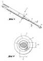
- FIG Reference number 1A drilling tool designed according to the invention is shown in its entirety in FIG Reference number 1 provided. It comprises a shaft 2, which essentially consists of a rear section 4 and a front section 3 is composed.
- the back one Section 4has a larger diameter than the front section 3.
- Im Transition area from the rear section 4 to the front sectionis one annular stop shoulder 6 is provided, which points away from the insertion end 5 and the Front section 3 of the shaft 2 faces.
- the thinner front section 3 and the rear section 4can, for example by friction welding, in one piece be connected. However, they are advantageously releasably connected to one another, by the end of the front section 3 in a bore 7 in the end face of the rear section 4 of the shaft 2 is inserted and not over there locking means shown is fixed.
- the locking meanscan be, for example Locking screw or similar locking mechanisms known per se.
- On the shafthas a front end opposite the insertion end Drill head 10, which will be described in more detail below.
- the thinner front section 3the shaft has an elliptical or lenticular geometry.
- the main axis a and the Secondary axis b running perpendicular to itare in a relationship to one another that can be from about 1.8: 1 to about 1.4: 1.
- This shaft geometrycan over extend the entire front section 3, it can also, as indicated in Fig. 1, only comprise a partial area of the front section 3. This results in that in FIG. 2 transition areas indicated in a circular or elliptical manner.
- Reference numeral 7is the bore in the front of the rear section designated.
- the end facealso forms the stop shoulder 6.
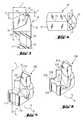
- a first embodiment of the drill headis overall with the Reference number 10 provided.
- the drill head 10is at the front end of the shaft 2 connected, for example welded or soldered. It has centering blades 11 and at least one secondary cutting edge 13 which extends from a centering tip 14 to the Side surfaces 15 of the drill head 10 extend and in their height relative to the Step back centering tip 14.
- the minor cutting edge 13extends eccentrically to the Axis of the shaft 2 and exceeds its circumference by a distance n.
- the circumference The outstanding proportion n of the extension of the minor cutting edge 13is approximately 10% up to 100% of their total extent I.
- the secondary cutting edge 13ends at the side wall 15 at a point whose distance s from the centering tip 14 is greater than that Distance t from the corresponding end point of the centering cutting edge 11.
- the Centering cutting edges 11 and the secondary cutting edge 13close at the centering tip Angle ⁇ from about 30 ° to about 120 °. While the drill head 10 on the Shank 2 can be attached to the underside of its supporting cutting edge Sections projecting freely above the shaft, it proves advantageous if the shaft 2 is on has a side extension 21 at its front end, which serves as support for the otherwise freely projecting section of the drill head 10 and the connecting surface between drill head 10 and shaft 2 enlarged. There are discharge grooves 16 on the shaft indicated that extend helically from the drill head 10 backwards.
- FIG. 4shows a top view of the drill head 10 according to FIG. 3 it can be seen that the drill head 10 has two centering cutting edges 11, 12 which start out extend from the centering tip 14 to the side surface 15 of the drill head 10.
- the two Centering blades 11, 12form an angle ⁇ at the centering tip 14 which is from can be about 60 ° to 180 °.
- the longer minor cutting edge 13runs in Extension of the bisector of the centering cutting edges 11, 12 included angle ⁇ . It closes with the adjacent centering cutting edges 11 or 12 each an obtuse angle.
- FIG. 5shows a second exemplary embodiment of the drill head 100 according to the invention trained drilling tool.
- the drill head 100has one Minor cutting edge 113, whose extension n, l is 100% outside the circumference of the Shaft of the drilling tool, not shown, runs.
- the circumference of the shaftthe radially closest area of the secondary cutting edge 113 is opposite the Centering tip 114 set back by at least 2.5 mm.
- the secondary cutting edge 113is assigned a drilling dust removal groove 117 which essentially axially extending in the side surface 115 of the drill head 100 is arranged to be in relation to the direction of rotation R of the secondary cutting edge 113 is downstream.
- the space in front of the secondary cutting edge 113 on the drill head 100already enables sufficient drilling dust to be transported. In the case of one The downstream is supported by an exceptionally high amount of drilling dust Bohrmehlabschreibnut 117 additionally the drilling dust transport.
- the further exemplary embodiment, designated overall by 200 in FIG. 6, of a The drill headlargely corresponds to the embodiment shown in FIG. 5.
- FIG. 7 and 8is a top view of the drill head 200 of the embodiment shown in FIG. 6.
- the reference numbers directed to the drill head 200correspond to those of Fig. 6.
- the reference symbol Bis a tubular Fastening element indicated, the one extending over its entire length has axial slot S.
- the fastener Bis on the drilling tool attached.
- Drill head 200extends beyond the front end of the fastener.
- the Fastener Bis drawn in two positions.
- the dashed linemeans Drawing the initial situation in which the slot S is open.
- the stripped Linesshow the fastener B in the set state, in which it is in the Receiving hole is radially clamped and in extreme cases the slot S on the block closed is.
- the drilling head 200 of the drilling toolis still in FIG Drilling position, the centering tip 214 extending the axis of the Drilling tool and the fastener B is arranged and the Centering blades 211, 212 prevent the drilling tool from drifting sideways when the secondary cutting edges 213, 218 are in degrading engagement with the subsurface.
- the one elliptical or lenticular shaftis indicated and with the Reference number 2 provided. It is immediately apparent that the minor cutting edges are a Drill a hole with a diameter that is larger than the diameter of the enveloping circle of the drilling head 200.
- the drilling toolIn the centered position, the drilling tool can not be pulled out of the fastener B set. To do this the drilling tool can only be moved laterally until the drilling head 200 moves with it its entire envelope circle within the inner diameter of the fastener B is as shown in FIG. 8. In this position, the drilling tool can be pulled out of the set fastening element B very easily.
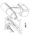
- FIG. 9an assembly unit is shown which allows, for example, a Insulation plate according to the direct assembly method according to the invention on a Fasten brick wall.
- the assembly unitincludes a tubular one Fastening element B, which with a mushroom-shaped load application means L for fixing Insulation plates is equipped, a drilling tool 1 according to the invention with a Stop shoulder 6 and a drill head 10 with an eccentric secondary cutting edge and a Hand tool T.
- the hand tool Tis, for example, a rotary drilling machine with axial stroke support. To prepare for the assembly process, first of all Drilling tool 1 with its insertion end in the tool holder of the hand tool T plugged in.
- the fastening element Bis then placed on the drilling tool 1 pushed on until the drill head 10 comes out of the front end of the tubular Fastener B protrudes.
- the arrows P1 and P2illustrate the in the representation Assembly of the drilling tool 1 and the fastening element B.
- Assembly unitconsisting of the hand tool T, the drilling tool 1 and the Fastener B is against the material of the insulation plate Pressed underground.
- the hand tool Tis actuated, the drilling tool 1 begins in Create a mounting hole underground. Once the front end of the tubular fastener B touches the surface, this follows, by axial Blows supported, the drill head 10 in the underground.
- the longitudinally slotted tubular fastener Bhas compared to the created bore hole and is therefore in the Driving in radially compressed.
- the hollow fastener Bforms for that Drilling tool 1 a radial guide. Prevent the centering cutters on the drill head that the drill head 10 drifts laterally when the at least one eccentric Minor cutting edge comes into engagement with the subsurface.
- the axially driven tubular fastener Bpulls the load application means L into the material of the Insulation plate until the large-area head part of the load application means L, preferably is flush with the surface of the plate.
Landscapes
- Engineering & Computer Science (AREA)
- Mechanical Engineering (AREA)
- Mining & Mineral Resources (AREA)
- Processing Of Stones Or Stones Resemblance Materials (AREA)
- Drilling Tools (AREA)
- Surgical Instruments (AREA)
- Saccharide Compounds (AREA)
- Steroid Compounds (AREA)
- Perforating, Stamping-Out Or Severing By Means Other Than Cutting (AREA)
Abstract
Description
Translated fromGermanDie Erfindung betrifft ein Bohrwerkzeug mit einem länglichen Schaft, dessen eines,rückwärtiges Ende als Einsteckende ausgebildet ist und der am gegenüberliegendenVorderende mit Bohrschneiden ausgestattet ist, gemäss dem Oberbegriff desPatentanspruchs 1.The invention relates to a drilling tool with an elongated shaft, one of which,rear end is designed as an insertion end and the oppositeFront end is equipped with cutting edges, according to the preamble of
Für die Erstellung von Befestigungen in unterschiedlich festen Untergründen werdenverschiedene Verfahren eingesetzt. Am gebräuchlichsten sind sequentielle Verfahrenund die Direkt-Montagetechnik. Sequentielle Befestigungsverfahren sind für alle Artenvon Untergründen geeignet. Je nach Art des Untergrunds und der zu erzielendenBefestigungswerte kommen auch unterschiedliche Arten von Befestigungselementenzum Einsatz. Bei dem sequentiellen Verfahren wird zunächst mit einer Bohreinrichtungim Untergrund eine Aufnahmebohrung erstellt. Die Bohreinrichtung besteht dabei auseinem Metall-, Gesteins- oder auch Holzbohrer, der von einem Handgerät mitmotorischem Drehantrieb und gegebenenfalls axialer Schlagunterstützung angetriebenwird. Nach der Erstellung der Aufnahmebohrung wird ein Befestigungselement -üblicherweise ein Dübel - in die Aufnahmebohrung eingesetzt und in den meisten Fällendurch Eindrehen einer Schraube oder durch Einschlagen eines Dorns aufgespreizt undin der Aufnahmebohrung verankert. Als mechanische Befestigungselemente könnenauch Kunststoff- oder Metalldorne mit einem Kopf eingesetzt werden, die mit einemHammer in die vorgebohrte Aufnahmebohrung eingetrieben werden. DerHaltemechanismus beruht meist auf Reibschluss, in Hohllochziegeln manchmal auch aufFormschluss.For the creation of fastenings in different solid substratesdifferent procedures used. Sequential methods are the most commonand direct assembly technology. Sequential fastening procedures are common to all typessuitable for substrates. Depending on the type of surface and the one to be achievedFastening values also come in different types of fastenersfor use. In the sequential method, a drilling device is used firstcreated a mounting hole in the underground. The drilling device consists ofa metal, stone or wood drill that can be used with a handheld devicemotor-driven rotary drive and, if necessary, axial impact supportbecomes. After creating the location hole, a fastener -usually a dowel - inserted in the location hole and in most casesspread by screwing in a screw or by driving in a mandrel andanchored in the mounting hole. Can as mechanical fastenersalso plastic or metal mandrels can be used with a head, with aHammer be driven into the pre-drilled mounting hole. Of theThe holding mechanism is mostly based on friction, sometimes also in hollow perforated bricksPositive locking.
Bei der Direkt-Montagetechnik wird ein spezielles Befestigungselement mit Hilfe einespulverkraftbetriebenen Setzgerätes direkt in den Untergrund eingetrieben. Bei dieserBefestigungsmethode entfällt das separate Erstellen einer Aufnahmebohrung für dasBefestigungselement. Die Direkt-Montagetechnik ist schnell und führt zu Befestigungenmit hohen Haltewerten. Allerdings ist die bekannte Direkt-Montagetechnik nur für mehr oder weniger duktile Untergründe, wie beispielsweise Stahl, Kalksandstein, Beton oderggf. Holz, geeignet.In the case of direct assembly technology, a special fastening element is used with the help of apowder-powered setting tool driven directly into the ground. At thisFastening method eliminates the separate creation of a mounting hole for theFastener. The direct assembly technology is fast and leads to fasteningswith high holding values. However, the well-known direct assembly technology is only for moreor less ductile substrates such as steel, sand-lime brick, concrete orif necessary, wood, suitable.
Weniger feste oder spröde Untergründe, wie beispielsweise Ziegelmauerwerk, werdenbei der bekannten Direkt-Montagetechnik mittels pulverkraftbetriebenen Setzgerätensehr stark beansprucht und oft sogar beschädigt und führen zu keinen zuverlässigenBefestigungen. Daher wird für Verankerungen in diesen Untergründen im wesentlichennur das sequentielle Befestigungsverfahren eingesetzt. Dieses schont den Untergrundund führt zu zuverlässigen Befestigungen mit den gewünschten Haltewerten. Allerdingsmuss dafür ein deutlich grösserer Zeitaufwand je Befestigungspunkt in Kauf genommenwerden. Ausserdem sind meist separate Geräte für die Erstellung derAufnahmebohrungen und für die Verankerung der Befestigungselemente in denAufnahmebohrungen erforderlich, beispielsweise ein Bohrgerät mit Bohreinrichtung zumBohren der Aufnahmebohrung und ein Schraubgerät zum Eindrehen einerBefestigungsschraube in einen Dübel, wobei der Dübel durch Aufspreizen verankertwird.Less solid or brittle surfaces, such as brick masonryin the known direct assembly technology using powder-operated setting toolsvery stressed and often even damaged and do not lead to any reliableFortifications. Therefore, it is essential for anchoring in these substratesonly the sequential fastening method used. This protects the undergroundand leads to reliable fastenings with the desired retention values. Indeeda much larger amount of time per attachment point has to be acceptedwill. In addition, there are usually separate devices for creating theMounting holes and for anchoring the fasteners in theLocation holes required, for example a drill with drilling device forDrill the mounting hole and a screwdriver to screw oneFixing screw in a dowel, the dowel being anchored by spreadingbecomes.
Aufgabe der vorliegenden Erfindung ist es daher, die Voraussetzungen zu schaffen,damit auch in spröden Untergründen, beispielsweise in Ziegelmauerwerk, schnell undzuverlässig ein Befestigungselement verankert werden kann. Insbesondere soll durchdie Erfindung ein Bohrwerkzeug geschaffen werden, welches in Verbindung mit einemneuartigen Befestigungselement und einer neuartigen Befestigungstechnik zum Einsatzkommt. Dabei soll auf die sequentielle Abfolge des Erstellens einer Aufnahmebohrungund des nachfolgenden Einsetzens eines Befestigungselements in dieAufnahmebohrung und schliesslich des Verspreizens des Befestigungselementsverzichtet werden können. Die Notwendigkeit, mehrere verschiedene Geräte für dieErstellung der Aufnahmebohrung und für die nachfolgende Verankerung desBefestigungselements mitzuführen, soll entfallen können. Der Untergrund soll geschontwerden und es sollen Befestigungen mit den geforderten Haltewerten erzielt werdenkönnen.The object of the present invention is therefore to create the conditionsthus also in brittle surfaces, for example in brick masonry, quickly anda fastener can be reliably anchored. In particular, bythe invention a drilling tool can be created, which in connection with anovel fastening element and a new fastening technology for useis coming. The aim is to focus on the sequential sequence of creating a location holeand the subsequent insertion of a fastener into theLocation hole and finally the expansion of the fastenercan be dispensed with. The need to have several different devices for thatCreation of the mounting hole and for the subsequent anchoring of theCarrying fastener should be omitted. The surface should be protectedand fastenings with the required retention values should be achievedcan.
Die Lösung der vorstehenden Aufgaben besteht in einem Bohrwerkzeug, welches die imkennzeichnenden Abschnitt des Patentanspruchs 1 angeführten Merkmale aufweist.Insbesondere wird durch die Erfindung ein Bohrwerkzeug mit einem länglichen Schaftgeschaffen, dessen eines, rückwärtiges Ende als Einsteckende ausgebildet ist und deram gegenüberliegenden Vorderende einen mit Bohrschneiden ausgestatteten Bohrkopf aufweist. Am Schaft ist eine vorzugsweise ringförmige Schulter angeordnet, die inRichtung dem Bohrkopf zugewandt ist. Der Bohrkopf weist Zentrierschneiden auf, dievon einer im wesentlichen in Verlängerung der Schaftachse angeordneten, vorlaufendenZentrierspitze zum Umfang des Bohrkopfs hin zurücktreten. Neben denZentrierschneiden ist am Bohrkopf wenigstens eine Nebenschneide vorgesehen, derensenkrecht zur Schaftachse verlaufende Erstreckung den Umfang des Schafts überragt,wobei der den Schaftumfang überragende Anteil der Erstreckung der Nebenschneideetwa 10 % bis 100 % ihrer Gesamterstreckung ausmacht.The solution to the above problems consists in a drilling tool, which incharacterizing section of
Durch das erfindungsgemässe Bohrwerkzeug sind die Voraussetzungen dafürgeschaffen, ein neuartiges Befestigungselement, das einen rohrförmig ausgebildeten,metallischen Schaft mit einer axialen Durchgangsbohrung und einem sich über diegesamte Schaftlänge erstreckenden, axialen Schlitz im Mantel des Schafts, sowieLastangriffsmittel am der Setzrichtung abgewandten rückwärtigen Endabschnitt desSchafts aufweist, in einem Direktbefestigungsverfahren im Untergrund zu verankern.Aufgrund der erfindungsgemässen Konstruktion des Bohrwerkzeugs wird in einemArbeitsgang mit dem Bohrwerkzeug eine Aufnahmebohrung erstellt und wird dasBefestigungselement synchron durch axiale Schläge in den Untergrund eingetrieben.Der Bohrkopf des Bohrwerkzeugs ist derart gestaltet, dass das Befestigungselement aufden Schaft aufgeschoben werden kann, bis sein Kragen an der Anschlagschulteransteht. Der Bohrkopf überragt dabei das vordere Ende des Befestigungselements. DieAnschlagschulter dient der Übertragung von axialen Schlägen auf das Befestigungselement,durch die dieses synchron mit der Erstellung der Aufnahmebohrung in denUntergrund eingetrieben wird. Im gesetzten Zustand des Befestigungselements, mit imExtremfall vollständig geschlossenem axialen Schlitz, kann das Bohrwerkzeug wiederaus dem Befestigungselement herausgezogen werden, da der Hüllkreis des Bohrkopfeskleiner ist als der Innendurchmesser des auf Block geschlossenen rohrförmigenBefestigungselements. Die Zentrierspitze stützt das Bohrwerkzeug gegen ein Abdriftenaus der Achsmitte, wenn die wenigstens eine asymmetrisch angeordneteNebenschneide in Eingriff mit dem Untergrund ist.The drilling tool according to the invention provides the prerequisites for thiscreated a new type of fastener that has a tubular,Metallic shaft with an axial through hole and one over theentire shaft length extending, axial slot in the jacket of the shaft, as wellLoad application means on the rear end section of theHas to be anchored in the underground in a direct fastening process.Due to the construction of the drilling tool according to the invention, in oneWorking step with the drilling tool creates a location hole and willFastener driven into the ground synchronously by axial blows.The drill head of the drilling tool is designed such that the fastening element is onthe shaft can be pushed on until its collar on the shoulderpending. The drill head projects beyond the front end of the fastening element. TheStop shoulder is used to transmit axial impacts to the fastener,through which this is synchronized with the creation of the location hole in theIs driven underground. In the set state of the fastener, with inIn the extreme case of a completely closed axial slot, the drilling tool can be used againbe pulled out of the fastener as the envelope circle of the drill headis smaller than the inside diameter of the tubular closed on blockFastener. The centering tip supports the drilling tool against driftingfrom the center of the axle if the at least one asymmetrically arrangedMinor cutting edge is in engagement with the subsurface.
Es erweist sich von Vorteil, wenn zwei Zentrierschneiden vorgesehen sind, diemiteinander einen Winkel von etwa 60° bis etwa 180° einschliessen, und eine Nebenschneideangeordnet ist, die ausgehend von der Zentrierspitze zur ausserhalb desSchaftumfangs verlaufenden Seitenwandung des Bohrkopfes hin zurücktritt, wobei in deraxialen Draufsicht des Bohrkopfes die Nebenschneide mit der benachbarten Zentrierschneide jeweils einen stumpfen Winkel einschliesst. Bei der gewählten Geometriehalten sich im Betrieb die Kräfte an den Schneidkanten die Waage und verbessern dieAbstützung des Bohrwerkzeugs in der Aufnahmebohrung. Aus Gründen einersymmetrischen Kraftverteilung ist es zweckmässig, wenn sich die Nebenschneideparallel, vorzugsweise in Verlängerung, zur Winkelhalbierenden der Zentrierschneidenerstreckt.It proves advantageous if two centering cutting edges are provided, whichform an angle of about 60 ° to about 180 ° with each other and a minor cutting edgeis arranged, starting from the centering point to outside of theShaft circumferential side wall of the drill head back, being in theaxial plan view of the drill head, the minor cutting edge with the adjacent centering cutting edgeeach includes an obtuse angle. With the chosen geometrythe forces on the cutting edges keep the balance and improve theSupport of the drilling tool in the location hole. For the sake of onesymmetrical force distribution it is useful if the minor cutting edgeparallel, preferably in extension, to bisect the centering edgesextends.
Indem das ausserhalb des Schaftumfangs liegende Ende der Nebenschneide einengrösseren Abstand von der Zentrierspitze aufweist als die im Bereich des Schaftumfangsliegenden Enden der Zentrierschneiden wird die Asymmetrie des Bohrkopfs noch weiterbetont. Die Nebenschneide ist länger als die Zentrierschneiden und besorgt denhauptsächlichen Materialabtrag.By the end of the minor cutting edge lying outside the shaft circumferencehas a greater distance from the centering tip than that in the region of the shaft circumferenceThe asymmetry of the drill head is further increased by the lying ends of the centering cutting edgesstressed. The minor cutting edge is longer than the centering cutting edges and provides themain material removal.
Für den Ausgleich der Kräfte an den Schneidkanten der Zentrierschneiden und derNebenschneide erweist sich eine Anordung von Vorteil, bei der in Seitenansicht dieNebenschneide und die Zentrierschneide an der Zentrierspitze einen Winkel von etwa30° bis etwa 120° einschliessen.For balancing the forces on the cutting edges of the centering blades and theA secondary edge proves to be an arrangement in which the side viewSecondary cutting edge and the centering cutting edge at the centering tip an angle of approximatelyInclude 30 ° to about 120 °.
In einer sehr zweckmässigen, alternativen Variante des Bohrwerkzeugs ist der demSchaftumfang radial am nächsten liegende Bereich der Nebenschneide gegenüber derZentrierspitze um wenigstens 2,5 mm zurückgesetzt. In diesem Fall erstreckt sich dieNebenschneide nicht bis zur Zentrierspitze, sondern sie ist gegenüber dieserzurückversetzt und seitlich des Schaftumfangs angeordnet. Die Zentrierschneiden mitder Zentrierspitze besitzen eine sehr ausgeprägte Zentrierbohrerfunktion. Sie dienenallein der Abstützung des Bohrwerkzeugs gegen ein seitliches Abdriften aus derAchsmitte, wenn die asymmetrisch angeordnete Nebenschneide in Eingriff mit demUntergrund ist. Die Nebenschneide bohrt schlagend und schabend um dieZentrierbohrung herum eine Aufnahmebohrung mit dem gewünschten Durchmesser, dergrösser ist als der Hüllkreisdurchmesser des Bohrkopfs und derart bemessen ist, dassdas rohrförmige Befestigungselement in der Aufnahmebohrung verspannt wird. Dieresultierende Haltekraft des Befestigungselements ist ein Ergebnis der Anpresskraft andie Bohrungswandung infolge des Verspannens und des Haftreibungsbeiwertes.In a very useful, alternative variant of the drilling tool, this is theRadially closest shaft circumference of the minor cutting edge opposite theCentering point set back by at least 2.5 mm. In this case, theSecondary cutting edge not up to the centering point, but it is opposite thisset back and arranged to the side of the shaft circumference. The centering edges withthe center point have a very distinctive center drill function. You serveonly the support of the drilling tool against lateral drifting out of theAxis center when the asymmetrically arranged secondary cutting edge engages with theIs underground. The minor cutting edge drills and shakes around theCenter hole around a location hole with the desired diameter, theis larger than the envelope diameter of the drill head and is dimensioned such thatthe tubular fastening element is clamped in the receiving bore. Theresulting holding force of the fastener is a result of the contact pressurethe bore wall due to the tension and the coefficient of static friction.
Der Bohrkopf kann mit einer oder mit mehreren Nebenschneiden ausgestattet sein. FürAnwendungen auch in härteren Untergründen, beispielsweise in Betonuntergründen mit harten Zuschlagsstoffen, erweisen sich zwei Nebenschneiden von Vorteil, diemiteinander einen Winkel von 30° bis 50°, vorzugsweise etwa 40° einschliessen.The drill head can be equipped with one or more secondary cutting edges. ForApplications also in harder substrates, for example in concrete substrateshard aggregates, two minor cutting edges prove to be of advantageform an angle of 30 ° to 50 ° with one another, preferably about 40 °.
Für die Unterstützung des Bohrmehltransports ist jeder Nebenschneide eineBohrmehlabfuhrnut zugeordnet ist, die bezogen auf die Drehrichtung des Bohrkopfs derNebenschneide nachgelagert ist und axial in der Seitenwandung des Bohrkopfs verläuft.Each secondary cutting edge is one to support the drilling dust transportBohrmehlabfuhrnut is assigned, which is related to the direction of rotation of the drill headSecondary cutting edge is located downstream and runs axially in the side wall of the drill head.
Um den Bohrmehlabtransport weiter zu verbessern, ist der Schaft ellipsen- bzw.linsenförmig ausgebildet. Durch die elliptische bzw. linsenförmige Gestalt des Schaftsdes Bohrwerkzeugs wird das abgebaute Bohrklein bzw. Bohrmehl radial nach aussenverdrängt und durch die entstehende Verdrängungswirkung nach rückwärts transportiert.Abfuhrnuten, die im Schaft eingeprägt sein können, unterstützen den Bohrmehltransportnoch weiter. Die elliptische bzw. linsenförmige Schaftgeometrie verleiht demBohrwerkzeug eine hohe Drehmomentstabilität und gewährleistet zugleich eineausreichende Biegeweichheit, um das Bohrwerkzeug auch bei schräg gesetztenBefestigungselementen, bei denen manchmal eine leichte Biegung in Achsrichtungauftreten kann, problemlos herausziehen zu können. Besonders gute Verhältnissebezüglich der Drehmomentstabilität einerseits und der Biegeweichheit des Schaftsandererseits ergeben sich bei Verhältnissen des grössten Durchmessers des Schaftsund des senkrecht dazu verlaufenden kleinsten Durchmessers des Schafts, die von etwa1,8 : 1 bis etwa 1,4 : 1 betragen.To further improve the removal of drilling dust, the shaft is elliptical orlenticular. Due to the elliptical or lenticular shape of the shaftof the drilling tool, the mined cuttings or drilling dust is removed radially outwardsdisplaced and transported backwards by the resulting displacement effect.Removal grooves, which can be embossed in the shaft, support the drilling dust transportfurther. The elliptical or lenticular shaft geometry gives thisDrilling tool high torque stability and at the same time ensures onesufficient flexibility to hold the drilling tool even when placed at an angleFasteners, which sometimes have a slight bend in the axial directioncan occur to be able to pull out easily. Particularly good conditionswith regard to the torque stability on the one hand and the flexibility of the shafton the other hand, there are ratios of the largest diameter of the shaftand the smallest diameter of the shaft running perpendicular to it, that of about1.8: 1 to about 1.4: 1.
Der Schaft ist zweckmässigerweise zweiteilig ausgebildet und umfasst einendurchmessergrösseren rückwärtigen Abschnitt mit dem Einsteckende und einendünneren vorderen Schaftabschnitt. Der Bohrkopf ist am freien Vorderende des vorderenSchaftabschnitts befestigt, der vorzugsweise eine elliptische bzw. linsenförmigeGeometrie aufweist. Der vordere Schaftabschnitt ist lösbar mit dem rückwärtigenAbschnitt verbunden. Beispielsweise mündet an der dem Einsteckendegegenüberliegenden Stirnwand des rückwärtigen Abschnitts eine Einsteckbohrung, in dieder dünnere vordere Schaftabschnitt einsteckbar ist. Verriegelungselemente verhinderndas Herausfallen des eingesteckten vorderen Schaftabschnitts. Die dem dünnerenSchaftabschnitt zugewandte Stirnwand des rückwärtigen Abschnitts bildet zugleich dieAnschlagschulter für ein aufgeschobenes Befestigungselement, damit vom Handgeräterzeugte axiale Schläge auf das Befestigungselement übertragbar sind. Durch dielösbare Halterung des vorderen, dünneren Schaftabschnitts muss im Fall einesübermässigen Verschleisses des Bohrkopfs nicht das gesamte Bohrwerkzeug ersetzt werden. Es genügt, den vorderen Schaftabschnitt mit dem Bohrkopf auszutauschen.Analoges gilt für den Fall, dass der mit dem Einsteckende versehene rückwärtigeAbschnitt ersetzt werden muss. Auch in diesem Fall kann der noch unversehrte Teil desBohrwerkzeugs weiterverwendet werden.The shaft is expediently formed in two parts and comprises onelarger diameter rear section with the insertion end and onethinner front shaft section. The drill head is at the free front end of the frontSecured shaft section, which is preferably an elliptical or lenticularHas geometry. The front shaft section is detachable from the rearSection connected. For example, the end of the insertion endsopposite end wall of the rear section an insertion hole in thethe thinner front shaft section can be inserted. Prevent locking elementsfalling out of the inserted front shaft section. The thinner oneEnd wall of the rear section facing the shaft section also forms theStop shoulder for a pushed fastener, so from the handheld devicegenerated axial impacts are transferable to the fastener. Through theRemovable mounting of the front, thinner shaft section must be in the case of aexcessive wear of the drill head does not replace the entire drilling toolwill. It is sufficient to replace the front shank section with the drill head.The same applies in the event that the rear end provided with the insertion endSection needs to be replaced. In this case too, the still intact part of theDrilling tools continue to be used.
Als Material für den Bohrkopf kommt vorzugsweise Hartmetall zum Einsatz. Dadurchweist das Bohrwerkzeug eine hohe Verschleissfestigkeit auf und es besitzt eineausreichende Härte, um auch in festen Untergründen Aufnahmebohrungen erstellen zukönnen. Die Befestigung des Bohrkopfs am Schaft erfolgt auf an sich bekannte Weise,beispielsweise durch Schweissen oder Löten.Hard metal is preferably used as the material for the drill head. Therebythe drilling tool has a high wear resistance and it has onesufficient hardness to create locating holes even in solid surfacescan. The drill head is attached to the shaft in a manner known per se,for example by welding or soldering.
Im folgenden wird die Erfindung anhand von Ausführungsbeispielen unter Bezugnahmeauf die schematischen Zeichnungen näher erläutert. Es zeigen:
- Fig. 1
- eine perspektivische Darstellung eines erfindungsgemässen Bohrwerkzeugs;
- Fig. 2
- einen Schnitt durch den Schaft des Bohrwerkzeugs gemäss Schnittlinie II-II inFig. 1;
- Fig. 3
- eine Seitenansicht eines ersten Ausführungsbeispiels eines Bohrkopfs;
- Fig. 4
- eine Draufsicht des Bohrkopfs gemäss Fig. 3;
- Fig. 5
- eine perspektivische Darstellung eines zweiten Ausführungsbeispiels desBohrkopfs;
- Fig. 6
- eine perspektivische Darstellung eines dritten Ausführungsbeispiels desBohrkopfs;
- Fig. 7 und Fig. 8
- zwei Draufsichten des Bohrkopfs gemäss Fig. 4 mit angedeutetemBefestigungselement; und
- Fig. 9
- eine Darstellung einer Montageeinheit zur Direktbefestigung einesBefestigungselements mit Hilfe eines erfindungsgemässen Bohrwerkzeugs.
- Fig. 1
- a perspective view of a drilling tool according to the invention;
- Fig. 2
- a section through the shaft of the drilling tool according to section line II-II in Fig. 1;
- Fig. 3
- a side view of a first embodiment of a drill head;
- Fig. 4
- a plan view of the drill head according to FIG. 3;
- Fig. 5
- a perspective view of a second embodiment of the drill head;
- Fig. 6
- a perspective view of a third embodiment of the drill head;
- 7 and 8
- two top views of the drill head according to FIG. 4 with indicated fastening element; and
- Fig. 9
- a representation of an assembly unit for direct attachment of a fastener using an inventive drilling tool.
Ein erfindungsgemäss ausgebildetes Bohrwerkzeug ist in Fig. 1 gesamthaft mit demBezugszeichen 1 versehen. Es umfasst einen Schaft 2, der sich im wesentlichen auseinem rückwärtigen Abschnitt 4 und einem Vorderabschnitt 3 zusammensetzt. Der rückwärtigeAbschnitt 4 weist einen grösseren Durchmesser auf als der Vorderabschnitt 3. ImÜbergangsbereich vom rückwärtigen Abschnitt 4 zum Vorderabschnitt ist eineringförmige Anschlagschulter 6 vorgesehen, die vom Einsteckende 5 wegweist und demVorderabschnitt 3 des Schafts 2 zugewandt ist. Der dünnere Vorderabschnitt 3 und derrückwärtige Abschnitt 4 können, beispielsweise durch Reibschweissen, einstückigmiteinander verbunden sein. Mit Vorteil sind sie aber lösbar miteinander verbunden,indem das Ende des Vorderabschnitts 3 in eine Bohrung 7 in der Stirnfläche desrückwärtigen Abschnitts 4 des Schafts 2 eingesetzt ist und dort über nicht näherdargestellte Arretiermittel fixiert ist. Die Arretiermittel können beispielsweise eineArretierschraube oder ähnliche an sich bekannte Verriegelungsmechanismen sein. Anseinem dem Einsteckende gegenüberliegenden Vorderende weist der Schaft einenBohrkopf 10 auf, der in der Folge noch näher beschrieben wird.A drilling tool designed according to the invention is shown in its entirety in
Wie aus der Schnittdarstellung der Fig. 2 ersichtlich, weist der dünnere Vorderabschnitt 3des Schafts eine elliptische bzw. linsenförmige Geometrie auf. Die Hauptachse a und diesenkrecht dazu verlaufende Nebenachse b stehen in einem Verhältnis zueinander, dasvon etwa 1,8 : 1 bis etwa 1,4 : 1 betragen kann. Diese Schaftgeometrie kann sich überden gesamten Vorderabschnitt 3 erstrecken, sie kann auch, wie in Fig. 1 angedeutet, nureinen Teilbereich des Vorderabschnitts 3 umfassen. Dadurch ergeben sich die in Fig. 2kreisförmig bzw. ellipsenförmig angedeuteten Übergangsbereiche. Mit demBezugszeichen 7 ist die Bohrung in der Stirnseite des rückwärtigen Abschnittsbezeichnet. Die Stirnseite bildet zugleich die Anschlagschulter 6.As can be seen from the sectional view in FIG. 2, the
In Fig. 3 ist ein erstes Ausführungsbeispiel des Bohrkopfs gesamthaft mit demBezugszeichen 10 versehen. Der Bohrkopf 10 ist mit dem Vorderende des Schafts 2verbunden, beispielsweise angeschweisst oder angelötet. Er weist Zentrierschneiden 11und wenigstens eine Nebenschneide 13 auf, die sich von einer Zentrierspitze 14 zu denSeitenflächen 15 des Bohrkopfs 10 erstrecken und dabei in ihrer Höhe gegenüber derZentrierspitze 14 zurücktreten. Die Nebenschneide 13 erstreckt sich exzentrisch zu derAchse des Schafts 2 und überragt dessen Umfang um eine Strecke n. Der den Umfangüberragende Anteil n der Erstreckung der Nebenschneide 13 beträgt etwa 10 % bis zu100 % ihrer Gesamterstreckung I. Die Nebenschneide 13 endet an der Seitenwandung15 in einem Punkt, dessen Abstand s von der Zentrierspitze 14 grösser ist als der Abstand t des korrespondierenden Endpunktes der Zentrierschneide 11. DieZentrierschneiden 11 und die Nebenschneide 13 schliessen an der Zentrierspitze einenWinkel α von etwa 30° bis etwa 120° ein. Während der Bohrkopf 10 derart auf demSchaft 2 befestigt sein kann, dass die Unterseite seines die Nebenschneide tragendenAbschnitts den Schaft frei überragt, erweist es sich von Vorteil, wenn der Schaft 2 anseinem Vorderende eine seitliche Erweiterung 21 aufweist, die als Unterstützung für densonst frei überstehenden Abschnitt des Bohrkopfs 10 dient und die Verbindungsflächezwischen Bohrkopf 10 und Schaft 2 vergrössert. Am Schaft sind Abfuhrnuten 16angedeutet, die sich vom Bohrkopf 10 wendelförmig nach rückwärts erstrecken.In Fig. 3, a first embodiment of the drill head is overall with the
Fig. 4 zeigt eine Draufsicht auf den Bohrkopf 10 gemäss Fig. 3. Insbesondere istersichtlich, dass der Bohrkopf 10 zwei Zentrierschneiden 11, 12 aufweist, die ausgehendvon der Zentrierspitze 14 zur Seitenfläche 15 des Bohrkopfs 10 verlaufen. Die beidenZentrierschneiden 11, 12, schliessen an der Zentrierspitze 14 einen Winkel γ ein, der vonetwa 60° bis 180° betragen kann. Die längere Nebenschneide 13 verläuft inVerlängerung der der Winkelhalbierenden des von den Zentrierschneiden 11, 12eingeschlossenen Winkels γ. Sie schliesst mit den benachbarten Zentrierschneiden 11bzw. 12 jeweils einen stumpfen Winkel ein.FIG. 4 shows a top view of the
Fig. 5 zeigt ein zweites Ausführungsbeispiel des Bohrkopfs 100 eines erfindungsgemässausgebildeten Bohrwerkzeugs. Bei dem dargestellten Ausführungsbeispiel sind dieZentrierschneiden mit 111 bzw. 112 bezeichnet. Der Bohrkopf 100 weist eineNebenschneide 113 auf, deren Erstreckung n, l zu 100 % ausserhalb des Umfangs desnicht näher dargestellten Schafts des Bohrwerkzeugs verläuft. Der dem Schaftumfangradial am nächsten liegende Bereich der Nebenschneide 113 ist gegenüber derZentrierspitze 114 um wenigstens 2,5 mm zurückgesetzt. Wie aus der Darstellungersichtlich, ist der Nebenschneide 113 eine Bohrmehlabfuhrnut 117 zugeordnet, diederart im wesentlichen axial verlaufend in der Seitenfläche 115 des Bohrkopfs 100angeordnet ist, dass sie in Bezug auf die Drehrichtung R der Nebenschneide 113nachgelagert ist. Der der Nebenschneide 113 vorgelagerte Freiraum am Bohrkopf 100ermöglicht bereits einen ausreichenden Bohrmehltransport. Im Fall einesaussergewöhnlich hohen Bohrmehlanfalls unterstützt die nachgelagerteBohrmehlabfuhrnut 117 den Bohrmehltransport noch zusätzlich.5 shows a second exemplary embodiment of the
Das in Fig. 6 gesamthaft mit 200 bezeichnete weitere Ausführungsbeispiel einesBohrkopfs entspricht weitgehend dem in Fig. 5 dargestellten Ausführungsbeispiel.The further exemplary embodiment, designated overall by 200 in FIG. 6, of aThe drill head largely corresponds to the embodiment shown in FIG. 5.
Einander entsprechende Merkmale weisen demgemäss die gleichen beiden Endziffernauf, denen zur Unterscheidung der Ausführungsbeispiele eine ,2" vorangestellt ist. Derwesentliche Unterschied der beiden Ausführungsbeispiele besteht in der Anordnung vonzwei Nebenschneiden 213, 218, die miteinander einen Winkel β einschliessen, der vonetwa 30° bis etwa 50°, vorzugsweise etwa 40°, betragen kann. Den Nebenschneiden213, 218 sind bezogen auf die Drehrichtung des Bohrkopfs 200 jeweilsBohrmehlabfuhrnuten 217, 219 nachgelagert, die den Bohrmehltransport noch weiterverbessern.Corresponding features accordingly have the same two final digitswhich are preceded by a "2" to distinguish the exemplary embodimentsThe essential difference between the two exemplary embodiments is the arrangement oftwo
In Fig. 7 und Fig. 8 ist eine Draufsicht auf den Bohrkopf 200 des Ausführungsbeispielsgemäss Fig. 6 dargestellt. Die auf den Bohrkopf 200 gerichteten Bezugszeichenentsprechen denen aus Fig. 6. Mit dem Bezugszeichen B ist ein rohrförmigesBefestigungselement angedeutet, das einen über seine gesamte Länge verlaufendenaxialen Schlitz S aufweist. Das Befestigungselement B ist auf das Bohrwerkzeugaufgesteckt. Der Bohrkopf 200 überragt das Vorderende des Befestigungselements. DasBefestigungselement B ist in zwei Stellungen gezeichnet. Dabei bedeutet die strichlierteZeichnung die Ausgangssituation, in der der Schlitz S geöffnet ist. Die ausgezogenenLinien zeigen das Befestigungselement B im gesetzten Zustand, in dem es in derAufnahmebohrung radial verspannt ist und im Extremfall der Schlitz S auf Blockgeschlossen ist. Der Bohrkopf 200 des Bohrwerkzeugs befindet sich noch inBohrstellung, wobei die Zentrierspitze 214 in Verlängerung der Achse desBohrwerkzeugs und des Befestigungselements B angeordnet ist und dieZentrierschneiden 211, 212 verhindern, dass das Bohrwerkzeug seitlich abdriftet, wenndie Nebenschneiden 213, 218 in abbauendem Eingriff mit dem Untergrund sind. Der eineellipsen- bzw. linsenförmige Geometrie aufweisende Schaft ist angedeutet und mit demBezugszeichen 2 versehen. Es ist unmittelbar ersichtlich, dass die Nebenschneiden eineAufnahmebohrung mit einem Durchmesser erstellen, der grösser ist als der Durchmesserdes Hüllkreises des Bohrkopfs 200. In der zentrierten Stellung kann das Bohrwerkzeugnicht aus dem gesetzten Befestigungselement B herausgezogen werden. Dazu mussdas Bohrwerkzeug erst seitlich verschoben werden, bis sich der Bohrkopf 200 mitseinem gesamten Hüllkreis innerhalb des Innendurchmessers des BefestigungselementsB befindet, wie in Fig. 8 dargestellt. In dieser Position kann das Bohrwerkzeugsehr einfach aus dem gesetzten Befestigungselement B herausgezogen werden.7 and 8 is a top view of the
In Fig. 9 ist eine Montageeinheit dargestellt, die es erlaubt, beispielsweise eineIsolationsplatte nach dem erfindungsgemässen Direkt-Montageverfahren an einer Ziegelmauerwand zu befestigen. Die Montageeinheit umfasst ein rohrförmigesBefestigungselement B, das mit einem pilzförmigen Lastangriffsmittel L zur Fixierung vonIsolationsplatten ausgestattet ist, ein erfindungsgemässes Bohrwerkzeug 1 mit einerAnschlagschulter 6 und einem Bohrkopf 10 mit exzentrischer Nebenschneide und einHandgerät T. Bei dem Handgerät T handelt es sich beispielsweise um ein Drehbohrgerätmit Axialschlagunterstützung. Zur Vorbereitung des Montagevorgangs wird zunächst dasBohrwerkzeug 1 mit seinem Einsteckende in die Werkzeugaufnahme des Handgeräts Teingesteckt. Danach wird das Befestigungselement B auf das Bohrwerkzeug 1aufgeschoben, bis der Bohrkopf 10 aus dem Vorderende des rohrförmigenBefestigungselements B ragt. Die Pfeile P1 und P2 verdeutlichen in der Darstellung dieMontage des Bohrwerkzeugs 1 und des Befestigungselements B. Die derart vorbereiteteMontageeinheit, bestehend aus dem Handgerät T, dem Bohrwerkzeug 1 und demBefestigungselement B wird durch das Material der Isolationsplatte gegen denUntergrund gepresst. Bei Betätigung des Handgeräts T beginnt das Bohrwerkzeug 1 imUntergrund eine Aufnahmebohrung zu erstellen. Sobald das Vorderende desrohrförmigen Befestigungselements B den Untergrund berührt, folgt dieses, durch axialeSchläge unterstützt, dem Bohrkopf 10 in den Untergrund. Dabei werden die vomHandgerät T erzeugten axialen Schläge über die Anschlagschulter 6 auf das rückwärtigeEnde des rohrförmigen Befestigungselements B übertragen, das sich im dargestelltenBeispiel innerhalb des pilzförmigen Lastangriffsmittels L abstützt. Auf diese Weise wirdkontinuierlich gebohrt und gleichzeitig das Befestigungselement B schlagend in denUntergrund eingetrieben. Das längsgeschlitzte rohrförmige Befestigungselement B weistgegenüber der erstellten Aufnahmebohrung ein Übermass auf und wird daher beimEintreiben radial zusammengepresst. Das hohle Befestigungselement B bildet für dasBohrwerkzeug 1 eine radiale Führung. Die Zentrierschneiden am Bohrkopf verhindern,dass der Bohrkopf 10 seitlich abdriftet, wenn die wenigstens eine exzentrischeNebenschneide in Eingriff mit dem Untergrund kommt. Das axial eingetriebenerohrförmige Befestigungselement B zieht das Lastangriffsmittel L in das Material derIsolationsplatte, bis das grossflächige Kopfteil des Lastangriffsmittels L, vorzugsweisebündig, an der Oberfläche der Platte anliegt.In Fig. 9, an assembly unit is shown which allows, for example, aInsulation plate according to the direct assembly method according to the invention on aFasten brick wall. The assembly unit includes a tubular oneFastening element B, which with a mushroom-shaped load application means L for fixingInsulation plates is equipped, a
Claims (10)
Translated fromGermanApplications Claiming Priority (2)
| Application Number | Priority Date | Filing Date | Title |
|---|---|---|---|
| DE19720589ADE19720589A1 (en) | 1997-05-16 | 1997-05-16 | Drilling tool |
| DE19720589 | 1997-05-16 |
Publications (2)
| Publication Number | Publication Date |
|---|---|
| EP0878261A1true EP0878261A1 (en) | 1998-11-18 |
| EP0878261B1 EP0878261B1 (en) | 2003-11-05 |
Family
ID=7829674
Family Applications (1)
| Application Number | Title | Priority Date | Filing Date |
|---|---|---|---|
| EP98810327AExpired - LifetimeEP0878261B1 (en) | 1997-05-16 | 1998-04-15 | Drilling tool |
Country Status (10)
| Country | Link |
|---|---|
| US (1) | US5895179A (en) |
| EP (1) | EP0878261B1 (en) |
| JP (1) | JP4195123B2 (en) |
| KR (1) | KR100567613B1 (en) |
| CN (1) | CN1098740C (en) |
| AT (1) | ATE253428T1 (en) |
| DE (2) | DE19720589A1 (en) |
| DK (1) | DK0878261T3 (en) |
| SG (1) | SG74627A1 (en) |
| TW (1) | TW434068B (en) |
Cited By (1)
| Publication number | Priority date | Publication date | Assignee | Title |
|---|---|---|---|---|
| EP1231019A3 (en)* | 2001-02-07 | 2004-01-07 | HILTI Aktiengesellschaft | Drill with suction means for inserting a sleeve into masonary |
Families Citing this family (28)
| Publication number | Priority date | Publication date | Assignee | Title |
|---|---|---|---|---|
| US6431801B2 (en)* | 1999-12-10 | 2002-08-13 | Maxtech Manufacturing Inc. | Drill bit for non-linear drilling |
| DE10009461A1 (en)* | 2000-02-28 | 2001-08-30 | Hilti Ag | System for fastening plate material |
| DE10060484A1 (en)* | 2000-12-06 | 2002-06-13 | Fischer Artur Werke Gmbh | Drill for hole taking dowel pin has outer and inner pipe, axial thrust piece, sleeve, cutter blade, and carrier arrangement. |
| US6874978B2 (en)* | 2002-03-25 | 2005-04-05 | Milwaukee Electric Tool Corporation | Boring bit and methods for manufacturing boring bits |
| US7018144B2 (en)* | 2002-07-02 | 2006-03-28 | Mitsubishi Materials Corporation | Drill |
| EP1439019B1 (en)* | 2003-01-15 | 2009-12-09 | Mitsubishi Materials Corporation | Drill |
| US7909547B2 (en)* | 2005-10-08 | 2011-03-22 | Milwaukee Electric Tool Corporation | Replaceable tip for a bit or auger bit |
| US8328477B2 (en) | 2006-03-02 | 2012-12-11 | Milwaukee Electric Tool Corporation | Cutting tool |
| US8709013B2 (en)* | 2007-07-19 | 2014-04-29 | Linvatec Corporation | Cannulated drill bit with radially offset cutting edge |
| US8939979B2 (en) | 2009-05-08 | 2015-01-27 | DePuy Synthes Products, LLC | Surgical drill with curved burr attachment and method |
| US8870873B2 (en) | 2009-05-08 | 2014-10-28 | DePuy Synthes Products, LLC | Disposable burr attachment |
| US8911474B2 (en) | 2009-07-16 | 2014-12-16 | Howmedica Osteonics Corp. | Suture anchor implantation instrumentation system |
| CA2713309C (en) | 2009-08-20 | 2013-07-02 | Howmedica Osteonics Corp. | Flexible acl instrumentation, kit and method |
| TWI448341B (en)* | 2010-12-01 | 2014-08-11 | Hon Hai Prec Ind Co Ltd | Cutting tool |
| US9795398B2 (en) | 2011-04-13 | 2017-10-24 | Howmedica Osteonics Corp. | Flexible ACL instrumentation, kit and method |
| DE102012014092B4 (en) | 2011-07-22 | 2020-12-17 | Kennametal India Ltd. | Indexable drill bit and drill body with indexable drill bit |
| DE102012012980B4 (en) | 2011-07-22 | 2019-10-17 | Kennametal India Ltd. | drilling |
| WO2013016018A2 (en) | 2011-07-22 | 2013-01-31 | Kennametal India Limited | An indexable drill insert |
| US9445803B2 (en) | 2011-11-23 | 2016-09-20 | Howmedica Osteonics Corp. | Filamentary suture anchor |
| US9808242B2 (en) | 2012-04-06 | 2017-11-07 | Howmedica Osteonics Corp. | Knotless filament anchor for soft tissue repair |
| CN103447591B (en) | 2012-05-28 | 2020-02-28 | 钴碳化钨硬质合金印度有限公司 | Quadrangular indexable drill insert |
| US20140039552A1 (en) | 2012-08-03 | 2014-02-06 | Howmedica Osteonics Corp. | Soft tissue fixation devices and methods |
| US9078740B2 (en) | 2013-01-21 | 2015-07-14 | Howmedica Osteonics Corp. | Instrumentation and method for positioning and securing a graft |
| US10124415B2 (en) | 2013-01-23 | 2018-11-13 | Kennametal India Limited | Indexable drill insert and rotary cutting tool employing same |
| CN205218137U (en) | 2013-02-01 | 2016-05-11 | 米沃奇电动工具公司 | Spiral bit with can replace drill bit |
| US9402620B2 (en) | 2013-03-04 | 2016-08-02 | Howmedica Osteonics Corp. | Knotless filamentary fixation devices, assemblies and systems and methods of assembly and use |
| US10292694B2 (en) | 2013-04-22 | 2019-05-21 | Pivot Medical, Inc. | Method and apparatus for attaching tissue to bone |
| US9986992B2 (en) | 2014-10-28 | 2018-06-05 | Stryker Corporation | Suture anchor and associated methods of use |
Citations (4)
| Publication number | Priority date | Publication date | Assignee | Title |
|---|---|---|---|---|
| US2773672A (en)* | 1952-09-17 | 1956-12-11 | Ellis C Holmes | Drilling bit |
| DE3414206C1 (en)* | 1984-04-14 | 1985-02-21 | Norton Christensen, Inc., Salt Lake City, Utah | Rotary drill bit for deep drilling |
| US5423824A (en)* | 1992-03-23 | 1995-06-13 | Radi Medical Systems Ab | Method of accessing hard tissue |
| WO1997004908A1 (en)* | 1995-07-27 | 1997-02-13 | Mays Ralph C | Drill bit |
Family Cites Families (11)
| Publication number | Priority date | Publication date | Assignee | Title |
|---|---|---|---|---|
| US4212569A (en)* | 1977-10-06 | 1980-07-15 | Sandvik Aktiebolag | Tubular drill tool |
| US4605347A (en)* | 1982-12-27 | 1986-08-12 | Lockheed Missiles & Space Company, Inc. | High speed drill reamer |
| JPS60146605U (en)* | 1984-03-12 | 1985-09-28 | 住友電気工業株式会社 | drill structure |
| CA1324013C (en)* | 1987-02-09 | 1993-11-09 | Vermont American Corporation | Masonary drill tip with strong and chamfered cutting edges |
| DE3890886T1 (en)* | 1987-10-14 | 1990-06-07 | John W Baker | DRILL HEAD FOR SKULL DRILLS |
| EP0421067A1 (en)* | 1989-09-18 | 1991-04-10 | fischerwerke Artur Fischer GmbH & Co. KG | Mounting unit with expanding anchor and mounting tool |
| GB8926688D0 (en)* | 1989-11-25 | 1990-01-17 | Reed Tool Co | Improvements in or relating to rotary drill bits |
| US5186268A (en)* | 1991-10-31 | 1993-02-16 | Camco Drilling Group Ltd. | Rotary drill bits |
| US5273380A (en)* | 1992-07-31 | 1993-12-28 | Musacchia James E | Drill bit point |
| US5664914A (en)* | 1994-04-27 | 1997-09-09 | Kabushiki Kaisha Mekuto | Drill |
| US5584617A (en)* | 1995-04-04 | 1996-12-17 | International Business Machines Corporation | Single flute drill for drilling holes in printed circuit boards and method of drilling holes in a printed circuit board |
- 1997
- 1997-05-16DEDE19720589Apatent/DE19720589A1/ennot_activeWithdrawn
- 1998
- 1998-04-15DEDE59810051Tpatent/DE59810051D1/ennot_activeExpired - Lifetime
- 1998-04-15ATAT98810327Tpatent/ATE253428T1/enactive
- 1998-04-15EPEP98810327Apatent/EP0878261B1/ennot_activeExpired - Lifetime
- 1998-04-15DKDK98810327Tpatent/DK0878261T3/enactive
- 1998-05-12TWTW087107259Apatent/TW434068B/ennot_activeIP Right Cessation
- 1998-05-12KRKR1019980016921Apatent/KR100567613B1/ennot_activeExpired - Fee Related
- 1998-05-13SGSG1998001039Apatent/SG74627A1/enunknown
- 1998-05-15CNCN98108438Apatent/CN1098740C/ennot_activeExpired - Fee Related
- 1998-05-18JPJP13476398Apatent/JP4195123B2/ennot_activeExpired - Fee Related
- 1998-05-18USUS09/080,876patent/US5895179A/ennot_activeExpired - Lifetime
Patent Citations (4)
| Publication number | Priority date | Publication date | Assignee | Title |
|---|---|---|---|---|
| US2773672A (en)* | 1952-09-17 | 1956-12-11 | Ellis C Holmes | Drilling bit |
| DE3414206C1 (en)* | 1984-04-14 | 1985-02-21 | Norton Christensen, Inc., Salt Lake City, Utah | Rotary drill bit for deep drilling |
| US5423824A (en)* | 1992-03-23 | 1995-06-13 | Radi Medical Systems Ab | Method of accessing hard tissue |
| WO1997004908A1 (en)* | 1995-07-27 | 1997-02-13 | Mays Ralph C | Drill bit |
Cited By (1)
| Publication number | Priority date | Publication date | Assignee | Title |
|---|---|---|---|---|
| EP1231019A3 (en)* | 2001-02-07 | 2004-01-07 | HILTI Aktiengesellschaft | Drill with suction means for inserting a sleeve into masonary |
Also Published As
| Publication number | Publication date |
|---|---|
| ATE253428T1 (en) | 2003-11-15 |
| JP4195123B2 (en) | 2008-12-10 |
| KR100567613B1 (en) | 2006-06-21 |
| DE19720589A1 (en) | 1998-11-19 |
| TW434068B (en) | 2001-05-16 |
| US5895179A (en) | 1999-04-20 |
| EP0878261B1 (en) | 2003-11-05 |
| SG74627A1 (en) | 2000-08-22 |
| JPH10328917A (en) | 1998-12-15 |
| DE59810051D1 (en) | 2003-12-11 |
| CN1098740C (en) | 2003-01-15 |
| DK0878261T3 (en) | 2004-03-15 |
| KR19980086969A (en) | 1998-12-05 |
| CN1199660A (en) | 1998-11-25 |
Similar Documents
| Publication | Publication Date | Title |
|---|---|---|
| EP0878261B1 (en) | Drilling tool | |
| DE2801962C2 (en) | ||
| DE60016782T2 (en) | SELF DRILLING ANCHOR BOLT | |
| DE19545648A1 (en) | Rotary impact twist drill | |
| DE19810192A1 (en) | Drilling tool | |
| DE19724373A1 (en) | Rock drill | |
| EP0811775A1 (en) | Self-undercutting anchor | |
| DE19810193A1 (en) | Drilling tool | |
| EP0778100A1 (en) | Percussion twist drill | |
| DE3310147C2 (en) | ||
| EP0375606B1 (en) | Fastening member | |
| DE19942987A1 (en) | Drilling tool | |
| DE112008000158T5 (en) | Drill bit and single pass drill | |
| EP0808696B1 (en) | Fastening system and process for providing fastenings | |
| DE10311079A1 (en) | Device for creation of bore wider at bottom, comprising special drill tool and guide pipe | |
| DE19942985A1 (en) | Drilling tool | |
| EP0262444B1 (en) | Anchoring device, especially dowel | |
| DE2652366C2 (en) | Undercut drilling tool | |
| EP1083293A1 (en) | Drilling tool | |
| EP0778390B1 (en) | Rotary percussive twist drill | |
| EP2502707A1 (en) | Fastening system | |
| DE3825107C2 (en) | Rock drill with cutting insert | |
| EP0701068A1 (en) | Insulation anchor dowell | |
| DE19610478A1 (en) | Undercut drill for use in reinforced concrete structures | |
| DE19622543B4 (en) | Undercut anchor |
Legal Events
| Date | Code | Title | Description |
|---|---|---|---|
| PUAI | Public reference made under article 153(3) epc to a published international application that has entered the european phase | Free format text:ORIGINAL CODE: 0009012 | |
| AK | Designated contracting states | Kind code of ref document:A1 Designated state(s):AT CH DE DK FR GB LI NL | |
| AX | Request for extension of the european patent | Free format text:AL;LT;LV;MK;RO;SI | |
| 17P | Request for examination filed | Effective date:19990518 | |
| AKX | Designation fees paid | Free format text:AT CH DE DK FR GB LI NL | |
| GRAH | Despatch of communication of intention to grant a patent | Free format text:ORIGINAL CODE: EPIDOS IGRA | |
| GRAS | Grant fee paid | Free format text:ORIGINAL CODE: EPIDOSNIGR3 | |
| GRAA | (expected) grant | Free format text:ORIGINAL CODE: 0009210 | |
| AK | Designated contracting states | Kind code of ref document:B1 Designated state(s):AT CH DE DK FR GB LI NL | |
| REG | Reference to a national code | Ref country code:GB Ref legal event code:FG4D Free format text:NOT ENGLISH | |
| REG | Reference to a national code | Ref country code:CH Ref legal event code:EP | |
| REF | Corresponds to: | Ref document number:59810051 Country of ref document:DE Date of ref document:20031211 Kind code of ref document:P | |
| GBT | Gb: translation of ep patent filed (gb section 77(6)(a)/1977) | Effective date:20040119 | |
| REG | Reference to a national code | Ref country code:DK Ref legal event code:T3 | |
| ET | Fr: translation filed | ||
| PLBE | No opposition filed within time limit | Free format text:ORIGINAL CODE: 0009261 | |
| STAA | Information on the status of an ep patent application or granted ep patent | Free format text:STATUS: NO OPPOSITION FILED WITHIN TIME LIMIT | |
| 26N | No opposition filed | Effective date:20040806 | |
| PGFP | Annual fee paid to national office [announced via postgrant information from national office to epo] | Ref country code:NL Payment date:20050403 Year of fee payment:8 | |
| PGFP | Annual fee paid to national office [announced via postgrant information from national office to epo] | Ref country code:DK Payment date:20050415 Year of fee payment:8 Ref country code:CH Payment date:20050415 Year of fee payment:8 | |
| PG25 | Lapsed in a contracting state [announced via postgrant information from national office to epo] | Ref country code:LI Free format text:LAPSE BECAUSE OF NON-PAYMENT OF DUE FEES Effective date:20060430 Ref country code:CH Free format text:LAPSE BECAUSE OF NON-PAYMENT OF DUE FEES Effective date:20060430 | |
| PG25 | Lapsed in a contracting state [announced via postgrant information from national office to epo] | Ref country code:DK Free format text:LAPSE BECAUSE OF NON-PAYMENT OF DUE FEES Effective date:20060501 | |
| PG25 | Lapsed in a contracting state [announced via postgrant information from national office to epo] | Ref country code:NL Free format text:LAPSE BECAUSE OF NON-PAYMENT OF DUE FEES Effective date:20061101 | |
| REG | Reference to a national code | Ref country code:DK Ref legal event code:EBP | |
| REG | Reference to a national code | Ref country code:CH Ref legal event code:PL | |
| NLV4 | Nl: lapsed or anulled due to non-payment of the annual fee | Effective date:20061101 | |
| PGFP | Annual fee paid to national office [announced via postgrant information from national office to epo] | Ref country code:DE Payment date:20120321 Year of fee payment:15 | |
| PGFP | Annual fee paid to national office [announced via postgrant information from national office to epo] | Ref country code:FR Payment date:20120504 Year of fee payment:15 Ref country code:GB Payment date:20120411 Year of fee payment:15 | |
| PGFP | Annual fee paid to national office [announced via postgrant information from national office to epo] | Ref country code:AT Payment date:20120327 Year of fee payment:15 | |
| REG | Reference to a national code | Ref country code:AT Ref legal event code:MM01 Ref document number:253428 Country of ref document:AT Kind code of ref document:T Effective date:20130430 | |
| GBPC | Gb: european patent ceased through non-payment of renewal fee | Effective date:20130415 | |
| PG25 | Lapsed in a contracting state [announced via postgrant information from national office to epo] | Ref country code:AT Free format text:LAPSE BECAUSE OF NON-PAYMENT OF DUE FEES Effective date:20130430 Ref country code:GB Free format text:LAPSE BECAUSE OF NON-PAYMENT OF DUE FEES Effective date:20130415 Ref country code:DE Free format text:LAPSE BECAUSE OF NON-PAYMENT OF DUE FEES Effective date:20131101 | |
| REG | Reference to a national code | Ref country code:FR Ref legal event code:ST Effective date:20131231 | |
| REG | Reference to a national code | Ref country code:DE Ref legal event code:R119 Ref document number:59810051 Country of ref document:DE Effective date:20131101 | |
| PG25 | Lapsed in a contracting state [announced via postgrant information from national office to epo] | Ref country code:FR Free format text:LAPSE BECAUSE OF NON-PAYMENT OF DUE FEES Effective date:20130430 |