EP0876719B1 - Method, transmitter and receiver for transmitting training signals in a tdma transmission system - Google Patents
Method, transmitter and receiver for transmitting training signals in a tdma transmission systemDownload PDFInfo
- Publication number
- EP0876719B1 EP0876719B1EP96938193AEP96938193AEP0876719B1EP 0876719 B1EP0876719 B1EP 0876719B1EP 96938193 AEP96938193 AEP 96938193AEP 96938193 AEP96938193 AEP 96938193AEP 0876719 B1EP0876719 B1EP 0876719B1
- Authority
- EP
- European Patent Office
- Prior art keywords
- training sequence
- tdma
- burst
- data signal
- modulated
- Prior art date
- Legal status (The legal status is an assumption and is not a legal conclusion. Google has not performed a legal analysis and makes no representation as to the accuracy of the status listed.)
- Expired - Lifetime
Links
- 238000012549trainingMethods0.000titleclaimsabstractdescription71
- 238000000034methodMethods0.000titleclaimsabstractdescription27
- 230000005540biological transmissionEffects0.000titleclaimsdescription6
- 230000004044responseEffects0.000claimsabstractdescription18
- 238000001514detection methodMethods0.000claimsdescription9
- 238000001914filtrationMethods0.000claimsdescription6
- 230000008859changeEffects0.000claimsdescription2
- 230000003044adaptive effectEffects0.000claims1
- 238000010295mobile communicationMethods0.000description3
- 230000002238attenuated effectEffects0.000description2
- 238000010586diagramMethods0.000description2
- 230000008569processEffects0.000description2
- 230000008901benefitEffects0.000description1
- 239000000872bufferSubstances0.000description1
- 230000001413cellular effectEffects0.000description1
- 230000002596correlated effectEffects0.000description1
- 230000000875corresponding effectEffects0.000description1
- 230000001419dependent effectEffects0.000description1
- 230000006866deteriorationEffects0.000description1
- 238000000605extractionMethods0.000description1
- 230000006872improvementEffects0.000description1
- 230000003993interactionEffects0.000description1
- 238000005259measurementMethods0.000description1
- 238000012545processingMethods0.000description1
- 238000000926separation methodMethods0.000description1
Images

Classifications
- H—ELECTRICITY
- H04—ELECTRIC COMMUNICATION TECHNIQUE
- H04J—MULTIPLEX COMMUNICATION
- H04J7/00—Multiplex systems in which the amplitudes or durations of the signals in individual channels are characteristic of those channels
- H—ELECTRICITY
- H04—ELECTRIC COMMUNICATION TECHNIQUE
- H04L—TRANSMISSION OF DIGITAL INFORMATION, e.g. TELEGRAPHIC COMMUNICATION
- H04L5/00—Arrangements affording multiple use of the transmission path
- H04L5/02—Channels characterised by the type of signal
- H04L5/04—Channels characterised by the type of signal the signals being represented by different amplitudes or polarities, e.g. quadriplex
- H—ELECTRICITY
- H04—ELECTRIC COMMUNICATION TECHNIQUE
- H04L—TRANSMISSION OF DIGITAL INFORMATION, e.g. TELEGRAPHIC COMMUNICATION
- H04L7/00—Arrangements for synchronising receiver with transmitter
- H04L7/04—Speed or phase control by synchronisation signals
- H04L7/041—Speed or phase control by synchronisation signals using special codes as synchronising signal
- H04L7/046—Speed or phase control by synchronisation signals using special codes as synchronising signal using a dotting sequence
Definitions
- the inventionrelates to a TDMA (Time Division Multiple Access) method, transmitter and receiver.
- the present inventionrelates to a digital mobile communication system, such as the GSM system (Groupe Spécial Mobile) or the DCS (Digital Cellular System).
- GSMGlobal System for Mobile communications
- DCSDigital Cellular System
- TDMATime Division Multiple Access
- TDMATime Division Multiple Access
- usersshare one carrier.
- Each useris allocated a separate time slot on that carrier, which is used to transmit and receive short bursts of data packets separated by a guard time.
- the number of users on one carrieris limited to the number of slots allocated to that particular carrier.
- the GSM systemis described e.g. in "The GSM System for Mobile Communications", M. Moyly and M.-B. Pautet, Palaiseau, France, 1992, ISBN: 2-9507190-0-7 and is therefore not described herein in geater detail.
- a predetermined bit sequence in the middle of the data in a TDMA burstis used as a training sequence required in order to calculate parameters of an impulse response of a respective channel, i.e. estimated channel impulse response taps. These parameters are used for removing interactions caused by multipath transmission.
- document EP-A-0 355 587suggests to delete training preambles within a TDMA burst and, instead, to store baseband quadrature signal components as sampled data of an entire slot in delay buffers while the clock and carrier phases are estimated.
- complex signal processing circuitsare necessary for obtaining the required estimations.
- a TDMA methodcomprising the steps of modulating a training sequence and generating a TDMA burst by superposing the modulated training sequence upon a data signal.
- a transmitter for a TDMA systemcomprising modulating means for modulating a training sequence, superposing means for generating a TDMA burst by superposing the modulated training sequence upon a data signal, and transmitting means for transmitting said TDMA burst.
- a receiver for a TDMA systemcomprising receiving means for receiving a TDMA burst, extracting means for extracting a superposed training sequence from the received TDMA burst, and cancelling means for cancelling the superposed training sequence before data detection.
- the training sequenceis superposed on the TDMA burst, a long training sequence which may be as long as the whole burst may be used.
- the training sequenceis always available and can be used to measure longer or shorter channel impulse responses.
- Another advantageis that this type of training sequence could be used for estimation of frequency error as well as any change in the channel impulse response over the burst.
- a known TDMA burstcontains two information sections (58 bits) separated by a training sequence (26 bits) in the middle of the burst.
- the burstcontains a short (3 bits) beginning and end sequence at the ends of the burst.
- Fig. 2shows a TDMA burst according to the present invention, wherein a longer training sequence is provided, which is not in the middle of the data but on top of (or better below) the data and which has less power. This is especially suitable for systems with large bursts, because in this case the training sequence can be long enough and therefore can be transmitted with less power.
- the beginning and end sequencemay remain in the new structure.
- training sequencesthose used in the GSM system or longer CAZAC sequences, e.g. those proposed in "Almost perfect autocorrelation sequences" by Jacques Wolfmann, IEEE Transactions on Information Theory, Vol. 38, No. 4, July 1992, or M-sequences may be used.
- the sequenceis modulated and superposed, e.g. added, upon the data signal. If the sequence is not long enough, it may be repeated periodically. In this case, good periodical autocorrelation properties are required. The period should be long enough to ensure measurement of the required amount of taps of the channel inpulse response. If the period of the training sequence is 32 bits, then up to 15 taps can be measured, which is enough for most applications.
- the whole sequencecan be repeated many times. Thereby, the whole training sequence or only a part of it can be used for channel estimation.
- the periodshould not be too long, so that the training sequence can be used for estimating frequency errors, i.e. the channel impulse response can be measured in several points along the burst in order to derive phase changes as well as other changes.
- the power of the superposed training sequencehas to be small enough to prevent excessive disturbance of the modulated TDMA data signal. However, the power should be high enough to obtain reliable channel estimations. The power also depends on the length of the burst. In practice, the training sequence power should be 0 to 10 dB below the signal power.
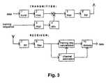
- Fig. 3shows a block diagram comprising those parts of a transmitter unit and a receiver unit of an embodiment of the present invention, which are essential for understanding the present invention.
- the transmitter unitcomprises a burst generating means 1 which generates a burst on the basis of input data supplied thereto.
- the generated burstis modulated in a first modulating means.
- a second modulating means 3is provided for separately modulating a supplied training sequence.
- the modulated training sequenceis attenuated in an attenuator 4 which, for example, may be adjustable.
- the attenuation factor of the attenuator 4is selected so as to minimize disturbance of the data burst and to ensure reliable data detection.
- the attenuated modulated training sequenceis superposed onto the modulated data burst. This can be effected by adding both modulated signals, for example.
- the superposition of the data burst and the training sequenceis preferably performed at intermediate frequency level.
- GMSKGaussian Minimum Shift Keying
- the superposition of the data burst and the training sequencemay also be performed at baseband level.
- the modulation methods of the training sequence and the data burstmay also differ from each other, as long as subsequent separation is possible without excessive deterioration.
- the resultant combined signalis filtered by a filtering means 5 in order to restrict the transmission bandwidth according to the corresponding system requirements.
- the combined and filtered TDMA signal obtained from the filtering means 5is then supplied to a radio frequency (RF) transmitting means 6 which transmits the combined signal as an RF burst using a transmitting antenna.
- RFradio frequency
- the receiver unit shown in the lower part of Fig. 3comprises an RF receiving means 7 which receives an RF burst with a receiving antenna.
- the RF receiving means 7demodulates the received RF burst by using a local oscillator (not shown).
- the demodulated TDMA signalis filtered by a filtering means 8 in order to remove unwanted frequency components.
- the received combined TDMA signalis branched and the superposed training sequence is extracted and detected by a channel estimating means 11 using a filtering means (not shown) such as an adapted filter.
- the kind of extractiondepends on the autocorrelation properties of the training sequence. If the training sequence exhibits good autocorrelation properties, then simple matched filter/correlation methods can be employed, i.e. the signal is correlated in the receiver with the known training sequence. Due to the good autocorrelation properties, the output of this correlation is the channel estimate plus noise generated due to the random data signal, interferences from other users and Gaussian noise.
- the training sequencecould be any random sequence, but then more complex estimation methods would be required. Therefore, good sequences are preferrred.
- the detected training sequenceis used by said channel estimation means 11 to measure desired parameters of the channel impulse response.
- the training sequenceis cancelled from the received data burst by a training sequence cancelling means 11.
- the cancellationmay be effected by an interference cancellation technique on the basis of the measured channel impulse response parameters which are supplied to the training sequence cancelling means 11 by the above mentioned channel estimating means 11.
- the training sequence cancelling means 11the training sequence can be regenerated and subtracted from the received signal before data detection.
- the training sequence cancellationmay be effected by simple cut-off or limiting techniques in case of constant envelope data modulation. Thereby, any disturbance of subsequent data detection can be prevented.
- a detector 10After the superposed training sequence has been cancelled from the received burst, data detection is performed in a detector 10 on the basis of the channel impulse response parameters which are also supplied to the detector 10 from the channel estimating means 11. Finally, the detector 10 outputs the received data. Conventional detectors such as MLSE-detectors (Viterbi), DFE-detectors, etc. may be used as the detector 10.
- the present inventioncould be further improved by providing a receiver in which iterations are employed.
- the channel estimation and the data detectionare initially performed, followed by an estimation of the received data, which can be used to regenerate the received data signal, i.e. the detected bits are modulated and filtered with the channel estimate.
- the regenerated data signalcan be subtracted from the received signal and a new channel estimation can be performed. In case most of the data bits are correct, this process improves the channel estimate. this leads to an improved training sequence cancellation and data detection.
- the iteration processcan be repeated several times until a desired improvement has been reached.
Landscapes
- Engineering & Computer Science (AREA)
- Signal Processing (AREA)
- Computer Networks & Wireless Communication (AREA)
- Time-Division Multiplex Systems (AREA)
- Digital Transmission Methods That Use Modulated Carrier Waves (AREA)
- Radio Relay Systems (AREA)
Abstract
Description
Claims (20)
- A TDMA method, comprising the step of:modulating a training sequence; andcharacterised by the step of:generating a TDMA burst by superposing said modulatedtraining sequence upon a data signal.
- A TDMA method according to claim 1,
wherein said training sequence is used for calculatingparameters of an impulse response of a transmission channel. - A TDMA method according to claims 1 or 2,
wherein said transmitting method is used in a GSM or aDCS system. - A TDMA method according to any one of the precedingsclaims,
wherein said training sequence is used for estimating achange in the channel inpulse response over the TDMA burstand/or a frequency error. - A TDMA method according to any one of the precedingclaims,
wherein said training sequence is a CAZAC sequence oran M sequence. - A TDMA method according to any one of the precedingclaims,
wherein said modulated training sequence is added to amodulated data signal in order to generate said TDMA burst. - A TDMA method according to claim 6,
wherein the power of said superposed training sequenceis smaller than the power of said modulated data signal. - A TDMA method according to any one of the precedingclaims,
wherein said training sequence is repeated periodicallywithin the length of said TDMA burst. - A TDMA method according to any one of the precedingclaims,
wherein the power of said superposed training sequenceis smaller than the power of said data signal. - A transmitter for a TDMA system, comprising:modulating means (3) for modulating a trainingsequence; andcharacterised by:superposing means for generating a TDMA burst bysuperposing said modulated training sequence upon a datasignal; andtransmitting means (6) for transmitting said TDMAburst.
- A transmitter according to claim 10,
wherein said modulating means (3) is operable so that said training sequence is modulated separatelyfrom said data signal. - A transmitter according to claim 10 or 11,
comprising another modulating means (2) for modulatingsaid data signal. - A transmitter according to any one of claims 10 to 12,
comprising an attenuator (4) for attenuating saidmodulated training sequence supplied from said modulatingmeans (3) before being superposed on said data signal. - A transmitter according to claim 13,
wherein said attenuator (4) is adjustable. - A receiver for a TDMA system, comprising:receiving means (7) for receiving a TDMA burst; andcharacterisedby extracting means (11) for extracting a trainingsequence superposed on the received TDMA burst; andcancelling means (9) for cancelling the superposedtraining sequence before data detection.
- A receiver according to claim 15,
wherein said extracting means (11) comprises afiltering means for extracting said training sequence. - A receiver according to claim 16,
wherein said filtering means is an adaptive filter. - A receiver according to any one of claims 15 to 17,
wherein said extracting means (11) is adapted tomeasure parameters of a channel impulse response on the basisof said extracted training sequence. - A receiver according to claim 18,
wherein said extracting means (11) is operable so that said parameters of said channel impulseresponse are supplied to said cancelling means (9) which isadapted to cancel said training sequence from said receivedTDMA burst by means of an interference cancellation techniquebased on said supplied parameters. - A receiver according to claims 18 or 19,
comprising a detector (10) for performing datadetection on the basis of said channel impulse responseparameters supplied thereto.
Applications Claiming Priority (1)
| Application Number | Priority Date | Filing Date | Title |
|---|---|---|---|
| PCT/EP1996/004969WO1998021847A1 (en) | 1996-11-13 | 1996-11-13 | Method, transmitter and receiver for transmitting training signals in a tdma transmission system |
Publications (2)
| Publication Number | Publication Date |
|---|---|
| EP0876719A1 EP0876719A1 (en) | 1998-11-11 |
| EP0876719B1true EP0876719B1 (en) | 2005-03-16 |
Family
ID=8166397
Family Applications (1)
| Application Number | Title | Priority Date | Filing Date |
|---|---|---|---|
| EP96938193AExpired - LifetimeEP0876719B1 (en) | 1996-11-13 | 1996-11-13 | Method, transmitter and receiver for transmitting training signals in a tdma transmission system |
Country Status (6)
| Country | Link |
|---|---|
| US (1) | US6337855B1 (en) |
| EP (1) | EP0876719B1 (en) |
| AT (1) | ATE291304T1 (en) |
| AU (1) | AU711253B2 (en) |
| DE (1) | DE69634496T2 (en) |
| WO (1) | WO1998021847A1 (en) |
Families Citing this family (27)
| Publication number | Priority date | Publication date | Assignee | Title |
|---|---|---|---|---|
| GB2321832B (en)* | 1997-01-30 | 1999-01-06 | Motorola Israel Ltd | Method to train a radio |
| GB2329796A (en)* | 1997-09-29 | 1999-03-31 | Motorola Ltd | Increased data rate by reduction of training data |
| DE19746652A1 (en)* | 1997-10-22 | 1999-04-29 | Heinz Brych | Data transmitting and receiving and operating circuit |
| US6438121B1 (en)* | 1997-12-19 | 2002-08-20 | Hughes Electronics Corporation | Recognition and utilization of auxiliary error control transmissions |
| FI112739B (en) | 1998-05-25 | 2003-12-31 | Nokia Corp | Method and apparatus for detecting an interfering signal in a radio receiver |
| US7494488B2 (en)* | 1998-05-28 | 2009-02-24 | Pearl Technology Holdings, Llc | Facial tissue strengthening and tightening device and methods |
| FI105516B (en)* | 1998-07-24 | 2000-08-31 | Nokia Networks Oy | Method and packet radio system for transmitting modulation and signaling data |
| US6760311B1 (en)* | 1998-11-20 | 2004-07-06 | Ericsson Inc. | Thermal transmission control of wireless data modem |
| FI108494B (en)* | 1998-12-22 | 2002-01-31 | Nokia Corp | Signaling procedure and telecommunication system |
| DE69922342T2 (en)* | 1999-04-19 | 2005-05-12 | Alcatel | TDMA multipoint-to-point system using a special burst structure and associated transmitters |
| US6370205B1 (en)* | 1999-07-02 | 2002-04-09 | Telefonaktiebolaget Lm Ericsson (Publ) | Method and apparatus for performing DC-offset compensation in a radio receiver |
| JP3190318B2 (en)* | 1999-07-07 | 2001-07-23 | 三菱電機株式会社 | Frequency error estimating apparatus and frequency error estimating method |
| US6185227B1 (en) | 1999-07-22 | 2001-02-06 | Nokia Networks Oy | Method and packet radio system for transmitting modulation and signalling information |
| AU1158300A (en)* | 1999-10-27 | 2001-05-08 | Nokia Corporation | Dc offset correction in a mobile communication system |
| US6628706B1 (en)* | 1999-12-06 | 2003-09-30 | Telefonaktiebolaget Lm Ericsson (Publ) | Method and apparatus for transforming a channel estimate |
| US6594793B1 (en) | 2000-09-08 | 2003-07-15 | Ericsson Inc. | Methods and systems for multiplexing and decoding variable length messages in digital communications systems |
| US6928120B1 (en)* | 2000-09-25 | 2005-08-09 | Cingular Wireless Ii, Llc | Methods and apparatus for use in reducing residual phase error in OFDM communication signals |
| GB2375272B (en)* | 2001-04-30 | 2003-11-19 | Lucent Technologies Inc | A frequency estimator for use in a receiver of packetised data, the receiver and a method of reception |
| US8238404B2 (en)* | 2001-10-23 | 2012-08-07 | Koninklijke Philps Electronics N.V. | Method to improve ATSC-VSB transceiver performance employing a time-frequency waveform processor |
| KR100605810B1 (en)* | 2003-12-20 | 2006-07-31 | 삼성전자주식회사 | How to transmit / receive data in portable terminal |
| GB2423437B (en)* | 2005-02-16 | 2007-06-13 | Toshiba Res Europ Ltd | Communications system, method and device |
| US20070135876A1 (en)* | 2005-12-08 | 2007-06-14 | Weber Paul J | Acne and skin defect treatment via non-radiofrequency electrical current controlled power delivery device and methods |
| WO2010030399A1 (en) | 2008-09-12 | 2010-03-18 | Qualcomm Incorporated | A method and apparatus for signaling to a mobile device which set of training sequence codes to use for a communication link |
| CN101938283B (en)* | 2009-06-29 | 2013-09-04 | 国基电子(上海)有限公司 | Multi-carrier interference eliminating circuit and a signal receiving and transmitting system using same |
| KR101581811B1 (en)* | 2010-01-29 | 2016-01-04 | 삼성전자주식회사 | Method and apparatus for transmitting and receiving training sequence code in communication system |
| GB2515801A (en) | 2013-07-04 | 2015-01-07 | Sony Corp | Transmitter and receiver and methods of transmitting and receiving |
| DE102013220912A1 (en) | 2013-10-15 | 2015-04-16 | Continental Automotive Gmbh | System and method for data transmission with receiver-side useful signal detection |
Family Cites Families (9)
| Publication number | Priority date | Publication date | Assignee | Title |
|---|---|---|---|---|
| IT1128766B (en) | 1980-04-04 | 1986-06-04 | Cselt Centro Studi Lab Telecom | PROCEDURE AND DEVICE FOR THE SYNCHRONIZATION OF THE PLOT OF AN ADDITIONAL INFORMATION SIGNAL TRANSMITTED TO THE LEVEL DIVISION |
| JPS6163124A (en) | 1984-09-04 | 1986-04-01 | Mitsubishi Electric Corp | Time-division multidirectional digital communication equipment |
| JPH0614627B2 (en) | 1985-06-04 | 1994-02-23 | 富士通株式会社 | Modem training methods |
| JPS6247236A (en) | 1985-08-26 | 1987-02-28 | Nec Corp | Data transmission system |
| DE3644175A1 (en)* | 1986-12-23 | 1988-07-14 | Messerschmitt Boelkow Blohm | Method for transmitting data using satellites |
| US5390216A (en)* | 1991-11-02 | 1995-02-14 | Robert Bosch Gmbh | Synchronization method for a mobile radiotelephone |
| FI108975B (en)* | 1993-03-09 | 2002-04-30 | Nokia Corp | Exercise sequence in a digital cellular radio telephone system |
| JP2571008B2 (en)* | 1993-12-24 | 1997-01-16 | 日本電気株式会社 | Adaptive maximum likelihood sequence estimator |
| US5905733A (en)* | 1996-12-03 | 1999-05-18 | Ericsson Inc. | Method and apparatus for distinguishing in-band signaling from user data |
- 1996
- 1996-11-13EPEP96938193Apatent/EP0876719B1/ennot_activeExpired - Lifetime
- 1996-11-13ATAT96938193Tpatent/ATE291304T1/ennot_activeIP Right Cessation
- 1996-11-13AUAU75707/96Apatent/AU711253B2/ennot_activeCeased
- 1996-11-13USUS09/101,993patent/US6337855B1/ennot_activeExpired - Fee Related
- 1996-11-13WOPCT/EP1996/004969patent/WO1998021847A1/enactiveIP Right Grant
- 1996-11-13DEDE69634496Tpatent/DE69634496T2/ennot_activeExpired - Lifetime
Also Published As
| Publication number | Publication date |
|---|---|
| ATE291304T1 (en) | 2005-04-15 |
| EP0876719A1 (en) | 1998-11-11 |
| DE69634496D1 (en) | 2005-04-21 |
| WO1998021847A1 (en) | 1998-05-22 |
| AU7570796A (en) | 1998-06-03 |
| US6337855B1 (en) | 2002-01-08 |
| DE69634496T2 (en) | 2006-04-27 |
| AU711253B2 (en) | 1999-10-07 |
Similar Documents
| Publication | Publication Date | Title |
|---|---|---|
| EP0876719B1 (en) | Method, transmitter and receiver for transmitting training signals in a tdma transmission system | |
| RU2144733C1 (en) | Signal channel packet for communication system which reference signal id modulated by time- dependent function | |
| AU610003B2 (en) | Timing and carrier recovery in tdma without preamble sequence | |
| RU2152686C1 (en) | Coherent receiver of code-division multiple- access system using sequence for direct demodulation of transmission line of earth- aircraft communication | |
| JP3036750B2 (en) | Time division multiple access (TDMA) radio system receiver, demodulator for the time division multiple access (TDMA) radio system receiver, and polyphase demodulation method in the time division multiple access (TDMA) radio system receiver | |
| USRE42538E1 (en) | System and method for signal synchronization in a communication system | |
| KR970007362B1 (en) | Equalizing device in receiver | |
| US5005188A (en) | Channel estimation and detection for digital communication systems | |
| KR100614553B1 (en) | Method, apparatus and system for positioning frequency synchronizing signal | |
| MXPA98000853A (en) | Des-extendedor adapta | |
| US10594535B2 (en) | System and method for extracting satellite to ground link quality using satellite telemetry signal and low complexity receiver | |
| KR100567290B1 (en) | Method and apparatus for detecting frequency synchronization signal | |
| JPH0322954B2 (en) | ||
| US6249518B1 (en) | TDMA single antenna co-channel interference cancellation | |
| US7587191B2 (en) | High-quality detection based on sequential interference cancellation techniques | |
| EP0958666B1 (en) | Compensation of doppler shift in a mobile communication system | |
| JP4659317B2 (en) | Doppler diffusion estimation using the channel autocorrelation function hypothesis | |
| AU682689B2 (en) | CDMA communication system | |
| CN1068481C (en) | Selecting Receiver Paths Based on Burst Type in Time Division Multiple Access Receivers | |
| US6163534A (en) | Method for determining the speed of a terminal equipment and a receiver | |
| US6618453B1 (en) | Estimating interference in a communication system | |
| EP0931390B1 (en) | Improved synchronization of a receiver with a transmitter using nonlinear transformation metrics | |
| JPH06338915A (en) | Equipment and method for sampled signal detection time point determination in receiver | |
| WO1996013897A1 (en) | Communication device with reduced sensitivity to in-channel interference | |
| KR0131916B1 (en) | Random fm noise cancellation |
Legal Events
| Date | Code | Title | Description |
|---|---|---|---|
| PUAI | Public reference made under article 153(3) epc to a published international application that has entered the european phase | Free format text:ORIGINAL CODE: 0009012 | |
| AK | Designated contracting states | Kind code of ref document:A1 Designated state(s):AT BE CH DE DK ES FI FR GB GR IE IT LI LU MC NL PT SE | |
| AX | Request for extension of the european patent | Free format text:AL PAYMENT 971217;LT PAYMENT 971217;LV PAYMENT 971217;RO PAYMENT 971217;SI PAYMENT 971217 | |
| 17P | Request for examination filed | Effective date:19971217 | |
| RAP1 | Party data changed (applicant data changed or rights of an application transferred) | Owner name:NOKIA NETWORKS OY | |
| RAP1 | Party data changed (applicant data changed or rights of an application transferred) | Owner name:NOKIA CORPORATION | |
| GRAP | Despatch of communication of intention to grant a patent | Free format text:ORIGINAL CODE: EPIDOSNIGR1 | |
| GRAS | Grant fee paid | Free format text:ORIGINAL CODE: EPIDOSNIGR3 | |
| GRAA | (expected) grant | Free format text:ORIGINAL CODE: 0009210 | |
| AK | Designated contracting states | Kind code of ref document:B1 Designated state(s):AT BE CH DE DK ES FI FR GB GR IE IT LI LU MC NL PT SE | |
| AX | Request for extension of the european patent | Extension state:AL LT LV RO SI | |
| PG25 | Lapsed in a contracting state [announced via postgrant information from national office to epo] | Ref country code:NL Free format text:LAPSE BECAUSE OF FAILURE TO SUBMIT A TRANSLATION OF THE DESCRIPTION OR TO PAY THE FEE WITHIN THE PRESCRIBED TIME-LIMIT Effective date:20050316 Ref country code:LI Free format text:LAPSE BECAUSE OF FAILURE TO SUBMIT A TRANSLATION OF THE DESCRIPTION OR TO PAY THE FEE WITHIN THE PRESCRIBED TIME-LIMIT Effective date:20050316 Ref country code:IT Free format text:LAPSE BECAUSE OF FAILURE TO SUBMIT A TRANSLATION OF THE DESCRIPTION OR TO PAY THE FEE WITHIN THE PRE;WARNING: LAPSES OF ITALIAN PATENTS WITH EFFECTIVE DATE BEFORE 2007 MAY HAVE OCCURRED AT ANY TIME BEFORE 2007. THE CORRECT EFFECTIVE DATE MAY BE DIFFERENT FROM THE ONE RECORDED.SCRIBED TIME-LIMIT Effective date:20050316 Ref country code:FI Free format text:LAPSE BECAUSE OF FAILURE TO SUBMIT A TRANSLATION OF THE DESCRIPTION OR TO PAY THE FEE WITHIN THE PRESCRIBED TIME-LIMIT Effective date:20050316 Ref country code:ES Free format text:LAPSE BECAUSE OF FAILURE TO SUBMIT A TRANSLATION OF THE DESCRIPTION OR TO PAY THE FEE WITHIN THE PRESCRIBED TIME-LIMIT Effective date:20050316 Ref country code:CH Free format text:LAPSE BECAUSE OF FAILURE TO SUBMIT A TRANSLATION OF THE DESCRIPTION OR TO PAY THE FEE WITHIN THE PRESCRIBED TIME-LIMIT Effective date:20050316 Ref country code:BE Free format text:LAPSE BECAUSE OF FAILURE TO SUBMIT A TRANSLATION OF THE DESCRIPTION OR TO PAY THE FEE WITHIN THE PRESCRIBED TIME-LIMIT Effective date:20050316 Ref country code:AT Free format text:LAPSE BECAUSE OF FAILURE TO SUBMIT A TRANSLATION OF THE DESCRIPTION OR TO PAY THE FEE WITHIN THE PRESCRIBED TIME-LIMIT Effective date:20050316 | |
| REG | Reference to a national code | Ref country code:GB Ref legal event code:FG4D | |
| REG | Reference to a national code | Ref country code:CH Ref legal event code:EP | |
| REG | Reference to a national code | Ref country code:IE Ref legal event code:FG4D | |
| REF | Corresponds to: | Ref document number:69634496 Country of ref document:DE Date of ref document:20050421 Kind code of ref document:P | |
| PG25 | Lapsed in a contracting state [announced via postgrant information from national office to epo] | Ref country code:GR Free format text:LAPSE BECAUSE OF FAILURE TO SUBMIT A TRANSLATION OF THE DESCRIPTION OR TO PAY THE FEE WITHIN THE PRESCRIBED TIME-LIMIT Effective date:20050616 Ref country code:DK Free format text:LAPSE BECAUSE OF FAILURE TO SUBMIT A TRANSLATION OF THE DESCRIPTION OR TO PAY THE FEE WITHIN THE PRESCRIBED TIME-LIMIT Effective date:20050616 | |
| LTIE | Lt: invalidation of european patent or patent extension | Effective date:20050316 | |
| NLV1 | Nl: lapsed or annulled due to failure to fulfill the requirements of art. 29p and 29m of the patents act | ||
| PG25 | Lapsed in a contracting state [announced via postgrant information from national office to epo] | Ref country code:PT Free format text:LAPSE BECAUSE OF FAILURE TO SUBMIT A TRANSLATION OF THE DESCRIPTION OR TO PAY THE FEE WITHIN THE PRESCRIBED TIME-LIMIT Effective date:20050907 | |
| REG | Reference to a national code | Ref country code:CH Ref legal event code:PL | |
| PG25 | Lapsed in a contracting state [announced via postgrant information from national office to epo] | Ref country code:GB Free format text:LAPSE BECAUSE OF NON-PAYMENT OF DUE FEES Effective date:20051113 | |
| PG25 | Lapsed in a contracting state [announced via postgrant information from national office to epo] | Ref country code:IE Free format text:LAPSE BECAUSE OF NON-PAYMENT OF DUE FEES Effective date:20051114 | |
| PG25 | Lapsed in a contracting state [announced via postgrant information from national office to epo] | Ref country code:MC Free format text:LAPSE BECAUSE OF NON-PAYMENT OF DUE FEES Effective date:20051130 Ref country code:LU Free format text:LAPSE BECAUSE OF NON-PAYMENT OF DUE FEES Effective date:20051130 | |
| PLBE | No opposition filed within time limit | Free format text:ORIGINAL CODE: 0009261 | |
| STAA | Information on the status of an ep patent application or granted ep patent | Free format text:STATUS: NO OPPOSITION FILED WITHIN TIME LIMIT | |
| 26N | No opposition filed | Effective date:20051219 | |
| EN | Fr: translation not filed | ||
| GBPC | Gb: european patent ceased through non-payment of renewal fee | Effective date:20051113 | |
| REG | Reference to a national code | Ref country code:IE Ref legal event code:MM4A | |
| PG25 | Lapsed in a contracting state [announced via postgrant information from national office to epo] | Ref country code:SE Free format text:LAPSE BECAUSE OF FAILURE TO SUBMIT A TRANSLATION OF THE DESCRIPTION OR TO PAY THE FEE WITHIN THE PRESCRIBED TIME-LIMIT Effective date:20050616 | |
| PG25 | Lapsed in a contracting state [announced via postgrant information from national office to epo] | Ref country code:FR Free format text:LAPSE BECAUSE OF NON-PAYMENT OF DUE FEES Effective date:20051130 | |
| PG25 | Lapsed in a contracting state [announced via postgrant information from national office to epo] | Ref country code:FR Free format text:LAPSE BECAUSE OF NON-PAYMENT OF DUE FEES Effective date:20050316 | |
| PGFP | Annual fee paid to national office [announced via postgrant information from national office to epo] | Ref country code:DE Payment date:20091105 Year of fee payment:14 | |
| REG | Reference to a national code | Ref country code:DE Ref legal event code:R119 Ref document number:69634496 Country of ref document:DE Effective date:20110601 Ref country code:DE Ref legal event code:R119 Ref document number:69634496 Country of ref document:DE Effective date:20110531 | |
| PG25 | Lapsed in a contracting state [announced via postgrant information from national office to epo] | Ref country code:DE Free format text:LAPSE BECAUSE OF NON-PAYMENT OF DUE FEES Effective date:20110531 |