EP0876177B1 - Multi-functional biomedical electrodes - Google Patents
Multi-functional biomedical electrodesDownload PDFInfo
- Publication number
- EP0876177B1 EP0876177B1EP96920352AEP96920352AEP0876177B1EP 0876177 B1EP0876177 B1EP 0876177B1EP 96920352 AEP96920352 AEP 96920352AEP 96920352 AEP96920352 AEP 96920352AEP 0876177 B1EP0876177 B1EP 0876177B1
- Authority
- EP
- European Patent Office
- Prior art keywords
- electrode
- conductors
- electrical
- conductor
- electrical conductor
- Prior art date
- Legal status (The legal status is an assumption and is not a legal conclusion. Google has not performed a legal analysis and makes no representation as to the accuracy of the status listed.)
- Expired - Lifetime
Links
Images
Classifications
- A—HUMAN NECESSITIES
- A61—MEDICAL OR VETERINARY SCIENCE; HYGIENE
- A61B—DIAGNOSIS; SURGERY; IDENTIFICATION
- A61B5/00—Measuring for diagnostic purposes; Identification of persons
- A61B5/24—Detecting, measuring or recording bioelectric or biomagnetic signals of the body or parts thereof
- A61B5/25—Bioelectric electrodes therefor
- A61B5/279—Bioelectric electrodes therefor specially adapted for particular uses
- A61B5/28—Bioelectric electrodes therefor specially adapted for particular uses for electrocardiography [ECG]
- A61B5/282—Holders for multiple electrodes
- A—HUMAN NECESSITIES
- A61—MEDICAL OR VETERINARY SCIENCE; HYGIENE
- A61N—ELECTROTHERAPY; MAGNETOTHERAPY; RADIATION THERAPY; ULTRASOUND THERAPY
- A61N1/00—Electrotherapy; Circuits therefor
- A61N1/02—Details
- A61N1/04—Electrodes
- A61N1/0404—Electrodes for external use
- A61N1/0472—Structure-related aspects
- A61N1/0492—Patch electrodes
- A—HUMAN NECESSITIES
- A61—MEDICAL OR VETERINARY SCIENCE; HYGIENE
- A61B—DIAGNOSIS; SURGERY; IDENTIFICATION
- A61B2562/00—Details of sensors; Constructional details of sensor housings or probes; Accessories for sensors
- A61B2562/02—Details of sensors specially adapted for in-vivo measurements
- A61B2562/0209—Special features of electrodes classified in A61B5/24, A61B5/25, A61B5/283, A61B5/291, A61B5/296, A61B5/053
- A61B2562/0215—Silver or silver chloride containing
- A—HUMAN NECESSITIES
- A61—MEDICAL OR VETERINARY SCIENCE; HYGIENE
- A61N—ELECTROTHERAPY; MAGNETOTHERAPY; RADIATION THERAPY; ULTRASOUND THERAPY
- A61N1/00—Electrotherapy; Circuits therefor
- A61N1/02—Details
- A61N1/04—Electrodes
- A61N1/0404—Electrodes for external use
- A61N1/0408—Use-related aspects
- A61N1/0412—Specially adapted for transcutaneous electroporation, e.g. including drug reservoirs
- A—HUMAN NECESSITIES
- A61—MEDICAL OR VETERINARY SCIENCE; HYGIENE
- A61N—ELECTROTHERAPY; MAGNETOTHERAPY; RADIATION THERAPY; ULTRASOUND THERAPY
- A61N1/00—Electrotherapy; Circuits therefor
- A61N1/02—Details
- A61N1/04—Electrodes
- A61N1/0404—Electrodes for external use
- A61N1/0408—Use-related aspects
- A61N1/0428—Specially adapted for iontophoresis, e.g. AC, DC or including drug reservoirs
- A—HUMAN NECESSITIES
- A61—MEDICAL OR VETERINARY SCIENCE; HYGIENE
- A61N—ELECTROTHERAPY; MAGNETOTHERAPY; RADIATION THERAPY; ULTRASOUND THERAPY
- A61N1/00—Electrotherapy; Circuits therefor
- A61N1/02—Details
- A61N1/04—Electrodes
- A61N1/0404—Electrodes for external use
- A61N1/0408—Use-related aspects
- A61N1/0456—Specially adapted for transcutaneous electrical nerve stimulation [TENS]
- A—HUMAN NECESSITIES
- A61—MEDICAL OR VETERINARY SCIENCE; HYGIENE
- A61N—ELECTROTHERAPY; MAGNETOTHERAPY; RADIATION THERAPY; ULTRASOUND THERAPY
- A61N1/00—Electrotherapy; Circuits therefor
- A61N1/02—Details
- A61N1/04—Electrodes
- A61N1/0404—Electrodes for external use
- A61N1/0408—Use-related aspects
- A61N1/046—Specially adapted for shock therapy, e.g. defibrillation
Definitions
- This inventionconcerns biomedical electrodes having multiple functions.
- diagnostic procedureswhere electrical signals or currents are received from a mammalian patient's body.
- diagnostic proceduresinclude electrocardiographic (ECG or EKG) diagnosis or monitoring of electrical wave patterns of a mammalian heart, irrespective of duration or circumstance.
- ECG or EKGelectrocardiographic
- the point of contact between medical equipment used in these procedures and the skin of the patientis usually some sort of biomedical electrode.
- Such an electrodetypically includes a conductor which must be connected electrically to the equipment, and an ionically conductive medium adhered to or otherwise contacting skin of a patient.
- ECGelectrocardiographs
- At least one biomedical electrode having an ionically-conductive medium containing an electrolyteis adhered to or otherwise contacting skin at a location of interest and also electrically connected to electrical diagnostic equipment.
- a critical component of the biomedical electrodeis the electrical conductor in electrical communication with the ionically-conductive medium and the electrical diagnostic equipment.
- biomedical electrodesrequire excellent electrical conductivity and minimal electrical resistance for biomedical electrodes, especially when faint electrical signals are received from the patient. For this reason, metals or carbon (especially graphite) are used. Among metals, silver is preferred because of its optimal conductivity. But biomedical electrodes which monitor a patient's conditions must have a stable half cell potential and be able to withstand the polarizing effects of a defibrillation procedure for a heart. For this reason, a metal halide, such as silver chloride, is preferably used with a metal conductor, such as silver, to create a depolarizable electrical conductor in biomedical electrodes which can monitor a heart.
- metal halidesuch as silver chloride
- the biomedical electrodehas employed a field of conductive hydrogel or adhesive to contact or adhere to mammalian skin and to receive the electrical signals and transmit them ionically to an electrical conductor for electrical connection to biomedical instrumentation.
- biomedical electrodesinclude U.S. Pat. Nos. 4,352,359 (Larimore); 4,524,087 (Engel); 4,539,996 (Engel); 4,554,924 (Engel); 4,848,348 (Carim); 4,848,353 (Engel); 5,012,810 (Strand et al.); 5,133,356 (Bryan et al.); 5,215,087 (Anderson et al.); and 5,296,079 (Duan et al.).
- Biomedical electrode constructionhas increasingly employed a tab/pad style of construction.
- a number of biomedical electrode constructionshave employed an insulative outer layer through which an electrically conductive tab extends to provide a low profile, multi-layer construction. Representative examples of such constructions are disclosed in the embodiments shown in U.S. Patent No. 5,012,810 (Strand et al.).
- Another low profile multi-layer constructionemploys an electrically conductive tab which remains below the surface of the outermost layer but is accessible to the outside through an aperture in the outermost layer.
- a representative example of this electrode constructionis disclosed in U.S. Patent No. 5,215,087 (Anderson et al.).
- biomedical electrode constructionsinvolve an elaborate placement of sponges in apertures to which an electrically conductive tab can contact even though that tab does not extend beneath the surface of the outer most layer.
- Representative examples of this constructionis found in U.S. Patent No. 3,977,392 (Manley), U.S. Patent No. 4,522,211 (Bare et al.) and U.S. Patent No. 4,838,273 (Cartmell).
- Another biomedical electrode constructionemploys a reservoir of conductive gel into which a lead wire can be inserted through an aperture, as disclosed in U.S. Patent No. 4,409,981 (Lundberg).
- Another biomedical electrode constructionemploys an aperture in communication with a conductive adhesive into which a lead wire can be inserted through the aperture, as disclosed in U.S. Patent No. 4,715,382 (Strand).
- DE 37 03 321 Adescribes a biomedical electrode in the form of a patch primarily used for transdermal delivery of a therapeutic drug by iontophoreses.
- the patchcomprises two electrodes, an electric current source connected with one of the electrodes and at least one ionic substance filled in a chamber of the patch.
- DE 195 03 341 Adiscloses a single biomedical electrode having two portions to provide a differing electrochemical potential, the single electrode comprising two electrical conductors of differing compositions and one field of ionically conductive medium of conductive hydrogel, wherein the two conductors are made from materials having different galvanic properties.
- biomedical electrodesare disposable and are generally disposed after a single use, cost/benefit analysis of biomedical electrode usage is continuously under health care cost scrutiny. The more that a single biomedical electrode can provide for the least amount of cost is a goal of both manufacturers and the consumers they serve.
- diagnostic biomedical electrodesFor example, about 10 diagnostic biomedical electrodes are required for each electrocardiogram (ECG) procedure.
- ECGelectrocardiogram
- Such diagnostic biomedical electrodesare presently designed for a single purpose and for a single use, making the cost of such electrodes to customers very sensitive to manufacturing techniques and performance features.
- the cost of manufactureoutweighs the performance properties of the electrode.
- the present inventionsolves problems confronting manufacturers and users of biomedical electrodes by combining multiple electrode functions on a single, inexpensive electrode due to a differing electrochemical potential on the electrode.
- One aspect of the inventionis a multi-functional, differing electrochemical potential biomedical electrode.
- Multi-functionalmeans that a single biomedical electrode of the present invention can operate or provide more than one function in conjunction with its use with the body of a patient.
- Nonlimiting examples of multi-functional uses of a biomedical electrode of the present inventioninclude the ability to both deliver and receive electrical signals to and from the body of a patient; the ability to provide both a polarizable portion and a non-polarizable portion of a biomedical in communication with the body of a patient; and the ability to provide a galvanic circuit and some monitoring or therapeutic activity with the body of a patient.
- a patientcan be any animal for which biomedical electrodes can be used.
- “Differing electrochemical potential”means that one combination of electrically conductive material and ionically conductive medium on one portion of the electrode differs in electrochemical potential from a second combination of electrically conductive material and ionically conductive medium on another portion of the same electrode.
- the difference in electrochemical potentialcan be provided by differences in the respective electrically conductive materials, by differences in the respective ionically conductive media, or by differences in both the respective electrically conductive materials and the ionically conductive media.
- this biomedical electrodeis contemplated based on the twin goals of using two portions of an electrode having a differing electrochemical potential to provide the means of electrical communication in the biomedical electrode and of performing more than one type of electrical communication by one electrode.
- One embodiment of a multi-functional, differing electrochemical potential biomedical electrodecomprises a biomedical electrode having two portions to provide a differing electrochemical potential, wherein the electrode comprises at least two electrical conductors of differing compositions.
- a multi-functional, differing electrochemical potential biomedical electrodecomprises a biomedical electrode having two portions to provide a differing electrochemical potential, wherein the electrode comprises at least two ionically conductive media of differing compositions.
- biomedical electrodeOne feature of the biomedical electrode is the ability to manufacture the biomedical electrode with known electrically conductive materials and known ionically conductive media and with known manufacturing techniques but in new combinations previously unknown and unexpected beneficial in use.
- biomedical electrodeAnother feature of the biomedical electrode is the ability to perform more than one means of electrical communication concurrently, intermittently, or episodically to and from the biomedical electrode in contact with the body of a patient.
- a single biomedical electrode contemplated in the present inventioncan provide both electrocardiographic monitoring and pacing therapy at the same time or as needed.
- biomedical electrodeAnother feature of the biomedical electrode is the ability of conductors of different materials, ionically conductive media of different materials, or both, on a single electrode to create a galvanic circuit when in contact with skin of a patient.
- This galvanic circuitcan be used for a variety of purposes due to the stored energy inherently present in the two different conductor materials, the two different ionically conductive media, or both.
- An advantage of the biomedical electrode of the present inventionis the reduction of the numbers of types of biomedical electrodes that must be constructed to suit various consumer needs. This advantage benefits both the manufacturer and the consumer for inventory control, improving the cost/benefit analysis confronting the health care industry.
- the fields of ionically conductive mediaare shown within the perimeter of the electrical conductors. However, as known to those skilled in the art, the fields of conductive media normally extend to and preferably extend beyond the perimeter of the electrical conductors.
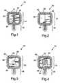
- a biomedical electrode 10is shown from the bottom side that contacts the body of a patient.
- Electrode 10comprises an electrically insulative backing 12 in the form of a pad portion 14 and a tab portion 16.
- Backing 12optionally has a field 18 ofbiocompatible pressure sensitive adhesive on its bottom surface.
- Multiple, contiguous electrical conductors 20 and 22contact the backing 12 (preferably adhering to field 18) on the pad portion 14 and extend to the tab portion 16.
- Two discontiguous ionically conductive media fields 24 and 26 of conductive hydrogel or adhesivecontact and preferably completely covers or extends beyond the perimeter of contiguous conductors 20 and 22, respectively in pad portion 14.
- the fields 18, 24, and 26are protected by a conventional release liner (not shown).
- Conductors 20 and 22can be made from different compositions of electrically conductive materials when the differing electrochemical potential is principally derived from the conductor portions of the electrode 10.
- One conductoris constructed from materials that are more galvanically active than the other conductor.
- one conductoris constructed from materials that are more electron donating than the other conductor.
- one conductoris constructed from galvanically active materials with the other conductor being constructed from galvanically inactive materials.
- the choice of materials for conductors 20 and 22can vary according to the needs of those skilled in the art of making and using biomedical electrodes.
- an acceptable biomedical electrodecould be made using differing conductors where one conductor was more galvanically active than the other conductor in order to establish a weak galvanic circuit formed from the contiguity of the two conductors 20 and 22 and the body of a patient contacting different fields 24 and 26 of conductive adhesive.
- creation of a galvanic circuitcan have several benefits for multifunctional biomedical electrodes.
- Nonlimiting examples of electrically conductive materials used in the construction of conductors 20 and 22include galvanically active metals (e.g., zinc, magnesium, tin, aluminum, and silver); galvanically inactive metals (e.g., platinum, gold, and selected alloys such as stainless steels); galvanically inactive inorganic oxides (e.g., manganese dioxide); carbon (e.g., graphite) and combinations thereof
- galvanically active metalse.g., zinc, magnesium, tin, aluminum, and silver
- galvanically inactive metalse.g., platinum, gold, and selected alloys such as stainless steels
- galvanically inactive inorganic oxidese.g., manganese dioxide
- carbone.g., graphite
- the two conductors 20 and 22are constructed with one electrically conductive material capable of donating electrons with the other electrically conductive material capable of accepting electrons.
- one electrically conductive material capable of donating electronswith the other electrically conductive material capable of accepting electrons.
- graphite in conductor 20accepts electrons given by silver in conductor 22.
- This miniature battery formed from a galvanic circuitcan both treat a patient, restore a monitoring function after defibrillation of the heart of a patient, and can power other therapy functions resident to or connected by circuitry to electrode 10.
- the electrode 10can also be reconditioned by the biomedical instrumentation.
- Other examples for conductor 22 as an electron donorare zinc, aluminum, tin, and magnesium
- examples for conductor 20 as an electron acceptorare silver/silver chloride and tin/stannic chloride.
- the two conductors 20 and 22are constructed with one electrically conductive material being galvanically active and the other material being galvanically inactive.
- the graphite conductor 20/ silver conductor 22 example in the preceding paragraphalso is applicable in this preferred construction to maximize the stored energy available in electrode 10.
- the present inventionunexpectedly finds advantages to the use of a layer of galvanically active metal contacting backing with a layer of galvanically inactive material covering the metal and contacting ionically conductive media.
- This embodiment of the present inventionadditionally contemplates any combination of galvanically active materials with galvanically inactive materials where the latter form the layer which contacts the conductive hydrogel or adhesive.
- the galvanically active metalis aluminum or silver and the galvanically inactive material is graphite, which in this context contemplates graphite also serving as a catalytic surface for the underlying metal.
- the galvanically active metalis silver.
- the galvanically active metalcan be of lower quality and cost, if graphite is the outer layer. An expensive conductor can be constructed without a functional decrease in acceptable performance.
- the galvanically active metal layercan range from about 100 nm to about 500 ⁇ m and preferably ranges from about 300 nm to about 300 ⁇ m. with the galvanically inactive material in a dried thickness ranging from about 1 ⁇ m to about 1 mm, and preferably in a thickness of about 200 ⁇ m.
- At least a portion of conductors 20 and 22 at tab portion 16can be contacted by a clamp or connector for electrical communication with biomedical electrical instrumentation, either to transmit energy into a body such as that used in transcutaneous electrical nerve stimulation or for receiving electrical signals from the body such as that used in electrocardiography.
- tab portion 16can have a stud/eyelet combination known to those skilled in the art to provide a snap connection at each conductor 20 and 22.
- the perimeter of backing 12has field 18 of pressure sensitive adhesive extending beyond the perimeter of conductors 20 and 22 such that field 18 becomes a skirt of pressure sensitive adhesive to adhere electrode 10 to skin of a patient.
- Nonlimiting examples of a suitable backing for use in the present inventionare medical-grade pressure sensitive adhesive tapes such as those commercially available under the brands “Blenderm” or “Durapore” or a melt blown polyurethane material having a pressure sensitive adhesive coating on its major surface, such as that disclosed in U.S. Patent No. 5,230,701 (Riedel).
- Backing 12has a thickness ranging from about 0.02 mm to about 0.89 mm and preferably 0.35 mm in order to provide a low profile layer of the multi-layer construction.
- Fields 24 and 26can be made from the same or different ionically conductive media depending on which embodiment of the differing electrochemical potential electrode is desired. If the same, then different performances of electrode 10 resides in the choices of conductors 20 and 22 to provide a differing electrochemical potential electrode. If different, then different performances of the conductors on the electrode 10 are also affected by the different ionically conductive media fields 24 and 26, whether conductors 20 and 22 are made from the same material.
- Nonlimiting examples of ionically conductive media useful as either field 24 or field 26, or both, in electrode 10 of the present inventioninclude those ionically conductive compositions disclosed in U.S. Patent Nos. 4,524,087 (Engel), 4,539,996 (Engel), 4,848,353 (Engel); 4,846,185 (Carim); 5,225,473 (Duan); 5,276,079 (Duan et al.); 5,338,490 (Dietz et al.); 5,362,420 (Itoh et al.); 5,385,679 (Uy et al.); copending, coassigned applications PCT Publication Nos.
- field 24 and field 26can be selected from different ionically conductive media from any combination of the compositions disclosed above.
- U.S. Pat. No. 4,846,185discloses the use of a redox couple containing electrolyte composition where one field 24 can have one composition of the couple and the other field 26 can have the composition of the redox couple.
- a reducible composition for field 26comprises an aqueous conductive adhesive with dissolved oxygen therein.
- compositions for field 24that provides ions, such as hydronium ions, to the corresponding electrical conductor and the use of a composition for field 26 that provides species that will form chemical bonds with ions from the corresponding electrical conductor.
- ionssuch as hydronium ions
- composition for field 26that provides species that will form chemical bonds with ions from the corresponding electrical conductor.
- Nonlimiting examples of this embodimentare the use of hydroxyl ions to form metal hydroxides in the ionic field and the use of carboxylate groups such as in the compositions disclosed in U.S. Pat. No. 4,524,087 (Engel) that complex with ions of or from the electrical conductor.
- Other complexing agentsare known as chelating agents such as EDTA, citrate salts, and the like.
- Thickness of the ionically conductive media fields 24 and 26can range from about 0.25 mm to about 2.5 mm and preferably 0.63 mm in order to maintain a low profile, multi-layer biomedical electrode construction.
- a typical release lineris a siliconized paper commercially available as PolyslikTM liner from Rexam Release of Oakbrook, Illinois.
- Electrode 30comprises an electrically insulative backing 32 having a pad portion 34 and a tab portion 36.
- a field 38 of biocompatible pressure sensitive adhesiveoptionally covers backing 32 and provides adhesiveness of electrode 30 for contact with the body of a patient.
- Electrode 30differs from electrode 10, in that conductors 40 and 42 are discontiguous and separated so that there is no electrically contact between their adjacent perimeters. Electrode 30 also differs from electrode 10, in that there is a single field 44 of ionically conductive medium contacting and preferably completely covering or extending beyond the perimeter of both conductors 40 and 42 in pad portion 34.
- Electrode 30provides a different geometry for the creation of a galvanic circuit, because electrode 30 does not rely on the body of a patient to provide the completion of the galvanic circuit. Rather, electrical connection to a clamp, other electrical devices, or the biomedical instrumentation completes the circuit.
- Materials for electrode 30can be any of the materials described above for electrode 10 and can be chosen in the same way for the same reasons by one skilled in the art.
- conductors 40 and 42contain silver and graphite, respectively.
- Electrode 50comprises an electrically insulative backing 52 having a pad portion 54 and a tab portion 56.
- a field 58 of biocompatible pressure sensitive adhesiveoptionally covers backing 52 and provides adhesiveness of electrode 50 for contact with the body of a patient.
- Electrode 50differs from electrode 10, in that conductor 60 surrounds conductor 62. Electrode also differs from electrode 10, in that there is a single field 64 of ionically conductive medium contacting and preferably completely covering or extending beyond the perimeter of both conductors 60 and 62 in pad portion 54.
- Electrode 50provides a different geometry for the use of combination electrode where the use of conductor 60 is primarily at the perimeter of conductor 60 in a manner as described and utilized in U.S. Pat. No. 5,337,748 (McAdams et al.) and the Clare patent described above.
- the non-perimeter portions of conductor 60do not substantially contribute to the function of electrode 50 for the purposes of defibrillation because the majority of the current will flow at the edges of a sheet conductor, not at its central area.
- conductor 62which can rely on conductor 60 for electrical connection or can use a separate electrical connection (not shown).
- electrode 50can be concurrent uses such as having conductor 60 be a dispersive plate for electrosurgery and having conductor 62 be a monitoring electrode during electrosurgery. Because conductors 60 and 62 are contiguous and field 64 of ionically conductive media contacts both conductors 60 and 62, a galvanic circuit is created within electrode 50.
- materials for electrode 50can be any of the materials described above for electrode 10.
- conductors 60 and 62contain aluminum and graphite, respectively.
- graphite conductor 62could also contain a third metal or metal/metal salt such as Ag/AgCl.
- Electrode 70comprises an electrically insulative backing 72 having a pad portion 74 and a tab portion 76.
- a field 78 of biocompatible pressure sensitive adhesiveoptionally covers backing 72 and provides adhesiveness of electrode 70 for contact with the body of a patient.
- Electrode 70differs from electrode 50, in that conductor 80 surrounds an aperture 82 in which a second conventional biomedical electrode 84 can reside. Electrode 70 also differs from electrode 50, in that there is a single field 86 of ionically conductive medium contacting and preferably completely covering or extending beyond the perimeter of conductor 80 in pad portion 74 but not aperture 82.
- Biomedical electrode 84can be a conventional biomedical electrode known to those skilled in the art or can be an electrode of this invention such as electrode 10 or 30. Because electrode 84 resides in aperture 82 of electrode 70, for purposes of this invention as alternative embodiment to electrode 50, this combination of electrode 70 and electrode 84 is considered a multi-functional, multiple conductor electrode within the scope of the present invention.
- electrode 70can be concurrent uses such as having conductor 80 be a dispersive plate for electrosurgery and having electrode 84 be a monitoring electrode during electrosurgery. Because conductor 80 and electrode 84 are discontiguous and field 86 of ionically conductive media contacts only conductor 80, a galvanic circuit is not possible. However, a galvanic circuit can be formed if desired by connecting the leads to the conductor 80 and electrode 84 externally, such as at the biomedical instrumentation.
- materials for electrode 50can be any of the materials described above for electrode 10.
- Electrodes 10, 30, 50, and 70can be made using conventional tab/pad style electrodes as described in those patents identified in the Background of the Invention. Generally, multiple layered electrodes are assembled from rolls of starting materials for insulative backing, upon which is coated or painted conductors, upon which is coated or cured ionically conductive media. Generally, an array of electrodes are constructed in line and cut into individual electrodes on a single release liner.
- Materials for conductors 20, 22, 40, 42, 60, 62, and 80can be formed from inks, paints, or laminates.
- conductorsare formed from electrically conductive inks printed in registration on a backing.
- Commercially available inks for biomedical electrodesinclude Ercon branded inks, Acheson Colloid branded inks, as well as those ink sources identified in the patents identified in the Background of the Invention above.
- Electrodes 10, 30, 50, or 70can be employed to make electrodes 10, 30, 50, or 70.
- One skilled in the art of making electrodescan select from a variety of machinery manufacturers and manufacturing techniques to minimize manufacturing expense and waste.
- Some types of machineryare disclosed in U.S. Pat. Nos. 4,715,382 (Strand); 5,133,356 (Bryan et al.); and copending, coassigned PCT publication WO 96/15715.
- Another method of manufacturing biomedical electrodesis disclosed in U. S. Pat. No. 5,352,315 (Carrier et al.)
- Multi-function, multiple conductor biomedical electrodes of the present inventioncan be used for a variety of purposes according to the needs of consumers in the health care industry.
- Nonlimiting examples of uses of electrodes 10, 30, 50, and 70include combination biomedical electrodes for diagnosis/monitoring of bioelectric signals from a body and therapeutic delivery of electrical signals into a body; providing a combination of an electrode signature or other electrode performance information for adaptive/intelligent biomedical instrumentation while also diagnosing or monitoring the patient; providing a combination of monitoring a patient at the area where a dispersive plate electrode is being used for electrosurgery; monitoring a patient at the area where an external cardiac pacing electrode is being used or where an external defibrillation electrode is being used.
- Nonlimiting examples of delivering of electrical signals to a patientinclude TENS, transdermal drug delivery, electroporation, iontophoresis, external cardiac pacing, electrophysiological assessement, and reducing impedance or otherwise conditioning skin of a patient.
- a combination electrodecan both provide monitoring functions and iontophoresis. If electrodes 10 or 30 are used, a galvanic circuit can be employed to power the delivery of a pharmaceutical or other therapeutic agent in the iontophoretic function of electrode 10 or 30. Otherwise, biomedical instrumentation can be used to power electrode 10 or 30.
- a combination electrode 10 or 30 with one conductor containing silver/silver chloride and another conductor containing graphitecan employ the galvanic circuit described above to restore the silver chloride after a defibrillation of a patient using electrode 10 or 30 functioning as a pacing or defibrillation electrode in combination with a monitoring electrode that requires defibrillation recovery properties to meet Association for the Advancement of Medical Instrumentation (AAMI) standards.
- AAMIAdvancement of Medical Instrumentation
- a combination electrode 10 or 30 with one conductor containing a galvanically active material and the other conductor containing a galvanically inactive material with an appropriate electrolytecan function as a self-powered monitoring electrode and battery for powering other circuitry for remote telemetric communication of the condition of a patient, where electricity and/or telephone communications are lacking or not needed. Battlefield triage could benefit from a self-powered monitoring electrode.
- Nonlimiting examples of uses of providing unique electrode identification information (an "electrode signature") or other electrode performance information for adaptive/intelligent biomedical instrumentationinclude identification of the proper electrode for usage, continued performance of the electrode during usage, alarm conditions when the performance of the electrode has expired or is substandard, and other interaction conditions with cables and leadwires between the electrode and biomedical instrumentation.
Landscapes
- Health & Medical Sciences (AREA)
- Life Sciences & Earth Sciences (AREA)
- Public Health (AREA)
- Engineering & Computer Science (AREA)
- Biomedical Technology (AREA)
- Veterinary Medicine (AREA)
- Animal Behavior & Ethology (AREA)
- General Health & Medical Sciences (AREA)
- Cardiology (AREA)
- Radiology & Medical Imaging (AREA)
- Nuclear Medicine, Radiotherapy & Molecular Imaging (AREA)
- Physics & Mathematics (AREA)
- Biophysics (AREA)
- Pathology (AREA)
- Heart & Thoracic Surgery (AREA)
- Medical Informatics (AREA)
- Molecular Biology (AREA)
- Surgery (AREA)
- Electrotherapy Devices (AREA)
- Measurement And Recording Of Electrical Phenomena And Electrical Characteristics Of The Living Body (AREA)
Description
Claims (4)
- A single biomedical electrode comprising an electrically insulativebacking having a pad portion and a tab portion, the single electrode also having acombination selected from the group consisting of(a) at least two electrical conductors of differing compositions and differing electrochemical potentialscontacting one field of ionically conductive medium of conductivehydrogel or adhesive, wherein one of the differing compositions is carbonor an inorganic oxide and the other differing composition is a metal andwherein the electrical conductors are discontiguous and separate from oneanother,(b) Multiple contiguous electrical conductors on the pad portion andextending to the tab portion, at least two discontiguous fields of ionicallyconductive media of differing compositions and differing electrochemical potentials of hydrogel or adhesivewherein one field of ionically conductive medium contacts one contiguouselectrical conductor and wherein one other ionically conductive mediumcontacts another contiguous electrical conductor,(c) at least two electrical conductors of differing compositions and differing electrochemical potentials, oneelectrical conductor surrounding the other electrical conductor, a field ofionically conductive medium contacting both electrical conductors, and(d) at least two electrical conductors of differing compositions and differing electrochemical potentials, oneelectrical conductor surrounding the other electrical conductor, a field ofionically conductive medium contacting one of the electrical conductors,and wherein the ionically conductive medium comprises an aperture inwhich the other electrical conductor resides.
- The biomedical electrode of Claim 1 , wherein one electrical conductor ismore galvanically active than the other electrical conductor or conductors.
- The biomedical electrode of Claim 2, wherein the one electrical conductoris more electron donating than the other electrical conductor or conductors.
- The biomedical electrode of Claim 1, wherein the one electrical conductorcontains a galvanically active material and the other electrical conductor or conductorscontain(s) a galvanically inactive material.
Applications Claiming Priority (3)
| Application Number | Priority Date | Filing Date | Title |
|---|---|---|---|
| US08/591,868US6135953A (en) | 1996-01-25 | 1996-01-25 | Multi-functional biomedical electrodes |
| US591868 | 1996-01-25 | ||
| PCT/US1996/007364WO1997026942A1 (en) | 1996-01-25 | 1996-05-22 | Multi-functional biomedical electrodes |
Publications (2)
| Publication Number | Publication Date |
|---|---|
| EP0876177A1 EP0876177A1 (en) | 1998-11-11 |
| EP0876177B1true EP0876177B1 (en) | 2005-07-27 |
Family
ID=24368288
Family Applications (1)
| Application Number | Title | Priority Date | Filing Date |
|---|---|---|---|
| EP96920352AExpired - LifetimeEP0876177B1 (en) | 1996-01-25 | 1996-05-22 | Multi-functional biomedical electrodes |
Country Status (7)
| Country | Link |
|---|---|
| US (1) | US6135953A (en) |
| EP (1) | EP0876177B1 (en) |
| JP (1) | JP3826186B2 (en) |
| CN (1) | CN1114452C (en) |
| AU (1) | AU5868996A (en) |
| DE (1) | DE69634987T2 (en) |
| WO (1) | WO1997026942A1 (en) |
Families Citing this family (48)
| Publication number | Priority date | Publication date | Assignee | Title |
|---|---|---|---|---|
| US6272385B1 (en)* | 1998-09-01 | 2001-08-07 | Agilent Technologies, Inc. | Independently deployable sealed defibrillator electrode pad and method of use |
| WO2001013988A1 (en)* | 1999-08-25 | 2001-03-01 | Jerome Stenehjem | Devices and methods for the generation of voltage potential |
| AU2002303942B2 (en) | 2001-06-01 | 2006-06-22 | Covidien Ag | Return pad cable connector |
| US6799063B2 (en) | 2002-02-27 | 2004-09-28 | Medivance Incorporated | Temperature control pads with integral electrodes |
| US6708050B2 (en)* | 2002-03-28 | 2004-03-16 | 3M Innovative Properties Company | Wireless electrode having activatable power cell |
| US6922586B2 (en)* | 2002-05-20 | 2005-07-26 | Richard J. Davies | Method and system for detecting electrophysiological changes in pre-cancerous and cancerous tissue |
| US20040152997A1 (en)* | 2002-05-20 | 2004-08-05 | Davies Richard J. | Electrophysiological approaches to assess resection and tumor ablation margins and responses to drug therapy |
| US7630759B2 (en)* | 2002-05-20 | 2009-12-08 | Epi-Sci, Llc | Method and system for detecting electrophysiological changes in pre-cancerous and cancerous breast tissue and epithelium |
| US8262575B2 (en)* | 2002-05-20 | 2012-09-11 | Epi-Sci, Llc | Method and system for detecting electrophysiological changes in pre-cancerous and cancerous tissue |
| US6860881B2 (en) | 2002-09-25 | 2005-03-01 | Sherwood Services Ag | Multiple RF return pad contact detection system |
| US6846884B2 (en) | 2002-09-27 | 2005-01-25 | Union Carbide Chemicals & Plastics Technology Corporation | Control of resin properties |
| US7043308B2 (en)* | 2003-02-19 | 2006-05-09 | Stimu-Heal, Inc. | Surface electrode for electrical stimulation of tissue |
| US7177705B2 (en)* | 2003-02-19 | 2007-02-13 | Stimu-Heal Inc. | Surface electrode for electrical stimulation of tissue |
| US7486990B2 (en)* | 2003-04-24 | 2009-02-03 | Medtronic Physio-Control Manufacturing Corporation | Electrocardiogram monitoring and cardiac therapy pulse delivery system and method |
| CA2542849C (en) | 2003-10-23 | 2013-08-20 | Sherwood Services Ag | Redundant temperature monitoring in electrosurgical systems for safety mitigation |
| US20060135896A1 (en)* | 2004-12-17 | 2006-06-22 | Vision Quest Industries, Inc. | Electrode with integrated pull-tab |
| CA2541037A1 (en) | 2005-03-31 | 2006-09-30 | Sherwood Services Ag | Temperature regulating patient return electrode and return electrode monitoring system |
| US20080009764A1 (en)* | 2005-04-21 | 2008-01-10 | Epi-Sci, Llc | Method and system for detecting electrophysiological changes in pre-cancerous and cancerous tissue and epithelium |
| CA2605428A1 (en)* | 2005-04-21 | 2006-11-02 | Epi-Sci, Llc | Method and system for detecting electrophysiological changes in pre-cancerous and cancerous tissue and epithelium |
| WO2007067632A2 (en)* | 2005-12-06 | 2007-06-14 | Epi-Sci, Llc | Method and system for detecting electrophysiological changes in pre-cancerous and cancerous tissue and epithelium |
| US7736359B2 (en) | 2006-01-12 | 2010-06-15 | Covidien Ag | RF return pad current detection system |
| US8229570B2 (en)* | 2006-01-30 | 2012-07-24 | Medtronic, Inc. | Implantable electrodes having zirconium nitride coatings |
| US20070255157A1 (en)* | 2006-04-28 | 2007-11-01 | Stancer Christopher C | Drug eluting shroud-based electrodes |
| US7637907B2 (en) | 2006-09-19 | 2009-12-29 | Covidien Ag | System and method for return electrode monitoring |
| US7927329B2 (en) | 2006-09-28 | 2011-04-19 | Covidien Ag | Temperature sensing return electrode pad |
| US7722603B2 (en) | 2006-09-28 | 2010-05-25 | Covidien Ag | Smart return electrode pad |
| US8121696B2 (en)* | 2007-02-02 | 2012-02-21 | Rommel P. Vallero | Topical analgesia using electrical and vibration stimuli |
| US8777940B2 (en) | 2007-04-03 | 2014-07-15 | Covidien Lp | System and method for providing even heat distribution and cooling return pads |
| US8021360B2 (en) | 2007-04-03 | 2011-09-20 | Tyco Healthcare Group Lp | System and method for providing even heat distribution and cooling return pads |
| US8080007B2 (en) | 2007-05-07 | 2011-12-20 | Tyco Healthcare Group Lp | Capacitive electrosurgical return pad with contact quality monitoring |
| US8231614B2 (en) | 2007-05-11 | 2012-07-31 | Tyco Healthcare Group Lp | Temperature monitoring return electrode |
| US8388612B2 (en) | 2007-05-11 | 2013-03-05 | Covidien Lp | Temperature monitoring return electrode |
| US8801703B2 (en) | 2007-08-01 | 2014-08-12 | Covidien Lp | System and method for return electrode monitoring |
| US8100898B2 (en) | 2007-08-01 | 2012-01-24 | Tyco Healthcare Group Lp | System and method for return electrode monitoring |
| AU2008341168B2 (en)* | 2007-12-11 | 2014-08-21 | Epi-Sci, Llc | Electrical bioimpedance analysis as a biomarker of breast density and/or breast cancer risk |
| US20100075532A1 (en)* | 2008-09-25 | 2010-03-25 | Tyco Healthcare Group Lp | Fluorescent Marker for Detecting Gel or Lack of Gel |
| US20100072060A1 (en)* | 2008-09-25 | 2010-03-25 | Tyco Healthcare Group Lp | Biomedical Electrode and Method of Formation Thereof |
| US20100076294A1 (en)* | 2008-09-25 | 2010-03-25 | Tyco Healthcare Group Lp | System and Method of Prepping Skin Prior to Electrode Application |
| US9114258B2 (en) | 2011-01-04 | 2015-08-25 | Kato Medical Systems Llc | Electrokinetic nerve stimulator |
| USD755980S1 (en)* | 2013-08-30 | 2016-05-10 | Mölnlycke Health Care Ab | Wound dressing |
| US10285752B2 (en) | 2015-12-07 | 2019-05-14 | Biosense Webster (Israel) Ltd. | Multilayer split ablation electrode |
| US11426110B2 (en) | 2016-02-16 | 2022-08-30 | Inovytec Medical Solutions Ltd. | Pre-connectable medical patch envelope |
| JP2019505326A (en)* | 2016-02-18 | 2019-02-28 | イノヴィテック メディカル ソリューションズ リミテッド | Pre-connectable medical patch skin |
| JPWO2018101438A1 (en)* | 2016-11-30 | 2019-11-07 | 株式会社カネカ | Electrode structure, biological signal measuring device, and adhesive forming composition |
| CH713342A2 (en)* | 2017-01-05 | 2018-07-13 | Topolsky Ivan | Automated diagnostic and therapeutic device for cardio-metabolic resuscitation, controlled by external defibrillator. |
| JP7266028B2 (en) | 2017-10-06 | 2023-04-27 | メドトロニック・ゾーメド・インコーポレーテッド | Pledget stimulation and recording electrode assembly |
| US10729342B2 (en) | 2018-02-28 | 2020-08-04 | Medtronic Xomed, Inc. | Nerve monitoring and/or stimulation electrode assemblies |
| CO2018007478A1 (en)* | 2018-07-16 | 2020-01-17 | Panacea Quantum Leap Tech Llc | Concentric ring electrode |
Family Cites Families (54)
| Publication number | Priority date | Publication date | Assignee | Title |
|---|---|---|---|---|
| GB617203A (en)* | 1945-07-11 | 1949-02-02 | Philips Nv | Improvements in or relating to high-frequency energy devices for medical purposes |
| US3720209A (en)* | 1968-03-11 | 1973-03-13 | Medical Plastics Inc | Plate electrode |
| US3989050A (en)* | 1972-09-19 | 1976-11-02 | Gilbert Buchalter | Process for utilizing certain gel compositions for electrical stimulation |
| US3976055A (en)* | 1973-12-17 | 1976-08-24 | Ndm Corporation | Electrode and conductor therefor |
| US3960141A (en)* | 1975-03-06 | 1976-06-01 | Bolduc Lee R | Electrosurgical and ECG monitoring system |
| US3977392A (en)* | 1975-04-21 | 1976-08-31 | Eastprint, Inc. | Medical electrode |
| US4352359A (en)* | 1977-08-19 | 1982-10-05 | Minnesota Mining And Manufacturing Company | Biomedical electrode |
| US4848345A (en)* | 1978-01-30 | 1989-07-18 | Zenex Corporation | Connection circuit and method for using monitor/defibrillator |
| US4838273A (en)* | 1979-04-30 | 1989-06-13 | Baxter International Inc. | Medical electrode |
| US4381789A (en)* | 1979-11-20 | 1983-05-03 | Siemens Aktiengesellschaft | Electrode system |
| US4522211A (en)* | 1979-12-06 | 1985-06-11 | C. R. Bard, Inc. | Medical electrode construction |
| AU543967B2 (en)* | 1980-01-23 | 1985-05-09 | Minnesota Mining And Manufacturing Company | Conductive adhesive and biomedical electrode |
| US4524087A (en)* | 1980-01-23 | 1985-06-18 | Minnesota Mining And Manufacturing Company | Conductive adhesive and biomedical electrode |
| US4539996A (en)* | 1980-01-23 | 1985-09-10 | Minnesota Mining And Manufacturing Company | Conductive adhesive and biomedical electrode |
| US4494552A (en)* | 1980-08-08 | 1985-01-22 | R2 Corporation | Physiological monitoring electrode system |
| US4895169A (en)* | 1980-08-08 | 1990-01-23 | Darox Corporation | Disposable non-invasive stimulating electrode set |
| US4834103A (en)* | 1980-08-08 | 1989-05-30 | Darox Corporation | Disposable physiological electrode set |
| US4850356A (en)* | 1980-08-08 | 1989-07-25 | Darox Corporation | Defibrillator electrode system |
| US4419998A (en)* | 1980-08-08 | 1983-12-13 | R2 Corporation | Physiological electrode systems |
| US4852585A (en)* | 1980-08-08 | 1989-08-01 | Darox Corporation | Tin-stannous chloride electrode element |
| CH653897A5 (en)* | 1980-10-21 | 1986-01-31 | Rudolf Steineck Dr Ing | Device for carrying out DC therapy |
| US4409981A (en)* | 1981-07-20 | 1983-10-18 | Minnesota Mining And Manufacturing Company | Medical electrode |
| US4848348A (en)* | 1983-11-14 | 1989-07-18 | Minnesota Mining And Manufacturing Company | Coated films |
| US4664119A (en)* | 1985-12-04 | 1987-05-12 | University Of Southern California | Transcutaneous galvanic electrode oxygen sensor |
| US4715382A (en)* | 1986-08-01 | 1987-12-29 | Minnesota Mining And Manufacturing Company | Flat biomedical electrode with reuseable lead wire |
| US4848353A (en)* | 1986-09-05 | 1989-07-18 | Minnesota Mining And Manufacturing Company | Electrically-conductive, pressure-sensitive adhesive and biomedical electrodes |
| US4807621A (en)* | 1987-06-03 | 1989-02-28 | Siemens Aktiengesellschaft | Multi-element flat electrode especially useful for HF-surgery |
| US4852571A (en)* | 1987-09-03 | 1989-08-01 | Marquette Electronics | Disposable biopotential electrode |
| DE3730604A1 (en)* | 1987-09-11 | 1989-03-30 | Siemens Ag | MULTI-PIECE ELECTRODE ARRANGEMENT |
| US5225473A (en)* | 1987-11-25 | 1993-07-06 | Minnesota Mining And Manufacturing Company | Pressure-sensitive adhesives |
| US4846185A (en)* | 1987-11-25 | 1989-07-11 | Minnesota Mining And Manufacturing Company | Bioelectrode having a galvanically active interfacing material |
| US4955381A (en)* | 1988-08-26 | 1990-09-11 | Cardiotronics, Inc. | Multi-pad, multi-function electrode |
| US5215087A (en)* | 1988-09-22 | 1993-06-01 | Minnesota Mining And Manufacturing Company | Biomedical electrode construction |
| US5012810A (en)* | 1988-09-22 | 1991-05-07 | Minnesota Mining And Manufacturing Company | Biomedical electrode construction |
| GB8922836D0 (en)* | 1989-10-11 | 1989-11-29 | Mcadams Eric T | Biosignal electrode |
| DE4114677A1 (en)* | 1990-10-10 | 1992-02-27 | Mario Bergner | APPLICATION ARRANGEMENT OF DIFFERENT ELECTRICALLY CONNECTED METALS ON THE HUMAN BODY TO A BIOELECTRIC SYSTEM IN THE MEANING OF THE ELECTROCHEMICAL VOLTAGE RANGE WITH VOLTAGE INCREASING WITH POSSIBLE USE OF COMMERCIAL ECG FLASHER ELEMENTS |
| US5133356A (en)* | 1991-04-16 | 1992-07-28 | Minnesota Mining And Manufacturing Company | Biomedical electrode having centrally-positioned tab construction |
| DE4203898C2 (en)* | 1991-05-06 | 1993-11-25 | Mario Bergner | Patch assembly for galvanic treatment |
| AU2377592A (en)* | 1991-07-12 | 1993-02-11 | Ludlow Corporation | Biomedical electrode |
| WO1993002616A1 (en)* | 1991-08-09 | 1993-02-18 | Srd Shorashim Medical, Ltd. | Apparatus for mounting electrodes |
| DE69213758T2 (en)* | 1991-11-15 | 1997-05-07 | Minnesota Mining & Mfg | BIOMEDICAL ELECTRODE WITH TWO-PHASE CONSTRUCTIVE, SELF-ADHESIVE ADHESIVE |
| DE4238263A1 (en)* | 1991-11-15 | 1993-05-19 | Minnesota Mining & Mfg | Adhesive comprising hydrogel and crosslinked polyvinyl:lactam - is used in electrodes for biomedical application providing low impedance and good mechanical properties when water and/or moisture is absorbed from skin |
| AU652494B2 (en)* | 1991-11-15 | 1994-08-25 | Minnesota Mining And Manufacturing Company | Solid state conductive polymer compositions, biomedical electrodes containing such compositions, and method of preparing same |
| US5276079A (en)* | 1991-11-15 | 1994-01-04 | Minnesota Mining And Manufacturing Company | Pressure-sensitive poly(n-vinyl lactam) adhesive composition and method for producing and using same |
| US5360440A (en)* | 1992-03-09 | 1994-11-01 | Boston Scientific Corporation | In situ apparatus for generating an electrical current in a biological environment |
| US5295482A (en)* | 1992-10-22 | 1994-03-22 | Physiometrix, Inc. | Large surface area electrode |
| US5299572A (en)* | 1992-10-30 | 1994-04-05 | University Of British Columbia | Biological electrode array |
| US5489624A (en)* | 1992-12-01 | 1996-02-06 | Minnesota Mining And Manufacturing Company | Hydrophilic pressure sensitive adhesives |
| US5506059A (en)* | 1993-05-14 | 1996-04-09 | Minnesota Mining And Manufacturing Company | Metallic films and articles using same |
| US5366489A (en)* | 1993-06-02 | 1994-11-22 | Minnesota Mining And Manufacturing Company | Anesthesia electrode and applicator assembly |
| US5496363A (en)* | 1993-06-02 | 1996-03-05 | Minnesota Mining And Manufacturing Company | Electrode and assembly |
| TW369558B (en)* | 1994-01-28 | 1999-09-11 | Minnesota Mining & Mfg | Polymerized microemulsion pressure sensitive adhesive compositions and methods of preparing and using same |
| US5505200A (en)* | 1994-01-28 | 1996-04-09 | Minnesota Mining And Manufacturing | Biomedical conductor containing inorganic oxides and biomedical electrodes prepared therefrom |
| DE19503341A1 (en)* | 1995-02-02 | 1995-07-13 | Annekathrin Bergner | Electrotherapy plaster for acupuncture etc. |
- 1996
- 1996-01-25USUS08/591,868patent/US6135953A/ennot_activeExpired - Fee Related
- 1996-05-22WOPCT/US1996/007364patent/WO1997026942A1/enactiveIP Right Grant
- 1996-05-22EPEP96920352Apatent/EP0876177B1/ennot_activeExpired - Lifetime
- 1996-05-22JPJP52680997Apatent/JP3826186B2/ennot_activeExpired - Fee Related
- 1996-05-22AUAU58689/96Apatent/AU5868996A/ennot_activeAbandoned
- 1996-05-22CNCN96180140Apatent/CN1114452C/ennot_activeExpired - Fee Related
- 1996-05-22DEDE69634987Tpatent/DE69634987T2/ennot_activeExpired - Lifetime
Also Published As
| Publication number | Publication date |
|---|---|
| AU5868996A (en) | 1997-08-20 |
| CN1209074A (en) | 1999-02-24 |
| CN1114452C (en) | 2003-07-16 |
| DE69634987T2 (en) | 2006-04-27 |
| EP0876177A1 (en) | 1998-11-11 |
| US6135953A (en) | 2000-10-24 |
| WO1997026942A1 (en) | 1997-07-31 |
| DE69634987D1 (en) | 2005-09-01 |
| JP3826186B2 (en) | 2006-09-27 |
| JP2000507116A (en) | 2000-06-13 |
Similar Documents
| Publication | Publication Date | Title |
|---|---|---|
| EP0876177B1 (en) | Multi-functional biomedical electrodes | |
| CA2479378C (en) | Wireless electrode having activatable power cell | |
| EP1284644B1 (en) | An electrode for establishing electrical contact with the skin | |
| JPH0536404Y2 (en) | ||
| US6276054B1 (en) | Method of manufacturing a disposable electrode | |
| US7146228B2 (en) | Skin electrode with a by-pass element | |
| US4570637A (en) | Electrode | |
| US20140323842A1 (en) | Radiolucent ecg electrode and method of making same | |
| US6898465B2 (en) | Differential gel body for a medical stimulation electrode | |
| US20030045788A1 (en) | Corrosion prevention in biomedical electrodes | |
| JP3320306B2 (en) | Method for manufacturing multipolar bioelectrode | |
| JPH052163Y2 (en) | ||
| WO2008116067A2 (en) | Methods and apparatus for patient notification of physiologic events and device function | |
| CN118787358B (en) | Wearable physiological signal collector and its preparation process, physiological monitoring system | |
| CN210520965U (en) | Low-impedance wet glue electrode | |
| JP2760838B2 (en) | Biological electrode | |
| JPH0536402Y2 (en) | ||
| KR900006903Y1 (en) | Biomulti electrode | |
| CN118452932A (en) | Sensing patch of physiological signal acquisition equipment |
Legal Events
| Date | Code | Title | Description |
|---|---|---|---|
| PUAI | Public reference made under article 153(3) epc to a published international application that has entered the european phase | Free format text:ORIGINAL CODE: 0009012 | |
| 17P | Request for examination filed | Effective date:19980814 | |
| AK | Designated contracting states | Kind code of ref document:A1 Designated state(s):DE FR GB IT | |
| 17Q | First examination report despatched | Effective date:20021202 | |
| GRAP | Despatch of communication of intention to grant a patent | Free format text:ORIGINAL CODE: EPIDOSNIGR1 | |
| GRAP | Despatch of communication of intention to grant a patent | Free format text:ORIGINAL CODE: EPIDOSNIGR1 | |
| GRAS | Grant fee paid | Free format text:ORIGINAL CODE: EPIDOSNIGR3 | |
| GRAA | (expected) grant | Free format text:ORIGINAL CODE: 0009210 | |
| AK | Designated contracting states | Kind code of ref document:B1 Designated state(s):DE FR GB IT | |
| REG | Reference to a national code | Ref country code:GB Ref legal event code:FG4D | |
| REF | Corresponds to: | Ref document number:69634987 Country of ref document:DE Date of ref document:20050901 Kind code of ref document:P | |
| ET | Fr: translation filed | ||
| PLBE | No opposition filed within time limit | Free format text:ORIGINAL CODE: 0009261 | |
| STAA | Information on the status of an ep patent application or granted ep patent | Free format text:STATUS: NO OPPOSITION FILED WITHIN TIME LIMIT | |
| 26N | No opposition filed | Effective date:20060428 | |
| PGFP | Annual fee paid to national office [announced via postgrant information from national office to epo] | Ref country code:FR Payment date:20100525 Year of fee payment:15 | |
| PGFP | Annual fee paid to national office [announced via postgrant information from national office to epo] | Ref country code:IT Payment date:20100522 Year of fee payment:15 | |
| PGFP | Annual fee paid to national office [announced via postgrant information from national office to epo] | Ref country code:GB Payment date:20100401 Year of fee payment:15 | |
| PGFP | Annual fee paid to national office [announced via postgrant information from national office to epo] | Ref country code:DE Payment date:20110518 Year of fee payment:16 | |
| GBPC | Gb: european patent ceased through non-payment of renewal fee | Effective date:20110522 | |
| REG | Reference to a national code | Ref country code:FR Ref legal event code:ST Effective date:20120131 | |
| PG25 | Lapsed in a contracting state [announced via postgrant information from national office to epo] | Ref country code:IT Free format text:LAPSE BECAUSE OF NON-PAYMENT OF DUE FEES Effective date:20110522 | |
| PG25 | Lapsed in a contracting state [announced via postgrant information from national office to epo] | Ref country code:FR Free format text:LAPSE BECAUSE OF NON-PAYMENT OF DUE FEES Effective date:20110531 | |
| PG25 | Lapsed in a contracting state [announced via postgrant information from national office to epo] | Ref country code:GB Free format text:LAPSE BECAUSE OF NON-PAYMENT OF DUE FEES Effective date:20110522 | |
| REG | Reference to a national code | Ref country code:DE Ref legal event code:R119 Ref document number:69634987 Country of ref document:DE Effective date:20121201 | |
| PG25 | Lapsed in a contracting state [announced via postgrant information from national office to epo] | Ref country code:DE Free format text:LAPSE BECAUSE OF NON-PAYMENT OF DUE FEES Effective date:20121201 |