EP0875819A1 - Offline force effect rendering - Google Patents
Offline force effect renderingDownload PDFInfo
- Publication number
- EP0875819A1 EP0875819A1EP98301055AEP98301055AEP0875819A1EP 0875819 A1EP0875819 A1EP 0875819A1EP 98301055 AEP98301055 AEP 98301055AEP 98301055 AEP98301055 AEP 98301055AEP 0875819 A1EP0875819 A1EP 0875819A1
- Authority
- EP
- European Patent Office
- Prior art keywords
- force
- effects
- force effect
- feedback device
- effect
- Prior art date
- Legal status (The legal status is an assumption and is not a legal conclusion. Google has not performed a legal analysis and makes no representation as to the accuracy of the status listed.)
- Granted
Links
Images


Classifications
- G—PHYSICS
- G06—COMPUTING OR CALCULATING; COUNTING
- G06F—ELECTRIC DIGITAL DATA PROCESSING
- G06F3/00—Input arrangements for transferring data to be processed into a form capable of being handled by the computer; Output arrangements for transferring data from processing unit to output unit, e.g. interface arrangements
- G06F3/01—Input arrangements or combined input and output arrangements for interaction between user and computer
- G06F3/016—Input arrangements with force or tactile feedback as computer generated output to the user
- A—HUMAN NECESSITIES
- A63—SPORTS; GAMES; AMUSEMENTS
- A63F—CARD, BOARD, OR ROULETTE GAMES; INDOOR GAMES USING SMALL MOVING PLAYING BODIES; VIDEO GAMES; GAMES NOT OTHERWISE PROVIDED FOR
- A63F13/00—Video games, i.e. games using an electronically generated display having two or more dimensions
- A63F13/25—Output arrangements for video game devices
- A63F13/28—Output arrangements for video game devices responding to control signals received from the game device for affecting ambient conditions, e.g. for vibrating players' seats, activating scent dispensers or affecting temperature or light
- A63F13/285—Generating tactile feedback signals via the game input device, e.g. force feedback
- G—PHYSICS
- G06—COMPUTING OR CALCULATING; COUNTING
- G06F—ELECTRIC DIGITAL DATA PROCESSING
- G06F2203/00—Indexing scheme relating to G06F3/00 - G06F3/048
- G06F2203/01—Indexing scheme relating to G06F3/01
- G06F2203/015—Force feedback applied to a joystick
Definitions
- the present inventiongenerally relates to an apparatus and a method for applying a feedback force to a user of a device, and more specifically, to an apparatus and a method for rendering haptic effects generated by local processor in the device that are indicated to the local processor by a host computer through a communication link.
- Force feedbackcan simulate the sense of touch (referred to as a haptic effect) for a user of a control device, such as a joystick, by generating a force that may be responsive to the user's input or alternatively, produce a feedback force that simulates a condition in a virtual world environment.
- a force feedback deviceemploys a servo motor that has a servo loop rate, which is at least an order of magnitude faster than the device's ability to mechanically transmit a force to the user.
- the user of a force feedback device with a relatively stiff mechanisme.g., having a maximum rate of 50 Hz, will require a servo loop rate of 500 Hz or better if the user is to perceive a realistic haptic effect.
- a host computerhas been employed to render the calculations for the servo loop so that a servo motor could transmit or apply a desired haptic effect to the user.
- each effectis rendered, it is downloaded by the host computer to the force feedback device for transmission to the user.
- a concurrent application implemented by the host computerthat is computationally intensive (employing extensive graphics and sound) can cause a latency in the calculation and subsequent transmission of the haptic effect to the user. Whenever a latency occurs, the effect is no longer synchronized with the concurrent application and the user will not experience the effect in real time. The sense of reality intended by the haptic is thus adversely affected due to such problems, as well as potential instability of closed loop effects such as springs.
- the first techniqueemploys a force feedback device that has a memory capable of storing an effect used in an application; the effect is activated by the application sending a command to the haptic feedback device, or in response to the user activating a control on the device.
- the host computeronly provides the parameters for the stored effect, and the device produces the force output based on the supplied parameters.
- the host computer and the force feedback deviceshare a common "world view" or co-simulation.
- the host computerrenders the graphics and sound of a virtual world and indicates the characteristics of objects and their physics in the virtual world to the force feedback device.
- the deviceis employed to render the physics of the virtual world and report the disposition of movable objects of interest to the host.
- both approacheshave inherent problems in rendering real time haptic effects.
- the first approachrequires the host to continuously interact with the force feedback device in order to vary the time period of each haptic effect and schedule the transmission of the effect to the user.
- the second approachrequires large amounts of processing power to be concentrated in the force feedback device for calculating the physics and position of objects disposed in the virtual world.
- an approachis required that avoids the problems of the above prior art techniques for rendering force feedback effects. It would be preferable to schedule a plurality of indicated haptic effects for generation by the force feedback device so that these effects can be implemented without requiring extensive communication between the device and the host computer.
- An effect that is to be employed by an applicationshould be downloadable from the host computer to the processor in the device.
- the host computershould be able to indicate an effect that should be applied to the processor when an application has called for the effect to be generated based upon an identification code assigned to the effect.
- a scheduler in the deviceshould control the order in which the effects are rendered by the processor without any further interaction being required between the host computer and the device. It should be possible to schedule sequential, concatenated, or superimposed effects to enable the rendering of extremely complex effects.
- no known prior art haptic control systemimplements this approach to achieve the real-time rendering of effects.
- a force feedback deviceis defined that is responsive to a request from a host computer to generate scheduled force effects.
- the force feedback deviceincludes a member adapted to be grasped by a user of the force feedback device.
- a prime moveris coupled to the member and produces a force that acts on the member.
- a processor coupled to the prime moverrenders the force effect, producing a drive signal that is coupled to the prime mover.
- the drive signalcauses the prime mover to generate a force corresponding to the force effects.
- a scheduler implemented by the processorschedules the force effects so that they are generated during time intervals requested by the host computer.
- a communication linkcouples the host computer to the processor and conveys the request to render the force effects from the host computer to the processor in order to schedule the force effects.
- the schedulerestablishes an order of execution for the force effects in response to commands received from the host computer.
- the schedulerestablishes a start time and a stop time for each force effect generated in response to commands received from the host computer.
- a servo clockis employed to determine a duration for each of the time intervals.
- the schedulerresponds to the servo clock to control the duration of a force effect.
- a plurality of the force effectscan be executed concurrently, causing a superimposition of the plurality of the force effects.
- one force effectcan comprise a plurality of other force effects.
- a memoryfor storing a profile of a force effect initially received from the host computer and an identifier that is assigned to the profile.
- the scheduleremploys the unique identifier for each force effect that is requested from the host computer when scheduling the force effects. For example, to modify a force effect, the host computer transmits the unique identifier and a modification of a parameter of the profile that was previously stored to the processor, and the processor employs the modification of the parameter when rendering the force effect.
- the processorcan receive a plurality of force effect profiles from the host computer that are combined into a single force effect by the scheduler.
- the single force effectis then assigned a unique identifier.
- a memorythat stores a table of predefined force effect profiles.
- Each of the profilesis assigned a unique identifier used by the scheduler in identifying each predefined force effect that is included in the scheduled force effects to be generated.
- Each force effectbelongs to one of a plurality of different classes.
- the plurality of different classesinclude a behavior class, a wave table class, a synthesized class, a variable parameter class, and a process list class.
- the schedulermaps a force effect to the switch so that the force effect is rendered by the processor when the switch is actuated.
- the processorreceives a request from the host computer indicating the force effect that is to be mapped to the switch.
- the schedulercan immediately cause the force effect mapped to the switch to be rendered and generated when the switch is actuated and then stop the force effect from being generated when the switch is no longer actuated.
- the communication linkcomprises a game port and a musical instrument digital interface port.
- the communication linkcomprises a universal serial bus port.
- a plurality of prime moversare coupled to the member. At least one of the plurality of prime movers acts on the member to produce each force effect.
- a sensorfor producing a signal indicative of whether the user is gripping the member.
- the processoris coupled to the sensor and responds to the signal by preventing the prime mover from producing any force effect when the user is not gripping the member.
- a superimposed force effectcomprising multiple force effects that are executed simultaneously is among the plurality of scheduled force effects controlled by the scheduler.
- a sequential force effectcomprising multiple force effects that are executed sequentially
- a concatenated force effectcomprising multiple force effects that are executed sequentially and have a predetermined envelope are among the plurality of scheduled effects controlled by the scheduler.
- the envelopecontrols an amplitude of the multiple force effects that are executed sequentially.
- a further aspect of the present inventionis directed to a method for controlling a device that generates force effects.
- the methodincludes steps that are generally consistent with the functions implemented by the elements of the force feedback device discussed above.
- a force feedback (haptic) joystick 11which is employed to simulate the sense of touch for a user in a virtual environment or in games illustrated, as a typical application of a preferred embodiment of the present invention.
- Joystick 11includes a control handle 13 that is gripped by a user and which is able to pivot in two dimensions (X and Y axes) and rotate about the Z axis.
- the haptic joystickincludes a trigger switch 15, a plurality of push button switches 19, a hat switch 21, and a rotatable control knob 23 (which is typically used for a throttle control). Other switches provided on the haptic joystick are not shown in this view.
- a forceis generated by direct current servo motors that are disposed in a base 17 of the joystick.
- the force(relative to either or both the X and Y axes) is transmitted through control handle 13 and is thus experienced by the user.
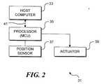
- FIGURE 2a general overview of a force feedback system 31 that includes haptic joystick 11 is illustrated.
- a host computer 33is coupled to a processor 35.
- Processor 35may comprises a microcontroller unit (MCU), as is the case in the preferred embodiment as discussed below, or may comprise a microprocessor or central processing unit with additional discrete components, such as memory, analog-to-digital converter (ADC), etc. that are included in the single integrated circuit employed for the MCU.
- MCUmicrocontroller unit
- ADCanalog-to-digital converter
- the drive signals resulting from the processor rendering the force effectsare supplied by processor 35 to an actuator 39 that generates a haptic force for transmission to the user.
- a position sensor 37is coupled to processor 35, so that signals indicating the position of the joystick control handle are provided to the processor and transmitted to the host computer.
- the host computerwill typically download force profiles (data structures and parameters) for the force effects supported by the application to processor 35. Typically, the downloading operation can be accomplished when the application is initiated.
- the processorassociates an ID number with each force effect.
- An ID numbermay represent a combination of several force effects, as explained in greater detail below. The ID number is provided by processor 35 to host computer 33.
- host computer 33When the application requests a force effect to be rendered so that the user can experience it, host computer 33 will indicate to processor 35 the ID number and any parameter modifications necessary to render the force effect identified by the ID number.
- processor 35generates the ID number for each force effect and communicate it to host computer 33 in association with specific profile data for the force effect
- the ID numbercould alternatively be pre-assigned by the host computer and communicated to the processor.
- a third alternativewould be to employ a shared algorithm executed by both host computer 33 and processor 35 so that each independently determines the same ID numbers that are assigned to all of the force effects. In any case, it is essential that each force effect be assigned an ID number that is employed in all references to the force effect communicated between processor 35 and host computer 33, so that the identifier is consistently applied.
- FIGURE 3A circuit 100, which is used in controlling haptic joystick 11, is shown in FIGURE 3.
- a power supply 12is coupled to a PWR input of a MCU 10 (which corresponds to processor 35 in FIGURE 2).
- a power switch 14is coupled to an IN2 input port of MCU 10 to enable the user to energize MCU 10 and the other associated electrical components in the haptic joystick.
- a power LED 16is coupled to an IN3 input port of MCU 10 and is illuminated whenever switch 14 is engaged.
- an optical switchhaving a transmitter (i.e., a light source) 18 and a receiver (i.e., a light sensor) 20 is provided.
- An OUT4 output port of MCU 10is coupled to transmitter 18, and an IN1 input port of the MCU is coupled to receiver 20.
- a program stored within a read-only memory (ROM - not separately shown) included within MCU 10responds to a change in the output signal from the receiver caused by the user's hand blocking the light path between the transmitter and the receiver to determine when the user is gripping the handle of the joystick.
- a Y axis DC servo motor 22 and an X axis DC servo motor 24are coupled to an OUTI output port and an OUT2 output port of MCU 10, respectively.
- a fan motor 26is coupled to an OUT3 output port of MCU 10, for cooling the components of circuit 100 to prevent overheating.
- a host computer 32is coupled to MCU 10.
- a cord(not shown in FIGURE 3) extends from haptic joystick 11 to the game port and the COM1 communication port of the host computer. It is also contemplated that the USB port of newer computers can be used for the communication path between the host computer and the MCU instead of the game port and the COM1 port.
- the game portis used by MCU 10 to transmit a digital signal indicating the orientation and/or rotational position of the joystick control handle and other status messages to an application running on host computer 32.
- the game port's button linesare employed to transmit data and clock values in a digital protocol.
- the COM1 communication portis bi-directional and is used for sending command responses from the haptic joystick to the host computer, and for transmitting commands from the host computer to the joystick. For example, a force effect command is provided by host computer 32 to MCU 10 through the COMI communication port.
- the COMI communication portinitially employs the Musical Instrument Digital Interface (MIDI) protocol to communicate with host computer 32.
- MIDIMusical Instrument Digital Interface
- MCU 10can detect a special "dongle" signal state on the game port when it is coupled to the host computer.
- the special stateindicates to MCU 10 that a serial interface protocol instead of the MIDI protocol should be employed by the COMI communication port for transmitting data to the host computer.
- MCU 10automatically switches the functionality of the COMI port to that of a standard serial interface protocol, such as RS-232.
- a standard serial interface protocolsuch as RS-232.
- the serially configured COMI communication portwill perform substantially the same functions as provided by the MIDI protocol.
- the serial interface protocolwill transmit data bidirectionally through the COM1 communication port at a rate of at least 38.4 kilobits per second. In this way, the user can enjoy the haptic joystick with operating systems or sound cards that may not support the MIDI protocol in a manner necessary for proper operation of the present invention.
- a force effectis typically scheduled and rendered in accord with machine instructions (a software program) executed by MCU 10. This program is stored in the ROM within the MCU. Effect data and other variables are loaded into random access memory (RAM), which is also included within the MCU.
- a force effectis rendered when the equation or other data defining the parameters of the force effect are applied to generating a drive signal that is applied to drive Y-axis DC servo motor 22 and/or X axis DC servo motor 24, causing the motor(s) to produce a corresponding force that is applied to the control handle of the haptic joystick. The rendered effect is thereby experienced by a user of the joystick as a force that acts on the user's hand, through the control handle.
- An X-axis position LED 34 and a Y-axis position LED 36are respectively coupled to an OUTS output port and an OUT6 output port of MCU 10. Further, a throttle LED 40 is coupled to an OUT7 output port of MCU 10.
- the light emitted by the X-axis position, Y-axis position, and throttle LEDsare time multiplexed and are incident upon a surface of a quad position detector 40.
- the position detectorresponds to the light received from each of these LEDs in four quadrants, producing sensor position signals that are multiplexed and applied to the IN4 input port of MCU 10.
- the program executed by MCU 10uses the multiplexed position signals to determine the exact disposition of the joystick handle and the throttle. Significantly, the program determines the X-axis, Y-axis, and rotational positions of the joystick handle using only two LEDs.
- haptic joystick 11employs the X-axis and Y-axis DC servo motors to apply a centering force to the control handle.
- Quad detector 40senses the position of the control handle and its displacement relative to the centered position.
- MCU 10then provides the drive signal to the two DC servo motors to center the control handle.
- the force applied by the DC servo motorsmay displace the control handle from the centered position.
- any displacement of the control handle from the centered position by the userwill cause the MCU to command the DC server motor(s) to provide a force acting on the control handle for one or both of the axes along which the displacement occurred, and this force will tend to restore the control handle to the centered position.
- moving the control handle away from center positionwill typically result in a force being applied that tends to oppose the movement until the control handle is again centered.
- the restoring forcecan be the result of rendering a force effect and thus may appear as a conventional spring force, a non-linear positive or negative force, or a more complex force.
- thirteen switches/push buttonsare respectively coupled to IN5 through IN17 input ports of MCU 10.
- the switchesare configured as follows: (a) a trigger switch disposed on the joystick's handle, i.e., to trigger 15 in FIGURE 1; (b) three switohes mounted on the joystick's control handle; (c) five push button switches 19 disposed on base 17 of the joystick, one of which functions as a shift key; and (d) four switches that comprise hat switch 21, which is also disposed on the joystick's control handle.
- MCU 10is a 25 megahertz, 16-bit microcontroller that includes 48 kilobytes of ROM, 2 kilobytes of RAM, eight analog-to-digital (A-D) converter input ports, and a plurality of digital input and output ports.
- the A-D converter portsare used for determining the position of the control handle, sensing the power provided by the power supply, providing a dead man switch, and for centering and calibrating the position of the control handle.
- the signals produced at the OUT1 and OUT2 output portsare pulse width modulated (PWM), so that MCU 10 exercises extremely accurate control of the force generated by X axis DC servo motor 22 and Y axis DC servo motor 24.
- PWMpulse width modulated
- An important aspect of the present inventionis the technique used for controlling the rendering of force effects transmitted through the control handle to the user.
- the present inventionuses a scheduler implemented in software by MCU 10 to control the rendering of force effects.
- the logical steps implemented by the scheduler for ordering and timing force effects that are transmitted to the userare shown in FIGURE 4. Beginning at a start block, the logic advances to a block 102 in which the current value of a servo clock is fetched.
- MCU 10includes a time base that is used for all timing functions. In the present invention, the time base is employed to determine a tick of the servo clock when rendering force effects. Also, the current servo clock value is initially stored when MCU 10 is energized.
- the logicadvances to a block 108 to determine velocity values for the control handle based upon changes in the stored position values relative to the values that were stored two milliseconds earlier.
- the stored position values and velocity valuesare filtered to reduce errors induced by noise. Further, the filtered velocity values are employed to determine acceleration values for the control handle, which are stored, by determining the changes in the velocity of the control handle relative to the previous velocity values that were determined two milliseconds earlier.
- the logicadvances to a block 110 and the status of the push buttons and the miscellaneous switches associated with the joystick are updated for a button list that employs an activity table to indicate the push buttons and the switches that are currently actuated.
- the logicmoves to a block 112, and a data packet is built for transmission to the host computer.
- the data packetcontains the position values that were just stored and the status of the push buttons and switches and is built following each servo clock tick, even if the host computer does not request MCU 10 to provide the data packet.
- the logicmoves to a block 114 and the status of the interlock (dead man optical switch) is stored. The interlock status depends upon whether the optical path between transmitter 18 and receiver 20 is blocked.
- the logic steps to a block 116 and queued host computer commands and device responsesare parsed. Block 116 is presented in greater detail in the discussion of FIGURES 5A and 5B below.
- the logicthen advances to a block 118, in which any force effect that is associated with an actuated push button or switch on the button list is rendered and the force effects resulting from the rendering are summed.
- a feedback force effect associated with the cannon in a button listwill be rendered so that the resulting force may be applied to the control handle.
- the logicadvances to a block 120 in which any force effects on the play list that are scheduled for the current servo clock tick are rendered and summed.
- the parsing step implemented in block 118is presented in greater detail.
- the logicadvances to a decision block 126, and a determination is made as to whether a command queue for receiving commands from the host computer is empty.
- the command queuehas a circular first in first out (FIFO) data structure.
- the command queueis eight bytes in length and is emptied at every servo clock tick (every 2 milliseconds). If the determination at decision block 126 is true, the logic jumps out of the parsing routine and returns to the main logic flow of FIGURE 4. If the command queue is not empty, the logic advances to a block 128, and the first data item (byte) in the command queue is moved into the command buffer.
- the command buffercan hold up to 128 bytes of data items, so that extremely complex commands can be passed from host computer 32 to MCU 10.
- most host commandsare relatively short in length.
- a command to create a sine wave force effectmay consume as much as 30 bytes in the command buffer
- another command to modify or execute a sine wave force effect that has already been downloadedmay requires as few as three bytes.
- the force effect profilese.g., the data structures and parameters that define the force effects not stored in ROM
- the commands between the host computer and the processor to control rendering of the force effectsare usually provided in one servo clock tick.
- the command buffer write pointeris incremented.
- Each commandhas a pair of read and write pointers for the command buffer.
- the write command buffer pointeris incremented each time a data item is written to the command buffer.
- the read command buffer pointeris incremented as each data item is read out of the command buffer for execution. In this way, when the values of the read and write pointers are equal to each other and greater than zero, a check is provided to ensure that a command that was written into the command buffer was also successfully read out of the buffer.
- the logicmoves to a decision block 136, in which a determination is made as to whether the command is being transmitted through the MIDI channel that has been assigned for communicating data between the host computer and the joystick. This determination serves to filter out MIDI commands, such as music synthesizer commands, that are not intended for MCU 10. If the determination at decision block 136 is false, the logic moves to a block 138 in which the read and write pointers for the command buffer are set to zero. Next, in a block 124, the new command flag is set to false. The logic again flows to decision block 126 so that the program may determine whether any commands remain in the host command queue.
- the programadvances to a block 140 as shown in FIGURE 5B.
- the sanity of the commandis checked by comparing the command op code in the first byte of the command with a lookup table of valid commands for the joystick.
- the logicmoves to a decision block 142, and a determination is made as to whether the command op code of the new command was found in the look up table of valid commands. If not, the logic moves to a block 148, and a negative acknowledgment (NACK) response is placed in the device (joystick) response queue, which is immediately transmitted to host computer 32.
- the logicjumps to a block 124, as shown in FIGURE 5A. In block 124, the new command flag is set to false.
- the logic steps to block 126 and the logic flowstarts over, as previously explained in regard to FIGURE 5A.
- the logicadvances to a block 144.
- the sanity of the data in the commandis evaluated by performing a check sum on the command and determining if the correct number of bytes for the command are present in the command buffer.
- the logicdetermines whether the command is sane, i.e., whether the command passed both of the data sanity checks. If not, the logic moves to a block 148, and a NACK response is placed in the device response queue for transmission to host computer 32. If the determination is true, the logic advances to a block 150, which provides that the command in the command buffer is executed. As each data item in the command buffer is executed, the read command buffer pointer is incremented.
- the logicmoves to a decision block 151 to determine whether the command failed to execute.
- the values of the read and write command buffer pointersare compared to determine whether the correct number of bytes were read from the command buffer during execution of the command. If the pointers do not have the same value, the logic moves to block 148, and a NACK response is placed in the device response queue for transmission to host computer 32. However, if the read and write command buffer pointers have the same value, the logic moves to a block 152, and a positive acknowledgment (ACK) response is placed in the device response queue. Once the ACK response is transmitted to host computer 32, the logic jumps to block 124 (in FIGURE 5A). The new command flag is set to false and the logic flows to decision block 126 so that the logical steps of method 100 can begin anew.
- ACKpositive acknowledgment
- the ACK and NACK responses in the device response queueare sent to the host computer on the same MIDI channel on which the commands are received by MCU 10 for the host command queue. Since the device response queue is just large enough (8 bytes) to contain slightly more than two ACK/NACK responses (6 bytes) at a time, the responses are sent to the host computer after each data item is determined by the MCU.
- the MIDI protocolis capable of transmitting 6.25 bytes of data to the host computer every two milliseconds (servo clock tick). Also, the size of commands, ACK/NACK responses and diagnostic messages are at least three bytes long. Consequently, no more than two responses are queued in the device response queue per servo tick, and the small size of the device response queue does not create an overflow problem. In contrast, each game port data packet built for the host, which contains the position values and the button/switch status values, is only transmitted by the MCU to the host computer upon request.
- a watchdog timeris employed to determine if the rendering of a force effect by the haptic joystick has exceeded a predetermined length of time (forty milliseconds in the preferred embodiment). If the execution of a command is determined to consume more time than forty milliseconds, it is likely that the rendering and generation of the force effect has failed, and the logic will immediately interrupt the execution of the program and reset the processor contained within MCU 10 so that the logic flow may again start implementing the steps of the scheduler.
- a plurality of commandsare executed by the program represented by the logic in FIGURES 4, 5A, and 5B, and an exemplary partial list of the valid commands is provided in Table 1, below.
- Command Set Effect Playback UtilityEffect Manipulation Manufacturing PutForce Play Effect Change MIDI channel Destroy Effect Force Query Constant Stop Effect Effect Play Status Set Effect Parameter , Test Spring Button Play Reset All Index Debug Bumper Reset Forces On Modify Effect Damper Reset Forces Off Parameter Friction Shutdown Inertia Wavetable Romtable Synth Delay Process
- the command set provided in Table 1 aboveclearly illustrates at least five different types of commands: effect, playback, utility, effect manipulation, and manufacturing.
- the diverse command setenables the present invention to implement a wide variety of force effects and system procedures that are transmitted by host computer 32 to MCU 10.
- the schedulerwhich is implemented in software executed by MCU 10, is primarily responsible for enabling the haptic joystick to render force effects that are requested by the host computer.
- the schedulerhas a round robin queue for executing a play list that orders the playback of force effects.
- Behavior force effectshave force profiles that employ the position, velocity, and/or acceleration values to generate a force effect. These values are determined by MCU 10 in response to the movement of the control handle by the user.
- friction, damping, inertia, springs, and constant forcesare all behavioral effects that are produced in response to the user moving the control handle of the haptic joystick.
- behavior effectsare particularly well suited to simulating force effects that are associated with movement of a virtual object within a virtual world.
- Synthesized effectsare rendered by MCU 10 as a function of mathematical formulas that are time variant.
- the synthesized effect formulasinclude polynomials, transform coefficients, sine, cosine, and triangular wave forms.
- the parameters that are modifiable by the host computer for a synthesized effectinclude direction, frequency, and envelope (a time varying amplitude of the force effect).
- Wave table force effectsare rendered by MCU 10 based on arbitrary profiles that are stored in a table within the RAM or ROM of the MCU. These force effects are similar to synthesized effects and differ only in the manner that the force data is obtained for a given servo tick. Although any wave table force effects downloaded from the host computer are stored in RAM, predefined wave table force effects are stored in ROM within MCU 10. Since a push button or a switch are capable of being mapped to any class of force effect, they may even be mapped to a wave table effect stored in either RAM or ROM.
- a partial list of wave table force effects stored in ROM, ROM ID numbers assigned to each, and the parameters (output rate, gain, and duration) applicable to eachare provided in Table 2 below.
- variable parameterincludes combinations of the behavior, synthesized, and wave table force effects discussed above.
- the parameters of the combined force effectscan be variables that change over time, as a function of a mathematical formula or according to the disposition of the joystick's control handle.
- variable parameter force effectsinclude use of a sine wave to modulate the amplitude of a spring, and a wave table effect that becomes stronger as the velocity with which the joystick control handle is moved increases. It is highly desirable to enable the parameters of a force effect being rendered to be varied by the MCU instead of the host computer. If the host computer were required to vary the parameter in real time and provide continuous updates to the processor, the task would significantly increase the computational load on the host computer.
- the schedulersuperimposes every force effect on the play list that is scheduled for the current servo clock tick, so that the MCU only renders the total of those force effects for the current tick. If a switch or push button associated with a force effect is actuated by the user, the ID number for that force effect will be entered on the play list and rendered by the MCU. Further, the time interval during which a force effect is applied will normally equal the time during which the switch/push button remains actuated.
- Process list force effectsare based on process lists that provide for the rendering of combinations of the first four force effect classes, i.e., behavior, synthesized, variable parameter, and wave table force effects.
- superimposed process listsimplement each force effect on the list according to the lifetime parameters of each force effect. In this way, force effects on the list may stop and start at different times so that the superimposition of all of the force effects on the list will only occur for that portion of the overall lifetime of the process list when all of the listed force effects are being generated. Any force effect included on the process list may terminate once the duration of the force effect specified in its parameters is completed and the other force effects can continue being generated.
- a sequential process listprovides for rendering and generating of the force effects included in the list sequentially, so that each successive force effect is generated only after the preceding force effect is completed. Significantly, each force effect retains the amplitude envelope specified in its parameters.
- a sequential process listalways implements each force effect separately, until the specified duration of the force effect is complete. Only then will the next force effect on the sequential process list be rendered by the MCU and generated.
- a concatenated process listis similar to a sequential process list because the force effects on the list are individually rendered and generated in the sequence in which they appear on the list. However, the concatenated process list also invokes an overall amplitude envelope that supersedes the individually defined amplitude envelopes of the force effects that are included on the list. Thus, the individual force effects in a concatenated process list are implemented sequentially under an overall amplitude envelope that may significantly modify the amplitudes indicated in the profile parameter for each force effect.
- process listscan contain a nested reference to another process list. In this way, a plurality of process lists may be nested to create extremely complex force effects for rendering and generation.
- Process listsare similar to subroutine calls because they permit a complex combination of force effects to be invoked with a single command (ID number) that is assigned to the combination.
- ID numbera single command
- a process list active on the play listis implemented by the scheduler at every increment (tick) of the servo clock, the process list employs its own process list clock to time out individual force effects on the process list after they have been rendered and generated.
- a play list that is implemented by the schedulercan perhaps best be understood as a special case of a superimposed process list.
- the play listis a chronological ordering of all of the force effect IDs that have been indicated by the host computer for each tick of the servo clock. Since the play list is completely traversed for each servo clock tick, the actual force effect rendered by the MCU at a tick is the summation of all effects on the play list that are indicated for that time. Further, each force effect has an associated lifetime, and the time remaining for a force effect is computed for each traverse of the play list. Although force effects remain stored within the memory of the MCU for later use, the force effects originally on the play list that have timed out are marked inactive and removed from the list.
- the host computermay modify a parameter of a force effect being generated, in real time, by sending a command to the MCU that includes a new parameter and the ID number for the force effect.
- force effectsare not modified in mid-rendering by the MCU; instead, modifications in rendering are synchronously performed in the host command parsing routine.
- force effectscan be started and stopped when the host computer indicates the ID number of the force effect and the desired action. Whenever a force effect that was stopped is restarted before its lifetime counter has timed out, its lifetime counter will be restarted with the initial value stored before the interruption occurred.
- the button listincludes the status of actuated switches and push buttons and is maintained by the MCU separately from the play list.
- the button listcontains ID numbers for force effects that are mapped to specific push buttons or switches in a one-to-one correspondence.
- a plurality of ID numbers corresponding to multiple force effectscan also be mapped to a single switch or a push button.
- the host computermay indicate the mapping of the switches and push buttons or enable the user to selectively map desired force effects to particular push buttons or switches.
- the MCUdetects that a push button or switch mapped to a force effect is engaged, the force effect is added to the play list and remains there until the push button or switch is disengaged.
- mapped effectsare added to and removed from the play list whenever a change in the state (engaged/disengaged) of a push button or a switch occurs.
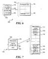
- a specific data structure 154 applied to a force effect objectincludes the force effect class in a block 156, a lifetime value in a block 160 and a data pointer 158.
- Block 156is employed to indicate the class of the force effect, i.e., behavior, wave table, synthesized, or variable parameter.
- Data pointer 158indicates an address in memory of a data structure 162 used for storing the parameters of a specific force effect, and data structure 162 includes a first parameter in a block 164 through an n,h parameter in a block 166.
- An ID numberis assigned to force effect object 168 when data structure 154 and data structure 162 are employed to create the force profile of a particular class of force effect.
- the host computerSince the host computer employs the ID number to indicate a specific force effect for rendering by MCU 10, the host computer does not have to allocate the actual memory for storing an identification of the two data structures to indicate a specific force effect. Instead, MCU 10 has the task of translating an ID number for a force effect into corresponding storage locations for the data structures that apply to the force effect so that the force effect can be rendered. In this way, the computational overhead required of the host computer for indicating the rendering of force effects is dramatically reduced. Also, host computer 32 can update the values for the parameters contained within data structure 162 simply by sending a command that specifies the ID number for the relevant force effect and provides new value(s) for its parameters.
- MCU 10has predetermined storage locations in RAM for sixteen force effect profiles and sixteen ID numbers.
- the force effect profiles downloaded from host computer 32 to MCU 10are provided in a particular order, so that the amount of RAM allocated by the MCU for storing force effect profiles may be conserved.
- Host computer 32first provides the force effect profiles for all of the non-process list force effects to MCU 10, and the host computer receives the ID numbers assigned to each force effect after the profile is downloaded to the MCU.
- host computer 32employs the ID numbers provided by MCU 10 to identify the force effect profiles for any process list force effect that is downloaded to the MCU.
- An alternative embodiment of the present inventioncould provide for dynamically scaling the amount of RAM allocated for force effect profiles to match the number and type of force effect profiles downloaded by the host computer.
- Process listsare a special case of a force effect object, because the lifetime value required for a force effect object is not applicable to a process list object.
- process list object 169employs a general data structure 188 that identifies the class as a process in a block 190 and a data pointer 192, the lifetime value in a block 194 is thus not included. Instead, the lifetime of the process list object is determined by the values contained within a specific data structure 170 at the memory address indicated by data pointer 192.
- an ID numbermay be associated with process list object 169 so that host computer 32 can indicate the process list to the MCU in the same manner as if it were a force effect object representing a single effect.
- Data structure 170includes the process type in a block 172, a plurality of effect indices, including an effect index 1 in a block 174 through an effect index n in a block 182, their associated lifetime values in blocks 176 and 184.
- the default values for the lifetimesare the values that were initially downloaded for the individual effect data structures. However, the lifetime values may be modified by the host computer from the default values.
- the process type in block 172indicates how the effects identified by the list are to be rendered by the processor e.g., superimposed, concatenated, or sequential.
- An end of list flag 186signifies that all of the effects indexed by the process list have been identified.
- General data structure 188includes block 190, which identifies the class as a process list object.
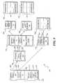
- Data pointer 192indicates the memory address of a specific data structure 170' for the process list object, and a block 172' indicates that the process list object is sequential.
- the effect index 1 in a block 174'indicates another specific data structure 154', and a block 156' of the specific structure specifies that the force effect class is a wave table.
- a lifetime value (75) in a block 160'is associated with data structure 154'
- a force effect lifetime in a block 176'determines the actual duration (lifetime) of the wave table effect on the process list.
- the process list lifetime valueis 75 servo clock ticks, which is the same as the lifetime value of the wave table effect.
- the value of the force effect lifetime in block 176'would supersede the value of the lifetime in block 160' in determining the length of time on the process list that the wave table force effect will be produced.
- Specific data structure 154'also includes a data pointer 158' that indicates a data structure 162' for storing the parameters of the wave table force effect.
- Data structure 162'begins with a parameter 1 in a block 164' and concludes with a parameter n in a block 166'.
- a force effect index 2 in a block 178'points to another specific data structure 154", and a block 156" defines the force effect class to be a spring.
- a lifetime value (60)is indicated in a block 160" of data structure 154
- a force effect lifetime value in a block 180'determines the actual duration (lifetime) of the spring effect on the process list.
- the process list lifetimeis set at 50 servo clock ticks in block 180'.
- the force effect lifetime in block 180'will supersede the lifetime value (60) indicated by block 160", thereby shortening the actual duration of the spring effect on the process list.
- End of list flag 186'indicates that the process list has been traversed, and that there are no more force effects on the list for rendering by the processor.
- the wave table force effect and the spring force effectwill be rendered sequentially for 75 and 50 servo clock ticks (125 total ticks), respectively. It is envisioned that a plurality of force effect objects may be implemented by a process list that includes another nested process list simply by referencing the ID number assigned to the initial process list.
- a general data structure 214 of the play list objectincludes a plurality of force effect indices and force effect times.
- the data structure of a play list objectis similar to that of a process list object, except that the play list object does not include a process type. Instead, play list object 200 includes a list of superimposed force effects.
- the play list (object)is traversed for each increment (tick) of the servo clock, and every force effect scheduled for a particular tick is rendered and summed. Starting with a force effect index 1 in a block 202 and finishing with a force effect index n in a block 210, each force effect that is scheduled for the current servo clock tick is identified.
- the values of the force effect times in a block 204 through a force effect time n in a block 212are employed to determine the scheduling of the corresponding force effect indices.
- a force effect timeincludes a lifetime value for the force effect and may also include a start time.
- An end of list flag 216is employed to determine when the play list has been completely traversed for each tick of the servo clock. All of the force effects determined for the current tick of the servo clock are accumulated, so that MCU 10 only renders the total of the force effects for the current tick.
- Force effect index 1 in block 202points to general data structure 188 for a process list, and the value of the first force effect time (200) in a block 204 is employed to determine the actual lifetime or duration of the process list defined by data structure 188, on the play list.
- the value of the first force effect time on the play listmay be less than or greater than the total time of the force effect lifetimes on the process list.
- the play list force effect timesupersedes the total amount of time indicated by the process list to render the force effect. Since the play list first force effect lifetime value (200) exceeds the lifetime of the indexed process list force effect (125), the process list will loop until the play list lifetime value expires.
- a force effect index 2 in a block 206points to a specific data structure 154"' for a synthesized force effect.
- a data pointer 158"'points to a data structure 162"' that includes the parameters for the synthesized force effect.
- the actual amount of time that the synthesized force effect is appliedis determined by the value (50) in a block 208; this time always supersedes the value (60) of a lifetime value in a block 160"', if they differ.
- general data structure 214is completely traversed by the scheduler for each tick of the servo clock, so that the force effect rendered by MCU 10 is generated as an accumulation of every force effect scheduled for the current tick of the servo clock.
Landscapes
- Engineering & Computer Science (AREA)
- General Engineering & Computer Science (AREA)
- Multimedia (AREA)
- Theoretical Computer Science (AREA)
- Human Computer Interaction (AREA)
- Physics & Mathematics (AREA)
- General Physics & Mathematics (AREA)
- Position Input By Displaying (AREA)
- User Interface Of Digital Computer (AREA)
- Materials For Medical Uses (AREA)
- Ropes Or Cables (AREA)
- Laying Of Electric Cables Or Lines Outside (AREA)
- Pharmaceuticals Containing Other Organic And Inorganic Compounds (AREA)
- Medicines Containing Material From Animals Or Micro-Organisms (AREA)
Abstract
Description
| Command Set | ||||
| Effect | Playback | Utility | Effect Manipulation | Manufacturing |
| PutForce | Play Effect | Change MIDI channel | Destroy Effect | Force Query |
| Constant | Stop Effect | Effect Play Status | Set Effect Parameter , | Test |
| Spring | Button Play | Reset All | Index | Debug |
| Bumper | Reset Forces On | Modify Effect | ||
| Damper | Reset Forces Off | Parameter | ||
| Friction | Shutdown | |||
| Inertia | ||||
| Wavetable | ||||
| Romtable | ||||
| Synth | ||||
| Delay | ||||
| Process |
| ROM Table Force Effects | ||||
| Name | ROM ID | Output Rate | Gain | |
| Random Noise | ||||
| 1 | Any | Any | 12289 | |
| Aircraft Carrier Take Off | 2 | 100 | 100 | 2625 |
| Basketball Dribble | 3 | 100 | 50 | 166 |
| Car Engine Idling | 4 | 100 | 14 | 10000 |
| Chainsaw | 5 | 100 | 30 | 1000 |
| Chainsawing Things | 6 | 100 | 100 | 1000 |
| Diesel Engine Idling | 7 | 100 | 40 | 10000 |
| Jump | 8 | 100 | 100 | 348 |
| Land | 9 | 100 | 100 | 250 |
| 10 | 200 | 100 | 1000 | |
| Punched | 11 | 100 | 100 | 83 |
| 12 | 100 | 100 | 1000 | |
| 13 | 100 | 98 | 500 | |
| 14 | 100 | 66 | 25 | |
| 15 | 100 | 75 | 500 | |
| 16 | 100 | 100 | 2500 | |
| 17 | 100 | 100 | 50 | |
| 18 | 100 | 100 | 295 | |
| 19 | 500 | 95 | 1000 | |
| 20 | 500 | 96 | 1000 | |
| 21 | 500 | 100 | 1000 | |
| 22 | 500 | 100 | 1000 | |
| Laser 3 | 23 | 500 | 100 | 1000 |
| 24 | 500 | 70 | 1000 | |
| Out Of Ammo | 25 | 100 | 100 | 25 |
| 26 | 100 | 71 | 1000 | |
| Missile | 27 | 100 | 100 | 250 |
| 28 | 100 | 100 | 1000 | |
| Short Plasma | 29 | 500 | 97 | 250 |
| 30 | 500 | 100 | 500 | |
| 31 | 500 | 99 | 625 | |
| 32 | 100 | 100 | 440 | |
| 33 | 100 | 68 | 1000 | |
| 34 | 100 | 100 | 75 | |
| 35 | 500 | 100 | 31 | |
| 36 | Any | Any | 1000 | |
| 37 | Any | Any | 1000 |
Claims (57)
- A force feedback device that is responsive to a request from a hostcomputer to generate scheduled force effects, comprising:(a) a member adapted to be grasped by a user of the force feedbackdevice;(b) a prime mover coupled to the member, said prime moverproducing a force that acts on the member;(c) a processor coupled to the prime mover, said processor rendering theforce effect to produce a drive signal that is coupled to the prime mover, causing theprime mover to generate a force corresponding to the force effects; and(d) a scheduler implemented by the processor, said schedulerscheduling the force effects so that they are generated during time intervalsrequested by the host computer;(e) a communication link coupling the host computer to the processor,said communication link conveying the request to render the force effects fromthe host computer to the processor, for scheduling the force effects.
- The force feedback device of Claim 1, wherein the schedulerestablishes an order of execution for the force effects in response to commandsreceived from the host computer in the request.
- The force feedback device of Claim 1, wherein the schedulerestablishes a start time and a stop time for each force effect generated in responseto commands received from the host computer.
- The force feedback device of Claim 1, further comprising a servoclock that is employed to determine a duration for each of the time intervals, saidscheduler responding to the servo clock to control the duration of a force effect.
- The force feedback device of Claim 1, wherein a plurality of theforce effects are executed concurrently, causing a superimposition of saidplurality of the force effects.
- The force feedback device of Claim 1, wherein one force effectcomprises a plurality of other force effects.
- The force feedback device of Claim 1, further comprising amemory in which a profile of a force effect initially received from the hostcomputer and an identifier that is assigned to said profile are stored, saidscheduler receiving the unique identifier for each force effect requested by thehost computer for use in scheduling the force effects.
- The force feedback device of Claim 7, wherein the schedulerreceives the unique identifier and a modification of a parameter of the profile thatwas stored from the host computer, said processor employing the modification ofthe parameter when rendering the force effect.
- The force feedback device of Claim 7, wherein the processorreceives a plurality of force effect profiles from the host computer that arecombined into a single force effect by the scheduler, said single force effect beingassigned a unique identifier.
- The force feedback device of Claim 1, further comprising amemory that stores a table of predefined force effect profiles, each of said profilesbeing assigned a unique identifier, said unique identifiers being used by thescheduler in identifying each predefined force effect that is included in thescheduled force effects to be generated.
- The force feedback device of Claim 1, wherein each force effectbelongs to one of a plurality of different classes, said plurality of different classesincluding: a behavior class, a wave table class, a synthesized class, a variableparameter class, and a process list class.
- The force feedback device of Claim 1, further comprising a switchthat is coupled to the processor, said scheduler mapping a force effect to the switchso that said force effect is rendered by the processor when the switch is actuated.
- The force feedback device of Claim 12, wherein the processorreceives a request from the host computer indicating said force effect that ismapped to the switch.
- The force feedback device of Claim 12, wherein the schedulerimmediately causes the force effect mapped to the switch to be rendered andgenerated when the switch is actuated and stops said force effect from beinggenerated when the switch is no longer actuated.
- The force feedback device of Claim 1, wherein the communicationlink comprises a game port and a musical instrument digital interface port.
- The force feedback device of Claim 1, wherein the communicationlink comprises a universal serial bus port.
- The force feedback device of Claim 1, wherein the communicationlink comprises a game port and a serial port.
- The force feedback device of Claim 1, further comprising aplurality of prime movers coupled to the member, at least one of said plurality ofprime movers acting on the member to produce each force effect.
- The force feedback device of Claim 1, further comprising a sensor,said sensor producing a signal indicative of whether the user is gripping themember, said processor being coupled to the sensor and responding to the signalby preventing the prime mover from producing any force effect when the user isnot gripping the member.
- The force feedback device of Claim 1, wherein a superimposedforce effect comprising multiple force effects that are executed simultaneously isamong the plurality of scheduled force effects controlled by the scheduler.
- The force feedback device of Claim 1, wherein a sequential forceeffect comprising multiple force effects that are executed sequentially is amongthe plurality of scheduled effects controlled by the scheduler.
- The force feedback device of Claim 1, wherein a concatenatedforce effect comprising multiple force effects that are executed sequentially andhave a predetermined envelope is among the plurality of scheduled effectscontrolled by the scheduler, said envelope controlling an amplitude of saidmultiple force effects that are executed sequentially.
- A force feedback device that generates force effects in accord witha schedule, comprising:(a) a force generator that responds to a drive signal by producing aforce that acts on a member, said member transmitting the force to a user incontact with the member so that the user experiences a force effect;(b) a sensor that detects a position of the member and produces asignal indicative of the position, said signal being used in defining at least one ofthe force effects;(c) a memory for storing data that specify the force effects; and(d) a processor, coupled to the force generator, the sensor, and thememory, said processor executing machine instructions that are stored in the memoryand carrying out a plurality of functions defined by said machine instructions,including determining when each force effect is initiated and a duration of each forceeffect in accord with the schedule, said processor rendering each force effect asspecified by the data stored in the memory, and when a force effect is required by theschedule, providing a corresponding drive signal to the force generator.
- The force feedback device of Claim 23, wherein an order in whichthe force effects are executed is defined in the schedule.
- The force feedback device of Claim 23, wherein a relative starttime and a duration of each of the force effects are specified in the schedule.
- The force feedback device of Claim 23, further comprising a servoclock that is employed by the processor to determine a time interval forcompleting the plurality of force effects defined by the schedule, said processorterminating any force effect being produced at an end of said time interval.
- The force feedback device of Claim 23, wherein the scheduleprovides for superimposing multiple force effects.
- The force feedback device of Claim 23, wherein a force effectincluded on the schedule comprises a combination of other force effects.
- The force feedback device of Claim 23, wherein the processorstores profiles for the plurality of force effects in the memory and assigns uniqueidentifiers to the plurality of force effects, each unique identifier being associatedwith a profile for a different one of the plurality of force effects, the processorrendering a force effect that is specified in the schedule by the unique identifierfor said force effect, in accord with the profile for said force effect.
- The force feedback device of Claim 29, wherein a change in aparameter of a profile is stored in the memory by the processor to alter a force effect.
- The force feedback device of Claim 29, wherein a plurality of profilesare combined to indicate a single force effect that is assigned a unique identifier.
- The force feedback device of Claim 23, wherein a plurality ofprofiles are predefined in the memory.
- The force feedback device of Claim 23, wherein each of the forceeffects is characterized as one of a plurality of different classes, said plurality ofdifferent classes including: a behavior class, a wave table class, a synthesizedclass, a variable parameter class, and a process list class.
- The force feedback device of Claim 23, further comprising aswitch that is coupled to the processor, a force effect being mapped to the switchand rendered by the processor when the switch is actuated.
- The force feedback device of Claim 23, further comprising a pluralityof force generators coupled to the member, at least one of said plurality of forcegenerators acting on the member to produce each of the plurality of force effects.
- The force feedback device of Claim 23, further comprising asensor, said sensor producing a signal indicative of whether the user is grippingthe member, said processor being coupled to the sensor and responding to thesignal by preventing the force generator from producing any force when the useris not gripping the member.
- The force feedback device of Claim 23, wherein a superimposedforce effect comprising multiple force effects that are executed simultaneously isamong the plurality of force effects included on the schedule.
- The force feedback device of Claim 23, wherein a sequential forceeffect comprising multiple force effects that are executed sequentially is amongthe plurality of force effects included on the schedule.
- The force feedback device of Claim 23, wherein a concatenatedforce effect comprising multiple force effects that are executed sequentially andhave a predetermined envelope is among the force effects included on theschedule, said envelope controlling an amplitude of said multiple of force effectsthat are executed sequentially.
- A method for controlling a device that generates force effects,comprising the steps of:(a) storing data that define the force effects in a memory of the device;(b) creating a schedule of force effects that defines when each force effectthat is included on the schedule should be initiated and a duration of each force effect;(c) as a function of the schedule, providing a drive signal that enablesa force corresponding to the force effect to be produced by the device, so that theforce effects are generated in accord with the schedule.
- The method of Claim 40, wherein the step of creating the scheduleincludes the step of specifying an order in which the force effects are to beproduced, to define the schedule.
- The method of Claim 40, wherein the step of creating the scheduleincludes the step of indicating a start time and duration for each force effect, todefine the schedule.
- The method of Claim 40, further comprising the step ofterminating a force effect following a lapse of a predefined time interval.
- The method of Claim 40, wherein the schedule specifies multipleforce effects that are superimposed.
- The method of Claim 40, wherein a force effect specified by theschedule comprises a combination of other force effects.
- The method of Claim 40, further comprising the steps of:(a) assigning a unique identifier to each force effect; and(b) specifying each force effect included in the schedule with theunique identifier for said force effect.
- The method of Claim 46, further comprising the step of modifyinga parameter of the data that define a force effect to change the force effect.
- The method of Claim 46, wherein data specifying a plurality offorce effects are combined to specify a single force effect.
- The force feedback device of Claim 40, further comprising the steps of:(a) storing data that define predefined force effects in the memory,each of the force effects being assigned a unique identifier; and(b) in response to a request to produce one of the predefined forceeffects identified by the unique identifier, producing said force effect.
- The method of Claim 40, wherein each force effect is one of aplurality of classes, said plurality of classes including: a behavior class, a wavetable class, a synthesized class, a variable parameter class, and a process list class.
- The method of Claim 40, further comprising the steps of(a) providing a switch that is coupled to the device; and(b) mapping a force effect to the switch so that said force effect isproduced when the switch is actuated.
- The method of Claim 40, wherein at least a portion of the datadefining the force effects are transmitted to the device from a host computer towhich the device is adapted to be coupled.
- The method of Claim 40, wherein a force effect included on theschedule comprises multiple force effects that are produced simultaneously.
- The method of Claim 40, wherein a concatenated force effect includedon the schedule comprises multiple force effects that are produced sequentially, theconcatenated force effect having a pre-determined envelope, said envelope controllingan amplitude of the force effects that are produced sequentially.
- The method of Claim 40, wherein a sequential force effect includedon the schedule comprises multiple force effects that are produced sequentially.
- A force feedback device that is responsive to a request from a hostcomputer to generate a force effect, comprising:(a) a member adapted to be grasped by a user of the force feedback device;(b) a prime mover coupled to the member, said prime moverproducing a force that acts on the member;(c) a processor coupled to the prime mover, said processor renderingthe force effect to produce a drive signal that is coupled to the prime mover,causing the prime mover to generate a force corresponding to the force effect; and(d) a communication link coupling the host computer to the processor,the communication link conveying the request to render the force effect from thehost computer to the processor, said processor determining whether the processoris linked to the host computer through a musical instrument digital interface port or through a serial port and automatically configuring the communication link toemploy an appropriate one of a musical instrument digital interface protocol and aserial protocol to communicate with the host computer.
- A force feedback device, comprising:(a) a member adapted to be grasped by a user of the force feedbackdevice;(b) a prime mover coupled to the member, said prime moverproducing a force that acts on the member;(c) a sensor that detects a position of the member and produces asignal indicative of the position;(d) a processor coupled to the prime mover and to the sensor, saidprocessor responding to the signal to determine a deviation in the position of themember away from a centered position and producing a drive signal that issupplied to the prime mover to cause it to generate a restoring force that isapplied to the member, said restoring force tending to move the member to thecentered position.
Applications Claiming Priority (2)
| Application Number | Priority Date | Filing Date | Title |
|---|---|---|---|
| US845540 | 1997-04-25 | ||
| US08/845,540US6005551A (en) | 1997-04-25 | 1997-04-25 | Offline force effect rendering |
Publications (2)
| Publication Number | Publication Date |
|---|---|
| EP0875819A1true EP0875819A1 (en) | 1998-11-04 |
| EP0875819B1 EP0875819B1 (en) | 2002-10-02 |
Family
ID=25295463
Family Applications (1)
| Application Number | Title | Priority Date | Filing Date |
|---|---|---|---|
| EP98301055AExpired - LifetimeEP0875819B1 (en) | 1997-04-25 | 1998-02-13 | Offline force effect rendering |
Country Status (5)
| Country | Link |
|---|---|
| US (1) | US6005551A (en) |
| EP (1) | EP0875819B1 (en) |
| JP (1) | JP4750234B2 (en) |
| AT (1) | ATE225532T1 (en) |
| DE (1) | DE69808365T2 (en) |
Cited By (26)
| Publication number | Priority date | Publication date | Assignee | Title |
|---|---|---|---|---|
| US6067077A (en) | 1998-04-10 | 2000-05-23 | Immersion Corporation | Position sensing for force feedback devices |
| US6078308A (en)* | 1995-12-13 | 2000-06-20 | Immersion Corporation | Graphical click surfaces for force feedback applications to provide user selection using cursor interaction with a trigger position within a boundary of a graphical object |
| US6100874A (en)* | 1995-11-17 | 2000-08-08 | Immersion Corporation | Force feedback mouse interface |
| US6104382A (en) | 1997-10-31 | 2000-08-15 | Immersion Corporation | Force feedback transmission mechanisms |
| US6147674A (en)* | 1995-12-01 | 2000-11-14 | Immersion Corporation | Method and apparatus for designing force sensations in force feedback computer applications |
| US6166723A (en)* | 1995-11-17 | 2000-12-26 | Immersion Corporation | Mouse interface device providing force feedback |
| US6169540B1 (en) | 1995-12-01 | 2001-01-02 | Immersion Corporation | Method and apparatus for designing force sensations in force feedback applications |
| GB2353116A (en)* | 1999-05-05 | 2001-02-14 | Immersion Corp | Memory and force output management for a force feedback system |
| US6252579B1 (en) | 1997-08-23 | 2001-06-26 | Immersion Corporation | Interface device and method for providing enhanced cursor control with force feedback |
| US6285351B1 (en) | 1997-04-25 | 2001-09-04 | Immersion Corporation | Designing force sensations for computer applications including sounds |
| US6292170B1 (en) | 1997-04-25 | 2001-09-18 | Immersion Corporation | Designing compound force sensations for computer applications |
| US6417638B1 (en) | 1998-07-17 | 2002-07-09 | Sensable Technologies, Inc. | Force reflecting haptic interface |
| US6697044B2 (en) | 1998-09-17 | 2004-02-24 | Immersion Corporation | Haptic feedback device with button forces |
| WO2005032070A3 (en)* | 2003-09-25 | 2005-06-16 | British Telecomm | Haptics transmission systems |
| US6956558B1 (en) | 1998-03-26 | 2005-10-18 | Immersion Corporation | Rotary force feedback wheels for remote control devices |
| WO2006019389A2 (en) | 2004-07-15 | 2006-02-23 | Immersion Corporation | System and method for ordering haptic effects |
| US7027032B2 (en) | 1995-12-01 | 2006-04-11 | Immersion Corporation | Designing force sensations for force feedback computer applications |
| EP1471410A3 (en)* | 2003-04-14 | 2007-07-04 | Alps Electric Co., Ltd. | Force-feedback input device |
| EP1278152A3 (en)* | 2001-07-17 | 2008-02-27 | Alps Electric Co., Ltd. | Multifunctional input device for centralized control of plurality of regulable functions |
| US7489309B2 (en) | 1996-11-26 | 2009-02-10 | Immersion Corporation | Control knob with multiple degrees of freedom and force feedback |
| EP2955609A1 (en)* | 2014-06-09 | 2015-12-16 | Immersion Corporation | Haptic devices and methods for providing haptic effects via audio tracks |
| US9588586B2 (en) | 2014-06-09 | 2017-03-07 | Immersion Corporation | Programmable haptic devices and methods for modifying haptic strength based on perspective and/or proximity |
| EP2537086B1 (en)* | 2010-02-19 | 2017-05-17 | Analog Devices, Inc. | Method and device for detecting user input and providing a user-customizable haptic output |
| EP3417920A1 (en)* | 2013-11-14 | 2018-12-26 | Immersion Corporation | Haptic trigger control system |
| US10185396B2 (en) | 2014-11-12 | 2019-01-22 | Immersion Corporation | Haptic trigger modification system |
| US10353471B2 (en) | 2013-11-14 | 2019-07-16 | Immersion Corporation | Haptic spatialization system |
Families Citing this family (87)
| Publication number | Priority date | Publication date | Assignee | Title |
|---|---|---|---|---|
| US6433771B1 (en) | 1992-12-02 | 2002-08-13 | Cybernet Haptic Systems Corporation | Haptic device attribute control |
| US5739811A (en) | 1993-07-16 | 1998-04-14 | Immersion Human Interface Corporation | Method and apparatus for controlling human-computer interface systems providing force feedback |
| US5691898A (en) | 1995-09-27 | 1997-11-25 | Immersion Human Interface Corp. | Safe and low cost computer peripherals with force feedback for consumer applications |
| US5959613A (en) | 1995-12-01 | 1999-09-28 | Immersion Corporation | Method and apparatus for shaping force signals for a force feedback device |
| US5999168A (en) | 1995-09-27 | 1999-12-07 | Immersion Corporation | Haptic accelerator for force feedback computer peripherals |
| US6300936B1 (en)* | 1997-11-14 | 2001-10-09 | Immersion Corporation | Force feedback system including multi-tasking graphical host environment and interface device |
| US6161126A (en) | 1995-12-13 | 2000-12-12 | Immersion Corporation | Implementing force feedback over the World Wide Web and other computer networks |
| US6374255B1 (en) | 1996-05-21 | 2002-04-16 | Immersion Corporation | Haptic authoring |
| US6125385A (en) | 1996-08-01 | 2000-09-26 | Immersion Corporation | Force feedback implementation in web pages |
| US6411276B1 (en) | 1996-11-13 | 2002-06-25 | Immersion Corporation | Hybrid control of haptic feedback for host computer and interface device |
| US6020876A (en) | 1997-04-14 | 2000-02-01 | Immersion Corporation | Force feedback interface with selective disturbance filter |
| US7091948B2 (en)* | 1997-04-25 | 2006-08-15 | Immersion Corporation | Design of force sensations for haptic feedback computer interfaces |
| US6211861B1 (en) | 1998-06-23 | 2001-04-03 | Immersion Corporation | Tactile mouse device |
| US6088019A (en) | 1998-06-23 | 2000-07-11 | Immersion Corporation | Low cost force feedback device with actuator for non-primary axis |
| US8020095B2 (en)* | 1997-11-14 | 2011-09-13 | Immersion Corporation | Force feedback system including multi-tasking graphical host environment |
| US6448977B1 (en)* | 1997-11-14 | 2002-09-10 | Immersion Corporation | Textures and other spatial sensations for a relative haptic interface device |
| US6256011B1 (en) | 1997-12-03 | 2001-07-03 | Immersion Corporation | Multi-function control device with force feedback |
| US6429846B2 (en) | 1998-06-23 | 2002-08-06 | Immersion Corporation | Haptic feedback for touchpads and other touch controls |
| US6697043B1 (en) | 1999-12-21 | 2004-02-24 | Immersion Corporation | Haptic interface device and actuator assembly providing linear haptic sensations |
| US6717573B1 (en) | 1998-06-23 | 2004-04-06 | Immersion Corporation | Low-cost haptic mouse implementations |
| US6707443B2 (en) | 1998-06-23 | 2004-03-16 | Immersion Corporation | Haptic trackball device |
| US6985133B1 (en) | 1998-07-17 | 2006-01-10 | Sensable Technologies, Inc. | Force reflecting haptic interface |
| US7065633B1 (en) | 1999-01-28 | 2006-06-20 | Ati International Srl | System for delivering exception raised in first architecture to operating system coded in second architecture in dual architecture CPU |
| US7941647B2 (en) | 1999-01-28 | 2011-05-10 | Ati Technologies Ulc | Computer for executing two instruction sets and adds a macroinstruction end marker for performing iterations after loop termination |
| US6978462B1 (en) | 1999-01-28 | 2005-12-20 | Ati International Srl | Profiling execution of a sequence of events occuring during a profiled execution interval that matches time-independent selection criteria of events to be profiled |
| US6763452B1 (en) | 1999-01-28 | 2004-07-13 | Ati International Srl | Modifying program execution based on profiling |
| US8127121B2 (en) | 1999-01-28 | 2012-02-28 | Ati Technologies Ulc | Apparatus for executing programs for a first computer architechture on a computer of a second architechture |
| US7013456B1 (en) | 1999-01-28 | 2006-03-14 | Ati International Srl | Profiling execution of computer programs |
| US8074055B1 (en) | 1999-01-28 | 2011-12-06 | Ati Technologies Ulc | Altering data storage conventions of a processor when execution flows from first architecture code to second architecture code |
| US8121828B2 (en) | 1999-01-28 | 2012-02-21 | Ati Technologies Ulc | Detecting conditions for transfer of execution from one computer instruction stream to another and executing transfer on satisfaction of the conditions |
| US7275246B1 (en) | 1999-01-28 | 2007-09-25 | Ati International Srl | Executing programs for a first computer architecture on a computer of a second architecture |
| US7111290B1 (en) | 1999-01-28 | 2006-09-19 | Ati International Srl | Profiling program execution to identify frequently-executed portions and to assist binary translation |
| US6954923B1 (en) | 1999-01-28 | 2005-10-11 | Ati International Srl | Recording classification of instructions executed by a computer |
| US6424356B2 (en) | 1999-05-05 | 2002-07-23 | Immersion Corporation | Command of force sensations in a forceback system using force effect suites |
| US6779107B1 (en) | 1999-05-28 | 2004-08-17 | Ati International Srl | Computer execution by opportunistic adaptation |
| US6525711B1 (en)* | 1999-06-24 | 2003-02-25 | Interval Research Corp. | Haptic interface including clutch control |
| US6549959B1 (en) | 1999-08-30 | 2003-04-15 | Ati International Srl | Detecting modification to computer memory by a DMA device |
| DE20080209U1 (en) | 1999-09-28 | 2001-08-09 | Immersion Corp | Control of haptic sensations for interface devices with vibrotactile feedback |
| US6693626B1 (en) | 1999-12-07 | 2004-02-17 | Immersion Corporation | Haptic feedback using a keyboard device |
| US6934832B1 (en) | 2000-01-18 | 2005-08-23 | Ati International Srl | Exception mechanism for a computer |
| US6822635B2 (en) | 2000-01-19 | 2004-11-23 | Immersion Corporation | Haptic interface for laptop computers and other portable devices |
| US7965276B1 (en)* | 2000-03-09 | 2011-06-21 | Immersion Corporation | Force output adjustment in force feedback devices based on user contact |
| US6710764B1 (en) | 2000-05-09 | 2004-03-23 | Logitech Europe S.A. | Method and system for processing force feedback effects generated at a host for playback at a physical interaction device |
| US6906697B2 (en) | 2000-08-11 | 2005-06-14 | Immersion Corporation | Haptic sensations for tactile feedback interface devices |
| WO2002023286A1 (en)* | 2000-09-13 | 2002-03-21 | University Of Washington | Time domain passivity control of haptic interfaces |
| US6864877B2 (en) | 2000-09-28 | 2005-03-08 | Immersion Corporation | Directional tactile feedback for haptic feedback interface devices |
| US7084854B1 (en)* | 2000-09-28 | 2006-08-01 | Immersion Corporation | Actuator for providing tactile sensations and device for directional tactile sensations |
| US7202851B2 (en) | 2001-05-04 | 2007-04-10 | Immersion Medical Inc. | Haptic interface for palpation simulation |
| US7877243B2 (en) | 2001-07-16 | 2011-01-25 | Immersion Corporation | Pivotable computer interface |
| US7623114B2 (en) | 2001-10-09 | 2009-11-24 | Immersion Corporation | Haptic feedback sensations based on audio output from computer devices |
| US6703550B2 (en)* | 2001-10-10 | 2004-03-09 | Immersion Corporation | Sound data output and manipulation using haptic feedback |
| US6904823B2 (en) | 2002-04-03 | 2005-06-14 | Immersion Corporation | Haptic shifting devices |
| US20040015556A1 (en)* | 2002-05-10 | 2004-01-22 | Renu Chopra | Software-based process/issue management system |
| US20030214484A1 (en)* | 2002-05-20 | 2003-11-20 | Haywood Chad Christian | Convertible mouse |
| US8917234B2 (en) | 2002-10-15 | 2014-12-23 | Immersion Corporation | Products and processes for providing force sensations in a user interface |
| US8830161B2 (en) | 2002-12-08 | 2014-09-09 | Immersion Corporation | Methods and systems for providing a virtual touch haptic effect to handheld communication devices |
| AU2003298038A1 (en) | 2002-12-08 | 2004-06-30 | Immersion Corporation | Using haptic effects to enhance information content in communications |
| US8059088B2 (en) | 2002-12-08 | 2011-11-15 | Immersion Corporation | Methods and systems for providing haptic messaging to handheld communication devices |
| JP4160843B2 (en)* | 2003-02-24 | 2008-10-08 | アルプス電気株式会社 | Haptic input device |
| WO2004111819A1 (en) | 2003-06-09 | 2004-12-23 | Immersion Corporation | Interactive gaming systems with haptic feedback |
| US7411576B2 (en) | 2003-10-30 | 2008-08-12 | Sensable Technologies, Inc. | Force reflecting haptic interface |
| US7982711B2 (en)* | 2003-12-19 | 2011-07-19 | Immersion Corporation | Haptic profiling system and method |
| US7283120B2 (en) | 2004-01-16 | 2007-10-16 | Immersion Corporation | Method and apparatus for providing haptic feedback having a position-based component and a predetermined time-based component |
| US8629836B2 (en) | 2004-04-30 | 2014-01-14 | Hillcrest Laboratories, Inc. | 3D pointing devices with orientation compensation and improved usability |
| EP1759529A4 (en) | 2004-04-30 | 2009-11-11 | Hillcrest Lab Inc | FREE SPACE POINTING DEVICE AND ASSOCIATED METHODS |
| JP2005332039A (en)* | 2004-05-18 | 2005-12-02 | Alps Electric Co Ltd | Force sense giving type input device |
| US8137195B2 (en)* | 2004-11-23 | 2012-03-20 | Hillcrest Laboratories, Inc. | Semantic gaming and application transformation |
| USD613232S1 (en)* | 2006-07-13 | 2010-04-06 | Airbus Operations S.A.S. | Control stick for an aircraft |
| USD613668S1 (en)* | 2006-07-13 | 2010-04-13 | Airbus Operations S.A.S. | Combination control stick/armrest for an aircraft |
| EP3438796A1 (en) | 2006-09-13 | 2019-02-06 | Immersion Corporation | Systems and methods for casino gaming haptics |
| US8098234B2 (en)* | 2007-02-20 | 2012-01-17 | Immersion Corporation | Haptic feedback system with stored effects |
| TWI353169B (en)* | 2007-05-30 | 2011-11-21 | Himax Tech Ltd | Apparatus and method of controlling a consumer pro |
| US9486292B2 (en) | 2008-02-14 | 2016-11-08 | Immersion Corporation | Systems and methods for real-time winding analysis for knot detection |
| US8466879B2 (en) | 2008-10-26 | 2013-06-18 | Microsoft Corporation | Multi-touch manipulation of application objects |
| US8477103B2 (en)* | 2008-10-26 | 2013-07-02 | Microsoft Corporation | Multi-touch object inertia simulation |
| US8690575B1 (en) | 2008-11-03 | 2014-04-08 | ACME Worldwide Enterprises, Inc. | Apparatus and method for a weapon simulator |
| US9104791B2 (en) | 2009-05-28 | 2015-08-11 | Immersion Corporation | Systems and methods for editing a model of a physical system for a simulation |
| US8542105B2 (en) | 2009-11-24 | 2013-09-24 | Immersion Corporation | Handheld computer interface with haptic feedback |
| US20130085705A1 (en)* | 2011-10-03 | 2013-04-04 | Research In Motion Limited | Method and apparatus pertaining to automatically performing an application function of an electronic device based upon detecting a change in physical configuration of the device |
| US9582178B2 (en) | 2011-11-07 | 2017-02-28 | Immersion Corporation | Systems and methods for multi-pressure interaction on touch-sensitive surfaces |
| JP6286125B2 (en)* | 2013-01-28 | 2018-02-28 | 株式会社タイトー | Game device, operation device |
| CN105229552B (en) | 2013-01-30 | 2017-09-22 | 大卫·保罗·史密斯 | Operator controlled electrical output signal device with variable feel, hold feedback, auto calibration and learnable performance optimization |
| US9866924B2 (en) | 2013-03-14 | 2018-01-09 | Immersion Corporation | Systems and methods for enhanced television interaction |
| US9174134B1 (en) | 2014-11-12 | 2015-11-03 | Immersion Corporation | Peripheral device with haptic diminishment prevention component |
| US9811066B1 (en)* | 2015-12-14 | 2017-11-07 | X Development Llc | Throttle functionality of haptic controller |
| US10518172B2 (en)* | 2016-03-07 | 2019-12-31 | Htc Corporation | Accessory management of virtual reality system |
| US12265654B2 (en) | 2021-09-24 | 2025-04-01 | Apple Inc. | Rotary reluctance input device with asymmetric poles |
Citations (5)
| Publication number | Priority date | Publication date | Assignee | Title |
|---|---|---|---|---|
| US5103404A (en)* | 1985-12-06 | 1992-04-07 | Tensor Development, Inc. | Feedback for a manipulator |
| EP0626634A2 (en)* | 1993-05-11 | 1994-11-30 | Matsushita Electric Industrial Co., Ltd. | Force-feedback data input device |
| US5414337A (en)* | 1991-10-24 | 1995-05-09 | Lex Computer And Management Corporation | Actuator having electronically controllable tactile responsiveness |
| US5589854A (en)* | 1995-06-22 | 1996-12-31 | Tsai; Ming-Chang | Touching feedback device |
| WO1997012337A1 (en)* | 1995-09-27 | 1997-04-03 | Immersion Human Interface Corporation | Safe and low cost computer peripherals with force feedback for consumer applications |
Family Cites Families (4)
| Publication number | Priority date | Publication date | Assignee | Title |
|---|---|---|---|---|
| DE2152160B2 (en)* | 1971-10-20 | 1973-07-19 | Walther Buromaschinen GmbH, 7342 Gerstetten | ELECTRONICALLY CONTROLLED COMPUTER SYSTEM WITH DIGITAL TIME DISPLAY |
| US5734373A (en)* | 1993-07-16 | 1998-03-31 | Immersion Human Interface Corporation | Method and apparatus for controlling force feedback interface systems utilizing a host computer |
| US5739811A (en)* | 1993-07-16 | 1998-04-14 | Immersion Human Interface Corporation | Method and apparatus for controlling human-computer interface systems providing force feedback |
| WO1995020787A1 (en)* | 1994-01-27 | 1995-08-03 | Exos, Inc. | Multimode feedback display technology |
- 1997
- 1997-04-25USUS08/845,540patent/US6005551A/ennot_activeExpired - Lifetime
- 1998
- 1998-02-13ATAT98301055Tpatent/ATE225532T1/ennot_activeIP Right Cessation
- 1998-02-13EPEP98301055Apatent/EP0875819B1/ennot_activeExpired - Lifetime
- 1998-02-13DEDE69808365Tpatent/DE69808365T2/ennot_activeExpired - Lifetime
- 1998-04-01JPJP08857398Apatent/JP4750234B2/ennot_activeExpired - Fee Related
Patent Citations (5)
| Publication number | Priority date | Publication date | Assignee | Title |
|---|---|---|---|---|
| US5103404A (en)* | 1985-12-06 | 1992-04-07 | Tensor Development, Inc. | Feedback for a manipulator |
| US5414337A (en)* | 1991-10-24 | 1995-05-09 | Lex Computer And Management Corporation | Actuator having electronically controllable tactile responsiveness |
| EP0626634A2 (en)* | 1993-05-11 | 1994-11-30 | Matsushita Electric Industrial Co., Ltd. | Force-feedback data input device |
| US5589854A (en)* | 1995-06-22 | 1996-12-31 | Tsai; Ming-Chang | Touching feedback device |
| WO1997012337A1 (en)* | 1995-09-27 | 1997-04-03 | Immersion Human Interface Corporation | Safe and low cost computer peripherals with force feedback for consumer applications |
Cited By (43)
| Publication number | Priority date | Publication date | Assignee | Title |
|---|---|---|---|---|
| US6100874A (en)* | 1995-11-17 | 2000-08-08 | Immersion Corporation | Force feedback mouse interface |
| US6166723A (en)* | 1995-11-17 | 2000-12-26 | Immersion Corporation | Mouse interface device providing force feedback |
| US6147674A (en)* | 1995-12-01 | 2000-11-14 | Immersion Corporation | Method and apparatus for designing force sensations in force feedback computer applications |
| US6169540B1 (en) | 1995-12-01 | 2001-01-02 | Immersion Corporation | Method and apparatus for designing force sensations in force feedback applications |
| US7027032B2 (en) | 1995-12-01 | 2006-04-11 | Immersion Corporation | Designing force sensations for force feedback computer applications |
| US6078308A (en)* | 1995-12-13 | 2000-06-20 | Immersion Corporation | Graphical click surfaces for force feedback applications to provide user selection using cursor interaction with a trigger position within a boundary of a graphical object |
| US7489309B2 (en) | 1996-11-26 | 2009-02-10 | Immersion Corporation | Control knob with multiple degrees of freedom and force feedback |
| US6292170B1 (en) | 1997-04-25 | 2001-09-18 | Immersion Corporation | Designing compound force sensations for computer applications |
| US6285351B1 (en) | 1997-04-25 | 2001-09-04 | Immersion Corporation | Designing force sensations for computer applications including sounds |
| US6894678B2 (en) | 1997-08-23 | 2005-05-17 | Immersion Corporation | Cursor control using a tactile feedback device |
| US6252579B1 (en) | 1997-08-23 | 2001-06-26 | Immersion Corporation | Interface device and method for providing enhanced cursor control with force feedback |
| US6104382A (en) | 1997-10-31 | 2000-08-15 | Immersion Corporation | Force feedback transmission mechanisms |
| US6380925B1 (en) | 1997-10-31 | 2002-04-30 | Immersion Corporation | Force feedback device with spring selection mechanism |
| US6343349B1 (en) | 1997-11-14 | 2002-01-29 | Immersion Corporation | Memory caching for force feedback effects |
| US6252583B1 (en) | 1997-11-14 | 2001-06-26 | Immersion Corporation | Memory and force output management for a force feedback system |
| US6956558B1 (en) | 1998-03-26 | 2005-10-18 | Immersion Corporation | Rotary force feedback wheels for remote control devices |
| US6067077A (en) | 1998-04-10 | 2000-05-23 | Immersion Corporation | Position sensing for force feedback devices |
| US6879315B2 (en) | 1998-07-17 | 2005-04-12 | Sensable Technologies, Inc. | Force reflecting haptic interface |
| US6417638B1 (en) | 1998-07-17 | 2002-07-09 | Sensable Technologies, Inc. | Force reflecting haptic interface |
| US6697044B2 (en) | 1998-09-17 | 2004-02-24 | Immersion Corporation | Haptic feedback device with button forces |
| US7561141B2 (en) | 1998-09-17 | 2009-07-14 | Immersion Corporation | Haptic feedback device with button forces |
| GB2353116B (en)* | 1999-05-05 | 2004-03-31 | Immersion Corp | Memory and force output management for a force feedback system |
| GB2353116A (en)* | 1999-05-05 | 2001-02-14 | Immersion Corp | Memory and force output management for a force feedback system |
| EP1278152A3 (en)* | 2001-07-17 | 2008-02-27 | Alps Electric Co., Ltd. | Multifunctional input device for centralized control of plurality of regulable functions |
| EP1471410A3 (en)* | 2003-04-14 | 2007-07-04 | Alps Electric Co., Ltd. | Force-feedback input device |
| US7746320B2 (en) | 2003-09-25 | 2010-06-29 | British Telecommunications Public Limited Company | Haptics transmission systems |
| WO2005032070A3 (en)* | 2003-09-25 | 2005-06-16 | British Telecomm | Haptics transmission systems |
| EP1779220A4 (en)* | 2004-07-15 | 2015-11-04 | Immersion Corp | SYSTEM AND METHOD FOR ARRANGING HAPTIC EFFECTS |
| US10656718B2 (en) | 2004-07-15 | 2020-05-19 | Immersion Corporation | Device and method for outputting a series of haptic effects defined in a timeline effect definition |
| US9507421B2 (en) | 2004-07-15 | 2016-11-29 | Immersion Corporation | Synchronizing haptic effects to multimedia |
| US10359852B2 (en) | 2004-07-15 | 2019-07-23 | Immersion Corporation | Device and method for generating vibration haptic effects based on a timeline effect definition |
| WO2006019389A2 (en) | 2004-07-15 | 2006-02-23 | Immersion Corporation | System and method for ordering haptic effects |
| US10152128B2 (en) | 2004-07-15 | 2018-12-11 | Immersion Corporation | System and method for ordering haptic effects |
| EP2537086B1 (en)* | 2010-02-19 | 2017-05-17 | Analog Devices, Inc. | Method and device for detecting user input and providing a user-customizable haptic output |
| US10353471B2 (en) | 2013-11-14 | 2019-07-16 | Immersion Corporation | Haptic spatialization system |
| US10416770B2 (en) | 2013-11-14 | 2019-09-17 | Immersion Corporation | Haptic trigger control system |
| EP3417920A1 (en)* | 2013-11-14 | 2018-12-26 | Immersion Corporation | Haptic trigger control system |
| US10146311B2 (en) | 2014-06-09 | 2018-12-04 | Immersion Corporation | Haptic devices and methods for providing haptic effects via audio tracks |
| US9715279B2 (en) | 2014-06-09 | 2017-07-25 | Immersion Corporation | Haptic devices and methods for providing haptic effects via audio tracks |
| US9588586B2 (en) | 2014-06-09 | 2017-03-07 | Immersion Corporation | Programmable haptic devices and methods for modifying haptic strength based on perspective and/or proximity |
| EP2955609A1 (en)* | 2014-06-09 | 2015-12-16 | Immersion Corporation | Haptic devices and methods for providing haptic effects via audio tracks |
| US10185396B2 (en) | 2014-11-12 | 2019-01-22 | Immersion Corporation | Haptic trigger modification system |
| US10620706B2 (en) | 2014-11-12 | 2020-04-14 | Immersion Corporation | Haptic trigger modification system |
Also Published As
| Publication number | Publication date |
|---|---|
| US6005551A (en) | 1999-12-21 |
| JPH117355A (en) | 1999-01-12 |
| JP4750234B2 (en) | 2011-08-17 |
| ATE225532T1 (en) | 2002-10-15 |
| EP0875819B1 (en) | 2002-10-02 |
| DE69808365T2 (en) | 2003-06-12 |
| DE69808365D1 (en) | 2002-11-07 |
Similar Documents
| Publication | Publication Date | Title |
|---|---|---|
| EP0875819B1 (en) | Offline force effect rendering | |
| US5742278A (en) | Force feedback joystick with digital signal processor controlled by host processor | |
| US7299321B2 (en) | Memory and force output management for a force feedback system | |
| US6661403B1 (en) | Method and apparatus for streaming force values to a force feedback device | |
| US6020876A (en) | Force feedback interface with selective disturbance filter | |
| JP4929394B2 (en) | Method and apparatus for controlling a force feedback interface using a host computer | |
| US7039866B1 (en) | Method and apparatus for providing dynamic force sensations for force feedback computer applications | |
| US6710764B1 (en) | Method and system for processing force feedback effects generated at a host for playback at a physical interaction device | |
| US6042477A (en) | Method of and system for minimizing the effects of time latency in multiplayer electronic games played on interconnected computers | |
| KR19990063940A (en) | Model and control virtual environment controls | |
| WO1997012357A9 (en) | Method and apparatus for controlling force feedback interface systems utilizing a host computer | |
| EP0958687A1 (en) | Multi-player game system and method | |
| CA2294128A1 (en) | Method and apparatus for designing force sensations in force feedback computer applications | |
| EP0808484B1 (en) | Method and apparatus for controlling the movement of a virtual body | |
| US8508469B1 (en) | Networked applications including haptic feedback | |
| CN113993600A (en) | Delay elimination | |
| KR101130396B1 (en) | Haptics transmission system | |
| Khoo et al. | Efficient, realistic NPC control systems using behavior-based techniques | |
| US20250113140A1 (en) | Motion-driven audio for mechanical systems | |
| Westendorp et al. | Strategic behaviour-based reasoning with dynamic, partial information | |
| Cifarelli et al. | Low-cost real-time hardware in the loop FCS performance evaluation |
Legal Events
| Date | Code | Title | Description |
|---|---|---|---|
| PUAI | Public reference made under article 153(3) epc to a published international application that has entered the european phase | Free format text:ORIGINAL CODE: 0009012 | |
| AK | Designated contracting states | Kind code of ref document:A1 Designated state(s):AT BE CH DE DK ES FI FR GB GR IE IT LI LU MC NL PT SE | |
| AX | Request for extension of the european patent | Free format text:AL;LT;LV;MK;RO;SI | |
| 17P | Request for examination filed | Effective date:19990505 | |
| AKX | Designation fees paid | Free format text:AT BE CH DE DK ES FI FR GB GR IE IT LI LU MC NL PT SE | |
| 17Q | First examination report despatched | Effective date:20010403 | |
| GRAG | Despatch of communication of intention to grant | Free format text:ORIGINAL CODE: EPIDOS AGRA | |
| GRAG | Despatch of communication of intention to grant | Free format text:ORIGINAL CODE: EPIDOS AGRA | |
| GRAH | Despatch of communication of intention to grant a patent | Free format text:ORIGINAL CODE: EPIDOS IGRA | |
| GRAH | Despatch of communication of intention to grant a patent | Free format text:ORIGINAL CODE: EPIDOS IGRA | |
| GRAA | (expected) grant | Free format text:ORIGINAL CODE: 0009210 | |
| AK | Designated contracting states | Kind code of ref document:B1 Designated state(s):AT BE CH DE DK ES FI FR GB GR IE IT LI LU MC NL PT SE | |
| PG25 | Lapsed in a contracting state [announced via postgrant information from national office to epo] | Ref country code:NL Free format text:LAPSE BECAUSE OF FAILURE TO SUBMIT A TRANSLATION OF THE DESCRIPTION OR TO PAY THE FEE WITHIN THE PRESCRIBED TIME-LIMIT Effective date:20021002 Ref country code:LI Free format text:LAPSE BECAUSE OF FAILURE TO SUBMIT A TRANSLATION OF THE DESCRIPTION OR TO PAY THE FEE WITHIN THE PRESCRIBED TIME-LIMIT Effective date:20021002 Ref country code:IT Free format text:LAPSE BECAUSE OF FAILURE TO SUBMIT A TRANSLATION OF THE DESCRIPTION OR TO PAY THE FEE WITHIN THE PRESCRIBED TIME-LIMIT;WARNING: LAPSES OF ITALIAN PATENTS WITH EFFECTIVE DATE BEFORE 2007 MAY HAVE OCCURRED AT ANY TIME BEFORE 2007. THE CORRECT EFFECTIVE DATE MAY BE DIFFERENT FROM THE ONE RECORDED. Effective date:20021002 Ref country code:GR Free format text:LAPSE BECAUSE OF FAILURE TO SUBMIT A TRANSLATION OF THE DESCRIPTION OR TO PAY THE FEE WITHIN THE PRESCRIBED TIME-LIMIT Effective date:20021002 Ref country code:FI Free format text:LAPSE BECAUSE OF FAILURE TO SUBMIT A TRANSLATION OF THE DESCRIPTION OR TO PAY THE FEE WITHIN THE PRESCRIBED TIME-LIMIT Effective date:20021002 Ref country code:CH Free format text:LAPSE BECAUSE OF FAILURE TO SUBMIT A TRANSLATION OF THE DESCRIPTION OR TO PAY THE FEE WITHIN THE PRESCRIBED TIME-LIMIT Effective date:20021002 Ref country code:BE Free format text:LAPSE BECAUSE OF FAILURE TO SUBMIT A TRANSLATION OF THE DESCRIPTION OR TO PAY THE FEE WITHIN THE PRESCRIBED TIME-LIMIT Effective date:20021002 Ref country code:AT Free format text:LAPSE BECAUSE OF FAILURE TO SUBMIT A TRANSLATION OF THE DESCRIPTION OR TO PAY THE FEE WITHIN THE PRESCRIBED TIME-LIMIT Effective date:20021002 | |
| REF | Corresponds to: | Ref document number:225532 Country of ref document:AT Date of ref document:20021015 Kind code of ref document:T | |
| REG | Reference to a national code | Ref country code:GB Ref legal event code:FG4D | |
| REG | Reference to a national code | Ref country code:CH Ref legal event code:EP | |
| REG | Reference to a national code | Ref country code:IE Ref legal event code:FG4D | |
| REF | Corresponds to: | Ref document number:69808365 Country of ref document:DE Date of ref document:20021107 | |
| PG25 | Lapsed in a contracting state [announced via postgrant information from national office to epo] | Ref country code:SE Free format text:LAPSE BECAUSE OF FAILURE TO SUBMIT A TRANSLATION OF THE DESCRIPTION OR TO PAY THE FEE WITHIN THE PRESCRIBED TIME-LIMIT Effective date:20030102 Ref country code:PT Free format text:LAPSE BECAUSE OF FAILURE TO SUBMIT A TRANSLATION OF THE DESCRIPTION OR TO PAY THE FEE WITHIN THE PRESCRIBED TIME-LIMIT Effective date:20030102 Ref country code:DK Free format text:LAPSE BECAUSE OF FAILURE TO SUBMIT A TRANSLATION OF THE DESCRIPTION OR TO PAY THE FEE WITHIN THE PRESCRIBED TIME-LIMIT Effective date:20030102 | |
| PG25 | Lapsed in a contracting state [announced via postgrant information from national office to epo] | Ref country code:LU Free format text:LAPSE BECAUSE OF NON-PAYMENT OF DUE FEES Effective date:20030213 Ref country code:IE Free format text:LAPSE BECAUSE OF NON-PAYMENT OF DUE FEES Effective date:20030213 | |
| PG25 | Lapsed in a contracting state [announced via postgrant information from national office to epo] | Ref country code:MC Free format text:LAPSE BECAUSE OF NON-PAYMENT OF DUE FEES Effective date:20030228 | |
| NLV1 | Nl: lapsed or annulled due to failure to fulfill the requirements of art. 29p and 29m of the patents act | ||
| ET | Fr: translation filed | ||
| PG25 | Lapsed in a contracting state [announced via postgrant information from national office to epo] | Ref country code:ES Free format text:LAPSE BECAUSE OF FAILURE TO SUBMIT A TRANSLATION OF THE DESCRIPTION OR TO PAY THE FEE WITHIN THE PRESCRIBED TIME-LIMIT Effective date:20030429 | |
| REG | Reference to a national code | Ref country code:CH Ref legal event code:PL | |
| PLBE | No opposition filed within time limit | Free format text:ORIGINAL CODE: 0009261 | |
| STAA | Information on the status of an ep patent application or granted ep patent | Free format text:STATUS: NO OPPOSITION FILED WITHIN TIME LIMIT | |
| 26N | No opposition filed | Effective date:20030703 | |
| REG | Reference to a national code | Ref country code:IE Ref legal event code:MM4A | |
| REG | Reference to a national code | Ref country code:DE Ref legal event code:R082 Ref document number:69808365 Country of ref document:DE Representative=s name:KLUNKER, SCHMITT-NILSON, HIRSCH, DE | |
| REG | Reference to a national code | Ref country code:GB Ref legal event code:732E Free format text:REGISTERED BETWEEN 20150115 AND 20150121 | |
| REG | Reference to a national code | Ref country code:DE Ref legal event code:R082 Ref document number:69808365 Country of ref document:DE Representative=s name:KLUNKER, SCHMITT-NILSON, HIRSCH, DE Effective date:20150126 Ref country code:DE Ref legal event code:R081 Ref document number:69808365 Country of ref document:DE Owner name:MICROSOFT TECHNOLOGY LICENSING, LLC, REDMOND, US Free format text:FORMER OWNER: MICROSOFT CORP., REDMOND, WASH., US Effective date:20150126 | |
| PGFP | Annual fee paid to national office [announced via postgrant information from national office to epo] | Ref country code:DE Payment date:20150227 Year of fee payment:18 | |
| PGFP | Annual fee paid to national office [announced via postgrant information from national office to epo] | Ref country code:GB Payment date:20150126 Year of fee payment:18 | |
| REG | Reference to a national code | Ref country code:FR Ref legal event code:TP Owner name:MICROSOFT TECHNOLOGY LICENSING, LLC, US Effective date:20150724 | |
| REG | Reference to a national code | Ref country code:FR Ref legal event code:PLFP Year of fee payment:19 | |
| PGFP | Annual fee paid to national office [announced via postgrant information from national office to epo] | Ref country code:FR Payment date:20160108 Year of fee payment:19 | |
| REG | Reference to a national code | Ref country code:DE Ref legal event code:R119 Ref document number:69808365 Country of ref document:DE | |
| GBPC | Gb: european patent ceased through non-payment of renewal fee | Effective date:20160213 | |
| PG25 | Lapsed in a contracting state [announced via postgrant information from national office to epo] | Ref country code:GB Free format text:LAPSE BECAUSE OF NON-PAYMENT OF DUE FEES Effective date:20160213 Ref country code:DE Free format text:LAPSE BECAUSE OF NON-PAYMENT OF DUE FEES Effective date:20160901 | |
| REG | Reference to a national code | Ref country code:FR Ref legal event code:ST Effective date:20171031 | |
| PG25 | Lapsed in a contracting state [announced via postgrant information from national office to epo] | Ref country code:FR Free format text:LAPSE BECAUSE OF NON-PAYMENT OF DUE FEES Effective date:20170228 |