EP0875215A1 - "A stent for angioplasty" - Google Patents
"A stent for angioplasty"Download PDFInfo
- Publication number
- EP0875215A1 EP0875215A1EP98107382AEP98107382AEP0875215A1EP 0875215 A1EP0875215 A1EP 0875215A1EP 98107382 AEP98107382 AEP 98107382AEP 98107382 AEP98107382 AEP 98107382AEP 0875215 A1EP0875215 A1EP 0875215A1
- Authority
- EP
- European Patent Office
- Prior art keywords
- stent
- radially
- parts
- bridge elements
- connector parts
- Prior art date
- Legal status (The legal status is an assumption and is not a legal conclusion. Google has not performed a legal analysis and makes no representation as to the accuracy of the status listed.)
- Granted
Links
- 238000002399angioplastyMethods0.000titleclaimsabstractdescription6
- 238000004519manufacturing processMethods0.000description8
- 210000004204blood vesselAnatomy0.000description4
- 238000000034methodMethods0.000description4
- 238000002513implantationMethods0.000description3
- 238000011065in-situ storageMethods0.000description3
- 239000000463materialSubstances0.000description3
- 208000031481Pathologic ConstrictionDiseases0.000description2
- 230000000694effectsEffects0.000description2
- 238000005516engineering processMethods0.000description2
- 239000002184metalSubstances0.000description2
- 208000037803restenosisDiseases0.000description2
- 208000037804stenosisDiseases0.000description2
- 230000036262stenosisEffects0.000description2
- 230000002792vascularEffects0.000description2
- 208000007536ThrombosisDiseases0.000description1
- 230000006978adaptationEffects0.000description1
- 238000004026adhesive bondingMethods0.000description1
- 230000015572biosynthetic processEffects0.000description1
- 238000005219brazingMethods0.000description1
- 230000015271coagulationEffects0.000description1
- 238000005345coagulationMethods0.000description1
- 238000010276constructionMethods0.000description1
- 238000002788crimpingMethods0.000description1
- 238000005520cutting processMethods0.000description1
- 238000009826distributionMethods0.000description1
- 238000002474experimental methodMethods0.000description1
- 239000007943implantSubstances0.000description1
- 238000003780insertionMethods0.000description1
- 230000037431insertionEffects0.000description1
- 238000005304joiningMethods0.000description1
- 238000012423maintenanceMethods0.000description1
- 238000012986modificationMethods0.000description1
- 230000004048modificationEffects0.000description1
- HLXZNVUGXRDIFK-UHFFFAOYSA-Nnickel titaniumChemical compound[Ti].[Ti].[Ti].[Ti].[Ti].[Ti].[Ti].[Ti].[Ti].[Ti].[Ti].[Ni].[Ni].[Ni].[Ni].[Ni].[Ni].[Ni].[Ni].[Ni].[Ni].[Ni].[Ni].[Ni].[Ni]HLXZNVUGXRDIFK-UHFFFAOYSA-N0.000description1
- 229910001000nickel titaniumInorganic materials0.000description1
- 230000000149penetrating effectEffects0.000description1
- 230000002093peripheral effectEffects0.000description1
- 238000011160researchMethods0.000description1
- 230000004044responseEffects0.000description1
- 238000012552reviewMethods0.000description1
- 230000011218segmentationEffects0.000description1
- 238000004904shorteningMethods0.000description1
- 230000008093supporting effectEffects0.000description1
- 238000003466weldingMethods0.000description1
Images

Classifications
- A—HUMAN NECESSITIES
- A61—MEDICAL OR VETERINARY SCIENCE; HYGIENE
- A61F—FILTERS IMPLANTABLE INTO BLOOD VESSELS; PROSTHESES; DEVICES PROVIDING PATENCY TO, OR PREVENTING COLLAPSING OF, TUBULAR STRUCTURES OF THE BODY, e.g. STENTS; ORTHOPAEDIC, NURSING OR CONTRACEPTIVE DEVICES; FOMENTATION; TREATMENT OR PROTECTION OF EYES OR EARS; BANDAGES, DRESSINGS OR ABSORBENT PADS; FIRST-AID KITS
- A61F2/00—Filters implantable into blood vessels; Prostheses, i.e. artificial substitutes or replacements for parts of the body; Appliances for connecting them with the body; Devices providing patency to, or preventing collapsing of, tubular structures of the body, e.g. stents
- A61F2/82—Devices providing patency to, or preventing collapsing of, tubular structures of the body, e.g. stents
- A61F2/86—Stents in a form characterised by the wire-like elements; Stents in the form characterised by a net-like or mesh-like structure
- A61F2/90—Stents in a form characterised by the wire-like elements; Stents in the form characterised by a net-like or mesh-like structure characterised by a net-like or mesh-like structure
- A61F2/91—Stents in a form characterised by the wire-like elements; Stents in the form characterised by a net-like or mesh-like structure characterised by a net-like or mesh-like structure made from perforated sheets or tubes, e.g. perforated by laser cuts or etched holes
- A61F2/915—Stents in a form characterised by the wire-like elements; Stents in the form characterised by a net-like or mesh-like structure characterised by a net-like or mesh-like structure made from perforated sheets or tubes, e.g. perforated by laser cuts or etched holes with bands having a meander structure, adjacent bands being connected to each other
- A—HUMAN NECESSITIES
- A61—MEDICAL OR VETERINARY SCIENCE; HYGIENE
- A61F—FILTERS IMPLANTABLE INTO BLOOD VESSELS; PROSTHESES; DEVICES PROVIDING PATENCY TO, OR PREVENTING COLLAPSING OF, TUBULAR STRUCTURES OF THE BODY, e.g. STENTS; ORTHOPAEDIC, NURSING OR CONTRACEPTIVE DEVICES; FOMENTATION; TREATMENT OR PROTECTION OF EYES OR EARS; BANDAGES, DRESSINGS OR ABSORBENT PADS; FIRST-AID KITS
- A61F2/00—Filters implantable into blood vessels; Prostheses, i.e. artificial substitutes or replacements for parts of the body; Appliances for connecting them with the body; Devices providing patency to, or preventing collapsing of, tubular structures of the body, e.g. stents
- A61F2/82—Devices providing patency to, or preventing collapsing of, tubular structures of the body, e.g. stents
- A61F2/86—Stents in a form characterised by the wire-like elements; Stents in the form characterised by a net-like or mesh-like structure
- A61F2/90—Stents in a form characterised by the wire-like elements; Stents in the form characterised by a net-like or mesh-like structure characterised by a net-like or mesh-like structure
- A61F2/91—Stents in a form characterised by the wire-like elements; Stents in the form characterised by a net-like or mesh-like structure characterised by a net-like or mesh-like structure made from perforated sheets or tubes, e.g. perforated by laser cuts or etched holes
- A61F2/915—Stents in a form characterised by the wire-like elements; Stents in the form characterised by a net-like or mesh-like structure characterised by a net-like or mesh-like structure made from perforated sheets or tubes, e.g. perforated by laser cuts or etched holes with bands having a meander structure, adjacent bands being connected to each other
- A61F2002/91533—Stents in a form characterised by the wire-like elements; Stents in the form characterised by a net-like or mesh-like structure characterised by a net-like or mesh-like structure made from perforated sheets or tubes, e.g. perforated by laser cuts or etched holes with bands having a meander structure, adjacent bands being connected to each other characterised by the phase between adjacent bands
- A61F2002/91541—Adjacent bands are arranged out of phase
- A—HUMAN NECESSITIES
- A61—MEDICAL OR VETERINARY SCIENCE; HYGIENE
- A61F—FILTERS IMPLANTABLE INTO BLOOD VESSELS; PROSTHESES; DEVICES PROVIDING PATENCY TO, OR PREVENTING COLLAPSING OF, TUBULAR STRUCTURES OF THE BODY, e.g. STENTS; ORTHOPAEDIC, NURSING OR CONTRACEPTIVE DEVICES; FOMENTATION; TREATMENT OR PROTECTION OF EYES OR EARS; BANDAGES, DRESSINGS OR ABSORBENT PADS; FIRST-AID KITS
- A61F2/00—Filters implantable into blood vessels; Prostheses, i.e. artificial substitutes or replacements for parts of the body; Appliances for connecting them with the body; Devices providing patency to, or preventing collapsing of, tubular structures of the body, e.g. stents
- A61F2/82—Devices providing patency to, or preventing collapsing of, tubular structures of the body, e.g. stents
- A61F2/86—Stents in a form characterised by the wire-like elements; Stents in the form characterised by a net-like or mesh-like structure
- A61F2/90—Stents in a form characterised by the wire-like elements; Stents in the form characterised by a net-like or mesh-like structure characterised by a net-like or mesh-like structure
- A61F2/91—Stents in a form characterised by the wire-like elements; Stents in the form characterised by a net-like or mesh-like structure characterised by a net-like or mesh-like structure made from perforated sheets or tubes, e.g. perforated by laser cuts or etched holes
- A61F2/915—Stents in a form characterised by the wire-like elements; Stents in the form characterised by a net-like or mesh-like structure characterised by a net-like or mesh-like structure made from perforated sheets or tubes, e.g. perforated by laser cuts or etched holes with bands having a meander structure, adjacent bands being connected to each other
- A61F2002/9155—Adjacent bands being connected to each other
- A61F2002/91583—Adjacent bands being connected to each other by a bridge, whereby at least one of its ends is connected along the length of a strut between two consecutive apices within a band
- A—HUMAN NECESSITIES
- A61—MEDICAL OR VETERINARY SCIENCE; HYGIENE
- A61F—FILTERS IMPLANTABLE INTO BLOOD VESSELS; PROSTHESES; DEVICES PROVIDING PATENCY TO, OR PREVENTING COLLAPSING OF, TUBULAR STRUCTURES OF THE BODY, e.g. STENTS; ORTHOPAEDIC, NURSING OR CONTRACEPTIVE DEVICES; FOMENTATION; TREATMENT OR PROTECTION OF EYES OR EARS; BANDAGES, DRESSINGS OR ABSORBENT PADS; FIRST-AID KITS
- A61F2230/00—Geometry of prostheses classified in groups A61F2/00 - A61F2/26 or A61F2/82 or A61F9/00 or A61F11/00 or subgroups thereof
- A61F2230/0002—Two-dimensional shapes, e.g. cross-sections
- A61F2230/0004—Rounded shapes, e.g. with rounded corners
- A61F2230/0013—Horseshoe-shaped, e.g. crescent-shaped, C-shaped, U-shaped
Definitions
- the present inventiongenerally concerns so-called stents for angioplasty.
- This termis intended to indicate in general those devices intended for endoluminal application (for example, in a blood vessel), usually effected by means of catheterisation, with subsequent deployment in place so as to achieve local support of the lumen.
- the primary purpose of thisis to eliminate and avoid the restenosis of the treated area. It is moreover noted that it has already been proposed in the art to use substantially similar structures in order to achieve the deployment and anchorage in situ of vascular grafts: naturally, this possible extension of the field of application is also to be understood as being included within the scope of the invention.
- the present inventionhaving the characteristics referred to specifically in the following claims, has the object of resolving, at least in part, the problems outlined above.
- the solution according to the present inventionis capable of being integrated with at least some of the solutions described in the earlier European patent applications Nos. 97107423.2, 97121538.9, 97122879.6 and 98100010.2 and in the Italian patent application No. TO96A000655, all of which are assigned to the same assignee of the present application and are included in the state of the art within the meaning of Article 54 (3) EPC.
- the reference numeral 1is utilised in the drawings to indicate in its entirety a so-called stent for angioplasty.
- the stent 1is usually formed as a body which is a tubular envelope generally between several millimetres and several tens of millimetres in length, and with a wall thickness (the wall usually being an apertured mesh or loop structure, as will be seen better below) of the order of, for example, several hundredths of millimetres, because of its possible insertion into a lumen (such as a blood vessel) at a site where stenosis is to be corrected.
- a wall thicknessthe wall usually being an apertured mesh or loop structure, as will be seen better below
- the stentis normally located in situ by means of catheterisation followed by radial expansion from an introduction diameter of the order of, for example, 1.5-1.8 mm, to an expanded diameter of the order of, for example, 3-4 mm such that, in this expanded condition, the stent exerts a supporting action on the lumen, eliminating and avoiding restenosis.
- the external diameter in the radially-contracted conditionis chosen so as to enable the introduction of the stent into the lumen being treated, while the expanded diameter corresponds in general to the diameter required to be maintained in the lumen once the stenosis has been eliminated.
- the most widely used solutionis to use a so-called balloon catheter, disposing the stent about the balloon of the catheter in the contracted condition and then expanding the balloon once the stent has been taken to the deployment site.
- Different solutionsare also possible, such as using superelastic materials which, once the containment elements intended to hold the stent in the contracted condition until it has reached the implantation site are removed, give rise to the expansion of the stent.
- materials having a so-called "shape memory”may be used so as to achieve the radial expansion in the implant position.
- the stentis made from a metal capable of satisfying two fundamental requirements of use, that is, the capability of plastically deforming during the expansion phase and the capability of resisting, and thus retaining the expanded shape, possible forces which would otherwise lead to the stent reclosing.
- the material known under the commercial name "Nitinol”has been shown to be successful both from the point of view of its superelasticity, and its shape memory which is possibly needed during the expansion phase.
- the first arrangement describedis the one currently preferred by the Applicant for producing stents according to the embodiments described below.
- cutting using laser beamshas been shown to be the most flexible solution as regards the possibility of the rapid modification of the characteristics of the stent during production, in response to specific applicational requirements.
- the body of the stent 1extends longitudinally in the direction generally identified as a z-axis.
- the stentis intended to be folded, perhaps significantly, during use, so that good flexibility is certainly one of the required characteristics.
- the body of the stent 1is constituted by a series of successive segments of generally annular form, indicated 2 in the drawings.
- the length of the segments 2 measured in the longitudinal direction of the stent 1, that is, along the z-axis,is of the order of approximately 2 mm (or several mm). In other words, the segments 2 are usually fairly "short".
- bridges 3which are actually integral components of the stent wall
- the various segments of the stent 1 illustrated hereare joined together by bridges 3 (which are actually integral components of the stent wall) intended to form a hinge connection between the segments 2 to enable the stent 1 to flex or bend.
- the longitudinal flexibility of the stent 1, necessary to assist in its location at the implantation site,is essentially due to the bridges 3, while its structural strength, that is, its support of the lumen, is due primarily to the structure of the segments 2 with the co-operation of the bridges 3 being envisaged for this purpose as seen in the embodiment of Figures 2 and 3. All this gives rise to the possibility of achieving optimisation of the desired characteristics by means of an exact adaptation of the sections of the various component elements.
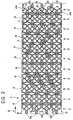
- each segment 2has a serpentine-like shape with a generally sinusoidal profile.
- the aforesaid serpentine-like shapeassumes a more complex shape which may be seen hypothetically as being derived from the shape shown in Figure 1 due to a "squeezing" of the apex part 2a of each of the half-waves of the sinusoidal path illustrated in Figure 1 until it achieves an almost lobe-like shape.
- the segments 2have a serpentine-like shape with successive loop parts having a generally opposite concavity.
- each segment 2the aforesaid loop parts open alternately towards the left and right (with reference to the plane of the drawing in Figures 1 and 2) in an arrangement in which the shapes of adjacent segments 2 may be seen, as it were, as opposite in phase (that is, offset by 180°), so that the concavity of each loop faces the concavity of an adjacent segment 2, and the respective convexity faces the convexity of the adjacent segment 2 on the opposite side.
- the aforesaid connector parts 4correspond in practice to the crossings of the zero points of the theoretical sinusoidal path of the segments 2 and extend - when the stent is in the radially-contracted position - substantially in the longitudinal direction of the stent 1 itself, that is, along the z-axis.
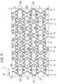
- the aforesaid connector parts 4are also generally straight and extend to connect the loop parts that are crushed or squeezed (as defined above in relation to the stent 1 in the radially-contracted condition, that is, as shown in Figure 2) in a generally oblique direction, and practically at approximately 45° with respect to the longitudinal axis z of the stent, maintaining this orientation substantially unchanged even during the radial expansion of the stent 1 so that, when the stent is expanded (Figure 3), the connector parts 4 constitute the central portions of the sides of the triangular wave profile assumed by each segment 2.
- the connector parts 4form, with respect to the aforesaid longitudinal axis z, alternate positive and negative angles (that is, approximately +45°, -45°, +45°, -45° etc ... the sign of the aforesaid angle being in itself irrelevant, in that what counts is the inversion of the sign itself in the sequence of connector parts 4).
- bridges 3connect to the segments 2 not only at the loops thereof, but also at the connector parts 4 and, in particular, at a median position thereof.
- the bridges 3attach to the segments 2 approximately in correspondence with the zero points of the respective sinusoidal paths.
- the bridges 3have generally curved and extended end parts 3a at the end connected to the connector parts 4 in a theoretical transverse plane with respect to the stent 1 (that is, in a generally orthogonal plane with respect to the longitudinal axis z).
- the bridges 3preferably have a curved profile which, in the embodiments illustrated, corresponds substantially to a V-shape.
- the two branches of the Vpreferably have distal connector parts at the end regions 3a which extend in an approximately longitudinal direction (z axis) with respect to the stent 1.
- V-shape(but a different shape of equivalent concave-convex type can equally well be used within the ambit of the present invention) enables the formation of a very strong connection between adjacent segments of the stent 1.
- a bridge 3can be present for connection to the adjacent segment 2 "to the left", and another bridge 3 for connecting to the adjacent segment 2 "to the right".
- the aboveapplies to the single adjacent segment 2.
- the rigid parts (that is, in the example illustrated, the V-shape parts) of the bridges 3are all orientated with their convexity (or concavity) facing in the same direction, so as to enable the possible co-penetration of the extensions of adjacent bridges 3 (that is, with the convex part of one of the bridges 3 penetrating the concave part of the adjacent bridge 3, and thus going beyond the condition of overall tangency adopted in the embodiment shown by way of example in Figure 1).
- FIG. 2 and 3actually adopts a bridge structure 3 having a general V-shape, single step alternating sequence, with the concavity/convexity of adjacent bridges 3 alternating in the sense of a theoretical path along the periphery of the stent 1.
- the bridges 3 of the embodiment of Figures 2 and 3also have their respective end parts 3a orientated, for example, at an angle of approximately 45°, with respect to the longitudinal axis z of the stent.
- the bridges 3connect the same connector parts 4 of a given segment 2 to the immediately adjacent segments which extend between them in a substantially co-linear position.
- the wall of the stentpasses from the "clover-leaf" configuration theoretically recognisable in Figure 2 to the reticular structure shown in Figure 3 in which the stent wall may theoretically be seen as constituted by a succession of approximately quadrangular closed loops (although with a mixtilinear outline), each having a greater dimension, with each loop joining peripherally with four adjacent loops having their greater dimensions orientated at right angles.
- the connection between adjacent loopsoccurs at portions of the wall orientated generally at an angle (that is, substantially 45°) to the direction of the longitudinal axis z of the stent.
Landscapes
- Health & Medical Sciences (AREA)
- Engineering & Computer Science (AREA)
- Biomedical Technology (AREA)
- Heart & Thoracic Surgery (AREA)
- Life Sciences & Earth Sciences (AREA)
- Cardiology (AREA)
- Oral & Maxillofacial Surgery (AREA)
- Transplantation (AREA)
- Physics & Mathematics (AREA)
- Vascular Medicine (AREA)
- Optics & Photonics (AREA)
- Animal Behavior & Ethology (AREA)
- General Health & Medical Sciences (AREA)
- Public Health (AREA)
- Veterinary Medicine (AREA)
- Prostheses (AREA)
- Media Introduction/Drainage Providing Device (AREA)
- Crystals, And After-Treatments Of Crystals (AREA)
- Materials For Medical Uses (AREA)
Abstract
Description
- ensuring that, while moving towards the treatmentsite, the stent is capable of adapting with sufficientmalleability to the path taken, even as regards less curvedsections such as those which may exist, for example, in someperipheral vessels; all of this without detrimentallyaffecting the ability of the stent to provide an effectivesupport action once positioned and deployed;
- avoiding, or at least limiting, the longitudinalshortening effect which occurs in many stents on deployment,
- achieving the maximum homogeneity and uniformity inthe expansion movement, avoiding (when this is not a requiredeffect) a situation in which this movement manifests itself toan extent and at times which vary in different areas orsections of the stent;
- providing the wall of the lumen which is beingsupported with a support surface that is as extensive aspossible;
- avoiding the origination of complex shapes and/orpossible stagnation sites susceptible, especially in bloodvessels, of giving rise to negative phenomena such ascoagulation, thrombosis, etc; and
- reconciling the requirements described above with themodality and criteria of simple production, reliability andthe introduction of currently available technology.
- Figure 1 illustrates, in a theoretical plane, thegeometrical characteristics of the wall of a stent forangioplasty manufactured according to the invention,illustrated in the radially-contracted position;
- Figure 2 illustrates, in conditions substantiallysimilar to those of Figure 1, that is, in the radially-contractedcondition, another possible embodiment of theinvention; and
- Figure 3 illustrates, also in a theoretical plane, thegeometrical characteristics of the wall of the stent accordingto Figure 2 seen in the radially-expanded condition.
- forming the stent from a continuous tubular blankintended to be segmented into individual stents, with theapertured parts being formed using techniques such as laserincision, photo-incision, electroerosion, etc;
- forming the stent from a strip-like body in which theapertured zones are formed, for example, using the techniqueslisted above, with the subsequent closure of the strip-likeelement into a tube; and
- forming the stent from metal wire shaped by thesubsequent attachment of wire loops, for example, usingoperations of micro welding, brazing, gluing, crimping etc ...
Claims (11)
- A stent for angioplasty including a body (1) in the formof a generally tubular envelope capable of being dilated froma radially-contracted position to a radially-expandedposition, characterised in that:the said body includes a plurality of successivesegments (2) having a serpentine-like shape with opposite loopparts in sequence; the said loop parts being connected byconnector parts (4); andthe said successive segments (2) are connected to eachother by bridge elements (3) joined to the aforesaid connectorparts (4).
- A stent according to Claim 1, characterised in that thesaid loop parts are opposite each other in the sequence of thesaid successive segments (2).
- A stent according to Claim 1 or Claim 2, characterisedin that the said bridge elements (3) have an inflexible medianportion.
- A stent according to Claim 3, characterised in that thesaid bridge elements (3) have a general V-shape.
- A stent according to Claim 3 or Claim 4, characterisedin that the said bridge elements (3) are convex along theperiphery of the stent.
- A stent according to Claim 3 or Claim 4, characterisedin that the said bridge elements (3) have opposite, sequentialconvexity along the periphery of the stent.
- A stent according to any preceding claim characterisedin that:when the stent (1) is in the radially-contractedposition, the said connector parts (4) extend in a generallylongitudinal direction (z) with respect to the stent (1); andthe said bridge elements (3) have end parts (3a)which, when the stent (1) is in the radially-contractedposition, extend in a transverse direction with respect to thestent (1) itself.
- A stent according to any of the preceding Claims 1 to 6,characterised in that the said connector parts (4) extend ina generally oblique direction with respect to the longitudinalaxis of the stent (1) and are substantially unchangedfollowing the dilatation of the stent (1) from the saidradially-contracted position to the said radially-expandedposition.
- A stent according to Claim 8, characterised in that thesaid bridge elements (3) have end parts (3a) joined to thesaid connector parts (4) in a generally oblique direction withrespect to the longitudinal axis of the stent (1), these alsobeing substantially unchanged following the dilatation of thestent (1) from the said radially-contracted position to thesaid radially-expanded position.
- A stent according to any of Claims 1, 8 or 9,characterised in that to at least some of the said connectorparts (4) are joined associated pairs of bridge elements (3)connecting successive segments (2) in the said plurality in ageneral cross-shape.
- A stent according to any preceding claim, characterisedin that, in the said radially-contracted position, the saidloop parts have apex parts (2a) which extend along anapproximately lobe-shape path.
Priority Applications (2)
| Application Number | Priority Date | Filing Date | Title |
|---|---|---|---|
| EP01130177AEP1197188B1 (en) | 1997-04-29 | 1998-04-23 | A stent for angioplasty |
| DK01130177TDK1197188T3 (en) | 1997-04-29 | 1998-04-23 | Vascular stent |
Applications Claiming Priority (2)
| Application Number | Priority Date | Filing Date | Title |
|---|---|---|---|
| ITTO970369 | 1997-04-29 | ||
| IT97TO000369AIT1292295B1 (en) | 1997-04-29 | 1997-04-29 | ANGIOPLASTIC STENT |
Related Child Applications (1)
| Application Number | Title | Priority Date | Filing Date |
|---|---|---|---|
| EP01130177ADivisionEP1197188B1 (en) | 1997-04-29 | 1998-04-23 | A stent for angioplasty |
Publications (2)
| Publication Number | Publication Date |
|---|---|
| EP0875215A1true EP0875215A1 (en) | 1998-11-04 |
| EP0875215B1 EP0875215B1 (en) | 2002-11-06 |
Family
ID=11415681
Family Applications (2)
| Application Number | Title | Priority Date | Filing Date |
|---|---|---|---|
| EP98107382AExpired - LifetimeEP0875215B1 (en) | 1997-04-29 | 1998-04-23 | "A stent for angioplasty" |
| EP01130177AExpired - LifetimeEP1197188B1 (en) | 1997-04-29 | 1998-04-23 | A stent for angioplasty |
Family Applications After (1)
| Application Number | Title | Priority Date | Filing Date |
|---|---|---|---|
| EP01130177AExpired - LifetimeEP1197188B1 (en) | 1997-04-29 | 1998-04-23 | A stent for angioplasty |
Country Status (7)
| Country | Link |
|---|---|
| US (3) | US6325821B1 (en) |
| EP (2) | EP0875215B1 (en) |
| AT (2) | ATE297170T1 (en) |
| DE (2) | DE69809114T2 (en) |
| DK (2) | DK0875215T3 (en) |
| ES (2) | ES2184164T3 (en) |
| IT (1) | IT1292295B1 (en) |
Cited By (28)
| Publication number | Priority date | Publication date | Assignee | Title |
|---|---|---|---|---|
| WO1999044543A1 (en)* | 1998-03-04 | 1999-09-10 | Scimed Life Systems, Inc. | Improved stent cell configurations |
| WO2000002502A1 (en)* | 1998-07-08 | 2000-01-20 | Scimed Life Systems, Inc. | An improved stent |
| EP0962194A3 (en)* | 1998-06-02 | 2000-04-19 | Bard Connaught | Expandable stent having articulated connecting rods |
| EP1080738A1 (en) | 1999-08-05 | 2001-03-07 | SORIN BIOMEDICA CARDIO S.p.A. | Angioplasty stent |
| EP1088528A1 (en)* | 1999-10-01 | 2001-04-04 | SORIN BIOMEDICA CARDIO S.p.A. | Stents for angioplasty |
| EP1103234A1 (en) | 1999-11-23 | 2001-05-30 | SORIN BIOMEDICA CARDIO S.p.A. | A device for conveying radioactive agents on angioplasty stents, respective method and kit |
| DE19957063A1 (en)* | 1999-11-26 | 2001-08-02 | Franz Herbst | Stent and method for its manufacture |
| EP1212986A1 (en) | 2000-12-08 | 2002-06-12 | SORIN BIOMEDICA CARDIO S.p.A. | An angioplasty stent and manufacturing method thereof |
| EP1260197A1 (en)* | 2001-03-02 | 2002-11-27 | Cordis Corporation | Flexible stent |
| EP1277449A1 (en) | 2001-07-20 | 2003-01-22 | SORIN BIOMEDICA CARDIO S.p.A. | Stent |
| WO2002026163A3 (en)* | 2000-09-25 | 2003-03-06 | G David Jang | Intravascular stent apparatus |
| EP1310242A1 (en) | 2001-11-13 | 2003-05-14 | SORIN BIOMEDICA CARDIO S.p.A. | Carrier and kit for endoluminal delivery of active principles |
| US6565602B2 (en) | 1997-11-04 | 2003-05-20 | Sorin Biomedica Cardio S.P.A. | Angioplasty stents |
| EP1561436A1 (en) | 2004-02-05 | 2005-08-10 | SORIN BIOMEDICA CARDIO S.r.l. | A stent for endoluminal delivery of active principles or agents |
| US6955686B2 (en) | 2001-03-01 | 2005-10-18 | Cordis Corporation | Flexible stent |
| US6998060B2 (en) | 2001-03-01 | 2006-02-14 | Cordis Corporation | Flexible stent and method of manufacture |
| US7081130B2 (en) | 1996-04-26 | 2006-07-25 | Boston Scientific Scimed, Inc. | Intravascular Stent |
| EP1277489A4 (en)* | 2000-04-20 | 2007-03-14 | Kawasumi Lab Inc | VASCULAR ENDOPROTHESIS |
| EP1844741A3 (en)* | 1997-10-09 | 2007-10-24 | Boston Scientific Limited | Improved stent configurations |
| US7326241B2 (en) | 1996-04-26 | 2008-02-05 | Boston Scientific Scimed, Inc. | Intravascular stent |
| US7431732B2 (en) | 2001-01-15 | 2008-10-07 | Terumo Kabushiki Kaisha | Stent with waved connecting members |
| US7607208B2 (en) | 1996-12-30 | 2009-10-27 | Sorin Biomedica Cardio S.R.L. | Method of making a medicated stent |
| US7766956B2 (en) | 2000-09-22 | 2010-08-03 | Boston Scientific Scimed, Inc. | Intravascular stent and assembly |
| EP2253339A1 (en) | 2003-02-21 | 2010-11-24 | Sorin Biomedica Cardio S.r.l. | A process for producing stents and corresponding stent |
| US8562665B2 (en) | 1998-02-02 | 2013-10-22 | Boston Scientific Scimed, Inc. | Tubular stent consists of chevron-shape expansion struts and contralaterally attached diagonal-connectors |
| US9445926B2 (en) | 1996-04-26 | 2016-09-20 | Boston Scientific Scimed, Inc. | Intravascular stent |
| US9968471B1 (en) | 2000-03-01 | 2018-05-15 | Medinol Ltd. | Longitudinally flexible stent |
| IT201900003579A1 (en) | 2019-03-12 | 2020-09-12 | Alvimedica Tibbi Ueruenler Sanayi Ve Dis Ticaret A S | STENT FOR CORONARY OSTIUM |
Families Citing this family (137)
| Publication number | Priority date | Publication date | Assignee | Title |
|---|---|---|---|---|
| US7220275B2 (en) | 1996-11-04 | 2007-05-22 | Advanced Stent Technologies, Inc. | Stent with protruding branch portion for bifurcated vessels |
| US7341598B2 (en) | 1999-01-13 | 2008-03-11 | Boston Scientific Scimed, Inc. | Stent with protruding branch portion for bifurcated vessels |
| US6325826B1 (en) | 1998-01-14 | 2001-12-04 | Advanced Stent Technologies, Inc. | Extendible stent apparatus |
| US6599316B2 (en) | 1996-11-04 | 2003-07-29 | Advanced Stent Technologies, Inc. | Extendible stent apparatus |
| EP1723931B1 (en) | 1996-11-04 | 2012-01-04 | Advanced Stent Technologies, Inc. | Extendible stent apparatus and method for deploying the same |
| US6692483B2 (en) | 1996-11-04 | 2004-02-17 | Advanced Stent Technologies, Inc. | Catheter with attached flexible side sheath |
| US6835203B1 (en) | 1996-11-04 | 2004-12-28 | Advanced Stent Technologies, Inc. | Extendible stent apparatus |
| US8211167B2 (en) | 1999-12-06 | 2012-07-03 | Boston Scientific Scimed, Inc. | Method of using a catheter with attached flexible side sheath |
| US7591846B2 (en) | 1996-11-04 | 2009-09-22 | Boston Scientific Scimed, Inc. | Methods for deploying stents in bifurcations |
| IT1292295B1 (en)* | 1997-04-29 | 1999-01-29 | Sorin Biomedica Cardio Spa | ANGIOPLASTIC STENT |
| DK174814B1 (en)* | 1998-02-25 | 2003-12-01 | Cook William Europ | stent device |
| US7713297B2 (en) | 1998-04-11 | 2010-05-11 | Boston Scientific Scimed, Inc. | Drug-releasing stent with ceramic-containing layer |
| US7655030B2 (en) | 2003-07-18 | 2010-02-02 | Boston Scientific Scimed, Inc. | Catheter balloon systems and methods |
| US6884258B2 (en) | 1999-06-04 | 2005-04-26 | Advanced Stent Technologies, Inc. | Bifurcation lesion stent delivery using multiple guidewires |
| US6689156B1 (en) | 1999-09-23 | 2004-02-10 | Advanced Stent Technologies, Inc. | Stent range transducers and methods of use |
| US8496699B2 (en) | 2000-03-01 | 2013-07-30 | Medinol Ltd. | Longitudinally flexible stent |
| US8202312B2 (en) | 2000-03-01 | 2012-06-19 | Medinol Ltd. | Longitudinally flexible stent |
| US7141062B1 (en) | 2000-03-01 | 2006-11-28 | Medinol, Ltd. | Longitudinally flexible stent |
| EP1132058A1 (en) | 2000-03-06 | 2001-09-12 | Advanced Laser Applications Holding S.A. | Intravascular prothesis |
| US7070614B1 (en)* | 2000-05-22 | 2006-07-04 | Malte Neuss | Radially expandable vessel support |
| US8034097B2 (en)* | 2000-05-22 | 2011-10-11 | Malte Neuss | Radially expandable vessel support |
| US6929660B1 (en)* | 2000-12-22 | 2005-08-16 | Advanced Cardiovascular Systems, Inc. | Intravascular stent |
| CA2436642A1 (en)* | 2001-02-01 | 2002-08-08 | Kaneka Corporation | Stent |
| US6790227B2 (en) | 2001-03-01 | 2004-09-14 | Cordis Corporation | Flexible stent |
| US6679911B2 (en) | 2001-03-01 | 2004-01-20 | Cordis Corporation | Flexible stent |
| DE10118944B4 (en) | 2001-04-18 | 2013-01-31 | Merit Medical Systems, Inc. | Removable, essentially cylindrical implants |
| US8617231B2 (en) | 2001-05-18 | 2013-12-31 | Boston Scientific Scimed, Inc. | Dual guidewire exchange catheter system |
| US6939373B2 (en) | 2003-08-20 | 2005-09-06 | Advanced Cardiovascular Systems, Inc. | Intravascular stent |
| US6629994B2 (en) | 2001-06-11 | 2003-10-07 | Advanced Cardiovascular Systems, Inc. | Intravascular stent |
| WO2003002243A2 (en) | 2001-06-27 | 2003-01-09 | Remon Medical Technologies Ltd. | Method and device for electrochemical formation of therapeutic species in vivo |
| AU2002320456A1 (en) | 2001-07-26 | 2003-02-17 | Alveolus Inc. | Removable stent and method of using the same |
| US7842083B2 (en) | 2001-08-20 | 2010-11-30 | Innovational Holdings, Llc. | Expandable medical device with improved spatial distribution |
| US20030077310A1 (en) | 2001-10-22 | 2003-04-24 | Chandrashekhar Pathak | Stent coatings containing HMG-CoA reductase inhibitors |
| US6656220B1 (en) | 2002-06-17 | 2003-12-02 | Advanced Cardiovascular Systems, Inc. | Intravascular stent |
| US7875068B2 (en) | 2002-11-05 | 2011-01-25 | Merit Medical Systems, Inc. | Removable biliary stent |
| US7959671B2 (en) | 2002-11-05 | 2011-06-14 | Merit Medical Systems, Inc. | Differential covering and coating methods |
| US7527644B2 (en) | 2002-11-05 | 2009-05-05 | Alveolus Inc. | Stent with geometry determinated functionality and method of making the same |
| US7637942B2 (en) | 2002-11-05 | 2009-12-29 | Merit Medical Systems, Inc. | Coated stent with geometry determinated functionality and method of making the same |
| DE10261822A1 (en)* | 2002-12-20 | 2004-07-01 | Biotronik Meß- und Therapiegeräte GmbH & Co. Ingenieurbüro Berlin | Helix bridge connection |
| US20070239251A1 (en)* | 2002-12-31 | 2007-10-11 | Abbott Cardiovascular Systems Inc. | Flexible stent |
| CA2519226C (en)* | 2003-03-19 | 2013-01-15 | Advanced Bio Prosthetic Surfaces, Ltd. | Endoluminal stent having mid-strut interconnecting members |
| US6846323B2 (en) | 2003-05-15 | 2005-01-25 | Advanced Cardiovascular Systems, Inc. | Intravascular stent |
| JPWO2004108201A1 (en)* | 2003-06-02 | 2006-07-20 | ニプロ株式会社 | Flexible stent with good blood vessel tracking |
| US8298280B2 (en) | 2003-08-21 | 2012-10-30 | Boston Scientific Scimed, Inc. | Stent with protruding branch portion for bifurcated vessels |
| US7344557B2 (en) | 2003-11-12 | 2008-03-18 | Advanced Stent Technologies, Inc. | Catheter balloon systems and methods |
| US7479158B2 (en)* | 2004-02-20 | 2009-01-20 | Boston Scientific Scimed, Inc. | Stent with nested flexible connectors for flexibility and crimpability |
| US7887579B2 (en) | 2004-09-29 | 2011-02-15 | Merit Medical Systems, Inc. | Active stent |
| US7731654B2 (en) | 2005-05-13 | 2010-06-08 | Merit Medical Systems, Inc. | Delivery device with viewing window and associated method |
| US20090062909A1 (en) | 2005-07-15 | 2009-03-05 | Micell Technologies, Inc. | Stent with polymer coating containing amorphous rapamycin |
| WO2007011707A2 (en) | 2005-07-15 | 2007-01-25 | Micell Technologies, Inc. | Polymer coatings containing drug powder of controlled morphology |
| US8043366B2 (en) | 2005-09-08 | 2011-10-25 | Boston Scientific Scimed, Inc. | Overlapping stent |
| US8840660B2 (en) | 2006-01-05 | 2014-09-23 | Boston Scientific Scimed, Inc. | Bioerodible endoprostheses and methods of making the same |
| US8089029B2 (en) | 2006-02-01 | 2012-01-03 | Boston Scientific Scimed, Inc. | Bioabsorbable metal medical device and method of manufacture |
| US8821561B2 (en) | 2006-02-22 | 2014-09-02 | Boston Scientific Scimed, Inc. | Marker arrangement for bifurcation catheter |
| US20070224235A1 (en) | 2006-03-24 | 2007-09-27 | Barron Tenney | Medical devices having nanoporous coatings for controlled therapeutic agent delivery |
| US8187620B2 (en) | 2006-03-27 | 2012-05-29 | Boston Scientific Scimed, Inc. | Medical devices comprising a porous metal oxide or metal material and a polymer coating for delivering therapeutic agents |
| US8048150B2 (en) | 2006-04-12 | 2011-11-01 | Boston Scientific Scimed, Inc. | Endoprosthesis having a fiber meshwork disposed thereon |
| EP2944382A1 (en) | 2006-04-26 | 2015-11-18 | Micell Technologies, Inc. | Coatings containing multiple drugs |
| US8815275B2 (en) | 2006-06-28 | 2014-08-26 | Boston Scientific Scimed, Inc. | Coatings for medical devices comprising a therapeutic agent and a metallic material |
| WO2008002778A2 (en) | 2006-06-29 | 2008-01-03 | Boston Scientific Limited | Medical devices with selective coating |
| EP2054537A2 (en) | 2006-08-02 | 2009-05-06 | Boston Scientific Scimed, Inc. | Endoprosthesis with three-dimensional disintegration control |
| EP2068757B1 (en) | 2006-09-14 | 2011-05-11 | Boston Scientific Limited | Medical devices with drug-eluting coating |
| ES2357661T3 (en) | 2006-09-15 | 2011-04-28 | Boston Scientific Scimed, Inc. | BIOEROSIONABLE ENDOPROOTHESIS WITH BIOESTABLE INORGANIC LAYERS. |
| WO2008034066A1 (en) | 2006-09-15 | 2008-03-20 | Boston Scientific Limited | Bioerodible endoprostheses and methods of making the same |
| EP2959925B1 (en) | 2006-09-15 | 2018-08-29 | Boston Scientific Limited | Medical devices and methods of making the same |
| JP2010503489A (en) | 2006-09-15 | 2010-02-04 | ボストン サイエンティフィック リミテッド | Biodegradable endoprosthesis and method for producing the same |
| WO2008036548A2 (en) | 2006-09-18 | 2008-03-27 | Boston Scientific Limited | Endoprostheses |
| US8778009B2 (en) | 2006-10-06 | 2014-07-15 | Abbott Cardiovascular Systems Inc. | Intravascular stent |
| US7981150B2 (en) | 2006-11-09 | 2011-07-19 | Boston Scientific Scimed, Inc. | Endoprosthesis with coatings |
| ES2506144T3 (en) | 2006-12-28 | 2014-10-13 | Boston Scientific Limited | Bioerodible endoprosthesis and their manufacturing procedure |
| EP2111184B1 (en) | 2007-01-08 | 2018-07-25 | Micell Technologies, Inc. | Stents having biodegradable layers |
| US11426494B2 (en) | 2007-01-08 | 2022-08-30 | MT Acquisition Holdings LLC | Stents having biodegradable layers |
| US8070797B2 (en) | 2007-03-01 | 2011-12-06 | Boston Scientific Scimed, Inc. | Medical device with a porous surface for delivery of a therapeutic agent |
| US8431149B2 (en) | 2007-03-01 | 2013-04-30 | Boston Scientific Scimed, Inc. | Coated medical devices for abluminal drug delivery |
| US8974514B2 (en)* | 2007-03-13 | 2015-03-10 | Abbott Cardiovascular Systems Inc. | Intravascular stent with integrated link and ring strut |
| US8067054B2 (en) | 2007-04-05 | 2011-11-29 | Boston Scientific Scimed, Inc. | Stents with ceramic drug reservoir layer and methods of making and using the same |
| US9433516B2 (en) | 2007-04-17 | 2016-09-06 | Micell Technologies, Inc. | Stents having controlled elution |
| US7976915B2 (en) | 2007-05-23 | 2011-07-12 | Boston Scientific Scimed, Inc. | Endoprosthesis with select ceramic morphology |
| US7867273B2 (en)* | 2007-06-27 | 2011-01-11 | Abbott Laboratories | Endoprostheses for peripheral arteries and other body vessels |
| US8002823B2 (en) | 2007-07-11 | 2011-08-23 | Boston Scientific Scimed, Inc. | Endoprosthesis coating |
| US7942926B2 (en) | 2007-07-11 | 2011-05-17 | Boston Scientific Scimed, Inc. | Endoprosthesis coating |
| US8205317B2 (en)* | 2007-07-16 | 2012-06-26 | Medtronic Vascular, Inc. | Method of manufacturing a controlled porosity stent |
| EP2187988B1 (en) | 2007-07-19 | 2013-08-21 | Boston Scientific Limited | Endoprosthesis having a non-fouling surface |
| US8815273B2 (en) | 2007-07-27 | 2014-08-26 | Boston Scientific Scimed, Inc. | Drug eluting medical devices having porous layers |
| US7931683B2 (en) | 2007-07-27 | 2011-04-26 | Boston Scientific Scimed, Inc. | Articles having ceramic coated surfaces |
| WO2009018340A2 (en) | 2007-07-31 | 2009-02-05 | Boston Scientific Scimed, Inc. | Medical device coating by laser cladding |
| US8486134B2 (en) | 2007-08-01 | 2013-07-16 | Boston Scientific Scimed, Inc. | Bifurcation treatment system and methods |
| JP2010535541A (en) | 2007-08-03 | 2010-11-25 | ボストン サイエンティフィック リミテッド | Coating for medical devices with large surface area |
| US8052745B2 (en) | 2007-09-13 | 2011-11-08 | Boston Scientific Scimed, Inc. | Endoprosthesis |
| US7938855B2 (en) | 2007-11-02 | 2011-05-10 | Boston Scientific Scimed, Inc. | Deformable underlayer for stent |
| US8216632B2 (en) | 2007-11-02 | 2012-07-10 | Boston Scientific Scimed, Inc. | Endoprosthesis coating |
| US8029554B2 (en) | 2007-11-02 | 2011-10-04 | Boston Scientific Scimed, Inc. | Stent with embedded material |
| US7972373B2 (en)* | 2007-12-19 | 2011-07-05 | Advanced Technologies And Regenerative Medicine, Llc | Balloon expandable bioabsorbable stent with a single stress concentration region interconnecting adjacent struts |
| US8747456B2 (en) | 2007-12-31 | 2014-06-10 | Boston Scientific Scimed, Inc. | Bifurcation stent delivery system and methods |
| MX350637B (en) | 2008-04-17 | 2017-09-11 | Micell Technologies Inc | Stents having bioabsorbable layers. |
| US8920491B2 (en) | 2008-04-22 | 2014-12-30 | Boston Scientific Scimed, Inc. | Medical devices having a coating of inorganic material |
| US8932346B2 (en) | 2008-04-24 | 2015-01-13 | Boston Scientific Scimed, Inc. | Medical devices having inorganic particle layers |
| US7998192B2 (en) | 2008-05-09 | 2011-08-16 | Boston Scientific Scimed, Inc. | Endoprostheses |
| US8377108B2 (en) | 2008-06-02 | 2013-02-19 | Boston Scientific Scimed, Inc. | Staggered two balloon bifurcation catheter assembly and methods |
| WO2009149405A1 (en) | 2008-06-05 | 2009-12-10 | Boston Scientific Scimed, Inc. | Balloon bifurcated lumen treatment |
| JP5662310B2 (en) | 2008-06-05 | 2015-01-28 | ボストン サイエンティフィック サイムド,インコーポレイテッドBoston Scientific Scimed,Inc. | Shrinkable branch device and method of manufacturing the same |
| US8236046B2 (en) | 2008-06-10 | 2012-08-07 | Boston Scientific Scimed, Inc. | Bioerodible endoprosthesis |
| EP2303350A2 (en) | 2008-06-18 | 2011-04-06 | Boston Scientific Scimed, Inc. | Endoprosthesis coating |
| JP2011528275A (en) | 2008-07-17 | 2011-11-17 | ミセル テクノロジーズ,インク. | Drug delivery medical device |
| US7985252B2 (en) | 2008-07-30 | 2011-07-26 | Boston Scientific Scimed, Inc. | Bioerodible endoprosthesis |
| US8382824B2 (en) | 2008-10-03 | 2013-02-26 | Boston Scientific Scimed, Inc. | Medical implant having NANO-crystal grains with barrier layers of metal nitrides or fluorides |
| US8231980B2 (en) | 2008-12-03 | 2012-07-31 | Boston Scientific Scimed, Inc. | Medical implants including iridium oxide |
| EP2403546A2 (en) | 2009-03-02 | 2012-01-11 | Boston Scientific Scimed, Inc. | Self-buffering medical implants |
| US8071156B2 (en) | 2009-03-04 | 2011-12-06 | Boston Scientific Scimed, Inc. | Endoprostheses |
| US9981072B2 (en) | 2009-04-01 | 2018-05-29 | Micell Technologies, Inc. | Coated stents |
| US8287937B2 (en) | 2009-04-24 | 2012-10-16 | Boston Scientific Scimed, Inc. | Endoprosthese |
| EP2453834A4 (en) | 2009-07-16 | 2014-04-16 | Micell Technologies Inc | Drug delivery medical device |
| KR101137896B1 (en)* | 2009-11-12 | 2012-05-02 | 연세대학교 산학협력단 | Branch Vessel Protection Stent on Branch Lesions |
| EP2531140B1 (en) | 2010-02-02 | 2017-11-01 | Micell Technologies, Inc. | Stent and stent delivery system with improved deliverability |
| US8668732B2 (en) | 2010-03-23 | 2014-03-11 | Boston Scientific Scimed, Inc. | Surface treated bioerodible metal endoprostheses |
| WO2011133655A1 (en) | 2010-04-22 | 2011-10-27 | Micell Technologies, Inc. | Stents and other devices having extracellular matrix coating |
| EP2593039B1 (en) | 2010-07-16 | 2022-11-30 | Micell Technologies, Inc. | Drug delivery medical device |
| US10117972B2 (en) | 2011-07-15 | 2018-11-06 | Micell Technologies, Inc. | Drug delivery medical device |
| US10188772B2 (en) | 2011-10-18 | 2019-01-29 | Micell Technologies, Inc. | Drug delivery medical device |
| JP6220386B2 (en) | 2012-05-14 | 2017-10-25 | シー・アール・バード・インコーポレーテッドC R Bard Incorporated | Uniformly expandable stent |
| JP6330024B2 (en) | 2013-03-12 | 2018-05-23 | マイセル・テクノロジーズ,インコーポレイテッド | Bioabsorbable biomedical implant |
| USD723165S1 (en) | 2013-03-12 | 2015-02-24 | C. R. Bard, Inc. | Stent |
| US10271975B2 (en) | 2013-03-15 | 2019-04-30 | Atrium Medical Corporation | Stent device having reduced foreshortening and recoil and method of making same |
| KR20180059584A (en) | 2013-05-15 | 2018-06-04 | 미셀 테크놀로지즈, 인코포레이티드 | Bioabsorbable biomedical implants |
| JP6081948B2 (en)* | 2014-03-25 | 2017-02-15 | 株式会社World Medish Technology | Flexible stent |
| US9381103B2 (en)* | 2014-10-06 | 2016-07-05 | Abbott Cardiovascular Systems Inc. | Stent with elongating struts |
| US10758381B2 (en) | 2016-03-31 | 2020-09-01 | Vesper Medical, Inc. | Intravascular implants |
| US10758384B2 (en)* | 2016-07-13 | 2020-09-01 | Cook Medical Technologies Llc | Stent having reduced foreshortening |
| US10238513B2 (en) | 2017-07-19 | 2019-03-26 | Abbott Cardiovascular Systems Inc. | Intravascular stent |
| US10849769B2 (en) | 2017-08-23 | 2020-12-01 | Vesper Medical, Inc. | Non-foreshortening stent |
| US11628076B2 (en) | 2017-09-08 | 2023-04-18 | Vesper Medical, Inc. | Hybrid stent |
| US10271977B2 (en) | 2017-09-08 | 2019-04-30 | Vesper Medical, Inc. | Hybrid stent |
| US11357650B2 (en) | 2019-02-28 | 2022-06-14 | Vesper Medical, Inc. | Hybrid stent |
| US10835398B2 (en) | 2017-11-03 | 2020-11-17 | Covidien Lp | Meshes and devices for treating vascular defects |
| US11364134B2 (en) | 2018-02-15 | 2022-06-21 | Vesper Medical, Inc. | Tapering stent |
| US10500078B2 (en) | 2018-03-09 | 2019-12-10 | Vesper Medical, Inc. | Implantable stent |
| US11517457B2 (en) | 2019-07-03 | 2022-12-06 | Abbott Cardiovascular Systems Inc. | Intravascular stent |
Citations (11)
| Publication number | Priority date | Publication date | Assignee | Title |
|---|---|---|---|---|
| US4503569A (en) | 1983-03-03 | 1985-03-12 | Dotter Charles T | Transluminally placed expandable graft prosthesis |
| US4768507A (en) | 1986-02-24 | 1988-09-06 | Medinnovations, Inc. | Intravascular stent and percutaneous insertion catheter system for the dilation of an arterial stenosis and the prevention of arterial restenosis |
| US4776337A (en) | 1985-11-07 | 1988-10-11 | Expandable Grafts Partnership | Expandable intraluminal graft, and method and apparatus for implanting an expandable intraluminal graft |
| US4800882A (en) | 1987-03-13 | 1989-01-31 | Cook Incorporated | Endovascular stent and delivery system |
| US4830003A (en) | 1988-06-17 | 1989-05-16 | Wolff Rodney G | Compressive stent and delivery system |
| US4856516A (en) | 1989-01-09 | 1989-08-15 | Cordis Corporation | Endovascular stent apparatus and method |
| US4886062A (en) | 1987-10-19 | 1989-12-12 | Medtronic, Inc. | Intravascular radially expandable stent and method of implant |
| US4907336A (en) | 1987-03-13 | 1990-03-13 | Cook Incorporated | Method of making an endovascular stent and delivery system |
| WO1996003092A1 (en)* | 1994-07-28 | 1996-02-08 | Brun, Heidi, M. | A flexible expandable stent |
| DE29701758U1 (en)* | 1997-02-01 | 1997-03-27 | Jomed Implantate GmbH, 72414 Rangendingen | Radially expandable stent for implantation in a body vessel, particularly in the area of a vascular branch |
| DE29702671U1 (en)* | 1997-02-17 | 1997-04-10 | Jomed Implantate GmbH, 72414 Rangendingen | Stent |
Family Cites Families (42)
| Publication number | Priority date | Publication date | Assignee | Title |
|---|---|---|---|---|
| SE450809B (en) | 1985-04-10 | 1987-08-03 | Medinvent Sa | PLANT TOPIC PROVIDED FOR MANUFACTURING A SPIRAL SPRING SUITABLE FOR TRANSLUMINAL IMPLANTATION AND MANUFACTURED SPIRAL SPRINGS |
| CA2079417C (en) | 1991-10-28 | 2003-01-07 | Lilip Lau | Expandable stents and method of making same |
| US5718813A (en)* | 1992-12-30 | 1998-02-17 | Advanced Energy Industries, Inc. | Enhanced reactive DC sputtering system |
| JP2703510B2 (en) | 1993-12-28 | 1998-01-26 | アドヴァンスド カーディオヴァスキュラー システムズ インコーポレーテッド | Expandable stent and method of manufacturing the same |
| US5449373A (en)* | 1994-03-17 | 1995-09-12 | Medinol Ltd. | Articulated stent |
| JP2825452B2 (en) | 1994-04-25 | 1998-11-18 | アドヴァンスド カーディオヴァスキュラー システムズ インコーポレーテッド | Radiopak stent marker |
| EP0790810B1 (en) | 1994-11-09 | 2004-04-28 | Endotex Interventional Systems, Inc. | Kit of delivery catheter and graft for aneurysm repair |
| CA2301351C (en) | 1994-11-28 | 2002-01-22 | Advanced Cardiovascular Systems, Inc. | Method and apparatus for direct laser cutting of metal stents |
| US5591197A (en) | 1995-03-14 | 1997-01-07 | Advanced Cardiovascular Systems, Inc. | Expandable stent forming projecting barbs and method for deploying |
| US5728131A (en) | 1995-06-12 | 1998-03-17 | Endotex Interventional Systems, Inc. | Coupling device and method of use |
| US5776161A (en)* | 1995-10-16 | 1998-07-07 | Instent, Inc. | Medical stents, apparatus and method for making same |
| US5938682A (en) | 1996-01-26 | 1999-08-17 | Cordis Corporation | Axially flexible stent |
| US5695516A (en) | 1996-02-21 | 1997-12-09 | Iso Stent, Inc. | Longitudinally elongating balloon expandable stent |
| EP1066804B1 (en) | 1996-03-05 | 2004-07-14 | Evysio Medical Devices Ulc | Expandable stent |
| US6334871B1 (en)* | 1996-03-13 | 2002-01-01 | Medtronic, Inc. | Radiopaque stent markers |
| NZ331269A (en)* | 1996-04-10 | 2000-01-28 | Advanced Cardiovascular System | Expandable stent, its structural strength varying along its length |
| UA58485C2 (en)* | 1996-05-03 | 2003-08-15 | Медінол Лтд. | Method for manufacture of bifurcated stent (variants) and bifurcated stent (variants) |
| US5697971A (en) | 1996-06-11 | 1997-12-16 | Fischell; Robert E. | Multi-cell stent with cells having differing characteristics |
| IT1284708B1 (en) | 1996-07-26 | 1998-05-21 | Sorin Biomedica Cardio Spa | ANGIOPLASTIC STENT |
| US5755781A (en)* | 1996-08-06 | 1998-05-26 | Iowa-India Investments Company Limited | Embodiments of multiple interconnected stents |
| US5776183A (en) | 1996-08-23 | 1998-07-07 | Kanesaka; Nozomu | Expandable stent |
| US5807404A (en)* | 1996-09-19 | 1998-09-15 | Medinol Ltd. | Stent with variable features to optimize support and method of making such stent |
| US5755776A (en) | 1996-10-04 | 1998-05-26 | Al-Saadon; Khalid | Permanent expandable intraluminal tubular stent |
| IT1289728B1 (en)* | 1996-12-10 | 1998-10-16 | Sorin Biomedica Cardio Spa | SYSTEM AND EQUIPMENT DEVICE THAT INCLUDES IT |
| FR2758253B1 (en) | 1997-01-10 | 1999-04-02 | Nycomed Lab Sa | IMPLANTABLE DEVICE FOR THE TREATMENT OF A BODY DUCT |
| US5733330A (en) | 1997-01-13 | 1998-03-31 | Advanced Cardiovascular Systems, Inc. | Balloon-expandable, crush-resistant locking stent |
| US5759174A (en) | 1997-01-29 | 1998-06-02 | Cathco, Inc. | Angioplasty balloon with an expandable external radiopaque marker band |
| US5827321A (en)* | 1997-02-07 | 1998-10-27 | Cornerstone Devices, Inc. | Non-Foreshortening intraluminal prosthesis |
| US5718713A (en) | 1997-04-10 | 1998-02-17 | Global Therapeutics, Inc. | Surgical stent having a streamlined contour |
| DE19717477C2 (en) | 1997-04-25 | 1999-12-09 | Heraeus Gmbh W C | Radially expandable support structure for keeping lumens open within a body |
| DE19717476C2 (en) | 1997-04-25 | 1999-06-17 | Heraeus Gmbh W C | Radially expandable support structure |
| US6033433A (en)* | 1997-04-25 | 2000-03-07 | Scimed Life Systems, Inc. | Stent configurations including spirals |
| IT1292295B1 (en)* | 1997-04-29 | 1999-01-29 | Sorin Biomedica Cardio Spa | ANGIOPLASTIC STENT |
| US6451049B2 (en)* | 1998-04-29 | 2002-09-17 | Sorin Biomedica Cardio, S.P.A. | Stents for angioplasty |
| US5741327A (en) | 1997-05-06 | 1998-04-21 | Global Therapeutics, Inc. | Surgical stent featuring radiopaque markers |
| US5913895A (en)* | 1997-06-02 | 1999-06-22 | Isostent, Inc. | Intravascular stent with enhanced rigidity strut members |
| IT1293973B1 (en)* | 1997-08-13 | 1999-03-15 | Sorin Biomedica Cardio Spa | ELEMENT FOR ANCHORING OF INSTALLATION DEVICES IN SITU. |
| JP4292710B2 (en) | 1997-09-24 | 2009-07-08 | エム イー ディ インスチィチュート インク | Radially expandable stent |
| US6309414B1 (en)* | 1997-11-04 | 2001-10-30 | Sorin Biomedica Cardio S.P.A. | Angioplasty stents |
| US5938697A (en)* | 1998-03-04 | 1999-08-17 | Scimed Life Systems, Inc. | Stent having variable properties |
| US6261319B1 (en) | 1998-07-08 | 2001-07-17 | Scimed Life Systems, Inc. | Stent |
| US6461380B1 (en) | 1998-07-28 | 2002-10-08 | Advanced Cardiovascular Systems, Inc. | Stent configuration |
- 1997
- 1997-04-29ITIT97TO000369Apatent/IT1292295B1/enactiveIP Right Grant
- 1998
- 1998-04-23EPEP98107382Apatent/EP0875215B1/ennot_activeExpired - Lifetime
- 1998-04-23DKDK98107382Tpatent/DK0875215T3/enactive
- 1998-04-23ATAT01130177Tpatent/ATE297170T1/ennot_activeIP Right Cessation
- 1998-04-23EPEP01130177Apatent/EP1197188B1/ennot_activeExpired - Lifetime
- 1998-04-23ESES98107382Tpatent/ES2184164T3/ennot_activeExpired - Lifetime
- 1998-04-23ATAT98107382Tpatent/ATE227110T1/ennot_activeIP Right Cessation
- 1998-04-23DEDE69809114Tpatent/DE69809114T2/ennot_activeExpired - Lifetime
- 1998-04-23ESES01130177Tpatent/ES2241739T3/ennot_activeExpired - Lifetime
- 1998-04-23DKDK01130177Tpatent/DK1197188T3/enactive
- 1998-04-23DEDE69830520Tpatent/DE69830520T2/ennot_activeExpired - Lifetime
- 1998-04-29USUS09/069,425patent/US6325821B1/ennot_activeExpired - Lifetime
- 2007
- 2007-09-25USUS11/860,805patent/US20080288048A1/ennot_activeAbandoned
- 2010
- 2010-06-03USUS12/793,341patent/US20100241216A1/ennot_activeAbandoned
Patent Citations (12)
| Publication number | Priority date | Publication date | Assignee | Title |
|---|---|---|---|---|
| US4503569A (en) | 1983-03-03 | 1985-03-12 | Dotter Charles T | Transluminally placed expandable graft prosthesis |
| US4776337A (en) | 1985-11-07 | 1988-10-11 | Expandable Grafts Partnership | Expandable intraluminal graft, and method and apparatus for implanting an expandable intraluminal graft |
| US4776337B1 (en) | 1985-11-07 | 2000-12-05 | Cordis Corp | Expandable intraluminal graft and method and apparatus for implanting an expandable intraluminal graft |
| US4768507A (en) | 1986-02-24 | 1988-09-06 | Medinnovations, Inc. | Intravascular stent and percutaneous insertion catheter system for the dilation of an arterial stenosis and the prevention of arterial restenosis |
| US4800882A (en) | 1987-03-13 | 1989-01-31 | Cook Incorporated | Endovascular stent and delivery system |
| US4907336A (en) | 1987-03-13 | 1990-03-13 | Cook Incorporated | Method of making an endovascular stent and delivery system |
| US4886062A (en) | 1987-10-19 | 1989-12-12 | Medtronic, Inc. | Intravascular radially expandable stent and method of implant |
| US4830003A (en) | 1988-06-17 | 1989-05-16 | Wolff Rodney G | Compressive stent and delivery system |
| US4856516A (en) | 1989-01-09 | 1989-08-15 | Cordis Corporation | Endovascular stent apparatus and method |
| WO1996003092A1 (en)* | 1994-07-28 | 1996-02-08 | Brun, Heidi, M. | A flexible expandable stent |
| DE29701758U1 (en)* | 1997-02-01 | 1997-03-27 | Jomed Implantate GmbH, 72414 Rangendingen | Radially expandable stent for implantation in a body vessel, particularly in the area of a vascular branch |
| DE29702671U1 (en)* | 1997-02-17 | 1997-04-10 | Jomed Implantate GmbH, 72414 Rangendingen | Stent |
Cited By (60)
| Publication number | Priority date | Publication date | Assignee | Title |
|---|---|---|---|---|
| US7326241B2 (en) | 1996-04-26 | 2008-02-05 | Boston Scientific Scimed, Inc. | Intravascular stent |
| US9445926B2 (en) | 1996-04-26 | 2016-09-20 | Boston Scientific Scimed, Inc. | Intravascular stent |
| US9078778B2 (en) | 1996-04-26 | 2015-07-14 | Boston Scientific Scimed, Inc. | Intravascular stent |
| US8021414B2 (en) | 1996-04-26 | 2011-09-20 | Boston Scientific Scimed, Inc. | Intravascular stent |
| US7081130B2 (en) | 1996-04-26 | 2006-07-25 | Boston Scientific Scimed, Inc. | Intravascular Stent |
| US7607208B2 (en) | 1996-12-30 | 2009-10-27 | Sorin Biomedica Cardio S.R.L. | Method of making a medicated stent |
| US7946019B2 (en) | 1996-12-30 | 2011-05-24 | Sorin Biomedica Cardio S.R.L. | Process for producing a stent for angioplasty |
| US7273494B2 (en) | 1997-04-29 | 2007-09-25 | Sorin Biomedica Cardio S.R.L. | Stents for angioplasty |
| EP1844741A3 (en)* | 1997-10-09 | 2007-10-24 | Boston Scientific Limited | Improved stent configurations |
| US7267684B2 (en) | 1997-11-04 | 2007-09-11 | Sorin Biomedica Cardio S.R.L. | Angioplasty stents |
| US6896698B2 (en) | 1997-11-04 | 2005-05-24 | Sorin Biomedica Cardio S.P.A. | Angioplasty stents |
| US8439965B2 (en) | 1997-11-04 | 2013-05-14 | Cid S.P.A. | Angioplasty stents |
| US6616690B2 (en) | 1997-11-04 | 2003-09-09 | Sorin Biomedica Cardio S.P.A. | Angioplasty stents |
| US6565602B2 (en) | 1997-11-04 | 2003-05-20 | Sorin Biomedica Cardio S.P.A. | Angioplasty stents |
| US8562665B2 (en) | 1998-02-02 | 2013-10-22 | Boston Scientific Scimed, Inc. | Tubular stent consists of chevron-shape expansion struts and contralaterally attached diagonal-connectors |
| US6231599B1 (en) | 1998-03-04 | 2001-05-15 | Scimed Life Systems, Inc. | Stent cell configurations |
| WO1999044543A1 (en)* | 1998-03-04 | 1999-09-10 | Scimed Life Systems, Inc. | Improved stent cell configurations |
| US6395020B1 (en) | 1998-03-04 | 2002-05-28 | Scimed Life Systems, Inc. | Stent cell configurations |
| US7655032B2 (en) | 1998-03-04 | 2010-02-02 | Boston Scientific Scimed, Inc. | Stent cell configurations |
| EP1656907A1 (en)* | 1998-03-04 | 2006-05-17 | Boston Scientific Limited | Improved stent cell configurations |
| US6451049B2 (en) | 1998-04-29 | 2002-09-17 | Sorin Biomedica Cardio, S.P.A. | Stents for angioplasty |
| EP0962194A3 (en)* | 1998-06-02 | 2000-04-19 | Bard Connaught | Expandable stent having articulated connecting rods |
| US8668731B2 (en) | 1998-07-08 | 2014-03-11 | Boston Scientific Scimed, Inc. | Stent |
| US7326243B2 (en) | 1998-07-08 | 2008-02-05 | Boston Scientific Scimed, Inc. | Stent |
| EP1477135A3 (en)* | 1998-07-08 | 2004-12-22 | Boston Scientific Limited | An improved stent |
| US7731746B2 (en) | 1998-07-08 | 2010-06-08 | Boston Scientific Scimed, Inc. | Stent |
| US6478816B2 (en) | 1998-07-08 | 2002-11-12 | Scimed Life Systems, Inc. | Stent |
| US6945993B2 (en) | 1998-07-08 | 2005-09-20 | Boston Scientific Scimed, Inc. | Stent |
| US8206432B2 (en) | 1998-07-08 | 2012-06-26 | Boston Scientific Scimed, Inc. | Stent |
| US6261319B1 (en) | 1998-07-08 | 2001-07-17 | Scimed Life Systems, Inc. | Stent |
| US8986367B2 (en) | 1998-07-08 | 2015-03-24 | Boston Scientific Scimed, Inc. | Stent |
| WO2000002502A1 (en)* | 1998-07-08 | 2000-01-20 | Scimed Life Systems, Inc. | An improved stent |
| US6491720B1 (en) | 1999-08-05 | 2002-12-10 | Sorin Biomedica S.P.A. | Angioplasty stent adapted to counter restenosis respective kit and components |
| EP1080738A1 (en) | 1999-08-05 | 2001-03-07 | SORIN BIOMEDICA CARDIO S.p.A. | Angioplasty stent |
| EP1088528A1 (en)* | 1999-10-01 | 2001-04-04 | SORIN BIOMEDICA CARDIO S.p.A. | Stents for angioplasty |
| US6585632B2 (en) | 1999-11-23 | 2003-07-01 | Sorin Biomedica Cardio S.P.A. | Device for conveying radioactive agents on angioplasty stents, respective method and kit |
| EP1103234A1 (en) | 1999-11-23 | 2001-05-30 | SORIN BIOMEDICA CARDIO S.p.A. | A device for conveying radioactive agents on angioplasty stents, respective method and kit |
| US6447439B1 (en) | 1999-11-23 | 2002-09-10 | Sorin Biomedica Cardio S.P.A. | Device for conveying radioactive agents on angioplasty stents, respective method and kit |
| DE19957063A1 (en)* | 1999-11-26 | 2001-08-02 | Franz Herbst | Stent and method for its manufacture |
| WO2001037761A3 (en)* | 1999-11-26 | 2001-11-01 | Franz Herbst | Stent and method for the production thereof |
| US9968471B1 (en) | 2000-03-01 | 2018-05-15 | Medinol Ltd. | Longitudinally flexible stent |
| EP1277489A4 (en)* | 2000-04-20 | 2007-03-14 | Kawasumi Lab Inc | VASCULAR ENDOPROTHESIS |
| US7766956B2 (en) | 2000-09-22 | 2010-08-03 | Boston Scientific Scimed, Inc. | Intravascular stent and assembly |
| WO2002026163A3 (en)* | 2000-09-25 | 2003-03-06 | G David Jang | Intravascular stent apparatus |
| EP1752114A1 (en)* | 2000-09-25 | 2007-02-14 | Boston Scientific Scimed, Inc. | Intravascular stent apparatus |
| EP1212986A1 (en) | 2000-12-08 | 2002-06-12 | SORIN BIOMEDICA CARDIO S.p.A. | An angioplasty stent and manufacturing method thereof |
| US7431732B2 (en) | 2001-01-15 | 2008-10-07 | Terumo Kabushiki Kaisha | Stent with waved connecting members |
| US6955686B2 (en) | 2001-03-01 | 2005-10-18 | Cordis Corporation | Flexible stent |
| US7594927B2 (en) | 2001-03-01 | 2009-09-29 | Cordis Corporation | Flexible stent |
| US6998060B2 (en) | 2001-03-01 | 2006-02-14 | Cordis Corporation | Flexible stent and method of manufacture |
| EP1260197A1 (en)* | 2001-03-02 | 2002-11-27 | Cordis Corporation | Flexible stent |
| AU784552B2 (en)* | 2001-03-02 | 2006-05-04 | Cardinal Health 529, Llc | Flexible stent |
| EP1277449A1 (en) | 2001-07-20 | 2003-01-22 | SORIN BIOMEDICA CARDIO S.p.A. | Stent |
| US7344563B2 (en) | 2001-07-20 | 2008-03-18 | Sorin Biomedica Cardio S.R.L. | Angioplasty stents |
| US6699281B2 (en) | 2001-07-20 | 2004-03-02 | Sorin Biomedica Cardio S.P.A. | Angioplasty stents |
| EP1310242A1 (en) | 2001-11-13 | 2003-05-14 | SORIN BIOMEDICA CARDIO S.p.A. | Carrier and kit for endoluminal delivery of active principles |
| US8084076B2 (en) | 2003-02-21 | 2011-12-27 | Sorin Biomedica Cardio S.R.L. | Process for producing stents and corresponding stents |
| EP2253339A1 (en) | 2003-02-21 | 2010-11-24 | Sorin Biomedica Cardio S.r.l. | A process for producing stents and corresponding stent |
| EP1561436A1 (en) | 2004-02-05 | 2005-08-10 | SORIN BIOMEDICA CARDIO S.r.l. | A stent for endoluminal delivery of active principles or agents |
| IT201900003579A1 (en) | 2019-03-12 | 2020-09-12 | Alvimedica Tibbi Ueruenler Sanayi Ve Dis Ticaret A S | STENT FOR CORONARY OSTIUM |
Also Published As
| Publication number | Publication date |
|---|---|
| EP0875215B1 (en) | 2002-11-06 |
| IT1292295B1 (en) | 1999-01-29 |
| US20100241216A1 (en) | 2010-09-23 |
| ATE297170T1 (en) | 2005-06-15 |
| ATE227110T1 (en) | 2002-11-15 |
| DE69809114D1 (en) | 2002-12-12 |
| ITTO970369A1 (en) | 1998-10-29 |
| ITTO970369A0 (en) | 1997-04-29 |
| ES2184164T3 (en) | 2003-04-01 |
| DE69830520T2 (en) | 2006-03-16 |
| ES2241739T3 (en) | 2005-11-01 |
| US20080288048A1 (en) | 2008-11-20 |
| DK0875215T3 (en) | 2003-03-10 |
| DK1197188T3 (en) | 2005-10-03 |
| US6325821B1 (en) | 2001-12-04 |
| DE69809114T2 (en) | 2003-10-02 |
| EP1197188A2 (en) | 2002-04-17 |
| DE69830520D1 (en) | 2005-07-14 |
| EP1197188A3 (en) | 2004-01-14 |
| EP1197188B1 (en) | 2005-06-08 |
Similar Documents
| Publication | Publication Date | Title |
|---|---|---|
| EP1197188B1 (en) | A stent for angioplasty | |
| US7273494B2 (en) | Stents for angioplasty | |
| EP1477136B1 (en) | Longitudinally flexible expandable stent | |
| US6997944B2 (en) | Apparatus and method for decreasing stent gap size | |
| JP4097402B2 (en) | Expandable unit cell and intraluminal stent | |
| US8114146B2 (en) | Longitudinally flexible expandable stent | |
| WO2001087401A1 (en) | Medical tube-like stent |
Legal Events
| Date | Code | Title | Description |
|---|---|---|---|
| PUAI | Public reference made under article 153(3) epc to a published international application that has entered the european phase | Free format text:ORIGINAL CODE: 0009012 | |
| AK | Designated contracting states | Kind code of ref document:A1 Designated state(s):AT BE CH CY DE DK ES FI FR GB GR IE IT LI LU MC NL | |
| AX | Request for extension of the european patent | Free format text:AL;LT;LV;MK;RO;SI | |
| 17P | Request for examination filed | Effective date:19990429 | |
| AKX | Designation fees paid | Free format text:AT BE CH CY DE DK ES FI FR GB GR IE IT LI LU MC NL | |
| RBV | Designated contracting states (corrected) | Designated state(s):AT BE CH DE DK ES FI FR GB GR IE IT LI LU NL PT SE | |
| GRAG | Despatch of communication of intention to grant | Free format text:ORIGINAL CODE: EPIDOS AGRA | |
| 17Q | First examination report despatched | Effective date:20010801 | |
| GRAG | Despatch of communication of intention to grant | Free format text:ORIGINAL CODE: EPIDOS AGRA | |
| GRAG | Despatch of communication of intention to grant | Free format text:ORIGINAL CODE: EPIDOS AGRA | |
| GRAH | Despatch of communication of intention to grant a patent | Free format text:ORIGINAL CODE: EPIDOS IGRA | |
| GRAH | Despatch of communication of intention to grant a patent | Free format text:ORIGINAL CODE: EPIDOS IGRA | |
| GRAA | (expected) grant | Free format text:ORIGINAL CODE: 0009210 | |
| AK | Designated contracting states | Kind code of ref document:B1 Designated state(s):AT BE CH DE DK ES FI FR GB GR IE IT LI LU NL PT SE | |
| PG25 | Lapsed in a contracting state [announced via postgrant information from national office to epo] | Ref country code:GR Free format text:LAPSE BECAUSE OF FAILURE TO SUBMIT A TRANSLATION OF THE DESCRIPTION OR TO PAY THE FEE WITHIN THE PRESCRIBED TIME-LIMIT Effective date:20021106 Ref country code:FI Free format text:LAPSE BECAUSE OF FAILURE TO SUBMIT A TRANSLATION OF THE DESCRIPTION OR TO PAY THE FEE WITHIN THE PRESCRIBED TIME-LIMIT Effective date:20021106 Ref country code:BE Free format text:LAPSE BECAUSE OF FAILURE TO SUBMIT A TRANSLATION OF THE DESCRIPTION OR TO PAY THE FEE WITHIN THE PRESCRIBED TIME-LIMIT Effective date:20021106 Ref country code:AT Free format text:LAPSE BECAUSE OF FAILURE TO SUBMIT A TRANSLATION OF THE DESCRIPTION OR TO PAY THE FEE WITHIN THE PRESCRIBED TIME-LIMIT Effective date:20021106 | |
| REF | Corresponds to: | Ref document number:227110 Country of ref document:AT Date of ref document:20021115 Kind code of ref document:T | |
| REG | Reference to a national code | Ref country code:GB Ref legal event code:FG4D | |
| REG | Reference to a national code | Ref country code:CH Ref legal event code:NV Representative=s name:ISLER & PEDRAZZINI AG Ref country code:CH Ref legal event code:EP | |
| REG | Reference to a national code | Ref country code:IE Ref legal event code:FG4D | |
| REF | Corresponds to: | Ref document number:69809114 Country of ref document:DE Date of ref document:20021212 | |
| PG25 | Lapsed in a contracting state [announced via postgrant information from national office to epo] | Ref country code:PT Free format text:LAPSE BECAUSE OF FAILURE TO SUBMIT A TRANSLATION OF THE DESCRIPTION OR TO PAY THE FEE WITHIN THE PRESCRIBED TIME-LIMIT Effective date:20030206 | |
| REG | Reference to a national code | Ref country code:DK Ref legal event code:T3 | |
| REG | Reference to a national code | Ref country code:ES Ref legal event code:FG2A Ref document number:2184164 Country of ref document:ES Kind code of ref document:T3 | |
| ET | Fr: translation filed | ||
| PG25 | Lapsed in a contracting state [announced via postgrant information from national office to epo] | Ref country code:LU Free format text:LAPSE BECAUSE OF NON-PAYMENT OF DUE FEES Effective date:20030423 | |
| PLBE | No opposition filed within time limit | Free format text:ORIGINAL CODE: 0009261 | |
| STAA | Information on the status of an ep patent application or granted ep patent | Free format text:STATUS: NO OPPOSITION FILED WITHIN TIME LIMIT | |
| 26N | No opposition filed | Effective date:20030807 | |
| REG | Reference to a national code | Ref country code:CH Ref legal event code:PCAR Free format text:ISLER & PEDRAZZINI AG;POSTFACH 1772;8027 ZUERICH (CH) | |
| REG | Reference to a national code | Ref country code:CH Ref legal event code:PUE Owner name:INTERVASCULAR C.V. Free format text:SORIN BIOMEDICA CARDIO S.P.A.#VIA CRESCENTINO#13040 SALUGGIA (VERCELLI) (IT) -TRANSFER TO- INTERVASCULAR C.V.#DRS. W VAN ROYENSTRAAT 8#3871 HOEVELAKEN (NL) | |
| REG | Reference to a national code | Ref country code:FR Ref legal event code:TP | |
| PGFP | Annual fee paid to national office [announced via postgrant information from national office to epo] | Ref country code:NL Payment date:20120413 Year of fee payment:15 Ref country code:DK Payment date:20120411 Year of fee payment:15 | |
| PGFP | Annual fee paid to national office [announced via postgrant information from national office to epo] | Ref country code:SE Payment date:20120411 Year of fee payment:15 | |
| REG | Reference to a national code | Ref country code:CH Ref legal event code:PUE Owner name:CID S.P.A., IT Free format text:FORMER OWNER: INTERVASCULAR C.V., NL Ref country code:CH Ref legal event code:NV Representative=s name:ISLER AND PEDRAZZINI AG, CH | |
| REG | Reference to a national code | Ref country code:DE Ref legal event code:R082 Ref document number:69809114 Country of ref document:DE Representative=s name:PAUL & ALBRECHT PATENTANWALTSSOZIETAET, DE Effective date:20130110 Ref country code:DE Ref legal event code:R081 Ref document number:69809114 Country of ref document:DE Owner name:CID S.P.A., SALUGGIA, IT Free format text:FORMER OWNER: SORIN BIOMEDICA CARDIO S.P.A., SALUGGIA, VERCELLI, IT Effective date:20130110 Ref country code:DE Ref legal event code:R081 Ref document number:69809114 Country of ref document:DE Owner name:CID S.P.A., IT Free format text:FORMER OWNER: SORIN BIOMEDICA CARDIO S.P.A., SALUGGIA, VERCELLI, IT Effective date:20130110 Ref country code:DE Ref legal event code:R081 Ref document number:69809114 Country of ref document:DE Owner name:CID S.P.A., IT Free format text:FORMER OWNER: SORIN BIOMEDICA CARDIO S.P.A., SALUGGIA, IT Effective date:20130110 | |
| REG | Reference to a national code | Ref country code:FR Ref legal event code:TP Owner name:CID S.P.A., IT Effective date:20130506 | |
| REG | Reference to a national code | Ref country code:GB Ref legal event code:732E Free format text:REGISTERED BETWEEN 20130627 AND 20130703 | |
| REG | Reference to a national code | Ref country code:NL Ref legal event code:V1 Effective date:20131101 | |
| REG | Reference to a national code | Ref country code:SE Ref legal event code:EUG | |
| REG | Reference to a national code | Ref country code:DK Ref legal event code:EBP Effective date:20130430 | |
| PG25 | Lapsed in a contracting state [announced via postgrant information from national office to epo] | Ref country code:SE Free format text:LAPSE BECAUSE OF NON-PAYMENT OF DUE FEES Effective date:20130424 | |
| PG25 | Lapsed in a contracting state [announced via postgrant information from national office to epo] | Ref country code:NL Free format text:LAPSE BECAUSE OF NON-PAYMENT OF DUE FEES Effective date:20131101 | |
| PG25 | Lapsed in a contracting state [announced via postgrant information from national office to epo] | Ref country code:DK Free format text:LAPSE BECAUSE OF NON-PAYMENT OF DUE FEES Effective date:20130430 | |
| REG | Reference to a national code | Ref country code:FR Ref legal event code:PLFP Year of fee payment:19 | |
| REG | Reference to a national code | Ref country code:FR Ref legal event code:PLFP Year of fee payment:20 | |
| PGFP | Annual fee paid to national office [announced via postgrant information from national office to epo] | Ref country code:FR Payment date:20170313 Year of fee payment:20 | |
| PGFP | Annual fee paid to national office [announced via postgrant information from national office to epo] | Ref country code:ES Payment date:20170317 Year of fee payment:20 | |
| PGFP | Annual fee paid to national office [announced via postgrant information from national office to epo] | Ref country code:DE Payment date:20170420 Year of fee payment:20 Ref country code:CH Payment date:20170412 Year of fee payment:20 Ref country code:IE Payment date:20170410 Year of fee payment:20 Ref country code:GB Payment date:20170419 Year of fee payment:20 | |
| PGFP | Annual fee paid to national office [announced via postgrant information from national office to epo] | Ref country code:IT Payment date:20170420 Year of fee payment:20 | |
| REG | Reference to a national code | Ref country code:DE Ref legal event code:R071 Ref document number:69809114 Country of ref document:DE | |
| REG | Reference to a national code | Ref country code:CH Ref legal event code:PL | |
| REG | Reference to a national code | Ref country code:GB Ref legal event code:PE20 Expiry date:20180422 | |
| REG | Reference to a national code | Ref country code:IE Ref legal event code:MK9A | |
| PG25 | Lapsed in a contracting state [announced via postgrant information from national office to epo] | Ref country code:IE Free format text:LAPSE BECAUSE OF EXPIRATION OF PROTECTION Effective date:20180423 Ref country code:GB Free format text:LAPSE BECAUSE OF EXPIRATION OF PROTECTION Effective date:20180422 | |
| REG | Reference to a national code | Ref country code:ES Ref legal event code:FD2A Effective date:20220127 | |
| PG25 | Lapsed in a contracting state [announced via postgrant information from national office to epo] | Ref country code:ES Free format text:LAPSE BECAUSE OF EXPIRATION OF PROTECTION Effective date:20180424 |