EP0875211B1 - Improved edgewise orthodontic bracket - Google Patents
Improved edgewise orthodontic bracketDownload PDFInfo
- Publication number
- EP0875211B1 EP0875211B1EP98202610AEP98202610AEP0875211B1EP 0875211 B1EP0875211 B1EP 0875211B1EP 98202610 AEP98202610 AEP 98202610AEP 98202610 AEP98202610 AEP 98202610AEP 0875211 B1EP0875211 B1EP 0875211B1
- Authority
- EP
- European Patent Office
- Prior art keywords
- gingival
- occlusal
- mesial
- tie wing
- archwire slot
- Prior art date
- Legal status (The legal status is an assumption and is not a legal conclusion. Google has not performed a legal analysis and makes no representation as to the accuracy of the status listed.)
- Expired - Lifetime
Links
- 230000001419dependent effectEffects0.000claims1
- 230000001154acute effectEffects0.000description3
- 210000004763bicuspidAnatomy0.000description3
- 229910000831SteelInorganic materials0.000description2
- 239000000463materialSubstances0.000description2
- 238000012986modificationMethods0.000description2
- 230000004048modificationEffects0.000description2
- 210000004872soft tissueAnatomy0.000description2
- 239000010959steelSubstances0.000description2
- 230000009286beneficial effectEffects0.000description1
- 239000000919ceramicSubstances0.000description1
- 230000000295complement effectEffects0.000description1
- 239000002131composite materialSubstances0.000description1
- 238000010276constructionMethods0.000description1
- 230000014759maintenance of locationEffects0.000description1
- 239000002184metalSubstances0.000description1
- 238000000034methodMethods0.000description1
- 238000005549size reductionMethods0.000description1
Images

Classifications
- A—HUMAN NECESSITIES
- A61—MEDICAL OR VETERINARY SCIENCE; HYGIENE
- A61C—DENTISTRY; APPARATUS OR METHODS FOR ORAL OR DENTAL HYGIENE
- A61C7/00—Orthodontics, i.e. obtaining or maintaining the desired position of teeth, e.g. by straightening, evening, regulating, separating, or by correcting malocclusions
- A61C7/12—Brackets; Arch wires; Combinations thereof; Accessories therefor
- A61C7/28—Securing arch wire to bracket
- A61C7/30—Securing arch wire to bracket by resilient means; Dispensers therefor
- A61C7/303—Elastic bands
Definitions
- This inventiongenerally relates to edgewise orthodontic brackets and, more particularly, to edgewise brackets having enhanced treatment, comfort and ease-of-use features, as well as increased modalities.
- An orthodontic bracket as defined in the preamble of claim 1is disclosed in DE-U-8 903 611.
- Orthodontic bracketsare widely used to align teeth through the application of forces selectively provided by interconnected archwires and accessories. Brackets are typically of metal, ceramic or composite construction and are interconnected to either bands or bonding pads for attachment to teeth.
- an archwirepasses through a labially opening, horizontal slot defined by one or more pair of opposing tie wings.
- the archwireis pre-shaped and sized to provide the desired forces.
- a tie wing pairincludes a gingivally extending tie wing and occlusally extending tie wing. Once placed in the slot of one or more pair of tie wings, an archwire is typically restricted therein by a ligating device such as a steel or elastomeric ligature.
- bracket sizeto yield smaller and more smoothly contoured bracket.
- Ease-of-use considerationshave stimulated bracket designs which facilitate practitioner's bracket placement/use and accommodate plural modalities.
- the present inventionrepresents significant advances in relation to the above-noted orthodontic bracket considerations, both singularly and combinatively, while maintaining the structural integrity of the bracket.
- an edgewise brackethaving a pair of tie wings defining an archwire slot therebetween, and a pair of ligating support means, one defined within the mesial/distal extent of each tie wing.
- the ligating support meansmay be selectively employed to reduce frictional engagement between an archwire positioned in the slot and a ligating device positioned on the ligating support means and across the archwire slot.
- Each ligating support meansincludes a sloped, or angled, portion that extends labially toward the slot (e.g., labially from the gingival/occlusal periphery towards the slot), to reduce binding of a ligating device positioned thereupon.
- the ligating support meansare notches extending from the gingival or occlusal periphery of a tie wing, sized to readily receive a ligating device, and preferably having a curvlinear, concave configuration to further reduce binding.
- the opposing notches in a given pair of tie wingswill have a common center axis which is parallel to the gingival-occlusal center axis of the bracket.
- the ligating support meansare preferably disposed adjacent thereto (e.g., centered upon a common gingival-occlusal plane) for enhanced treatment control.
- an edgewise brackethaving a single pair of tie wings and two pairs of opposing ligating support means defined within the mesial/distal extent of the tie wings, one pair on each of the mesial and distal sides of the bracket.
- the gingival/occlusal extremes of the tie wingsdefine an elliptical configuration when viewed labially. More particularly, each tie wing comprises central, mesial and distal portions which extend gingivally or occlusally, with ligating support means defined between the central and mesial portions and between the central and distal portions, wherein the gingival/occlusal edges of such portions define an elliptical configuration.
- Such configurationaccommodates size reduction, yielding patient comfort benefits, while preserving structural integrity and performance.
- a single pair of opposing T-shaped tie wingsis preferred. That is, the "caps" of the T-shaped tie wings define an archwire slot therebetween, and the "center legs” of each tie wing extends gingivally or occlusally.
- the ligating support meansare notches defined on the gingival/occlusal periphery on both the mesial and distal sides of a center leg of each T-shaped tie wing.
- the center legseach comprise a gingivatly/occlusally extending cantilevered portion that can be conveniently employed as a stanchion for ligature interconnection.
- the mesial/distal tie wing tip portions on the outside of each notchalso comprise gingivally/occlusally extending cantilevered portions that extend a sufficient distance outward from the outer tie wing sidewalls to retain a ligating device in an arcuate seat formed wider the cantilevered tie wing tip portions and center legs during conventional ligation.
- the cantilevered center leg of each T-shaped tie wingshould extend at least approximately the same distance outward beyond the outer gingival/occlusal extremes of the adjacent ligating support means so as to retain a ligating device when the ligating support notches are selectively employed by a practitioner to support a ligating device.
- an edgewise brackethaving a single pair of tie wings defining an archwire slot therebetween, and an integral T-shaped hook extending gingivally/occlusally from one tie wing, and in perpendicular relation to the longitudinal center axis of the archwire slot, wherein traction devices (e.g., rubber bands, springs, etc.) can be readily attached from a plurality of directions so as to accommodate plural modalities for treatment.
- traction devicese.g., rubber bands, springs, etc.
- the T-shaped hookis centered upon the gingival-occlusal center axis of the bracket, and is preferably provided as a cantilevered extension of the center leg of a T-shaped tie wing so as to communicate external face moments created by interconnected traction devices close to a tooth's root center of resistance.
- the T-shaped hookis generally flat as viewed from the mesial and distal aspects.
- the T-shaped hookpreferably comprises a tapered portion contiguous to the center leg of the T-shaped tie wing, an arcuate neck portion contiguous thereto, and a head portion contiguous thereto the tapered portion, wherein a traction device may be reliably maintained in the neck portion.
- the tapered portionserves to restrict movement of the traction device towards the archwire slot of the bracket, and the head portion serves to restrict disconnection of the traction device from the T-shaped hook.
- the integral T-shaped hookpreferably comprises a malleable material so as to allow for selective pivotal movement of the T-shaped hook as may be desirable for soft tissue clearance and patent comfort.
- an edgewise brackethaving at least one pair of tie wings defining an archwire slot therebetween, wherein when viewed from mesial/distal aspects, the gingivally/occlusally facing outer sidewalls of the tie wing pair define a trapezoid.
- One outer sidewallis disposed at an angle relative to the longitudinal center plane of the archwire slot, wherein the sidewall extends labially away from such center plane.
- the other sidewallis disposed substantially parallel to the archwire slot center plane.
- the angled sidewallis disposed gingivally in maxillary applications and occlusally in mandibular applications.
- bracket systems of this designwill generally reduce bracket/tooth contact between the upper and lower arches. Bracket profile and strength can also be acceptably maintained using the described configuration.
- an edgewise brackethaving one tie wing pair defining an archwire slot therebetween and at least one auxiliary slot extending from a gingival edge to the occlusal edge, or vice versa, wherein the slot and shaft of the auxiliary device to be inserted into the slot have complimentary configurations to restrict rotational movement therebetween.
- the auxiliary slotmay have adjoining flat inner sidewalls (e.g., defining square corners), and the auxiliary shaft may have complimentary flat outer sidewalls (e.g., defining square corners), wherein rotational movement therebetween is desirably restricted.
- an edgewise brackethaving a single tie wing pair defining an archwire slot thereheween, at least one convex portion extending labially and transversely across the floor of the archwire slot, and at least one auxiliary slot extending gingivally/occlusally and positioned under the convex slot floor portion.
- bracket heightcan be advantageously conserved, and therefore reduced, so as to enhance patient comfort.
- twin auxiliary slotsmay be advantageously positioned so that one passes under each of the convex slot floor portions.
- this bracketyields significant tooth rotation capabilities.
- the twin auxiliary slotscan be utilized with a steel ligature to achieve rapid gross tooth rotation.
- complementary auxiliary slot/auxiliary shaft configurations of the above-described naturecan also be employed.
- an edgewise brackethaving a single set of opposing T-shaped tie wings with ligating support notches defined on each side (i.e., mesially and distally) of the center leg of each tie wing.
- the sidewalls defining the archwire slotare provided to present two sets of opposing convex sidewall portions, one set on each of the mesial and distal sides of the bracket.
- the floor of the archwire slotis provided to present two convex portions extending labially and transversely across the slot, one on each of the mesial and distal sides of the bracket.
- the bracketyields desirable tooth rotation and alignment capabilities with reduced archwire/archwire slot frictional engagement and selectively reduced archwire/ligating device frictional engagement.
- this configurationdefines a dynamic archwire slot, wherein the archwire is allowed to maintain a "memory" of its slot entry angle, as is now desirable.
- the notcheseach comprise a portion that extends labially outwardly from the gingival/occlusal periphery towards the archwire slot and presents concave, curvlinear surfaces to reduce ligature binding.
- the gingival/occlusal edges of the center legs and wing tip portions of the opposing T-shaped tie wingsdefine an elliptical configuration when viewed labially so as to reduce bracket size and advance patient comfort/ appearance. All prominent edges exposed to soft tissue are preferably rounded for patient comfort.
- T-shaped hookof the above-described nature may be optionally provided as a cantilevered gingival/occlusal extension of the center leg of either T-shaped tie wing.
- the T-shaped hookpreferably comprises a malleable material and preferably comprises flat lingually and labially facing surfaces, wherein the hook can be manually pivoted to a limited extent by a practitioner relative to the center leg of the tie wing.
- auxiliary slotmay also be optionally provided and disposed within the gingival-occlusal center plane of the bracket, underlying the center leg portions of the opposing T-shaped tie wings.
- twin auxiliary slotsmay be provided, one on each side of the gingival-occlusal center plane of the bracket (i.e., mesially and distally positioned), such slots passing under the mesial and the distal convex slot floor portions of the archwire slot.
- each slotWhether a single or twin auxiliary slot arrangement is provided, each slot preferably has an inner-configuration which will restrict rotation of complimentary auxiliaries inserted thereto, as described above.
- the T-shaped tie wings of the bracketmay also be optionally defined so that the outer gingival/occlusal facing sidewalls of the tie wing pair define a trapezoid when viewed from the mesial or distal aspects. More particularly, one of the outer sidewalls is disposed at an angle relative to the longitudinal center plane of the archwire slot, and is perpendicular to the tie wing base surface or base/bottom surface of the bracket. The other outer sidewall is disposed in parallel relation to the center plane of the archwire slot.
- each T-shaped tie wingmay also be optionally disposed at an acute angle relative to the longitudinal center axis of the slot.
- Such anglingmay be desired in applications wherein the central axis of the clinical crown is positioned at an acute angle relative to the ooclusal plane in normal occlusion.
- Such anglingcorrespondingly facilitates the practitioner's placement of the bracket on a tooth, wherein the axes of the center legs may be disposed along a tooth long axis, and wherein the center axis of the bracket slot may be disposed parallel to the occlusal plane.
- the mesial/distal facing edges of the center leg of each T-shaped tie wingare also parallel to the axes of the center legs to further facilitate accurate placement on a tooth. It is also preferable for the center axes of opposing ligating support notches to be disposed parallel to the gingival-occlusal center plane of the bracket. Accordingly, for rotational purposes, it is preferable for the apices of the opposing convex slot sidewall portions and a convex slot floor portion correspondingly positioned on the same mesial or distal side to lie within a common plane that is disposed substantially perpendicular to the longitudinal center plane of the archwire slot.
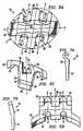
- edgewise bracket 10 of the present inventionis illustrated in Figs. 1A-C and 2A-D, with various modifications, modalities and an exemplary auxiliary reflected by Figs. 3A-C, 4A-C, 5A-C, 6A-C and 7A-B. Corresponding features are referenced by common reference numerals.
- the edgewise bracket 10comprises two integral, opposing T-shaped tie wings 12 and 14 having a common base portion and base surface 16, and defining an archwire slot 18 therebetween.
- a flange 32may be adjoined to the bracket 10 for subsequent attachment to a hand.
- the bracketmay be adjoined to a bonding pad (not shown).
- Each ligating support means 20 and 22Two sets of opposing ligating support means 20 and 22, are provided, each set comprising a gingivally disposed notch and occlusally disposed notch on the gingival and occlusal edges of tie wings 12,14, respectively.
- Each ligating support meanshas a sloped portion 24 and top land portion 26. The sloped portions 24 have concave, curvlinear surfaces.
- Each of the T-shaped tie wings 12,14comprises a cantilevered central leg portion 28 centered upon the gingival-occlusal center axis (lying within plane AA) of the bracket 10 and cantilevered mesial/distal wing tip portions 30, with the above-noted top land portions 26 integral therebetween.
- the gingival/occlusal extremes of the center leg 28 and mesial/distal wing tip portions 30 of the tie wings 12,14define, from the labial aspect, an elliptical configuration E.
- cantilevered wing tip portions 30extend a sufficient distance d outward from the outer sidewalls 34, 36 of the tie wings 12, 14, respectively, to retain a ligating device in an arcuate seat 38 formed under the cantilevered tie wing tip portions 30 and center legs 28.
- the cantilevered center leg 28 of each T-shaped tie wing 12, 14,extends a distance f beyond the outer gingival/occlusal extreme of the ligating support means 20 adjacent thereto, such distance f being at least approximately as great as the distance d.
- the sidewalls defining the archwire slot 18comprise two sets of opposing convex portions 42 to reduce frictional engagement with an archwire.
- the floor of archwire slot 18is provided with two convex portions 44 extending transversely across the archwire slot 18 to reduce frictional engagement with an archwire.
- the ligating support means 20, convex slot sidewall portions 42, and convex slot floor portion 44 disposed on the same side of the gingival-occlusal center plane AAmay have a common center axis (lying within plane BB).
- frictional engagement between an archwire and the slot walls and base, and between an archwire and ligating device supported on ligating support means 20occurs in a limited region about plane BB,
- An optional auxiliary slot 70may be provided to receive a complimentary auxiliary device, such as the exemplary auxiliary 74 illustrated in Figs. 7A and 7B.
- a complimentary auxiliary devicesuch as the exemplary auxiliary 74 illustrated in Figs. 7A and 7B.
- the inner sidewalls of auxiliary slot 70 and interfacing shaft portion 76 of the exemplary auxiliary 74are preferably configured to restrict rotational movement therebetween.
- a complimentary square-angled configurationmay be employed.
- the auxiliary 74preferably comprises an extending portion 78 having an outer configuration which will not fit into auxiliary slot 70, thereby facilitating placement and removal.
- Figs. 2A-Billustrate the interface between an archwire X and elastomeric ligating device Y when both sets of the ligating support means 20 of the embodiment of the present invention illustrated in Figs. 1A-C are utilized.
- Figs. 2C-Dillustrate the interface between an archwire X and elastomeric ligating device Y when neither of the ligating support means 20 of such embodiment are utilized.
- there are different treatment situationswhere each of these modalities may be desired.
- the provision of a set of ligating support means 20 on each of the mesial and distal sides of the bracket 10allows a practitioner to utilize one set but-not the other, as may be desirable.
- an integral T-shaped hook 50is provided as an extension to the center leg 28 of one of the T-shaped tie wings 12.
- the T-shaped hook 50preferably comprises flat lingual and labial surfaces (see Fig. 3C), and is preferably malleable to allow far pivotal movement relative to center leg 20.
- the T-shaped hook 50preferably comprises a tapered portion 52, arcuate neck portion 54 and head portion 56, whereby retention of a traction device in neck portion 54 is enhanced.
- Twin auxiliary slots 80may be optionally provided for receipt of an auxiliary device, such as the exemplary auxiliary 74 shown in Figs. 7A-B.
- the twin auxiliary slots 80are beneficially disposed under the convex slot floor portions 44.
- the configuration of slots 80 and exemplary auxiliary 74may be as described above to restrict rotational movement therebetween and facilitate placement/removal.
- Figs. 3A-Calso illustrate optional saddles 60 which can be provided in the support landing portions 26 for receiving a ligating device. It is believed that such saddles 60 may be beneficial in certain early treatment situations for purposes of retaining an undersized archwire in the desired position for rotational purposes.
- the outer sidewall 34 of tie wing 12 and outer sidewall 36 of tie wing 14define a trapezoid therebetween.
- outer side wall 34is angled relative to the longitudinal center plane CC of the archwire slot 18, and the outer tie wing sidewall 36 is disposed in parallel relation to the center plane CC of the archwire slot 18.
- the outer sidewall 34may be, for example, advantageously disposed gingivally on partially erupted upper bicuspids.
- bracket systems employed by this configurationwill generally reduce bracket/tooth contact between upper and lower arches.
- Figs. 4A-CThe modified embodiment illustrated in Figs. 4A-C is shown with additional features in Figs. 5A-C and 6A-C.
- a central auxiliary slot 70is provided in Figs. 5A-C.
- Figs 6A-Cillustrate the inclusion of twin auxiliary slots 80 for receiving of auxiliary devices.
- the twin vertical slots 80are disposed so that each passes under one of the convex slot floor portions 44.
- the gingival-occlusal canter axis of the bracket(lying within plane AA) can be disposed at an acute angle relative to center axis of archwire slot 18 (lying within plane CC). More particularly, center legs 28 may be centered upon the gingival-occlusal center axis and may be provided with distal/mesial surfaces 84 which are parallel to the gingival-occlusal center axis thereby facilitating placement of the bracket.
Landscapes
- Health & Medical Sciences (AREA)
- Oral & Maxillofacial Surgery (AREA)
- Dentistry (AREA)
- Epidemiology (AREA)
- Life Sciences & Earth Sciences (AREA)
- Animal Behavior & Ethology (AREA)
- General Health & Medical Sciences (AREA)
- Public Health (AREA)
- Veterinary Medicine (AREA)
- Dental Tools And Instruments Or Auxiliary Dental Instruments (AREA)
Description
- This invention generally relates to edgewiseorthodontic brackets and, more particularly, to edgewisebrackets having enhanced treatment, comfort and ease-of-usefeatures, as well as increased modalities.
- An orthodontic bracket as defined in the preamble of claim 1is disclosed in DE-U-8 903 611.
- Orthodontic brackets are widely used to align teeththrough the application of forces selectively provided byinterconnected archwires and accessories. Brackets aretypically of metal, ceramic or composite construction andare interconnected to either bands or bonding pads forattachment to teeth.
- In edgewise brackets, an archwire passes through alabially opening, horizontal slot defined by one or morepair of opposing tie wings. The archwire is pre-shaped andsized to provide the desired forces. In each bracket, atie wing pair includes a gingivally extending tie wing andocclusally extending tie wing. Once placed in the slot ofone or more pair of tie wings, an archwire is typicallyrestricted therein by a ligating device such as a steel orelastomeric ligature.
- As orthodontic treatment objectives and techniquescontinue to evolve, numerous corresponding edgewise bracketdesigns and interconnecting accessories have been proposed.Recently, it has been recognized that it is desirable toreduce frictional engagement between the archwire and bracket surfaces defining the archwire slot to facilitatespace closure and bodily tooth movement. Similarly, inmany situations, it is now a goal to reduce frictionalengagement between the archwire and ligating deviceemployed to restrict the archwire within the slot. Suchfriction reduction can markedly increase the rate of toothmovement and reduce the duration of the orthodontictreatment.
- At the same time, patient comfort and ease-of-useconsiderations have become increasingly important. Patientcomfort has been largely addressed by reducing bracket sizeto yield smaller and more smoothly contoured bracket.Ease-of-use considerations have stimulated bracket designswhich facilitate practitioner's bracket placement/use andaccommodate plural modalities.
- The present invention represents significant advancesin relation to the above-noted orthodontic bracketconsiderations, both singularly and combinatively, whilemaintaining the structural integrity of the bracket.
- In one aspect of the present invention, an edgewisebracket is provided having a pair of tie wings defining anarchwire slot therebetween, and a pair of ligating supportmeans, one defined within the mesial/distal extent of eachtie wing. The ligating support means may be selectivelyemployed to reduce frictional engagement between anarchwire positioned in the slot and a ligating device positioned on the ligating support means and across thearchwire slot. Each ligating support means includes asloped, or angled, portion that extends labially toward theslot (e.g., labially from the gingival/occlusal peripherytowards the slot), to reduce binding of a ligating devicepositioned thereupon. The ligating support means arenotches extending from the gingival or occlusalperiphery of a tie wing, sized to readily receive aligating device, and preferably having a curvlinear,concave configuration to further reduce binding.Typically, the opposing notches in a given pair of tiewings will have a common center axis which is parallel tothe gingival-occlusal center axis of the bracket. When thearchwire slot includes convex sidewall and/or floorportions to reduce archwire/bracket frictional engagement,the ligating support means are preferably disposed adjacentthereto (e.g., centered upon a common gingival-occlusalplane) for enhanced treatment control.
- In another aspect of the present invention, anedgewise bracket is provided having a single pair of tiewings and two pairs of opposing ligating support meansdefined within the mesial/distal extent of the tie wings,one pair on each of the mesial and distal sides of thebracket. The gingival/occlusal extremes of the tie wingsdefine an elliptical configuration when viewed labially.More particularly, each tie wing comprises central, mesialand distal portions which extend gingivally or occlusally,with ligating support means defined between the central and mesial portions and between the central and distalportions, wherein the gingival/occlusal edges of suchportions define an elliptical configuration. Suchconfiguration accommodates size reduction, yielding patientcomfort benefits, while preserving structural integrity andperformance.
- In this regard, and as will become apparent, a singlepair of opposing T-shaped tie wings is preferred. That is,the "caps" of the T-shaped tie wings define an archwireslot therebetween, and the "center legs" of each tie wingextends gingivally or occlusally. The ligating supportmeans are notches defined on thegingival/occlusal periphery on both the mesial and distalsides of a center leg of each T-shapedtie wing. Thecenter legs each comprise a gingivatly/occlusally extendingcantilevered portion that can be conveniently employed asa stanchion for ligature interconnection. Themesial/distal tie wing tip portions on the outside of eachnotch also comprise gingivally/occlusally extendingcantilevered portions that extend a sufficient distanceoutward from the outer tie wing sidewalls to retain aligating device in an arcuate seat formed wider thecantilevered tie wing tip portions and center legs duringconventional ligation. Relatedly, the cantilevered centerleg of each T-shaped tie wing should extend at leastapproximately the same distance outward beyond the outergingival/occlusal extremes of the adjacent ligating supportmeans so as to retain a ligating device when the ligating support notches are selectively employed by a practitionerto support a ligating device.
- In a further aspect of the present invention, anedgewise bracket is provided having a single pair of tiewings defining an archwire slot therebetween, and anintegral T-shaped hook extending gingivally/occlusally fromone tie wing, and in perpendicular relation to thelongitudinal center axis of the archwire slot, whereintraction devices (e.g., rubber bands, springs, etc.) can bereadily attached from a plurality of directions so as toaccommodate plural modalities for treatment. The T-shapedhook is centered upon the gingival-occlusal center axis ofthe bracket, and is preferably provided as a cantileveredextension of the center leg of a T-shaped tie wing so as tocommunicate external face moments created by interconnectedtraction devices close to a tooth's root center ofresistance. Preferably, the T-shaped hook is generallyflat as viewed from the mesial and distal aspects.Further, as viewed from the labial aspect, the T-shapedhook preferably comprises a tapered portion contiguous tothe center leg of the T-shaped tie wing, an arcuate neckportion contiguous thereto, and a head portion contiguousthereto the tapered portion, wherein a traction device maybe reliably maintained in the neck portion. That is, thetapered portion serves to restrict movement of the tractiondevice towards the archwire slot of the bracket, and thehead portion serves to restrict disconnection of thetraction device from the T-shaped hook. The integral T-shaped hook preferably comprises a malleable material so asto allow for selective pivotal movement of the T-shapedhook as may be desirable for soft tissue clearance andpatent comfort.
- In yet another aspect of the present invention, anedgewise bracket is provided having at least one pair oftie wings defining an archwire slot therebetween, whereinwhen viewed from mesial/distal aspects, thegingivally/occlusally facing outer sidewalls of the tiewing pair define a trapezoid. One outer sidewall isdisposed at an angle relative to the longitudinal centerplane of the archwire slot, wherein the sidewall extendslabially away from such center plane. The other sidewallis disposed substantially parallel to the archwire slotcenter plane. The angled sidewall is disposed gingivallyin maxillary applications and occlusally in mandibularapplications. By way of example, use of the describedconfiguration allows for enhanced, early treatment ofpartially erupted upper bicuspids, wherein the archwireslot will be acceptably, gingivally positioned upon fulleruption of the bicuspid. This enhances treatment andreduces demands upon the practitioner time. Further,bracket systems of this design will generally reducebracket/tooth contact between the upper and lower arches.Bracket profile and strength can also be acceptablymaintained using the described configuration.
- In another aspect of the present invention, anedgewise bracket is provided having one tie wing pair defining an archwire slot therebetween and at least oneauxiliary slot extending from a gingival edge to theocclusal edge, or vice versa, wherein the slot and shaft ofthe auxiliary device to be inserted into the slot havecomplimentary configurations to restrict rotationalmovement therebetween. By way of example, the auxiliaryslot may have adjoining flat inner sidewalls (e.g.,defining square corners), and the auxiliary shaft may havecomplimentary flat outer sidewalls (e.g., defining squarecorners), wherein rotational movement therebetween isdesirably restricted.
- In a related aspect of the present invention, anedgewise bracket is provided having a single tie wing pairdefining an archwire slot thereheween, at least one convexportion extending labially and transversely across thefloor of the archwire slot, and at least one auxiliary slotextending gingivally/occlusally and positioned under theconvex slot floor portion. By positioning the auxiliaryslot under the convex slat floor portion, bracket heightcan be advantageously conserved, and therefore reduced, soas to enhance patient comfort. When two convex slot floorportions are provided, one on each of the mesial/distalsides, twin auxiliary slots may be advantageouslypositioned so that one passes under each of the convex slotfloor portions. In addition to the above-noted advantages,this bracket yields significant tooth rotationcapabilities. For example, in early treatment stages, thetwin auxiliary slots can be utilized with a steel ligature to achieve rapid gross tooth rotation. As can beappreciated, complementary auxiliary slot/auxiliary shaftconfigurations of the above-described nature can also beemployed.
- In one embodiment of the a present invention, anedgewise bracket is provided having a single set ofopposing T-shaped tie wings with ligating support notchesdefined on each side (i.e., mesially and distally) of thecenter leg of each tie wing. The sidewalls defining thearchwire slot are provided to present two sets of opposingconvex sidewall portions, one set on each of the mesial anddistal sides of the bracket. Similarly, the floor of thearchwire slot is provided to present two convex portionsextending labially and transversely across the slot, one oneach of the mesial and distal sides of the bracket. Byvirtue of this arrangement, the bracket yields desirabletooth rotation and alignment capabilities with reducedarchwire/archwire slot frictional engagement andselectively reduced archwire/ligating device frictionalengagement. Further, this configuration defines a dynamicarchwire slot, wherein the archwire is allowed to maintaina "memory" of its slot entry angle, as is now desirable.The notches each comprise a portion that extends labiallyoutwardly from the gingival/occlusal periphery towards thearchwire slot and presents concave, curvlinear surfaces toreduce ligature binding. The gingival/occlusal edges ofthe center legs and wing tip portions of the opposing T-shapedtie wings define an elliptical configuration when viewed labially so as to reduce bracket size and advancepatient comfort/ appearance. All prominent edges exposedto soft tissue are preferably rounded for patient comfort.
- An integral T-shaped hook of the above-describednature may be optionally provided as a cantileveredgingival/occlusal extension of the center leg of either T-shapedtie wing. The T-shaped hook preferably comprises amalleable material and preferably comprises flat linguallyand labially facing surfaces, wherein the hook can bemanually pivoted to a limited extent by a practitionerrelative to the center leg of the tie wing.
- An auxiliary slot may also be optionally provided anddisposed within the gingival-occlusal center plane of thebracket, underlying the center leg portions of the opposingT-shaped tie wings. Alternatively, twin auxiliary slotsmay be provided, one on each side of the gingival-occlusalcenter plane of the bracket (i.e., mesially and distallypositioned), such slots passing under the mesial and thedistal convex slot floor portions of the archwire slot.Whether a single or twin auxiliary slot arrangement isprovided, each slot preferably has an inner-configurationwhich will restrict rotation of complimentary auxiliariesinserted thereto, as described above.
- The T-shaped tie wings of the bracket may also beoptionally defined so that the outer gingival/occlusalfacing sidewalls of the tie wing pair define a trapezoidwhen viewed from the mesial or distal aspects. Moreparticularly, one of the outer sidewalls is disposed at an angle relative to the longitudinal center plane of thearchwire slot, and is perpendicular to the tie wing basesurface or base/bottom surface of the bracket. The otherouter sidewall is disposed in parallel relation to thecenter plane of the archwire slot.
- The center leg of each T-shaped tie wing may also beoptionally disposed at an acute angle relative to thelongitudinal center axis of the slot. Such angling may bedesired in applications wherein the central axis of theclinical crown is positioned at an acute angle relative tothe ooclusal plane in normal occlusion. Such anglingcorrespondingly facilitates the practitioner's placement ofthe bracket on a tooth, wherein the axes of the center legsmay be disposed along a tooth long axis, and wherein thecenter axis of the bracket slot may be disposed parallel tothe occlusal plane. Preferably, the mesial/distal facingedges of the center leg of each T-shaped tie wing are alsoparallel to the axes of the center legs to furtherfacilitate accurate placement on a tooth. It is alsopreferable for the center axes of opposing ligating supportnotches to be disposed parallel to the gingival-occlusalcenter plane of the bracket. Relatedly, for rotationalpurposes, it is preferable for the apices of the opposingconvex slot sidewall portions and a convex slot floorportion correspondingly positioned on the same mesial ordistal side to lie within a common plane that is disposedsubstantially perpendicular to the longitudinal centerplane of the archwire slot.
- As will be appreciated by those skilled in the art,the embodiment of the invention described herein yieldsnumerous advantageous features, yielding a new state-of-the-artbracket.
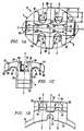
- Figs. 1A-C illustrate labial, side and end views ofone embodiment of the present invention;
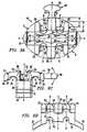
- Figs. 2A and 2B, and Figs. 2C and 2D, illustratelabial and end views of the embodiment of Figs. 1A-C whenligating support means are employed to support anelastomeric ligature and when ligating support means arenot employed to support an elastomeric ligature,respectively;
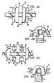
- Figs. 3A-C illustrate labial, aide and end views of amodified version of said embodiment of the presentinvention having an integral T-shaped hook and twinauxiliary slots;
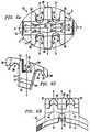
- Figs. 4A-C illustrate labial, side and end views of amodified version of said embodiment of the presentinvention having outer tie wing sidewalls that define atrapezoid therebetween;
- Figs. 5A-D illustrate labial, side and end views ofthe modified embodiment of the present inventionillustrated in Figs. 4A-C, with a central auxiliary slot;
- Figs. 6A-C illustrate labial, side and opposing endviews of the modified embodiment of the present invention illustrated in Figs. 4A-C, with an angulated gingival-occlusalcenter axis and twin auxiliary slots; and,
- Figs. 7A-B illustrate two views of an exemplaryauxiliary device useable with the auxiliary slots of thepresent invention.
- One embodiment of the
edgewise bracket 10 of thepresent invention is illustrated in Figs. 1A-C and 2A-D,with various modifications, modalities and an exemplaryauxiliary reflected by Figs. 3A-C, 4A-C, 5A-C, 6A-C and 7A-B.Corresponding features are referenced by commonreference numerals. - The
edgewise bracket 10 comprises two integral,opposing T-shapedtie wings base surface 16, and defining anarchwire slot 18 therebetween. By way of example only, aflange 32 maybe adjoined to thebracket 10 for subsequent attachment toa hand. Alternatively, the bracket may be adjoined to abonding pad (not shown). - Two sets of opposing ligating support means 20 and 22,are provided, each set comprising a gingivally disposednotch and occlusally disposed notch on the gingival andocclusal edges of
tie wings portion 24 andtop landportion 26. Thesloped portions 24 have concave,curvlinear surfaces. - Each of the T-shaped
tie wings central leg portion 28 centered upon thegingival-occlusal center axis (lying within plane AA) ofthebracket 10 and cantilevered mesial/distalwing tipportions 30, with the above-notedtop land portions 26integral therebetween. The gingival/occlusal extremes ofthecenter leg 28 and mesial/distalwing tip portions 30 ofthetie wings wing tip portions 30 extend a sufficient distance d outwardfrom theouter sidewalls tie wings arcuateseat 38 formed under the cantilevered tiewing tip portions 30 andcenter legs 28. Relatedly, the cantileveredcenterleg 28 of each T-shapedtie wing - The sidewalls defining the
archwire slot 18 comprisetwo sets of opposingconvex portions 42 to reducefrictional engagement with an archwire. Similarly, thefloor ofarchwire slot 18 is provided with twoconvexportions 44 extending transversely across thearchwire slot 18 to reduce frictional engagement with an archwire. Asillustrated in Figs. 1A-C, the ligating support means 20,convexslot sidewall portions 42, and convexslot floorportion 44 disposed on the same side of the gingival-occlusal center plane AA may have a common center axis(lying within plane BB). As such, frictional engagementbetween an archwire and the slot walls and base, andbetween an archwire and ligating device supported onligating support means 20 occurs in a limited region aboutplane BB, - An optional
auxiliary slot 70 may be provided toreceive a complimentary auxiliary device, such as theexemplary auxiliary 74 illustrated in Figs. 7A and 7B. Theinner sidewalls ofauxiliary slot 70 and interfacingshaftportion 76 of theexemplary auxiliary 74 are preferablyconfigured to restrict rotational movement therebetween.As illustrated, a complimentary square-angled configurationmay be employed. Additionally, the auxiliary 74 preferablycomprises an extendingportion 78 having an outerconfiguration which will not fit intoauxiliary slot 70,thereby facilitating placement and removal. - Figs. 2A-B illustrate the interface between anarchwire X and elastomeric ligating device Y when both setsof the ligating support means 20 of the embodiment of thepresent invention illustrated in Figs. 1A-C are utilized.Figs. 2C-D illustrate the interface between an archwire Xand elastomeric ligating device Y when neither of theligating support means 20 of such embodiment are utilized.As will be appreciated by those in the art, there aredifferent treatment situations where each of thesemodalities may be desired. Additionally, the provision ofa set of ligating support means 20 on each of the mesial and distal sides of the
bracket 10 allows a practitioner toutilize one set but-not the other, as may be desirable. - In Figs. 3A-C an integral T-shaped
hook 50 is providedas an extension to thecenter leg 28 of one of the T-shapedtie wings 12. The T-shapedhook 50 preferably comprisesflat lingual and labial surfaces (see Fig. 3C), and ispreferably malleable to allow far pivotal movement relativeto centerleg 20. The T-shapedhook 50 preferably comprisesa tapered portion 52,arcuate neck portion 54 andheadportion 56, whereby retention of a traction device inneckportion 54 is enhanced. - Twin
auxiliary slots 80 may be optionally provided forreceipt of an auxiliary device, such as theexemplaryauxiliary 74 shown in Figs. 7A-B. The twinauxiliary slots 80 are beneficially disposed under the convexslot floorportions 44. The configuration ofslots 80 and exemplaryauxiliary 74 may be as described above to restrictrotational movement therebetween and facilitateplacement/removal. - Figs. 3A-C also illustrate
optional saddles 60 whichcanbe provided in thesupport landing portions 26 forreceiving a ligating device. It is believed thatsuchsaddles 60 may be beneficial in certain early treatmentsituations for purposes of retaining an undersized archwirein the desired position for rotational purposes. - In Figs. 4A-D, the
outer sidewall 34 oftie wing 12andouter sidewall 36 oftie wing 14 define a trapezoidtherebetween. Specificallyouter side wall 34 is angled relative to the longitudinal center plane CC of thearchwire slot 18, and the outertie wing sidewall 36 isdisposed in parallel relation to the center plane CC of thearchwire slot 18. By virtue of this arrangement, theoutersidewall 34 may be, for example, advantageously disposedgingivally on partially erupted upper bicuspids. Further,bracket systems employed by this configuration willgenerally reduce bracket/tooth contact between upper andlower arches. - The modified embodiment illustrated in Figs. 4A-C isshown with additional features in Figs. 5A-C and 6A-C. InFigs. 5A-C, a central
auxiliary slot 70 is provided. Figs6A-C illustrate the inclusion of twinauxiliary slots 80for receiving of auxiliary devices. The twinverticalslots 80 are disposed so that each passes under one of theconvexslot floor portions 44. - In the version shown in Figs. 6A-C, it should also beappreciated that the gingival-occlusal canter axis of thebracket (lying within plane AA) can be disposed at an acuteangle relative to center axis of archwire slot 18 (lyingwithin plane CC). More particularly,
center legs 28 may becentered upon the gingival-occlusal center axis and may beprovided with distal/mesial surfaces 84 which are parallelto the gingival-occlusal center axis thereby facilitatingplacement of the bracket. In this modified version, itshould be recognized that while the center plane BB of theligating support means 20 is also disposed parallel to thegingival-occlusal center axis, the apices of the convexslot sidewall portions 42 and convex slot floor portion oneach of mesial and distal sides lie in a plane which isperpendicular to the archwire slot center plane CC.Relatedly, it should be appreciated that, when a T-shapedhook is utilised (such as the T-shapedhook 50 illustratedin Figs. 3A-C above), the center axis thereof will bedisposed perpendicularly to the center axis of thearchwire slot 18 and at an angle relative to the gingival-occlusalcenter axis of thebracket 10. - The foregoing description of the present inventionhas been provided for purposes of illustration anddescription. This description is not intended to limitthe invention and various modalities thereof. Variations,embodiments and modifications will be apparent to thoseskilled in the art and are intended to be within the scopeof the following claims.
Claims (7)
- An edgewise orthodontic bracket (10) comprising:gingival and occlusal tie wings (12, 14) defining alabially opening archwire slot (18) therebetween, each ofthe gingival and occlusal tie wings (12, 14) having amesial/distal extent;said bracket (10) alsocomprises a first set of gingival and occlusal notches(20), the gingival notch being disposed within themesial/distal extent of said gingival tie wing (12) andthe occlusal notch being disposed within the mesial/distalextent of said occlusal tie wing (14);characterised by
a first set of opposing convex sidewall portions (42)within said archwire slot (18), wherein said first set ofconvex sidewall portions (42) is positioned substantiallybetween said gingival and occlusal notches of said firstset of notches (20). - An edgewise orthodontic bracket according to Claim 1,further comprising:a second set of gingival and occlusal notches (22),the gingival notch being disposed within the mesial/distalextent of said gingival tie wing (12) and the occlusalnotch being disposed within the mesial/distal extent ofsaid occlusal tie wing (14);said first set of gingival and occlusal notches (20)being disposed on a mesial side of said bracket (10), andsaid second set of gingival and occlusal notches (22)being disposed on a distal side of said bracket (10);a second set of opposing convex sidewall portions(42) within said archwire slot (18), wherein said secondset of convex sidewall portions (42) is positioned substantially between said gingival and occlusal notchesof said second set of notches (22).
- An edgewise orthodontic bracket according to Claim 1or 2, wherein said gingival notch includes a slopedportion extending labially toward the archwire slot, andsaid occlusal notch includes a sloped portion extendinglabially towards the archwire slot.
- An edgewise orthodontic bracket according to anypreceding claim, wherein said gingival notch furthercomprises a concave notch extending from a gingival edgeof said gingival tie wing towards said archwire slot, andwherein said occlusal notch further comprises a concavenotch extending from an occlusal edge of said occlusal tiewing toward said archwire slot.
- An edgewise orthodontic bracket according to anypreceding claim, wherein:wherein said gingivally-extending center leg (28)extends a greater distance (F) from said archwire slot(18) than each of said gingivally-extending mesial anddistal tie wing tip portions (30), and said occlusally-extendingcenter leg (28) extends a greater distance (F)from said archwire slot (18) than each of said occlusally-extendingmesial and distal tie wing tip portions (30).said gingival tie wing (12) further comprises agingivally-extending center leg portion (28) andgingivally-extending mesial and distal tie wing tipportions (30) ;said occlusal tie wing (14) further comprises anocclusally-extending center leg portion (28) andocclusally-extending mesial and distal tie wing tipportions (30); and
- An edgewise orthodontic bracket according to Claim 2or to any of Claims 3 to 5 when dependent from Claim 2,comprising:a first convex floor portion (44) within saidarchwire slot (18), positioned substantially between saidfirst set of gingival and occlusal notches (20); anda second convex floor portion (44) within saidarchwire slot (18), positioned substantially between saidsecond set of gingival and occlusal notches (22).
- An edgewise orthodontic bracket according to anypreceding claim, wherein gingival edges of said gingivaltie wing and occlusal edges of said occlusal tie wingdefine an elliptical configuration.
Applications Claiming Priority (3)
| Application Number | Priority Date | Filing Date | Title |
|---|---|---|---|
| US07/702,943US5160261A (en) | 1991-05-20 | 1991-05-20 | Orthodontic bracket and method |
| US702943 | 1991-05-20 | ||
| EP92914262AEP0588961B1 (en) | 1991-05-20 | 1992-05-20 | Improved edgewise orthodontic bracket |
Related Parent Applications (1)
| Application Number | Title | Priority Date | Filing Date |
|---|---|---|---|
| EP92914262ADivisionEP0588961B1 (en) | 1991-05-20 | 1992-05-20 | Improved edgewise orthodontic bracket |
Publications (3)
| Publication Number | Publication Date |
|---|---|
| EP0875211A2 EP0875211A2 (en) | 1998-11-04 |
| EP0875211A3 EP0875211A3 (en) | 2002-02-13 |
| EP0875211B1true EP0875211B1 (en) | 2003-10-01 |
Family
ID=24823260
Family Applications (2)
| Application Number | Title | Priority Date | Filing Date |
|---|---|---|---|
| EP98202610AExpired - LifetimeEP0875211B1 (en) | 1991-05-20 | 1992-05-20 | Improved edgewise orthodontic bracket |
| EP92914262AExpired - LifetimeEP0588961B1 (en) | 1991-05-20 | 1992-05-20 | Improved edgewise orthodontic bracket |
Family Applications After (1)
| Application Number | Title | Priority Date | Filing Date |
|---|---|---|---|
| EP92914262AExpired - LifetimeEP0588961B1 (en) | 1991-05-20 | 1992-05-20 | Improved edgewise orthodontic bracket |
Country Status (6)
| Country | Link |
|---|---|
| US (2) | US5160261A (en) |
| EP (2) | EP0875211B1 (en) |
| JP (1) | JP2579431B2 (en) |
| DE (2) | DE69228472T2 (en) |
| ES (2) | ES2130174T3 (en) |
| WO (1) | WO1992020296A1 (en) |
Cited By (14)
| Publication number | Priority date | Publication date | Assignee | Title |
|---|---|---|---|---|
| US7247018B2 (en) | 2002-10-29 | 2007-07-24 | Rmo, Inc. | Edgewise orthodontic bracket with character base |
| US7695277B1 (en) | 2004-10-28 | 2010-04-13 | Rmo, Inc. | Orthodontic bracket with frangible cover mechanism |
| US7959437B2 (en) | 2002-10-29 | 2011-06-14 | Rmo, Inc. | Orthodontic appliance with encoded information formed in the base |
| USD660436S1 (en) | 2011-05-13 | 2012-05-22 | Rmo, Inc. | Orthodontic bracket |
| USD660435S1 (en) | 2011-05-13 | 2012-05-22 | Rmo, Inc. | Orthodontic bracket |
| USD660968S1 (en) | 2011-05-13 | 2012-05-29 | Rmo, Inc. | Orthodontic bracket |
| US8251697B2 (en) | 2006-09-07 | 2012-08-28 | Rmo, Inc. | Reduced-friction buccal tube and method of use |
| US8376739B2 (en) | 2011-05-12 | 2013-02-19 | Rmo, Inc. | Self ligating orthodontic bracket having a rotatable member |
| US8485816B2 (en) | 2009-03-16 | 2013-07-16 | Rmo, Inc. | Orthodontic bracket having an archwire channel and archwire retaining mechanism |
| USD721811S1 (en) | 2013-10-29 | 2015-01-27 | Rmo, Inc. | Orthodontic bracket |
| US8979528B2 (en) | 2006-09-07 | 2015-03-17 | Rmo, Inc. | Customized orthodontic appliance method and system |
| USD726318S1 (en) | 2013-01-17 | 2015-04-07 | Rmo, Inc. | Dental instrument for a self-ligating orthodontic clip |
| US9554875B2 (en) | 2006-09-07 | 2017-01-31 | Rmo, Inc. | Method for producing a customized orthodontic appliance |
| USD847349S1 (en) | 2011-09-22 | 2019-04-30 | Rmo, Inc. | Orthodontic lock with flange |
Families Citing this family (56)
| Publication number | Priority date | Publication date | Assignee | Title |
|---|---|---|---|---|
| JPH03176043A (en)* | 1989-12-05 | 1991-07-31 | Hajime Suyama | Bracket for rectification of dental arch |
| JPH0639689Y2 (en)* | 1991-01-28 | 1994-10-19 | ホーヤ株式会社 | Orthodontic bracket |
| US5160261A (en)* | 1991-05-20 | 1992-11-03 | Rmo, Inc. | Orthodontic bracket and method |
| US5302121A (en)* | 1992-06-30 | 1994-04-12 | Gagin William P | Ball-in-socket orthodontic bracket |
| US5282743A (en)* | 1992-12-24 | 1994-02-01 | Gac International, Inc. | Orthodontic bracket |
| EP0714639B1 (en)* | 1994-11-29 | 2001-08-08 | Sankin Kogyo Kabushiki Kaisha | Orthodontic bracket |
| US5782631A (en)* | 1996-12-11 | 1998-07-21 | Kesling; Christopher K. | Orthodontic appliance |
| US5873716A (en)* | 1997-05-06 | 1999-02-23 | Tp Orthodontics, Inc. | Orthodontic hook assembly and appliance |
| ES2143404B1 (en)* | 1998-03-16 | 2000-12-16 | Izquierdo Vicente Olmos | BRACKETS FOR DENTAL HOLDING. |
| DE19812184A1 (en) | 1998-03-19 | 1999-09-23 | Norbert Abels | Orthodontic fixture element with base and holder |
| WO1999058078A1 (en)* | 1998-05-11 | 1999-11-18 | 3M Innovative Properties Company | Orthodontic bracket with tie wing reinforcement members |
| US5993207A (en)* | 1998-10-06 | 1999-11-30 | Spencer; William A. | Orthodontic accessory for corrective force application to orthodontic bracket |
| DE10011596B4 (en) | 2000-03-10 | 2007-12-27 | Norbert Dr. Abels | Orthodontic bracket |
| US6478579B1 (en) | 2000-08-29 | 2002-11-12 | Rmo, Inc. | Orthodontic twin bracket with archwire floor and side wall relief |
| US6394798B1 (en) | 2000-08-31 | 2002-05-28 | Ortho Organizers | Unitary metal injection molded orthodontic bracket |
| WO2002064051A1 (en) | 2001-02-15 | 2002-08-22 | Norbert Abels | Self-ligating orthodontic brackets having a rigid bracket base and deformable ligation cover |
| ATE299356T1 (en) | 2001-02-15 | 2005-07-15 | Norbert Abels | SELF CLAMPING ORTHODONTIC BRACKETS WITH SAFETY LOCKING FEATURE FOR LIGATURE COVERS |
| US6932597B2 (en)* | 2001-09-12 | 2005-08-23 | Norbert Abels | Self-ligating orthodontic brackets including a metal ligation cover hingedly connected to a bracket base |
| US6960081B2 (en)* | 2003-03-04 | 2005-11-01 | Norbert Abels | Orthodontic brackets with elongate film hinge |
| US6960080B2 (en)* | 2003-03-04 | 2005-11-01 | Norbert Abels | Orthodontic brackets with elongate film hinge |
| JP4110030B2 (en)* | 2003-04-18 | 2008-07-02 | 三栄源エフ・エフ・アイ株式会社 | Method for suppressing film formation of liquid food |
| ITPD20030278A1 (en)* | 2003-11-20 | 2005-05-21 | Valter Vigolo | SELF-LOCKING ORTHODONTIC ATTACK AND METHOD |
| US7192274B2 (en) | 2003-12-08 | 2007-03-20 | 3M Innovative Properties Company | Ceramic orthodontic appliance with archwire slot liner |
| US6964565B2 (en)* | 2004-02-19 | 2005-11-15 | Norbert Abels | Two-part orthodontic bracket |
| US20080138756A1 (en)* | 2004-04-01 | 2008-06-12 | Innobrace Orthodontics Pte Ltd | Orthondontic Bracket With Mesial And Distal Tie Wing Undercuts |
| US7033170B2 (en)* | 2004-05-11 | 2006-04-25 | Mark Andrew Cordato | Orthodontic bracket and clip |
| DE102004056167A1 (en)* | 2004-11-18 | 2006-06-01 | Bernhard Förster Gmbh | Self-ligating bracket for orthodontics |
| US20060199137A1 (en)* | 2005-03-04 | 2006-09-07 | Norbert Abels | Orthodontic retainer system with removable retaining wire |
| JP2006314456A (en)* | 2005-05-11 | 2006-11-24 | Masahiro Denpo | Orthodontic bracket |
| US20060263737A1 (en)* | 2005-05-20 | 2006-11-23 | Ormco Corporation | Orthodontic brackets and appliances and methods of making and using orthodontic brackets |
| US20070224568A1 (en)* | 2006-03-27 | 2007-09-27 | Fu-Yi Lin | Tooth orthopedic appliance |
| US20080160474A1 (en)* | 2006-03-31 | 2008-07-03 | Rmo, Inc. | Orthodontic Bracket With Lined Archwire Slot and Slot Cover |
| JP2009535124A (en)* | 2006-04-26 | 2009-10-01 | アールエムオー,インコーポレイテツド | Orthodontic bracket with removable slot cover |
| NL1032154C2 (en) | 2006-07-12 | 2008-01-15 | Janalt Damstra | Orthodontic bracket of twin type involves method for retention of curved thread or wire in groove in bracket, with thread or wire enclosed in appropriately formed component |
| US20080241782A1 (en)* | 2007-03-30 | 2008-10-02 | Norbert Abels | Two-part self-ligating orthodontic bracket having lateral guiding mechanism |
| US7857618B2 (en)* | 2007-11-27 | 2010-12-28 | Ultradent Products, Inc. | Orthodontic bracket including mechanism for reducing slot width for early torque control |
| US20100015565A1 (en)* | 2008-06-13 | 2010-01-21 | Roberto J. Carrillo Gonzalez | Orthodontic Devices |
| CN104146787B (en) | 2008-08-13 | 2017-06-23 | 奥姆科公司 | For the orthodontic bracket that arch wire is coupled with tooth |
| US7963768B2 (en)* | 2008-09-05 | 2011-06-21 | Jack Keith Hilliard | Self-ligating orthodontic bracket assembly |
| AU2009238317B2 (en) | 2008-11-14 | 2011-10-06 | Ormco Corporation | Surface treated polycrystalline ceramic orthodontic bracket and method of making same |
| US11219507B2 (en) | 2009-03-16 | 2022-01-11 | Orthoamerica Holdings, Llc | Customized orthodontic appliance and method |
| US20100323315A1 (en)* | 2009-06-23 | 2010-12-23 | Kyoto Takemoto | Orthodontic bracket |
| US9345558B2 (en) | 2010-09-03 | 2016-05-24 | Ormco Corporation | Self-ligating orthodontic bracket and method of making same |
| CN101947138B (en) | 2010-09-10 | 2012-08-29 | 广州瑞通生物科技有限公司 | General lingual bracket system |
| US8622738B2 (en)* | 2010-12-14 | 2014-01-07 | Michael Stuart Johnston | Orthodontic brace system and method |
| US8834156B2 (en)* | 2011-05-16 | 2014-09-16 | Ortho Organizers, Inc. | Orthodontic bracket system |
| US8678817B2 (en)* | 2011-09-16 | 2014-03-25 | Clarke John Stevens | Orthodontic bracket with slot base |
| WO2013055529A1 (en)* | 2011-10-10 | 2013-04-18 | 3M Innovative Properties Company | Orthodontic appliances with tapered archwire slots |
| US20140370455A1 (en)* | 2012-08-05 | 2014-12-18 | Timothy J. Allesee | Passive Active Ligation System for Orthodontic Brackets |
| EP2881076B1 (en) | 2013-12-06 | 2019-07-31 | 3M Innovative Properties Company | Labial attachment device for use with orthodontic auxiliary and lingual appliance system |
| US10039618B2 (en) | 2015-09-04 | 2018-08-07 | Ormco Corporation | Orthodontic brackets |
| TR201512157A2 (en) | 2015-10-02 | 2016-02-22 | Babacan Hasan | LOW FRICTION BRACKET |
| WO2017213594A1 (en)* | 2016-06-07 | 2017-12-14 | Panchaphongsaphak Thanapon | Orthodontic bracket |
| DE102017128418A1 (en)* | 2017-11-30 | 2019-06-06 | Swissodont Gmbh | bracket |
| CN110584810B (en)* | 2019-09-25 | 2024-10-11 | 广州欧欧医疗科技有限责任公司 | A buccal tube with hidden traction hook |
| WO2022149083A1 (en)* | 2021-01-08 | 2022-07-14 | 3M Innovative Properties Company | Prescription attachments for removable dental appliances |
Family Cites Families (41)
| Publication number | Priority date | Publication date | Assignee | Title |
|---|---|---|---|---|
| US1890487A (en)* | 1930-06-05 | 1932-12-13 | Edward H Angle | Orthodontic appliance |
| US3435527A (en)* | 1968-02-19 | 1969-04-01 | Peter C Kesling | Safety lock pin |
| US3854207A (en)* | 1973-08-13 | 1974-12-17 | Silverado Industries | Orthodontic bracket with spring clip retainer means |
| US4386908A (en)* | 1976-11-15 | 1983-06-07 | Kurz Craven H | Lingual orthodontic appliance system for the mandibular arch |
| US4103423A (en)* | 1977-03-04 | 1978-08-01 | Kessel Stanley P | Orthodontic bracket |
| US4103432A (en)* | 1977-05-06 | 1978-08-01 | Dieterich Frank L | Vegetable drying apparatus |
| FR2497657A2 (en)* | 1978-05-18 | 1982-07-16 | Nodiot Henri | Orthodontic brace using cross grooved support - has attached vestibular tooth face together with bolt securing wire of bi-tubular form |
| US4193195A (en)* | 1978-07-20 | 1980-03-18 | American Orthodontics Corporation | Orthodontic appliance |
| US4219617A (en)* | 1978-08-09 | 1980-08-26 | Melvin Wallshein | Ceramic orthodontic bracket |
| US4242085A (en)* | 1978-11-13 | 1980-12-30 | Melvin Wallshein | Multi-purpose orthodontic bracket |
| US4260375A (en)* | 1979-12-13 | 1981-04-07 | Melvin Wallshein | Bent wire orthodontic spring clip |
| US4529975A (en)* | 1981-11-06 | 1985-07-16 | Michael Hung | Separate overload detecting and warning system for hydraulic jack |
| US4529382A (en)* | 1982-04-19 | 1985-07-16 | Creekmore Thomas D | Lingual orthodontic appliance system for edgewise therapy |
| US4669981A (en)* | 1982-09-20 | 1987-06-02 | Kurz Craven H | Lingual orthodontic appliance system |
| DE3308104C2 (en)* | 1983-03-08 | 1996-07-18 | Foerster Bernhard Gmbh | Clamping and / or holding device for orthodontic purposes |
| US4478577A (en)* | 1983-08-09 | 1984-10-23 | Warren Jr Richard F | Orthodontic appliance |
| US4498867A (en)* | 1984-01-31 | 1985-02-12 | Tp Laboratories, Inc. | Convertible orthodontic appliance |
| US4527975A (en)* | 1984-03-19 | 1985-07-09 | Joseph Ghafari | Cosmetic orthodontic device |
| EP0161831B1 (en) | 1984-04-23 | 1996-03-06 | JOHNSON & JOHNSON DENTAL PRODUCTS COMPANY | Crystalline alumina orthodontic bracket |
| CA1284040C (en)* | 1986-06-26 | 1991-05-14 | Peter C. Kesling | Edgewise bracket to provide both free crown tipping and a predetermineddegree of root uprighting |
| US4712999A (en)* | 1986-09-10 | 1987-12-15 | Farel Rosenberg | Convertible, self-ligating, archwire positioning orthodontic bracket |
| US5161969A (en)* | 1986-09-29 | 1992-11-10 | Minnesota Mining And Manufacturing Company | Orthodontic bracket |
| US4859179A (en)* | 1986-11-26 | 1989-08-22 | Tp Orthodontics, Inc. | Edgewise bracket with Sved shaped slot and control means |
| US4820151A (en)* | 1987-05-08 | 1989-04-11 | Unitek Corporation | Orthodontic bracket |
| US4819316A (en)* | 1987-07-29 | 1989-04-11 | Rmo, Inc. | Method of making a pre-adjusted orthodontic bracket assembly |
| US4793804A (en)* | 1987-09-14 | 1988-12-27 | Schudy George F | Orthodontic bracket |
| US4799882A (en)* | 1987-11-17 | 1989-01-24 | Tp Orthodontics, Inc. | Edgewise bracket |
| US4917602A (en)* | 1988-09-12 | 1990-04-17 | Broussard Garfford J | Adjustable orthodontic bracket assembly |
| JPH02198545A (en)* | 1989-01-26 | 1990-08-07 | Hajime Suyama | Orthodontic bracket |
| AU5134190A (en)* | 1989-03-20 | 1990-09-20 | Johnson & Johnson Consumer Products, Inc. | Improved dental bracket configuration |
| DE8903611U1 (en)* | 1989-03-22 | 1990-07-19 | Bernhard Förster GmbH, 7530 Pforzheim | Orthodontic device in the form of a bracket |
| CA2016249A1 (en)* | 1989-05-12 | 1990-11-12 | Kozo Kawaguchi | Orthodontic appliance with hook |
| JPH0642655Y2 (en)* | 1989-05-12 | 1994-11-09 | トミー株式会社 | Orthodontic bracket with hook |
| JPH0681622B2 (en)* | 1989-06-20 | 1994-10-19 | トミー株式会社 | Orthodontic bracket |
| JPH03176043A (en)* | 1989-12-05 | 1991-07-31 | Hajime Suyama | Bracket for rectification of dental arch |
| US5127828A (en)* | 1989-12-05 | 1992-07-07 | Jobert Suzanne | Orthodontic appliance |
| US5125831A (en)* | 1990-11-02 | 1992-06-30 | Minnesota Mining And Manufacturing Company | Orthodontic bracket with bi-directional hook |
| US5154607A (en)* | 1991-05-13 | 1992-10-13 | Herbert Hanson | Low friction orthodontic brackets |
| US5160261A (en)* | 1991-05-20 | 1992-11-03 | Rmo, Inc. | Orthodontic bracket and method |
| DE4118248C2 (en)* | 1991-06-04 | 1998-09-24 | Foerster Bernhard Gmbh | Orthodontic device |
| US5322435A (en)* | 1992-07-23 | 1994-06-21 | Pletcher Erwin Carroll | Orthodontic bracket |
- 1991
- 1991-05-20USUS07/702,943patent/US5160261A/ennot_activeExpired - Lifetime
- 1992
- 1992-05-20EPEP98202610Apatent/EP0875211B1/ennot_activeExpired - Lifetime
- 1992-05-20EPEP92914262Apatent/EP0588961B1/ennot_activeExpired - Lifetime
- 1992-05-20ESES92914262Tpatent/ES2130174T3/ennot_activeExpired - Lifetime
- 1992-05-20DEDE69228472Tpatent/DE69228472T2/ennot_activeExpired - Lifetime
- 1992-05-20ESES98202610Tpatent/ES2206827T3/ennot_activeExpired - Lifetime
- 1992-05-20DEDE69233224Tpatent/DE69233224T2/ennot_activeExpired - Lifetime
- 1992-05-20JPJP5500286Apatent/JP2579431B2/ennot_activeExpired - Lifetime
- 1992-05-20WOPCT/US1992/004263patent/WO1992020296A1/enactiveIP Right Grant
- 1993
- 1993-05-12USUS08/060,879patent/US5470228A/ennot_activeExpired - Lifetime
Cited By (22)
| Publication number | Priority date | Publication date | Assignee | Title |
|---|---|---|---|---|
| US7959437B2 (en) | 2002-10-29 | 2011-06-14 | Rmo, Inc. | Orthodontic appliance with encoded information formed in the base |
| US9597166B2 (en) | 2002-10-29 | 2017-03-21 | Rmo, Inc. | Orthodontic appliance with encoded information |
| US7247018B2 (en) | 2002-10-29 | 2007-07-24 | Rmo, Inc. | Edgewise orthodontic bracket with character base |
| US8573971B2 (en) | 2004-10-28 | 2013-11-05 | Rmo, Inc. | Orthodontic bracket with frangible cover mechanism |
| US7695277B1 (en) | 2004-10-28 | 2010-04-13 | Rmo, Inc. | Orthodontic bracket with frangible cover mechanism |
| US8979528B2 (en) | 2006-09-07 | 2015-03-17 | Rmo, Inc. | Customized orthodontic appliance method and system |
| US9554875B2 (en) | 2006-09-07 | 2017-01-31 | Rmo, Inc. | Method for producing a customized orthodontic appliance |
| US9561089B2 (en) | 2006-09-07 | 2017-02-07 | Rmo, Inc. | Reduced-friction buccal tube and method of use |
| US8251697B2 (en) | 2006-09-07 | 2012-08-28 | Rmo, Inc. | Reduced-friction buccal tube and method of use |
| US8807997B2 (en) | 2006-09-07 | 2014-08-19 | Rmo, Inc. | Reduced-friction buccal tube and method of use |
| US8585399B2 (en) | 2006-09-07 | 2013-11-19 | Rmo, Inc. | Reduced-friction buccal tube and method of use |
| US9144473B2 (en) | 2009-03-16 | 2015-09-29 | Rmo, Inc. | Orthodontic bracket having an archwire channel and archwire retaining mechanism |
| US8485816B2 (en) | 2009-03-16 | 2013-07-16 | Rmo, Inc. | Orthodontic bracket having an archwire channel and archwire retaining mechanism |
| US8678818B2 (en) | 2011-05-12 | 2014-03-25 | Rmo, Inc. | Self ligating orthodontic bracket having a rotatable member |
| US8961172B2 (en) | 2011-05-12 | 2015-02-24 | Rmo, Inc. | Self ligating orthodontic bracket having a rotatable member |
| US8376739B2 (en) | 2011-05-12 | 2013-02-19 | Rmo, Inc. | Self ligating orthodontic bracket having a rotatable member |
| USD660968S1 (en) | 2011-05-13 | 2012-05-29 | Rmo, Inc. | Orthodontic bracket |
| USD660435S1 (en) | 2011-05-13 | 2012-05-22 | Rmo, Inc. | Orthodontic bracket |
| USD660436S1 (en) | 2011-05-13 | 2012-05-22 | Rmo, Inc. | Orthodontic bracket |
| USD847349S1 (en) | 2011-09-22 | 2019-04-30 | Rmo, Inc. | Orthodontic lock with flange |
| USD726318S1 (en) | 2013-01-17 | 2015-04-07 | Rmo, Inc. | Dental instrument for a self-ligating orthodontic clip |
| USD721811S1 (en) | 2013-10-29 | 2015-01-27 | Rmo, Inc. | Orthodontic bracket |
Also Published As
| Publication number | Publication date |
|---|---|
| DE69228472T2 (en) | 1999-10-28 |
| US5160261A (en) | 1992-11-03 |
| DE69233224T2 (en) | 2004-06-24 |
| EP0588961B1 (en) | 1999-02-24 |
| ES2206827T3 (en) | 2004-05-16 |
| EP0875211A2 (en) | 1998-11-04 |
| ES2130174T3 (en) | 1999-07-01 |
| EP0588961A1 (en) | 1994-03-30 |
| EP0875211A3 (en) | 2002-02-13 |
| DE69233224D1 (en) | 2003-11-06 |
| EP0588961A4 (en) | 1994-08-31 |
| US5470228A (en) | 1995-11-28 |
| JP2579431B2 (en) | 1997-02-05 |
| DE69228472D1 (en) | 1999-04-01 |
| JPH06507803A (en) | 1994-09-08 |
| WO1992020296A1 (en) | 1992-11-26 |
Similar Documents
| Publication | Publication Date | Title |
|---|---|---|
| EP0875211B1 (en) | Improved edgewise orthodontic bracket | |
| US4799882A (en) | Edgewise bracket | |
| US4877398A (en) | Bracket for permitting tipping and limiting uprighting | |
| US5125832A (en) | Bracket for permitting tipping and limiting uprighting | |
| US4842512A (en) | Combination edgewise bracket | |
| US4659309A (en) | Orthodontic bracket with rhomboidal profile | |
| US4664626A (en) | System for automatically preventing overtipping and/or overuprighting in the begg technique | |
| EP2065010B1 (en) | Orthodontic appliance | |
| US7033170B2 (en) | Orthodontic bracket and clip | |
| US4614497A (en) | Orthodontic bracket for a doubled-over tie ligature | |
| US7033171B2 (en) | Molar tube lock | |
| US5374187A (en) | Orthodontic appliance | |
| US5746592A (en) | Edgewise orthodontic bracket with tie wing relief for enhancing ligature removal | |
| US6733287B2 (en) | Molar tube lock | |
| EP0453689A1 (en) | Twin tie wing bracket | |
| US6361314B1 (en) | Orthodontic bracket | |
| US20200330189A1 (en) | Lingual orthodontic appliance | |
| EP2431005A1 (en) | Orthodontic bracket | |
| Geron et al. | Six Anchorage Keys Used in Lingual Orthodontic Sliding Mechanics. | |
| US7581950B1 (en) | Orthodontic appliance | |
| CN119184881A (en) | Three-dimensional traction device for upper jaw embedded teeth | |
| JPH02241447A (en) | Bracket for orthodontics | |
| JPH1080433A (en) | Edgewise dental orthodontic bracket which facilitates removal of ligature |
Legal Events
| Date | Code | Title | Description |
|---|---|---|---|
| PUAI | Public reference made under article 153(3) epc to a published international application that has entered the european phase | Free format text:ORIGINAL CODE: 0009012 | |
| 17P | Request for examination filed | Effective date:19980814 | |
| AC | Divisional application: reference to earlier application | Ref document number:588961 Country of ref document:EP | |
| AK | Designated contracting states | Kind code of ref document:A2 Designated state(s):DE ES FR IT | |
| PUAL | Search report despatched | Free format text:ORIGINAL CODE: 0009013 | |
| AK | Designated contracting states | Kind code of ref document:A3 Designated state(s):DE ES FR IT | |
| GRAH | Despatch of communication of intention to grant a patent | Free format text:ORIGINAL CODE: EPIDOS IGRA | |
| GRAS | Grant fee paid | Free format text:ORIGINAL CODE: EPIDOSNIGR3 | |
| GRAA | (expected) grant | Free format text:ORIGINAL CODE: 0009210 | |
| AC | Divisional application: reference to earlier application | Ref document number:0588961 Country of ref document:EP Kind code of ref document:P | |
| AK | Designated contracting states | Kind code of ref document:B1 Designated state(s):DE ES FR IT | |
| REF | Corresponds to: | Ref document number:69233224 Country of ref document:DE Date of ref document:20031106 Kind code of ref document:P | |
| REG | Reference to a national code | Ref country code:ES Ref legal event code:FG2A Ref document number:2206827 Country of ref document:ES Kind code of ref document:T3 | |
| ET | Fr: translation filed | ||
| PLBE | No opposition filed within time limit | Free format text:ORIGINAL CODE: 0009261 | |
| STAA | Information on the status of an ep patent application or granted ep patent | Free format text:STATUS: NO OPPOSITION FILED WITHIN TIME LIMIT | |
| 26N | No opposition filed | Effective date:20040702 | |
| PGFP | Annual fee paid to national office [announced via postgrant information from national office to epo] | Ref country code:IT Payment date:20060531 Year of fee payment:15 | |
| PG25 | Lapsed in a contracting state [announced via postgrant information from national office to epo] | Ref country code:IT Free format text:LAPSE BECAUSE OF NON-PAYMENT OF DUE FEES Effective date:20070520 | |
| PGFP | Annual fee paid to national office [announced via postgrant information from national office to epo] | Ref country code:FR Payment date:20110607 Year of fee payment:20 Ref country code:ES Payment date:20110526 Year of fee payment:20 | |
| PGFP | Annual fee paid to national office [announced via postgrant information from national office to epo] | Ref country code:DE Payment date:20110527 Year of fee payment:20 | |
| REG | Reference to a national code | Ref country code:DE Ref legal event code:R071 Ref document number:69233224 Country of ref document:DE | |
| REG | Reference to a national code | Ref country code:DE Ref legal event code:R071 Ref document number:69233224 Country of ref document:DE | |
| PG25 | Lapsed in a contracting state [announced via postgrant information from national office to epo] | Ref country code:DE Free format text:LAPSE BECAUSE OF EXPIRATION OF PROTECTION Effective date:20120522 | |
| REG | Reference to a national code | Ref country code:ES Ref legal event code:FD2A Effective date:20130718 | |
| PG25 | Lapsed in a contracting state [announced via postgrant information from national office to epo] | Ref country code:ES Free format text:LAPSE BECAUSE OF EXPIRATION OF PROTECTION Effective date:20120521 |