EP0874938B1 - Paper having improved pinhole characteristics and papermaking belt for making the same - Google Patents
Paper having improved pinhole characteristics and papermaking belt for making the sameDownload PDFInfo
- Publication number
- EP0874938B1 EP0874938B1EP97902950AEP97902950AEP0874938B1EP 0874938 B1EP0874938 B1EP 0874938B1EP 97902950 AEP97902950 AEP 97902950AEP 97902950 AEP97902950 AEP 97902950AEP 0874938 B1EP0874938 B1EP 0874938B1
- Authority
- EP
- European Patent Office
- Prior art keywords
- paper
- reinforcing structure
- papermaking belt
- domes
- network
- Prior art date
- Legal status (The legal status is an assumption and is not a legal conclusion. Google has not performed a legal analysis and makes no representation as to the accuracy of the status listed.)
- Expired - Lifetime
Links
- 239000000835fiberSubstances0.000claimsabstractdescription65
- 230000003014reinforcing effectEffects0.000claimsabstractdescription58
- 230000035699permeabilityEffects0.000claimsabstractdescription9
- 235000004879dioscoreaNutrition0.000claims6
- 238000000034methodMethods0.000description16
- XLYOFNOQVPJJNP-UHFFFAOYSA-NwaterSubstancesOXLYOFNOQVPJJNP-UHFFFAOYSA-N0.000description10
- 238000003853PinholingMethods0.000description9
- 230000008569processEffects0.000description8
- 239000011347resinSubstances0.000description8
- 229920005989resinPolymers0.000description8
- 238000001035dryingMethods0.000description7
- 239000012530fluidSubstances0.000description7
- 238000010586diagramMethods0.000description6
- 238000004458analytical methodMethods0.000description5
- 230000007423decreaseEffects0.000description4
- 230000006870functionEffects0.000description3
- 229920001131Pulp (paper)Polymers0.000description2
- 229920002522Wood fibrePolymers0.000description2
- 230000015572biosynthetic processEffects0.000description2
- 230000003247decreasing effectEffects0.000description2
- 238000009826distributionMethods0.000description2
- 230000000694effectsEffects0.000description2
- 238000011156evaluationMethods0.000description2
- 230000001815facial effectEffects0.000description2
- 239000011121hardwoodSubstances0.000description2
- 230000003287optical effectEffects0.000description2
- 239000011122softwoodSubstances0.000description2
- 239000000758substrateSubstances0.000description2
- 230000000007visual effectEffects0.000description2
- 241000609240Ambelania acidaSpecies0.000description1
- 241000218631ConiferophytaSpecies0.000description1
- 229920000742CottonPolymers0.000description1
- 241000196324EmbryophytaSpecies0.000description1
- 241000218922MagnoliophytaSpecies0.000description1
- 229920000297RayonPolymers0.000description1
- 230000002745absorbentEffects0.000description1
- 239000002250absorbentSubstances0.000description1
- 238000009825accumulationMethods0.000description1
- 238000007605air dryingMethods0.000description1
- 239000007864aqueous solutionSubstances0.000description1
- 239000007900aqueous suspensionSubstances0.000description1
- 239000010905bagasseSubstances0.000description1
- 230000006835compressionEffects0.000description1
- 238000007906compressionMethods0.000description1
- 238000010924continuous productionMethods0.000description1
- 230000001419dependent effectEffects0.000description1
- 238000001514detection methodMethods0.000description1
- 239000006185dispersionSubstances0.000description1
- 238000010981drying operationMethods0.000description1
- 239000000839emulsionSubstances0.000description1
- 239000004744fabricSubstances0.000description1
- 239000011521glassSubstances0.000description1
- 230000036541healthEffects0.000description1
- 238000010191image analysisMethods0.000description1
- 230000001788irregularEffects0.000description1
- 238000004519manufacturing processMethods0.000description1
- 238000000059patterningMethods0.000description1
- 229920000728polyesterPolymers0.000description1
- 229920000098polyolefinPolymers0.000description1
- 238000003825pressingMethods0.000description1
- 239000002964rayonSubstances0.000description1
- 230000008707rearrangementEffects0.000description1
- 230000035807sensationEffects0.000description1
- 238000000926separation methodMethods0.000description1
- 239000007787solidSubstances0.000description1
- 241000894007speciesSpecies0.000description1
- 239000012209synthetic fiberSubstances0.000description1
- 229920002994synthetic fiberPolymers0.000description1
Images


Classifications
- B—PERFORMING OPERATIONS; TRANSPORTING
- B29—WORKING OF PLASTICS; WORKING OF SUBSTANCES IN A PLASTIC STATE IN GENERAL
- B29C—SHAPING OR JOINING OF PLASTICS; SHAPING OF MATERIAL IN A PLASTIC STATE, NOT OTHERWISE PROVIDED FOR; AFTER-TREATMENT OF THE SHAPED PRODUCTS, e.g. REPAIRING
- B29C35/00—Heating, cooling or curing, e.g. crosslinking or vulcanising; Apparatus therefor
- B29C35/02—Heating or curing, e.g. crosslinking or vulcanizing during moulding, e.g. in a mould
- B29C35/08—Heating or curing, e.g. crosslinking or vulcanizing during moulding, e.g. in a mould by wave energy or particle radiation
- B29C35/10—Heating or curing, e.g. crosslinking or vulcanizing during moulding, e.g. in a mould by wave energy or particle radiation for articles of indefinite length
- B—PERFORMING OPERATIONS; TRANSPORTING
- B29—WORKING OF PLASTICS; WORKING OF SUBSTANCES IN A PLASTIC STATE IN GENERAL
- B29C—SHAPING OR JOINING OF PLASTICS; SHAPING OF MATERIAL IN A PLASTIC STATE, NOT OTHERWISE PROVIDED FOR; AFTER-TREATMENT OF THE SHAPED PRODUCTS, e.g. REPAIRING
- B29C39/00—Shaping by casting, i.e. introducing the moulding material into a mould or between confining surfaces without significant moulding pressure; Apparatus therefor
- B29C39/14—Shaping by casting, i.e. introducing the moulding material into a mould or between confining surfaces without significant moulding pressure; Apparatus therefor for making articles of indefinite length
- B29C39/148—Shaping by casting, i.e. introducing the moulding material into a mould or between confining surfaces without significant moulding pressure; Apparatus therefor for making articles of indefinite length characterised by the shape of the surface
- B—PERFORMING OPERATIONS; TRANSPORTING
- B29—WORKING OF PLASTICS; WORKING OF SUBSTANCES IN A PLASTIC STATE IN GENERAL
- B29C—SHAPING OR JOINING OF PLASTICS; SHAPING OF MATERIAL IN A PLASTIC STATE, NOT OTHERWISE PROVIDED FOR; AFTER-TREATMENT OF THE SHAPED PRODUCTS, e.g. REPAIRING
- B29C39/00—Shaping by casting, i.e. introducing the moulding material into a mould or between confining surfaces without significant moulding pressure; Apparatus therefor
- B29C39/14—Shaping by casting, i.e. introducing the moulding material into a mould or between confining surfaces without significant moulding pressure; Apparatus therefor for making articles of indefinite length
- B29C39/18—Shaping by casting, i.e. introducing the moulding material into a mould or between confining surfaces without significant moulding pressure; Apparatus therefor for making articles of indefinite length incorporating preformed parts or layers, e.g. casting around inserts or for coating articles
- B—PERFORMING OPERATIONS; TRANSPORTING
- B29—WORKING OF PLASTICS; WORKING OF SUBSTANCES IN A PLASTIC STATE IN GENERAL
- B29C—SHAPING OR JOINING OF PLASTICS; SHAPING OF MATERIAL IN A PLASTIC STATE, NOT OTHERWISE PROVIDED FOR; AFTER-TREATMENT OF THE SHAPED PRODUCTS, e.g. REPAIRING
- B29C43/00—Compression moulding, i.e. applying external pressure to flow the moulding material; Apparatus therefor
- B29C43/22—Compression moulding, i.e. applying external pressure to flow the moulding material; Apparatus therefor of articles of indefinite length
- B29C43/222—Compression moulding, i.e. applying external pressure to flow the moulding material; Apparatus therefor of articles of indefinite length characterised by the shape of the surface
- B—PERFORMING OPERATIONS; TRANSPORTING
- B29—WORKING OF PLASTICS; WORKING OF SUBSTANCES IN A PLASTIC STATE IN GENERAL
- B29C—SHAPING OR JOINING OF PLASTICS; SHAPING OF MATERIAL IN A PLASTIC STATE, NOT OTHERWISE PROVIDED FOR; AFTER-TREATMENT OF THE SHAPED PRODUCTS, e.g. REPAIRING
- B29C43/00—Compression moulding, i.e. applying external pressure to flow the moulding material; Apparatus therefor
- B29C43/22—Compression moulding, i.e. applying external pressure to flow the moulding material; Apparatus therefor of articles of indefinite length
- B29C43/28—Compression moulding, i.e. applying external pressure to flow the moulding material; Apparatus therefor of articles of indefinite length incorporating preformed parts or layers, e.g. compression moulding around inserts or for coating articles
- B—PERFORMING OPERATIONS; TRANSPORTING
- B29—WORKING OF PLASTICS; WORKING OF SUBSTANCES IN A PLASTIC STATE IN GENERAL
- B29D—PRODUCING PARTICULAR ARTICLES FROM PLASTICS OR FROM SUBSTANCES IN A PLASTIC STATE
- B29D29/00—Producing belts or bands
- D—TEXTILES; PAPER
- D21—PAPER-MAKING; PRODUCTION OF CELLULOSE
- D21F—PAPER-MAKING MACHINES; METHODS OF PRODUCING PAPER THEREON
- D21F1/00—Wet end of machines for making continuous webs of paper
- D21F1/0027—Screen-cloths
- D21F1/0036—Multi-layer screen-cloths
- D—TEXTILES; PAPER
- D21—PAPER-MAKING; PRODUCTION OF CELLULOSE
- D21F—PAPER-MAKING MACHINES; METHODS OF PRODUCING PAPER THEREON
- D21F11/00—Processes for making continuous lengths of paper, or of cardboard, or of wet web for fibre board production, on paper-making machines
- D21F11/006—Making patterned paper
- B—PERFORMING OPERATIONS; TRANSPORTING
- B29—WORKING OF PLASTICS; WORKING OF SUBSTANCES IN A PLASTIC STATE IN GENERAL
- B29C—SHAPING OR JOINING OF PLASTICS; SHAPING OF MATERIAL IN A PLASTIC STATE, NOT OTHERWISE PROVIDED FOR; AFTER-TREATMENT OF THE SHAPED PRODUCTS, e.g. REPAIRING
- B29C35/00—Heating, cooling or curing, e.g. crosslinking or vulcanising; Apparatus therefor
- B29C35/02—Heating or curing, e.g. crosslinking or vulcanizing during moulding, e.g. in a mould
- B29C35/08—Heating or curing, e.g. crosslinking or vulcanizing during moulding, e.g. in a mould by wave energy or particle radiation
- B29C35/0805—Heating or curing, e.g. crosslinking or vulcanizing during moulding, e.g. in a mould by wave energy or particle radiation using electromagnetic radiation
- B29C2035/0827—Heating or curing, e.g. crosslinking or vulcanizing during moulding, e.g. in a mould by wave energy or particle radiation using electromagnetic radiation using UV radiation
- B—PERFORMING OPERATIONS; TRANSPORTING
- B29—WORKING OF PLASTICS; WORKING OF SUBSTANCES IN A PLASTIC STATE IN GENERAL
- B29K—INDEXING SCHEME ASSOCIATED WITH SUBCLASSES B29B, B29C OR B29D, RELATING TO MOULDING MATERIALS OR TO MATERIALS FOR MOULDS, REINFORCEMENTS, FILLERS OR PREFORMED PARTS, e.g. INSERTS
- B29K2105/00—Condition, form or state of moulded material or of the material to be shaped
- B29K2105/0002—Condition, form or state of moulded material or of the material to be shaped monomers or prepolymers
- B—PERFORMING OPERATIONS; TRANSPORTING
- B29—WORKING OF PLASTICS; WORKING OF SUBSTANCES IN A PLASTIC STATE IN GENERAL
- B29L—INDEXING SCHEME ASSOCIATED WITH SUBCLASS B29C, RELATING TO PARTICULAR ARTICLES
- B29L2031/00—Other particular articles
- B29L2031/733—Fourdrinier belts
- Y—GENERAL TAGGING OF NEW TECHNOLOGICAL DEVELOPMENTS; GENERAL TAGGING OF CROSS-SECTIONAL TECHNOLOGIES SPANNING OVER SEVERAL SECTIONS OF THE IPC; TECHNICAL SUBJECTS COVERED BY FORMER USPC CROSS-REFERENCE ART COLLECTIONS [XRACs] AND DIGESTS
- Y10—TECHNICAL SUBJECTS COVERED BY FORMER USPC
- Y10S—TECHNICAL SUBJECTS COVERED BY FORMER USPC CROSS-REFERENCE ART COLLECTIONS [XRACs] AND DIGESTS
- Y10S162/00—Paper making and fiber liberation
- Y10S162/90—Papermaking press felts
- Y—GENERAL TAGGING OF NEW TECHNOLOGICAL DEVELOPMENTS; GENERAL TAGGING OF CROSS-SECTIONAL TECHNOLOGIES SPANNING OVER SEVERAL SECTIONS OF THE IPC; TECHNICAL SUBJECTS COVERED BY FORMER USPC CROSS-REFERENCE ART COLLECTIONS [XRACs] AND DIGESTS
- Y10—TECHNICAL SUBJECTS COVERED BY FORMER USPC
- Y10T—TECHNICAL SUBJECTS COVERED BY FORMER US CLASSIFICATION
- Y10T428/00—Stock material or miscellaneous articles
- Y10T428/24—Structurally defined web or sheet [e.g., overall dimension, etc.]
- Y10T428/24273—Structurally defined web or sheet [e.g., overall dimension, etc.] including aperture
Definitions
- the present inventionis related to papermaking belts useful in papermaking machines for making strong, soft, absorbent paper products and the paper products produces thereby. More particularly, this invention is concerned with papermaking belts comprised of a resinous framework and a reinforcing structure and the multi-density paper products produced thereby.
- Paper productsare used for a variety of purposes. Paper towels, facial tissues, toilet tissues, and the like are in constant use in modem industrialized societies. The large demand for such paper products has created a demand for improved versions of the products. If the paper products such as paper towels, facial tissues, toilet tissues, and the like are to perform their intended tasks and to find wide acceptance, they must possess certain physical characteristics. Among the more important of these characteristics are strength, softness. and absorbency.
- Strengthis the ability of a paper web to retain its physical integrity during use.
- Softnessis the pleasing tactile sensation consumers perceive when they use the paper for its intended purposes.
- Absorbencyis the characteristic of the paper that allows the paper to take up and retain fluids, particularly water and aqueous solutions and suspensions. Important not only is the absolute quantity of fluid a given amount of paper will hold, but also the rate at which the paper will absorb the fluid.
- the papermaking processincludes several steps.
- An aqueous dispersion of the papermaking fibersis formed into an embryonic web on a foraminous member, such as a Fourdrinier wire.
- This embryonic webis associated with a deflection member having a macroscopically monoplanar, continuous, patterned non-random network surface which defines within the deflection member a plurality of discrete, isolated deflection conduits.
- the papermaking fibers in the embryonic webare deflected into the deflection conduits and water is removed through the deflection conduits to form an intermediate web.
- the intermediate webis dried and foreshortened by creping.
- the crepingis a process of the removal of the dried intermediate web from the surface (usually, also drying surface, such as the surface of a Yankee dryer) with a doctor blade to form a finished paper web.
- Deflection of the fibers into the deflection conduitscan be induced by, for example, the application of differential fluid pressure to the embryonic paper web.
- One preferred method of applying differential pressureis by exposing the embryonic web to a vacuum through the deflection conduits.
- a deflection of the fibers into the deflection conduitsoccurs, which can lead to separation of the deflected fibers from each other and from the embryonic web.
- a certain number of partially dewatered fibers separated from the embryonic webcould completely pass through the papermaking belt.
- a papermaking belt of the present inventionis generally comprised of two primary elements: a reinforcing structure and a framework.
- the papermaking beltis an endless belt which has a paper-contacting side and a backside opposite the paper-contacting side.
- the reinforcing structurehas a paper-facing side and a machine-facing side opposite the paper-facing side.
- the reinforcing structurehas air permeability not less than 4.1 standard cubic meters per second per square meter (800 cfm).
- the reinforcing structureis a woven element.
- the reinforcing structurecomprises two parallel layers of interwoven yarns interconnected in a contacting face-to-face relationship by tie yarns.
- the reinforcing structurecan comprise a non-woven element, such as felt.
- the frameworkis joined to the reinforcing structure and extends outwardly from the paper-facing side of the reinforcing structure.
- a variety of suitable resinscan be used as the framework.
- the frameworkhas a first surface defining the paper-contacting side of the papermaking belt, a second surface opposite the first surface, and deflection conduits extending between the first surface and the second surface.
- the first surfacecomprises a paper-side network and paper-side openings where the deflection conduits intercept the first surface. Essentially all paper-side openings are dispersed throughout, encompassed by, and isolated one from another by the paper-side network.
- the second surfacecomprises a backside network encompassing backside openings. The paper-side openings and the backside openings define the deflection conduits.
- the object of the inventionis achieved with a reinforcing structure having a Fiber Support Index not less than 75; and with a framework extending outwardly not more than 0.165 mm (6.5 mils) from the paper-facing side of the reinforcing structure. (One mil being equal to one-thousandths of an inch, or 0.0254 mm)
- each paper-side openingis not less than 1.14 mm (45 mils) in each of its dimensions measured in the X-Y plane.
- the perimeter of each paper-side openingdefines a closed figure, such as a bow-tie shaped figure, a diamond-shaped figure and the like, and the openings are disposed in the first surface in a non-random, repeating pattern.
- a paper of the present inventionhas two regions: a network region and a dome region.
- the network regionis an essentially continuous, essentially macroscopically monoplanar region.
- the dome regioncomprises a plurality of discrete domes encompassed by the network region.
- a substantial portion of each domeis not less than 1.14 mm (45 mils) in each of its dimensions measured in the X-Y plane.
- the perimeter of each of the majority of the domesdefines a closed figure, such as bow-tie shaped figure, a diamond-shaped figure and the like, and the domes are distributed in a non-random, repeating pattern.
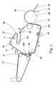
- FIG. 1is a schematic side elevational view of one embodiment of a continuous papermaking process which uses the papermaking belt of the present invention.
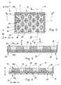
- FIG. 2is a top plan view of a portion of the papermaking belt of the present invention, showing the framework joined to the reinforcing structure and having diamond-shaped paper-side openings of the deflection conduits.
- FIG. 3is a vertical cross-sectional view of a portion of the papermaking belt shown in FIG. 2 as taken along line 3--3.
- FIG. 4is a vertical cross-sectional view of a portion of the papermaking belt shown in FIG. 2 as taken along line 4--4.
- FIG. 5is a simplified representation in vertical cross-section of a portion of the papermaking belt of FIGs. 2-4 showing the overburden.
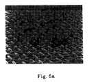
- FIG. 5ais an enlarged photograph of one embodiment of the reinforcing structure of the papermaking belt of the present invention. showing the top of the first layer of the interwoven yarns interconnected in a contacting face-to-face relationship with a second layer (not shown) of interwoven yarns by tie yarns.
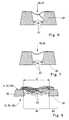
- FIG. 6is a simplified schematic representation of a vertical cross-section showing fibers bridging the conduits of the papermaking belt.
- FIG. 7is a simplified schematic representation of a cross-section similar to FIG. 6.
- FIG. 8is a simplified schematic representation of a cross-section showing full deflection of the fibers into the conduits of the papermaking belt.
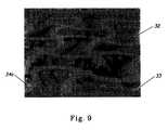
- FIG. 9is an enlarged photograph of one embodiment of the framework joined to the reinforcing structure of the papermaking belt of the present invention, showing the bow-tie openings of the deflection conduits.
- FIG. 9ais a top plan schematic representation of one exemplary framework having bow-tie openings of the deflection conduits, and the portion of the paper web produced using the belt having this exemplary framework.
- FIG. 10is a vertical sectional view of a portion of the paper web shown in FIG. 9a as taken along line 10--10.
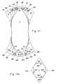
- FIG. 11is an enlarged schematic representation of one exemplary paper-side opening, having a bow-tie shaped configuration, of the deflection conduit of the papermaking belt of the present invention.
- FIG. 11ais an enlarged schematic representation of one exemplary paper-side opening, having a diamond-shaped configuration, of the deflection conduit of the papermaking belt of the present invention.
- FIGs. 11 and 11aare schematic only, illustrating the method of establishing whether a substantial part of the opening of the deflection conduit is not less than about 45 mils in each of its X-Y dimensions.
- FIGs. 11 and 11ashould not be used to scale the areas of the openings 42 which meet the 1.14 mm (45 mil) criterion.
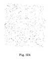
- FIG. 12is a representation of two digitized images of pinholes of the paper web samples, as seen on a computer screen.
- the specificationcontains a detailed description of (1) the papermaking belt of the present invention and (2) the finished paper product of the present invention.
- the papermaking belt of the present inventiontakes the form of an endless belt, papermaking belt 10.
- the papermaking belt 10has a paper-contacting side 11 and a backside 12 opposite the paper-contacting side 11.
- the papermaking belt 10carries a paper web (or "fiber web") in various stages of its formation (an embryonic web 27 and an intermediate web 29). Processes of forming embryonic webs are described in many references, such as U.S. Pat. No. 3,301,746, issued to Sanford and Sisson on Jan. 31, 1974, and U.S. Pat. No. 3,994,771, issued to Morgan and Rich on Nov. 30, 1976.
- the papermaking belt 10travels in the direction indicated by directional arrow B around the return rolls 19a and 19b, impression nip roll 20, return rolls 19c, 19d, 19e, 19f, and emulsion distributing roll 21.
- the loop around which the papermaking belt 10 travelsincludes a means for applying a fluid pressure differential to the embryonic web 27, such as vacuum pickup shoe 24a and multislot vacuum box 24.
- the papermaking belt 10also travels around a predryer such as blow-through dryer 26, and passes between a nip formed by the impression nip roll 20 and a Yankee dryer drum 28.
- the preferred embodiment of the papermaking belt of the present inventionis in the form of an endless belt 10, it can be incorporated into numerous other forms which include, for instance, stationary plates for use in making handsheets or rotating drums for use with other types of continuous process. Regardless of the physical form which the papermaking belt 10 takes, it generally has certain physical characteristics set fourth below.
- the papermaking belt 10 of the present inventionmay be made according to commonly assigned U.S. Pat. No. 5,334,289, issued in the name of Trokhan et al.
- the papermaking belt 10 of the present inventionis generally comprised of two primary elements: a framework 32, and a reinforcing structure 33.
- the framework 32has a first surface 34, a second surface 35 opposite the first surface 34. and deflection conduits 36 extending between the first surface 34 and the second surface 35.
- the first surface 34 of the framework 32contacts the embryonic web fibers to be dewatered, and defines the paper-contacting side 11 of the papermaking belt 10.
- the deflection conduits 36 extending between the first surface 34 and the second surface 35channel water from the embryonic web 27 which rest on the first surface 34 to the second surface 35 and provide areas into which the fibers of the embryonic web 27 can be deflected and rearranged. As used herein.
- the first surface 34 of the framework 32comprises a paper-side network 34a and paper-side openings 42 formed therein. That is to say, the paper-side network 34a comprises a surface of the solid portion of the framework 32. or a portion of the first surface 34, which surrounds and defines the paper-side openings 42 in the first surface 34.
- the second surface 35 of the framework 32comprises a backside network 35a and backside openings 43.
- the backside network 35asurrounds and defines the backside openings 43 in the second surface 35.
- the paper-side openings 42 and the backside openings 43define the deflection conduits 36.
- the paper-side opening 42preferably are uniform shape and are distributed in a non-random, repeating pattern. The pattern comprising a bilaterally staggered array is preferred.
- the backside openings 43are also preferably uniform shape and are distributed in a non-random. repeating pattern. Accordingly, the deflection conduits 36 are preferably arranged in a non-random, repeating pattern comprising bilaterally staggered array. In FIG.
- the openings 42are shown as having a diamond-shaped configuration, but it will be apparent to one skilled in the art that the paper-side network 34a and the backside network 35a can be provided with a variety of patterns having various shapes, sizes, and orientations.
- the practical shapes of the paper-side openings 42 and the backside openings 43include, but are not limited to, circles, ovals, polygons of six and fewer sides, bow-tie shaped figures, weave-like patterns.
- the profile of the cross-section of the walls 44 of the deflection conduits 36can be relatively straight. curved, partially straight and partially curved, or irregular when viewed in cross section. It should be noted that the drawings schematically show the walls 44 of the conduits 36 as straight lines for ease of illustration only. The profile of the cross-section of the walls 44 of the deflection conduits 36 is disclosed in greater detail in U.S. Pat. No. 5,334,289.
- a variety of suitable resinscan be used as the framework 32.
- the framework 32is joined to the reinforcing structure 33.
- the reinforcing structure 33has a paper-facing side 51 and a machine-facing side 52, opposite the paper-facing side 51.
- the framework 32extends outwardly from the paper-facing side 51 of the reinforcing structure 33.
- the reinforcing structure 33strengthens the resin framework 32 and has suitable projected open area to allow the vacuum dewatering machinery employed in the papermaking process to perform adequately its function of removing water from the embryonic web 27, and to permit water removed from the embryonic web 27 to pass through the papermaking belt 10.
- overburdenmeans the portion of the resin framework 32 extending from the paper-facing side 51 of the reinforcing structure 33.
- the overburdenis designated as OB. More particularly, the overburden is defined by the distance between the first surface 34 (and, for this purpose, the paper-side network 34a) of the framework 32 and the paper-facing side 51 of the reinforcing structure 33.
- the increase of thickness and absorbency of the papercan be achieved by increasing a caliper of the embryonic web 27.
- One way of increasing the caliperis to increase the overburden OB.
- the greater the overburden OBthe more fibers can be deflected and accumulated in the deflection conduits 36.
- the greater overburdenenables the conduits 36 to serve adequately their purpose of providing a space into which the fibers of the embryonic web 27 can be deflected so that these fibers can be rearranged without the constraint of the strands of the reinforcing structure 33.
- the preferred range of the overburden used in the prior artis disclosed in U.S. Pat. No. 5,334,289 as being between about 4 mils and about 30 mils (0.102 mm and 0.762 mm).
- the web 29is adhered to a Yankee surface 28 and then removed from the Yankee surface 28 with a doctor blade 30. It has been found that the effective caliper generation occurs at the preferred Yankee speed of not less than about 305 metres/minute (1000 feet per minute) (fpm). More preferably, the Yankee speed is not less than about 1067 metres/minute (3500 fpm).
- the preferred range of the overburdenis between about 1 mil and about 6.5 mils (0.0254 mm and 0.1651 mm), which is considerably less than would be expected from the prior art findings.
- the more preferred range of the overburdenis between about 0.06 mm (2.5) and about 0.14 mm (5.5 mils).
- the most preferable overburden rangeis between about 0.1mm (4) and about 0.13 mm (5 mils).
- the low overburdencan be particularly advantageous if used in combination with large domes and high fiber support.
- the term "large dome”refers to a dome, a substantial portion of which is not less than about 45 mils in each of its dimensions measured in the X-Y plane at the level of paper-side network 34a.
- X, Y and Z directionsare orientations relating to the papermaking belt 10 of the present invention (or paper web disposed on the belt) in a Cartesian coordinate system. In the Cartesian coordinate system described herein, the paper-contacting side 11 and the backside 12 of the papermaking belt 10 lie in the plane formed by the X and Y axes.
- the X axisis the cross-machine direction
- the Y axisis the machine direction
- the Z axisis perpendicular to the plane defined by the X and Y axes.
- the term "substantial portion”means not less than about 40% of the X-Y area of the individual dome and -- accordingly -- not less than about 40% of the area of the individual paper-side opening 42 of the deflection conduit 36, measured in the X-Y plane at the level of the network region 83 and the paper-side network 34a.
- the substantial portion of the paper-side opening 42 of the conduit 36should also be not less than about 45 mils in each of its dimensions measured in the X-Y plane at the level of the paper-side network 34a.
- the symbol "A"indicates one of the dimensions of the opening 42 as measured in the X-Y plane at the level of the paper-side network 34a.
- FIGs. 11 and 11aillustrate what is meant by a requirement that a substantial portion of the paper-side opening 42 is not less than about 45 mils in each of its dimensions measured in the X-Y plane at the level of paper-side network 34a.
- FIG. 11an exemplary paper-side opening 42 in the form of a bow-tie shaped figure is shown.
- the symbols "Sl" through “S18”represent individual areas of the paper-side opening 42.
- the individual areas S1 through S18are formed by corresponding border lines B1 through B18 and the perimeter of the opening 42.
- the length of each border line B1, B2, .... B18is equal to 45 mils.
- FIG. 11shows, at least some of the dimensions of the individual areas S through S18 are less than 45 mils.
- the number of the border lines and the location of each border lineare found such as to maximize the resulting areas formed by the multiplicity of the border lines and the perimeter of the opening 42.
- the symbol "S"represents the portion of the opening 42 formed by subtracting from the whole area of the opening 42 the resulting areas formed by the border lines and the perimeter of the paper-side opening 42.
- the perimeter of the area Sis designated by a dotted line. According to the present invention, S should comprise a substantial portion of the opening 42.
- FIG. 11aan exemplary paper-side opening 42 in the form of a diamond-shaped figure is shown.
- the symbols "S21,” “S22,” “S23,” “S24”represent individual areas, or portions of the paper-side opening 42, formed by the border lines B21, B22, B23, B24, each of them being equal to 45 mils, and the perimeter of the opening 42.
- the symbol "S * "represents the portion of the opening 42 formed by subtracting the resulting areas of the opening 42 formed by the border lines B21-B24 and the line defining the perimeter of the paper-side opening 42 from the whole area of the opening 42. According to the present invention. S * should comprise a substantial portion of the opening 42.
- FIG. 11illustrates the situation when the sum of the resulting areas formed by the border lines B1 through B 18 and the perimeter are smaller than the sum of the individual areas S through S18.
- FIG. 11aillustrates the situation when the resulting areas formed by the border lines B21 through B24 and the perimeter of the opening 42 are equal to the sum of the individual areas S21 - S24.
- FIGs. 11 and 11aare presented for the purposes of illustration only, and not for the purposes of limitation.
- the paper-side openings 42can comprise a variety of shapes including, but not limited to, ovals, polygons, weave-like patterns and the like, and the same method of establishing whether the substantial part of the opening 42 is not less than 45 mils in any of its dimensions measured in X-Y plane would apply.
- FIGs. 11 and 11aare schematic only, illustrating the method of establishing whether the substantial part of the opening 42 is not less than about 45 mils in each of its dimensions measured in the X-Y plane.
- FIGs. 11 and 11ashould not be used to scale the real dimensions of the openings 42, the lengths and locations of the border lines, and the areas formed by the border lines and the perimeter(s) of the openings 42.
- the domesare formed when the deflection of the fibers into the deflection conduits 36 occurs.
- water removalresults in a decrease in fiber mobility in the embryonic web 27.
- This decrease in fiber mobilitytends to fix the fibers in place after they have been deflected and rearranged.
- Deflection of the fibers into the deflection conduits 36can be induced by, for example, the application of differential fluid pressure to the embryonic web 27.
- One preferred method of applying differential pressureis by exposing the embryonic web 27 to a vacuum through deflection conduits 36. In FIG. 1 the preferred method is illustrated by the use of vacuum box 24.
- positive pressure in the form of air pressurecan be used.
- the rearrangement of the fibers in the embryonic web 27can generally take one of two models dependent on a number of factors including fiber length.
- the free ends of longer fiberscan be merely bent into the conduits 36 while their opposite ends are restrained in the region of network surfaces. As schematically shown in FIG. 6, these free ends of the longer fibers can bond together in the area of the deflection conduit 36 without reaching the reinforcing structure 33. Or, as schematically shown in FIG. 7, the middle parts of longer fibers can be bent into the conduit 36 without being fully deflected. Thus, "bridging" of the deflection conduit 36 occurs. Alternatively, fibers (predominantly, the shorter ones) can actually be fully deflected into the conduit 36 and contact the reinforcing structure 33, as shown in FIG. 8.
- the substantial portion of the paper-side opening 42 of the deflection conduit 36is not less than about 1.14 mm (45 mils) in each of its dimensions measured in the X-Y plane. This size allows substantially all fibers that have been deflected to be fully deflected into the deflection conduits 36, as schematically shown in FIG. 8. While applicants decline to be bound by any particular theory, it appears that, providing the low overburden and high fiber support are present, full deflection of the fibers into the conduits 36 provides more caliper, improves thickness impression and enhances strength of the finished paper product, compared to paper having domes formed by other methods than full deflection of the fibers into the conduits 36.
- the reinforcing structure 33is one of the primary elements of the papermaking belt of the present invention.
- the reinforcing structure 33strengthens the resin framework 32 and has a suitable projected open area in order to allow the vacuum dewatering machinery employed in the papermaking process to adequately perform its function of removing water from partially-formed webs of paper, and to permit water removed from the paper web to pass through the papermaking belt 10. Therefore, the reinforcing structure 33 should be highly permeable to fluids such as air and water.
- “highly permeable”it is meant that the reinforcing structure 33 should have an air permeability not less than about 4.1 standard cubic metres per second per square metre 800 cubic feet per minute (cfm) per square foot of its surface at a pressure differential of 100 Pascals.
- the reinforcing structure 33 of the present inventionhas the preferred air permeability between about 3.7 (900) and about 4.5 cubic meters per second per square meter (1100 cfm per square foot) of its surface at a pressure differential of 100 Pascals. More preferably, the air permeability of the reinforcing structure 33 of the present invention is between about 3.9 (950) and about 4.3 cubic meters per second per square meter (1050 cfm per square foot) at a pressure differential of 100 Pascals. The most preferable air permeability of the reinforcing structure 33 of the present invention is about 4.1 cubic meters per second per square meter 1000 cfm per square foot at a pressure differential of 100 Pascals.
- the reinforcing structure 33 of the present inventionhas also an important function of supporting the fibers fully deflected into the conduits 36, not allowing them to be blown through the belt 10. Therefore, the high fiber support provided by the reinforcing structure 33 of the present invention is of primary importance.
- high fiber supportit is meant that the reinforcing structure 33 of the present invention has a Fiber Support Index of not less than about 75.
- the Fiber Support Index or FSIis defined in Robert L. Beran, "The Evaluation and Selection of Forming Fabrics," Tappi /April 1979, Vol. 62, No. 4 .
- the reinforcing structure of the present inventionhas FSI not less than 85. More preferably, the FSI is greater than 90.
- the reinforcing structure 33can take any number of different forms. It can comprise a woven element, a non-woven element, a screen, a net, a scrim, or a band or plate having plurality of holes.
- the reinforcing structure 33comprises a woven element, and more particularly, a foraminous woven element, such as disclosed in U.S. Pat. No. 5,334,289. More preferably, the reinforcing structure comprises a first layer of interwoven yarns and a second layer of interwoven yarns being substantially parallel to each other and interconnected in a contacting face-to-face relationship by a tie yarns.
- the first layer and the second layercan individually comprise a plurality of machine-direction yarns interwoven with a plurality of cross-machine direction yarns.
- This type of the reinforcing structure 33is illustrated in FIG. 5a.
- U.S. Patent application Serial No: 08/254,387, filed June 2, 1994 in the names of Stelljes, Jr. et al. and allowed on September 12, 1995 under Issue Batch No. P13shows a suitable reinforcing structure 33. According to U.S.
- the web facing first layeris woven so that the top dead center longitude of each yarn of the first layer that is in the top plane of the paper-facing side 51 does not extend more than 1.5 yarn diameters, and preferably not more than 1.0 yarn diameters away from the top plane of the paper-facing side 51, and remains within 1.0 or 1.5 yarn diameters of the paper-facing side 51 at all positions, unless such yarn is a tie yarn interconnecting the first and the second layers.
- a papermaking belt 10 according to the present inventioncan be made using a felt as a reinforcing structure, as set forth in the patent applications: Serial No. 08/391,372, filed 2/15/95 in the name of Trokhan et al. and entitled: "Method Of Applying A Curable Resin To A Substrate For Use In Papermaking;” Serial No. 08/268,213, filed 6/29/94 in the name of Trokhan et al. and allowed on 8/22/95, entitled: "Paper Structures Having At Least Three Regions Disposed At Different Elevations, and Apparatus And Process For Making The Same;” Serial No.
- Papermaking fibers useful in the present inventioninclude those cellulosic fibers commonly known as wood pulp fibers. Fibers derived from soft woods (gymnosperms or coniferous trees) and hard woods (angiosperms or deciduous trees) are contemplated for use in this invention. Preferably, the weight ratio: soft wood fibers/hard wood fibers is about 25/75. The particular species of trees from which the fibers are derived are immaterial. In addition to the various wood pulp fibers, other cellulosic fibers, such as cotton linters, rayon, and bagasse, can be used in this invention. Synthetic fibers, such as polyester and polyolefin fibers can also be used.
- the improved finished paper web 80 of the present inventionis characterized as having two distinct regions: a network region 83 and a dome region 84.
- the network region 83corresponds to and is formed on the paper-side network 34a of the first surface 34 of the papermaking belt 10.
- the network region 83is an essentially continuous, macroscopically monoplanar region having a non-random, repeating pattern. It is described as "continuous” because it comprises the system of essentially uninterrupted lines forming at least one essentially unbroken net-like pattern of essentially uniform physical characteristics. The pattern is said to be “essentially” continuous because it is recognized that the interruptions in the pattern may be tolerable, but not preferred.
- the network region 83is described as "macroscopically monoplanar" because the top surface of the network region (i.e., the surface lying on the same side of the paper web as the protrusions of the domes) is essentially planar when the paper web 80 as a whole is placed in a planar configuration. It is “essentially” monoplanar because minor deviations from absolute planarity are tolerable. but not preferred.
- the dome region 84comprises a plurality of domes dispersed throughout the whole of the network region 83 Essentially each individual dome is encompassed by, and isolated one from another, by the network region 83.
- the domesare distributed in a non-random repeating pattern. Preferably this repeating pattern comprises a bilaterally staggered array. A substantial portion of each dome is greater than about 45 mils in each of its dimension measured in the X-Y plane at the level of the network region 83.
- the shape of the domesis defined by the network region 83. That is to say, the shape of the domes in the X-Y plane is defined by the configuration of the paper-side openings 42 of the deflection conduits 36.
- domes in the X-Y planeinclude, but are not limited to, circles, ovals, polygons of six and fewer sides, bow-tie shaped figures, weave-like patterns.
- domesare in the form of a closed figured, such as a bow-tie shaped figure, diamond-shaped figure and the like.
- FIG. 9aschematically shows the exemplary X-Y geometry of a part of the paper web 80 (and, naturally, of the openings 42 of the deflection conduits 36) having the domes in the form of a bow-tie shaped figure.
- FIG. 9aOnly a portion of the paper web (and the first surface 34a) showing a repeating pattern is shown in FIG. 9a.
- the symbol "MD”indicates machine direction, i.e., the direction which is parallel to the flow of the web through the equipment.
- the symbol “CD”indicates cross machine direction, i.e., the direction perpendicular to the machine direction in the X-Y plane.
- bow-tie domeis one exemplary design.
- Other designs of bow-tie figurescan be utilized in the present invention, as well as other, different from the bow-tie shapes of the dome.
- the practical shapes of the domesinclude, but not limited to, circles, ovals, polygons of six and fewer sides, bow-tie shaped figures, weave-like patterns and the like.
- the network region 83 of the paper 80 of the present inventionhas a high density (weight per unit volume) relative to the density of the dome region 84.
- the difference in the densitiesprimarily occurs as a result of deflection of fibers into the deflection conduits 36.
- the embryonic web 27At the time the embryonic web 27 is associated with the framework 32, the embryonic web 27 has an essentially uniform basis weight.
- fibersare free to rearrange and migrate from adjacent the surface of the paper-side network 34a into the deflection conduits 36 thereby creating a relative paucity of fibers over the surface of the paper-side network 34a and a relative superfluity of fibers fully deflected into the deflection conduits 36.
- Some deflected fibersare "pulled apart” and separated from each other by the application of the vacuum pressure destroying bonds existing between these fibers.
- the application of the vacuum pressuretends to compress the network region 83 (i.e., that portion of the embryonic web 27 which corresponds with the paper-side network 34a) over the surface of the paper-side network 34a, while the dome region 84 (i.e., the portion of the embryonic web 27 within the deflection conduits 36) is not compressed over the surface of the paper-side network 34a.
- This compression of the network region 83tends to further exaggerate the difference in densities between the two regions.
- pressing the network area 83 against the Yankee dryer drum 28even further increases the density of the network 83.
- the combination of large domes, low overburden and high fiber support of the belt's reinforcing structurereduces the number of pinholes in the paper of the present invention.
- the number of pinholes in the dome areameasured by the analytical procedure described below is not greater than 0.12 pinholes per mm 2 (7500 pinholes per 100 square inches) of the paper web.
- the number of pinholesis not greater than 0.08 pinholes per mm 2 (5000 pinholes per 100 square inches) of the paper web.
- the caliper of the paper webis measured under a pressure of 0.15 g/mm 2 (95 grams per square inch) using a round presser foot having a diameter of 50.8 mm (2 inches). The dwell time is 3 seconds.
- the calipercan be measured using a Thwing-Albert Thickness Tester Model 89-100, manufactured by the Thwing-Albert Instrument Company of Philadelphia, Pennsylvania.
- the caliperis measured under TAPPI temperature and humidity conditions.
- the caliper of the finished paper webis preferably between 0.23 mm and 0.76 mm (9 mils and 30 mils). More preferably, the caliper is between 0.28 mm and 0.76 mm (11 mils and 30 mils).
- the most preferable caliper of the finished paper webis between 0.3 mm and 0.36 mm (12 mils and 14 mils).
- a Macintosh computer with a math-coprocessor, at least 4 MB of RAM, and a monitor capable of 256 shades of graymay be used in conjunction with the optical scanner HP ScanJet IIp full page scanner with DeskScan software Version 1.5.2. or later.
- Macintosh Quadra 800 with MB of 8 RAM, and Iomega External Removable Cartridge Driveare preferred.
- An Apple High Resolution color monitor, Model M1212(or a model allowing a higher resolution) can be used.
- Suitable softwareis Microsoft Excel, Version 4.0 or later, and Image Version 1.45, available from the National Institute of Health, in Washington, D.C., and QuicKeys 2v 2.1.
- a parent roll of the finished paper web 80is divided along its longitudinal axis into five approximately equal parts. Usually, two parent rolls produced by the same equipment and at the same time are used for testing. At least one paper web sample, randomly taken from each of the five parts of each parent roll is tested. Thus, ten paper web samples are usually tested.
- a web sampleis placed on the glass of an optical scanner under a black background board.
- the image through the scanneris digitized and viewed in two dimensions on a computer monitor.
- the settingsare as follows: Brightness is 106; Contrast is 178; Scaling is 200.
- Print Pathis set at 3.9 dots per mm (100 dots per inch).
- the scanning sizeis about 64500 mm 2 (10 square inches).
- the sampleis scanned into the computer as an image file composed of pixels.
- the term "pixel"indicates the smallest discrete digitized picture element generated by a computer.
- the pixelof about 0.065 mm 2 (0.0001 square inches) is used.
- FIG. 12illustrates the digitized image of the paper web sample having pinholes, as it could be seen on the computer screen.
- the image fileis processed by an image analysis application that identifies and measures each pinhole in the image according to the specific criteria. For the samples described therein, the threshold of gray level of 254 has been found to work well in the detection of pinholes.
- the macroselectively measures all of the "suspected" pinholes that have gray value of 254. Then, the data file which lists the size of each pinhole it has found is created. Microsoft Excel is then used to tabulate the data regarding the size, number and distribution of all found pinholes.
- Appendix 2represents the resulting Pinhole Analysis. As can be seen from the Appendix 2, the pinhole analysis allows to evaluate not only the number of pinholes, but also -- the numerical distribution of the pinholes according to their size, an average single pinhole size, and other relevant data.
- FIG. 12shows the digitized images of the paper web samples produced using two different belts.
- the Image Ais the image of the sample produced using the papermaking belt having a high overburden (OB is about 0.19 mm (7.5 mils)).
- the Image Bis the image of the sample produced using the papermaking belt having a low overburden according to the present invention (OB is about 0.12 mm (4.9 mils)).
- Other characteristics of the two beltssuch as dome size and Fiber Support Index, are about equal.
- Visual comparison of the two samples shown in FIG. 12illustrates that the paper web produced using the belt with a low overburden according to the present invention has significantly less number of pinholes (Image B) compared to the paper web produced using the papermaking belt having a higher overburden (Image A).
- the Diagram Arepresents the data relating to the samples produced using the belt having a high overburden of about 0.19 mm (7.5 mils).
- the Diagram Brepresents the data relating to the samples produced using the belt having a low overburden of about 0.12 mm (4.9 mils).
- the number of pinholes in the samples produced using the belt having a high overburdenis 0.18 pinholes per mm 2 (11325 pinholes per 100 square inches) (Diagram A).
- the number of pinholes in the samples produced using the belt having the low overburden according to the present inventionis 0.025 pinholes per mm 2 (1592 pinholes per 100 square inches) (Diagram B).
- the low overburden belt of the present inventionimproves pinholing not only in terms of the amount of the pinholes, but also -- in terms of the size of the pinholes.
- the average number of pinholes having an area of about one pixelis 5852, and the average number of pinholes having an area of about 20 pixels and larger is 51.
- the corresponding numbersare 1084 and 1, as presented in the Diagram B.
- Type of Reinforcing Structure Fiber Support Index Overburden mm(mil) Belt Air perm, cubic meters per second (cfm) Network Area (%) Uncalendered Caliper mm, (mil) Number of Pinholes per 100 square inches Pinhole Area (Square Mils per 100 square inches) PVT-533 94 0.19 (7.5) 2 (487) 40 0.6 (23.5) 9,646 654,484 PVT-533 94 0.07 (2.9) 2 (477) 40 0.48 (19.0) 2,671 121,631 PVT-543 94 0.08 (3.1) 1.9 (453) 35 0.45 (17.9) 2,045 86,377 PVT-543 94 0.12 (4.9) 2 (494) 35 0.52 (20.5) 2,284 100,101
- the belts having the same Fiber Support Index and relatively similar air permeabilitywere tested in plant manufacturing conditions.
- the pinhole counts related to the belts having a low overburden of 0.07 mm (2.9 mils), 0.08 mm (3.1 mils), and 0.12 mm (4.9 mils)are significantly less than the pinhole count related to the belt having a high overburden of 0.19 mm (7.5 mils) (first line of the Table I).
- Table IIrepresents the results of testing several belts at the pilot plant under simulated conditions. As could be seen from the Table II, the best results in pinholing count (1,101 and 139 ) were achieved using the belts having low overburden of 0.1 mm (3.9 mils) and 0.1mm (4.0 mils) (third and sixth lines of the Table II). As between these two belts having low overburdens, the best results in pinholing were received using the belt with the higher Fiber Support Index of 94 (sixth line of the Table II).
Landscapes
- Engineering & Computer Science (AREA)
- Mechanical Engineering (AREA)
- Health & Medical Sciences (AREA)
- Toxicology (AREA)
- Physics & Mathematics (AREA)
- Oral & Maxillofacial Surgery (AREA)
- Thermal Sciences (AREA)
- Paper (AREA)
- Laminated Bodies (AREA)
Abstract
Description
(One mil being equal to one-thousandths of an inch, or 0.0254 mm)
| Type of Reinforcing Structure | Fiber Support Index | Overburden mm, (mil) | Belt Air perm, cubic meters per second (cfm) | Network Area (%) | Uncalendered Caliper mm, (mil) | Number of Pinholes per 100 square inches | Pinhole Area (Square Mils per 100 square inches) |
| PVT-533 | 94 | 0.19 (7.5) | 2 (487) | 40 | 0.6 (23.5) | 9,646 | 654,484 |
| PVT-533 | 94 | 0.07 (2.9) | 2 (477) | 40 | 0.48 (19.0) | 2,671 | 121,631 |
| PVT-543 | 94 | 0.08 (3.1) | 1.9 (453) | 35 | 0.45 (17.9) | 2,045 | 86,377 |
| PVT-543 | 94 | 0.12 (4.9) | 2 (494) | 35 | 0.52 (20.5) | 2,284 | 100,101 |
| Type of Reinforcing Structure | Fiber Support Index | Overburden (mil) | Belt Air perm, cubic meters per second (cfm) | Network Area (%) | Uncalendered Caliper (mil) | Number of Pinholes per 100 square inches | Pinhole Area (Square Mils per 100 square inches) |
| HMT-502 | 69 | 0.29 (11.4) | 2 (488) | 40 | 0.53 (20.8) | 10,134 | 584,128 |
| HMT-502 | 69 | 0.20 (7.8) | 2 (479) | 40 | 0.47 (18.4) | 5,395 | 260,584 |
| HMT-502 | 69 | 0.1 (3.9) | 2.2 (532) | 40 | 0.4 (15.6) | 1,101 | 42,908 |
| PVT-543 | 94 | 0.29 (11.3) | 2 (485) | 40 | 0.47 (18.7) | 1,767 | 69,693 |
| PVT-543 | 94 | 0.23 (9.1) | 1.7 (415) | 40 | 0.45 (17.9) | 3,514 | 142,039 |
| PVT-543 | 94 | 0.1 (4.0) | 1.9 (463) | 40 | 0.34 (13.5) | 139 | 4,490 |
Claims (10)
- A papermaking belt (10) having a paper-contacting side (11) and a backside (12)opposite said paper-contacting side (11), said papermaking belt (10) comprising:characterised in that said reinforcing structure (33) has a Fiber Support Index notless than 75;a reinforcing structure (33) having a paper-facing side (51) and a machine-facingside (52) opposite said paper-facing side (51), said reinforcing structure (33)having an air permeability of not less than 4.1 standard cubic metres per secondper square metre (800 cfm); anda framework (32) joined to said reinforcing structure (33) and extending outwardlyfrom said paper-facing side (51) of said reinforcing structure (33) to form anessentially continuous network, said framework (32) having a first surface (34)defining said paper-contacting side (11) of said papermaking belt (10), a secondsurface (35) opposite said first surface (34), and deflection conduits (36) extendingbetween said first surface (34) and said second surface (35), said first surface (34)comprising a paper-side network (34a) and paper-side openings (42) and saidsecond surface (35) comprising a backside network (35a) and backside openings(43), said paper-side openings (42) and said backside openings (43) defining saiddeflection conduits (36),
and in that said framework (32) extends outwardly not more than 0.165 mm (6.5mils) from said paper-facing side (51) of said reinforcing structure (33);
and in that a substantial portion of each of said paper-side openings (42) is notless than 1.14 mm (45 mils) in each of its dimensions measured in the X-Y plane atthe level of said paper-side network (34a). - The papermaking belt (10) of Claim 1, characterized in that said reinforcingstructure (33) comprises a plurality of machine-direction yarns interwoven with aplurality of cross-machine direction yarns, and preferably a first layer of interwovenyams and a second layer of interwoven yarns, said first and second layers beingsubstantially parallel to each other and interconnected in a contacting face-to-facerelationship by tie yams.
- The papermaking belt (10) of Claim 1, characterized in that said reinforcingstructure (33) comprises a felt.
- The papermaking belt (10) of any of Claims 1, 2 or 3 characterized in that saidpaper-side openings (42) are disposed on said first surface (34) in a non-random,repeating pattern, and preferably said non-random, repeating pattern comprises abilaterally staggered array.
- The papermaking belt (10) of Claim 4, characterized in that each of said paper-sideopenings (42) defines a closed figure.
- The papermaking belt (10) of either of Claims 4 or 5, characterized in that theamount of said deflection conduits (36) is not greater than 0.124 conduits persquare millimeter (80 conduits per square inch).
- The papermaking belt (10) of Claim 1, wherein said reinforcing structure (33)comprises a first layer of a plurality of interwoven yams having a top dead centerlongitude remaining within 1.5 yam diameters of said paper-facing side (51), and asecond layer of a plurality of interwoven yams, said first and second layers beingsubstantially parallel to each other and interconnected in a contacting face-to-facerelationship by tie yams.
- A paper web (80) having two regions and comprising:an essentially continuous, essentially macroscopically monoplanar network region(83), and a dome region (84) comprising discrete domes, said domes beingdispersed throughout, encompassed by, and isolated one from another by saidnetwork region (83), the density of said network region (83) being greater than thedensity of said dome region (84), characterised in that a substantial portion of eachof said domes is not less than 1.14 mm (45 mils) in each of its dimensionsmeasured in the X-Y plane at the level of said network region (83).
- A paper web (80) of Claim 8, characterized in that said domes are distributed in arepeating pattem, preferably said repeating pattern comprising a bilaterallystaggered array, and more preferably the perimeter of substantially each of saiddomes defining a closed figure.
- A paper web (80) of Claim 9, characterized in that the amount of said domes is notgreater than 0.124 domes per square millimeter (80 domes per square inch) of saidpaper web (80) and preferably said closed figure comprises a bow-tie shapedfigure.
Applications Claiming Priority (3)
| Application Number | Priority Date | Filing Date | Title |
|---|---|---|---|
| US588643 | 1996-01-19 | ||
| US08/588,643US5679222A (en) | 1990-06-29 | 1996-01-19 | Paper having improved pinhole characteristics and papermaking belt for making the same |
| PCT/US1997/000634WO1997026407A1 (en) | 1996-01-19 | 1997-01-16 | Paper having improved pinhole characteristics and papermaking belt for making the same |
Publications (2)
| Publication Number | Publication Date |
|---|---|
| EP0874938A1 EP0874938A1 (en) | 1998-11-04 |
| EP0874938B1true EP0874938B1 (en) | 2001-06-13 |
Family
ID=24354700
Family Applications (1)
| Application Number | Title | Priority Date | Filing Date |
|---|---|---|---|
| EP97902950AExpired - LifetimeEP0874938B1 (en) | 1996-01-19 | 1997-01-16 | Paper having improved pinhole characteristics and papermaking belt for making the same |
Country Status (15)
| Country | Link |
|---|---|
| US (1) | US5679222A (en) |
| EP (1) | EP0874938B1 (en) |
| JP (2) | JP3160295B2 (en) |
| KR (1) | KR100288844B1 (en) |
| CN (2) | CN1082588C (en) |
| AT (1) | ATE202169T1 (en) |
| AU (1) | AU728265B2 (en) |
| BR (1) | BR9707141A (en) |
| CA (1) | CA2243322C (en) |
| DE (1) | DE69705200T2 (en) |
| ES (1) | ES2159837T3 (en) |
| MY (1) | MY133810A (en) |
| TW (1) | TW324757B (en) |
| WO (1) | WO1997026407A1 (en) |
| ZA (1) | ZA97368B (en) |
Families Citing this family (151)
| Publication number | Priority date | Publication date | Assignee | Title |
|---|---|---|---|---|
| US6103067A (en)* | 1998-04-07 | 2000-08-15 | The Procter & Gamble Company | Papermaking belt providing improved drying efficiency for cellulosic fibrous structures |
| US6110324A (en)* | 1998-06-25 | 2000-08-29 | The Procter & Gamble Company | Papermaking belt having reinforcing piles |
| US6099781A (en) | 1998-08-14 | 2000-08-08 | The Procter & Gamble Company | Papermaking belt and process and apparatus for making same |
| US6149849A (en) | 1998-08-14 | 2000-11-21 | The Procter & Gamble Copmany | Process and apparatus for making papermaking belt |
| US6251331B1 (en) | 1998-09-09 | 2001-06-26 | The Procter & Gamble Company | Process and apparatus for making papermaking belt using fluid pressure differential |
| DE69913741T2 (en)* | 1998-09-30 | 2004-12-09 | The Procter & Gamble Company, Cincinnati | THICK PAPER AND PAPER MAKING FABRIC FOR ITS PRODUCTION |
| US20040045685A1 (en)* | 1998-11-24 | 2004-03-11 | The Procter & Gamble Company | Process for the manufacture of multi-ply tissue |
| EP1004703A1 (en)* | 1998-11-24 | 2000-05-31 | The Procter & Gamble Company | Multi-ply tissue, and process for its manufacture |
| US6265052B1 (en) | 1999-02-09 | 2001-07-24 | The Procter & Gamble Company | Tissue paper |
| US6344241B1 (en) | 1999-06-07 | 2002-02-05 | The Procter & Gamble Company | Process and apparatus for making papermaking belt using extrusion |
| US6358594B1 (en) | 1999-06-07 | 2002-03-19 | The Procter & Gamble Company | Papermaking belt |
| US6501002B1 (en) | 1999-06-29 | 2002-12-31 | The Proctor & Gamble Company | Disposable surface wipe article having a waste contamination sensor |
| US6447642B1 (en)* | 1999-09-07 | 2002-09-10 | The Procter & Gamble Company | Papermaking apparatus and process for removing water from a cellulosic web |
| US6602387B1 (en) | 1999-11-26 | 2003-08-05 | The Procter & Gamble Company | Thick and smooth multi-ply tissue |
| US6602577B1 (en) | 2000-10-03 | 2003-08-05 | The Procter & Gamble Company | Embossed cellulosic fibrous structure |
| US6420100B1 (en) | 2000-10-24 | 2002-07-16 | The Procter & Gamble Company | Process for making deflection member using three-dimensional mask |
| US6743571B1 (en) | 2000-10-24 | 2004-06-01 | The Procter & Gamble Company | Mask for differential curing and process for making same |
| US6660129B1 (en)* | 2000-10-24 | 2003-12-09 | The Procter & Gamble Company | Fibrous structure having increased surface area |
| US6576090B1 (en) | 2000-10-24 | 2003-06-10 | The Procter & Gamble Company | Deflection member having suspended portions and process for making same |
| US6576091B1 (en) | 2000-10-24 | 2003-06-10 | The Procter & Gamble Company | Multi-layer deflection member and process for making same |
| US6989075B1 (en) | 2000-11-03 | 2006-01-24 | The Procter & Gamble Company | Tension activatable substrate |
| US6610173B1 (en) | 2000-11-03 | 2003-08-26 | Kimberly-Clark Worldwide, Inc. | Three-dimensional tissue and methods for making the same |
| US6602410B1 (en) | 2000-11-14 | 2003-08-05 | The Procter & Gamble Comapny | Water purifying kits |
| US6701637B2 (en) | 2001-04-20 | 2004-03-09 | Kimberly-Clark Worldwide, Inc. | Systems for tissue dried with metal bands |
| US20030042195A1 (en)* | 2001-09-04 | 2003-03-06 | Lois Jean Forde-Kohler | Multi-ply filter |
| US7805818B2 (en) | 2001-09-05 | 2010-10-05 | The Procter & Gamble Company | Nonwoven loop member for a mechanical fastener |
| US6790314B2 (en) | 2001-11-02 | 2004-09-14 | Kimberly-Clark Worldwide, Inc. | Fabric for use in the manufacture of tissue products having visually discernable background texture regions bordered by curvilinear decorative elements and method thereof |
| US6821385B2 (en) | 2001-11-02 | 2004-11-23 | Kimberly-Clark Worldwide, Inc. | Method of manufacture of tissue products having visually discernable background texture regions bordered by curvilinear decorative elements using fabrics comprising nonwoven elements |
| US6787000B2 (en) | 2001-11-02 | 2004-09-07 | Kimberly-Clark Worldwide, Inc. | Fabric comprising nonwoven elements for use in the manufacture of tissue products having visually discernable background texture regions bordered by curvilinear decorative elements and method thereof |
| DE60225580T2 (en) | 2001-11-02 | 2009-04-23 | Kimberly-Clark Worldwide, Inc., Neenah | Nonwoven fabric covering for use in the manufacture of tissue products having optically identifiable background structural areas bounded by curvilinear decorative elements and methods of making tissue products |
| US6749719B2 (en) | 2001-11-02 | 2004-06-15 | Kimberly-Clark Worldwide, Inc. | Method of manufacture tissue products having visually discernable background texture regions bordered by curvilinear decorative elements |
| US6746570B2 (en) | 2001-11-02 | 2004-06-08 | Kimberly-Clark Worldwide, Inc. | Absorbent tissue products having visually discernable background texture |
| US20030157000A1 (en)* | 2002-02-15 | 2003-08-21 | Kimberly-Clark Worldwide, Inc. | Fluidized bed activated by excimer plasma and materials produced therefrom |
| US20030199404A1 (en)* | 2002-04-23 | 2003-10-23 | The Procter & Gamble Company | Hotmelt compositions and related articles |
| US7128810B2 (en) | 2002-10-10 | 2006-10-31 | Albany International Corp. | Anti-rewet press fabric |
| US7128809B2 (en)* | 2002-11-05 | 2006-10-31 | The Procter & Gamble Company | High caliper web and web-making belt for producing the same |
| US7169265B1 (en) | 2002-12-31 | 2007-01-30 | Albany International Corp. | Method for manufacturing resin-impregnated endless belt and a belt for papermaking machines and similar industrial applications |
| US7005043B2 (en)* | 2002-12-31 | 2006-02-28 | Albany International Corp. | Method of fabrication of a dryer fabric and a dryer fabric with backside venting for improved sheet stability |
| US7022208B2 (en)* | 2002-12-31 | 2006-04-04 | Albany International Corp. | Methods for bonding structural elements of paper machine and industrial fabrics to one another and fabrics produced thereby |
| US7919173B2 (en)* | 2002-12-31 | 2011-04-05 | Albany International Corp. | Method for controlling a functional property of an industrial fabric and industrial fabric |
| US7005044B2 (en)* | 2002-12-31 | 2006-02-28 | Albany International Corp. | Method of fabricating a belt and a belt used to make bulk tissue and towel, and nonwoven articles and fabrics |
| US7008513B2 (en)* | 2002-12-31 | 2006-03-07 | Albany International Corp. | Method of making a papermaking roll cover and roll cover produced thereby |
| US7166196B1 (en) | 2002-12-31 | 2007-01-23 | Albany International Corp. | Method for manufacturing resin-impregnated endless belt structures for papermaking machines and similar industrial applications and belt |
| US7014735B2 (en) | 2002-12-31 | 2006-03-21 | Albany International Corp. | Method of fabricating a belt and a belt used to make bulk tissue and towel, and nonwoven articles and fabrics |
| US20050045293A1 (en) | 2003-09-02 | 2005-03-03 | Hermans Michael Alan | Paper sheet having high absorbent capacity and delayed wet-out |
| US6991706B2 (en)* | 2003-09-02 | 2006-01-31 | Kimberly-Clark Worldwide, Inc. | Clothlike pattern densified web |
| US20050202068A1 (en) | 2004-03-12 | 2005-09-15 | Hasenoehrl Erik J. | Disposable nonwoven mitt |
| SE529130C2 (en)* | 2004-05-26 | 2007-05-08 | Metso Paper Karlstad Ab | Paper machine for manufacturing fiber web of paper, comprises clothing that exhibits three-dimensional structure for structuring fiber web |
| USD512840S1 (en) | 2004-05-28 | 2005-12-20 | The Procter & Gamble Company | Surface pattern of a paper product |
| US7297231B2 (en) | 2004-07-15 | 2007-11-20 | Kimberly-Clark Worldwide, Inc. | Binders curable at room temperature with low blocking |
| US20060088697A1 (en)* | 2004-10-22 | 2006-04-27 | Manifold John A | Fibrous structures comprising a design and processes for making same |
| US20060088696A1 (en)* | 2004-10-25 | 2006-04-27 | The Procter & Gamble Company | Reinforced fibrous structures |
| US8911850B2 (en)* | 2005-06-08 | 2014-12-16 | The Procter & Gamble Company | Amorphous patterns comprising elongate protrusions for use with web materials |
| US7374639B2 (en)* | 2005-06-08 | 2008-05-20 | The Procter & Gamble Company | Papermaking belt |
| US7694433B2 (en) | 2005-06-08 | 2010-04-13 | The Procter & Gamble Company | Web handling apparatus and process for providing steam to a web material |
| US7597777B2 (en)* | 2005-09-09 | 2009-10-06 | The Procter & Gamble Company | Process for high engagement embossing on substrate having non-uniform stretch characteristics |
| US20070098984A1 (en)* | 2005-11-01 | 2007-05-03 | Peterson James F Ii | Fiber with release-material sheath for papermaking belts |
| US20070137814A1 (en)* | 2005-12-15 | 2007-06-21 | Kimberly-Clark Worldwide, Inc. | Tissue sheet molded with elevated elements and methods of making the same |
| US7524403B2 (en)* | 2006-04-28 | 2009-04-28 | Voith Paper Patent Gmbh | Forming fabric and/or tissue molding belt and/or molding belt for use on an ATMOS system |
| US8152959B2 (en)* | 2006-05-25 | 2012-04-10 | The Procter & Gamble Company | Embossed multi-ply fibrous structure product |
| US7914649B2 (en)* | 2006-10-31 | 2011-03-29 | The Procter & Gamble Company | Papermaking belt for making multi-elevation paper structures |
| US7799411B2 (en)* | 2006-10-31 | 2010-09-21 | The Procter & Gamble Company | Absorbent paper product having non-embossed surface features |
| USD618920S1 (en) | 2007-05-02 | 2010-07-06 | The Procter & Gamble Company | Paper product |
| EP2147382B1 (en)* | 2007-05-15 | 2012-10-31 | Chronologic Pty Ltd | Method and system for reducing triggering latency in universal serial bus data acquisition |
| DE502007007082D1 (en)* | 2007-12-04 | 2011-06-09 | Heimbach Gmbh & Co Kg | Forming screen for use in a paper machine |
| US7914648B2 (en)* | 2007-12-18 | 2011-03-29 | The Procter & Gamble Company | Device for web control having a plurality of surface features |
| US20090280297A1 (en)* | 2008-05-07 | 2009-11-12 | Rebecca Howland Spitzer | Paper product with visual signaling upon use |
| US20100112320A1 (en)* | 2008-05-07 | 2010-05-06 | Ward William Ostendorf | Paper product with visual signaling upon use |
| US20100119779A1 (en)* | 2008-05-07 | 2010-05-13 | Ward William Ostendorf | Paper product with visual signaling upon use |
| EP2334869B1 (en) | 2008-09-11 | 2018-01-17 | Albany International Corp. | Permeable belt for the manufacture of tissue, towel and nonwovens |
| CA2736770C (en) | 2008-09-11 | 2017-03-28 | Albany International Corp. | Industrial fabric, and method of making thereof |
| ES2369114T3 (en) | 2008-09-19 | 2011-11-25 | Pall Corporation | DEPTH FILTER SHEET MATERIAL AND METHOD FOR MANUFACTURING THE SAME. |
| US8764943B2 (en) | 2008-12-12 | 2014-07-01 | Albany International Corp. | Industrial fabric including spirally wound material strips with reinforcement |
| US8728280B2 (en) | 2008-12-12 | 2014-05-20 | Albany International Corp. | Industrial fabric including spirally wound material strips with reinforcement |
| JP5711862B2 (en) | 2008-12-12 | 2015-05-07 | オルバニー インターナショナル コーポレイション | Industrial fabric containing spirally wound strip material |
| KR101755204B1 (en) | 2009-01-28 | 2017-07-07 | 알바니 인터내셔널 코포레이션 | Papermaking fabric for producing tissue and towel products, and method of making thereof |
| USD634129S1 (en) | 2009-02-02 | 2011-03-15 | The Procter & Gamble Company | Paper product |
| US8110072B2 (en) | 2009-03-13 | 2012-02-07 | The Procter & Gamble Company | Through air dried papermaking machine employing an impermeable transfer belt |
| USD636608S1 (en) | 2009-11-09 | 2011-04-26 | The Procter & Gamble Company | Paper product |
| US20110212299A1 (en)* | 2010-02-26 | 2011-09-01 | Dinah Achola Nyangiro | Fibrous structure product with high wet bulk recovery |
| US8282783B2 (en) | 2010-05-03 | 2012-10-09 | The Procter & Gamble Company | Papermaking belt having a permeable reinforcing structure |
| US8287693B2 (en) | 2010-05-03 | 2012-10-16 | The Procter & Gamble Company | Papermaking belt having increased de-watering capability |
| US8298376B2 (en) | 2010-08-19 | 2012-10-30 | The Procter & Gamble Company | Patterned framework for a papermaking belt |
| US8211271B2 (en) | 2010-08-19 | 2012-07-03 | The Procter & Gamble Company | Paper product having unique physical properties |
| US8313617B2 (en) | 2010-08-19 | 2012-11-20 | The Procter & Gamble Company | Patterned framework for a papermaking belt |
| US8163130B2 (en) | 2010-08-19 | 2012-04-24 | The Proctor & Gamble Company | Paper product having unique physical properties |
| US8758560B2 (en) | 2011-03-04 | 2014-06-24 | The Procter & Gamble Company | Web substrates having wide color gamut indicia printed thereon |
| US8943958B2 (en) | 2011-03-04 | 2015-02-03 | The Procter & Gamble Company | Apparatus for applying indicia having a large color gamut on web substrates |
| US8943960B2 (en) | 2011-03-04 | 2015-02-03 | The Procter & Gamble Company | Unique process for printing multiple color indicia upon web substrates |
| US8927092B2 (en) | 2011-03-04 | 2015-01-06 | The Procter & Gamble Company | Web substrates having wide color gamut indicia printed thereon |
| US8943957B2 (en) | 2011-03-04 | 2015-02-03 | The Procter & Gamble Company | Apparatus for applying indicia having a large color gamut on web substrates |
| US8916260B2 (en) | 2011-03-04 | 2014-12-23 | The Procter & Gamble Company | Web substrates having wide color gamut indicia printed thereon |
| US8962124B2 (en) | 2011-03-04 | 2015-02-24 | The Procter & Gamble Company | Web substrates having wide color gamut indicia printed thereon |
| US8665493B2 (en) | 2011-03-04 | 2014-03-04 | The Procter & Gamble Company | Web substrates having wide color gamut indicia printed thereon |
| US8927093B2 (en) | 2011-03-04 | 2015-01-06 | The Procter & Gamble Company | Web substrates having wide color gamut indicia printed thereon |
| US8985013B2 (en) | 2011-03-04 | 2015-03-24 | The Procter & Gamble Company | Apparatus for applying indicia having a large color gamut on web substrates |
| US8943959B2 (en) | 2011-03-04 | 2015-02-03 | The Procter & Gamble Company | Unique process for printing multiple color indicia upon web substrates |
| US8833250B2 (en) | 2011-03-04 | 2014-09-16 | The Procter & Gamble Company | Apparatus for applying indicia having a large color gamut on web substrates |
| US8920911B2 (en) | 2011-03-04 | 2014-12-30 | The Procter & Gamble Company | Web substrates having wide color gamut indicia printed thereon |
| US8839716B2 (en) | 2011-03-04 | 2014-09-23 | The Procter & Gamble Company | Apparatus for applying indicia having a large color gamut on web substrates |
| US8616126B2 (en) | 2011-03-04 | 2013-12-31 | The Procter & Gamble Company | Apparatus for applying indicia having a large color gamut on web substrates |
| US8916261B2 (en) | 2011-03-04 | 2014-12-23 | The Procter & Gamble Company | Web substrates having wide color gamut indicia printed thereon |
| US8839717B2 (en) | 2011-03-04 | 2014-09-23 | The Procter & Gamble Company | Unique process for printing multiple color indicia upon web substrates |
| US9458574B2 (en) | 2012-02-10 | 2016-10-04 | The Procter & Gamble Company | Fibrous structures |
| US8968517B2 (en) | 2012-08-03 | 2015-03-03 | First Quality Tissue, Llc | Soft through air dried tissue |
| US8815054B2 (en) | 2012-10-05 | 2014-08-26 | The Procter & Gamble Company | Methods for making fibrous paper structures utilizing waterborne shape memory polymers |
| US9085130B2 (en) | 2013-09-27 | 2015-07-21 | The Procter & Gamble Company | Optimized internally-fed high-speed rotary printing device |
| MX2016014887A (en) | 2014-05-16 | 2018-03-01 | First Quality Tissue Llc | Flushable wipe and method of forming the same. |
| CA2957428A1 (en) | 2014-08-05 | 2016-02-11 | The Procter & Gamble Company | Fibrous structures |
| US10132042B2 (en) | 2015-03-10 | 2018-11-20 | The Procter & Gamble Company | Fibrous structures |
| CA3136098C (en)* | 2014-09-25 | 2023-03-07 | Gpcp Ip Holdings Llc | Methods of making paper products using a multilayer creping belt, and paper products made using a multilayer creping belt |
| WO2016077594A1 (en) | 2014-11-12 | 2016-05-19 | First Quality Tissue, Llc | Cannabis fiber, absorbent cellulosic structures containing cannabis fiber and methods of making the same |
| US10517775B2 (en) | 2014-11-18 | 2019-12-31 | The Procter & Gamble Company | Absorbent articles having distribution materials |
| EP3023084B1 (en) | 2014-11-18 | 2020-06-17 | The Procter and Gamble Company | Absorbent article and distribution material |
| US10765570B2 (en) | 2014-11-18 | 2020-09-08 | The Procter & Gamble Company | Absorbent articles having distribution materials |
| WO2016086019A1 (en) | 2014-11-24 | 2016-06-02 | First Quality Tissue, Llc | Soft tissue produced using a structured fabric and energy efficient pressing |
| CA2967986C (en) | 2014-12-05 | 2023-09-19 | Structured I, Llc | Manufacturing process for papermaking belts using 3d printing technology |
| USD773834S1 (en)* | 2015-05-20 | 2016-12-13 | Cascades Canada Ulc | Tissue sheet with embossing pattern |
| US10538882B2 (en) | 2015-10-13 | 2020-01-21 | Structured I, Llc | Disposable towel produced with large volume surface depressions |
| CA3001475C (en) | 2015-10-13 | 2023-09-26 | First Quality Tissue, Llc | Disposable towel produced with large volume surface depressions |
| MX2018004622A (en) | 2015-10-14 | 2019-05-06 | First Quality Tissue Llc | Bundled product and system and method for forming the same. |
| US10144016B2 (en) | 2015-10-30 | 2018-12-04 | The Procter & Gamble Company | Apparatus for non-contact printing of actives onto web materials and articles |
| CN106667349A (en)* | 2015-11-06 | 2017-05-17 | 金红叶纸业集团有限公司 | Embossed paper |
| CN109154143A (en) | 2016-02-11 | 2019-01-04 | 结构 I 有限责任公司 | The band or fabric including polymeric layer for paper machine |
| US10195091B2 (en) | 2016-03-11 | 2019-02-05 | The Procter & Gamble Company | Compositioned, textured nonwoven webs |
| US11000428B2 (en) | 2016-03-11 | 2021-05-11 | The Procter & Gamble Company | Three-dimensional substrate comprising a tissue layer |
| US20170314206A1 (en) | 2016-04-27 | 2017-11-02 | First Quality Tissue, Llc | Soft, low lint, through air dried tissue and method of forming the same |
| CA3034674C (en) | 2016-08-26 | 2022-10-04 | Structured I, Llc | Method of producing absorbent structures with high wet strength, absorbency, and softness |
| CA3036821A1 (en) | 2016-09-12 | 2018-03-15 | Structured I, Llc | Former of water laid asset that utilizes a structured fabric as the outer wire |
| US11583489B2 (en) | 2016-11-18 | 2023-02-21 | First Quality Tissue, Llc | Flushable wipe and method of forming the same |
| USD850123S1 (en) | 2017-03-10 | 2019-06-04 | Cascades Canada Ulc | Tissue sheet with an embossing pattern |
| US10619309B2 (en) | 2017-08-23 | 2020-04-14 | Structured I, Llc | Tissue product made using laser engraved structuring belt |
| EP3793821B1 (en) | 2018-05-15 | 2024-07-10 | Structured I, LLC | Manufacturing process for papermaking endless belts using 3d printing technology |
| DE102018114748A1 (en) | 2018-06-20 | 2019-12-24 | Voith Patent Gmbh | Laminated paper machine clothing |
| US11697538B2 (en) | 2018-06-21 | 2023-07-11 | First Quality Tissue, Llc | Bundled product and system and method for forming the same |
| US11738927B2 (en) | 2018-06-21 | 2023-08-29 | First Quality Tissue, Llc | Bundled product and system and method for forming the same |
| CN112512475A (en) | 2018-08-03 | 2021-03-16 | 宝洁公司 | Fibrous web having composition thereon |
| WO2020028734A1 (en) | 2018-08-03 | 2020-02-06 | The Procter & Gamble Company | Webs with compositions applied thereto |
| US11118311B2 (en) | 2018-11-20 | 2021-09-14 | Structured I, Llc | Heat recovery from vacuum blowers on a paper machine |
| CA3064406C (en) | 2018-12-10 | 2023-03-07 | The Procter & Gamble Company | Fibrous structures |
| US11846074B2 (en) | 2019-05-03 | 2023-12-19 | First Quality Tissue, Llc | Absorbent structures with high strength and low MD stretch |
| EP3972827A4 (en) | 2019-05-22 | 2023-06-28 | First Quality Tissue SE, LLC | Woven base fabric with laser energy absorbent md and cd yarns and tissue product made using the same |
| US12180654B2 (en) | 2019-05-22 | 2024-12-31 | First Quality Tissue Se, Llc | Woven base fabric with laser energy absorbent MD and CD yarns and tissue product made using the same |
| CA3081992A1 (en) | 2019-06-06 | 2020-12-06 | Structured I, Llc | Papermaking machine that utilizes only a structured fabric in the forming of paper |
| US11578460B2 (en)* | 2019-09-24 | 2023-02-14 | Gpcp Ip Holdings Llc | Papermaking belts having offset openings, papermaking processes using belts having offset openings, and paper products made therefrom |
| US11591752B2 (en) | 2019-10-28 | 2023-02-28 | The Procter & Gamble Company | Toilet tissue comprising a dynamic surface |
| US11624157B2 (en) | 2019-10-28 | 2023-04-11 | The Procter & Gamble Company | Toilet tissue comprising a non-clingy surface |
| CA3211433A1 (en) | 2021-02-22 | 2022-08-25 | First Quality Tissue, Llc | System and method for cleaning of belts and/or fabrics used on through air drying papermaking machines |
| CA3227768A1 (en) | 2021-08-11 | 2023-02-16 | First Quality Tissue Se, Llc | Composite laminated papermaking fabrics and methods of making the same |
| KR20240050354A (en)* | 2021-09-03 | 2024-04-18 | 알바니 인터내셔널 코포레이션 | High Transmittance Texturing Belt |
| WO2023069490A1 (en) | 2021-10-19 | 2023-04-27 | First Quality Tissue, Llc | Systems and methods for cleaning composite laminated imprinting fabrics |
Family Cites Families (10)
| Publication number | Priority date | Publication date | Assignee | Title |
|---|---|---|---|---|
| US3301746A (en)* | 1964-04-13 | 1967-01-31 | Procter & Gamble | Process for forming absorbent paper by imprinting a fabric knuckle pattern thereon prior to drying and paper thereof |
| US3994771A (en)* | 1975-05-30 | 1976-11-30 | The Procter & Gamble Company | Process for forming a layered paper web having improved bulk, tactile impression and absorbency and paper thereof |
| US4529480A (en)* | 1983-08-23 | 1985-07-16 | The Procter & Gamble Company | Tissue paper |
| US4514345A (en)* | 1983-08-23 | 1985-04-30 | The Procter & Gamble Company | Method of making a foraminous member |
| US4637859A (en)* | 1983-08-23 | 1987-01-20 | The Procter & Gamble Company | Tissue paper |
| US4528239A (en)* | 1983-08-23 | 1985-07-09 | The Procter & Gamble Company | Deflection member |
| US5275700A (en)* | 1990-06-29 | 1994-01-04 | The Procter & Gamble Company | Papermaking belt and method of making the same using a deformable casting surface |
| DK0536320T3 (en)* | 1990-06-29 | 1995-02-20 | Procter & Gamble | Paper making tape and method for making same using different lighting transmission technique |
| CA2069193C (en)* | 1991-06-19 | 1996-01-09 | David M. Rasch | Tissue paper having large scale aesthetically discernible patterns and apparatus for making the same |
| US5496624A (en)* | 1994-06-02 | 1996-03-05 | The Procter & Gamble Company | Multiple layer papermaking belt providing improved fiber support for cellulosic fibrous structures, and cellulosic fibrous structures produced thereby |
- 1996
- 1996-01-19USUS08/588,643patent/US5679222A/ennot_activeExpired - Lifetime
- 1997
- 1997-01-16JPJP52615097Apatent/JP3160295B2/ennot_activeExpired - Fee Related
- 1997-01-16ATAT97902950Tpatent/ATE202169T1/ennot_activeIP Right Cessation
- 1997-01-16TWTW086100436Apatent/TW324757B/enactive
- 1997-01-16KRKR1019980705516Apatent/KR100288844B1/ennot_activeExpired - Fee Related
- 1997-01-16AUAU17006/97Apatent/AU728265B2/ennot_activeCeased
- 1997-01-16BRBR9707141-2Apatent/BR9707141A/ennot_activeApplication Discontinuation
- 1997-01-16WOPCT/US1997/000634patent/WO1997026407A1/enactiveIP Right Grant
- 1997-01-16DEDE69705200Tpatent/DE69705200T2/ennot_activeExpired - Lifetime
- 1997-01-16ESES97902950Tpatent/ES2159837T3/ennot_activeExpired - Lifetime
- 1997-01-16CACA002243322Apatent/CA2243322C/ennot_activeExpired - Fee Related
- 1997-01-16CNCN97193083Apatent/CN1082588C/ennot_activeExpired - Fee Related
- 1997-01-16EPEP97902950Apatent/EP0874938B1/ennot_activeExpired - Lifetime
- 1997-01-16ZAZA97368Apatent/ZA97368B/enunknown
- 1997-01-18MYMYPI97000192Apatent/MY133810A/enunknown
- 2000
- 2000-08-04JPJP2000237137Apatent/JP2001081699A/enactivePending
- 2002
- 2002-02-09CNCNB021045925Apatent/CN1206406C/ennot_activeExpired - Fee Related
Also Published As
| Publication number | Publication date |
|---|---|
| CN1396341A (en) | 2003-02-12 |
| ES2159837T3 (en) | 2001-10-16 |
| DE69705200T2 (en) | 2002-06-06 |
| US5679222A (en) | 1997-10-21 |
| CN1213419A (en) | 1999-04-07 |
| ZA97368B (en) | 1997-07-17 |
| BR9707141A (en) | 1999-09-21 |
| DE69705200D1 (en) | 2001-07-19 |
| HK1016667A1 (en) | 1999-11-05 |
| CN1082588C (en) | 2002-04-10 |
| AU1700697A (en) | 1997-08-11 |
| TW324757B (en) | 1998-01-11 |
| ATE202169T1 (en) | 2001-06-15 |
| JPH11502907A (en) | 1999-03-09 |
| KR19990077367A (en) | 1999-10-25 |
| EP0874938A1 (en) | 1998-11-04 |
| CA2243322A1 (en) | 1997-07-24 |
| WO1997026407A1 (en) | 1997-07-24 |
| MY133810A (en) | 2007-11-30 |
| KR100288844B1 (en) | 2001-05-02 |
| JP3160295B2 (en) | 2001-04-25 |
| JP2001081699A (en) | 2001-03-27 |
| CN1206406C (en) | 2005-06-15 |
| CA2243322C (en) | 2003-12-23 |
| AU728265B2 (en) | 2001-01-04 |
Similar Documents
| Publication | Publication Date | Title |
|---|---|---|
| EP0874938B1 (en) | Paper having improved pinhole characteristics and papermaking belt for making the same | |
| CA2192316C (en) | Paper structure having at least three regions, and apparatus and process for making the same | |
| AU704031B2 (en) | Web patterning apparatus comprising a felt layer and a photosensitive resin layer | |
| US6464831B1 (en) | Method for making paper structures having a decorative pattern | |
| JP3162382B2 (en) | Method and apparatus for producing cellulosic fibrous structures by selectively closing an outlet and cellulosic fibrous structures produced thereby | |
| AU2003248567A1 (en) | Absorbent tissue products having visually discernable background texture | |
| KR20010040577A (en) | Paper structures having a decorative pattern and method for making | |
| WO1998037274A1 (en) | Paper structures having at least three regions including decorative indicia comprising low basis weight regions | |
| CA2425141C (en) | Paper having improved pinhole characteristics and papermaking belt for making the same | |
| HK1016667B (en) | Paper having improved pinhole characteristics and papermaking belt for making the same | |
| AU731534B2 (en) | Paper structure having at least three regions, and apparatus and process for making the same | |
| AU704258C (en) | Paper structure having at least three regions, and apparatus and process for making the same | |
| HK1013123B (en) | Web patterning apparatus comprising a felt layer and a photosensitive resin layer and method of forming the appartatus | |
| HK1003900B (en) | Paper structure having at least three regions, and apparatus and process for making the same |
Legal Events
| Date | Code | Title | Description |
|---|---|---|---|
| PUAI | Public reference made under article 153(3) epc to a published international application that has entered the european phase | Free format text:ORIGINAL CODE: 0009012 | |
| 17P | Request for examination filed | Effective date:19980805 | |
| AK | Designated contracting states | Kind code of ref document:A1 Designated state(s):AT BE CH DE DK ES FI FR GB GR IE IT LI LU NL PT SE | |
| 17Q | First examination report despatched | Effective date:19990505 | |
| GRAG | Despatch of communication of intention to grant | Free format text:ORIGINAL CODE: EPIDOS AGRA | |
| GRAG | Despatch of communication of intention to grant | Free format text:ORIGINAL CODE: EPIDOS AGRA | |
| GRAH | Despatch of communication of intention to grant a patent | Free format text:ORIGINAL CODE: EPIDOS IGRA | |
| GRAH | Despatch of communication of intention to grant a patent | Free format text:ORIGINAL CODE: EPIDOS IGRA | |
| GRAA | (expected) grant | Free format text:ORIGINAL CODE: 0009210 | |
| AK | Designated contracting states | Kind code of ref document:B1 Designated state(s):AT BE CH DE DK ES FI FR GB GR IE IT LI LU NL PT SE | |
| PG25 | Lapsed in a contracting state [announced via postgrant information from national office to epo] | Ref country code:FI Free format text:LAPSE BECAUSE OF FAILURE TO SUBMIT A TRANSLATION OF THE DESCRIPTION OR TO PAY THE FEE WITHIN THE PRESCRIBED TIME-LIMIT Effective date:20010613 | |
| REF | Corresponds to: | Ref document number:202169 Country of ref document:AT Date of ref document:20010615 Kind code of ref document:T | |
| REG | Reference to a national code | Ref country code:CH Ref legal event code:NV Representative=s name:RITSCHER & SEIFERT | |
| REF | Corresponds to: | Ref document number:69705200 Country of ref document:DE Date of ref document:20010719 | |
| REG | Reference to a national code | Ref country code:IE Ref legal event code:FG4D | |
| ITF | It: translation for a ep patent filed | ||
| PG25 | Lapsed in a contracting state [announced via postgrant information from national office to epo] | Ref country code:DK Free format text:LAPSE BECAUSE OF FAILURE TO SUBMIT A TRANSLATION OF THE DESCRIPTION OR TO PAY THE FEE WITHIN THE PRESCRIBED TIME-LIMIT Effective date:20010913 | |
| PG25 | Lapsed in a contracting state [announced via postgrant information from national office to epo] | Ref country code:GR Free format text:LAPSE BECAUSE OF FAILURE TO SUBMIT A TRANSLATION OF THE DESCRIPTION OR TO PAY THE FEE WITHIN THE PRESCRIBED TIME-LIMIT Effective date:20010914 | |
| PG25 | Lapsed in a contracting state [announced via postgrant information from national office to epo] | Ref country code:PT Free format text:LAPSE BECAUSE OF FAILURE TO SUBMIT A TRANSLATION OF THE DESCRIPTION OR TO PAY THE FEE WITHIN THE PRESCRIBED TIME-LIMIT Effective date:20010917 | |
| ET | Fr: translation filed | ||
| REG | Reference to a national code | Ref country code:ES Ref legal event code:FG2A Ref document number:2159837 Country of ref document:ES Kind code of ref document:T3 | |
| REG | Reference to a national code | Ref country code:GB Ref legal event code:IF02 | |
| PG25 | Lapsed in a contracting state [announced via postgrant information from national office to epo] | Ref country code:LU Free format text:LAPSE BECAUSE OF NON-PAYMENT OF DUE FEES Effective date:20020116 Ref country code:IE Free format text:LAPSE BECAUSE OF NON-PAYMENT OF DUE FEES Effective date:20020116 Ref country code:AT Free format text:LAPSE BECAUSE OF NON-PAYMENT OF DUE FEES Effective date:20020116 | |
| PLBE | No opposition filed within time limit | Free format text:ORIGINAL CODE: 0009261 | |
| STAA | Information on the status of an ep patent application or granted ep patent | Free format text:STATUS: NO OPPOSITION FILED WITHIN TIME LIMIT | |
| 26N | No opposition filed | ||
| REG | Reference to a national code | Ref country code:IE Ref legal event code:MM4A | |
| PGFP | Annual fee paid to national office [announced via postgrant information from national office to epo] | Ref country code:ES Payment date:20030129 Year of fee payment:7 | |
| PGFP | Annual fee paid to national office [announced via postgrant information from national office to epo] | Ref country code:BE Payment date:20030213 Year of fee payment:7 | |
| PGFP | Annual fee paid to national office [announced via postgrant information from national office to epo] | Ref country code:CH Payment date:20030319 Year of fee payment:7 | |
| PG25 | Lapsed in a contracting state [announced via postgrant information from national office to epo] | Ref country code:ES Free format text:LAPSE BECAUSE OF NON-PAYMENT OF DUE FEES Effective date:20040117 | |
| PG25 | Lapsed in a contracting state [announced via postgrant information from national office to epo] | Ref country code:LI Free format text:LAPSE BECAUSE OF NON-PAYMENT OF DUE FEES Effective date:20040131 Ref country code:CH Free format text:LAPSE BECAUSE OF NON-PAYMENT OF DUE FEES Effective date:20040131 Ref country code:BE Free format text:LAPSE BECAUSE OF NON-PAYMENT OF DUE FEES Effective date:20040131 | |
| BERE | Be: lapsed | Owner name:THE *PROCTER & GAMBLE CY Effective date:20040131 | |
| REG | Reference to a national code | Ref country code:CH Ref legal event code:PL | |
| REG | Reference to a national code | Ref country code:ES Ref legal event code:FD2A Effective date:20040117 | |
| PGFP | Annual fee paid to national office [announced via postgrant information from national office to epo] | Ref country code:GB Payment date:20101215 Year of fee payment:15 | |
| PGFP | Annual fee paid to national office [announced via postgrant information from national office to epo] | Ref country code:NL Payment date:20110117 Year of fee payment:15 | |
| PGFP | Annual fee paid to national office [announced via postgrant information from national office to epo] | Ref country code:FR Payment date:20120111 Year of fee payment:16 | |
| PGFP | Annual fee paid to national office [announced via postgrant information from national office to epo] | Ref country code:DE Payment date:20120131 Year of fee payment:16 | |
| PGFP | Annual fee paid to national office [announced via postgrant information from national office to epo] | Ref country code:IT Payment date:20120123 Year of fee payment:16 Ref country code:SE Payment date:20120109 Year of fee payment:16 | |
| REG | Reference to a national code | Ref country code:NL Ref legal event code:V1 Effective date:20120801 | |
| PG25 | Lapsed in a contracting state [announced via postgrant information from national office to epo] | Ref country code:NL Free format text:LAPSE BECAUSE OF NON-PAYMENT OF DUE FEES Effective date:20120801 | |
| REG | Reference to a national code | Ref country code:SE Ref legal event code:EUG | |
| GBPC | Gb: european patent ceased through non-payment of renewal fee | Effective date:20130116 | |
| REG | Reference to a national code | Ref country code:FR Ref legal event code:ST Effective date:20130930 | |
| PG25 | Lapsed in a contracting state [announced via postgrant information from national office to epo] | Ref country code:SE Free format text:LAPSE BECAUSE OF NON-PAYMENT OF DUE FEES Effective date:20130117 Ref country code:DE Free format text:LAPSE BECAUSE OF NON-PAYMENT OF DUE FEES Effective date:20130801 | |
| REG | Reference to a national code | Ref country code:DE Ref legal event code:R119 Ref document number:69705200 Country of ref document:DE Effective date:20130801 | |
| PG25 | Lapsed in a contracting state [announced via postgrant information from national office to epo] | Ref country code:GB Free format text:LAPSE BECAUSE OF NON-PAYMENT OF DUE FEES Effective date:20130116 Ref country code:FR Free format text:LAPSE BECAUSE OF NON-PAYMENT OF DUE FEES Effective date:20130131 | |
| PG25 | Lapsed in a contracting state [announced via postgrant information from national office to epo] | Ref country code:IT Free format text:LAPSE BECAUSE OF NON-PAYMENT OF DUE FEES Effective date:20130116 |