EP0874331A2 - Vehicle monitoring apparatus - Google Patents
Vehicle monitoring apparatusDownload PDFInfo
- Publication number
- EP0874331A2 EP0874331A2EP98302484AEP98302484AEP0874331A2EP 0874331 A2EP0874331 A2EP 0874331A2EP 98302484 AEP98302484 AEP 98302484AEP 98302484 AEP98302484 AEP 98302484AEP 0874331 A2EP0874331 A2EP 0874331A2
- Authority
- EP
- European Patent Office
- Prior art keywords
- distance
- group
- image data
- data
- block
- Prior art date
- Legal status (The legal status is an assumption and is not a legal conclusion. Google has not performed a legal analysis and makes no representation as to the accuracy of the status listed.)
- Granted
Links
Images


Classifications
- G—PHYSICS
- G06—COMPUTING OR CALCULATING; COUNTING
- G06V—IMAGE OR VIDEO RECOGNITION OR UNDERSTANDING
- G06V20/00—Scenes; Scene-specific elements
- G06V20/50—Context or environment of the image
- G06V20/56—Context or environment of the image exterior to a vehicle by using sensors mounted on the vehicle
- G06V20/58—Recognition of moving objects or obstacles, e.g. vehicles or pedestrians; Recognition of traffic objects, e.g. traffic signs, traffic lights or roads
- G—PHYSICS
- G06—COMPUTING OR CALCULATING; COUNTING
- G06T—IMAGE DATA PROCESSING OR GENERATION, IN GENERAL
- G06T7/00—Image analysis
- G06T7/10—Segmentation; Edge detection
- G06T7/11—Region-based segmentation
- H—ELECTRICITY
- H04—ELECTRIC COMMUNICATION TECHNIQUE
- H04N—PICTORIAL COMMUNICATION, e.g. TELEVISION
- H04N13/00—Stereoscopic video systems; Multi-view video systems; Details thereof
- H04N13/20—Image signal generators
- H04N13/204—Image signal generators using stereoscopic image cameras
- H04N13/239—Image signal generators using stereoscopic image cameras using two 2D image sensors having a relative position equal to or related to the interocular distance
- G—PHYSICS
- G06—COMPUTING OR CALCULATING; COUNTING
- G06T—IMAGE DATA PROCESSING OR GENERATION, IN GENERAL
- G06T2207/00—Indexing scheme for image analysis or image enhancement
- G06T2207/10—Image acquisition modality
- G06T2207/10004—Still image; Photographic image
- G06T2207/10012—Stereo images
- G—PHYSICS
- G06—COMPUTING OR CALCULATING; COUNTING
- G06T—IMAGE DATA PROCESSING OR GENERATION, IN GENERAL
- G06T2207/00—Indexing scheme for image analysis or image enhancement
- G06T2207/10—Image acquisition modality
- G06T2207/10016—Video; Image sequence
- G—PHYSICS
- G06—COMPUTING OR CALCULATING; COUNTING
- G06T—IMAGE DATA PROCESSING OR GENERATION, IN GENERAL
- G06T2207/00—Indexing scheme for image analysis or image enhancement
- G06T2207/30—Subject of image; Context of image processing
- G06T2207/30248—Vehicle exterior or interior
- G06T2207/30252—Vehicle exterior; Vicinity of vehicle
- G06T2207/30256—Lane; Road marking
- G—PHYSICS
- G06—COMPUTING OR CALCULATING; COUNTING
- G06T—IMAGE DATA PROCESSING OR GENERATION, IN GENERAL
- G06T2207/00—Indexing scheme for image analysis or image enhancement
- G06T2207/30—Subject of image; Context of image processing
- G06T2207/30248—Vehicle exterior or interior
- G06T2207/30252—Vehicle exterior; Vicinity of vehicle
- G06T2207/30261—Obstacle
- H—ELECTRICITY
- H04—ELECTRIC COMMUNICATION TECHNIQUE
- H04N—PICTORIAL COMMUNICATION, e.g. TELEVISION
- H04N13/00—Stereoscopic video systems; Multi-view video systems; Details thereof
- H04N13/10—Processing, recording or transmission of stereoscopic or multi-view image signals
- H—ELECTRICITY
- H04—ELECTRIC COMMUNICATION TECHNIQUE
- H04N—PICTORIAL COMMUNICATION, e.g. TELEVISION
- H04N13/00—Stereoscopic video systems; Multi-view video systems; Details thereof
- H04N13/10—Processing, recording or transmission of stereoscopic or multi-view image signals
- H04N13/106—Processing image signals
- H04N13/167—Synchronising or controlling image signals
- H—ELECTRICITY
- H04—ELECTRIC COMMUNICATION TECHNIQUE
- H04N—PICTORIAL COMMUNICATION, e.g. TELEVISION
- H04N13/00—Stereoscopic video systems; Multi-view video systems; Details thereof
- H04N13/10—Processing, recording or transmission of stereoscopic or multi-view image signals
- H04N13/189—Recording image signals; Reproducing recorded image signals
- H—ELECTRICITY
- H04—ELECTRIC COMMUNICATION TECHNIQUE
- H04N—PICTORIAL COMMUNICATION, e.g. TELEVISION
- H04N13/00—Stereoscopic video systems; Multi-view video systems; Details thereof
- H04N13/10—Processing, recording or transmission of stereoscopic or multi-view image signals
- H04N13/194—Transmission of image signals
- H—ELECTRICITY
- H04—ELECTRIC COMMUNICATION TECHNIQUE
- H04N—PICTORIAL COMMUNICATION, e.g. TELEVISION
- H04N13/00—Stereoscopic video systems; Multi-view video systems; Details thereof
- H04N2013/0074—Stereoscopic image analysis
- H04N2013/0081—Depth or disparity estimation from stereoscopic image signals
- H—ELECTRICITY
- H04—ELECTRIC COMMUNICATION TECHNIQUE
- H04N—PICTORIAL COMMUNICATION, e.g. TELEVISION
- H04N13/00—Stereoscopic video systems; Multi-view video systems; Details thereof
- H04N2013/0074—Stereoscopic image analysis
- H04N2013/0092—Image segmentation from stereoscopic image signals
Definitions
- the present inventionis related to a monitoring apparatus for a vehicle for recognizing road and traffic conditions around the vehicle based on distance images.
- ASVAdvanced Safety Vehicle
- ASVAdvanced Safety Vehicle
- various safety devicessuch as issuing an alarm to inform a vehicle driver of a likelihood of collision, stopping a vehicle, decreasing or increasing the speed of the vehicle by detecting a vehicle travelling ahead or an obstacle through a television camera, a laser-beam radar or the like, have been proposed.
- the inventor of the present inventionin Japanese Patent Application Laid-open No. Toku-Kai-Hei 5-26554, discloses a technique in which pictures taken by two stereoscopic cameras are converted into distance images, these distance images are divided into lattice-like small regions at an interval of 8 to 20 picture elements and solid objects are detected for each small region.
- This prior artis primarily intended to be used for detecting obstacles in highways or roads for motoring and therefore the roughness of pictures like this, i.e., 8 to 20 picture elements per small region, is at a permissible level because the size of obstacles can be considered to be relatively large.
- the distance imagemust be divided at a finer interval than 8 to 20 picture elements.
- such a rough interval as 8 to 20 picture elementstends to incur erroneous detections due to noises included in the image.
- the vehicle monitoring apparatusfor obtaining a distance image including an image data and a three-dimensional distance information and for monitoring surrounding conditions on the basis of the distance image, comprises:
- reference numeral 1denotes a vehicle on which a vehicle monitoring apparatus 2 is mounted for imaging objects within a visible scope ahead of the vehicle and recognizing the objects for monitoring.
- the vehicle monitoring apparatus 2comprises a stereoscopic optical system 10 for imaging objects from two different positions, an image processor 20 for processing images of these objects and obtaining three-dimensional distance distribution information and an image processing computer 30 for detecting the configuration and position of the objects solidly based on thus obtained distance distribution information and judging whether or not the objects are obstacles to raise alarms.
- the image processing computer 30is connected with sensors such as a vehicle speed sensor 4, a steering angle sensor 5 and the like to detect a present travelling condition of the vehicle and also connected with a display 9 provided at the front of a vehicle driver to inform of hazards. Further, it is possible to connect with an interface for controlling actuators (not shown) so as to avoid a collision with obstacles or a vehicle travelling ahead.
- the stereoscopic optical system 10is composed of a pair of left and right CCD (Charge Coupled Device)cameras 10a, 10b.
- a pair of stereoscopic pictures taken by the CCD cameras 10a, 10bare processed in the image processor 20 according to a principle of triangulation to obtain three-dimensional distance distribution over an entire image.
- the image processing computer 30reads the distance distribution information from the image processor 20 to detect three-dimensional positions with respect to the configuration of roads and solid objects such as vehicles and obstacles at high speed and judges a possibility of collision or contact with these detected objects based on the travelling condition detected by the vehicle speed sensor 4 and the steering angle sensor 5 of the self vehicle to inform the vehicle driver of the result of the judgment through the display 9.
- Fig. 2shows a constitution of the image processor 20 and the image processing computer 30.
- the image processor 20comprises a distance detecting circuit 20a for producing distance distribution information and a distance image memory 20b for memorizing this distance distribution information.
- the distance detecting circuit 20acalculates a distance to a given object by selecting a small region imaging an identical portion of the object from the left and right stereoscopic pictures taken by the CCD cameras 10a, 10b, respectively and then obtaining a deviation between these small regions and outputs in the form of three-dimensional distance distribution information.
- Fig. 6shows an example of either of images taken by the left and right CCD cameras 10a, 10b.
- the distance distribution information outputted from the distance detecting circuit 20ais expressed as a distance image like picture as shown in Fig. 7.
- the example of the picture shown in Fig. 7has a picture size composed of 600 (laterally) x 200 (longitudinally) picture elements. Dotted portions show elements having a large difference in brightness in the picture shown in Fig. 6. Further, in this example, the distance detecting circuit 20a treats the distance image as an image composed of 150 (laterally) x 50 (longitudinally) blocks, i.e., 4 x 4 picture elements for one block or one small region. The calculation of distance or the calculation of the deviation amount is performed for each block of the left and right images.
- the image processing computer 30comprises a microprocessor 30a primarily for detecting roads and the like, a microprocessor 30b primarily for detecting solid objects based on the configuration of a road detected and a microprocessor 30c primarily for identifying a preceding vehicle or an obstacle based on the positional information of the detected solid objects and for judging a possibility of collision or contact with the preceding vehicle or the obstacle and these microprocessors 30a, 30b, 30c are connected in parallel with each other through a system bus 31.
- the system bus 31is connected with an interface circuit 32 to which the distance image is inputted from the distance image memory 20b, a ROM 33 for storing the control program, a RAM for memorizing miscellaneous parameters produced during calculations, an output memory 35 for memorizing the result of processing, a display controller 36 for controlling the display 9 and an I/O interface circuit 37 to which signals are inputted from the vehicle speed sensor 4 and the steering angle sensor 5.
- the distance imagehas a coordinate system composed of a lateral axis i, a longitudinal axis j and a vertical axis dp with an origin of the coordinates placed at the bottom left corner of the distance image.
- the vertical axis dpindicates a distance to an object which corresponds to the deviation amount between blocks. Therefore, in the image processing computer 30, a point (i, j, dp) on the distance image is transformed into a coordinate system provided in the real space to perform processes such as recognition of the road configuration, detection of the position of solid objects and the like.
- microprocessor 30afirst, actual lane markers of a road are extracted from three-dimensional positional information contained in the distance image which is stored in the distance image memory 20b and then the configuration of the road is recognized by modifying parameters of a built-in road model so as to agree with the actual road configuration.
- data above the road surfaceare selected from the distance image based on the road configuration which has been detected by the microprocessor 30a and data of solid objects are extracted after removing noises included in the distance image by means of a group filter process which will be described more in detail hereinafter.
- the distance imageis divided into lattices at a specified interval and a histogram is formed for every lattice. The distance to a solid object is calculated based on thus formed histogram.
- a profile of the solid objectis extracted to identify the kind of object based on the configuration, size and position of the object.
- Fig. 3shows a function of the distance detection of solid objects in the microprocessor 30b.
- the microprocessor 30bcomprises a group filter processing section 40, an object data extracting section 41 and an object distance detecting section 42.
- the group filter processing section 40the distance image is divided into groups having approximately the same deviation amount by means of a group filter described below and in the object data extracting section 41, picture elements located at higher positions than the road surface and having a larger group area (namely, number of picture elements, more specifically number of blocks belonging to the same group) than a threshold value are extracted as solid object data.
- the object distance detecting section 42the distance image is divided in the lateral direction at a specified interval and a histogram is prepared for each division. If there is a position showing a frequency larger than a threshold value in the histogram, that position is a distance of the solid object situated in the division.
- the group filteris of a software filter for removing noises included in the distance image by detecting groups having similar deviation amounts from among nearby groups.
- a given blockis compared with four adjacent (top, bottom, left and right) blocks and if the difference of the deviation amount is within 1 picture element, the block is put into the same group.
- the groupis denoted by a group number and the group number is registered into a group number memory. Further, the area size of the group is calculated and stored in a group area memory.
- the deviation amountshows a tendency to change continuously in the image. That is, if a mismatching (erroneously recognizing as the same object) occurs, the deviation amount of the group tends to differ substantially from that of nearby groups.
- the group filterselects only groups having large area sizes, neglecting small area sizes so as to reduce adverse effects of the mismatching.
- the group number memoryis prepared so as to agree with the number of the distance images and its respective addresses store a group number belonging to the corresponding group of distance image.
- the group area memoryis prepared so as to agree with the group number and its respective addresses memorize a number of blocks (area sizes) belonging to the corresponding group.
- microprocessor 30cother vehicles or obstacles existing on the adjacent left and right lanes are extracted, a possibility of collision or contact therewith is judged from the position and size of those vehicles or obstacles and their relative speeds with respect to the subject vehicle and the result of the judgment is displayed on the display 9.
- Unexamined Japanese Patent Applications No. Toku-Kai-Hei 5-265547 and Toku-Kai-Hei 6-266828which are proposed by the inventor of the present invention describe in detail the aforementioned process of forming distance image, that of detecting road configuration based on the distance image, that of extracting profiles of objects and that of judging a possibility of collision or contact with the detected objects.
- a groupis determined.
- the order of determination of the groupis: starting from the far bottom left block and proceeding in the right direction. When the process reaches a far right block, returning to a far left block above the far bottom left one and again proceeding in the right direction.
- Fig. 10shows an example of a block "A" neighbouring with blocks “B", “C”, “D” and “E".
- the blocks “B” and “C”are assumed to have been processed and their belonging group is assumed to have been determined.
- the belonging group of blocks “E” and “D”are not yet determined.
- Dpais the deviation amount of the block “A” and Dpb
- Dpc, Dpd and Dpeare deviation amounts of the blocks "B", "C", “D” and “E"
- the group determination of the block "A"is performed as follows:
- the block “A”when the block “A” is close in distance to a "below” or “left” block whose group number is known, the block “A” is classified into the same group as the “below” or “left” block and when the block “A” is not close in distance to a block whose group number is known and is close in distance to a "right” or “above” block whose group number is unknown, the block “A” is classified into a new group having a possibility of growing. Further, when neither of the adjacent blocks is close to the block "A", i.e., the block "A” is isolated, the block “A” is treated as belonging to a group "0".
- step S103when the belonging group of a block is determined, a group number is written onto a corresponding address of the group number memory and the program proceeds to step S104.
- step S104the group area of a corresponding address of the group area memory is updated.
- step S105the program steps from the step S104 to a step S105 where it is checked whether the currently processing block is a final block or not. If the currently processing block is not a final block, the program returns to the step S102 and the same processes are repeated hereinafter. If the process reaches a final block, the program goes to a step S107.
- the group number of the block “B”is written onto an address corresponding to the block "A” of the group number memory and at the same time the group number memorized in the address corresponding to the block "C” is updated to the group number of the block "B". Further, the group area memorized in the address corresponding to the group number which has belonged to the block "C” of the group area memory is reduced by 1 and the group area size memorized in the address corresponding to the group number which has been belonged to the block "B” is increased by 2. On the other hand, in the case where it is concluded that the block "A” is classified into a new group, the group number of the new group is denoted by a number added to the present group number by 1.
- the programgoes from the step S105 to a step S107 where the road configuration parameters are read. Then, at a step S108 a coordinate (i, j, dp) of the first picture element is read and the program goes to a step S109 where a coordinate (x, y, z) showing a three-dimensional position of an object is obtained from the aforementioned equations (1), (2) and (3).
- the programgoes to a step S110 in which the height yr of the road surface at the distance z is calculated using the aforesaid linear equations (7), (8) presenting the road configuration.
- the programgoes to a step S11 in which it is investigated whether or not the data of the object is above the road surface based on the height H calculated by the following formula (9) of the object.
- the programreturns to the step S109 through a step S116 and the same steps are repeated hereinafter.
- a coordinate of the next picture elementis read.
- Hy - yr
- step S111goes from the step S111 to a step S112 (shown in Fig. 5) where the following processes are executed: obtaining a coordinate (i, j, dp) of a block, obtaining a group number Gn of the belonging group of the block by looking-up the group number memory, obtaining a group area size Ga of the group by referring to the group memory based on this group number Gn and reading the group area size Ga.
- a step S113it is checked whether or not the group area size Ga is larger than a predetermined threshold value (for example, 4 to 10 blocks). If it is larger than the threshold value, it is judged that the picture elements are data of a solid object and the program goes to a step S114. If it is smaller than the threshold value, the picture elements are regarded as false data which might have been produced by noises or the like and these data are discarded. Then, the program returns to S109 through S116.
- a predetermined threshold valuefor example, 4 to 10 blocks
- the histogram of the subject divisionis updated by the picture elements extracted as the data of the solid object and then at a step S115 it is checked whether or not the process reaches the final picture element. If the process has not yet reached the final picture element, the program goes back to the step S116 where a coordinate of the next picture element is read and returns to the step S109 for continuing similar processes.
- the histogramis prepared as follows:
- the distance imageis divided into a plurality of lattices each of which has a width of one block, i.e., an interval of four picture elements and the histogram is prepared for each division (lattice). That is, the coordinates of the histogram are composed of a frequency in the longitudinal direction and a number of deviation amount in the lateral direction. The frequency indicates a number of data of the object data for deviation amount within a division. Further, the number of deviation amount indicates a distance to the object.
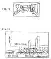
- Fig. 13shows an example of the histogram for a picture as illustrated in Fig. 12.
- the programgoes to a step S117 where data of the histogram of the first division are read.
- a deviation amount at this momentis detected and at a step S119 the distance to the object is calculated from this deviation amount according to the aforementioned equation (3).
- the histogramis started to be surveyed from the larger deviation amount towards the smaller deviation amount.
- the frequency dataexceeds a threshold value for the first time
- the deviation amount of this moment and the distance calculated from the deviation amountis detected as a first distance (Z1) in this division.
- the survey of the histogramcontinues and when the frequency data exceeds again the threshold value after the frequency goes down below the threshold value, the calculated distance is detected as a second distance (Z2). Further, the survey continues and a third and fourth distances are detected.
- the number of datais almost zero where there is no object, since most false data are deleted by the group filter.
- the relationship between the distribution of data and the existence or nonexistence of an objectis visualized and one histogram can tell that the a plurality of objects exist in a given direction. For example, as shown in Fig. 12, it is possible to detect a pedestrian, a forward vehicle and a person riding a bike simultaneously. Under the condition illustrated in Fig. 12, the prior art can not detect a plurality of objects simultaneously, because only the forward vehicle that shows a maximum frequency in the histogram is detected and other objects are neglected.
- the threshold value for distinguishing between the false data and the real data (real objects)can be established to be smaller than that of the prior art and as a result it is possible to detect objects of small size, objects which are difficult to be imaged under such adverse conditions as night and the like or objects whose distance data are insufficient.
- the programproceeds from the step S119 to a step S120 where these distances are written onto the memory and at a step S121 it is checked whether or not the process reaches the last division. If the process has not reached the last division, the program goes to the step S122 where the histogram data of the next division are read and returns to the step S118. When it is judged at the step S121 that the process has reached the last division, the program is finished.
- the division of the distance imagesince the division of the distance image has almost no false data, its width can be made substantially smaller (theoretically, up to the width of one picture element)than that of the prior art and as a result the three-dimensional positional resolution of the detected object can be enhanced, thereby an unevenness, protuberances or indents of the object surface can be detected.
- FIG. 14This drawing is a top view showing on an X - Z plane the detected images of a pedestrian, a plantation, a forward vehicle, a person on the bike, a wall and the like as shown in Fig. 14.
- the vehicle observation apparatuscan have a high three-dimensional resolution due to a thinner division of the distance image than that of the conventional arts in preparing the histogram for detecting objects, thereby detailed configurations of objects can be detected.
- the existence of objectscan be known from the histogram more accurately and as a result the positions of a plurality of objects can be detected simultaneously in the forward direction. Further, since the threshold value for discriminating between the false data and the real data can be lowered, small objects or obscure objects can be detected, thereby more sophisticated, more precise and more reliable surrounding information can be obtained.
Landscapes
- Engineering & Computer Science (AREA)
- Physics & Mathematics (AREA)
- General Physics & Mathematics (AREA)
- Multimedia (AREA)
- Theoretical Computer Science (AREA)
- Signal Processing (AREA)
- Computer Vision & Pattern Recognition (AREA)
- Traffic Control Systems (AREA)
- Image Analysis (AREA)
- Image Processing (AREA)
- Length Measuring Devices By Optical Means (AREA)
- Measurement Of Optical Distance (AREA)
- Closed-Circuit Television Systems (AREA)
Abstract
Description
Case 1.- Dpa ≅ Dpb and Dpa ≅ Dpc
Case 2.- Dpa ≅ Dpb and Dpa ≠ Dpc
- Case 3.
- Dpa ≠ Dpb and Dpa ≅ Dpc
Case 4.- Dpa ≠ Dpb and Dpa ≠ Dpc and Dpa ≅ Dpd
Case 5.- Dpa ≠ Dpb and Dpa ≠ Dpc and Dpa ≠ Dpd and Dpa ≅ Dpe
- Case 6.
- Dpa ≠ Dpb and Dpa ≠ Dpc and Dpa ≠ Dpd and Dpa ≠ Dpe
Case 1;- This case is divided into two cases.
Case 2;- Unconditionally, the block "A" is put into the group of the block"B"
- Case 3;
- Unconditionally, the block "A" is put into the group of the block"C" .
Case 4;- The block "A" is put into a new group.
Case 5;- The block "A" is put into a new group.
- Case 6;
- The block "A" is put into a group "0" (isolated).
Claims (5)
- A vehicle monitoring apparatus for obtaining a distanceimage including an image data and a three-dimensional distance information andfor monitoring surrounding conditions on the basis of said distance image,comprising:means for dividing said distance image into a plurality of blockscomposed of at least one picture element;means for collecting said blocks having a similar distance data andfor grouping said blocks into an independent group if said blocks include imagedata;means for calculating an area size of said independent group;means for extracting said image data as an object data if said areasize of said group is larger than a predetermined value and for discarding saidimage data as a false data if said area size is smaller than said predeterminedvalue;means for preparing a histogram having a lateral axis representinga deviation amount and a longitudinal axis representing a frequency correspondingto a number of said image data; andmeans for detecting an object and a distance to said object bydeleting said frequency having a smaller number of said image data than athreshold value along said lateral axis on said histogram.
- A vehicle monitoring apparatus as claimed in claim 1,whereinwhen said block has a similar distance to said adjacent blockswhose group number is known, said block is grouped into the same group as saidadjacent blocks and when said block has a similar distance to said adjacent blockswhose group number is unknown, said block is grouped into a group denoted bya new number.
- A vehicle monitoring apparatus as claimed in claim 1 orclaim 2, whereinsaid distance image is divided into lattice-like divisions and saidhistogram is prepared for each of said divisions.
- A vehicle monitoring apparatus as claimed in any of claims1 to 3, further comprising:a group number memory for memorizing a number of said groupto which said image data belongs and a group area memory for memorizing anumber of said image data to which each of said groups belong as an area size.
- A vehicle comprising a vehicle monitoring apparatus asclaimed in any of the preceding claims.
Applications Claiming Priority (3)
| Application Number | Priority Date | Filing Date | Title |
|---|---|---|---|
| JP86877/97 | 1997-04-04 | ||
| JP8687797 | 1997-04-04 | ||
| JP08687797AJP3337197B2 (en) | 1997-04-04 | 1997-04-04 | Outside monitoring device |
Publications (3)
| Publication Number | Publication Date |
|---|---|
| EP0874331A2true EP0874331A2 (en) | 1998-10-28 |
| EP0874331A3 EP0874331A3 (en) | 2004-03-17 |
| EP0874331B1 EP0874331B1 (en) | 2014-09-17 |
Family
ID=13899074
Family Applications (1)
| Application Number | Title | Priority Date | Filing Date |
|---|---|---|---|
| EP98302484.5AExpired - LifetimeEP0874331B1 (en) | 1997-04-04 | 1998-03-31 | Vehicle monitoring apparatus |
Country Status (3)
| Country | Link |
|---|---|
| US (1) | US6122597A (en) |
| EP (1) | EP0874331B1 (en) |
| JP (1) | JP3337197B2 (en) |
Cited By (25)
| Publication number | Priority date | Publication date | Assignee | Title |
|---|---|---|---|---|
| WO2000077736A1 (en)* | 1999-06-11 | 2000-12-21 | Daimlerchrysler Ag | Method of detecting objects within a wide range of a road vehicle |
| EP1396833A1 (en)* | 2002-09-05 | 2004-03-10 | Honda Giken Kogyo Kabushiki Kaisha | Vehicle control system, program and method |
| EP0933725A3 (en)* | 1998-01-30 | 2004-05-06 | Fuji Jukogyo Kabushiki Kaisha | Vehicle surroundings monitoring apparatus |
| US6775395B2 (en) | 2000-03-27 | 2004-08-10 | Honda Giken Kogyo Kabushiki Kaisha | Object recognition system |
| DE10310849A1 (en)* | 2003-03-11 | 2004-09-30 | Inb Vision Ag | Procedures to measure a distance of objects, e.g. for moving vehicles and/or position regulation, determining the photo-gram-metric distances or positions from objects, by evaluation of a stereoscopic picture pair |
| DE102004052347A1 (en)* | 2004-10-28 | 2006-05-04 | Daimlerchrysler Ag | Environment information collecting method for motor vehicle, involves assigning evidence-histogram with matrix to sensors, and registering values rendering transverse-distance of object normal to vehicle moving direction in fields of matrix |
| DE102005000775A1 (en)* | 2005-01-05 | 2006-07-13 | Lear Corporation Gmbh & Co. Kg | Driver assistance system for automobiles for obstruction identification reduces amount of data processing for increased speed |
| EP1725975A4 (en)* | 2004-02-17 | 2007-03-21 | Honda Motor Co Ltd | Method, apparatus and program for detecting an object |
| EP2037408A1 (en)* | 2007-09-14 | 2009-03-18 | Saab Ab | Method, computer program and device for determining the risk of midair collision |
| DE10029423B4 (en)* | 1999-06-16 | 2011-04-14 | Honda Giken Kogyo K.K. | Object recognition system |
| US8917169B2 (en) | 1993-02-26 | 2014-12-23 | Magna Electronics Inc. | Vehicular vision system |
| US8993951B2 (en) | 1996-03-25 | 2015-03-31 | Magna Electronics Inc. | Driver assistance system for a vehicle |
| US9008369B2 (en) | 2004-04-15 | 2015-04-14 | Magna Electronics Inc. | Vision system for vehicle |
| US9193302B2 (en) | 1999-11-04 | 2015-11-24 | Magna Electronics Inc. | Vision system for a vehicle |
| US9233645B2 (en) | 1999-11-04 | 2016-01-12 | Magna Electronics Inc. | Accessory mounting system for a vehicle |
| US9266474B2 (en) | 2004-08-18 | 2016-02-23 | Magna Electronics Inc. | Accessory system for vehicle |
| DE10141924B4 (en)* | 2000-08-29 | 2016-05-04 | Toyota Jidosha Kabushiki Kaisha | Driving controller and driving control method |
| US9436880B2 (en) | 1999-08-12 | 2016-09-06 | Magna Electronics Inc. | Vehicle vision system |
| US9434314B2 (en) | 1998-04-08 | 2016-09-06 | Donnelly Corporation | Electronic accessory system for a vehicle |
| US9643605B2 (en) | 2002-05-03 | 2017-05-09 | Magna Electronics Inc. | Vision system for vehicle |
| US9862323B2 (en) | 2002-01-31 | 2018-01-09 | Magna Electronics Inc. | Vehicle accessory system |
| US10071676B2 (en) | 2006-08-11 | 2018-09-11 | Magna Electronics Inc. | Vision system for vehicle |
| EP3258214A4 (en)* | 2015-02-12 | 2019-03-13 | Hitachi Automotive Systems, Ltd. | OBJECT DETECTION DEVICE |
| US10331960B2 (en)* | 2017-05-10 | 2019-06-25 | Fotonation Limited | Methods for detecting, identifying and displaying object information with a multi-camera vision system |
| US12174297B2 (en) | 2019-09-25 | 2024-12-24 | Sony Semiconductor Solutions Corporation | Distance measurement device, method of controlling distance measurement device, and electronic apparatus |
Families Citing this family (102)
| Publication number | Priority date | Publication date | Assignee | Title |
|---|---|---|---|---|
| US5910854A (en) | 1993-02-26 | 1999-06-08 | Donnelly Corporation | Electrochromic polymeric solid films, manufacturing electrochromic devices using such solid films, and processes for making such solid films and devices |
| US5668663A (en) | 1994-05-05 | 1997-09-16 | Donnelly Corporation | Electrochromic mirrors and devices |
| US6891563B2 (en) | 1996-05-22 | 2005-05-10 | Donnelly Corporation | Vehicular vision system |
| US6124886A (en) | 1997-08-25 | 2000-09-26 | Donnelly Corporation | Modular rearview mirror assembly |
| US6326613B1 (en) | 1998-01-07 | 2001-12-04 | Donnelly Corporation | Vehicle interior mirror assembly adapted for containing a rain sensor |
| US8294975B2 (en) | 1997-08-25 | 2012-10-23 | Donnelly Corporation | Automotive rearview mirror assembly |
| US6172613B1 (en) | 1998-02-18 | 2001-01-09 | Donnelly Corporation | Rearview mirror assembly incorporating vehicle information display |
| US8288711B2 (en) | 1998-01-07 | 2012-10-16 | Donnelly Corporation | Interior rearview mirror system with forwardly-viewing camera and a control |
| US6278377B1 (en) | 1999-08-25 | 2001-08-21 | Donnelly Corporation | Indicator for vehicle accessory |
| US6693517B2 (en) | 2000-04-21 | 2004-02-17 | Donnelly Corporation | Vehicle mirror assembly communicating wirelessly with vehicle accessories and occupants |
| US6477464B2 (en) | 2000-03-09 | 2002-11-05 | Donnelly Corporation | Complete mirror-based global-positioning system (GPS) navigation solution |
| US6329925B1 (en) | 1999-11-24 | 2001-12-11 | Donnelly Corporation | Rearview mirror assembly with added feature modular display |
| JP2000306195A (en)* | 1999-04-22 | 2000-11-02 | Matsushita Electric Ind Co Ltd | Vehicle behavior detection device using lane markers |
| JP4394780B2 (en)* | 1999-10-08 | 2010-01-06 | クラリオン株式会社 | Mobile body information recording device |
| JP2001195699A (en)* | 2000-01-14 | 2001-07-19 | Yazaki Corp | VEHICLE PERIPHERAL MONITOR AND RECORDING MEDIUM CONTAINING VEHICLE COLLISION DANGER JUDGING PROCESSING PROGRAM |
| US6515597B1 (en)* | 2000-01-31 | 2003-02-04 | Matsushita Electric Industrial Co. Ltd. | Vicinity display for car |
| US7167796B2 (en) | 2000-03-09 | 2007-01-23 | Donnelly Corporation | Vehicle navigation system for use with a telematics system |
| US7370983B2 (en) | 2000-03-02 | 2008-05-13 | Donnelly Corporation | Interior mirror assembly with display |
| US7581859B2 (en) | 2005-09-14 | 2009-09-01 | Donnelly Corp. | Display device for exterior rearview mirror |
| US7255451B2 (en) | 2002-09-20 | 2007-08-14 | Donnelly Corporation | Electro-optic mirror cell |
| AU2002251807A1 (en) | 2001-01-23 | 2002-08-19 | Donnelly Corporation | Improved vehicular lighting system for a mirror assembly |
| US20020134151A1 (en)* | 2001-02-05 | 2002-09-26 | Matsushita Electric Industrial Co., Ltd. | Apparatus and method for measuring distances |
| JP4615139B2 (en)* | 2001-03-30 | 2011-01-19 | 本田技研工業株式会社 | Vehicle periphery monitoring device |
| US6493620B2 (en)* | 2001-04-18 | 2002-12-10 | Eaton Corporation | Motor vehicle occupant detection system employing ellipse shape models and bayesian classification |
| JP3880837B2 (en)* | 2001-11-02 | 2007-02-14 | 富士重工業株式会社 | Outside monitoring device |
| US20030095080A1 (en)* | 2001-11-19 | 2003-05-22 | Koninklijke Philips Electronics N.V. | Method and system for improving car safety using image-enhancement |
| US6918674B2 (en) | 2002-05-03 | 2005-07-19 | Donnelly Corporation | Vehicle rearview mirror system |
| US7329013B2 (en) | 2002-06-06 | 2008-02-12 | Donnelly Corporation | Interior rearview mirror system with compass |
| AU2003237424A1 (en) | 2002-06-06 | 2003-12-22 | Donnelly Corporation | Interior rearview mirror system with compass |
| JP4176430B2 (en)* | 2002-09-18 | 2008-11-05 | 富士重工業株式会社 | Outside-of-vehicle monitoring device and travel control device equipped with this out-of-vehicle monitoring device |
| US7310177B2 (en) | 2002-09-20 | 2007-12-18 | Donnelly Corporation | Electro-optic reflective element assembly |
| WO2004103772A2 (en) | 2003-05-19 | 2004-12-02 | Donnelly Corporation | Mirror assembly for vehicle |
| WO2004026633A2 (en) | 2002-09-20 | 2004-04-01 | Donnelly Corporation | Mirror reflective element assembly |
| JP4311107B2 (en)* | 2003-08-08 | 2009-08-12 | オムロン株式会社 | Three-dimensional object recognition device and setting method thereof |
| JP3949628B2 (en)* | 2003-09-02 | 2007-07-25 | 本田技研工業株式会社 | Vehicle periphery monitoring device |
| US7446924B2 (en) | 2003-10-02 | 2008-11-04 | Donnelly Corporation | Mirror reflective element assembly including electronic component |
| US7308341B2 (en) | 2003-10-14 | 2007-12-11 | Donnelly Corporation | Vehicle communication system |
| US7356408B2 (en)* | 2003-10-17 | 2008-04-08 | Fuji Jukogyo Kabushiki Kaisha | Information display apparatus and information display method |
| CN1292941C (en)* | 2004-05-24 | 2007-01-03 | 刘新颜 | Rear-view device of automobile |
| EP1779295A4 (en)* | 2004-07-26 | 2012-07-04 | Automotive Systems Lab | Vulnerable road user protection system |
| US7639841B2 (en)* | 2004-12-20 | 2009-12-29 | Siemens Corporation | System and method for on-road detection of a vehicle using knowledge fusion |
| EP1883855B1 (en) | 2005-05-16 | 2011-07-20 | Donnelly Corporation | Vehicle mirror assembly with indicia at reflective element |
| EP1949666B1 (en) | 2005-11-01 | 2013-07-17 | Magna Mirrors of America, Inc. | Interior rearview mirror with display |
| US8194132B2 (en) | 2006-01-20 | 2012-06-05 | Old World Industries, Llc | System for monitoring an area adjacent a vehicle |
| CN101401024B (en) | 2006-03-09 | 2016-03-16 | 金泰克斯公司 | Comprise the vehicle rearview assembly of high intensity display |
| JP4632987B2 (en)* | 2006-03-28 | 2011-02-16 | 株式会社パスコ | Road image analysis apparatus and road image analysis method |
| JP5164351B2 (en)* | 2006-09-07 | 2013-03-21 | 富士重工業株式会社 | Object detection apparatus and object detection method |
| GB2450478A (en)* | 2007-06-20 | 2008-12-31 | Sony Uk Ltd | A security device and system |
| JP4876080B2 (en) | 2008-01-25 | 2012-02-15 | 富士重工業株式会社 | Environment recognition device |
| US8154418B2 (en) | 2008-03-31 | 2012-04-10 | Magna Mirrors Of America, Inc. | Interior rearview mirror system |
| US9487144B2 (en) | 2008-10-16 | 2016-11-08 | Magna Mirrors Of America, Inc. | Interior mirror assembly with display |
| US20100289874A1 (en)* | 2009-05-15 | 2010-11-18 | Fuhua Cheng | Square tube mirror-based imaging system |
| US8964004B2 (en) | 2010-06-18 | 2015-02-24 | Amchael Visual Technology Corporation | Three channel reflector imaging system |
| US9058247B2 (en)* | 2010-09-08 | 2015-06-16 | Toyota Jidosha Kabushiki Kaisha | Risk potential calculation apparatus |
| JP5569365B2 (en)* | 2010-11-30 | 2014-08-13 | アイシン・エィ・ダブリュ株式会社 | Guide device, guide method, and guide program |
| JP5472928B2 (en)* | 2010-12-10 | 2014-04-16 | 株式会社東芝 | Object detection apparatus and method |
| US8648808B2 (en) | 2011-09-19 | 2014-02-11 | Amchael Visual Technology Corp. | Three-dimensional human-computer interaction system that supports mouse operations through the motion of a finger and an operation method thereof |
| US9019352B2 (en) | 2011-11-21 | 2015-04-28 | Amchael Visual Technology Corp. | Two-parallel-channel reflector with focal length and disparity control |
| JP5757900B2 (en)* | 2012-03-07 | 2015-08-05 | 日立オートモティブシステムズ株式会社 | Vehicle travel control device |
| US9019603B2 (en) | 2012-03-22 | 2015-04-28 | Amchael Visual Technology Corp. | Two-parallel-channel reflector with focal length and disparity control |
| US8824733B2 (en)* | 2012-03-26 | 2014-09-02 | Tk Holdings Inc. | Range-cued object segmentation system and method |
| US8768007B2 (en) | 2012-03-26 | 2014-07-01 | Tk Holdings Inc. | Method of filtering an image |
| US8879139B2 (en) | 2012-04-24 | 2014-11-04 | Gentex Corporation | Display mirror assembly |
| US9557634B2 (en) | 2012-07-05 | 2017-01-31 | Amchael Visual Technology Corporation | Two-channel reflector based single-lens 2D/3D camera with disparity and convergence angle control |
| JP6060612B2 (en)* | 2012-10-17 | 2017-01-18 | 株式会社リコー | Moving surface situation recognition device, moving object, and program |
| WO2014070448A1 (en) | 2012-10-31 | 2014-05-08 | Tk Holdings, Inc. | Vehicular path sensing system and method |
| CN104823218A (en)* | 2012-12-03 | 2015-08-05 | 哈曼国际工业有限公司 | System and method for detecting pedestrians using a single normal camera |
| WO2014152470A2 (en) | 2013-03-15 | 2014-09-25 | Tk Holdings, Inc. | Path sensing using structured lighting |
| KR101881346B1 (en) | 2013-03-15 | 2018-07-24 | 젠텍스 코포레이션 | Display mirror assembly |
| JP2016534915A (en) | 2013-09-24 | 2016-11-10 | ジェンテックス コーポレイション | Display mirror assembly |
| US9511715B2 (en) | 2014-01-31 | 2016-12-06 | Gentex Corporation | Backlighting assembly for display for reducing cross-hatching |
| US10705332B2 (en) | 2014-03-21 | 2020-07-07 | Gentex Corporation | Tri-modal display mirror assembly |
| KR101894262B1 (en) | 2014-04-01 | 2018-09-04 | 젠텍스 코포레이션 | Automatic display mirror assembly |
| KR101631439B1 (en)* | 2014-05-29 | 2016-06-17 | 엘지전자 주식회사 | Camera and Vehicle including the same |
| US9694751B2 (en) | 2014-09-19 | 2017-07-04 | Gentex Corporation | Rearview assembly |
| WO2016073848A1 (en) | 2014-11-07 | 2016-05-12 | Gentex Corporation | Full display mirror actuator |
| US10071689B2 (en) | 2014-11-13 | 2018-09-11 | Gentex Corporation | Rearview mirror system with a display |
| US10131279B2 (en) | 2014-12-03 | 2018-11-20 | Gentex Corporation | Display mirror assembly with an RF shield bezel |
| USD746744S1 (en) | 2014-12-05 | 2016-01-05 | Gentex Corporation | Rearview device |
| US9744907B2 (en) | 2014-12-29 | 2017-08-29 | Gentex Corporation | Vehicle vision system having adjustable displayed field of view |
| US9720278B2 (en) | 2015-01-22 | 2017-08-01 | Gentex Corporation | Low cost optical film stack |
| JP6564218B2 (en)* | 2015-03-27 | 2019-08-21 | 株式会社Subaru | Outside environment recognition device |
| JP2018513810A (en) | 2015-04-20 | 2018-05-31 | ジェンテックス コーポレイション | Rear view assembly with decoration |
| EP3297870B1 (en) | 2015-05-18 | 2020-02-05 | Gentex Corporation | Full display rearview device |
| WO2016209877A1 (en) | 2015-06-22 | 2016-12-29 | Gentex Corporation | System and method for processing streamed video images to correct for flicker of amplitude-modulated lights |
| USD798207S1 (en) | 2015-10-30 | 2017-09-26 | Gentex Corporation | Rearview mirror assembly |
| USD797627S1 (en) | 2015-10-30 | 2017-09-19 | Gentex Corporation | Rearview mirror device |
| CN108349436B (en) | 2015-10-30 | 2019-12-20 | 金泰克斯公司 | Rear-view device |
| WO2017075420A1 (en) | 2015-10-30 | 2017-05-04 | Gentex Corporation | Toggle paddle |
| USD800618S1 (en) | 2015-11-02 | 2017-10-24 | Gentex Corporation | Toggle paddle for a rear view device |
| JP6623729B2 (en)* | 2015-12-04 | 2019-12-25 | 株式会社ソシオネクスト | Ranging systems, moving objects and parts |
| USD845851S1 (en) | 2016-03-31 | 2019-04-16 | Gentex Corporation | Rearview device |
| USD817238S1 (en) | 2016-04-29 | 2018-05-08 | Gentex Corporation | Rearview device |
| US10025138B2 (en) | 2016-06-06 | 2018-07-17 | Gentex Corporation | Illuminating display with light gathering structure |
| USD809984S1 (en) | 2016-12-07 | 2018-02-13 | Gentex Corporation | Rearview assembly |
| USD854473S1 (en) | 2016-12-16 | 2019-07-23 | Gentex Corporation | Rearview assembly |
| KR20190104990A (en) | 2016-12-30 | 2019-09-11 | 젠텍스 코포레이션 | Full display mirror with instant custom spotter view |
| EP3595931A4 (en) | 2017-03-17 | 2020-01-22 | Gentex Corporation | REVIEW REVERSE CAMERA WITH TWO |
| JP6891792B2 (en)* | 2017-12-15 | 2021-06-18 | 富士通株式会社 | Measurement program, measuring device and measuring method |
| JP7179687B2 (en)* | 2019-06-17 | 2022-11-29 | 株式会社東芝 | Obstacle detector |
| CN111540201B (en)* | 2020-04-23 | 2021-03-30 | 山东大学 | Real-time estimation method and system of vehicle queue length based on roadside lidar |
| US11994272B2 (en) | 2021-08-20 | 2024-05-28 | Gentex Corporation | Lighting assembly and illumination system having a lighting assembly |
Family Cites Families (7)
| Publication number | Priority date | Publication date | Assignee | Title |
|---|---|---|---|---|
| JP2729417B2 (en)* | 1991-07-15 | 1998-03-18 | 株式会社テイエルブイ | Decompression evaporative cooling equipment |
| JP2536986B2 (en)* | 1991-12-09 | 1996-09-25 | 三菱電機株式会社 | Inter-vehicle distance detector |
| JPH05265547A (en)* | 1992-03-23 | 1993-10-15 | Fuji Heavy Ind Ltd | On-vehicle outside monitoring device |
| US5515448A (en)* | 1992-07-28 | 1996-05-07 | Yazaki Corporation | Distance measuring apparatus of a target tracking type |
| US5592567A (en)* | 1992-11-10 | 1997-01-07 | Siemens Aktiengesellschaft | Method for detecting and separating the shadow of moving objects in a sequence of digital images |
| JP3522317B2 (en)* | 1993-12-27 | 2004-04-26 | 富士重工業株式会社 | Travel guide device for vehicles |
| US5825915A (en)* | 1995-09-12 | 1998-10-20 | Matsushita Electric Industrial Co., Ltd. | Object detecting apparatus in which the position of a planar object is estimated by using hough transform |
- 1997
- 1997-04-04JPJP08687797Apatent/JP3337197B2/ennot_activeExpired - Lifetime
- 1998
- 1998-03-26USUS09/048,332patent/US6122597A/ennot_activeExpired - Lifetime
- 1998-03-31EPEP98302484.5Apatent/EP0874331B1/ennot_activeExpired - Lifetime
Cited By (59)
| Publication number | Priority date | Publication date | Assignee | Title |
|---|---|---|---|---|
| US8917169B2 (en) | 1993-02-26 | 2014-12-23 | Magna Electronics Inc. | Vehicular vision system |
| US8993951B2 (en) | 1996-03-25 | 2015-03-31 | Magna Electronics Inc. | Driver assistance system for a vehicle |
| EP0933725A3 (en)* | 1998-01-30 | 2004-05-06 | Fuji Jukogyo Kabushiki Kaisha | Vehicle surroundings monitoring apparatus |
| US9434314B2 (en) | 1998-04-08 | 2016-09-06 | Donnelly Corporation | Electronic accessory system for a vehicle |
| WO2000077736A1 (en)* | 1999-06-11 | 2000-12-21 | Daimlerchrysler Ag | Method of detecting objects within a wide range of a road vehicle |
| US7046822B1 (en) | 1999-06-11 | 2006-05-16 | Daimlerchrysler Ag | Method of detecting objects within a wide range of a road vehicle |
| DE10029423B4 (en)* | 1999-06-16 | 2011-04-14 | Honda Giken Kogyo K.K. | Object recognition system |
| US9436880B2 (en) | 1999-08-12 | 2016-09-06 | Magna Electronics Inc. | Vehicle vision system |
| US9233645B2 (en) | 1999-11-04 | 2016-01-12 | Magna Electronics Inc. | Accessory mounting system for a vehicle |
| US9193302B2 (en) | 1999-11-04 | 2015-11-24 | Magna Electronics Inc. | Vision system for a vehicle |
| US9637053B2 (en) | 1999-11-04 | 2017-05-02 | Magna Electronics Inc. | Accessory mounting system for a vehicle |
| US10427604B2 (en) | 2000-03-02 | 2019-10-01 | Magna Electronics Inc. | Vision system for a vehicle |
| US9843777B2 (en) | 2000-03-02 | 2017-12-12 | Magna Electronics Inc. | Cabin monitoring system for a vehicle |
| US10059265B2 (en) | 2000-03-02 | 2018-08-28 | Magna Electronics Inc. | Vision system for a vehicle |
| DE10115080B4 (en)* | 2000-03-27 | 2007-07-19 | Honda Giken Kogyo K.K. | Object recognition system |
| US6775395B2 (en) | 2000-03-27 | 2004-08-10 | Honda Giken Kogyo Kabushiki Kaisha | Object recognition system |
| DE10141924B4 (en)* | 2000-08-29 | 2016-05-04 | Toyota Jidosha Kabushiki Kaisha | Driving controller and driving control method |
| US9862323B2 (en) | 2002-01-31 | 2018-01-09 | Magna Electronics Inc. | Vehicle accessory system |
| US10543786B2 (en) | 2002-01-31 | 2020-01-28 | Magna Electronics Inc. | Vehicle camera system |
| US10351135B2 (en) | 2002-05-03 | 2019-07-16 | Magna Electronics Inc. | Vehicular control system using cameras and radar sensor |
| US10683008B2 (en) | 2002-05-03 | 2020-06-16 | Magna Electronics Inc. | Vehicular driving assist system using forward-viewing camera |
| US11203340B2 (en) | 2002-05-03 | 2021-12-21 | Magna Electronics Inc. | Vehicular vision system using side-viewing camera |
| US10118618B2 (en) | 2002-05-03 | 2018-11-06 | Magna Electronics Inc. | Vehicular control system using cameras and radar sensor |
| US9834216B2 (en) | 2002-05-03 | 2017-12-05 | Magna Electronics Inc. | Vehicular control system using cameras and radar sensor |
| US9643605B2 (en) | 2002-05-03 | 2017-05-09 | Magna Electronics Inc. | Vision system for vehicle |
| EP1396833A1 (en)* | 2002-09-05 | 2004-03-10 | Honda Giken Kogyo Kabushiki Kaisha | Vehicle control system, program and method |
| DE10310849B4 (en)* | 2003-03-11 | 2009-01-02 | Inb Vision Ag | Method for photogrammetric distance and / or position determination |
| DE10310849A1 (en)* | 2003-03-11 | 2004-09-30 | Inb Vision Ag | Procedures to measure a distance of objects, e.g. for moving vehicles and/or position regulation, determining the photo-gram-metric distances or positions from objects, by evaluation of a stereoscopic picture pair |
| EP1725975A4 (en)* | 2004-02-17 | 2007-03-21 | Honda Motor Co Ltd | Method, apparatus and program for detecting an object |
| US7224831B2 (en) | 2004-02-17 | 2007-05-29 | Honda Motor Co. | Method, apparatus and program for detecting an object |
| US10015452B1 (en) | 2004-04-15 | 2018-07-03 | Magna Electronics Inc. | Vehicular control system |
| US11503253B2 (en) | 2004-04-15 | 2022-11-15 | Magna Electronics Inc. | Vehicular control system with traffic lane detection |
| US9948904B2 (en) | 2004-04-15 | 2018-04-17 | Magna Electronics Inc. | Vision system for vehicle |
| US11847836B2 (en) | 2004-04-15 | 2023-12-19 | Magna Electronics Inc. | Vehicular control system with road curvature determination |
| US9609289B2 (en) | 2004-04-15 | 2017-03-28 | Magna Electronics Inc. | Vision system for vehicle |
| US10735695B2 (en) | 2004-04-15 | 2020-08-04 | Magna Electronics Inc. | Vehicular control system with traffic lane detection |
| US10110860B1 (en) | 2004-04-15 | 2018-10-23 | Magna Electronics Inc. | Vehicular control system |
| US9008369B2 (en) | 2004-04-15 | 2015-04-14 | Magna Electronics Inc. | Vision system for vehicle |
| US10187615B1 (en) | 2004-04-15 | 2019-01-22 | Magna Electronics Inc. | Vehicular control system |
| US9736435B2 (en) | 2004-04-15 | 2017-08-15 | Magna Electronics Inc. | Vision system for vehicle |
| US10306190B1 (en) | 2004-04-15 | 2019-05-28 | Magna Electronics Inc. | Vehicular control system |
| US10462426B2 (en) | 2004-04-15 | 2019-10-29 | Magna Electronics Inc. | Vehicular control system |
| US10773724B2 (en) | 2004-08-18 | 2020-09-15 | Magna Electronics Inc. | Accessory system for vehicle |
| US9266474B2 (en) | 2004-08-18 | 2016-02-23 | Magna Electronics Inc. | Accessory system for vehicle |
| DE102004052347A1 (en)* | 2004-10-28 | 2006-05-04 | Daimlerchrysler Ag | Environment information collecting method for motor vehicle, involves assigning evidence-histogram with matrix to sensors, and registering values rendering transverse-distance of object normal to vehicle moving direction in fields of matrix |
| DE102005000775A1 (en)* | 2005-01-05 | 2006-07-13 | Lear Corporation Gmbh & Co. Kg | Driver assistance system for automobiles for obstruction identification reduces amount of data processing for increased speed |
| DE102005000775B4 (en)* | 2005-01-05 | 2006-09-21 | Lear Corporation Gmbh & Co. Kg | Method for monitoring an object space from a motor vehicle |
| US11623559B2 (en) | 2006-08-11 | 2023-04-11 | Magna Electronics Inc. | Vehicular forward viewing image capture system |
| US10071676B2 (en) | 2006-08-11 | 2018-09-11 | Magna Electronics Inc. | Vision system for vehicle |
| US10787116B2 (en) | 2006-08-11 | 2020-09-29 | Magna Electronics Inc. | Adaptive forward lighting system for vehicle comprising a control that adjusts the headlamp beam in response to processing of image data captured by a camera |
| US11148583B2 (en) | 2006-08-11 | 2021-10-19 | Magna Electronics Inc. | Vehicular forward viewing image capture system |
| US11396257B2 (en) | 2006-08-11 | 2022-07-26 | Magna Electronics Inc. | Vehicular forward viewing image capture system |
| US11951900B2 (en) | 2006-08-11 | 2024-04-09 | Magna Electronics Inc. | Vehicular forward viewing image capture system |
| US7969289B2 (en) | 2007-09-14 | 2011-06-28 | Saab Ab | Method, computer program and device for determining the risk of midair collision |
| EP2037408A1 (en)* | 2007-09-14 | 2009-03-18 | Saab Ab | Method, computer program and device for determining the risk of midair collision |
| US10627228B2 (en) | 2015-02-12 | 2020-04-21 | Hitachi Automotive Systems, Ltd. | Object detection device |
| EP3258214A4 (en)* | 2015-02-12 | 2019-03-13 | Hitachi Automotive Systems, Ltd. | OBJECT DETECTION DEVICE |
| US10331960B2 (en)* | 2017-05-10 | 2019-06-25 | Fotonation Limited | Methods for detecting, identifying and displaying object information with a multi-camera vision system |
| US12174297B2 (en) | 2019-09-25 | 2024-12-24 | Sony Semiconductor Solutions Corporation | Distance measurement device, method of controlling distance measurement device, and electronic apparatus |
Also Published As
| Publication number | Publication date |
|---|---|
| EP0874331B1 (en) | 2014-09-17 |
| US6122597A (en) | 2000-09-19 |
| JP3337197B2 (en) | 2002-10-21 |
| EP0874331A3 (en) | 2004-03-17 |
| JPH10285582A (en) | 1998-10-23 |
Similar Documents
| Publication | Publication Date | Title |
|---|---|---|
| EP0874331B1 (en) | Vehicle monitoring apparatus | |
| US6370261B1 (en) | Vehicle surroundings monitoring apparatus | |
| JP3349060B2 (en) | Outside monitoring device | |
| JP3596314B2 (en) | Object edge position measuring device and moving object traffic judging device | |
| JP4650079B2 (en) | Object detection apparatus and method | |
| US7046822B1 (en) | Method of detecting objects within a wide range of a road vehicle | |
| US6731777B1 (en) | Object recognition system | |
| JP3315054B2 (en) | Outside monitoring device | |
| CN102303609B (en) | Lane departure early warning system and method | |
| JPH1139596A (en) | Outside monitoring device | |
| JP4638369B2 (en) | Lane position detector | |
| EP2963634B1 (en) | Stereo camera device | |
| CN104916163A (en) | Parking space detection method | |
| CN102303563B (en) | Front vehicle collision early warning system and method | |
| JPH10283462A (en) | Outer-vehicle monitoring device | |
| JP2007309799A (en) | In-vehicle ranging device | |
| CN110843786A (en) | Method and system for determining and displaying a water-engaging condition and vehicle having such a system | |
| JPH08156723A (en) | Vehicle obstacle detection device | |
| JP4956099B2 (en) | Wall detector | |
| EP1982890B1 (en) | Automotive environment monitoring device, vehicle with the automotive environment monitoring device | |
| JP5746996B2 (en) | Road environment recognition device | |
| CN202600727U (en) | Sidewall detection apparatus | |
| KR100976142B1 (en) | Vehicle Detection Method | |
| JP3697435B2 (en) | Outside monitoring device | |
| JPH0979821A (en) | Obstacle recognizing device |
Legal Events
| Date | Code | Title | Description |
|---|---|---|---|
| PUAI | Public reference made under article 153(3) epc to a published international application that has entered the european phase | Free format text:ORIGINAL CODE: 0009012 | |
| AK | Designated contracting states | Kind code of ref document:A2 Designated state(s):AT BE CH DE DK ES FI FR GB GR IE IT LI LU MC NL PT SE | |
| AX | Request for extension of the european patent | Free format text:AL;LT;LV;MK;RO;SI | |
| PUAL | Search report despatched | Free format text:ORIGINAL CODE: 0009013 | |
| AK | Designated contracting states | Kind code of ref document:A3 Designated state(s):AT BE CH DE DK ES FI FR GB GR IE IT LI LU MC NL PT SE | |
| AX | Request for extension of the european patent | Extension state:AL LT LV MK RO SI | |
| RIC1 | Information provided on ipc code assigned before grant | Ipc:7G 06T 7/00 B Ipc:7G 06T 7/60 A | |
| 17P | Request for examination filed | Effective date:20040507 | |
| AKX | Designation fees paid | Designated state(s):DE GB | |
| 17Q | First examination report despatched | Effective date:20041103 | |
| GRAP | Despatch of communication of intention to grant a patent | Free format text:ORIGINAL CODE: EPIDOSNIGR1 | |
| INTG | Intention to grant announced | Effective date:20140409 | |
| GRAS | Grant fee paid | Free format text:ORIGINAL CODE: EPIDOSNIGR3 | |
| GRAA | (expected) grant | Free format text:ORIGINAL CODE: 0009210 | |
| AK | Designated contracting states | Kind code of ref document:B1 Designated state(s):DE GB | |
| REG | Reference to a national code | Ref country code:GB Ref legal event code:FG4D | |
| REG | Reference to a national code | Ref country code:DE Ref legal event code:R081 Ref document number:69843298 Country of ref document:DE Owner name:SUBARU CORPORATION, JP Free format text:FORMER OWNER: FUJI JUKOGYO K.K., TOKIO/TOKYO, JP | |
| REG | Reference to a national code | Ref country code:DE Ref legal event code:R096 Ref document number:69843298 Country of ref document:DE Effective date:20141030 | |
| RAP2 | Party data changed (patent owner data changed or rights of a patent transferred) | Owner name:FUJI JUKOGYO KABUSHIKI KAISHA | |
| REG | Reference to a national code | Ref country code:DE Ref legal event code:R097 Ref document number:69843298 Country of ref document:DE | |
| PLBE | No opposition filed within time limit | Free format text:ORIGINAL CODE: 0009261 | |
| STAA | Information on the status of an ep patent application or granted ep patent | Free format text:STATUS: NO OPPOSITION FILED WITHIN TIME LIMIT | |
| 26N | No opposition filed | Effective date:20150618 | |
| GBPC | Gb: european patent ceased through non-payment of renewal fee | Effective date:20150331 | |
| PG25 | Lapsed in a contracting state [announced via postgrant information from national office to epo] | Ref country code:GB Free format text:LAPSE BECAUSE OF NON-PAYMENT OF DUE FEES Effective date:20150331 | |
| REG | Reference to a national code | Ref country code:DE Ref legal event code:R082 Ref document number:69843298 Country of ref document:DE Representative=s name:VOSSIUS & PARTNER PATENTANWAELTE RECHTSANWAELT, DE Ref country code:DE Ref legal event code:R081 Ref document number:69843298 Country of ref document:DE Owner name:SUBARU CORPORATION, JP Free format text:FORMER OWNER: FUJI JUKOGYO K.K., TOKIO/TOKYO, JP | |
| PGFP | Annual fee paid to national office [announced via postgrant information from national office to epo] | Ref country code:DE Payment date:20170329 Year of fee payment:20 | |
| REG | Reference to a national code | Ref country code:DE Ref legal event code:R071 Ref document number:69843298 Country of ref document:DE |