EP0874191B1 - Optical transmission tube, method for making it and linear illuminant system - Google Patents
Optical transmission tube, method for making it and linear illuminant systemDownload PDFInfo
- Publication number
- EP0874191B1 EP0874191B1EP98303168AEP98303168AEP0874191B1EP 0874191 B1EP0874191 B1EP 0874191B1EP 98303168 AEP98303168 AEP 98303168AEP 98303168 AEP98303168 AEP 98303168AEP 0874191 B1EP0874191 B1EP 0874191B1
- Authority
- EP
- European Patent Office
- Prior art keywords
- cladding
- optical transmission
- light
- core
- tube
- Prior art date
- Legal status (The legal status is an assumption and is not a legal conclusion. Google has not performed a legal analysis and makes no representation as to the accuracy of the status listed.)
- Expired - Lifetime
Links
Images


Classifications
- B—PERFORMING OPERATIONS; TRANSPORTING
- B60—VEHICLES IN GENERAL
- B60Q—ARRANGEMENT OF SIGNALLING OR LIGHTING DEVICES, THE MOUNTING OR SUPPORTING THEREOF OR CIRCUITS THEREFOR, FOR VEHICLES IN GENERAL
- B60Q1/00—Arrangement of optical signalling or lighting devices, the mounting or supporting thereof or circuits therefor
- B60Q1/26—Arrangement of optical signalling or lighting devices, the mounting or supporting thereof or circuits therefor the devices being primarily intended to indicate the vehicle, or parts thereof, or to give signals, to other traffic
- B60Q1/32—Arrangement of optical signalling or lighting devices, the mounting or supporting thereof or circuits therefor the devices being primarily intended to indicate the vehicle, or parts thereof, or to give signals, to other traffic for indicating vehicle sides, e.g. clearance lights
- B60Q1/323—Arrangement of optical signalling or lighting devices, the mounting or supporting thereof or circuits therefor the devices being primarily intended to indicate the vehicle, or parts thereof, or to give signals, to other traffic for indicating vehicle sides, e.g. clearance lights on or for doors
- B—PERFORMING OPERATIONS; TRANSPORTING
- B60—VEHICLES IN GENERAL
- B60Q—ARRANGEMENT OF SIGNALLING OR LIGHTING DEVICES, THE MOUNTING OR SUPPORTING THEREOF OR CIRCUITS THEREFOR, FOR VEHICLES IN GENERAL
- B60Q3/00—Arrangement of lighting devices for vehicle interiors; Lighting devices specially adapted for vehicle interiors
- B60Q3/60—Arrangement of lighting devices for vehicle interiors; Lighting devices specially adapted for vehicle interiors characterised by optical aspects
- B60Q3/62—Arrangement of lighting devices for vehicle interiors; Lighting devices specially adapted for vehicle interiors characterised by optical aspects using light guides
- B60Q3/64—Arrangement of lighting devices for vehicle interiors; Lighting devices specially adapted for vehicle interiors characterised by optical aspects using light guides for a single lighting device
- B—PERFORMING OPERATIONS; TRANSPORTING
- B60—VEHICLES IN GENERAL
- B60Q—ARRANGEMENT OF SIGNALLING OR LIGHTING DEVICES, THE MOUNTING OR SUPPORTING THEREOF OR CIRCUITS THEREFOR, FOR VEHICLES IN GENERAL
- B60Q3/00—Arrangement of lighting devices for vehicle interiors; Lighting devices specially adapted for vehicle interiors
- B60Q3/70—Arrangement of lighting devices for vehicle interiors; Lighting devices specially adapted for vehicle interiors characterised by the purpose
- B60Q3/78—Arrangement of lighting devices for vehicle interiors; Lighting devices specially adapted for vehicle interiors characterised by the purpose for generating luminous strips, e.g. for marking trim component edges
- B—PERFORMING OPERATIONS; TRANSPORTING
- B60—VEHICLES IN GENERAL
- B60Q—ARRANGEMENT OF SIGNALLING OR LIGHTING DEVICES, THE MOUNTING OR SUPPORTING THEREOF OR CIRCUITS THEREFOR, FOR VEHICLES IN GENERAL
- B60Q7/00—Arrangement or adaptation of portable emergency signal devices on vehicles
- G—PHYSICS
- G02—OPTICS
- G02B—OPTICAL ELEMENTS, SYSTEMS OR APPARATUS
- G02B6/00—Light guides; Structural details of arrangements comprising light guides and other optical elements, e.g. couplings
- G02B6/0001—Light guides; Structural details of arrangements comprising light guides and other optical elements, e.g. couplings specially adapted for lighting devices or systems
- G02B6/0005—Light guides; Structural details of arrangements comprising light guides and other optical elements, e.g. couplings specially adapted for lighting devices or systems the light guides being of the fibre type
- G02B6/001—Light guides; Structural details of arrangements comprising light guides and other optical elements, e.g. couplings specially adapted for lighting devices or systems the light guides being of the fibre type the light being emitted along at least a portion of the lateral surface of the fibre
- G—PHYSICS
- G02—OPTICS
- G02B—OPTICAL ELEMENTS, SYSTEMS OR APPARATUS
- G02B6/00—Light guides; Structural details of arrangements comprising light guides and other optical elements, e.g. couplings
- G02B6/02—Optical fibres with cladding with or without a coating
- G02B6/02033—Core or cladding made from organic material, e.g. polymeric material
- G—PHYSICS
- G02—OPTICS
- G02B—OPTICAL ELEMENTS, SYSTEMS OR APPARATUS
- G02B6/00—Light guides; Structural details of arrangements comprising light guides and other optical elements, e.g. couplings
- G02B6/24—Coupling light guides
- G02B6/42—Coupling light guides with opto-electronic elements
- G02B6/4298—Coupling light guides with opto-electronic elements coupling with non-coherent light sources and/or radiation detectors, e.g. lamps, incandescent bulbs, scintillation chambers
- F—MECHANICAL ENGINEERING; LIGHTING; HEATING; WEAPONS; BLASTING
- F21—LIGHTING
- F21S—NON-PORTABLE LIGHTING DEVICES; SYSTEMS THEREOF; VEHICLE LIGHTING DEVICES SPECIALLY ADAPTED FOR VEHICLE EXTERIORS
- F21S9/00—Lighting devices with a built-in power supply; Systems employing lighting devices with a built-in power supply
- F21S9/02—Lighting devices with a built-in power supply; Systems employing lighting devices with a built-in power supply the power supply being a battery or accumulator
- F21S9/022—Emergency lighting devices
- F—MECHANICAL ENGINEERING; LIGHTING; HEATING; WEAPONS; BLASTING
- F21—LIGHTING
- F21W—INDEXING SCHEME ASSOCIATED WITH SUBCLASSES F21K, F21L, F21S and F21V, RELATING TO USES OR APPLICATIONS OF LIGHTING DEVICES OR SYSTEMS
- F21W2111/00—Use or application of lighting devices or systems for signalling, marking or indicating, not provided for in codes F21W2102/00 – F21W2107/00
- F21W2111/02—Use or application of lighting devices or systems for signalling, marking or indicating, not provided for in codes F21W2102/00 – F21W2107/00 for roads, paths or the like
- F21W2111/027—Use or application of lighting devices or systems for signalling, marking or indicating, not provided for in codes F21W2102/00 – F21W2107/00 for roads, paths or the like for indicating kerbs, steps or stairs
- F—MECHANICAL ENGINEERING; LIGHTING; HEATING; WEAPONS; BLASTING
- F21—LIGHTING
- F21Y—INDEXING SCHEME ASSOCIATED WITH SUBCLASSES F21K, F21L, F21S and F21V, RELATING TO THE FORM OR THE KIND OF THE LIGHT SOURCES OR OF THE COLOUR OF THE LIGHT EMITTED
- F21Y2115/00—Light-generating elements of semiconductor light sources
- F21Y2115/10—Light-emitting diodes [LED]
- G—PHYSICS
- G02—OPTICS
- G02B—OPTICAL ELEMENTS, SYSTEMS OR APPARATUS
- G02B6/00—Light guides; Structural details of arrangements comprising light guides and other optical elements, e.g. couplings
- G02B6/0001—Light guides; Structural details of arrangements comprising light guides and other optical elements, e.g. couplings specially adapted for lighting devices or systems
- G02B6/0011—Light guides; Structural details of arrangements comprising light guides and other optical elements, e.g. couplings specially adapted for lighting devices or systems the light guides being planar or of plate-like form
- G02B6/0033—Means for improving the coupling-out of light from the light guide
- G02B6/005—Means for improving the coupling-out of light from the light guide provided by one optical element, or plurality thereof, placed on the light output side of the light guide
- G02B6/0055—Reflecting element, sheet or layer
- G—PHYSICS
- G02—OPTICS
- G02B—OPTICAL ELEMENTS, SYSTEMS OR APPARATUS
- G02B6/00—Light guides; Structural details of arrangements comprising light guides and other optical elements, e.g. couplings
- G02B6/24—Coupling light guides
- G02B6/26—Optical coupling means
- G02B6/28—Optical coupling means having data bus means, i.e. plural waveguides interconnected and providing an inherently bidirectional system by mixing and splitting signals
- G02B6/2804—Optical coupling means having data bus means, i.e. plural waveguides interconnected and providing an inherently bidirectional system by mixing and splitting signals forming multipart couplers without wavelength selective elements, e.g. "T" couplers, star couplers
- G02B6/2817—Optical coupling means having data bus means, i.e. plural waveguides interconnected and providing an inherently bidirectional system by mixing and splitting signals forming multipart couplers without wavelength selective elements, e.g. "T" couplers, star couplers using reflective elements to split or combine optical signals
- Y—GENERAL TAGGING OF NEW TECHNOLOGICAL DEVELOPMENTS; GENERAL TAGGING OF CROSS-SECTIONAL TECHNOLOGIES SPANNING OVER SEVERAL SECTIONS OF THE IPC; TECHNICAL SUBJECTS COVERED BY FORMER USPC CROSS-REFERENCE ART COLLECTIONS [XRACs] AND DIGESTS
- Y10—TECHNICAL SUBJECTS COVERED BY FORMER USPC
- Y10S—TECHNICAL SUBJECTS COVERED BY FORMER USPC CROSS-REFERENCE ART COLLECTIONS [XRACs] AND DIGESTS
- Y10S385/00—Optical waveguides
- Y10S385/901—Illuminating or display apparatus
Definitions
- This inventionrelates to an optical transmission tube comprising a tubular transparent cladding and a transparent core having a higher index of refraction than the cladding and a method for preparing the same.
- itrelates to an optical transmission tube allowing directional light emergence from one side or outer surface area of the cladding, and to a linear illuminant system having improved water resistance, improved environmental resistance and a low power consumption for driving.
- optical transmission tubescomprising a tubular cladding and a core in the cladding having a higher index of refraction than the cladding are generally designed so as to transmit as much light as possible from one end to the other end thereof, only a low luminance is generally available near the side surface of the tube.
- One possible measure for increasing the luminance at the side surface of an optical transmission tubeis by corrugating the cladding inner surface to scatter light. This measure is difficult to apply in that method for producing an optical transmission tube which fills a tubular cladding with a core-forming polymerizable monomer liquid and pressurises the liquid to cause the monomer to polymerize, because the cladding is likely to rupture.
- disperse scattering particles in the corefor increasing the luminance at the side surface of an optical transmission tube. It may occur to those skilled in the art to disperse scattering particles in a monomer liquid and then polymerize and solidify the monomer. However, there has never been available a method of adding scattering particles to a monomeric liquid and polymerizing the liquid in a controlled manner such that the scattering particles are distributed in a limited area, that is, so as to form a reflecting layer, at the end of polymerization.
- US 4,733,332increases the luminance at the side surface of an optical transmission tube by adhering a fine powder of high refractive index in a diffusion pattern to the outer surface of a light-transmitting rod which is surrounded with a transparent protection tube, with clearance between the rod and the tube.
- WO 98/20279which is prior art by virtue of Article 54(3) EPC, increase the luminance at the side surface of an optical transmission tube by providing a light diffusible film, comprising a light-transmittable polymer and light diffusible reflective particles, on the outside edge of a flexible light-transmitting rod.
- Neon tubes and fluorescent tubesrequire high voltages, with the risk of-electric shocks and leakage. They cannot be used in water and at places where rain or snow reaches. Since the tubes are formed of glass, they cannot be used at places where failure of glass tubes by physical collision of people or vehicles is expectable.
- the glass tubesmust be worked to the desired curvature, which requires skilled workers and hence, leads to an increased cost.
- the power consumption of neon tubes and fluorescent tubesis as high as several tens of watts per meter. For a long term of operation, they must be installed where a commercial power supply is available.
- optical transmission tubesin the form of a flexible tube filled with a transparent core liquid or flexible transparent polymer and strands of plastic optical fibers have been proposed.
- the systemincludes a light source and an optical transmission tube which receives light from the light source at one end thereof.
- the optical transmission tubeis designed such that light may emerge from a side surface area of the tube over a length of several tens of meters. Since the light source can be remote from the light emerging area, this system can be used in water, outdoor or even in an environment with the risk of explosion.
- the systemis free of the risk of breakage, eliminates complex cumbersome working such as glass working, and is readily applied at a necessary site.
- optical transmission tubesprovide light emergence over a length of several tens of meters. Since the light emergent efficacy at the side surface is low, a high power light source of about 50 to 250 W is required in order to provide an increased luminance.
- a means for protecting the light sourceis necessary. As a consequence, the light source is increased in size and its accommodation is significantly limited.
- An aim of the inventionis to provide a new and useful optical transmission tube, and/or linear illuminant system.
- a preferred aim of the inventionis to provide an optical transmission tube allowing directional emergence of light from one side or an outer surface area thereof at a high luminance.
- Another preferred aim of the inventionis to provide a method for preparing the optical transmission tube.
- Another preferred aim of the inventionis to provide a linear illuminant system which can be used in water, at places where rain or snow reaches, or in an environment with the risk of explosion, which requires only a low power to produce sufficient side light emergence, and which is compact so that it may be installed at any desired place.
- the inventionprovides a method of preparing an optical transmission tube (1), comprising the steps of:
- the inventionprovides an optical transmission tube (1) obtainable by the method of the first aspect of the invention.
- the reflecting layer in a strip formis disposed between the cladding and the core and extended longitudinally of the cladding. Intense light passing through the core providing the maximum light quantity is reflected by the elongated strip-shaped reflecting layer and the reflected light emerges from the tube through an area of the outer surface of the cladding opposed to the reflecting layer. (It is noted that since the quantity of light passing through the cladding is small, the reflected light thereof is very weak.) Intense light exits from the opposed outer surface area of the tube with a high directivity and at a high luminance, establishing a brightly illuminated state.
- the elongated one side surface area of the tubeis brightly illuminant.
- the reflecting layeris constructed of scattering particles such as silicone resin particles, polystyrene resin particles or metal oxide particles
- the tubeproduces highly directional light emergence having a high luminance.
- a metal sheet or a reflective coating having scattering particles dispersed thereinis formed on the outer surface of the cladding so as to surround the reflecting layer between the cladding and the core. Even when the reflecting layer has defects such as pinholes, light leaking through the defects in the reflecting layer to the rear side thereof and light laterally escaping outside the reflecting layer are reflected by the reflective coating back to the opposed area. This further increases the luminance of light emergent from the opposed area (opposed to the reflecting layer) and significantly reduces the loss of light.
- the method of the inventionmay ensure that the strip-shaped reflecting layer is formed in a very simple manner. Then the optical transmission tube adapted to emit highly directional light at a high luminance from its one side surface area can be easily prepared.
- the inventionprovides a linear illuminant system comprising an optical transmission tube of the second aspect a light source coupled to at least one end of the optical transmission tube in a water-proof manner, and a drive means for operating the light source.
- an optical transmission tube 1is illustrated as comprising a tubular transparent cladding 11 having inner and outer surfaces and a transparent core 12 coaxially disposed within the cladding 11.
- the core 12has a higher index of refraction than the cladding 11.
- a reflecting layer 13 in a strip formis disposed between the cladding 11 and the core 12.
- the strip formmeans that the reflecting layer 13 extends longitudinally of the cladding 11 as viewed in the axial cross section of FIG. 1 and extends an arcuate as viewed in the radial cross section FIG. 2. That is, the reflecting layer 13 extends only a part of a circle on one side of the tube as viewed in the radial cross section of FIG. 2.
- the reflecting layer 13may have a certain thickness extending from the core surface toward the interior as shown in FIG. 2. With this construction, light passing through the core 12 is reflected and scattered by the reflecting layer 13 and emerges from the tube through an area of the outer surface of the cladding 11 that is approximately diametrically opposed to the reflecting layer 13, as shown by arrows L. Since the reflecting layer 13 is disposed at the one or bottom side in FIG. 2, the opposed area from which the reflected light emerges is the other or top side of the tube.
- a reflective protective layer 14is disposed on the one side or bottom surface of the cladding 11 so as to circumferentially and longitudinally surround the reflecting layer 13.
- the tubular claddingis preferably constructed of flexible materials which are moldable into a tubular form and have a low index of refraction, such as plastics and elastomers.
- flexible materialsinclude polyethylene, polypropylene, polyamides, polystyrene, ABS resins, polymethyl methacrylate, polycarbonate, polyvinyl chloride, polyvinylidene chloride, polyvinyl acetate, polyethylene-vinyl acetate copolymers, polyvinyl alcohol, polyethylene-polyvinyl alcohol copolymers, fluoro-resins, silicone resins, natural rubber, polyisoprene rubber, polybutadiene rubber, styrene-butadiene copolymers, butyl rubber, halogenated butyl rubber, chloroprene rubber, acrylic rubber, EPDM, acrylonitrile-butadiene copolymers, fluoro-rubber, and silicone rubber.
- silicone polymers and fluorinated polymers having a low index of refractionare preferred.
- exemplary silicone polymersinclude polydimethylsiloxane polymers, polymethylphenylsiloxane polymers, and fluorosilicone polymers; and exemplary fluorinated polymers include polytetrafluoroethylene (PTFE), tetrafluoroethylenehexafluoropropylene copolymers (FEP), tetrafluoroethyleneperfluoroalkoxyethylene copolymers (PFE), polychlorotrifluoroethylene (PCTFE), ethylene-tetrafluoroethylene copolymers (ETFE), polyvinylidene fluoride, polyvinyl fluoride, vinylidene fluoride-trifluorochloroethylene copolymers, vinylidene fluoride-hexafluoropropylene copolymers, vinylidene fluoride-hexafluoropropylenetetrafluoroethylene ter
- the core materialsare preferably solid.
- examplesinclude (meth)acrylic polymers, polycarbonate, ethylidenenorbornene polymers, SBS, SIS, and SEBS (styrene-ethylenebutadiene-styrene block polymers), with the (meth)acrylic polymers being preferred.
- the (meth)acrylic polymersinclude homopolymers resulting from polymerization of a monomer selected from acrylic acid, methacrylic acid, and esters thereof with monohydric alcohols, and copolymers resulting from copolymerization of two or more monomers.
- the monohydric alcoholsare those having 1 to 22 carbon atoms.
- copolymers of a monomer selected from acrylic acid, methacrylic acid, and esters thereof with lower alcohols of 1 to 5 carbon atoms, preferably 1 to 3 carbon atoms, most preferably one carbon atom, with a monomer of the following general formula (1)are preferred because they are well flexible or soft and light transmissive.
- R 1is a hydrogen atom or methyl group
- R 2is an alkyl group of 8 to 20 carbon atoms, preferably 10 to 16 carbon atoms, more preferably 12 to 14 carbon atoms.
- the higher alkyl group represented by R 2may be a single alkyl group or a mixture of alkyl groups, and most preferably a mixture of alkyl groups of 12 and 13 carbon atoms.
- the ratio of the alkyl group of 12 carbon atoms to the alkyl group of 13 carbon atomsis preferably from 20:80 to 80:20 by weight, and more preferably from 40:60 to 60:40 by weight.
- the proportion of the monomer selected from acrylic acid, methacrylic acid and lower alcohol esters thereof and the monomer of formula (1) to be copolymerizedis preferably from 5:95 to 79:21, and more preferably from 30:70 to 65:35 in weight ratio.
- the diameter of the coreis generally 2 to 30 mm, preferably 4 to 15 mm, though not critical.
- the reflecting layeris preferably constructed of scattering particles, that is, particles capable of scattering light.
- scattering particlesinclude organic polymer particles such as silicone resin particles and polystyrene resin particles, metal oxide particles such as Al 2 O 3 , TiO 2 and SiO 2 , sulfate particles such as BaSO 4 , and carbonate particles such as CaCO 3 , alone or in admixture of two or more.
- the scattering particleshave a mean particle size of 0.1 to 30 ⁇ m, especially 1 to 15 ⁇ m. Particles greater than 30 ⁇ m are sometimes disadvantageous when the optical transmission tube is prepared by the inventive method to be described later in detail because such larger particles tend to settle out during the step of introducing the core-forming liquid into the tubular cladding.
- the thickness of the reflecting layeris preferably 10 to 200 ⁇ m, especially 50 to 100 ⁇ m, though not critical.
- a too thin layerwould reflect a less amount of light, resulting in a low luminance.
- a too thick layerwould reflect a more amount of light to provide a high luminance, but over a short distance from the light source, sometimes with the disadvantage of providing a lower luminance at positions remote from the light source.
- the reflective protective layerserves to reflect such leakage light back to the other side (or top side).
- the reflective protective layermay be a layer by which such leakage light is not transmitted, and preferably a layer which reflects such leakage light without absorbing it.
- the reflective protective layermay be a metal foil or sheet such as silver or aluminum, a reflective tape, a metallized tape, or a coating having dispersed therein light-scattering particles as described above.
- the protective layer 14 on the outer surface of the cladding 11may have a circumferential width sufficient to span only the reflecting layer 13 as shown in FIG. 2.
- the protective layer 14may have a greater circumferential width to extend beyond the reflecting layer 13 toward the other side (or top side) and to leave the light emergent area 15 open.
- the method for preparing the optical transmission tube of the above-described constructioninvolves the steps of dispersing scattering particles in a core-forming solution comprising a monomer or monomers as described above, filling a tubular cladding with the particle-dispersed core-forming solution, closing the opposite ends of the cladding with plugs, and resting the tubular cladding horizontally for about 1/2 to 48 hours for allowing the scattering particles to settle on a lower inner surface of the cladding. Instead of horizontal resting, centrifugation may be carried out. Thereafter, with the particles kept settled, the monomer(s) is polymerized and cured within the cladding to thereby form a solid core within the cladding. A reflecting layer composed of the scattering particles is thus formed in a strip form between the cladding and the core or in a shallow recess in the surface of the core.
- the monomer polymerization techniqueis not critical although the common technique is by adding a polymerization initiator to the monomer(s) and heating at 50 to 120°C for 1 to 20 hours for effecting polymerization.
- exemplary polymerization initiatorsinclude organic peroxides such as t-butyl hydroperoxide, di-t-butyl peroxide, lauroyl peroxide, benzoyl peroxide, dimyristyl peroxydicarbonate, t-butyl peroxyacetate, t-butyl peroxy(2-ethylhexanoate), and cumyl peroxyoctoate, and azo compounds such as asobisisobutyronitrile and azobiscyclohexane nitrile. It is recommended that the core-forming solution is polymerized while it is pressurized from one end or both ends of the clad tubing, so that no bubbles are generated in the core.
- the optical transmission tube of the inventionis to emit more light from its side surface area to provide a high luminance.
- the inventive methodis effective for producing such an optical transmission tube.
- a linear illuminant systemis illustrated as comprising a light transmission tube 1 serving as a light emergent element, a light source 2 coupled to one end of the light transmission tube 1, and a drive means 3 for operating the light source 2.
- the light transmission tubeis constructed such that when light emitted from the light source is transmitted by the light transmission tube, light emerges from a longitudinal side of the light transmission tube.
- the optical transmission tube 1is constructed as shown in FIGS. 1 and 2, that is, includes a tubular transparent cladding 11, a transparent core 12 having a higher index of refraction than the cladding 11, and a strip-shaped reflecting layer 13 extending between the cladding 11 and the core 12 on one side.
- the tube 1further includes a reflective protective layer 14 on the one side of the cladding 11 surrounding the reflecting layer 13, which is effective for increasing the reflection efficiency.
- the detail of the optical transmission tubeis as described above.
- the diameter and length of the core of the optical transmission tubeare not critical.
- the corehas a diameter of about 2 to 30 mm, preferably 4 to 15 mm and a length of about 0.1 to 5 m, preferably about 0.2 to 2 m.
- the light source 2is coupled to at least one longitudinal end (the left end in the illustrated embodiment) of the optical transmission tube 1. It may be a light emitting diode (LED). Depending on the intended application, a choice may be made among LEDs emitting light of various colors such as red, blue, green, yellow, orange and white. With respect to the number of LEDs used, a single LED may be used, or plural LEDs may be used to increase the light quantity.
- the LEDmay be coupled to one end or both ends of the light tube. The embodiment wherein LEDs are coupled to both ends of the light tube provides more uniform linear light emergence at a high luminance. With respect to the emission color of LEDs, they may emit monochromatic light or a mixture of different colors.
- the system having LEDs capable of emitting light of different colorsmay be designed such that the color of its light emission may be changed, for example, yellow light is normally emitted, but immediately before and during the passage of a train, red light is emitted to give warning to passersby.
- the LEDsmay be continuously or intermittently operated.
- one end of the optical transmission tube 1is fixedly secured to a tubular joint member 20 with an adhesive or by cramping.
- the light source 2 in the form of LEDis received in the joint member 20 and integrally coupled to the end face of the optical transmission tube 1.
- the light source 2is electrically connected to the drive means 3 by a cord 30 with an insulating coat of rubber, vinyl resin or polyethylene.
- a cord 30with an insulating coat of rubber, vinyl resin or polyethylene.
- the joint member 20is filled with a potting material 21 such as an epoxy resin or silicone rubber for preventing entry of water, water vapor, combustible gas or liquid.
- the cord 30may be inserted in a flexible sheath of metal or resin or a rubber or plastic pipe for protection or water-proofness.
- the structure of the optical transmission tubemay be modified.
- the tube 1may be inserted into a transparent resin pipe 10A for protection purpose.
- the tube 1 and the joint member 20may be enclosed with a transparent heat shrinkable tubing 10B which is heat shrunk into tight fit for protecting the tube 1 and providing a seal over the entire structure.
- a light reflective layer 14may formed on a (one side) portion of the outer surface of the optical transmission tube 1, for example, by attaching a reflective tape strip having a metal material such as stainless steel, gold or silver evaporated, sputtered or plated thereon, applying a reflective coating, attaching a metal foil, applying reflecting particles such as titanium oxide, or attaching a pigmented vinyl tape.
- a securing channel 15 or 16may be attached to a (one side) portion of the outer surface of the optical transmission tube 1 as shown in FIGS. 8 and 9. If desired, the channel 15 or 16 is further given a reflecting function so that the channel may serve as a reflective protective layer.
- the channel 15 or 16is usually formed of metal materials such as aluminum and stainless steel or plastic or elastomer materials loaded with highly reflective fine particles.
- the drive means 3 for supplying electricity to the light source 2includes a power supply (e.g., a battery, solar battery or DC/AC power supply) and an electric circuit (including resistors, transistors, constant current diodes, etc., for example) for converting the power into direct current for operating the LED.
- a power supplye.g., a battery, solar battery or DC/AC power supply
- an electric circuitincluding resistors, transistors, constant current diodes, etc., for example
- the solar battery or secondary batterymay be incorporated in the drive means 3 or externally connected to the drive means 3.
- a suitable sealantis applied where the cord 30 is extended from the drive means 3, for providing water-proofness.
- the light sourceis integrally coupled to the optical transmission tube in a water-proof manner so that the optical transmission tube and the light source may be disposed outdoor or in water, separately from the drive means.
- the linear illuminant systemcan be advantageously used in water, at places where rain or snow reaches, or in an environment with the risk of explosion.
- the systemrequires only a low electric power to produce sufficient side light emergence.
- the systemis compact, and few restrictions are imposed on its installation site.
- a core-forming solutionwas prepared by mixing 60 parts by weight of methyl methacrylate (MMA), 40 parts by weight of lauryl methacrylate (LMA), and 0.05 part by weight of benzoyl peroxide (BPO) to form a monomer solution having a specific gravity of 0.92.
- MMAmethyl methacrylate
- LMAlauryl methacrylate
- BPObenzoyl peroxide
- 100 parts by weight of the monomer solutionwere dispersed 0.15 part by weight of scattering particles which were silicone resin particles having a mean particle size of 7 ⁇ m and a specific gravity of 1.32 (commercially available from Toshiba K.K.) or polystyrene resin particles having a mean particle size of 10 ⁇ m and a specific gravity of 1.06 (commercially available from Sekisui Chemicals K.K.).
- This solutionwas fed into a FEP tube having an outer diameter of 6 mm and a length of 1.5 m, which was closed at both ends.
- the tubewas rested on a horizontal table for 2 hours, allowing the particles to settle on a lower inner surface of the FEP tube.
- the tubewas carefully transferred in a hot bath at 65°C so that the particle deposit might remain intact. In the hot bath, while a pressure of 3.5 kg/cm 2 was applied from the opposite ends of the tube, the monomer solution was polymerized and solidified for 3 hours.
- the optical transmission tubewas tested by coupling a halogen lamp of 20 W as the light source with the tube so that light entered the tube from one end face. Light emerged from the tube along an elongated area of the other side surface of the tube opposed to the reflecting layer. The luminance of light was measured on the other side of the tube, using a colorimeter CS100 (Minolta K.K.). Measurement was made along the length of the tube at distances of 10 cm, 20 cm, 30 cm and 40 cm from the light incident end face of the tube. The results are shown in Table 1.
- an optical transmission tubewas similarly prepared by filling the FEP tube with the monomer solution free of the particles and polymerizing the monomer solution.
- the tubewas similarly measured for side luminance. The results are shown in Table 1. Dispersed particles Side luminance (cd/m 2 ) at a distance from the incident end Type Amount (pbw) 10 cm 20 cm 30 cm 40 cm Comparative Example - 0 65 19 12 11 Example Polystyrene particles 0.15 620 410 310 205 Silicone particles 0.15 613 422 380 265
- the tubes having a reflecting layer formed therein as a result of addition of scattering particles to a monomer solutionallow light to emerge from the side surface at a higher luminance.
- the luminanceis kept high even at distances remote from the light source, that is, the luminance distribution has a gentle slope.
- the optical transmission tube prepared as in Example 1was measured for side luminance using a red LED lamp light source (applied voltage 2V, current 20 mA, 0.04 W). The results are shown in Table 2.
- a reflective tape (adhesive tape) of vinyl chloride resin loaded with a white pigmentwas attached to the one side surface of the cladding of the tube to surround the reflecting layer. This tube was also measured for side luminance, with the results shown in Table 2. Dispersed particles Side luminance (cd/m 2 ) at a distance from the incident end Type Amount (pbw) 5 cm 12 cm 20 cm Comparative Example - 0 3.3 1.0 0.4 Example Silicone particles 0.5 10.2 10.0 9.6 Silicone particles+ reflective tape 0.5 16.8 16.5 16
- the tubes within the scope of the inventionprovide a high side luminance and the attachment of reflective tape improves the luminance.
- the tubes of this Exampleproduce a lower overall luminance level since the LED used therein is operated with a power of 0.04 w.
- the optical transmission tube used hereinwas the tube of 30 cm long having a reflecting layer of silicone resin particles obtained in Example 1.
- a mirror finished stainless steel disc having a thickness of 1 mm and a diameter of 6 mmwas joined to one end face of the tube with a clear epoxy adhesive as a reflecting plate.
- a green light emitting LED NSPG50(by Nichia Chemical K.K.) was coupled to the other end face of the tube using an aluminum joint. Lead conductors were soldered to terminals of the LED while the connection zone was covered with a silicone rubber adhesive to provide a water-proof seal.
- a linear illuminant element(Example 3A) was constructed in this way.
- a comparative linear illuminant elementwas similarly constructed using the tube of Comparative Example in Example 1.
- Example 3AA current flow of 20 mA was conducted from a power supply to the LED whereby light emerged from the side area of the tube.
- the tubewas measured for side luminance as in Example 1. Measurement was made along the length of the tube at distances of 50 mm, 150 mm, and 250 mm from the light incident end face of the tube. The results are shown in Table 5.
- the element of Example 3Aproduced a higher luminance than the comparative element.
- the power consumptionwas 0.06 W.
- the linear illuminant elementwas immersed in water for 6 months. Even after water immersion, the element could be operated to provide the same light emission as the initial element without current leakage and other problems.
- a linear illuminant element(Example 3B) was similarly constructed except that a channel as shown at 15 or 16 in FIG. 8 or 9 was formed from a highly reflective resin Banlite LD-1000R (Teijin K.K.) and the optical transmission tube was fitted into the channel. The channel itself was reflective. The tube was measured for side luminance as in Example 1, with the results shown in Table 5. Side luminance (cd/m 2 ) at a distance from the incident end 50 mm 150 mm 250 mm Example 3A 120 100 100 Example 3B 200 180 175 Comparative Example 20 10 10 10
- the tube of Example 3B having the reflective protective layer 14 in the form of a channelproduced the highest side luminance
- the tube of Example 3A having the reflecting layer 13produced a high side luminance
- the tube of Comparative Example without the reflecting layer 13 and the reflective protective layer 14produced the lowest side luminance.
- the optical transmission tube 1 of the linear illuminant systemis extended along the peripheral sides of a sign board 4.
- the sign board with such an illuminant moldingcontributes to safety driving at night.
- the optical transmission tubes 1are attached to a side wall 5 of a tunnel.
- Equivalent objectsinclude underground passages, corridors in buildings and hospitals, and emergency paths in public facilities such as theaters and halls.
- a commercial power supplymay be used as the drive means for the light source.
- a provisionis made such that upon a power failure, the light source can be driven by a battery.
- the LED used as the light sourceis expected to provide a far longer time of operation even when operated by a battery.
- the linearity of light emissioninstructs a safe smooth guide to people because the guidance path is ascertainable by an instant look.
- the optical transmission tubes 1are extended along the upper edges of upright walls 6 of a stairway for preventing an accident by misstep at night.
- the tubesWhen the tubes are attached to an emergency stairway, the stairway can be readily ascertained upon emergency at night, contributing to safe evacuation guidance.
- FIG. 13shows a segmented display panel 4' for indicating the maximum speed. For each digit, seven tubes are combined such that selected ones may be operated while the remaining ones are extinct. This enables variable indication of the speed limit. By increasing the number of segments, a character or modified display is possible.
- the optical transmission tube 1is extended along the side of a vehicle interior 8A for providing indirect illumination.
- the optical transmission tube 1is attached to a lower portion of the inner wall of a door 8B, serving as a foot light.
- the optical transmission tubes 1are attached to the rear side 8C of a vehicle, serving as side lights.
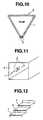
- the optical transmission tube 1is extended along the sides of a triangular emergency stop sign 9 which is used to inform the following drivers of the emergency stop of the car on the road.
- the linear illuminant element or system of the inventionmay find many other applications including (1) luminous nameplates, (2) guide poles used at night work, (3) luminous sticks, (4) luminous swords as sporting gears and toys, (5) warning lights suspended from tent ropes for warning against stumbling at night, (6) displays in aquariums, (7) course indicators and decorative lights in pools, (8) buoys, piers, banks and marine hoses (for providing improved visibility), (9) crossing gates, and (10) safety displays providing linear luminous bands for indicating crossing stop lines and the height limit of overhead beams or parking inlets.
Landscapes
- Physics & Mathematics (AREA)
- Engineering & Computer Science (AREA)
- Mechanical Engineering (AREA)
- General Physics & Mathematics (AREA)
- Optics & Photonics (AREA)
- Light Guides In General And Applications Therefor (AREA)
- Non-Portable Lighting Devices Or Systems Thereof (AREA)
- Extrusion Moulding Of Plastics Or The Like (AREA)
Description
- This invention relates to an optical transmission tubecomprising a tubular transparent cladding and a transparentcore having a higher index of refraction than the claddingand a method for preparing the same. Preferably, itrelates to an optical transmission tube allowing directionallight emergence from one side or outer surface area of thecladding, and to a linear illuminant systemhaving improved water resistance, improved environmentalresistance and a low power consumption for driving.
- Since optical transmission tubes comprising a tubularcladding and a core in the cladding having a higher index ofrefraction than the cladding are generally designed so as totransmit as much light as possible from one end to the otherend thereof, only a low luminance is generally availablenear the side surface of the tube. One possible measure forincreasing the luminance at the side surface of an opticaltransmission tube is by corrugating the cladding innersurface to scatter light. This measure is difficult toapply in that method for producing an optical transmissiontube which fills a tubular cladding with a core-formingpolymerizable monomer liquid and pressurises the liquid tocause the monomer to polymerize, because the claddingis likely to rupture.
- It may also be envisaged to disperse scatteringparticles in the core for increasing the luminance at theside surface of an optical transmission tube. It may occur to those skilled in the art to disperse scattering particlesin a monomer liquid and then polymerize and solidify themonomer. However, there has never been available a methodof adding scattering particles to a monomeric liquid andpolymerizing the liquid in a controlled manner such that thescattering particles are distributed in a limited area, thatis, so as to form a reflecting layer, at the end ofpolymerization.
- US 4,733,332 increases the luminance at the sidesurface of an optical transmission tube by adhering afine powder of high refractive index in a diffusionpattern to the outer surface of a light-transmitting rodwhich is surrounded with a transparent protection tube,with clearance between the rod and the tube.
- WO 98/20279, which is prior art by virtue of Article54(3) EPC, increase the luminance at the side surface ofan optical transmission tube by providing a lightdiffusible film, comprising a light-transmittable polymerand light diffusible reflective particles, on the outsideedge of a flexible light-transmitting rod.
- Known illuminant devices capable of providing linearlight emission over a length of several meters include neontubes and fluorescent tubes. Neon tubes and fluorescenttubes require high voltages, with the risk of-electricshocks and leakage. They cannot be used in water and atplaces where rain or snow reaches. Since the tubes areformed of glass, they cannot be used at places where failureof glass tubes by physical collision of people or vehiclesis expectable.
- Where the neon tubes and fluorescent tubes are used ina bent form, the glass tubes must be worked to the desiredcurvature, which requires skilled workers and hence, leadsto an increased cost. The power consumption of neon tubesand fluorescent tubes is as high as several tens of wattsper meter. For a long term of operation, they must beinstalled where a commercial power supply is available.
- To solve these problems, optical transmission tubes inthe form of a flexible tube filled with a transparent coreliquid or flexible transparent polymer and strands ofplastic optical fibers have been proposed. The systemincludes a light source and an optical transmission tubewhich receives light from the light source at one endthereof. The optical transmission tube is designed suchthat light may emerge from a side surface area of the tubeover a length of several tens of meters. Since the lightsource can be remote from the light emerging area, thissystem can be used in water, outdoor or even in anenvironment with the risk of explosion. The system is freeof the risk of breakage, eliminates complex cumbersome working such as glass working, and is readily applied at anecessary site.
- These optical transmission tubes provide lightemergence over a length of several tens of meters. Sincethe light emergent efficacy at the side surface is low, ahigh power light source of about 50 to 250 W is required inorder to provide an increased luminance. When such anoptical transmission tube is used in water, outdoor or in anenvironment with the risk of explosion for the purpose ofproviding side surface light emergence, a means forprotecting the light source is necessary. As a consequence,the light source is increased in size and its accommodationis significantly limited.
- An aim of the invention is to provide a new and usefuloptical transmission tube, and/or linear illuminant system.
- A preferred aim of the invention is to provide an opticaltransmission tube allowing directional emergence of lightfrom one side or an outer surface area thereof at a highluminance.
- Another preferred aim of the invention is to provide amethod for preparing the optical transmission tube.
- Another preferred aim of the invention is to provide alinear illuminant system which can be used in water, atplaces where rain or snow reaches, or in an environment withthe risk of explosion, which requires only a low power toproduce sufficient side light emergence, and which iscompact so that it may be installed at any desired place.
- In a first aspect, the invention provides a method of preparing an optical transmission tube (1),comprising the steps of:
- (a) dispersing scattering particles in a core-formingsolution comprising a monomer capable of forming a coreupon polymerization;
- (b) filling a tubular cladding (11) with the scatteringparticle-dispersed core-forming solution;
- (c) settling the scattering particles on an inner surfaceof the cladding by either (i) resting the tubular claddinghorizontally and allowing the scattering particles tosettle on a lower inner surface of the cladding, or (ii)centrifuging the cladding to settle the scatteringparticles; and
- (d) causing the core-forming solution to polymerize andsolidify within said cladding; thereby forming a solid core (12) within said cladding(11) and forming a reflecting layer (13) composed of thescattering particles in a strip form extending between saidcladding (11) and said core (12) and longitudinally of saidcladding (11).
- In a second aspect, the invention provides an opticaltransmission tube (1) obtainable by the method of the firstaspect of the invention.
- In the optical transmission tube of the invention, thereflecting layer in a strip form is disposed between thecladding and the core and extended longitudinally of thecladding. Intense light passing through the core providingthe maximum light quantity is reflected by the elongatedstrip-shaped reflecting layer and the reflected lightemerges from the tube through an area of the outer surfaceof the cladding opposed to the reflecting layer. (It isnoted that since the quantity of light passing through thecladding is small, the reflected light thereof is veryweak.) Intense light exits from the opposed outer surfacearea of the tube with a high directivity and at a high luminance, establishing a brightly illuminated state. Inthe place where the optical transmission tube is disposed,the elongated one side surface area of the tube is brightlyilluminant. In one embodiment wherein the reflecting layeris constructed of scattering particles such as siliconeresin particles, polystyrene resin particles or metal oxideparticles, the tube produces highly directional lightemergence having a high luminance. In another preferredembodiment, a metal sheet or a reflective coating havingscattering particles dispersed therein is formed on theouter surface of the cladding so as to surround thereflecting layer between the cladding and the core. Evenwhen the reflecting layer has defects such as pinholes,light leaking through the defects in the reflecting layer tothe rear side thereof and light laterally escaping outsidethe reflecting layer are reflected by the reflective coatingback to the opposed area. This further increases theluminance of light emergent from the opposed area (opposedto the reflecting layer) and significantly reduces the lossof light.
- The method of the invention may ensure that the strip-shapedreflecting layer is formed in a very simple manner.Then the optical transmission tube adapted to emit highlydirectional light at a high luminance from its one sidesurface area can be easily prepared.
- In a third aspect, the invention provides a linearilluminant system comprising an optical transmission tube of the second aspecta light source coupled to at least one endof the optical transmission tube in a water-proof manner, anda drive means for operating the light source.
- FIG. 1 is a fragmental axial cross-sectional view ofone exemplary optical transmission tube according to oneembodiment of the invention.
- FIG. 2 is a radial cross-sectional view of the opticaltransmission tube of FIG. 1.
- FIG. 3 is a radial cross-sectional view like FIG. 2,but showing an optical transmission tube according toanother embodiment.
- FIG. 4 schematically illustrates, partially in crosssection, a linear illuminant system according to theinvention.
- FIGS. 5 and 6 schematically illustrates opticaltransmission tubes according to further embodiments of theinvention.
- FIG. 7 is a radial cross-sectional view of an opticaltransmission tube with a reflective protective layer.
- FIGS. 8 and 9 are radial cross-sectional views ofoptical transmission tubes attached to different channels.
- FIG. 10 illustrates a sign to which the linearilluminant system of the invention is applied.
- FIG. 11 illustrates the linear illuminant system of theinvention as applied to a guide passage.
- FIG. 12 illustrates the linear illuminant system of theinvention as applied to a stairway.
- FIG. 13 illustrates the linear illuminant system of theinvention as applied to a panel.
- FIG. 14 illustrates the linear illuminant system of theinvention as applied to a segmented display board.
- FIG. 15 illustrates the linear illuminant system of theinvention as applied to a vehicle interior.
- FIG. 16 illustrates the linear illuminant system of theinvention as applied to a vehicle door.
- FIG. 17 illustrates the linear illuminant system of theinvention as applied to the vehicle rear side as sidelights.
- FIG. 18 illustrates the linear illuminant system of theinvention as applied to a stop sign attached to a vehicletrunk.
- Referring to FIGS. 1 and 2, an
optical transmissiontube 1 according to the invention is illustrated ascomprising a tubulartransparent cladding 11 having innerand outer surfaces and atransparent core 12 coaxiallydisposed within thecladding 11. Thecore 12 has a higherindex of refraction than thecladding 11. A reflectinglayer 13 in a strip form is disposed between thecladding 11and thecore 12. The strip form means that the reflectinglayer 13 extends longitudinally of thecladding 11 as viewedin the axial cross section of FIG. 1 and extends an arcuateas viewed in the radial cross section FIG. 2. That is, thereflectinglayer 13 extends only a part of a circle on oneside of the tube as viewed in the radial cross section ofFIG. 2. The reflectinglayer 13 may have a certainthickness extending from the core surface toward theinterior as shown in FIG. 2. With this construction, lightpassing through thecore 12 is reflected and scattered bythe reflectinglayer 13 and emerges from the tube through anarea of the outer surface of thecladding 11 that isapproximately diametrically opposed to the reflectinglayer 13, as shown by arrows L. Since the reflectinglayer 13 isdisposed at the one or bottom side in FIG. 2, the opposedarea from which the reflected light emerges is the other ortop side of the tube. - In one preferred embodiment, a reflective
protectivelayer 14 is disposed on the one side or bottom surface ofthecladding 11 so as to circumferentially andlongitudinally surround the reflectinglayer 13. - The tubular cladding is preferably constructed of flexible materials which are moldable into a tubular formand have a low index of refraction, such as plastics andelastomers. Illustrative examples of such flexiblematerials include polyethylene, polypropylene, polyamides,polystyrene, ABS resins, polymethyl methacrylate,polycarbonate, polyvinyl chloride, polyvinylidene chloride,polyvinyl acetate, polyethylene-vinyl acetate copolymers,polyvinyl alcohol, polyethylene-polyvinyl alcoholcopolymers, fluoro-resins, silicone resins, natural rubber,polyisoprene rubber, polybutadiene rubber, styrene-butadienecopolymers, butyl rubber, halogenated butyl rubber,chloroprene rubber, acrylic rubber, EPDM, acrylonitrile-butadienecopolymers, fluoro-rubber, and silicone rubber.
- Of these, silicone polymers and fluorinated polymershaving a low index of refraction are preferred. Exemplarysilicone polymers include polydimethylsiloxane polymers,polymethylphenylsiloxane polymers, and fluorosiliconepolymers; and exemplary fluorinated polymers includepolytetrafluoroethylene (PTFE), tetrafluoroethylenehexafluoropropylenecopolymers (FEP), tetrafluoroethyleneperfluoroalkoxyethylenecopolymers (PFE), polychlorotrifluoroethylene(PCTFE), ethylene-tetrafluoroethylenecopolymers (ETFE), polyvinylidene fluoride, polyvinylfluoride, vinylidene fluoride-trifluorochloroethylenecopolymers, vinylidene fluoride-hexafluoropropylenecopolymers, vinylidene fluoride-hexafluoropropylenetetrafluoroethyleneterpolymers, tetrafluoroethylenepropylenerubber, and fluorinated thermoplastic elastomers.The fluorinated polymers are especially preferred. Thesematerials may be used alone or in admixture of two or more.
- The core materials are preferably solid. Examplesinclude (meth)acrylic polymers, polycarbonate, ethylidenenorbornenepolymers, SBS, SIS, and SEBS (styrene-ethylenebutadiene-styreneblock polymers), with the (meth)acrylicpolymers being preferred.
- The (meth)acrylic polymers include homopolymersresulting from polymerization of a monomer selected fromacrylic acid, methacrylic acid, and esters thereof with monohydric alcohols, and copolymers resulting fromcopolymerization of two or more monomers. The monohydricalcohols are those having 1 to 22 carbon atoms. Inparticular, copolymers of a monomer selected from acrylicacid, methacrylic acid, and esters thereof with loweralcohols of 1 to 5 carbon atoms, preferably 1 to 3 carbonatoms, most preferably one carbon atom, with a monomer ofthe following general formula (1) are preferred because theyare well flexible or soft and light transmissive.

- In formula (1), R1 is a hydrogen atom or methyl group,and R2 is an alkyl group of 8 to 20 carbon atoms, preferably10 to 16 carbon atoms, more preferably 12 to 14 carbonatoms. The higher alkyl group represented by R2 may be asingle alkyl group or a mixture of alkyl groups, and mostpreferably a mixture of alkyl groups of 12 and 13 carbonatoms. The ratio of the alkyl group of 12 carbon atoms tothe alkyl group of 13 carbon atoms is preferably from 20:80to 80:20 by weight, and more preferably from 40:60 to 60:40by weight. The proportion of the monomer selected fromacrylic acid, methacrylic acid and lower alcohol estersthereof and the monomer of formula (1) to be copolymerizedis preferably from 5:95 to 79:21, and more preferably from30:70 to 65:35 in weight ratio.
- The diameter of the core is generally 2 to 30 mm,preferably 4 to 15 mm, though not critical.
- The reflecting layer is preferably constructed ofscattering particles, that is, particles capable ofscattering light. Exemplary scattering particles includeorganic polymer particles such as silicone resin particlesand polystyrene resin particles, metal oxide particles suchas Al2O3, TiO2 and SiO2, sulfate particles such as BaSO4, andcarbonate particles such as CaCO3, alone or in admixture oftwo or more.
- Preferably the scattering particles have a meanparticle size of 0.1 to 30 µm, especially 1 to 15 µm.Particles greater than 30 µm are sometimes disadvantageouswhen the optical transmission tube is prepared by theinventive method to be described later in detail becausesuch larger particles tend to settle out during the step ofintroducing the core-forming liquid into the tubularcladding.
- The thickness of the reflecting layer is preferably 10to 200 µm, especially 50 to 100 µm, though not critical. Atoo thin layer would reflect a less amount of light,resulting in a low luminance. A too thick layer wouldreflect a more amount of light to provide a high luminance,but over a short distance from the light source, sometimeswith the disadvantage of providing a lower luminance atpositions remote from the light source.
- When light leaks through defects in the reflectinglayer to the rear side thereof and light laterally escapesoutside the reflecting layer, the reflective protectivelayer serves to reflect such leakage light back to the otherside (or top side). The reflective protective layer may bea layer by which such leakage light is not transmitted, andpreferably a layer which reflects such leakage light withoutabsorbing it. Illustratively, the reflective protectivelayer may be a metal foil or sheet such as silver or aluminum, a reflective tape, a metallized tape, or a coatinghaving dispersed therein light-scattering particles asdescribed above.
- The
protective layer 14 on the outer surface of thecladding 11 may have a circumferential width sufficient tospan only the reflectinglayer 13 as shown in FIG. 2.Alternatively, as shown in FIG. 3, theprotective layer 14may have a greater circumferential width to extend beyondthe reflectinglayer 13 toward the other side (or top side)and to leave the lightemergent area 15 open. - The method for preparing the optical transmissiontube of the above-described construction according to theinvention involves the steps of dispersing scatteringparticles in a core-forming solution comprising a monomer ormonomers as described above, filling a tubular cladding withthe particle-dispersed core-forming solution, closing theopposite ends of the cladding with plugs, and resting thetubular cladding horizontally for about 1/2 to 48 hours forallowing the scattering particles to settle on a lower innersurface of the cladding. Instead of horizontal resting,centrifugation may be carried out. Thereafter, with theparticles kept settled, the monomer(s) is polymerized andcured within the cladding to thereby form a solid corewithin the cladding. A reflecting layercomposed of the scattering particles is thus formed in a stripform between the cladding and the core or in a shallowrecess in the surface of the core.
- In this method, the monomer polymerization technique isnot critical although the common technique is by adding apolymerization initiator to the monomer(s) and heating at 50to 120°C for 1 to 20 hours for effecting polymerization.Exemplary polymerization initiators include organicperoxides such as t-butyl hydroperoxide, di-t-butylperoxide, lauroyl peroxide, benzoyl peroxide, dimyristylperoxydicarbonate, t-butyl peroxyacetate, t-butyl peroxy(2-ethylhexanoate),and cumyl peroxyoctoate, and azo compoundssuch as asobisisobutyronitrile and azobiscyclohexanenitrile. It is recommended that the core-forming solution is polymerized while it is pressurized from one end or bothends of the clad tubing, so that no bubbles are generated inthe core.
- The optical transmission tube of the invention is toemit more light from its side surface area to provide a highluminance. The inventive method is effective for producingsuch an optical transmission tube.
- Next, the linear illuminant system according to theinvention is described.
- Referring to FIG. 4, a linear illuminant system isillustrated as comprising a
light transmission tube 1serving as a light emergent element, alight source 2coupled to one end of thelight transmission tube 1, and adrive means 3 for operating thelight source 2. The lighttransmission tube is constructed such that when lightemitted from the light source is transmitted by the light transmission tube, light emerges from a longitudinal side ofthe light transmission tube. - The
optical transmission tube 1 is constructed as shownin FIGS. 1 and 2, that is, includes a tubulartransparentcladding 11, atransparent core 12 having a higher index ofrefraction than thecladding 11, and a strip-shapedreflectinglayer 13 extending between thecladding 11 andthe core 12 on one side. Thetube 1 further includes areflectiveprotective layer 14 on the one side of thecladding 11 surrounding the reflectinglayer 13, which iseffective for increasing the reflection efficiency. Thedetail of the optical transmission tube is as describedabove. - The diameter and length of the core of the opticaltransmission tube are not critical. When a single LED isused as the
light source 2, for example, the core has adiameter of about 2 to 30 mm, preferably 4 to 15 mm and alength of about 0.1 to 5 m, preferably about 0.2 to 2 m. - The
light source 2 is coupled to at least onelongitudinal end (the left end in the illustratedembodiment) of theoptical transmission tube 1. It may be alight emitting diode (LED). Depending on the intendedapplication, a choice may be made among LEDs emitting lightof various colors such as red, blue, green, yellow, orangeand white. With respect to the number of LEDs used, asingle LED may be used, or plural LEDs may be used toincrease the light quantity. The LED may be coupled to oneend or both ends of the light tube. The embodiment whereinLEDs are coupled to both ends of the light tube providesmore uniform linear light emergence at a high luminance.With respect to the emission color of LEDs, they may emitmonochromatic light or a mixture of different colors. Inone exemplary application where the linear illuminant systemis installed at the stop line of a railroad crossing, thesystem having LEDs capable of emitting light of differentcolors may be designed such that the color of its lightemission may be changed, for example, yellow light isnormally emitted, but immediately before and during the passage of a train, red light is emitted to give warning topassersby. The LEDs may be continuously or intermittentlyoperated. - With respect to the attachment structure, one end ofthe
optical transmission tube 1 is fixedly secured to atubularjoint member 20 with an adhesive or by cramping.Thelight source 2 in the form of LED is received in thejoint member 20 and integrally coupled to the end face oftheoptical transmission tube 1. - The
light source 2 is electrically connected to thedrive means 3 by acord 30 with an insulating coat ofrubber, vinyl resin or polyethylene. To provide insulationaround the connection between thelight source 2 and thecord 30, thejoint member 20 is filled with apottingmaterial 21 such as an epoxy resin or silicone rubber forpreventing entry of water, water vapor, combustible gas orliquid. Thecord 30 may be inserted in a flexible sheath ofmetal or resin or a rubber or plastic pipe for protection orwater-proofness. - The structure of the optical transmission tube may bemodified. For example, as shown in FIG. 5, the
tube 1 maybe inserted into atransparent resin pipe 10A for protectionpurpose. As shown in FIG. 6, thetube 1 and thejointmember 20 may be enclosed with a transparent heatshrinkabletubing 10B which is heat shrunk into tight fit forprotecting thetube 1 and providing a seal over the entirestructure. - Further, as shown in FIG. 7, a light
reflective layer 14 may formed on a (one side) portion of the outer surfaceof theoptical transmission tube 1, for example, byattaching a reflective tape strip having a metal materialsuch as stainless steel, gold or silver evaporated,sputtered or plated thereon, applying a reflective coating,attaching a metal foil, applying reflecting particles suchas titanium oxide, or attaching a pigmented vinyl tape.Alternatively, a securingchannel opticaltransmission tube 1 as shown in FIGS. 8 and 9. If desired, thechannel channel - The drive means 3 for supplying electricity to the
light source 2 includes a power supply (e.g., a battery,solar battery or DC/AC power supply) and an electric circuit(including resistors, transistors, constant current diodes,etc., for example) for converting the power into directcurrent for operating the LED. The solar battery orsecondary battery may be incorporated in the drive means 3or externally connected to the drive means 3. A suitablesealant is applied where thecord 30 is extended from thedrive means 3, for providing water-proofness. - The lightsource is integrally coupled to the optical transmissiontube in a water-proof manner so that the opticaltransmission tube and the light source may be disposedoutdoor or in water, separately from the drive means. Thelinear illuminant system can be advantageously used inwater, at places where rain or snow reaches, or in anenvironment with the risk of explosion. The system requiresonly a low electric power to produce sufficient side lightemergence. The system is compact, and few restrictions areimposed on its installation site.
- Examples of the invention are given below by way ofillustration and not by way of limitation.
- A core-forming solution was prepared by mixing 60 partsby weight of methyl methacrylate (MMA), 40 parts by weightof lauryl methacrylate (LMA), and 0.05 part by weight ofbenzoyl peroxide (BPO) to form a monomer solution having aspecific gravity of 0.92. In 100 parts by weight of themonomer solution were dispersed 0.15 part by weight ofscattering particles which were silicone resin particleshaving a mean particle size of 7 µm and a specific gravityof 1.32 (commercially available from Toshiba K.K.) orpolystyrene resin particles having a mean particle size of10 µm and a specific gravity of 1.06 (commercially availablefrom Sekisui Chemicals K.K.). This solution was fed into aFEP tube having an outer diameter of 6 mm and a length of1.5 m, which was closed at both ends. The tube was restedon a horizontal table for 2 hours, allowing the particles tosettle on a lower inner surface of the FEP tube. The tubewas carefully transferred in a hot bath at 65°C so that theparticle deposit might remain intact. In the hot bath,while a pressure of 3.5 kg/cm2 was applied from the oppositeends of the tube, the monomer solution was polymerized andsolidified for 3 hours.
- There was obtained an optical transmission tube inwhich a reflecting layer composed of the scatteringparticles extended in a strip form on the core surface andlongitudinally of the tube.
- The optical transmission tube was tested by coupling ahalogen lamp of 20 W as the light source with the tube sothat light entered the tube from one end face. Lightemerged from the tube along an elongated area of the otherside surface of the tube opposed to the reflecting layer.The luminance of light was measured on the other side of thetube, using a colorimeter CS100 (Minolta K.K.). Measurementwas made along the length of the tube at distances of 10 cm, 20 cm, 30 cm and 40 cm from the light incident end face ofthe tube. The results are shown in Table 1.
- For comparison purposes, an optical transmission tubewas similarly prepared by filling the FEP tube with themonomer solution free of the particles and polymerizing themonomer solution. The tube was similarly measured for sideluminance. The results are shown in Table 1.
Dispersed particles Side luminance (cd/m2) at a distance from the incident end Type Amount (pbw) 10 cm 20 cm 30 cm 40 cm Comparative Example - 0 65 19 12 11 Example Polystyrene particles 0.15 620 410 310 205 Silicone particles 0.15 613 422 380 265 - It is evident from Table 1 that as compared with thecomparative tube without a reflecting layer, the tubeshaving a reflecting layer formed therein as a result ofaddition of scattering particles to a monomer solution allowlight to emerge from the side surface at a higher luminance.In the inventive tubes, the luminance is kept high even atdistances remote from the light source, that is, theluminance distribution has a gentle slope.
- The optical transmission tube prepared as in Example 1was measured for side luminance using a red LED lamp lightsource (applied voltage 2V, current 20 mA, 0.04 W). Theresults are shown in Table 2.
- A reflective tape (adhesive tape) of vinyl chlorideresin loaded with a white pigment was attached to the oneside surface of the cladding of the tube to surround thereflecting layer. This tube was also measured for sideluminance, with the results shown in Table 2.
Dispersed particles Side luminance (cd/m2) at a distance from the incident end Type Amount (pbw) 5 cm 12 cm 20 cm Comparative Example - 0 3.3 1.0 0.4 Example Silicone particles 0.5 10.2 10.0 9.6 Silicone particles+ reflective tape 0.5 16.8 16.5 16 - It is evident from Table 2 that the tubes within thescope of the invention provide a high side luminance and theattachment of reflective tape improves the luminance. Ascompared with the tubes of Example 1 using the halogen lampof 20 W, the tubes of this Example produce a lower overallluminance level since the LED used therein is operated witha power of 0.04 w.
- The optical transmission tube used herein was the tubeof 30 cm long having a reflecting layer of silicone resinparticles obtained in Example 1. A mirror finishedstainless steel disc having a thickness of 1 mm and adiameter of 6 mm was joined to one end face of the tube witha clear epoxy adhesive as a reflecting plate. A green lightemitting LED NSPG50 (by Nichia Chemical K.K.) was coupled tothe other end face of the tube using an aluminum joint.Lead conductors were soldered to terminals of the LED whilethe connection zone was covered with a silicone rubberadhesive to provide a water-proof seal. A linear illuminantelement (Example 3A) was constructed in this way.
- A comparative linear illuminant element was similarlyconstructed using the tube of Comparative Example in Example1.
- A current flow of 20 mA was conducted from a powersupply to the LED whereby light emerged from the side areaof the tube. The tube was measured for side luminance as inExample 1. Measurement was made along the length of thetube at distances of 50 mm, 150 mm, and 250 mm from thelight incident end face of the tube. The results are shownin Table 5. The element of Example 3A produced a higherluminance than the comparative element. The powerconsumption was 0.06 W.
- The linear illuminant element was immersed in water for6 months. Even after water immersion, the element could beoperated to provide the same light emission as the initialelement without current leakage and other problems.
- A linear illuminant element (Example 3B) was similarlyconstructed except that a channel as shown at 15 or 16 inFIG. 8 or 9 was formed from a highly reflective resin Banlite LD-1000R (Teijin K.K.) and the optical transmissiontube was fitted into the channel. The channel itself wasreflective. The tube was measured for side luminance as inExample 1, with the results shown in Table 5.
Side luminance (cd/m2) at a distance from the incident end 50 mm 150 mm 250 mm Example 3A 120 100 100 Example 3B 200 180 175 Comparative Example 20 10 10 - As is evident from Table 5, the tube of Example 3Bhaving the reflective
protective layer 14 in the form of achannel produced the highest side luminance, the tube ofExample 3A having the reflectinglayer 13 produced a highside luminance, and the tube of Comparative Example withoutthe reflectinglayer 13 and the reflectiveprotective layer 14 produced the lowest side luminance. - Referring to FIGS. 10 to 18, the application of thelinear illuminant element or system is described.
- In FIG. 10, the
optical transmission tube 1 of thelinear illuminant system is extended along the peripheralsides of asign board 4. The sign board with such anilluminant molding contributes to safety driving at night. - In FIG. 11, the
optical transmission tubes 1 areattached to aside wall 5 of a tunnel. Equivalent objectsinclude underground passages, corridors in buildings andhospitals, and emergency paths in public facilities such astheaters and halls. In this application, a commercial powersupply may be used as the drive means for the light source.A provision is made such that upon a power failure, thelight source can be driven by a battery. As opposed toincandescent lamps and fluorescent lamps which can be burnedwith batteries for a time as short as several ten minutes,the LED used as the light source is expected to provide afar longer time of operation even when operated by a battery. The linearity of light emission instructs a safesmooth guide to people because the guidance path isascertainable by an instant look. - In FIG. 12, the
optical transmission tubes 1 areextended along the upper edges of upright walls 6 of astairway for preventing an accident by misstep at night.When the tubes are attached to an emergency stairway, thestairway can be readily ascertained upon emergency at night,contributing to safe evacuation guidance. - In FIG. 13, the
optical transmission tubes 1 areextended along the peripheral sides of anadvertising board 7. FIG. 14 shows a segmented display panel 4' forindicating the maximum speed. For each digit, seven tubesare combined such that selected ones may be operated whilethe remaining ones are extinct. This enables variableindication of the speed limit. By increasing the number ofsegments, a character or modified display is possible. - The invention is also applicable to automobiles. InFIG. 15, the
optical transmission tube 1 is extended alongthe side of avehicle interior 8A for providing indirectillumination. In FIG. 16, theoptical transmission tube 1is attached to a lower portion of the inner wall of adoor 8B, serving as a foot light. In FIG. 17, theopticaltransmission tubes 1 are attached to the rear side 8C of avehicle, serving as side lights. In FIG. 18, theopticaltransmission tube 1 is extended along the sides of atriangular emergency stop sign 9 which is used to inform thefollowing drivers of the emergency stop of the car on theroad. - In addition to the foregoing examples, the linearilluminant element or system of the invention may find manyother applications including (1) luminous nameplates, (2)guide poles used at night work, (3) luminous sticks, (4)luminous swords as sporting gears and toys, (5) warninglights suspended from tent ropes for warning againststumbling at night, (6) displays in aquariums, (7) courseindicators and decorative lights in pools, (8) buoys, piers,banks and marine hoses (for providing improved visibility), (9) crossing gates, and (10) safety displays providinglinear luminous bands for indicating crossing stop lines andthe height limit of overhead beams or parking inlets.
- Although some preferred embodiments have beendescribed, many modifications and variations may be madethereto in light of the above teachings. It is therefore tobe understood that the invention may be practiced otherwisethan as specifically described without departing from thescope of the appended claims.

Claims (7)
- A method of preparing an optical transmission tube(1), comprising the steps of:thereby forming a solid core (12) within said cladding(11) and forming a reflecting layer (13) composed of thescattering particles in a strip form extending between saidcladding (11) and said core (12) and longitudinally of saidcladding (11).(a) dispersing scattering particles in a core-formingsolution comprising a monomer capable of forming a coreupon polymerization;(b) filling a tubular cladding (11) with the scatteringparticle-dispersed core-forming solution;(c) settling the scattering particles on an inner surfaceof the cladding by either (i) resting the tubular claddinghorizontally and allowing the scattering particles tosettle on a lower inner surface of the cladding, or (ii)centrifuging the cladding to settle the scatteringparticles; and(d) causing the core-forming solution to polymerize andsolidify within said cladding;
- A method according to claim 1 further comprising thestep of:(e) forming a reflective protective layer (14) on an areaof the outer surface of said cladding (11) surrounding thereflecting layer (13).
- A method according to claim 1 or claim 2 wherein saidcladding (11) is constructed of a silicone or fluorinatedpolymer.
- A method according to claim 3 wherein said cladding(11) is constructed of a fluorinated polymer.
- A method according to any one of the preceding claimswherein said core (12) is constructed of an acrylicpolymer.
- An optical transmission tube (1) obtainable by themethod of any one of claims 1 to 5.
- A linear illuminant system comprising:an optical transmission tube (1) according to claim 6;a light source (2) coupled to at least one end of saidoptical transmission tube (1) in a water-proof manner; anda drive means (3) for operating the light source (2).
Priority Applications (1)
| Application Number | Priority Date | Filing Date | Title |
|---|---|---|---|
| EP02005409AEP1221628B1 (en) | 1997-04-24 | 1998-04-24 | Optical transmission tube, method for making it and linear illuminant system |
Applications Claiming Priority (6)
| Application Number | Priority Date | Filing Date | Title |
|---|---|---|---|
| JP121676/97 | 1997-04-24 | ||
| JP12167697 | 1997-04-24 | ||
| JP12167697 | 1997-04-24 | ||
| JP241892/97 | 1997-08-22 | ||
| JP24189297 | 1997-08-22 | ||
| JP9241892AJPH1166928A (en) | 1997-08-22 | 1997-08-22 | Linear luminous body |
Related Child Applications (1)
| Application Number | Title | Priority Date | Filing Date |
|---|---|---|---|
| EP02005409ADivisionEP1221628B1 (en) | 1997-04-24 | 1998-04-24 | Optical transmission tube, method for making it and linear illuminant system |
Publications (3)
| Publication Number | Publication Date |
|---|---|
| EP0874191A2 EP0874191A2 (en) | 1998-10-28 |
| EP0874191A3 EP0874191A3 (en) | 1999-01-07 |
| EP0874191B1true EP0874191B1 (en) | 2002-09-04 |
Family
ID=26458973
Family Applications (2)
| Application Number | Title | Priority Date | Filing Date |
|---|---|---|---|
| EP98303168AExpired - LifetimeEP0874191B1 (en) | 1997-04-24 | 1998-04-24 | Optical transmission tube, method for making it and linear illuminant system |
| EP02005409AExpired - LifetimeEP1221628B1 (en) | 1997-04-24 | 1998-04-24 | Optical transmission tube, method for making it and linear illuminant system |
Family Applications After (1)
| Application Number | Title | Priority Date | Filing Date |
|---|---|---|---|
| EP02005409AExpired - LifetimeEP1221628B1 (en) | 1997-04-24 | 1998-04-24 | Optical transmission tube, method for making it and linear illuminant system |
Country Status (3)
| Country | Link |
|---|---|
| US (1) | US5982969A (en) |
| EP (2) | EP0874191B1 (en) |
| DE (2) | DE69807564T2 (en) |
Families Citing this family (165)
| Publication number | Priority date | Publication date | Assignee | Title |
|---|---|---|---|---|
| DE10347053A1 (en)* | 2003-10-07 | 2005-05-04 | Hella Kgaa Hueck & Co | Interior light for vehicles |
| US6185356B1 (en)* | 1995-06-27 | 2001-02-06 | Lumitex, Inc. | Protective cover for a lighting device |
| US7306559B2 (en)* | 1997-07-02 | 2007-12-11 | Lumitex, Inc. | Illuminated surgical retractor |
| US6591049B2 (en) | 1997-07-02 | 2003-07-08 | Lumitex, Inc. | Light delivery systems and applications thereof |
| US20050171408A1 (en)* | 1997-07-02 | 2005-08-04 | Parker Jeffery R. | Light delivery systems and applications thereof |
| US6739744B2 (en)* | 1997-07-02 | 2004-05-25 | Lumitex, Inc. | Light delivery systems and applications thereof |
| US6806659B1 (en) | 1997-08-26 | 2004-10-19 | Color Kinetics, Incorporated | Multicolored LED lighting method and apparatus |
| US20030133292A1 (en) | 1999-11-18 | 2003-07-17 | Mueller George G. | Methods and apparatus for generating and modulating white light illumination conditions |
| US6720745B2 (en) | 1997-08-26 | 2004-04-13 | Color Kinetics, Incorporated | Data delivery track |
| US7161313B2 (en)* | 1997-08-26 | 2007-01-09 | Color Kinetics Incorporated | Light emitting diode based products |
| US7352339B2 (en) | 1997-08-26 | 2008-04-01 | Philips Solid-State Lighting Solutions | Diffuse illumination systems and methods |
| US7014336B1 (en) | 1999-11-18 | 2006-03-21 | Color Kinetics Incorporated | Systems and methods for generating and modulating illumination conditions |
| US7038398B1 (en) | 1997-08-26 | 2006-05-02 | Color Kinetics, Incorporated | Kinetic illumination system and methods |
| US6863428B2 (en)* | 1997-10-24 | 2005-03-08 | 3M Innovative Properties Company | Light guide illumination device appearing uniform in brightness along its length |
| US7598686B2 (en) | 1997-12-17 | 2009-10-06 | Philips Solid-State Lighting Solutions, Inc. | Organic light emitting diode methods and apparatus |
| GB2336660B (en)* | 1998-04-20 | 2002-03-06 | Bridgestone Corp | Light transmission tubes and methods for manufacturing the light transmission tubes |
| JPH11326644A (en)* | 1998-05-20 | 1999-11-26 | Bridgestone Corp | Light transmission tube and its production |
| GB9820854D0 (en)* | 1998-09-24 | 1998-11-18 | Lifor Limited | Fibre optic based directional way finding apparatus and method |
| US6519401B1 (en) | 1998-10-28 | 2003-02-11 | 3M Innovative Properties Company | Light fibers and methods for producing the same |
| US6236797B1 (en)* | 1998-11-05 | 2001-05-22 | Bridgestone Corporation | Light transmitting tube |
| AU3209600A (en)* | 1999-01-14 | 2000-08-01 | Federal Mogul Corporation | Waveguide assembly for laterally-directed illumination in a vehicle lighting system |
| US6152586A (en)* | 1999-01-28 | 2000-11-28 | Transmatic, Inc. | Cargo area lighting system for trucks |
| WO2000045203A1 (en)* | 1999-01-28 | 2000-08-03 | Bridgestone Corporation | Linear luminous body and production method thereof and scanner |
| US6398778B1 (en) | 1999-06-18 | 2002-06-04 | Photonics Research Ontario | Optical fiber diffuser |
| CA2375267A1 (en)* | 1999-06-18 | 2000-12-28 | Xijia Gu | Optical fiber diffuser |
| WO2001005627A1 (en)* | 1999-07-16 | 2001-01-25 | Bridgestone Corporation | Lighting apparatus and meter case for vehicle |
| DE19940849B4 (en)* | 1999-08-27 | 2013-01-03 | Lisa Dräxlmaier GmbH | optical fiber |
| US6577794B1 (en)* | 1999-09-27 | 2003-06-10 | Robert M. Currie | Compound optical and electrical conductors, and connectors therefor |
| US20020176259A1 (en) | 1999-11-18 | 2002-11-28 | Ducharme Alfred D. | Systems and methods for converting illumination |
| EP1264298B1 (en) | 2000-03-06 | 2007-01-03 | Teledyne Lighting and Display Products, Inc. | Led light source with field-of-view-controlling optics |
| EP1264353A2 (en) | 2000-03-06 | 2002-12-11 | Teledyne Lighting and Display Products, Inc. | Lighting apparatus having quantum dot layer |
| US6501218B1 (en)* | 2000-06-12 | 2002-12-31 | General Electric Company | Outdoor electroluminescent display devices |
| US7202613B2 (en) | 2001-05-30 | 2007-04-10 | Color Kinetics Incorporated | Controlled lighting methods and apparatus |
| US6450677B1 (en) | 2000-09-21 | 2002-09-17 | Robert M. Knauer | Fiberoptic lighting system |
| US6637924B2 (en) | 2000-11-15 | 2003-10-28 | Teledyne Lighting And Display Products, Inc. | Strip lighting apparatus and method |
| US6634779B2 (en)* | 2001-01-09 | 2003-10-21 | Rpm Optoelectronics, Inc. | Method and apparatus for linear led lighting |
| US20020159741A1 (en)* | 2001-02-26 | 2002-10-31 | Graves Stephen M. | Optical transmission tube and applications thereof |
| AU2002308415B2 (en)* | 2001-05-22 | 2006-03-02 | Poly Optics Australia Pty Ltd | Side scattering polymer light guide and method of manufacture |
| AUPR518801A0 (en)* | 2001-05-22 | 2001-06-14 | Poly Optics Australia Pty Ltd | Side scattering fibre-optic and method of manufacturing a side scattering fibre-optic |
| US6784603B2 (en)* | 2001-07-20 | 2004-08-31 | Teledyne Lighting And Display Products, Inc. | Fluorescent lighting apparatus |
| US8388164B2 (en)* | 2005-05-17 | 2013-03-05 | Michael Waters | Hands-Free lighting devices |
| US6769799B2 (en)* | 2002-03-12 | 2004-08-03 | Tyco Electronics Canada | Apparatus, methods and articles of manufacture for a co-extruded light pipe |
| GB0211351D0 (en)* | 2002-05-16 | 2002-06-26 | Lasota Andrew S | Illuminable display device |
| AU2002951256A0 (en)* | 2002-09-06 | 2002-09-19 | Poly Optics Australia Pty Ltd | Improvements in side-scattering light guides |
| JP3753117B2 (en)* | 2002-09-17 | 2006-03-08 | ヤマハ株式会社 | Electronic device and method of mounting the display device |
| US7300192B2 (en) | 2002-10-03 | 2007-11-27 | Color Kinetics Incorporated | Methods and apparatus for illuminating environments |
| EP1558951A1 (en)* | 2002-10-21 | 2005-08-03 | Plastic Inventions and Patents, Inc. | Compound optical and electrical conductors, and connectors therefor |
| US6834988B2 (en)* | 2002-11-05 | 2004-12-28 | General Binding Corporation | Enhanced thermal indicator light system and method for the use thereof |
| WO2004070262A2 (en)* | 2003-02-04 | 2004-08-19 | Ilight Technologies, Inc. | Flexible illumination device for simulating neon lighting |
| US7194184B2 (en)* | 2003-03-10 | 2007-03-20 | Fiberstars Incorporated | Light pipe with side-light extraction |
| US7164819B2 (en)* | 2003-03-10 | 2007-01-16 | Fiberstars, Inc. | Side-light extraction by light pipe-surface alteration and light-extraction devices extending radially beyond the outer cladding |
| US6910795B2 (en)* | 2003-04-18 | 2005-06-28 | Tyco Electronics Canada, Ltd. | Overmolded low voltage lamp assembly |
| US20070110378A1 (en)* | 2003-08-04 | 2007-05-17 | Zarian James R | Light-emitting form exhibiting an aura |
| US20050068790A1 (en)* | 2003-09-25 | 2005-03-31 | Love David A. | Light emitting diode glow tube |
| US20050084229A1 (en)* | 2003-10-20 | 2005-04-21 | Victor Babbitt | Light insertion and dispersion system |
| US20050094415A1 (en)* | 2003-10-29 | 2005-05-05 | Bor-Dong Cheng | Body molding for car |
| IL158952A0 (en)* | 2003-11-19 | 2004-05-12 | Elam Electroluminescent Ind Lt | Electroluminescent flexible modular light source |
| GB0329205D0 (en)* | 2003-12-17 | 2004-01-21 | Graham Morton | An illumination device |
| US20050157128A1 (en)* | 2004-01-21 | 2005-07-21 | Silverbrook Research Pty Ltd | Pagewidth inkjet printer cartridge with end electrical connectors |
| US7083273B2 (en)* | 2004-01-21 | 2006-08-01 | Silverbrook Research Pty Ltd | Inkjet printer cartridge with uniform compressed air distribution |
| US7731327B2 (en) | 2004-01-21 | 2010-06-08 | Silverbrook Research Pty Ltd | Desktop printer with cartridge incorporating printhead integrated circuit |
| US7360868B2 (en)* | 2004-01-21 | 2008-04-22 | Silverbrook Research Pty Ltd | Inkjet printer cartridge with infrared ink delivery capabilities |
| US7367647B2 (en)* | 2004-01-21 | 2008-05-06 | Silverbrook Research Pty Ltd | Pagewidth inkjet printer cartridge with ink delivery member |
| US7328985B2 (en)* | 2004-01-21 | 2008-02-12 | Silverbrook Research Pty Ltd | Inkjet printer cartridge refill dispenser with security mechanism |
| US7448734B2 (en)* | 2004-01-21 | 2008-11-11 | Silverbrook Research Pty Ltd | Inkjet printer cartridge with pagewidth printhead |
| US7303255B2 (en) | 2004-01-21 | 2007-12-04 | Silverbrook Research Pty Ltd | Inkjet printer cartridge with a compressed air port |
| US20050157125A1 (en)* | 2004-01-21 | 2005-07-21 | Silverbrook Research Pty Ltd | Inkjet printer cartridge with integral shield |
| US7441865B2 (en) | 2004-01-21 | 2008-10-28 | Silverbrook Research Pty Ltd | Printhead chip having longitudinal ink supply channels |
| US7524016B2 (en)* | 2004-01-21 | 2009-04-28 | Silverbrook Research Pty Ltd | Cartridge unit having negatively pressurized ink storage |
| US7469989B2 (en)* | 2004-01-21 | 2008-12-30 | Silverbrook Research Pty Ltd | Printhead chip having longitudinal ink supply channels interrupted by transverse bridges |
| US7287846B2 (en)* | 2004-01-21 | 2007-10-30 | Silverbrook Research Pty Ltd | Inkjet printer cartridge with combined blotter |
| US7645025B2 (en) | 2004-01-21 | 2010-01-12 | Silverbrook Research Pty Ltd | Inkjet printer cartridge with two printhead integrated circuits |
| US20050157000A1 (en)* | 2004-01-21 | 2005-07-21 | Silverbrook Research Pty Ltd | Inkjet printer cradle with end data and power contacts |
| US20050157112A1 (en)* | 2004-01-21 | 2005-07-21 | Silverbrook Research Pty Ltd | Inkjet printer cradle with shaped recess for receiving a printer cartridge |
| US7364264B2 (en)* | 2004-01-21 | 2008-04-29 | Silverbrook Research Pty Ltd | Inkjet printer cradle with single drive motor performing multiple functions |
| US7198352B2 (en)* | 2004-01-21 | 2007-04-03 | Kia Silverbrook | Inkjet printer cradle with cartridge stabilizing mechanism |
| US7097291B2 (en) | 2004-01-21 | 2006-08-29 | Silverbrook Research Pty Ltd | Inkjet printer cartridge with ink refill port having multiple ink couplings |
| US7374355B2 (en) | 2004-01-21 | 2008-05-20 | Silverbrook Research Pty Ltd | Inkjet printer cradle for receiving a pagewidth printhead cartridge |
| DE202004021432U1 (en)* | 2004-03-29 | 2008-02-21 | Albis Plastic Gmbh | Illuminable information unit |
| EP1735563A4 (en)* | 2004-04-16 | 2007-11-28 | Fiberstars Inc | Efficient luminaire with directional side-light extraction |
| US20050244610A1 (en)* | 2004-04-29 | 2005-11-03 | Visteon Global Technologies, Inc. | Injection molding of components for vehicles |
| US7273300B2 (en)* | 2004-08-06 | 2007-09-25 | Lumination Llc | Curvilinear LED light source |
| US20060044824A1 (en)* | 2004-08-24 | 2006-03-02 | Yung-Hwa Chen | Soft warning strip |
| CA2579196C (en)* | 2004-09-10 | 2010-06-22 | Color Kinetics Incorporated | Lighting zone control methods and apparatus |
| US7389020B2 (en)* | 2005-01-28 | 2008-06-17 | Intier Automotive Inc. | Light pipe assembly |
| US7549783B2 (en)* | 2005-04-18 | 2009-06-23 | Energy Focus, Inc. | Efficient luminaire with directional side-light extraction |
| US9526292B2 (en) | 2005-05-17 | 2016-12-27 | Michael Waters | Power modules and headgear |
| JP2007022325A (en)* | 2005-07-15 | 2007-02-01 | Fujikura Ltd | Lighting device for vehicle door |
| US8409088B2 (en) | 2006-01-18 | 2013-04-02 | Invuity, Inc. | Retractor illumination system |
| US7374313B2 (en)* | 2006-03-02 | 2008-05-20 | Energy Focus, Inc. | Luminaire with improved lateral illuminance control |
| EP1833035B1 (en)* | 2006-03-08 | 2009-06-24 | C.R.F. Societa Consortile per Azioni | Modular system for luminous signals |
| US7588342B2 (en)* | 2006-04-24 | 2009-09-15 | Energy Focus, Inc. | Lighted refrigerated display case with remote light source |
| US8047987B2 (en) | 2006-05-26 | 2011-11-01 | Invuity, Inc. | Blade insert illuminator |
| DE102006035521B4 (en)* | 2006-07-31 | 2014-09-04 | Audi Ag | motor vehicle |
| GB0625761D0 (en)* | 2006-12-22 | 2007-02-07 | Graham Morton | A lighting device |
| US20090027914A1 (en)* | 2007-07-26 | 2009-01-29 | Chia-Yeh Wu | Structure for a center high mounted stop lamp |
| JP5443677B2 (en)* | 2007-09-21 | 2014-03-19 | オリンパスメディカルシステムズ株式会社 | Illumination device and endoscope |
| US8088066B2 (en) | 2007-10-24 | 2012-01-03 | Invuity, Inc. | Blade insert illuminator |
| WO2009074510A1 (en) | 2007-12-10 | 2009-06-18 | Volkswagen Ag | Vehicle lamp and method for producing a transparent element for a vehicle lamp |
| US8491145B2 (en) | 2007-12-18 | 2013-07-23 | Waters Industries, Inc. | Illuminated headgear having switch devices and packaging therefor |
| US8757831B2 (en) | 2007-12-18 | 2014-06-24 | Michael Waters | Headgear having an electrical device and power source mounted thereto |
| BRPI0819557A2 (en) | 2007-12-18 | 2015-05-05 | Michael Waters | "Light head accessory, camera and light head accessory combination, flap sleeve, packaging assembly and head accessory" |
| EP2242973A1 (en)* | 2008-01-02 | 2010-10-27 | Illinois Tool Works Inc. | Lighting device for a refrigerating storing device and refrigerating storing device comprising such lighting device |
| JP5480822B2 (en)* | 2008-02-14 | 2014-04-23 | ショット アクチエンゲゼルシャフト | Side radiating step index fiber |
| US11382711B2 (en) | 2008-08-13 | 2022-07-12 | Invuity, Inc. | Cyclo olefin polymer and copolymer medical devices |
| CA2753717C (en) | 2009-02-27 | 2016-07-12 | Michael Waters | Lighted hat |
| US8998472B2 (en)* | 2009-05-04 | 2015-04-07 | Walter A Johanson | Liquid filled light guide containing voids within the walls |
| US9800017B1 (en) | 2009-05-29 | 2017-10-24 | Soraa Laser Diode, Inc. | Laser device and method for a vehicle |
| US10108079B2 (en) | 2009-05-29 | 2018-10-23 | Soraa Laser Diode, Inc. | Laser light source for a vehicle |
| US8218938B2 (en)* | 2009-07-02 | 2012-07-10 | Chang-Hsien Ho | Light guide strip structure |
| US20110090710A1 (en)* | 2009-10-15 | 2011-04-21 | Edmund Joseph Kelly | High Efficiency Light Pipe |
| JP6052779B2 (en) | 2009-11-20 | 2016-12-27 | コーニング インコーポレイテッド | Illumination system with side-emitting photonic optical fiber and method for manufacturing the same |
| CN202975580U (en) | 2010-04-30 | 2013-06-05 | 迈克尔·沃特斯 | Headgear and hat-mounted camera rig |
| US8540409B2 (en)* | 2010-05-27 | 2013-09-24 | Osram Opto Semiconductors Gmbh | Light guide and semiconductor luminaire |
| DE102010025350A1 (en)* | 2010-06-28 | 2011-11-03 | Audi Ag | Lighting device, particularly for motor vehicle, has light source, light conductor, light uncoupling surface and light uncoupling element for turning light in direction of light uncoupling surface |
| JP5561153B2 (en)* | 2010-12-27 | 2014-07-30 | ティアック株式会社 | Electronic device and light guide lens mounting method |
| CA2794370A1 (en) | 2011-11-04 | 2013-05-04 | Michael Waters | Hat with automated shut-off feature for electrical devices |
| EP2788291A1 (en)* | 2011-12-09 | 2014-10-15 | MAG Aerospace Industries, LLC | Inline uv led water disinfection and heating |
| US9568173B2 (en) | 2011-12-23 | 2017-02-14 | Michael Waters | Lighted hat |
| US9526287B2 (en) | 2011-12-23 | 2016-12-27 | Michael Waters | Lighted hat |
| US9609902B2 (en) | 2011-12-23 | 2017-04-04 | Michael Waters | Headgear having a camera device |
| US8620123B2 (en) | 2012-02-13 | 2013-12-31 | Corning Cable Systems Llc | Visual tracer system for fiber optic cable |
| DE102012019074A1 (en)* | 2012-09-27 | 2014-03-27 | Airbus Operations Gmbh | Mobile lighting system |
| WO2014100477A1 (en) | 2012-12-19 | 2014-06-26 | Michael Waters | Lighted solar hat |
| US20140218955A1 (en)* | 2013-02-01 | 2014-08-07 | Scott Lee | Illuminated moldings with integrated control |
| US9254785B2 (en)* | 2013-02-14 | 2016-02-09 | Ford Global Technologies, Llc | Extruded light pipe carrier |
| GB2511139B (en)* | 2013-02-26 | 2015-01-14 | Visteon Global Tech Inc | Strip lighting device |
| WO2014144507A1 (en) | 2013-03-15 | 2014-09-18 | Michael Waters | Lighted headgear |
| WO2014186589A1 (en)* | 2013-05-15 | 2014-11-20 | Johnson Controls Technology Company | Vehicle interior component having an illuminated pinstripe |
| US20140363134A1 (en)* | 2013-06-10 | 2014-12-11 | Corning Optical Communications LLC | Optical fiber cable assembly comprising optical tracer fiber |
| US9429731B2 (en)* | 2013-08-12 | 2016-08-30 | Corning Optical Communications LLC | Optical fiber cable assembly comprising optical tracer fiber |
| US9643350B2 (en) | 2013-09-11 | 2017-05-09 | Ford Global Technologies, Llc | Wet-out prevent method using laminate for injection molding process |
| TW201525044A (en)* | 2013-12-16 | 2015-07-01 | Genesis Photonics Inc | Light-emitting device and wavelength conversion layer manufacturing method |
| JP6287421B2 (en) | 2014-03-24 | 2018-03-07 | 株式会社デンソー | Light guide member, attachment for light guide member, illumination device |
| JP6303728B2 (en)* | 2014-03-31 | 2018-04-04 | 東芝ライテック株式会社 | lamp |
| USD770143S1 (en) | 2014-05-23 | 2016-11-01 | Michael Waters | Beanie with means for illumination |
| US20170176663A1 (en)* | 2014-06-06 | 2017-06-22 | Keiwa Inc. | Edge-lit backlight unit and reflective tape member |
| US10379309B2 (en) | 2014-11-18 | 2019-08-13 | Corning Optical Communications LLC | Traceable optical fiber cable and filtered viewing device for enhanced traceability |
| US10228526B2 (en) | 2015-03-31 | 2019-03-12 | Corning Optical Communications LLC | Traceable cable with side-emitting optical fiber and method of forming the same |
| US10101553B2 (en) | 2015-05-20 | 2018-10-16 | Corning Optical Communications LLC | Traceable cable with side-emitting optical fiber and method of forming the same |
| EP3325876A1 (en) | 2015-07-17 | 2018-05-30 | Corning Optical Communications LLC | Systems and methods for traceable cables |
| EP3326014A1 (en) | 2015-07-17 | 2018-05-30 | Corning Optical Communications LLC | Systems and methods for tracing cables and cables for such systems and methods |
| US11437774B2 (en) | 2015-08-19 | 2022-09-06 | Kyocera Sld Laser, Inc. | High-luminous flux laser-based white light source |
| US10938182B2 (en) | 2015-08-19 | 2021-03-02 | Soraa Laser Diode, Inc. | Specialized integrated light source using a laser diode |
| US10101545B2 (en) | 2015-10-30 | 2018-10-16 | Corning Optical Communications LLC | Traceable cable assembly and connector |
| US9986438B2 (en) | 2016-01-22 | 2018-05-29 | Microsoft Technology Licensing, Llc | Hierarchical spectrum coordination |
| CN109154701A (en) | 2016-04-08 | 2019-01-04 | 康宁研究与开发公司 | With light structures and for carrying the traceable fiber optical cable assembly from the tracking optical fiber of the received light of light originating device |
| US10107983B2 (en) | 2016-04-29 | 2018-10-23 | Corning Optical Communications LLC | Preferential mode coupling for enhanced traceable patch cord performance |
| US10222560B2 (en) | 2016-12-21 | 2019-03-05 | Corning Research & Development Corporation | Traceable fiber optic cable assembly with fiber guide and tracing optical fibers for carrying light received from a light launch device |
| FR3061562B1 (en)* | 2017-01-04 | 2019-08-02 | Valeo Vision | REMOVABLE CONNECTION DEVICE FOR A LIGHT GUIDE AND APPLICATION IN A MOTOR VEHICLE, OPTICAL TRANSMISSION MODULE PROVIDED WITH THE DEVICE |
| US10234614B2 (en) | 2017-01-20 | 2019-03-19 | Corning Research & Development Corporation | Light source assemblies and systems and methods with mode homogenization |
| US10618222B2 (en)* | 2017-09-15 | 2020-04-14 | The Boeing Company | Systems and methods for additively manufacturing an object |
| US11239637B2 (en) | 2018-12-21 | 2022-02-01 | Kyocera Sld Laser, Inc. | Fiber delivered laser induced white light system |
| US11421843B2 (en) | 2018-12-21 | 2022-08-23 | Kyocera Sld Laser, Inc. | Fiber-delivered laser-induced dynamic light system |
| US12152742B2 (en) | 2019-01-18 | 2024-11-26 | Kyocera Sld Laser, Inc. | Laser-based light guide-coupled wide-spectrum light system |
| US12000552B2 (en)* | 2019-01-18 | 2024-06-04 | Kyocera Sld Laser, Inc. | Laser-based fiber-coupled white light system for a vehicle |
| US11884202B2 (en) | 2019-01-18 | 2024-01-30 | Kyocera Sld Laser, Inc. | Laser-based fiber-coupled white light system |
| US20210278584A1 (en)* | 2019-01-18 | 2021-09-09 | Kyocera Sld Laser, Inc. | Edge coupled fiber light |
| US10791783B1 (en) | 2019-05-16 | 2020-10-06 | Waters Industries, Inc. | Lighted headgear and accessories therefor |
| KR102234607B1 (en)* | 2019-07-30 | 2021-04-01 | 주식회사 진흥강재 | the soundproof pannel system for a reduction of bird strike |
| JP7633256B2 (en)* | 2019-12-20 | 2025-02-19 | エル イー エス エス・リミテッド | Light guide based side lighting assembly, elongated reinforcement structure, and receptacle - Patents.com |
| EP4183631A1 (en)* | 2021-11-18 | 2023-05-24 | Giovanni Storti | Fiber-optic signaling device, particularly for means of transport |
| US12171293B2 (en) | 2021-12-27 | 2024-12-24 | Waters Industries, Inc. | Lighted headgear and accessories therefor |
| WO2024209096A1 (en)* | 2023-04-07 | 2024-10-10 | Valeo Vision | Linear light-emitting element, lamp assembly and motor vehicle |
| CN220453510U (en)* | 2023-08-02 | 2024-02-06 | 江门明扬行灯饰材料有限公司 | a kind of light strip |
Family Cites Families (8)
| Publication number | Priority date | Publication date | Assignee | Title |
|---|---|---|---|---|
| US4422719A (en)* | 1981-05-07 | 1983-12-27 | Space-Lyte International, Inc. | Optical distribution system including light guide |
| DE3375520D1 (en)* | 1983-06-22 | 1988-03-03 | Mitsubishi Rayon Co | Optical fiber assembly and process for preparing same |
| US4733332A (en)* | 1985-02-22 | 1988-03-22 | Agency Of Industrial Science And Technology | Illuminating device |
| US4666640A (en)* | 1986-02-13 | 1987-05-19 | Neefe Charles W | Method of making a spin cast gradient light absorbing contact lens |
| US4806289A (en)* | 1987-01-16 | 1989-02-21 | The Dow Chemical Company | Method of making a hollow light pipe |
| JPH09325221A (en)* | 1996-04-04 | 1997-12-16 | Hitachi Cable Ltd | Lighting equipment |
| US5799124A (en)* | 1996-05-15 | 1998-08-25 | Southeastern Univ. Research Assn., Inc. | Illuminating system and method for specialized and decorative lighting using liquid light guides |
| JPH10142428A (en)* | 1996-11-07 | 1998-05-29 | Minnesota Mining & Mfg Co <3M> | Light irradiation rod |
- 1998
- 1998-04-24EPEP98303168Apatent/EP0874191B1/ennot_activeExpired - Lifetime
- 1998-04-24USUS09/065,604patent/US5982969A/ennot_activeExpired - Fee Related
- 1998-04-24DEDE69807564Tpatent/DE69807564T2/ennot_activeExpired - Fee Related
- 1998-04-24EPEP02005409Apatent/EP1221628B1/ennot_activeExpired - Lifetime
- 1998-04-24DEDE69832106Tpatent/DE69832106T2/ennot_activeExpired - Fee Related
Also Published As
| Publication number | Publication date |
|---|---|
| US5982969A (en) | 1999-11-09 |
| DE69807564T2 (en) | 2003-05-15 |
| EP1221628A3 (en) | 2002-07-24 |
| DE69807564D1 (en) | 2002-10-10 |
| EP1221628A2 (en) | 2002-07-10 |
| EP0874191A3 (en) | 1999-01-07 |
| EP0874191A2 (en) | 1998-10-28 |
| DE69832106D1 (en) | 2005-12-01 |
| DE69832106T2 (en) | 2006-07-20 |
| EP1221628B1 (en) | 2005-10-26 |
Similar Documents
| Publication | Publication Date | Title |
|---|---|---|
| EP0874191B1 (en) | Optical transmission tube, method for making it and linear illuminant system | |
| US6104857A (en) | Line glower | |
| JP2000131529A (en) | Linear luminous body | |
| US5333227A (en) | Optical waveguide hose | |
| AU598079B2 (en) | Lighting apparatus and method | |
| US6030108A (en) | Waterproof lighting apparatus | |
| US20050074216A1 (en) | Side-illumination type optical fiber | |
| US20010016105A1 (en) | Method of manufacturing light transmission tubes | |
| CA2430494A1 (en) | Side-illumination type optical fiber | |
| AU762580B2 (en) | A light fiber and a method for producing the same | |
| JPH1166929A (en) | Linear luminous body unit and connecting block used therefor | |
| JP2000222908A (en) | Manufacture of linear illuminant | |
| JPH11148114A (en) | Traffic sign with linear luminous body | |
| NL2007980C2 (en) | Device and method to illuminate objects. | |
| JP2001030978A (en) | Floating buoy, pier and wharf | |
| JPH1166919A (en) | Guiding device for parking system or apron | |
| JPH116918A (en) | Light transmission tube and its production | |
| JP2000067621A (en) | Lighting system for bathroom | |
| JPH1159424A (en) | Lighting device for railroad crossing gate | |
| JP2000067622A (en) | Lighting system for step of bathroom | |
| JPH07192518A (en) | Tunnel | |
| JP2001291415A (en) | Backlight | |
| JP2000067605A (en) | Ceiling lighting system for bathroom or the like | |
| JP2000067639A (en) | Lighting system for bathroom | |
| JPH07198955A (en) | Lighting equipment |
Legal Events
| Date | Code | Title | Description |
|---|---|---|---|
| PUAI | Public reference made under article 153(3) epc to a published international application that has entered the european phase | Free format text:ORIGINAL CODE: 0009012 | |
| AK | Designated contracting states | Kind code of ref document:A2 Designated state(s):DE FR GB | |
| AX | Request for extension of the european patent | Free format text:AL;LT;LV;MK;RO;SI | |
| PUAL | Search report despatched | Free format text:ORIGINAL CODE: 0009013 | |
| AK | Designated contracting states | Kind code of ref document:A3 Designated state(s):AT BE CH CY DE DK ES FI FR GB GR IE IT LI LU MC NL PT SE | |
| AX | Request for extension of the european patent | Free format text:AL;LT;LV;MK;RO;SI | |
| 17P | Request for examination filed | Effective date:19990310 | |
| AKX | Designation fees paid | Free format text:DE FR GB | |
| 17Q | First examination report despatched | Effective date:20001114 | |
| GRAG | Despatch of communication of intention to grant | Free format text:ORIGINAL CODE: EPIDOS AGRA | |
| GRAG | Despatch of communication of intention to grant | Free format text:ORIGINAL CODE: EPIDOS AGRA | |
| GRAH | Despatch of communication of intention to grant a patent | Free format text:ORIGINAL CODE: EPIDOS IGRA | |
| GRAH | Despatch of communication of intention to grant a patent | Free format text:ORIGINAL CODE: EPIDOS IGRA | |
| GRAA | (expected) grant | Free format text:ORIGINAL CODE: 0009210 | |
| AK | Designated contracting states | Kind code of ref document:B1 Designated state(s):DE FR GB | |
| REG | Reference to a national code | Ref country code:GB Ref legal event code:FG4D | |
| REF | Corresponds to: | Ref document number:69807564 Country of ref document:DE Date of ref document:20021010 | |
| ET | Fr: translation filed | ||
| PLBE | No opposition filed within time limit | Free format text:ORIGINAL CODE: 0009261 | |
| STAA | Information on the status of an ep patent application or granted ep patent | Free format text:STATUS: NO OPPOSITION FILED WITHIN TIME LIMIT | |
| 26N | No opposition filed | Effective date:20030605 | |
| PGFP | Annual fee paid to national office [announced via postgrant information from national office to epo] | Ref country code:FR Payment date:20040408 Year of fee payment:7 | |
| PGFP | Annual fee paid to national office [announced via postgrant information from national office to epo] | Ref country code:GB Payment date:20040421 Year of fee payment:7 | |
| PG25 | Lapsed in a contracting state [announced via postgrant information from national office to epo] | Ref country code:GB Free format text:LAPSE BECAUSE OF NON-PAYMENT OF DUE FEES Effective date:20050424 | |
| GBPC | Gb: european patent ceased through non-payment of renewal fee | Effective date:20050424 | |
| PG25 | Lapsed in a contracting state [announced via postgrant information from national office to epo] | Ref country code:FR Free format text:LAPSE BECAUSE OF NON-PAYMENT OF DUE FEES Effective date:20051230 | |
| REG | Reference to a national code | Ref country code:FR Ref legal event code:ST Effective date:20051230 | |
| PGFP | Annual fee paid to national office [announced via postgrant information from national office to epo] | Ref country code:DE Payment date:20060420 Year of fee payment:9 | |
| PG25 | Lapsed in a contracting state [announced via postgrant information from national office to epo] | Ref country code:DE Free format text:LAPSE BECAUSE OF NON-PAYMENT OF DUE FEES Effective date:20071101 |