EP0872976B1 - Method for quickly generating successive pseudorandom numbers - Google Patents
Method for quickly generating successive pseudorandom numbersDownload PDFInfo
- Publication number
- EP0872976B1 EP0872976B1EP98201725AEP98201725AEP0872976B1EP 0872976 B1EP0872976 B1EP 0872976B1EP 98201725 AEP98201725 AEP 98201725AEP 98201725 AEP98201725 AEP 98201725AEP 0872976 B1EP0872976 B1EP 0872976B1
- Authority
- EP
- European Patent Office
- Prior art keywords
- bit
- shift register
- command
- pseudo random
- bits
- Prior art date
- Legal status (The legal status is an assumption and is not a legal conclusion. Google has not performed a legal analysis and makes no representation as to the accuracy of the status listed.)
- Expired - Lifetime
Links
Images


Classifications
- G—PHYSICS
- G06—COMPUTING OR CALCULATING; COUNTING
- G06F—ELECTRIC DIGITAL DATA PROCESSING
- G06F7/00—Methods or arrangements for processing data by operating upon the order or content of the data handled
- G06F7/58—Random or pseudo-random number generators
- G06F7/582—Pseudo-random number generators
- G06F7/584—Pseudo-random number generators using finite field arithmetic, e.g. using a linear feedback shift register
- G—PHYSICS
- G07—CHECKING-DEVICES
- G07C—TIME OR ATTENDANCE REGISTERS; REGISTERING OR INDICATING THE WORKING OF MACHINES; GENERATING RANDOM NUMBERS; VOTING OR LOTTERY APPARATUS; ARRANGEMENTS, SYSTEMS OR APPARATUS FOR CHECKING NOT PROVIDED FOR ELSEWHERE
- G07C9/00—Individual registration on entry or exit
- G07C9/00174—Electronically operated locks; Circuits therefor; Nonmechanical keys therefor, e.g. passive or active electrical keys or other data carriers without mechanical keys
- G07C9/00182—Electronically operated locks; Circuits therefor; Nonmechanical keys therefor, e.g. passive or active electrical keys or other data carriers without mechanical keys operated with unidirectional data transmission between data carrier and locks
- H—ELECTRICITY
- H04—ELECTRIC COMMUNICATION TECHNIQUE
- H04L—TRANSMISSION OF DIGITAL INFORMATION, e.g. TELEGRAPHIC COMMUNICATION
- H04L9/00—Cryptographic mechanisms or cryptographic arrangements for secret or secure communications; Network security protocols
- H04L9/12—Transmitting and receiving encryption devices synchronised or initially set up in a particular manner
- H—ELECTRICITY
- H04—ELECTRIC COMMUNICATION TECHNIQUE
- H04L—TRANSMISSION OF DIGITAL INFORMATION, e.g. TELEGRAPHIC COMMUNICATION
- H04L9/00—Cryptographic mechanisms or cryptographic arrangements for secret or secure communications; Network security protocols
- H04L9/30—Public key, i.e. encryption algorithm being computationally infeasible to invert or user's encryption keys not requiring secrecy
- H04L9/304—Public key, i.e. encryption algorithm being computationally infeasible to invert or user's encryption keys not requiring secrecy based on error correction codes, e.g. McEliece
- H—ELECTRICITY
- H04—ELECTRIC COMMUNICATION TECHNIQUE
- H04L—TRANSMISSION OF DIGITAL INFORMATION, e.g. TELEGRAPHIC COMMUNICATION
- H04L9/00—Cryptographic mechanisms or cryptographic arrangements for secret or secure communications; Network security protocols
- H04L9/32—Cryptographic mechanisms or cryptographic arrangements for secret or secure communications; Network security protocols including means for verifying the identity or authority of a user of the system or for message authentication, e.g. authorization, entity authentication, data integrity or data verification, non-repudiation, key authentication or verification of credentials
- G—PHYSICS
- G06—COMPUTING OR CALCULATING; COUNTING
- G06F—ELECTRIC DIGITAL DATA PROCESSING
- G06F2207/00—Indexing scheme relating to methods or arrangements for processing data by operating upon the order or content of the data handled
- G06F2207/58—Indexing scheme relating to groups G06F7/58 - G06F7/588
- G06F2207/583—Serial finite field implementation, i.e. serial implementation of finite field arithmetic, generating one new bit or trit per step, e.g. using an LFSR or several independent LFSRs; also includes PRNGs with parallel operation between LFSR and outputs
- G—PHYSICS
- G07—CHECKING-DEVICES
- G07C—TIME OR ATTENDANCE REGISTERS; REGISTERING OR INDICATING THE WORKING OF MACHINES; GENERATING RANDOM NUMBERS; VOTING OR LOTTERY APPARATUS; ARRANGEMENTS, SYSTEMS OR APPARATUS FOR CHECKING NOT PROVIDED FOR ELSEWHERE
- G07C9/00—Individual registration on entry or exit
- G07C9/00174—Electronically operated locks; Circuits therefor; Nonmechanical keys therefor, e.g. passive or active electrical keys or other data carriers without mechanical keys
- G07C9/00182—Electronically operated locks; Circuits therefor; Nonmechanical keys therefor, e.g. passive or active electrical keys or other data carriers without mechanical keys operated with unidirectional data transmission between data carrier and locks
- G07C2009/00238—Electronically operated locks; Circuits therefor; Nonmechanical keys therefor, e.g. passive or active electrical keys or other data carriers without mechanical keys operated with unidirectional data transmission between data carrier and locks the transmittted data signal containing a code which is changed
- G07C2009/00253—Electronically operated locks; Circuits therefor; Nonmechanical keys therefor, e.g. passive or active electrical keys or other data carriers without mechanical keys operated with unidirectional data transmission between data carrier and locks the transmittted data signal containing a code which is changed dynamically, e.g. variable code - rolling code
- G—PHYSICS
- G07—CHECKING-DEVICES
- G07C—TIME OR ATTENDANCE REGISTERS; REGISTERING OR INDICATING THE WORKING OF MACHINES; GENERATING RANDOM NUMBERS; VOTING OR LOTTERY APPARATUS; ARRANGEMENTS, SYSTEMS OR APPARATUS FOR CHECKING NOT PROVIDED FOR ELSEWHERE
- G07C9/00—Individual registration on entry or exit
- G07C9/00174—Electronically operated locks; Circuits therefor; Nonmechanical keys therefor, e.g. passive or active electrical keys or other data carriers without mechanical keys
- G07C2009/00753—Electronically operated locks; Circuits therefor; Nonmechanical keys therefor, e.g. passive or active electrical keys or other data carriers without mechanical keys operated by active electrical keys
- G07C2009/00769—Electronically operated locks; Circuits therefor; Nonmechanical keys therefor, e.g. passive or active electrical keys or other data carriers without mechanical keys operated by active electrical keys with data transmission performed by wireless means
- G—PHYSICS
- G07—CHECKING-DEVICES
- G07C—TIME OR ATTENDANCE REGISTERS; REGISTERING OR INDICATING THE WORKING OF MACHINES; GENERATING RANDOM NUMBERS; VOTING OR LOTTERY APPARATUS; ARRANGEMENTS, SYSTEMS OR APPARATUS FOR CHECKING NOT PROVIDED FOR ELSEWHERE
- G07C9/00—Individual registration on entry or exit
- G07C9/00174—Electronically operated locks; Circuits therefor; Nonmechanical keys therefor, e.g. passive or active electrical keys or other data carriers without mechanical keys
- G07C9/00817—Electronically operated locks; Circuits therefor; Nonmechanical keys therefor, e.g. passive or active electrical keys or other data carriers without mechanical keys where the code of the lock can be programmed
- G07C2009/00825—Electronically operated locks; Circuits therefor; Nonmechanical keys therefor, e.g. passive or active electrical keys or other data carriers without mechanical keys where the code of the lock can be programmed remotely by lines or wireless communication
- G—PHYSICS
- G07—CHECKING-DEVICES
- G07C—TIME OR ATTENDANCE REGISTERS; REGISTERING OR INDICATING THE WORKING OF MACHINES; GENERATING RANDOM NUMBERS; VOTING OR LOTTERY APPARATUS; ARRANGEMENTS, SYSTEMS OR APPARATUS FOR CHECKING NOT PROVIDED FOR ELSEWHERE
- G07C9/00—Individual registration on entry or exit
- G07C9/00174—Electronically operated locks; Circuits therefor; Nonmechanical keys therefor, e.g. passive or active electrical keys or other data carriers without mechanical keys
- G07C2009/00968—Electronically operated locks; Circuits therefor; Nonmechanical keys therefor, e.g. passive or active electrical keys or other data carriers without mechanical keys shape of the data carrier
- G07C2009/00984—Electronically operated locks; Circuits therefor; Nonmechanical keys therefor, e.g. passive or active electrical keys or other data carriers without mechanical keys shape of the data carrier fob
- G—PHYSICS
- G07—CHECKING-DEVICES
- G07C—TIME OR ATTENDANCE REGISTERS; REGISTERING OR INDICATING THE WORKING OF MACHINES; GENERATING RANDOM NUMBERS; VOTING OR LOTTERY APPARATUS; ARRANGEMENTS, SYSTEMS OR APPARATUS FOR CHECKING NOT PROVIDED FOR ELSEWHERE
- G07C2209/00—Indexing scheme relating to groups G07C9/00 - G07C9/38
- G07C2209/06—Involving synchronization or resynchronization between transmitter and receiver; reordering of codes
- H—ELECTRICITY
- H04—ELECTRIC COMMUNICATION TECHNIQUE
- H04L—TRANSMISSION OF DIGITAL INFORMATION, e.g. TELEGRAPHIC COMMUNICATION
- H04L2209/00—Additional information or applications relating to cryptographic mechanisms or cryptographic arrangements for secret or secure communication H04L9/00
- H04L2209/04—Masking or blinding
- H—ELECTRICITY
- H04—ELECTRIC COMMUNICATION TECHNIQUE
- H04L—TRANSMISSION OF DIGITAL INFORMATION, e.g. TELEGRAPHIC COMMUNICATION
- H04L2209/00—Additional information or applications relating to cryptographic mechanisms or cryptographic arrangements for secret or secure communication H04L9/00
- H04L2209/08—Randomization, e.g. dummy operations or using noise
- H—ELECTRICITY
- H04—ELECTRIC COMMUNICATION TECHNIQUE
- H04L—TRANSMISSION OF DIGITAL INFORMATION, e.g. TELEGRAPHIC COMMUNICATION
- H04L2209/00—Additional information or applications relating to cryptographic mechanisms or cryptographic arrangements for secret or secure communication H04L9/00
- H04L2209/12—Details relating to cryptographic hardware or logic circuitry
- H—ELECTRICITY
- H04—ELECTRIC COMMUNICATION TECHNIQUE
- H04L—TRANSMISSION OF DIGITAL INFORMATION, e.g. TELEGRAPHIC COMMUNICATION
- H04L2209/00—Additional information or applications relating to cryptographic mechanisms or cryptographic arrangements for secret or secure communication H04L9/00
- H04L2209/20—Manipulating the length of blocks of bits, e.g. padding or block truncation
- H—ELECTRICITY
- H04—ELECTRIC COMMUNICATION TECHNIQUE
- H04L—TRANSMISSION OF DIGITAL INFORMATION, e.g. TELEGRAPHIC COMMUNICATION
- H04L2209/00—Additional information or applications relating to cryptographic mechanisms or cryptographic arrangements for secret or secure communication H04L9/00
- H04L2209/84—Vehicles
Definitions
- This inventionrelates to pseudo random numbers and cryptographically encoded transmissions, such as the type involved with an automobile key chain fob transmitter which opens the automobile door locks or trunk in response to transmissions from the fob.
- the art of encoding transmissions so that the transmissions may be authenticated at a receiving modulemust meet criteria for technical viability (security) as well as low cost and convenience.
- the cost and convenience criteriaresult in an inability to use any encoding with polynomials of excessive degree (such as binary numbers of hundreds of bits).
- cryptographic processingmust require less than one second for acceptability by the user. Cost and weight constraints can limit the size and sophistication of a microprocessor or other signal processing equipment used in the system.
- the aforementioned systemrequires that a receiver and a transmitter be wired or loaded with a binary feedback mask at the factory and sold as a pair. It also precludes matching a replacement transmitter with an existing receiver without the involvement of dealership personnel, which could compromise security.
- the pseudo random number generators of the Hill and Finn patentuse one iteration per encrypted message. This saves time but results in a certain level of correlation between successive samples, so that the samples are less random-like. In other pseudo random number applications, the speed advantage of the aforementioned system could be useful but for the inherent correlation.
- Coded keypads used for unlocking vehicleshave inherent security features.
- the generation of the code word by pressing keyscan be shielded from view, and is certainly not capable of being determined beyond a line of sight.
- the keypadcannot be breached by analysis, and is not likely to be breached by numerical trial.
- lock systems which employ remote transmissionsare enormously subject to security tampering because the surveillance of the transmissions may be carried out in another vehicle, without attracting any attention whatsoever. Therefore, it is possible to record many transmissions to a given vehicle, such as in a reserved workplace parking space (which commonly contains expensive cars), as well as providing an unobservable opportunity to attempt the breach of a security system (or even several systems at one time) by broadcasting huge volumes of random numbers, in parking lots where vehicles remain for long periods of time, such as at airports.
- European Patent Specification No. 0283758discloses an automatic pseudo-random bit sequence generator which performs a variable number of iterations on a starting number.
- the present inventionprovides a method as defined in Claim 1 hereinafter.
- the methodmay include the features of any one or more of dependent Claims 2 to 10.
- An advantage of the present inventionmay be to provide rapid pseudo random number generation with minimal correlation.
- This inventionis predicated on our observation that introducing nonlinearities into the Galois field operation of linear feedback shift register pseudo random numbers can render a code very difficult to breach by or with aid from numerical analysis.
- the inventionis further predicated on the fact that time constraints on authentication can render the numerical trial approach essentially useless.
- the inventionis predicated in part on the reversibility characterisitic of the well-known exclusive OR operation, and on the reversibility of encryption such as encryption involving linear feedback shift register operations.
- an encryptionsuch as linear feedback shift register pseudo random number generation operation
- a decryptionsuch as a reverse pseudo random number generation operation
- the encryption and decryptionare performed with a secret mask essentially unique to the transmitter.
- an encrypted number, such as a pseudo random number, used for cryptographic authenticationcontains command bits exclusive ORed into at least a portion thereof.
- a number which may be utilized in authentication of command transmissionsis generated by the iterative encryption process, such as a linear feedback shift register pseudo random number generation operation, which has a variable number of iterations per authentication, the number varying in response to a pseudo random event.
- a pair of pseudo numbersare iteratively encrypted, such as by linear feedback shift register pseudo random number generation operations, using a different number of iterations in each successive encryption, the sequence of the number of iterations of one of them being different from the sequence of the number of iterations of the other of them, said number of iterations being based upon respectively different pseudo random events related to the respective words.
- a plurality of transmittersare usable with a single receiver by means of secret numbers (such as initial values and feedback masks for feedback shift register encryption) essentially unique to each transmitter which are replicated in any receiver with which a transmitter is to be used, the receiver being capable of determining if each received transmission can be authenticated utilizing the initial values and masks of any of its assigned transmitters.
- secret numberssuch as initial values and feedback masks for feedback shift register encryption
- the initial secret values and feedback masks of transmitters to be associated with a given receiverare stored (such as in an erasable read-only memory) by downloading the secret numbers of a transmitter into a receiver, thereby permitting the addition of a transmitter to the family of transmitters to which a receiver can respond.
- thismay be performed at a dealership, it does not require, nor need it permit, human knowledge of the precise numbers; therefore, the possibility of surreptitious access is nearly eliminated.
- identification numbersare associated with the secret numbers of each transmitter, which pre-screen transmissions before authorization attempts, thereby reducing nuisance operations from similar, unauthorized transmitters, and reducing the time required for multiple authentication attempts
- each wordcauses the receiver of a remote operating system to become unresponsive to further transmissions for a period of about one-half second or more, thereby significantly inhibiting the capability to breach the security thereof through exhaustive numerical trials.
- cryptographic authentication of transmissions from a remote transmitter to a receiver moduleinvolves encryption, such as by linear feedback shift register pseudo random number generation operations, utilizing secret feedback masks which are essentially unique to each transmitter, and replicated only in a receiver which is to respond to the related transmitter.
- Random iterationsreduce correlation between successively generated pseudo random numbers.
- Cooperative use of all of the aforementioned features in a remote operating systemrenders the system extremely difficult to breach by analysis; and use of a half-second delay, for example, causes a 50% statistical probability of a 39 bit encrypted key word being breached by exhaustive numerical trials to require more than one month.
- the inventionmay be used in remote systems other than automobile lock systems.
- One example of the present inventionmay be used in a remote, encrypted automobile door and trunk locking and unlocking mechanism.
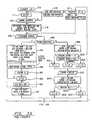
- the command to perform a certain tasksuch as a lock-related command (lock or unlock the doors, release the trunk), or to operate the lights and the horn or other alarm on the automobile in the event of a panic situation, or to cause cryptographic synchronization or resynchronization between the transmitter and the receiver module in the automobile, are under control of a plurality of buttons 12-15 disposed on a keychain fob or other hand-held transmitter unit shown in Fig. 1.
- the switches 12-15may be tactile or touch-type and feed a microprocessor 17 which is associated with a PROM 19, a RAM 20 and a ROM 21.
- the PROM 19is programmable only once, capable of having one set of output/input relationships burned therein, as is well known in the art. Typically, upon manufacture, each fob 16 will have its PROM burned in so as to establish a 16 bit identification number, which is not protected as secret information, as is described more fully hereinafter; two secret initial (seed) values from which encrypted messages are originated; and three secret feedback masks defining suitable polynomials for feedback exclusive ORing in the encryption process, for the life of the fob, all as is described hereinafter.
- the RAM 20is used as a scratch pad memory, in the usual way, and will contain changing values of the shift registers and commands, as described hereinafter.
- the program for the microprocessor 17is contained in the ROM 21.
- the microprocessor 17assembles a 64 bit command request word 25 which is applied serially over a line 26 to a suitable transmitter 27 (e.g., RF or infrared), which serially transmits the command request, as digital bits or otherwise, a suitable distance, such as not more than 10 meters.
- a suitable transmitter 27e.g., RF or infrared
- the fob 16will, before beginning its useful life, be associated with a particular automobile along with up to three more fobs (in the example herein) so as to form a set of up to four fobs, any one of which can operate the locks or the panic alarm of a related receiver module 30 in an automobile or other secured enclosure.
- the receiver module 30 in the automobileincludes a receiver 31 which receives the serial bits and applies them over a line 32 to a microprocessor 33, where the 64 bit word 25 is replicated in a 64 bit word 38.
- the microprocessor 33is powered from the automobile battery system 39.
- the microprocessor 33has an electrically erasable PROM 40, a RAM 41 and a ROM 42 associated therewith.
- Each fob 16is associated with a module 30 at a dealership, so that lost fobs may be replaced and matched to the module 30 anytime.
- a 64 bit word 25(Fig. 1) is formulated with each fobs' ID, secret initial values and masks, and a download signal is provided, in some fashion, by factory personnel on a line 49. This may be achieved by a jumper, or in any other suitable way, since it does not pose a security threat unless the receiver 30 is tampered with simultaneously, which can be avoided as described below.
- the 64 bit word 25 sent to the receiver module 30 during a downloadincludes one bit indicating the download operation. The presence of the download bit in the 64 bit word 38 (Fig.
- the word 25appears in Fig. 1 to be within a special 64 bit register. However, the word 25 actually appears in various parts of the RAM 20, in addresses designated to be used for holding the parts of the outgoing, serially transmitted word. Similarly, all of the apparent hardware within the microprocessor 17 is merely illustrative of processes and relationships, which may indeed be performed by hardware which resembles that illustrated in Fig. 1, or may be implemented, as is preferred, by processing of bits utilizing the RAM 20 as a scratch pad memory, by means of software which is well within the skill of the art ih the light of the teachings which follow hereinafter.
- the microprocessor 33has functions and processes illustrated therein which may either be hardware or software, as described with respect to Fig. 1 hereinbefore.
- Fig. 1The narrative with respect to Fig. 1 is of a form describing hardware: software implementation is described with respect to Figs. 3-7, hereinafter.
- the receiver module 30is connected to the locks 43 of the automobile, as well as to the automobile horn and lights 44, or other suitable alarm arrangements on the automobile.
- synchronizationBefore a fob can be utilized to operate the locks or alarms on an automobile, synchronization must occur. Herein, this is also referred to as resynchronization since it is utilized at different times during the life of the system, as described hereinafter.
- This resynchronization processis described hereinafter; suffice it at this point to say that the process will begin with the two secret initial (seed) values for the fob 16 located in a 20 bit linear feedback shift register (LFSR) 53, and a 19 bit LFSR 54, and suitable feedback masks for each of the LFSRs 53, 54 available at the input of corresponding feedback exclusive ORs 55, 56.
- LFSRlinear feedback shift register
- the initial synchronization(an initial resynchronization command) includes 20 iterations of the shift register 53 and at least 19 iterations of the shift register 54, so as to provide a complete bit-wise convolution.
- both shift registersmay be provided with 20 iterations during initialization (which is assumed herein).
- the high order bitis transferred by a line 61, 62 to the low order bit and is also exclusively ORed with those bits of the shift registers 53, 54 identified by bits in the feedback masks, to form the next higher order bits within the shift registers 53, 54.
- One embodiment hereinuses linear feedback shift registers, in some cases modified to be non-linear feedback shift register systems by shifting a pseudo random number of iterations as described hereinafter.
- pseudo random number generation techniquesmay be used such as linear congruential pseudo random number generators or non-linear congruential pseudo random number generators as more fully set forth in Chapter 3 of The Art of Computer Programming, Volume 2/Seminumerical Algorithms, ed.
- the pseudo random number generatorneed not be reversible.
- a reversible generatoris one where, given the current pseudo random number and complete knowledge of the generation process, the previous pseudo random number may be determined.
- a linear feedback shift register pseudo random number generatoris reversible.
- the pseudo random number provided by the iterations of the shift register 53is supplied over a trunk of 20 lines 68 to a 39 bit shift register 69.
- the shift register 69is associated with feedback 70 in the same fashion as the LFSRs 53, 54, with the exception that the shift register 69 is loaded with new numbers before each cycle of shifting feedback iterations. In this sense, then, the shift register 69 and feedback operate more as a cyclic redundancy code generator.
- the other input to the 39 bit shift register 69is a trunk of 19 lines 73 from a gate 74 that causes the low order 5 bits of the 19 bit LFSR 54 on a trunk of lines 75 to be exclusive ORed with 5 bits on a trunk of 5 lines 76 from a command register 77.
- the command register 77simply registers up to 32 commands encoded from the operation of any of the switches 12-15 (or fewer commands if some bits are used in a discrete fashion).
- the shift register 69In each cycle, there is presented to the 39 bit shift register 69 the outputs of the LFSRs with a command exclusive ORed in the low order bits of one of them. Then, the shift register 69 undergoes 39 iterations of LFSR-type feedback through an exclusive OR process 70, which utilizes a secret feedback mask provided by the PROM 19. This provides a full bit-wise convolution of the two words from the shift registers 53, 54, which is a cryptographic necessity.
- Use of the shift register 69may be employed in prior art systems, such as the two-generator embodiment of the Hill and Finn patent.
- the resultis an encrypted, key word provided on a trunk of 39 lines 80 to the 64 bit word 25, along with 16 fob ID bits from the PROM 19, a download bit 49 if appropriate, and a command flag such as a panic/resynch bit provided from the command register 77 on a line 81, when appropriate.
- a command flagsuch as a panic/resynch bit provided from the command register 77 on a line 81, when appropriate.
- both of the download and panic/resynch bitswill be 0's.
- an error correcting code circuit 83to create a 7 bit error correcting code component on a trunk of 7 lines 84 for the 64 bit word 25; typically, a single error correcting, multi-error detecting code (such as a Hamming code) will be used.
- the illustrated embodimentuses a linear feedback shift register as a cyclic redundancy code generator for encrypting the input into a key word.
- any of several well-known reversible encryption techniquesmay be used.
- McEliece error correcting code encryptionFor instance, the McEliece error correcting code encryption; the RSA cryptosystem; discrete exponentiation cryptosystem; linear or non-linear, full length or truncated congruential cryptosystems; or the DES cryptosystem, as more fully set forth in Chapter 10 of Contemporary Cryptology: The Science of Information Integrity, Simmons, ed., IEEE Press New York, NY (1992).
- the 64 bit wordWhen the 64 bit word is fully assembled, it is transmitted serially (bit-by-bit) or otherwise, by any well-known technique, through the transmitter 27 to the receiver 31 of the receiver module 30 to become the 64 bit word 38 therein. All of the bits of the word 38 are applied over trunks of 57 lines 90 and 7 lines 91 to an error correcting and detecting process 92. If a single bit error has occurred, a signal on a line 93 (as appropriate) will correct the bit that is in error. If a multiple bit error is detected, the process is totally void, and the receiver module 30 simply goes into a half second wait state, which simply slows down any attempts to crack the code which is being used, as is described more fully hereinafter. If a multiple bit error has occurred but is not detected, the cryptographic authentication process will almost certainly fail. On the other hand, if the error correcting code shows that the 64 bit word 38 has no errors, then a first OK signal is provided on a signal line 94.
- the ID of the fobreduces the probability that a command from a wrong fob will be cryptographically acceptable; it also reduces the amount of time it takes to iterate the code words in the receiver module to reach authentication (a match).
- there is no restriction on which fobs are assigned as a group to an automobileand it is assumed that there is approximately one chance in 11,000 that two fobs assigned to a particular automobile will have the same ID number.
- a feature of the inventionis that if one fob with matching ID does not become authenticated, the receiver module 30 will see if there is another assigned fob with that same ID number, and if so, attempt authentication.
- the 16 bit ID in the 64 bit word 38is provided over a trunk of 16 lines 97 to a 16 bit compare circuit 98, the other inputs of which, on a trunk of 16 lines 99, are provided by the ID register 100, which really represents four different locations in the EE PROM 40, one for each associated fob. If, indeed, the message has come from one of the four associated fobs, a second OK signal appears on a line 101, and the identification number of the fob which has sent the message is provided on a trunk of 4 lines 102 to the PROM 40 and to the RAM 41 so as to utilize in the ensuing decryption process the secret mask for the selected fob and the two LFSR values which have previously been created for that fob.
- the previous LFSR valuesare utilized, rather than the initial secret values, because, according to the invention, the LFSR values are built upon, with only one, two or three iterations for each command received by the receiver module 30.
- the 39 bit encrypted key wordis provided over a trunk of 39 lines 107 to a 39 bit shift register 108 which can be identical in either structure or function to the 39 bit shift register 69 in the fob, except that it is iterated in a reversing process.
- the reversing processis easily understood, one bit at a time, by considering how the received 39 bits got to be what they were.
- the shift register 69 and the exclusive OR circuit 70Fig. 1 if the high order bit (leftmost bit in Fig.
- the least significant bit in the shift register 108is a 1, it is applied to exclusive OR the bits of each order with the same secret mask which was downloaded for this fob originally. For any bit (such as the ninth bit) for which there is a corresponding bit in the secret mask, whenever the lowest ordered bit at the start of the iteration is a 1, that bit will be inverted from 1 to 0 or from 0 to 1. But if there is no corresponding bit in the secret mask, then the bit in question is simply advanced to the next lower order stage (in the example here, bit 10 becomes bit 9) without being inverted. Or, if the least significant bit (the rightmost bit in Fig.
- a fobOnce a fob is identified in the 16 bit compare circuit 98, its two secret feedback masks are loaded (from RAM 41) for use in corresponding exclusive ORs 113, 114, and its previously achieved 20 bit LFSR value is loaded into a 20 bit LFSR 115, while its previously achieved 19 bit LFSR value is loaded into the 19 bit LFSR 116.
- the LFSRis shifted (with or without exclusive ORing as described hereinbefore) either once or twice, in the case of the LFSR 115 or two or three times in the case of the LFSR 116 in dependence upon a pair of corresponding gates 117 which control the application of a clock 118 thereto, in the same fashion as described with respect to Fig.
- the 20 bits of the 20 bit LFSR 115 so generatedare applied over a trunk of 20 lines 123 to a compare circuit 124, to be compared with 20 bits provided from the 39 bit shift register 108 over a trunk of 20 lines 125.
- the high order 14 bits which are generated in the 19 bit LFSR 116are provided by a trunk of 14 lines 127 to the compare circuit 124 for comparison with 14 bits of the 39 bit shift register 108 provided on a trunk of 14 lines 128. Assuming that both the 20 bit and 14 bit words compare properly, this signals a successful authentication on a line 129 and the receiver module 30 is allowed to receive and respond to the command made by the fob.
- the only way to recover those bitsis to exclusive OR the low order 5 bit positions from the 19 bit LFSR 116 with the low order 5 bit positions of the reconstituted word in the 39 bit shift register 108. Therefore, the low order 5 bit positions produced by the 19 bit LFSR 116 are provided over a trunk of five lines 130 to a five bit exclusive OR circuit 131, the opposite inputs of which consist of the lowest order 5 bit positions from the 39 bit shift register 108 on a trunk of 5 lines 132.
- the result of the exclusive OR on a trunk of 5 lines 137comprise the command which is stored in a command register 138.
- the typical commands provided on a trunk of lines 139 to the locks 43comprise door unlock, door lock, and trunk release.
- Another command indicated by a signal on a line 140may comprise a panic command which will cause the horn and lights 44 (or other alarms) on the car to scare away a loiterer as the driver approaches the car with the fob (as described more fully hereinafter).
- the LFSRs 115, 116are cycled again. In each cycle, the LFSR 115 will be shifted once or twice depending upon the random bit utilized as a control over its gate 117, and the LFSR 116 will be shifted two or three times in dependence on the random bit utilized to control its clock gate 117. This is to allow the receiver module 30 to catch up, in cycles, and therefore in iterations, to the status of the LFSRs 53, 54 in the fob 16.
- buttons 12-15 on the fobwill undergo one cycle, and the shift registers 53, 54 will undergo one or two, or two or three iterations, respectively.
- the pressings of the buttons 12-15may occur simply by being crushed in a purse, children playing with the fob, or otherwise. Since each fob keeps its own LFSR generated numbers, and the receiver module 30 likewise maintains separate LFSR generated numbers for each fob, each fob will generally be able to track with the receiver module except for the inadvertent pressings of the switches 12-15.
- an 8 bit counter 143allows the receiver module 30 to try to catch up to the fob in question by repeating as many as 256 cycles, automatically. In a normal case, the receiver module 30 will catch up to the fob in only a few cycles.
- the receiver module 30is non-responsive to incoming signals while it is attempting authentication of a previous signal; the 256 attempts to catch up will transpire in only a half second or less; thus, authentication will not be hampered by repetitive pressing of the unlock button 13 due to impatience.
- the operatorwill understand that the receiver module is out of synchronization (cryptographic synchronization), and will press two buttons at one time (such as lock and unlock), or some other combination that will be recognized in the fob as a command to effect cryptographic resynchronization between the receiver module 30 and the fob 16, as well as to reinitialize following a loss of battery power (dead or changed), which allows the RAM data to disintegrate.
- a recognized command to synchronize(resynch command”, hereinafter) in the command generator 77 (Fig. 1) will produce the panic/resynch bit on the line 81.
- the resynchronization process in accordance with the present inventionincludes returning to the beginning; that is, returning to the use of the secret initial values and starting all over again.
- the resynch commandis used to initialize the units in the first place, and when they become out-of-synch, they are in a sense reinitialized just as when they are new.
- the panic/resynch bit on the line 81will cause the two initial secret values to be loaded from the PROM 19 to the LFSRs 53, 54 and the two initial secret feedback masks to be made available to the exclusive ORs 55, 56, and the 39 bit secret feedback mask to be made available to the exclusive OR 70.
- the panic/resynch command on the line 145causes the clocking gates 64 to cause 20 iterations, respectively, of the LFSRs 53, 54. The purpose is that, utilizing as many iterations as there are bits in the word, causes the maximal mix of the feedback, regardless of what the mask is, to assure complete bit-wise convolution.
- the eight low order bit positions of the shift register 53are provided with a truly random number on a trunk of 8 lines 146 from an 8 bit counter 145 which is allowed to respond to the clock 65 in a manner related to pressing of the buttons 12-15, as described with respect to Fig. 3 hereinafter. Since it is impossible for persons to depress buttons carefully enough to achieve other than a random number at computer clocking frequencies (500 KHz or more), the likelihood of this number being exactly the same in successive resynch processes is extremely small.
- outputs of the 20 bit LFSR 53 and the 19 bit LFSR 54are provided to the 39 bit shift register 69.
- the shift register 69thereafter undergoes 39 feedback shifting iterations, of the type described hereinbefore, to produce the 39 bit encrypted word in the 64 bit word 25.
- the 16 bit ID for the fobis provided to the word 25, along with a panic/resynch bit (described hereinbefore) to indicate that this is a panic or resynch request, and the error correction code is computed and the code bits added to the word 25 as described hereinbefore.
- the first two stepsare the same as in a normal command. Error correction is provided if possible, and if the word is correct, the first OK signal appears on the line 94. Then, the four possible IDs are compared with the incoming ID in the word 38, and if there is a match, the second OK signal appears on the line 101 and the signals on the trunk of four lines 102 tell the EE PROM 40 which fob is being worked with and therefore which of the sets of two secret initial values and three secret feedback masks should be utilized. The appropriate secret initial values and three feedback masks are loaded into the LFSRs 115, 116, and the exclusive ORs 113, 114 and 109.
- the content of the 39 bit shift register 108is reconstructed by 39 reverse iterations, as described hereinbefore, so as to recover the word in the 39 bit shift register 69.
- the output of the 20 bit LFSR 53does not reflect 20 shift iterations of only the secret initial value that was placed therein, but rather represents 20 iterations of 12 high ordered bits of the secret initial value and 8 random low ordered bits
- comparisons with the high order bits of the 39 bit shift register 108cannot be made in the receiver module 30.
- the 20 bit LFSR valuemust be recovered in the same way that the 39 bit shift.register value is recovered. That is, a reverse linear feedback shift register operation, utilizing the exclusive OR mask with the least significant bit, is achieved in a 20 bit LFSR 151 (Fig.
- the next step in the resynch processis to compare the high order 12 bit positions of the reconstituted word in the LFSR 151 with the 12 bits of the secret initial value of the 20 bit LFSR 115.
- the 12 bits on the trunk of 12 lines 160are compared with the 12 bits on the trunk of 12 lines 161, which are created solely in response to the initial secret value.
- the 14 bits on the trunk of lines 127are compared with the 14 bits on the trunk of lines 128; these should also compare because the 19 bit LFSR 116 has been passed through 20 iterations in response to its secret initial value so it should match the result in the 19 bit LFSR 54, the 14 high order bit positions of which have been reconstituted in the 14 bits of the 39 bit shift register 108 to which the trunk of lines 128 respond.
- the panic/resynch command on the line 150may be deemed to be a panic command, if desired, even if not decoded. Up to this point, the panic command and the resynch command are identical.
- the next step in the resynch processis to compare the 8 bit random number in the low ordered bit positions of the 20 bit shift register 151 with the last four prior low order 8 bit random numbers received during resynchronizing.
- the random numberis compared with the last four such random numbers previously received by providing the 8 low order bit positions of the 20 bit LFSR 151 on a trunk of 8. lines 153 to 8 bits of the compare circuit 124 which are also responsive to a trunk of 8 lines 154 from a first in, first out stack 155 (actually embodied in the EE PROM 40), which keeps track of the last four 8 bit random numbers received during resynchronization operations.
- the 8 central bits of the compare circuit 124compare with any of the four 8 bit words in the first in, first out stack (FIFO) 155, the operation is a failure, and the receiver module 30 reverts to a half second wait period before it will react to the next command (as described hereinafter) and the matched word goes to the head of the stack and remaining words in the FIFO are adjusted accordingly.
- the 8 bit word on the trunk of lines 153does not compare with any of the bits in the stack 155, the comparison is a success and the operation can proceed; additionally, the 8 bit word on the trunk of 8 lines 153 is applied over the trunk of lines 154 to the FIFO stack 155, for comparison with subsequent random 8 bit words during subsequent resynchronization operations. In such a case, the new word goes in the FIFO and the oldest word is dropped out of the FIFO.
- the resynchronization operationis complete.
- the resynchronizationis commanded, after successful comparisons of the 12 high order bits and the 14 bits as described hereinbefore and no comparison with the FIFO, the values established in the shift registers 53, 54, 115 and 116 are left as they are, for use in authenticating the next normal command cycle.
- the panic commandis the same as has been described with respect to the resynch command, except that, if the command register 138 produces the panic command signal on the line 140, the lights and the horn 44 (or other alarm) are operated, and, all of the LFSRs 53, 54, 115, 116 are then restored to whatever setting they had immediately before sending and receiving the panic command.
- the panic commandoperates differently from lock, unlock and trunk release commands, so that there will be response, even with total missynchronization between the fob and the receiver module. In the case of the panic command, starting over with the secret initial values ensures that authentication (to avoid nuisance responses) will be successful on the first try. Therefore, the panic command in the fob (Fig.
- the fobcomprises a microprocessor, such as a 68HC11, which has a stop mode in which the clock is stopped, the power consumption is negligible, and the only thing the processor can do is to respond to an external interrupt to get started again.
- a microprocessorsuch as a 68HC11
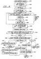
- application of battery powerwould cause the program to be reached through a power up entry point 170 and the processor would immediately stop at a step 171 where the only function is to perform a test 172 to determine whether any of the buttons 12-15 have been pressed, or not. So long as no button is pressed, the processor waits in a low power stop mode, in the loop 171, 172.
- an affirmative result of test 172reaches steps 173 in which a switch word in RAM 20 is ORed with the one of the switches which was pressed.
- a switch word in RAM 20is ORed with the one of the switches which was pressed.
- two switchescannot be pressed within a few computer clocks of each other, so the first one will be sensed.
- a second oneis pressed within about 1/2 to one second, it will be treated as paired-up with the first; if the two are correct (e.g., lock and unlock) a resynch command is declared.
- a switch interruptselectively enabled during normal command cycles only, allows sensing the second switch of a resynch.
- the steps 173also enable the switch interrupt and start the random counter.
- a decode command subroutine 179is performed and a test 180 determines if the command is either panic or resynch. If so, an affirmative result of test 180 reaches a series of steps 181 in which the shift register contents are saved in buffers, the panic/resynch (P/R) bit on line 81 is set to 1; a working register, herein referred to as a "shift register" (SR), is set with the random counter in its low order 8 bit positions and with the higher order bit positions equal to a 12 bit secret initial value for the 20 bit LFSR, the mask associated with the SR is set equal to the 20 bit secret feedback mask from the PROM 19, and a cycle counter C is set to 20 iterations.
- P/Rpanic/resynch
- SRshift register
- a bitwise linear feedback shift register iteration subroutine 182is performed in which each bit is shifted to the next higher order position, with or without inversion, dependent upon the secret mask and/or whether the low order bit position has a 1, as described hereinbefore. Then the C counter is decremented in a step 183 and a test 184 determines if a complete, 20 iteration LFSR cycle has yet occurred. If not, another iteration is performed by the subroutine 182 and the C counter is decremented again. After 20 iterations, an affirmative result of the test 184 reaches a step 185 where the 20 bit shift register storage location in RAM 20 is set equal to the content of the working shift register.
- the steps and test 182-185comprise an LFSR cycle 186.
- the 19 bit shift register 54is prepared in a series of steps 190 in which the content of the shift register is set equal to the content of the 19 bit secret initial value in the PROM 19, the mask associated with the shift register set equal to the 19 bit secret feedback mask in the PROM 19, and the C counter is set equal to 19. Then an LFSR cycle subroutine 191 (similar to the subroutine 186) is performed. Then the 39 bit shift register 69 is prepared for its LFSR cycle in a series of steps 192.
- the 5 low order bit positionsare the exclusive OR of the command with the 5 low stages of the 19 bit shift register 54; the high 14 bits of the 19 bit shift register 54 are placed directly in the 39 bit shift register; and the highest order 20 bit positions are set equal to the 20 bit positions of the 20 bit shift register 53.
- the maskis set equal to the secret feedback mask for the 39 bit shift register, found in the PROM 19, and the C counter is set to 39. Then, an LFSR cycle subroutine 193 is performed, this time with 39 iterations, and the result restored in the 39 bit shift register embodied in the scratch pad memory 20.
- a routine 194the 16 bits of the fob ID from the PROM 19, the 39 encrypted bits now in the 39 bit shift register, the P/R bit, and the download bit are all transmitted serially while the calculation for error correcting code bits is performed. These are calculated and transmitted, to complete the process of a panic or resynch command transmission. Whether it be a panic or a resynch is determined by the status of the five command bits. If a resynch was performed, the new values of the 20 bit shift register and 19 bit shift register will be retained as the pseudo random starting words to be used for future authentication of transmissions to the receiving module. But if this is a panic command, the new values are only used to ensure synchronized response, one time, and a test 195 causes the previous values of the 20 bit and 19 bit shift registers to be restored from the buffers in a step 196.
- a negative result of the test 180reaches a series of steps 199 in which the working shift register is set equal to the 20 bit shift register in the RAM 20 (not the secret initial value), so as to take advantage of the pseudo random number generated by all of the previous iterations.
- the mask for the shift registeris set equal to the 20 bit shift register secret feedback mask from the PROM 19, and a set of random bits (which determines how many iterations are to be performed, similar to the gates 64 of Fig. 1) is set equal to whatever random bits have been selected to be used to control the iterations for the 20 bit shift register.
- a pair of tests 200determines what the random bits are: if both are a 1, a step 201 sets the C counter to 1; if both are a 0, a test 202 sets the C counter to 2. But if they are different, a step 201a sets the C counter to 3. Then, either a 1 iteration, 2 iteration or 3 iteration LFSR cycle subroutine 203 is performed.
- the method of the inventionmay be used in prior art systems, such as in the Hill et al patent.
- a series of steps 204set the working shift register equal to the content of the 19 bit shift register in the ram 20, the mask for the working shift register is set equal to the secret feedback mask for the 19 bit shift register in the PROM 19, and the random bit is set equal to whatever bit has been chosen to be random for the 19 bit shift register.
- a test 205determines if the random bit is 1, or not. If it is, a step 206 sets the C counter to 3, and otherwise a step 207 sets the C counter to 2. This provides four iterations (201, 206; 202, 207) whether the random bit is 1 or 0; but it may be set in other ways, if desired.
- a 2 or 3 iteration LFSR cycle subroutine 191is performed.
- the series of steps 192set things up so as to form the 39 bit encrypted word
- a 39 iteration LFSR cycle subroutine 193is performed so as to produce the 39 bit encrypted word
- the subroutine 194transmits all the bits together with a calculated error correction code.
- the differences between encrypting and transmitting normal commands and the panic/resynch commandare the setting of the P/R bit, the use of the random counter 145, the use of the secret initial values and the particular code which is exclusive ORed into the 19 bit shift register 54.
- the programadvances to a one-half second wait in a step 208. This is to ensure that successive button pressings which are independent of each other will occur no closer than one-half second apart.
- a switch interruptmight have occurred as a result of a second pressing of one of the switches 12-15. As described hereinbefore, this is most likely the case of an attempt to press two switches at once (such as lock and unlock) to thereby cause a resynch.
- a test 211determines if the resynch flag has been set. If it has, an affirmative result of test 211 reaches a step 212 which resets the resynch flag, and then the program advances to the decode command subroutine 179. If the first switch which was pressed, turning on the computer, was either lock or unlock, and the second switch which was pressed, causing the switch interrupt, was either unlock or lock, respectively, then the decode command subroutine will in fact decode a resynch command, to cause a resynch operation of the type described hereinbefore.
- any other two-key seriesmay be decoded into a lock command for security, or into a panic command since the panic command will not affect security, or it could cause reversion to the one-half second waiting period, at step 208, or otherwise as suits any particular implementation of the invention.
- the decode command subroutinewill decode a resynch command without the aid of Fig. 4 and the resynch flag. If switches are repetitively pressed at less than half-second intervals, the switch word will either contain gibberish or will simply repeat the resynch command.
- Fig. 5It is assumed that the decryption of Fig. 5 is carried out in a microprocessor of the same general type as is used in the fob.
- the routineWhen connected to a battery, the routine is entered through a power up transfer point 214 and the processor immediately goes into a stop mode at a step 215, where the clock is off and the only function is to respond to a receiver interrupt at a test 216.
- the processor in the automobileIn between usages, the processor in the automobile will remain in the stop mode, in the loop 215, 216.
- an affirmative result of the test 216will reach a subroutine 217 which handles receiving all 64 bits of the word transmitted from a fob, calculating the error correcting code, and fixing any single error which can be fixed.
- test 218determines if the error correction code indicates correct data. If it does not, a negative result of test 218 reaches a transfer point 219 and then a step 220 where the program just waits for half of a second. The purpose of this is to severely hamper any attempts to break the code through repetitive application of numbers, with or without calculated likely candidates. After waiting one-half second, the processor returns to the stop mode in the loop 215, 216.
- na working number
- na working number set equal to 4 (or to such other number as the number of fobs which can be associated with the automobile).
- a subroutine 223compares all the bits of the incoming ID number to all the bits of the ID number for fob 4. If they are not equal, a negative result of a test 224 will reach a step 225 where n is decremented and a test 226 determines if all of the fobs have been checked or not. If they have, that means a signal has been received from a fob of another automobile by accident, or from some other unauthorized source.
- an affirmative result of test 226is taken to be a failure, and the wait step 220 is reached through the wait transfer point 219. Otherwise, the ID of another fob is checked in the subroutine 223. Assuming that the ID number matches for one of the fobs, another working number, N, is set equal to n so as to identify the words in the PROM and RAM needed for decryption, in a step 227. Since the received word may relate to a fob other than fob N, but having the same ID number, the shift register values for fob N are saved in a buffer, in a pair of steps 228, so they may be restored if authentication fails.
- a test 229determines if the P/R bit was present in the incoming word, or not. If it is present in the incoming word, the panic/resynch decrypt routine of Fig. 6 is reached through a transfer point 230.
- the first steps 232set a main working shift register (SR) and its mask equal to the secret initial value and the secret feedback mask for the 19 bit LFSR, respectively, from the PROM 40 for the selected fob N, and a C counter is set equal to 20 so as to cause 20 iterations. Then, a 20 iteration LFSR cycle subroutine 233 is performed on the 19 bit shift register. It is assumed that the 39 bit encrypted word portion of the 64 bit received word 38 is stored immediately in a 39 bit shift register location within the RAM 41, which is where it now can be found. Then the 39 bit encrypted word, in the 64 bit word 38, and the 39 bit secret mask for the fob N are provided to the shift register and the C counter is set for 39 iterations, in step 234.
- SRmain working shift register
- a bitwise reverse LFSR iteration subroutine 235is performed which looks at the low order bit to determine whether the bits corresponding to the mask should be flipped before they are shifted to the next lower order position in the shift register to reconstitute the original word prior to encryption.
- the C counteris decremented in a step 236 and when all 39 iterations have been performed, an affirmative result of a test 237 will reach a step 238 wherein the content of the working shift register is stored in the 39 bit shift register in RAM 41.
- the steps and tests 235-238comprise a reverse cycle subroutine 239, which recovers the initial unencrypted value of the concatenation in the 39 bit shift register 69 in the fob.
- Bits 19-38 of the decrypted 39 bit shift registerare now loaded into the working shift register in steps 242, the mask for the shift register is set equal to the 20 bit secret feedback mask for fob N from the EE PROM 40, and C is set equal to 20, and a 20 iteration, reverse LFSR cycle subroutine 243 is performed to recover the combined word (initial value plus random).
- a subroutine 244there is a bitwise comparison of the 39 bit shift register bits 27-38 with the twelve bits of the 20 bit secret initial value for fob N, from EE PROM 40, and of bits 5-18 of the 39 bit shift register with bits 5-18 of the 19 bit shift register for fob N, which are found in the RAM 41.
- test 246determines if the panic/resynch bit was established in response to a resynch command. If not, the panic command is performed by turning on the lights, horn, or other alarm of the automobile in a step 254. Then, the shift registers for fob N are restored in the steps 250 and the wait step 220 is reached through the transfer point 219.
- a positive result of test 253reaches a subroutine 255 which compares bits 19-26 of the 39 bit shift register (the regenerated random number) to a queue of previously used random numbers in the first in, first out stack (FIFO) 155, in EEPROM 40. If the random word compares to any of the last four (or whatever size FIFO is chosen) random words in the queue which were used in resynchronization, the resynchronization is deemed to be unsuccessful, since it is assumed that there has been clandestine playback of a copied random word.
- an affirmative result of a test 256reaches a subroutine 257 that rearranges the FIFO stack by moving the random word from its position in the queue in the FIFO stack to the first position thereof, and adjusting the position of the other words in the queue, without losing any. And, since this is deemed to be an unsuccessful attempt to resynchronize the unit, the old values in the 19 bit and 20 bit shift registers for fob N are restored in the steps 250. Then, the wait step 220 is reached through the transfer point 219.
- the resynch operationis successful, so the steps 250 are bypassed and the setting of the 19 bit shift register for fob N in RAM 20 is left as it was established by the resynchronization operation, at subroutine 233.
- the 20 bit LFSR word created in the subroutine 243is placed in the RAM for fob N (step 259), for use en futuro.
- Resynchronizationoccurs only after: 20 iterations of the 19 and 20 bit shift registers from their secret initial values and the random number; performing 39 iterations in the 39 bit shift register with those values, and the exclusive OR of the command; reverse iterations of the 39 bit encrypted word in the receiver module; reverse iteration of the 20 bits which include the secret initial value of the 20 bit shift register and the random counter; generation and successful comparison of the high order bits of the 19 bit shift register; and a failure of comparison of the random word with any of the last four random words used to resynchronize the system. This is quite secure.
- the try counter 143is set to its maximum count in a first one of a series of steps 262. Then, the working shift register (SR) is set equal to the 39 bit shift register in the RAM 20, which contains the 39 bit encrypted word.
- the mask for the shift registeris set equal to the 39 bit secret feedback mask in the EE PROM 40, the C counter is set equal to 39, and a reverse LFSR cycle subroutine 267 is performed.
- a series of steps 271cause the contents of the 20 bit shift register for fob N to be loaded from the RAM 41 into the working shift register (SR), the mask for the shift register is set equal to the secret feedback mask for fob N in the EE PROM 40 and a random bit is set equal to whatever bit or bits have been chosen for the 20 bit shift register (as described with respect to steps 199 in Fig. 3). Then the random bits are tested in a pair of steps 272, and if both are a 1, the C counter is set equal to 1 (step 273), if both are a 0, the C counter is set equal to 2 (step 274), and otherwise the C counter is set equal to 3 (step 274a). Then, an LFSR cycle subroutine 275 is performed.
- a series of steps and tests 276-279prepare to run an LFSR cycle subroutine 280 for the 19 bit shift register in a similar fashion.
- a subroutine 284does bit-by-bit comparisons of the 39 bit shift register to the 20 bit shift register and to the high order bit positions of the 19 bit shift register, for fob N. If all the bits are equal, an affirmative result of a test 285 causes the particular command to be found by exclusive ORing the 5 low order bits in a subroutine 286 and the command is performed in a step 287, such as locking or unlocking the door, or releasing the trunk lid.
- a negative result of test 285reaches a step 288 where the try counter is decremented and a test 289 to determine if 256 tries have been made yet. If not, another pair of iterations 275, 280 are performed and compared. This goes on until the receiver module 30 catches up with the fob 16 (if it can). If after 256 tries, a comparison has not been reached, an affirmative result of test 289 will reach a test 290 to see if all the fobs have been given consideration. If not, the restoration steps 249 (Fig. 5) are reached through the transfer point 248. Otherwise, the shift registers for fob N are restored to their starting values in steps 292 and the program reverts to the wait step 220 (Fig. 5) through the transfer point 219.
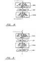
- an alternative random iterationutilizes a pair of bits from the random counter to determine the number of iterations of the 20 bit shift register operation and one bit thereof to determine the number of iterations in the 19 bit shift register operation.
- the cycle counter, Chas its two low ordered bit positions (0, 1) set equal to the selected bits (3 and 6 in this example) of the random counter, and it is incremented to ensure that a zero-valued pair of bits will not result in no iteration.
- steps 204areplace steps and test 204-207 to provide one or two iterations in the 19 bit operation.
- the random numberis found at the head of the queue in the FIFO memory (40) for fob N.
- Steps 271areplaces steps and tests 271-274a and steps 276a replace steps and tests 276-279.
- the number of iterations in each caseis one higher (1-4; 1 or 2) than the value of the bit or bits (taken together as low ordered bits) selected from the random counter.
- fewer choices of the number of iterationsmay be used in response to random counter bits, as in tests 200 and 272, or by means of any other decode. Of course, more bits and higher numbers may be used.
- the systemmay be utilized without the use of ID numbers, simply by trying all of the sets of stored shift register words and masks; this would make the system subject to more nuisance iterations since the ID number would no longer screen out many transmissions from similar, unauthorized systems.
- ID numberswould be used to correlate the generated pseudo random words with the correct feedback mask for subsequent iterations, as well as with the correct initial value. This may be achieved by arbitrary numbering of the various sets of initial values and masks and corresponding registers for storing the iterated words.
- the various number of iterations used during synchronizationmay be the same (e.g., 20, or more) for both random words generated from initial values, or they may be different (e.g., 20 and 19, or more).
- the term "encryption"inherently defines a process capable of decryption.
- the process of encryptionemploys a pseudo random number generation operation of any type, that generation operation must be capable of being practiced in reverse, such as the reverse LFSR operation utilized herein.
- the encryption processes and operations used hereinmay be any of those described hereinbefore by way of example, and others.
- the LFSR pseudo random number generation operationis one of the easier ones to understand, and probably the simplest to implement in dedicated or quasi-dedicated hardware. That is, if the signal processing means of the invention includes dedicated shift registers and the like as may be implied in Figs. 1 and 2, the LFSR form of encryption may be preferred.
- secret initial values and secret feedback masks for generating maximal length sequences of pseudo random numbersare essentially unique to each transmitter, but not necessarily totally unique.
- sets of two secret initial values and three secret feedback masks, taken together,are capable of distinguishing more vehicles than are made in a lifetime; however, the method of assignment, or human error or design, could result in some few with the same set of numbers.
- the use of a 16 bit identification numbermeans that there will be several fobs each year possibly having the same identification number (but not the same secret values) so that over a course of time, there could be many fobs (such as about 5,000 fobs in the USA over a 10-year period for each possible identification number). Within statistical probability, it is possible that as many as one out of 10,000 automobiles having four fobs each may have two fobs with the same identification number. It is an important aspect of the present invention, that even if one fob having a correct identification number is not authenticated within 256 tries (or whatever is used), it will nonetheless try any other fob that may have the same ID number.
- the last tried fobis likely to be reported as faulty, and a new fob issued, with very minuscule likelihood that the new fob would have the same identification number as the remaining fobs in the set.
- each encryption(such as the 19 bit, the 20 bit and the 39 bit shift register encryptions) are the same (linear feedback shift register pseudo random number generation). However, they need not all be the same, and in fact can be different algorithms to further confuse any attempted analysis.
- the number of bits in the shift registerscan be whatever is desired. In all cases, the greater number of bits, the harder to break the code by analysis.
- the numbers used hereinprovide a safe system, but greater or fewer numbers of bits may be chosen in practicing the invention if desired.
- the wordsmay be considered to be single words, or double words in the sense that the 19 bit shift register produces one portion of 14 bits which is used for cryptographic authentication, and another portion which carries the command but is not used in cryptographic comparison for authentication.
- the 20 bit shift register operationmay employ one through five iterations, dependent upon the random occurrence of a pair of bits within the register, or a pair of random bits.
- the 19 bit shift register operationmay employ one through three iterations, depending upon one of its bits or a random bit.
- these numbersmay as well be reversed, they may be the same, they may depend on each other or on any pseudo random events that can be duplicated in the receiver, and/or either of them may be greater, provided that time constraints do not prohibit a greater number of iterations, and that every possible condition results in at least one iteration.
- the small number of iterationswould not be important but for the fact that in any given transmission, the receiver is allowed up to 256 attempts to catch up, iteratively, to the encryption process for the given transmitter (or for several transmitters). There is even more flexibility when the variable iterations are used in a pseudo random number generator in other than transmitter/receiver environments (such as in computer processes).
Landscapes
- Engineering & Computer Science (AREA)
- Computer Security & Cryptography (AREA)
- Computer Networks & Wireless Communication (AREA)
- General Physics & Mathematics (AREA)
- Theoretical Computer Science (AREA)
- Physics & Mathematics (AREA)
- Signal Processing (AREA)
- Mathematical Analysis (AREA)
- Mathematical Optimization (AREA)
- Pure & Applied Mathematics (AREA)
- Computational Mathematics (AREA)
- General Engineering & Computer Science (AREA)
- Computing Systems (AREA)
- Lock And Its Accessories (AREA)
Description
- This patent application is a divisional application of European PatentApplication number 94923275.5, which claims a method of cryptographicauthentication of transmissions from a transmitting unit to a receivingmodule, a method of cryptographically authenticating transmissions fromany of a plurality of remote command transmitting units to a commandperforming receiving module, a method of synchronized cryptographicauthentication of transmissions from a remote command transmitting unitto a command performing receiving module selectively responsive theretoand a cryptographically authenticated remote control system in which acommand transmitting unit may selectively cause a physical effect in acommand receiving module rendered responsive thereto, as describedherein.
- This invention relates to pseudo random numbersand cryptographically encoded transmissions, such asthe type involved with an automobile key chain fobtransmitter which opens the automobile door locks ortrunk in response to transmissions from the fob.
- The art of encoding transmissions so that thetransmissions may be authenticated at a receivingmodule must meet criteria for technical viability(security) as well as low cost and convenience. Thecost and convenience criteria result in an inabilityto use any encoding with polynomials of excessivedegree (such as binary numbers of hundreds of bits).Furthermore, cryptographic processing must requireless than one second for acceptability by the user.Cost and weight constraints can limit the size andsophistication of a microprocessor or other signalprocessing equipment used in the system.
- An example of such a system is disclosed incommonly owned U.S. Patent 5,191,610 to Hill and Finn.That system utilizes linear feedback shift registerpseudo random number generation having the same seednumber and the same, fixed feedback mask in thereceiver as in the transmitter. The number ofiterations of linear feedback shift register pseudorandom number generation are counted in both thereceiver and the transmitter, there being oneadditional iteration each time that a command is sent.Should the receiver not recognize one of thetransmissions (because the transmitter was inadvertently activated at a great distance from thereceiver, or otherwise), the receiver is allowed amoderate number of catch-up iterations in which itattempts to match the received transmission. Shouldthat fail, the transmitter tells the receiver how manyiterations from the seed it should perform in order torecreate a new current pseudo random number in orderto resynchronize the receiver to the transmitterpseudo random number.
- The aforementioned system requires that areceiver and a transmitter be wired or loaded with abinary feedback mask at the factory and sold as apair. It also precludes matching a replacementtransmitter with an existing receiver without theinvolvement of dealership personnel, which couldcompromise security. The pseudo random numbergenerators of the Hill and Finn patent use oneiteration per encrypted message. This saves time butresults in a certain level of correlation betweensuccessive samples, so that the samples are lessrandom-like. In other pseudo random numberapplications, the speed advantage of theaforementioned system could be useful but for theinherent correlation.
- Any such system, except one that uses a trulyrandom number of infinite degree, can be compromisedeither by analysis of a succession of interceptedsignals, or by a brute force, exhaustive numericaltrial approach which simply tries every numberpossible as the authentication word (the code or key).
- Coded keypads used for unlocking vehicles haveinherent security features. The generation of thecode word by pressing keys can be shielded from view,and is certainly not capable of being determinedbeyond a line of sight. Furthermore, there would be great risk for an intruder entering every possiblenumber into a keypad in an attempt to replicate thecode (unless, of course, the automobile were parked inan unobservable area, such as a private.or otherwisevacant garage). Thus, the keypad cannot be breachedby analysis, and is not likely to be breached bynumerical trial.
- In contrast, lock systems which employ remotetransmissions are enormously subject to securitytampering because the surveillance of thetransmissions may be carried out in another vehicle,without attracting any attention whatsoever.Therefore, it is possible to record many transmissionsto a given vehicle, such as in a reserved workplaceparking space (which commonly contains expensivecars), as well as providing an unobservableopportunity to attempt the breach of a security system(or even several systems at one time) by broadcastinghuge volumes of random numbers, in parking lots wherevehicles remain for long periods of time, such as atairports.
- Whenever a transmitter is newly assigned to beused with an existing receiver, it is not sufficientto allow the new fob to identify itself and becomeauthorized, without limiting that activity to a timewhen there is authorized access to the receiverthrough other than the transmitter itself (that is,within the vehicle itself). Thus, access to thevehicle by means of a traditional key or the likeassures the safety of matching a newly assignedtransmitter to an existing receiver. In the case ofloss of synchronization between the transmitter andthe receiver, simply allowing the receiver tosynchronize to a particular pseudo random numberprovided thereto by the transmitter makes it too easy for a surreptitious breach of security based on the analysis of a fewtransmissions, and synchronizing thereafter to one of the previous transmissions,utilizing numbers expected to be successful based upon analysis. Mereobfuscation of the resynchronizing code could be compromised by analysis ofsuccessful resynchronizations, and determination of the obfuscation function.The danger is not just that a single car might be broken into, but that asophisticated capability might be developed and thereafter utilized extensively tobreach the security of a large number of automobiles of a similar type.
- European Patent Specification No. 0283758 discloses an automatic pseudo-randombit sequence generator which performs a variable number of iterationson a starting number.
- The present invention provides a method as defined in
Claim 1hereinafter. - The method may include the features of any one or more of
dependentClaims 2 to 10. - An advantage of the present invention may be to provide rapid pseudorandom number generation with minimal correlation.
- This invention is predicated on our observation that introducing nonlinearitiesinto the Galois field operation of linear feedback shift register pseudorandom numbers can render a code very difficult to breach by or with aid fromnumerical analysis. The invention is further predicated on the fact that timeconstraints on authentication can render the numerical trial approach essentiallyuseless. The invention is predicated in part on the reversibility characterisitic ofthe well-known exclusive OR operation, and on the reversibility of encryptionsuch as encryption involving linear feedback shift register operations.
- According to the invention, as claimed in the corresponding parentapplication, an encryption, such as linear feedback shift register pseudo random number generation operation, is performed on a word comprising a pair ofconcatenated, independently generated numbers, which may themselves beencrypted (such as pseudo random numbers) and the result transmitted to areceiving module where a decryption, such as a reverse pseudo random numbergeneration operation, recovers the concatenated numbers for cryptographicauthentication. In accordance further with the invention, the encryption anddecryption are performed with a secret mask essentially unique to thetransmitter. According further to the invention, an encrypted number, such as apseudo random number, used for cryptographic authentication containscommand bits exclusive ORed into at least a portion thereof.
- According to the invention, a number which may be utilized inauthentication of command transmissions, is generated by the iterativeencryption process, such as a linear feedback shift register pseudo randomnumber generation operation, which has a variable number of iterations perauthentication, the number varying in response to a pseudo random event.According further to the invention, a pair of pseudo numbers are iterativelyencrypted, such as by linear feedback shift register pseudo random numbergeneration operations, using a different number of iterations in each successiveencryption, the sequence of the number of iterations of one of them beingdifferent from the sequence of the number of iterations of the other of them, said number of iterations being based uponrespectively different pseudo random events related tothe respective words.
- According to the invention of the parent application a plurality oftransmitters are usable with a single receiver bymeans of secret numbers (such as initial values andfeedback masks for feedback shift register encryption)essentially unique to each transmitter which arereplicated in any receiver with which a transmitter isto be used, the receiver being capable of determiningif each received transmission can be authenticatedutilizing the initial values and masks of any of itsassigned transmitters.
- In accordance with the invention of the parent application theinitial secret values and feedback masks oftransmitters to be associated with a given receiverare stored (such as in an erasable read-only memory)by downloading the secret numbers of a transmitterinto a receiver, thereby permitting the addition of atransmitter to the family of transmitters to which areceiver can respond. Although this may be performedat a dealership, it does not require, nor need itpermit, human knowledge of the precise numbers;therefore, the possibility of surreptitious access isnearly eliminated. In further accord with theinvention, identification numbers are associated withthe secret numbers of each transmitter, which pre-screentransmissions before authorization attempts,thereby reducing nuisance operations from similar,unauthorized transmitters, and reducing the timerequired for multiple authentication attempts
- According to the invention of the parent application the reception ofeach word causes the receiver of a remote operatingsystem to become unresponsive to further transmissionsfor a period of about one-half second or more, thereby significantly inhibiting the capability to breach thesecurity thereof through exhaustive numerical trials.
- According to the invention of the parent application cryptographicauthentication of transmissions from a remotetransmitter to a receiver module involves encryption,such as by linear feedback shift register pseudorandom number generation operations, utilizing secretfeedback masks which are essentially unique to eachtransmitter, and replicated only in a receiver whichis to respond to the related transmitter.
- Random iterations reducecorrelation between successively generated pseudorandom numbers. Cooperative use of all of theaforementioned features in a remote operating systemrenders the system extremely difficult to breach byanalysis; and use of a half-second delay, for example,causes a 50% statistical probability of a 39 bitencrypted key word being breached by exhaustivenumerical trials to require more than one month.
- The invention may be used in remote systemsother than automobile lock systems.
- Other objects, features and advantages of thepresent invention will become more apparent in thelight of the following detailed description ofexemplary embodiments thereof, as illustrated in theaccompanying drawing.
- Fig. 1 is a stylized, simplified schematic blockdiagram of a transmitter according to the inventionof the parent application in which the method of the present invention maybe used.
- Fig. 2 is a stylized, simplified schematic block diagram of areceiver according to the invention of the parent application.
- Fig. 3 is a logic flow diagram of a transmitter encryption routine.
- Fig. 4 is a logic flow diagram of a switchinterrupt subroutine.
- Fig. 5 is a logic flow diagram of a firstportion of a receiver decryption routine according tothe invention of the parent application.
- Fig. 6 is a logic flow diagram of a paniccommand or resynch command portion of a decryptionroutine according to the invention of the parent application.
- Fig. 7 is a logic flow diagram of a normalcommand authentication portion of a decryption routineaccording to the invention of the parent application
- Figs. 8 and 9 are logic flow diagrams ofalternative routines for pseudo random iterations.
- One example of the present invention may be usedin a remote, encrypted automobile door and trunklocking and unlocking mechanism. The command toperform a certain task, such as a lock-related command(lock or unlock the doors, release the trunk), or tooperate the lights and the horn or other alarm on theautomobile in the event of a panic situation, or tocause cryptographic synchronization orresynchronization between the transmitter and thereceiver module in the automobile, are under controlof a plurality of buttons 12-15 disposed on a keychainfob or other hand-held transmitter unit shown in Fig.1. The switches 12-15 may be tactile or touch-typeand feed a
microprocessor 17 which is associated withaPROM 19, aRAM 20 and aROM 21. ThePROM 19 isprogrammable only once, capable of having one set ofoutput/input relationships burned therein, as is wellknown in the art. Typically, upon manufacture, eachfob 16 will have its PROM burned in so as to establish a 16 bit identification number, which is not protectedas secret information, as is described more fullyhereinafter; two secret initial (seed) values fromwhich encrypted messages are originated; and threesecret feedback masks defining suitable polynomialsfor feedback exclusive ORing in the encryptionprocess, for the life of the fob, all as is describedhereinafter. TheRAM 20 is used as a scratch padmemory, in the usual way, and will contain changingvalues of the shift registers and commands, asdescribed hereinafter. The program for themicroprocessor 17 is contained in theROM 21. - It is assumed that the
microprocessor 17 is thetype which has a stop mode in which the clock does notrun, and the only function that the microprocessor canperform is to respond to an external interrupt, whichin this case would be the closure of one of theswitches 12-15. This keeps power consumptionextremely low, and asuitable battery 24 could lastabout five years. Themicroprocessor 17 assembles a64 bitcommand request word 25 which is appliedserially over aline 26 to a suitable transmitter 27(e.g., RF or infrared), which serially transmits thecommand request, as digital bits or otherwise, asuitable distance, such as not more than 10 meters.Thefob 16 will, before beginning its useful life, beassociated with a particular automobile along with upto three more fobs (in the example herein) so as toform a set of up to four fobs, any one of which canoperate the locks or the panic alarm of arelatedreceiver module 30 in an automobile or other securedenclosure. Thereceiver module 30 in the automobileincludes areceiver 31 which receives the serial bitsand applies them over aline 32 to amicroprocessor 33, where the 64bit word 25 is replicated in a 64bit word 38. Themicroprocessor 33 is powered from theautomobile battery system 39. Themicroprocessor 33has an electricallyerasable PROM 40, aRAM 41 and aROM 42 associated therewith. Eachfob 16 isassociated with amodule 30 at a dealership, so thatlost fobs may be replaced and matched to themodule 30anytime. A 64 bit word 25 (Fig. 1) is formulated witheach fobs' ID, secret initial values and masks, and adownload signal is provided, in some fashion, byfactory personnel on aline 49. This may be achievedby a jumper, or in any other suitable way, since itdoes not pose a security threat unless thereceiver 30is tampered with simultaneously, which can be avoidedas described below. The 64bit word 25 sent to thereceiver module 30 during a download includes one bitindicating the download operation. The presence ofthe download bit in the 64 bit word 38 (Fig. 2) canresult in a download signal on aline 50 provided thattheauto receiver 30 has been put into a downloadcondition, such as by the installation of adownloadjumper 51 or other security measure. When download issuitably indicated, the fob ID and two initial valuesfrom thePROM 19 will be stored in the electricallyerasable PROM 40. Then two secret feedback masks, ofthe same bit length as the initial values, will besent with the ID in a similar fashion; and finally, afeedback mask which is as long as the concatenation ofthe two initial values is sent from thePROM 19 to theEE PROM 40 in theauto receiver 30. In a similarfashion, the initial values, feedback masks and ID'sof three other fobs (in this example) will be loadedinto theauto receiver 30 during valid downloadoperations. - The
word 25 appears in Fig. 1 to be within aspecial 64 bit register. However, theword 25 actually appears in various parts of theRAM 20, inaddresses designated to be used for holding the partsof the outgoing, serially transmitted word.Similarly, all of the apparent hardware within themicroprocessor 17 is merely illustrative of processesand relationships, which may indeed be performed byhardware which resembles that illustrated in Fig. 1,or may be implemented, as is preferred, by processingof bits utilizing theRAM 20 as a scratch pad memory,by means of software which is well within the skill ofthe art ih the light of the teachings which followhereinafter. - The
microprocessor 33 has functions andprocesses illustrated therein which may either behardware or software, as described with respect toFig. 1 hereinbefore. - The narrative with respect to Fig. 1 is of aform describing hardware: software implementationis described with respect to Figs. 3-7,hereinafter.
- The
receiver module 30 is connected to thelocks 43 of the automobile, as well as to the automobilehorn and lights 44, or other suitable alarmarrangements on the automobile. - Before a fob can be utilized to operate thelocks or alarms on an automobile, synchronization mustoccur. Herein, this is also referred to asresynchronization since it is utilized at differenttimes during the life of the system, as describedhereinafter. This resynchronization process isdescribed hereinafter; suffice it at this point to saythat the process will begin with the two secretinitial (seed) values for the
fob 16 located in a 20bit linear feedback shift register (LFSR) 53, and a 19bit LFSR 54, and suitable feedback masks for each of theLFSRs exclusive ORs shift register 53 and at least 19 iterations of theshift register 54, so as to provide a complete bit-wise convolution.For ease in programming, both shift registers may beprovided with 20 iterations during initialization(which is assumed herein). In each cycle, the highorder bit is transferred by aline - One embodiment herein uses linear feedback shiftregisters, in some cases modified to be non-linearfeedback shift register systems by shifting a pseudorandom number of iterations as described hereinafter.However, other well-known pseudo random numbergeneration techniques may be used such as linearcongruential pseudo random number generators or non-linear congruential pseudo random number generators asmore fully set forth in
Chapter 3 ofThe Art ofComputer Programming,Volume 2/SeminumericalAlgorithms, ed. 2, Knuth, Addison Wesley, Reading, MA(1981); or inverse congruential pseudo random numbergenerators or generalized feedback shift registerpseudo random number generators as more fully setforth inChapters Volume 42, Proc. SIAM (1990). - In general the pseudo random number generatorneed not be reversible. A reversible generator is onewhere, given the current pseudo random number andcomplete knowledge of the generation process, theprevious pseudo random number may be determined. Forexample, a linear feedback shift register pseudorandom number generator is reversible.
- The manner in which the system is originallysynchronized and the registers are made ready tooperate is described hereinafter, because the generaloperation should be first understood.
- In the usual case, when everything has beenestablished and the system is operating normally,assume that a lock, unlock or trunk release commandhas been provided by pressing one of the buttons 12-15.This will cause the
microprocessor 17 to wake upand perform one cycle of operation. In the cycle ofoperation, theRAM 20 provides the values which were previously left in the shift registers 53, 54 and thePROM 19 provides the masks for the shift registers 55,56. Then, depending upon some pseudo-random event,such as the status of one or more bits of the shiftsregisters 53, 54, each of the shift registers will beprovided one or two iterations or two or threeiterations of linear feedback shifting due to theeffect ofclock gates 64 on the output of aclock 65.This is a first aspect of the present invention:instead of being shifted a number of times equal tothe number of bits (which takes too many cycles topermit 256 attempts at decryption), the shiftregisters are only put through a few iterations afterthe initialization. Because this provides lessscrambling of the feedback bits, the difficulty ofmathematically ascertaining what the code might be isincreased by causing the LFSRs to each undergo adifferent, variable number of iterations, insuccessive cycles, in a pseudo-random fashion. Thepseudo random number provided by the iterations of theshift register 53 is supplied over a trunk of 20lines 68 to a 39bit shift register 69. Theshift register 69 is associated withfeedback 70 in the same fashionas theLFSRs shiftregister 69 is loaded with new numbers before eachcycle of shifting feedback iterations. In this sense,then, theshift register 69 and feedback operate moreas a cyclic redundancy code generator. The otherinput to the 39bit shift register 69 is a trunk of 19lines 73 from agate 74 that causes thelow order 5bits of the 19bit LFSR 54 on a trunk oflines 75 tobe exclusive ORed with 5 bits on a trunk of 5lines 76from acommand register 77. Thecommand register 77simply registers up to 32 commands encoded from theoperation of any of the switches 12-15 (or fewer commands if some bits are used in a discrete fashion).Thus, in each cycle, there is presented to the 39bitshift register 69 the outputs of the LFSRs with acommand exclusive ORed in the low order bits of one ofthem. Then, theshift register 69undergoes 39iterations of LFSR-type feedback through an exclusiveORprocess 70, which utilizes a secret feedback maskprovided by thePROM 19. This provides a full bit-wiseconvolution of the two words from the shiftregisters 53, 54, which is a cryptographic necessity.Use of theshift register 69 may be employed in priorart systems, such as the two-generator embodiment ofthe Hill and Finn patent. When the 39 iterations arecomplete, the result is an encrypted, key wordprovided on a trunk of 39lines 80 to the 64bit word 25, along with 16 fob ID bits from thePROM 19, adownload bit 49 if appropriate, and a command flagsuch as a panic/resynch bit provided from thecommandregister 77 on aline 81, when appropriate. In theusual case of authentication, both of the download andpanic/resynch bits will be 0's. Then, all of thesebits are monitored on a trunk of 57lines 82 by anerror correctingcode circuit 83 to create a 7 biterror correcting code component on a trunk of 7lines 84 for the 64bit word 25; typically, a single errorcorrecting, multi-error detecting code (such as aHamming code) will be used. The illustratedembodiment uses a linear feedbackshift register as a cyclic redundancy code generatorfor encrypting the input into a key word. However,any of several well-known reversible encryptiontechniques may be used. For instance, the McElieceerror correcting code encryption; the RSAcryptosystem; discrete exponentiation cryptosystem;linear or non-linear, full length or truncated congruential cryptosystems; or the DES cryptosystem,as more fully set forth in Chapter 10 ofContemporaryCryptology: The Science of Information Integrity,Simmons, ed., IEEE Press New York, NY (1992). - When the 64 bit word is fully assembled, it istransmitted serially (bit-by-bit) or otherwise, by anywell-known technique, through the
transmitter 27 tothereceiver 31 of thereceiver module 30 to becomethe 64bit word 38 therein. All of the bits of theword 38 are applied over trunks of 57lines lines 91 to an error correcting and detectingprocess 92. If a single bit error has occurred, a signal on aline 93 (as appropriate) will correct the bit that isin error. If a multiple bit error is detected, theprocess is totally void, and thereceiver module 30simply goes into a half second wait state, whichsimply slows down any attempts to crack the code whichis being used, as is described more fully hereinafter.If a multiple bit error has occurred but is notdetected, the cryptographic authentication processwill almost certainly fail. On the other hand, if theerror correcting code shows that the 64bit word 38has no errors, then a first OK signal is provided on asignal line 94. - When it is believed that there are no errors inthe 64
bit word 38, it is proper to determine whetherthe 16 bit, non-secret identification word matches anyof the fobs that have been loaded into thereceivermodule 30. The ID of the fob reduces the probabilitythat a command from a wrong fob will becryptographically acceptable; it also reduces theamount of time it takes to iterate the code words inthe receiver module to reach authentication (a match).However, in this embodiment, there is no restrictionon which fobs are assigned as a group to an automobile, and it is assumed that there isapproximately one chance in 11,000 that two fobsassigned to a particular automobile will have the sameID number. A feature of the invention is that if onefob with matching ID does not become authenticated,thereceiver module 30 will see if there is anotherassigned fob with that same ID number, and if so,attempt authentication. - The 16 bit ID in the 64
bit word 38 is providedover a trunk of 16lines 97 to a 16 bit comparecircuit 98, the other inputs of which, on a trunk of16lines 99, are provided by theID register 100,which really represents four different locations intheEE PROM 40, one for each associated fob. If,indeed, the message has come from one of the fourassociated fobs, a second OK signal appears on aline 101, and the identification number of the fob whichhas sent the message is provided on a trunk of 4lines 102 to thePROM 40 and to theRAM 41 so as to utilizein the ensuing decryption process the secret mask forthe selected fob and the two LFSR values which havepreviously been created for that fob. The previousLFSR values are utilized, rather than the initialsecret values, because, according to the invention,the LFSR values are built upon, with only one, two orthree iterations for each command received by thereceiver module 30. - At this stage, the normal decryption process canbegin. The 39 bit encrypted key word is provided overa trunk of 39
lines 107 to a 39bit shift register 108which can be identical in either structure or functionto the 39bit shift register 69 in the fob, exceptthat it is iterated in a reversing process. Thereversing process is easily understood, one bit at atime, by considering how the received 39 bits got to be what they were. In the last iteration between theshift register 69 and the exclusive OR circuit 70(Fig. 1) if the high order bit (leftmost bit in Fig.1) was a 1, then exclusive ORing in accordance withthe secret mask is provided against each bit of givenorder in the 39 bit shift register in order todetermine what the next bit in order would be at theend of the iteration. That is to say, the ninth bitbecomes the tenth bit (0 or 1 as the case may be)unless it is inverted by the exclusive OR. In orderto be inverted by the exclusive OR, the ninth bit ofthe secret mask would have to be 1, and the mostsignificant bit at the start of the iteration wouldalso have to have been 1; and the most significant bitadvances to the least significant stage, in a wrap-around.If either the most significant bit is a 0 orthe corresponding bit in the secret mask is a 0, theninth bit would simply advance into the tenth stage.Since what was the most significant bit becomes theleast significant bit, inspection of the leastsignificant bit determines whether or not exclusiveORing occurred. If the least significant bit in theshift register 108 is a 1, it is applied to exclusiveOR the bits of each order with the same secret maskwhich was downloaded for this fob originally. For anybit (such as the ninth bit) for which there is acorresponding bit in the secret mask, whenever thelowest ordered bit at the start of the iteration is a1, that bit will be inverted from 1 to 0 or from 0 to1. But if there is no corresponding bit in the secretmask, then the bit in question is simply advanced tothe next lower order stage (in the example here, bit10 becomes bit 9) without being inverted. Or, if theleast significant bit (the rightmost bit in Fig. 2) isa 0, then none of the bits are inverted as they are advanced from one stage to the next lower stage in theshift register 108. By doing this the same number oftimes (39 iterations in the example herein), theoriginal word in the 39bit shift register 69 isreconstructed. The operation of the 39 bit shiftregister is very much like cyclic redundancy code(CRC) generators, used for error detection andcorrection. The process in the 39 bit shift registersherein is the same as in the LFSRs with the exceptionof the fact that the shift registers herein receive awhole new starting word before the iterations of eachcycle. More on CRCs, Galois field arithmetic, and thegeneration and utilization of pseudo random binarynumbers, may be found inTheory and Practice of ErrorControl Codes, Blahut, Addisson Wesley Pub. Company,Reading, MA (1984);An Introduction to Error-CorrectingCodes, Shu Lin, Prentice Hall, EnglewoodCliffs, NJ (1970); andError-Control Techniques forDigital Communication, Michaelson and Levesque, JohnWiley & Sons, New York, NY (1985). - In decryption, part of the process is reversed,and part of it is matched. Thus, the 39 bit encryptedcode word is reversed by 39 reversing iterations, andthe results thereof are compared to what should beidentical results from the LFSRs.
- Once a fob is identified in the 16 bit compare
circuit 98, its two secret feedback masks are loaded(from RAM 41) for use in correspondingexclusive ORs bit LFSR 115, while itspreviously achieved 19 bit LFSR value is loaded intothe 19bit LFSR 116. Dependent upon a given bit ofeach of the LFSRs, the LFSR is shifted (with orwithout exclusive ORing as described hereinbefore)either once or twice, in the case of theLFSR 115 or two or three times in the case of theLFSR 116 independence upon a pair of correspondinggates 117which control the application of aclock 118 thereto,in the same fashion as described with respect to Fig.1 hereinbefore. The 20 bits of the 20bit LFSR 115 sogenerated are applied over a trunk of 20lines 123 toa comparecircuit 124, to be compared with 20 bitsprovided from the 39bit shift register 108 over atrunk of 20lines 125. Similarly, thehigh order 14bits which are generated in the 19bit LFSR 116 areprovided by a trunk of 14lines 127 to the comparecircuit 124 for comparison with 14 bits of the 39bitshift register 108 provided on a trunk of 14lines 128. Assuming that both the 20 bit and 14 bit wordscompare properly, this signals a successfulauthentication on aline 129 and thereceiver module 30 is allowed to receive and respond to the commandmade by the fob. - Recalling that the five bit command isexclusively ORed to the low order five bit positionsprovided from the 19
bit LFSR 54, the only way torecover those bits is to exclusive OR thelow order 5bit positions from the 19bit LFSR 116 with theloworder 5 bit positions of the reconstituted word in the39bit shift register 108. Therefore, thelow order 5bit positions produced by the 19bit LFSR 116 areprovided over a trunk of fivelines 130 to a five bitexclusive ORcircuit 131, the opposite inputs of whichconsist of thelowest order 5 bit positions from the39bit shift register 108 on a trunk of 5lines 132.The result of the exclusive OR on a trunk of 5lines 137 comprise the command which is stored in acommandregister 138. The typical commands provided on atrunk oflines 139 to thelocks 43 comprise doorunlock, door lock, and trunk release. Another command indicated by a signal on aline 140 may comprise apanic command which will cause the horn and lights 44(or other alarms) on the car to scare away a loitereras the driver approaches the car with the fob (asdescribed more fully hereinafter). - If the first attempt to match the outputs of the
LFSRs bit shift register 108 fails, then theLFSRs LFSR 115 will beshifted once or twice depending upon the random bitutilized as a control over itsgate 117, and theLFSR 116 will be shifted two or three times in dependenceon the random bit utilized to control itsclock gate 117. This is to allow thereceiver module 30 to catchup, in cycles, and therefore in iterations, to thestatus of theLFSRs fob 16. - Anytime that one of the buttons 12-15 on the fobis depressed, the fob will undergo one cycle, and theshift registers 53, 54 will undergo one or two, or twoor three iterations, respectively. The pressings ofthe buttons 12-15 may occur simply by being crushed ina purse, children playing with the fob, or otherwise.Since each fob keeps its own LFSR generated numbers,and the
receiver module 30 likewise maintains separateLFSR generated numbers for each fob, each fob willgenerally be able to track with the receiver moduleexcept for the inadvertent pressings of the switches12-15. Whenever the switches 12-15 have caused acycle that is not responded to by thereceiver module 30, the first time the switches are pressed and thereceiver module does respond, the content of theLFSRs bit shift register 108. However, provisionis made in accordance with the invention to allow thereceiver module 30 to initiate additional cycles, and the additional one or two iterations for theLFSR 115and two or three iterations for theLFSR 116, so as tocatch up to the fob. To this end, an 8 bit counter143 allows thereceiver module 30 to try to catch upto the fob in question by repeating as many as 256cycles, automatically. In a normal case, thereceivermodule 30 will catch up to the fob in only a fewcycles. But if the receiver module is more than 256cycles behind, as may occur by repetitive pressings ofone of the switches 12-15 in a suitcase or handbag,then theLFSRs bit shift register 108. Thereceiver module 30 isnon-responsive to incoming signals while it isattempting authentication of a previous signal; the256 attempts to catch up will transpire in only a halfsecond or less; thus, authentication will not behampered by repetitive pressing of theunlock button 13 due to impatience. Eventually, the operator willunderstand that the receiver module is out ofsynchronization (cryptographic synchronization), andwill press two buttons at one time (such as lock andunlock), or some other combination that will berecognized in the fob as a command to effectcryptographic resynchronization between thereceivermodule 30 and thefob 16, as well as to reinitializefollowing a loss of battery power (dead or changed),which allows the RAM data to disintegrate. - A recognized command to synchronize ("resynchcommand", hereinafter) in the command generator 77(Fig. 1) will produce the panic/resynch bit on the
line 81. The resynchronization process in accordancewith the present invention includes returning to thebeginning; that is, returning to the use of the secretinitial values and starting all over again. Asdescribed hereinbefore, the resynch command is used to initialize the units in the first place, and when theybecome out-of-synch, they are in a sense reinitializedjust as when they are new. To that end, thepanic/resynch bit on theline 81 will cause the twoinitial secret values to be loaded from thePROM 19 totheLFSRs exclusive ORs line 145 causes theclocking gates 64to cause 20 iterations, respectively, of theLFSRs shift register 53are provided with a truly random number on a trunk of8lines 146 from an 8bit counter 145 which is allowedto respond to theclock 65 in a manner related topressing of the buttons 12-15, as described withrespect to Fig. 3 hereinafter. Since it is impossiblefor persons to depress buttons carefully enough toachieve other than a random number at computerclocking frequencies (500 KHz or more), the likelihoodof this number being exactly the same in successiveresynch processes is extremely small. After twentyiterations of feedback shifting, with thelow order 8bit positions of theLFSR 53 comprising those from thecounter 145, outputs of the 20bit LFSR 53 and the 19bit LFSR 54 are provided to the 39bit shift register 69. Theshift register 69 thereafter undergoes 39feedback shifting iterations, of the type describedhereinbefore, to produce the 39 bit encrypted word inthe 64bit word 25. As before, the 16 bit ID for the fob is provided to theword 25, along with apanic/resynch bit (described hereinbefore) to indicatethat this is a panic or resynch request, and the errorcorrection code is computed and the code bits added totheword 25 as described hereinbefore. The 20 bitLFSR and 19 bit LFSR results, after 20 iterations,form the pseudo random starting words to be used inauthenticating future transmissions. - In the
receiver module 30, the first two stepsare the same as in a normal command. Error correctionis provided if possible, and if the word is correct,the first OK signal appears on the line 94. Then, thefour possible IDs are compared with the incoming ID intheword 38, and if there is a match, the second OKsignal appears on theline 101 and the signals on thetrunk of fourlines 102 tell theEE PROM 40 which fobis being worked with and therefore which of the setsof two secret initial values and three secret feedbackmasks should be utilized. The appropriate secretinitial values and three feedback masks are loadedinto theLFSRs exclusive ORs bit shift register 108 is reconstructed by 39 reverse iterations, asdescribed hereinbefore, so as to recover the word inthe 39bit shift register 69. However, since theoutput of the 20bit LFSR 53 does not reflect 20 shiftiterations of only the secret initial value that wasplaced therein, but rather represents 20 iterations of12 high ordered bits of the secret initial value and 8random low ordered bits, comparisons with the highorder bits of the 39bit shift register 108 cannot bemade in thereceiver module 30. Instead, the 20 bitLFSR value must be recovered in the same way that the39 bit shift.register value is recovered. That is, areverse linear feedback shift register operation, utilizing the exclusive OR mask with the leastsignificant bit, is achieved in a 20 bit LFSR 151(Fig. 2) in association with a 20 bit exclusive OR152. This restores the unscrambled number in whichthe 12 high order bit positions of theLFSR 151 shouldbe the same as the 12 high order bit positions of thesecret initial value in the 20bit LFSR 115, and thelow order 8 bit positions of the 20bit LFSR 151 aresome random number (produced by the counter 145). - The next step in the resynch process is tocompare the
high order 12 bit positions of thereconstituted word in theLFSR 151 with the 12 bits ofthe secret initial value of the 20bit LFSR 115.Thus, the 12 bits on the trunk of 12lines 160 arecompared with the 12 bits on the trunk of 12lines 161, which are created solely in response to theinitial secret value. And, the 14 bits on the trunkoflines 127 are compared with the 14 bits on thetrunk oflines 128; these should also compare becausethe 19bit LFSR 116 has been passed through 20iterations in response to its secret initial value soit should match the result in the 19bit LFSR 54, the14 high order bit positions of which have beenreconstituted in the 14 bits of the 39bit shiftregister 108 to which the trunk oflines 128 respond. - If both the 12 bit and 14 bit comparisons aresuccessful, a determination is made whether thepanic/resynch bit, provided on a
line 150 from the 64bit word 38, had been caused by a panic command or bya resynch command. If a resynch or panic command wassent, the resynch or panic command would have beenexclusively ORed into the five low order bits of the19bit shift register 54, as described with respect toother commands hereinbefore. Therefore, the commandwill be extracted by the five bit exclusive OR 131 and provided over the trunk oflines 137 to thecommandregister 138. Since performing the panic commandcannot breach vehicle security, it is used as thedefault command; if the resynch command is not presenton theline 140, then the panic/resynch command on theline 150 may be deemed to be a panic command, ifdesired, even if not decoded. Up to this point, thepanic command and the resynch command are identical. - The next step in the resynch process is tocompare the 8 bit random number in the low ordered bitpositions of the 20
bit shift register 151 with thelast four priorlow order 8 bit random numbersreceived during resynchronizing. In the presentinvention, the random number is compared with the lastfour such random numbers previously received byproviding the 8 low order bit positions of the 20bitLFSR 151 on a trunk of 8.lines 153 to 8 bits of thecomparecircuit 124 which are also responsive to atrunk of 8lines 154 from a first in, first out stack155 (actually embodied in the EE PROM 40), which keepstrack of the last four 8 bit random numbers receivedduring resynchronization operations. If, duringresynchronization, the 8 central bits of the comparecircuit 124 compare with any of the four 8 bit wordsin the first in, first out stack (FIFO) 155, theoperation is a failure, and thereceiver module 30reverts to a half second wait period before it willreact to the next command (as described hereinafter)and the matched word goes to the head of the stack andremaining words in the FIFO are adjusted accordingly.On the other hand, if the 8 bit word on the trunk oflines 153 does not compare with any of the bits in thestack 155, the comparison is a success and theoperation can proceed; additionally, the 8 bit word onthe trunk of 8lines 153 is applied over the trunk oflines 154 to theFIFO stack 155, for comparison withsubsequent random 8 bit words during subsequentresynchronization operations. In such a case, the newword goes in the FIFO and the oldest word is droppedout of the FIFO. - Assuming that there is no match of the 8 bitrandom word, the resynchronization operation iscomplete. When the resynchronization is commanded,after successful comparisons of the 12 high order bitsand the 14 bits as described hereinbefore and nocomparison with the FIFO, the values established inthe shift registers 53, 54, 115 and 116 are left asthey are, for use in authenticating the next normalcommand cycle.
- The panic command is the same as has beendescribed with respect to the resynch command, exceptthat, if the
command register 138 produces the paniccommand signal on theline 140, the lights and thehorn 44 (or other alarm) are operated, and, all of theLFSRs PROM 19, ratherthan the shift register values which had been achievedto date through iterations in theRAM 20, and thepanic/resynch process just described is performed to ensure that there will be authentication to executethe panic command. - The foregoing description is given as if it werehardware, and indeed the invention may be implementedin hardware along the lines described hereinbefore.However, the invention has been implemented insuitably programmed microprocessors, which are deemedmost suitable. In the flowcharts describedhereinafter, exemplary software routines areillustrative of the processing of the invention, butnot necessarily of the individual steps of the programin any given embodiment of the invention.
- The process of encryption in the fob isillustrated in Fig. 3. It is assumed that the fobcomprises a microprocessor, such as a 68HC11, whichhas a stop mode in which the clock is stopped, thepower consumption is negligible, and the only thingthe processor can do is to respond to an externalinterrupt to get started again. In such a processor,application of battery power would cause the programto be reached through a power up
entry point 170 andthe processor would immediately stop at astep 171where the only function is to perform atest 172 todetermine whether any of the buttons 12-15 have beenpressed, or not. So long as no button is pressed, theprocessor waits in a low power stop mode, in theloop test 172 reachessteps 173 in which a switchword inRAM 20 is ORed with the one of the switcheswhich was pressed. Generally, two switches cannot bepressed within a few computer clocks of each other, sothe first one will be sensed. As describedhereinafter, if a second one is pressed within about1/2 to one second, it will be treated as paired-upwith the first; if the two are correct (e.g., lock and unlock) a resynch command is declared. A switchinterrupt, selectively enabled during normal commandcycles only, allows sensing the second switch of aresynch. - In Fig. 3, the
steps 173 also enable the switchinterrupt and start the random counter. Then, adecode command subroutine 179 is performed and atest 180 determines if the command is either panic orresynch. If so, an affirmative result oftest 180reaches a series ofsteps 181 in which the shiftregister contents are saved in buffers, thepanic/resynch (P/R) bit online 81 is set to 1; aworking register, herein referred to as a "shiftregister" (SR), is set with the random counter in itslow order 8 bit positions and with the higher orderbit positions equal to a 12 bit secret initial valuefor the 20 bit LFSR, the mask associated with the SRis set equal to the 20 bit secret feedback mask fromthePROM 19, and a cycle counter C is set to 20iterations. Then a bitwise linear feedback shiftregister iteration subroutine 182 is performed inwhich each bit is shifted to the next higher orderposition, with or without inversion, dependent uponthe secret mask and/or whether the low order bitposition has a 1, as described hereinbefore. Then theC counter is decremented in astep 183 and atest 184determines if a complete, 20 iteration LFSR cycle hasyet occurred. If not, another iteration is performedby thesubroutine 182 and the C counter is decrementedagain. After 20 iterations, an affirmative result ofthetest 184 reaches astep 185 where the 20 bit shiftregister storage location inRAM 20 is set equal tothe content of the working shift register. The stepsand test 182-185 comprise anLFSR cycle 186. - Then the 19
bit shift register 54 is prepared ina series ofsteps 190 in which the content of theshift register is set equal to the content of the 19bit secret initial value in thePROM 19, the maskassociated with the shift register set equal to the 19bit secret feedback mask in thePROM 19, and the Ccounter is set equal to 19. Then an LFSR cyclesubroutine 191 (similar to the subroutine 186) isperformed. Then the 39bit shift register 69 isprepared for its LFSR cycle in a series ofsteps 192.Specifically, the 5 low order bit positions are theexclusive OR of the command with the 5 low stages ofthe 19bit shift register 54; the high 14 bits of the19bit shift register 54 are placed directly in the 39bit shift register; and thehighest order 20 bitpositions are set equal to the 20 bit positions of the20bit shift register 53. The mask is set equal tothe secret feedback mask for the 39 bit shiftregister, found in thePROM 19, and the C counter isset to 39. Then, anLFSR cycle subroutine 193 isperformed, this time with 39 iterations, and theresult restored in the 39 bit shift register embodiedin thescratch pad memory 20. In a routine 194, the16 bits of the fob ID from thePROM 19, the 39encrypted bits now in the 39 bit shift register, theP/R bit, and the download bit are all transmittedserially while the calculation for error correctingcode bits is performed. These are calculated andtransmitted, to complete the process of a panic orresynch command transmission. Whether it be a panicor a resynch is determined by the status of the fivecommand bits. If a resynch was performed, the newvalues of the 20 bit shift register and 19 bit shiftregister will be retained as the pseudo randomstarting words to be used for future authentication of transmissions to the receiving module. But if this isa panic command, the new values are only used toensure synchronized response, one time, and atest 195causes the previous values of the 20 bit and 19 bitshift registers to be restored from the buffers in astep 196. - Assuming that a normal command has been given, anegative result of the
test 180 reaches a series ofsteps 199 in which the working shift register is setequal to the 20 bit shift register in the RAM 20 (notthe secret initial value), so as to take advantage ofthe pseudo random number generated by all of theprevious iterations. In accordance with invention, the mask for the shiftregister is set equal to the 20 bit shift register secretfeedback mask from thePROM 19, and a set of randombits (which determines how many iterations are to beperformed, similar to thegates 64 of Fig. 1) is setequal to whatever random bits have been selected to beused to control the iterations for the 20 bit shiftregister. This might, for instance, be the third andthe ninth bit of the 20 bit shift register, or in ageneral case, can be anything else that isdeterministically computable but difficult to predict.Then a pair oftests 200 determines what the randombits are: if both are a 1, astep 201 sets the Ccounter to 1; if both are a 0, atest 202 sets the Ccounter to 2. But if they are different, a step 201asets the C counter to 3. Then, either a 1 iteration,2 iteration or 3 iterationLFSR cycle subroutine 203is performed. The method of the invention may beused in prior art systems, such as in the Hill et alpatent. Next, the same sort of operation isaccomplished with the 19 bit shift register; a seriesofsteps 204 set the working shift register equal tothe content of the 19 bit shift register in theram 20, the mask for the working shift register is setequal to the secret feedback mask for the 19 bit shiftregister in thePROM 19, and the random bit is setequal to whatever bit has been chosen to be random forthe 19 bit shift register. Then atest 205 determinesif the random bit is 1, or not. If it is, astep 206sets the C counter to 3, and otherwise astep 207 setsthe C counter to 2. This provides four iterations(201, 206; 202, 207) whether the random bit is 1 or 0;but it may be set in other ways, if desired. Then a 2or 3 iterationLFSR cycle subroutine 191 is performed.Then the series ofsteps 192 set things up so as toform the 39 bit encrypted word, a 39 iterationLFSRcycle subroutine 193 is performed so as to produce the39 bit encrypted word, and thesubroutine 194transmits all the bits together with a calculatederror correction code. Thus, the differences betweenencrypting and transmitting normal commands and thepanic/resynch command are the setting of the P/R bit,the use of therandom counter 145, the use of thesecret initial values and the particular code which isexclusive ORed into the 19bit shift register 54. - When a command word has been transmitted by the
subroutine 194, and if a panic command, the shiftregisters have been restored from the buffer, theprogram advances to a one-half second wait in astep 208. This is to ensure that successive buttonpressings which are independent of each other willoccur no closer than one-half second apart. Duringthe time from when the computer was awakened by acommand interrupt (attest 172 until the end of theone-half second waiting period at step 208), a switchinterrupt might have occurred as a result of a secondpressing of one of the switches 12-15. As describedhereinbefore, this is most likely the case of an attempt to press two switches at once (such as lockand unlock) to thereby cause a resynch. Whenever theswitch interrupt is enabled, closing of one of theswitches 12-15 will reach the interrupt subroutine ofFig. 4 through anentry point 209. In a series ofsteps 210, the particular switch which caused thepresent interrupt is remembered by being ORed into theswitch word within theRAM 20; and since this may be arequest for resynchronization, an internal resynchflag is set. The random counter is stopped, toprovide the random number which is used inresynchronization, and then whatever part of theprogram of Fig. 3 was in process when the interruptwas sensed is returned to; this return may be to anyof the functional steps ahead of the waitingstep 208,or may be within the waitingstep 208. Of course, ifthe waitingstep 208 is interrupted, it will in factturn out to be more than one-half second when thecounting therefor is completed; this is irrelevant. - In Fig. 3, after the waiting period is over, atest 211 determines if the resynch flag has been set.If it has, an affirmative result of test 211 reaches a
step 212 which resets the resynch flag, and then theprogram advances to thedecode command subroutine 179.If the first switch which was pressed, turning on thecomputer, was either lock or unlock, and the secondswitch which was pressed, causing the switchinterrupt, was either unlock or lock, respectively,then the decode command subroutine will in fact decodea resynch command, to cause a resynch operation of thetype described hereinbefore. If not, any other two-keyseries may be decoded into a lock command forsecurity, or into a panic command since the paniccommand will not affect security, or it could causereversion to the one-half second waiting period, atstep 208, or otherwise as suits any particularimplementation of the invention. Of course, if twoswitches which can cause a resynch command are pressedessentially simultaneously, the decode commandsubroutine will decode a resynch command without theaid of Fig. 4 and the resynch flag. If switches arerepetitively pressed at less than half-secondintervals, the switch word will either containgibberish or will simply repeat the resynch command. - After waiting one-half second at the
step 208,if the resynch flag has not been set, a negativeresult of test 211 will cause a pair ofsteps 213 toreturn the switch word to all zeros and to disable theswitch interrupt, so that all future operation of theswitches can only turn on the computer from its stopcondition, attest 172. It should be noted that thecommand interrupt and the switch interrupt respond tothe same thing: the operation of any of the switches;the difference is the microprocessor's response tothem, as is well known in the art. - It is assumed that the decryption of Fig. 5 iscarried out in a microprocessor of the same generaltype as is used in the fob. When connected to abattery, the routine is entered through a power up
transfer point 214 and the processor immediately goesinto a stop mode at astep 215, where the clock is offand the only function is to respond to a receiverinterrupt at atest 216. In between usages, theprocessor in the automobile will remain in the stopmode, in theloop test 216 willreach asubroutine 217 which handles receiving all 64bits of the word transmitted from a fob, calculatingthe error correcting code, and fixing any single errorwhich can be fixed. Then atest 218 determines if the error correction code indicates correct data. If itdoes not, a negative result oftest 218 reaches atransfer point 219 and then astep 220 where theprogram just waits for half of a second. The purposeof this is to severely hamper any attempts to breakthe code through repetitive application of numbers,with or without calculated likely candidates. Afterwaiting one-half second, the processor returns to thestop mode in theloop - If the incoming word is OK, an affirmativeresult of
test 218 reaches astep 221 where a workingnumber, n, is set equal to 4 (or to such other numberas the number of fobs which can be associated with theautomobile). Then, asubroutine 223 compares all thebits of the incoming ID number to all the bits of theID number forfob 4. If they are not equal, anegative result of atest 224 will reach astep 225where n is decremented and atest 226 determines ifall of the fobs have been checked or not. If theyhave, that means a signal has been received from a fobof another automobile by accident, or from some otherunauthorized source. Therefore, an affirmative resultoftest 226 is taken to be a failure, and thewaitstep 220 is reached through thewait transfer point 219. Otherwise, the ID of another fob is checked inthesubroutine 223. Assuming that the ID numbermatches for one of the fobs, another working number,N, is set equal to n so as to identify the words inthe PROM and RAM needed for decryption, in astep 227.Since the received word may relate to a fob other thanfob N, but having the same ID number, the shiftregister values for fob N are saved in a buffer, in apair ofsteps 228, so they may be restored ifauthentication fails. This is also necessary since ifa panic operation has been commanded, the iterations of the shift registers continue in a normal fashion,after performing the panic command. Then atest 229determines if the P/R bit was present in the incomingword, or not. If it is present in the incoming word,the panic/resynch decrypt routine of Fig. 6 is reachedthrough atransfer point 230. - In Fig. 6, the
first steps 232 set a mainworking shift register (SR) and its mask equal to thesecret initial value and the secret feedback mask forthe 19 bit LFSR, respectively, from thePROM 40 forthe selected fob N, and a C counter is set equal to 20so as to cause 20 iterations. Then, a 20 iterationLFSR cycle subroutine 233 is performed on the 19 bitshift register. It is assumed that the 39 bitencrypted word portion of the 64 bit receivedword 38is stored immediately in a 39 bit shift registerlocation within theRAM 41, which is where it now canbe found. Then the 39 bit encrypted word, in the 64bit word 38, and the 39 bit secret mask for the fob Nare provided to the shift register and the C counteris set for 39 iterations, instep 234. Then, abitwise reverseLFSR iteration subroutine 235 isperformed which looks at the low order bit todetermine whether the bits corresponding to the maskshould be flipped before they are shifted to the nextlower order position in the shift register toreconstitute the original word prior to encryption.After each iteration, the C counter is decremented inastep 236 and when all 39 iterations have beenperformed, an affirmative result of atest 237 willreach astep 238 wherein the content of the workingshift register is stored in the 39 bit shift registerinRAM 41. The steps and tests 235-238 comprise areverse cycle subroutine 239, which recovers the initial unencrypted value of the concatenation in the39bit shift register 69 in the fob. - Bits 19-38 of the decrypted 39 bit shiftregister are now loaded into the working shiftregister in
steps 242, the mask for the shift registeris set equal to the 20 bit secret feedback mask forfob N from theEE PROM 40, and C is set equal to 20,and a 20 iteration, reverseLFSR cycle subroutine 243is performed to recover the combined word (initialvalue plus random). In asubroutine 244, there is abitwise comparison of the 39 bit shift register bits27-38 with the twelve bits of the 20 bit secretinitial value for fob N, fromEE PROM 40, and of bits5-18 of the 39 bit shift register with bits 5-18 ofthe 19 bit shift register for fob N, which are foundin theRAM 41. This is equivalent to the comparisonof the 12 high order bits on the trunk oflines 160with those on thelines 161 and of the 14 bits on theline 128 with the 14 bits on thelines 129, in Fig. 2.If these are not equal, the decryption isunsuccessful, the attempted access is a failure, and anegative result of atest 246 will reach atest 247 tosee if another fob could match the ID; if it might,Fig. 5 is reverted to through atransfer point 248,the shift registers for fob N are restored from thebuffers in steps 249 (Fig. 5), and the process isrepeated for another fob. If all fobs have had theirID's checked, the routine reaches a pair ofsteps 250where the shift registers for fob N are returned totheir former values, and the program enters the halfsecond wait atstep 220 through thetransfer point 219. - If the comparison is successful, indicatingpartial authentication, an affirmative result of
test 246 reaches asubroutine 252 where the value in thecommand register 138 is set equal to the exclusive ORof the low order bits of the 39 bit shift register andthe low order bits of the 19 bit shift register, bothtaken from theRAM 41. Then, atest 253 determines ifthe panic/resynch bit was established in response to aresynch command. If not, the panic command isperformed by turning on the lights, horn, or otheralarm of the automobile in astep 254. Then, theshift registers for fob N are restored in thesteps 250 and thewait step 220 is reached through thetransfer point 219. - If the command were a resynch, a positive resultof
test 253 reaches asubroutine 255 which comparesbits 19-26 of the 39 bit shift register (theregenerated random number) to a queue of previouslyused random numbers in the first in, first out stack(FIFO) 155, inEEPROM 40. If the random word comparesto any of the last four (or whatever size FIFO ischosen) random words in the queue which were used inresynchronization, the resynchronization is deemed tobe unsuccessful, since it is assumed that there hasbeen clandestine playback of a copied random word. Insuch a case, an affirmative result of atest 256reaches asubroutine 257 that rearranges the FIFOstack by moving the random word from its position inthe queue in the FIFO stack to the first positionthereof, and adjusting the position of the other wordsin the queue, without losing any. And, since this isdeemed to be an unsuccessful attempt to resynchronizethe unit, the old values in the 19 bit and 20 bitshift registers for fob N are restored in thesteps 250. Then, thewait step 220 is reached through thetransfer point 219. - If the random word did not compare with any wordin the FIFO, a complete authentication exists, and a negative result of
test 256 reaches asubroutine 258which rearranges the FIFO for fob N simply by addingbits 19-26 of the 39 bit shift register to the firstlocation in the queue and shifting all the other wordsdownward therein, causing the oldest word to fall out.In this case, the resynch operation is successful, sothesteps 250 are bypassed and the setting of the 19bit shift register for fob N inRAM 20 is left as itwas established by the resynchronization operation, atsubroutine 233. The 20 bit LFSR word created in thesubroutine 243 is placed in the RAM for fob N (step259), for use en futuro. - Resynchronization occurs only after: 20iterations of the 19 and 20 bit shift registers fromtheir secret initial values and the random number;performing 39 iterations in the 39 bit shift registerwith those values, and the exclusive OR of thecommand; reverse iterations of the 39 bit encryptedword in the receiver module; reverse iteration of the20 bits which include the secret initial value of the20 bit shift register and the random counter;generation and successful comparison of the high orderbits of the 19 bit shift register; and a failure ofcomparison of the random word with any of the lastfour random words used to resynchronize the system.This is quite secure.
- Assuming that there is no P/
R bit 81 in the 64bit word which is received, a negative result oftest 229 in Fig. 5 will reach the normal command decryptionroutine of Fig. 7 through atransfer point 261. Inthe normal command decryption process, the iterated 19bit and 20 bit words in theRAM 20 are given 1-3additional iterations and compared with the reverse-processedbits of the 39 bit encrypted word. As described hereinbefore, since the fob may have itsbuttons pressed when the automobile cannot respond toit, they can become unsynchronized. Each time that acommand is received in thereceiver module 30, it isallowed 256 cycles to try to iterate to a correct pairof words that will match those which were transmittedto it. If it does so, then the command is respondedto, and the iterated values are saved forauthenticating the next command. If not,resynchronization is required, as describedhereinbefore. In order to keep track of how manytries are made, the try counter 143 is set to itsmaximum count in a first one of a series ofsteps 262.Then, the working shift register (SR) is set equal tothe 39 bit shift register in theRAM 20, whichcontains the 39 bit encrypted word. The mask for theshift register is set equal to the 39 bit secretfeedback mask in theEE PROM 40, the C counter is setequal to 39, and a reverseLFSR cycle subroutine 267is performed. Then a series ofsteps 271 cause thecontents of the 20 bit shift register for fob N to beloaded from theRAM 41 into the working shift register(SR), the mask for the shift register is set equal tothe secret feedback mask for fob N in theEE PROM 40and a random bit is set equal to whatever bit or bitshave been chosen for the 20 bit shift register (asdescribed with respect tosteps 199 in Fig. 3). Thenthe random bits are tested in a pair ofsteps 272, andif both are a 1, the C counter is set equal to 1 (step273), if both are a 0, the C counter is set equal to 2(step 274), and otherwise the C counter is set equalto 3 (step 274a). Then, anLFSR cycle subroutine 275is performed. Then a series of steps and tests 276-279prepare to run anLFSR cycle subroutine 280 forthe 19 bit shift register in a similar fashion. Then asubroutine 284 does bit-by-bit comparisons of the 39bit shift register to the 20 bit shift register and tothe high order bit positions of the 19 bit shiftregister, for fob N. If all the bits are equal, anaffirmative result of atest 285 causes the particularcommand to be found by exclusive ORing the 5 low orderbits in asubroutine 286 and the command is performedin astep 287, such as locking or unlocking the door,or releasing the trunk lid. But if the bits do notcompare, a negative result oftest 285 reaches astep 288 where the try counter is decremented and atest 289 to determine if 256 tries have been made yet. Ifnot, another pair ofiterations receiver module 30 catches up with the fob 16 (if it can). If after256 tries, a comparison has not been reached, anaffirmative result oftest 289 will reach atest 290to see if all the fobs have been given consideration.If not, the restoration steps 249 (Fig. 5) are reachedthrough thetransfer point 248. Otherwise, the shiftregisters for fob N are restored to their startingvalues insteps 292 and the program reverts to thewait step 220 (Fig. 5) through thetransfer point 219. - In Fig. 8, an alternative random iterationutilizes a pair of bits from the random counter todetermine the number of iterations of the 20 bit shiftregister operation and one bit thereof to determinethe number of iterations in the 19 bit shift registeroperation. In a set of steps 199a (in place of stepsand tests 199-202a, Fig. 3), the cycle counter, C, hasits two low ordered bit positions (0, 1) set equal tothe selected bits (3 and 6 in this example) of therandom counter, and it is incremented to ensure that azero-valued pair of bits will not result in noiteration. Similarly,
steps 204a replace steps and test 204-207 to provide one or two iterations in the19 bit operation. In Fig. 9, the random number isfound at the head of the queue in the FIFO memory (40)for fob N. Steps 271a replaces steps and tests 271-274aand steps 276a replace steps and tests 276-279.In this embodiment, the number of iterations in eachcase is one higher (1-4; 1 or 2) than the value of thebit or bits (taken together as low ordered bits)selected from the random counter. However, fewerchoices of the number of iterations may be used inresponse to random counter bits, as intests - In a system which uses only one or two fobs, orin which speed of response is not important, thesystem may be utilized without the use ofID numbers, simply by trying all of the sets of storedshift register words and masks; this would make thesystem subject to more nuisance iterations since theID number would no longer screen out manytransmissions from similar, unauthorized systems. Andthere must be some sort of a tag to correlate thegenerated pseudo random words with the correctfeedback mask for subsequent iterations, as well aswith the correct initial value. This may be achievedby arbitrary numbering of the various sets of initialvalues and masks and corresponding registers forstoring the iterated words.
- The various number of iterations used duringsynchronization may be the same (e.g., 20, or more)for both random words generated from initial values,or they may be different (e.g., 20 and 19, or more).
- As used herein, the term "encryption" inherentlydefines a process capable of decryption. Thus, if theprocess of encryption employs a pseudo random number generation operation of any type, that generationoperation must be capable of being practiced inreverse, such as the reverse LFSR operation utilizedherein. The encryption processes and operations usedherein may be any of those described hereinbefore byway of example, and others. However, the LFSR pseudorandom number generation operation is one of theeasier ones to understand, and probably the simplestto implement in dedicated or quasi-dedicated hardware.That is, if the signal processing means of theinvention includes dedicated shift registers and thelike as may be implied in Figs. 1 and 2, the LFSR formof encryption may be preferred. Similarly, if thesignal processing means of the present invention isimplemented with microprocessors having suitableprogram routines as disclosed in Figs. 3-7 herein, theadvantage of LFSR operations over other forms ofencryption may be less distinct. The term"encryption" is, therefore, used herein in itsbroadest sense, so long as the word which becomesencrypted can be recovered through decryption.
- In the foregoing embodiments, secret initialvalues and secret feedback masks for generatingmaximal length sequences of pseudo random numbers areessentially unique to each transmitter, but notnecessarily totally unique. By this it is meant thatthe sets of two secret initial values and three secretfeedback masks, taken together, are capable ofdistinguishing more vehicles than are made in alifetime; however, the method of assignment, or humanerror or design, could result in some few with thesame set of numbers. Within this definition, however,it is quite possible that several transmitters willhave the same 19 bit secret initial value and/or thesame 20 bit secret mask, or other similar combinations. In contrast, the use of a 16 bitidentification number means that there will be severalfobs each year possibly having the same identificationnumber (but not the same secret values) so that over acourse of time, there could be many fobs (such asabout 5,000 fobs in the USA over a 10-year period foreach possible identification number). Withinstatistical probability, it is possible that as manyas one out of 10,000 automobiles having four fobs eachmay have two fobs with the same identification number.It is an important aspect of the present invention,that even if one fob having a correct identificationnumber is not authenticated within 256 tries (orwhatever is used), it will nonetheless try any otherfob that may have the same ID number. If trying threeor four fobs results in too much delay, the last triedfob is likely to be reported as faulty, and a new fobissued, with very minuscule likelihood that the newfob would have the same identification number as theremaining fobs in the set.
- In the present embodiment, each encryption (suchas the 19 bit, the 20 bit and the 39 bit shiftregister encryptions) are the same (linear feedbackshift register pseudo random number generation). However, they need not all be the same, and in factcan be different algorithms to further confuse anyattempted analysis. Similarly, the number of bits inthe shift registers can be whatever is desired. Inall cases, the greater number of bits, the harder tobreak the code by analysis. The numbers used hereinprovide a safe system, but greater or fewer numbers ofbits may be chosen in practicing the invention ifdesired. Similarly, the words may be considered to besingle words, or double words in the sense that the 19bit shift register produces one portion of 14 bitswhich is used for cryptographic authentication, andanother portion which carries the command but is notused in cryptographic comparison for authentication.These portions can be considered to be two differentwords except for the fact that in the embodimentherein they are generated in the same process. Ofcourse, separate processes could be used, or twoprocesses of a different split of numbers of bitscould be used to encrypt and iterate the encryption ofthe word in which the command bits are found. Forinstance, in place of a single 19 bit shift registeroperation, a 10 bit shift register operation and a 9bit shift register operation could be utilized, theresults thereof concatenated, and five command bitsexclusive ORed into a portion of one of them, beforebeing used in the final encryption.
- In the disclosed embodiments, the 20 bit shiftregister operation may employ one through fiveiterations, dependent upon the random occurrence of apair of bits within the register, or a pair of randombits. Similarly, the 19 bit shift register operationmay employ one through three iterations, dependingupon one of its bits or a random bit. In the generalcase, these numbers may as well be reversed, they maybe the same, they may depend on each other or on anypseudo random events that can be duplicated in thereceiver, and/or either of them may be greater,provided that time constraints do not prohibit agreater number of iterations, and that every possiblecondition results in at least one iteration. It is tobe noted that the small number of iterations would notbe important but for the fact that in any giventransmission, the receiver is allowed up to 256 attempts to catch up, iteratively, to the encryptionprocess for the given transmitter (or for severaltransmitters). There is even more flexibility whenthe variable iterations are used in a pseudo randomnumber generator in other than transmitter/receiverenvironments (such as in computer processes).
- Thus, although the invention has been shown anddescribed with respect to exemplary embodimentsthereof, it should be understood by those skilled inthe art that the foregoing and various other changes,omissions and additions may be made therein andthereto, without departing from the scopeof the invention as claimed in the appended claims.
Claims (10)
- A method of remotely controlling an automotive lock using quicklygenerated successive pseudo random numbers, comprisingproviding a startingnumber,providing an iteration control signal which changes in a pseudo randommanner in response to the generation of each successive pseudo random number,andperforming a variable number of iterations of an iterative pseudo randomnumber generation operation on said starting number, said variable numberdetermined by said iteration control signal, the methodcharacterised in thatsaid pseudo random number comprises a fixed length digital word, and thatsaidvariable number of iterations is a small fraction of the degree of said startingnumber, andin that the fixed length digital word result of the variable number of iterations is used togenerate an authentication signal (27) that is transmitted to a receiver (30) to actuatean automotive lock.
- A method according to claim 1characterised in that said starting numberis an initial value.
- A method according to claim 1 or 2characterised in that said step ofperforming an iterative pseudo random number generation operation comprisesperforming a linear iterative pseudo random number generation operation.
- A method according to any preceding claimcharacterised in that saidstep of performing an iterative pseudo random number generation operationcomprises performing a feedback shift register operation.
- A method according to any preceding claimcharacterised in that saidstep of performing an iterative pseudo random number generation operationcomprises performing a linear feedback shift register operation.
- A method according to claim 1characterised in that said startingnumber is the pseudo random number generated in the prior iteration ofsaid pseudo random number generation operation.
- A method according to claim 1characterised in that said iterationcontrol signal changes in response to the value of a bit position of achanging number.
- A method according to claim 7characterised in that said iterationcontrol signal changes in response to the value of a plurality of bitpositions of a changing number.
- A method according to claim 7characterised in that said iterationcontrol signal changes in response to the value of a bit position of saidstarting number.
- A method according to claim 1characterised in that said iterationcontrol signal changes in response to the value of a plurality of bitpositions of a random number.
Applications Claiming Priority (3)
| Application Number | Priority Date | Filing Date | Title |
|---|---|---|---|
| US08/086,080US5363448A (en) | 1993-06-30 | 1993-06-30 | Pseudorandom number generation and cryptographic authentication |
| US86080 | 1993-06-30 | ||
| EP94923275AEP0706735B1 (en) | 1993-06-30 | 1994-06-29 | Method for cryptographic authentication of transmitted messages using pseudorandom numbers |
Related Parent Applications (1)
| Application Number | Title | Priority Date | Filing Date |
|---|---|---|---|
| EP94923275ADivisionEP0706735B1 (en) | 1993-06-30 | 1994-06-29 | Method for cryptographic authentication of transmitted messages using pseudorandom numbers |
Publications (2)
| Publication Number | Publication Date |
|---|---|
| EP0872976A1 EP0872976A1 (en) | 1998-10-21 |
| EP0872976B1true EP0872976B1 (en) | 2004-02-18 |
Family
ID=22196129
Family Applications (2)
| Application Number | Title | Priority Date | Filing Date |
|---|---|---|---|
| EP94923275AExpired - LifetimeEP0706735B1 (en) | 1993-06-30 | 1994-06-29 | Method for cryptographic authentication of transmitted messages using pseudorandom numbers |
| EP98201725AExpired - LifetimeEP0872976B1 (en) | 1993-06-30 | 1994-06-29 | Method for quickly generating successive pseudorandom numbers |
Family Applications Before (1)
| Application Number | Title | Priority Date | Filing Date |
|---|---|---|---|
| EP94923275AExpired - LifetimeEP0706735B1 (en) | 1993-06-30 | 1994-06-29 | Method for cryptographic authentication of transmitted messages using pseudorandom numbers |
Country Status (7)
| Country | Link |
|---|---|
| US (2) | US5363448A (en) |
| EP (2) | EP0706735B1 (en) |
| JP (1) | JPH08512183A (en) |
| CA (1) | CA2159360A1 (en) |
| DE (2) | DE69433566T2 (en) |
| ES (1) | ES2140548T3 (en) |
| WO (1) | WO1995001685A2 (en) |
Cited By (3)
| Publication number | Priority date | Publication date | Assignee | Title |
|---|---|---|---|---|
| US8183980B2 (en) | 2005-08-31 | 2012-05-22 | Assa Abloy Ab | Device authentication using a unidirectional protocol |
| US8358783B2 (en) | 2008-08-11 | 2013-01-22 | Assa Abloy Ab | Secure wiegand communications |
| DE102006017911B4 (en) | 2006-04-18 | 2023-01-26 | creditPass GmbH | Electronic payment system and method for carrying out a payment transaction |
Families Citing this family (283)
| Publication number | Priority date | Publication date | Assignee | Title |
|---|---|---|---|---|
| US6175312B1 (en) | 1990-05-29 | 2001-01-16 | Microchip Technology Incorporated | Encoder and decoder microchips and remote control devices for secure unidirectional communication |
| FR2699300B1 (en)* | 1992-12-15 | 1995-03-10 | Mireille Campana | Method of authenticating a computer assembly by another computer assembly. |
| JPH0781521A (en)* | 1993-06-30 | 1995-03-28 | Alpine Electron Inc | Security device |
| US5444781A (en)* | 1993-08-23 | 1995-08-22 | Apple Computer Inc. | Method and apparatus for decryption using cache storage |
| US5680131A (en)* | 1993-10-29 | 1997-10-21 | National Semiconductor Corporation | Security system having randomized synchronization code after power up |
| US5420925A (en)* | 1994-03-03 | 1995-05-30 | Lectron Products, Inc. | Rolling code encryption process for remote keyless entry system |
| US5619575A (en)* | 1994-08-22 | 1997-04-08 | United Technologies Automotive, Inc. | Pseudorandom composition-based cryptographic authentication process |
| US5606322A (en)* | 1994-10-24 | 1997-02-25 | Motorola, Inc. | Divergent code generator and method |
| JP2825064B2 (en)* | 1994-12-19 | 1998-11-18 | 株式会社日本自動車部品総合研究所 | Encryption device |
| US7007166B1 (en)* | 1994-12-28 | 2006-02-28 | Wistaria Trading, Inc. | Method and system for digital watermarking |
| US7362775B1 (en) | 1996-07-02 | 2008-04-22 | Wistaria Trading, Inc. | Exchange mechanisms for digital information packages with bandwidth securitization, multichannel digital watermarks, and key management |
| US6237096B1 (en) | 1995-01-17 | 2001-05-22 | Eoriginal Inc. | System and method for electronic transmission storage and retrieval of authenticated documents |
| US5615268A (en)* | 1995-01-17 | 1997-03-25 | Document Authentication Systems, Inc. | System and method for electronic transmission storage and retrieval of authenticated documents |
| US5748738A (en)* | 1995-01-17 | 1998-05-05 | Document Authentication Systems, Inc. | System and method for electronic transmission, storage and retrieval of authenticated documents |
| US7162635B2 (en)* | 1995-01-17 | 2007-01-09 | Eoriginal, Inc. | System and method for electronic transmission, storage, and retrieval of authenticated electronic original documents |
| US7743248B2 (en) | 1995-01-17 | 2010-06-22 | Eoriginal, Inc. | System and method for a remote access service enabling trust and interoperability when retrieving certificate status from multiple certification authority reporting components |
| US6014446A (en)* | 1995-02-24 | 2000-01-11 | Motorola, Inc. | Apparatus for providing improved encryption protection in a communication system |
| US5598475A (en)* | 1995-03-23 | 1997-01-28 | Texas Instruments Incorporated | Rolling code identification scheme for remote control applications |
| JP2914211B2 (en)* | 1995-03-24 | 1999-06-28 | 住友電装株式会社 | Keyless entry system |
| US5598476A (en)* | 1995-04-20 | 1997-01-28 | United Technologies Automotive, Inc. | Random clock composition-based cryptographic authentication process and locking system |
| US5640452A (en)* | 1995-04-28 | 1997-06-17 | Trimble Navigation Limited | Location-sensitive decryption of an encrypted message |
| US6980655B2 (en) | 2000-01-21 | 2005-12-27 | The Chamberlain Group, Inc. | Rolling code security system |
| BR9606663A (en) | 1995-05-17 | 1997-09-16 | Chamberlain Group Inc | Transmitter to send an encrypted signal to control a receiver actuator to receive an encrypted signal from a transmitter and to generate an actuation signal and receiver to receive an encrypted radio frequency signal from a transmitter and to generate an actuation signal |
| US7492905B2 (en)* | 1995-05-17 | 2009-02-17 | The Chamberlain Group, Inc. | Rolling code security system |
| US6690796B1 (en) | 1995-05-17 | 2004-02-10 | The Chamberlain Group, Inc. | Rolling code security system |
| NO951965L (en)* | 1995-05-18 | 1996-11-19 | Defa Group As | Transceiver system |
| US5737418A (en)* | 1995-05-30 | 1998-04-07 | International Game Technology | Encryption of bill validation data |
| US5613004A (en) | 1995-06-07 | 1997-03-18 | The Dice Company | Steganographic method and device |
| WO1996042155A1 (en)* | 1995-06-08 | 1996-12-27 | Motorola Inc. | Method of encrypting data packets and detecting decryption errors |
| US5661804A (en)* | 1995-06-27 | 1997-08-26 | Prince Corporation | Trainable transceiver capable of learning variable codes |
| DE19523654A1 (en)* | 1995-06-29 | 1997-01-02 | Sel Alcatel Ag | Fraud-proof equipment identification method |
| US5754657A (en)* | 1995-08-31 | 1998-05-19 | Trimble Navigation Limited | Authentication of a message source |
| US5696828A (en)* | 1995-09-22 | 1997-12-09 | United Technologies Automotive, Inc. | Random number generating system and process based on chaos |
| US5757923A (en)* | 1995-09-22 | 1998-05-26 | Ut Automotive Dearborn, Inc. | Method of generating secret identification numbers |
| US6282362B1 (en) | 1995-11-07 | 2001-08-28 | Trimble Navigation Limited | Geographical position/image digital recording and display system |
| US5799082A (en)* | 1995-11-07 | 1998-08-25 | Trimble Navigation Limited | Secure authentication of images |
| US5764770A (en)* | 1995-11-07 | 1998-06-09 | Trimble Navigation Limited | Image authentication patterning |
| GB2331330B (en)* | 1995-11-25 | 1999-07-07 | Rover Group | Vehicle security system |
| US7664263B2 (en) | 1998-03-24 | 2010-02-16 | Moskowitz Scott A | Method for combining transfer functions with predetermined key creation |
| US6205249B1 (en) | 1998-04-02 | 2001-03-20 | Scott A. Moskowitz | Multiple transform utilization and applications for secure digital watermarking |
| FR2745135B1 (en)* | 1996-02-15 | 1998-09-18 | Cedric Colnot | METHOD FOR AUTHORIZING ACCESS BY A SERVER TO A SERVICE FROM PORTABLE MEMORY CARD TYPE ELECTRONIC MICROCIRCUIT DEVICES |
| FR2748144B1 (en)* | 1996-04-25 | 1998-06-12 | Sagem | METHOD FOR SECURE TRANSMISSION BETWEEN A TRANSMITTER AND A RECEIVER, TRANSMITTER AND RECEIVER FOR IMPLEMENTING THE METHOD |
| DE19622533A1 (en)* | 1996-06-05 | 1997-12-11 | Deutsche Telekom Ag | Method and device for loading input data into an algorithm during authentication |
| US6078664A (en)* | 1996-12-20 | 2000-06-20 | Moskowitz; Scott A. | Z-transform implementation of digital watermarks |
| US7457962B2 (en) | 1996-07-02 | 2008-11-25 | Wistaria Trading, Inc | Optimization methods for the insertion, protection, and detection of digital watermarks in digitized data |
| US7159116B2 (en) | 1999-12-07 | 2007-01-02 | Blue Spike, Inc. | Systems, methods and devices for trusted transactions |
| US7346472B1 (en) | 2000-09-07 | 2008-03-18 | Blue Spike, Inc. | Method and device for monitoring and analyzing signals |
| US7107451B2 (en)* | 1996-07-02 | 2006-09-12 | Wistaria Trading, Inc. | Optimization methods for the insertion, protection, and detection of digital watermarks in digital data |
| US7177429B2 (en) | 2000-12-07 | 2007-02-13 | Blue Spike, Inc. | System and methods for permitting open access to data objects and for securing data within the data objects |
| US5889868A (en) | 1996-07-02 | 1999-03-30 | The Dice Company | Optimization methods for the insertion, protection, and detection of digital watermarks in digitized data |
| US7095874B2 (en) | 1996-07-02 | 2006-08-22 | Wistaria Trading, Inc. | Optimization methods for the insertion, protection, and detection of digital watermarks in digitized data |
| DE19634341A1 (en)* | 1996-08-24 | 1998-02-26 | Bosch Gmbh Robert | Method for protecting programmable controllers from overwriting |
| US5731756A (en)* | 1996-10-10 | 1998-03-24 | United Technologies Automotive, Inc. | Universal encrypted radio transmitter for multiple functions |
| US5850188A (en) | 1996-12-10 | 1998-12-15 | United Technologies Automotive, Inc. | Self-diagnosing remote entry apparatus |
| US7730317B2 (en) | 1996-12-20 | 2010-06-01 | Wistaria Trading, Inc. | Linear predictive coding implementation of digital watermarks |
| AUPO799197A0 (en)* | 1997-07-15 | 1997-08-07 | Silverbrook Research Pty Ltd | Image processing method and apparatus (ART01) |
| US5978483A (en)* | 1997-04-07 | 1999-11-02 | Inkel Corporation | Securely encrypted remote keyless entry system |
| DE19725444A1 (en)* | 1997-06-16 | 1998-12-17 | Siemens Ag | Authorization verification procedure and arrangement for performing this procedure |
| US6580908B1 (en) | 1997-07-16 | 2003-06-17 | Mark W. Kroll | Generic number cellular telephone |
| US6041410A (en)* | 1997-12-22 | 2000-03-21 | Trw Inc. | Personal identification fob |
| US6038666A (en)* | 1997-12-22 | 2000-03-14 | Trw Inc. | Remote identity verification technique using a personal identification device |
| US6094487A (en)* | 1998-03-04 | 2000-07-25 | At&T Corporation | Apparatus and method for encryption key generation |
| US6285873B1 (en)* | 1998-03-09 | 2001-09-04 | Qualcomm Incorporated | Method for generating a broadcast challenge value |
| US6266412B1 (en)* | 1998-06-15 | 2001-07-24 | Lucent Technologies Inc. | Encrypting speech coder |
| US6314351B1 (en) | 1998-08-10 | 2001-11-06 | Lear Automotive Dearborn, Inc. | Auto PC firewall |
| US6057764A (en)* | 1998-08-20 | 2000-05-02 | Williams; Melvin P. | Dynamically bypassed alarm system |
| FR2783270B1 (en)* | 1998-09-10 | 2000-11-17 | Mr Electronic Sa | ELECTRONIC LOCK WITH DYNAMIC CONTROL AND CONTROL SYSTEM PROVIDED WITH SUCH A LOCK |
| US6128528A (en)* | 1999-03-18 | 2000-10-03 | Medtronics, Inc. | Error code calculations for data stored in an implantable medical device |
| US7664264B2 (en) | 1999-03-24 | 2010-02-16 | Blue Spike, Inc. | Utilizing data reduction in steganographic and cryptographic systems |
| US6529487B1 (en) | 1999-07-09 | 2003-03-04 | Qualcomm Incorporated | Method and apparatus for securely transmitting distributed RAND for use in mobile station authentication |
| US7475246B1 (en) | 1999-08-04 | 2009-01-06 | Blue Spike, Inc. | Secure personal content server |
| US7191309B1 (en)* | 1999-09-01 | 2007-03-13 | Intel Corporation | Double shift instruction for micro engine used in multithreaded parallel processor architecture |
| AU7098600A (en)* | 1999-09-01 | 2001-03-26 | Intel Corporation | Instruction for multithreaded parallel processor |
| US7546444B1 (en) | 1999-09-01 | 2009-06-09 | Intel Corporation | Register set used in multithreaded parallel processor architecture |
| US6617961B1 (en) | 1999-11-15 | 2003-09-09 | Strattec Security Corporation | Security system for a vehicle and method of operating same |
| US6823070B1 (en)* | 2000-03-28 | 2004-11-23 | Freescale Semiconductor, Inc. | Method for key escrow in a communication system and apparatus therefor |
| GB2361567B (en) | 2000-04-18 | 2004-02-11 | Mitel Corp | Hardware authentication system and method |
| DE10022422A1 (en)* | 2000-05-09 | 2001-11-15 | Bosch Gmbh Robert | Accessing device in communications network in motor vehicle by external device involves gateway checking if device requested by external device allows access, sending software element |
| AUPQ904100A0 (en)* | 2000-07-27 | 2000-08-17 | Filippi, Ross | Method of encryption |
| GB2381040B (en)* | 2000-08-24 | 2004-04-28 | Siemens Automotive Corp Lp | Remote entry transmitter with transmission identification codes |
| US20020049904A1 (en)* | 2000-08-24 | 2002-04-25 | Juergen Nowottnick | Access system with possibility of learing unknown access keys |
| US7681018B2 (en) | 2000-08-31 | 2010-03-16 | Intel Corporation | Method and apparatus for providing large register address space while maximizing cycletime performance for a multi-threaded register file set |
| US20020053017A1 (en)* | 2000-09-01 | 2002-05-02 | Adiletta Matthew J. | Register instructions for a multithreaded processor |
| US7127615B2 (en) | 2000-09-20 | 2006-10-24 | Blue Spike, Inc. | Security based on subliminal and supraliminal channels for data objects |
| US7020871B2 (en)* | 2000-12-21 | 2006-03-28 | Intel Corporation | Breakpoint method for parallel hardware threads in multithreaded processor |
| US7184546B2 (en)* | 2001-02-13 | 2007-02-27 | Arkion S.L. | Method based on an algorithm capable of being graphically implemented to be used for the generation of filtering of data sequences and crytographic applications |
| US20020114453A1 (en)* | 2001-02-21 | 2002-08-22 | Bartholet Thomas G. | System and method for secure cryptographic data transport and storage |
| US7280658B2 (en)* | 2001-06-01 | 2007-10-09 | International Business Machines Corporation | Systems, methods, and computer program products for accelerated dynamic protection of data |
| US7225281B2 (en) | 2001-08-27 | 2007-05-29 | Intel Corporation | Multiprocessor infrastructure for providing flexible bandwidth allocation via multiple instantiations of separate data buses, control buses and support mechanisms |
| US7487505B2 (en) | 2001-08-27 | 2009-02-03 | Intel Corporation | Multithreaded microprocessor with register allocation based on number of active threads |
| US7216204B2 (en) | 2001-08-27 | 2007-05-08 | Intel Corporation | Mechanism for providing early coherency detection to enable high performance memory updates in a latency sensitive multithreaded environment |
| US6868476B2 (en) | 2001-08-27 | 2005-03-15 | Intel Corporation | Software controlled content addressable memory in a general purpose execution datapath |
| US20030063742A1 (en)* | 2001-09-28 | 2003-04-03 | Neufeld E. David | Method and apparatus for generating a strong random number for use in a security subsystem for a processor-based device |
| US7865440B2 (en)* | 2001-10-11 | 2011-01-04 | International Business Machines Corporation | Method, system, and program for securely providing keys to encode and decode data in a storage cartridge |
| US7003111B2 (en)* | 2001-10-11 | 2006-02-21 | International Business Machines Corporation | Method, system, and program, for encoding and decoding input data |
| FR2833119A1 (en) | 2001-11-30 | 2003-06-06 | St Microelectronics Sa | GENERATION OF SECRET QUANTITIES OF IDENTIFICATION OF AN INTEGRATED CIRCUIT |
| EP1359550A1 (en)* | 2001-11-30 | 2003-11-05 | STMicroelectronics S.A. | Regeneration of a secret number by using an identifier of an integrated circuit |
| EP1391853A1 (en) | 2001-11-30 | 2004-02-25 | STMicroelectronics S.A. | Diversification of the unique identifier of an integrated circuit |
| US7610451B2 (en) | 2002-01-25 | 2009-10-27 | Intel Corporation | Data transfer mechanism using unidirectional pull bus and push bus |
| US7437724B2 (en)* | 2002-04-03 | 2008-10-14 | Intel Corporation | Registers for data transfers |
| US7287275B2 (en) | 2002-04-17 | 2007-10-23 | Moskowitz Scott A | Methods, systems and devices for packet watermarking and efficient provisioning of bandwidth |
| AU2003259197A1 (en)* | 2002-07-24 | 2004-02-09 | Congruence Llc. | Code for object identification |
| US7337275B2 (en) | 2002-08-13 | 2008-02-26 | Intel Corporation | Free list and ring data structure management |
| US20040091106A1 (en)* | 2002-11-07 | 2004-05-13 | Moore Frank H. | Scrambling of data streams having arbitrary data path widths |
| US6941438B2 (en) | 2003-01-10 | 2005-09-06 | Intel Corporation | Memory interleaving |
| JP4196770B2 (en)* | 2003-07-23 | 2008-12-17 | ソニー株式会社 | Data processing method, data inspection method |
| ES2238151B1 (en)* | 2003-08-06 | 2006-11-01 | Consejo Sup. Investig. Cientificas | PROCEDURE AND DEVICE FOR ENCRYPTION OF IMAGES THROUGH A SYSTRIC GRAPHIC CRYPTOSYSTEM. |
| ATE434822T1 (en)* | 2004-06-14 | 2009-07-15 | Research In Motion Ltd | SYSTEM AND METHOD FOR TESTING A DATA STORAGE DEVICE WITHOUT REVEALING STORAGE CONTENTS |
| US12149618B2 (en) | 2005-01-27 | 2024-11-19 | The Chamberlain Group Llc | Method and apparatus to facilitate transmission of an encrypted rolling code |
| US8422667B2 (en) | 2005-01-27 | 2013-04-16 | The Chamberlain Group, Inc. | Method and apparatus to facilitate transmission of an encrypted rolling code |
| US9148409B2 (en) | 2005-06-30 | 2015-09-29 | The Chamberlain Group, Inc. | Method and apparatus to facilitate message transmission and reception using different transmission characteristics |
| US8108691B2 (en)* | 2005-02-07 | 2012-01-31 | Sandisk Technologies Inc. | Methods used in a secure memory card with life cycle phases |
| US8321686B2 (en) | 2005-02-07 | 2012-11-27 | Sandisk Technologies Inc. | Secure memory card with life cycle phases |
| US8423788B2 (en)* | 2005-02-07 | 2013-04-16 | Sandisk Technologies Inc. | Secure memory card with life cycle phases |
| US7175073B2 (en) | 2005-03-02 | 2007-02-13 | International Business Machines Corporation | Secure cell phone for ATM transactions |
| US7748031B2 (en)* | 2005-07-08 | 2010-06-29 | Sandisk Corporation | Mass storage device with automated credentials loading |
| US7934049B2 (en)* | 2005-09-14 | 2011-04-26 | Sandisk Corporation | Methods used in a secure yet flexible system architecture for secure devices with flash mass storage memory |
| US8966284B2 (en)* | 2005-09-14 | 2015-02-24 | Sandisk Technologies Inc. | Hardware driver integrity check of memory card controller firmware |
| TWI271684B (en)* | 2005-10-11 | 2007-01-21 | Delta Electronics Inc | Display device, keypad thereof and method for activating display device |
| US20070127458A1 (en)* | 2005-12-06 | 2007-06-07 | Micrel, Inc. | Data communication method for detecting slipped bit errors in received data packets |
| US7904946B1 (en) | 2005-12-09 | 2011-03-08 | Citicorp Development Center, Inc. | Methods and systems for secure user authentication |
| US9768963B2 (en) | 2005-12-09 | 2017-09-19 | Citicorp Credit Services, Inc. (Usa) | Methods and systems for secure user authentication |
| US9002750B1 (en)* | 2005-12-09 | 2015-04-07 | Citicorp Credit Services, Inc. (Usa) | Methods and systems for secure user authentication |
| FR2899702A1 (en)* | 2006-04-10 | 2007-10-12 | France Telecom | METHOD AND DEVICE FOR GENERATING A PSEUDO-RANDOM SUITE |
| US20080072058A1 (en)* | 2006-08-24 | 2008-03-20 | Yoram Cedar | Methods in a reader for one time password generating device |
| US20080052524A1 (en)* | 2006-08-24 | 2008-02-28 | Yoram Cedar | Reader for one time password generating device |
| KR101285863B1 (en)* | 2006-11-17 | 2013-07-12 | 엘지전자 주식회사 | Method for optimizing digital data communication |
| US8423794B2 (en) | 2006-12-28 | 2013-04-16 | Sandisk Technologies Inc. | Method and apparatus for upgrading a memory card that has security mechanisms for preventing copying of secure content and applications |
| US8244426B2 (en)* | 2007-10-27 | 2012-08-14 | GM Global Technology Operations LLC | Method and apparatus for monitoring processor integrity in a distributed control module system for a powertrain system |
| US8150036B2 (en)* | 2007-10-31 | 2012-04-03 | Igt | Encrypted data installation |
| JP4970221B2 (en)* | 2007-11-16 | 2012-07-04 | 株式会社東芝 | Power saving control apparatus and method |
| JP5121542B2 (en)* | 2008-04-09 | 2013-01-16 | キヤノン株式会社 | Application packaging device, its control method, and program |
| US8244909B1 (en)* | 2009-06-18 | 2012-08-14 | Google Inc. | Method, apparatus and networking equipment for performing flow hashing using quasi cryptographic hash functions |
| EP2500872A1 (en)* | 2011-03-08 | 2012-09-19 | Openways Sas | Secured method for controlling the opening of locking devices by means of a communication object such as a mobile phone |
| US8345876B1 (en) | 2012-03-06 | 2013-01-01 | Robert Samuel Sinn | Encryption/decryption system and method |
| US8861725B2 (en) | 2012-07-10 | 2014-10-14 | Infineon Technologies Ag | Random bit stream generator with enhanced backward secrecy |
| US8879733B2 (en) | 2012-07-10 | 2014-11-04 | Infineon Technologies Ag | Random bit stream generator with guaranteed minimum period |
| US10708043B2 (en)* | 2013-03-07 | 2020-07-07 | David Mayer Hutchinson | One pad communications |
| US9094388B2 (en) | 2013-05-01 | 2015-07-28 | Dmitri Tkachev | Methods and systems for identifying, verifying, and authenticating an identity |
| CN104636115B (en)* | 2013-11-14 | 2017-12-15 | 国家电网公司 | A kind of true random number after-treatment device and method |
| DE102014001270A1 (en)* | 2014-01-31 | 2015-08-06 | Infineon Technologies Ag | Method and system for calculating codewords for protected data transmissions |
| US10608815B2 (en)* | 2014-07-28 | 2020-03-31 | The Boeing Company | Content encryption and decryption using a custom key |
| US10084593B2 (en)* | 2015-01-20 | 2018-09-25 | Ternarylogic Llc | Apparatus for unconventional non-linear feedback shift registers (NLFSRs) |
| US9660803B2 (en)* | 2015-09-15 | 2017-05-23 | Global Risk Advisors | Device and method for resonant cryptography |
| US10680810B2 (en)* | 2016-10-26 | 2020-06-09 | Nxp B.V. | Method of generating an elliptic curve cryptographic key pair |
| US10452877B2 (en) | 2016-12-16 | 2019-10-22 | Assa Abloy Ab | Methods to combine and auto-configure wiegand and RS485 |
| US11315114B2 (en) | 2016-12-28 | 2022-04-26 | Capital One Services, Llc | Dynamic transaction card protected by multi-factor authentication |
| US10652743B2 (en) | 2017-12-21 | 2020-05-12 | The Chamberlain Group, Inc. | Security system for a moveable barrier operator |
| US11146540B2 (en)* | 2018-05-09 | 2021-10-12 | Datalogic Ip Tech S.R.L. | Systems and methods for public key exchange employing a peer-to-peer protocol |
| US10546444B2 (en) | 2018-06-21 | 2020-01-28 | Capital One Services, Llc | Systems and methods for secure read-only authentication |
| US11074773B1 (en) | 2018-06-27 | 2021-07-27 | The Chamberlain Group, Inc. | Network-based control of movable barrier operators for autonomous vehicles |
| US10553058B2 (en)* | 2018-06-29 | 2020-02-04 | Micron Technology, Inc. | Secure wireless lock-actuation exchange |
| CA3107457A1 (en) | 2018-08-01 | 2020-02-06 | The Chamberlain Group, Inc. | Movable barrier operator and transmitter pairing over a network |
| US11216806B2 (en) | 2018-09-19 | 2022-01-04 | Capital One Services, Llc | Systems and methods for providing card interactions |
| US10554411B1 (en) | 2018-10-02 | 2020-02-04 | Capital One Services, Llc | Systems and methods for cryptographic authentication of contactless cards |
| KR20250121453A (en) | 2018-10-02 | 2025-08-12 | 캐피탈 원 서비시즈, 엘엘씨 | Systems and methods for cryptographic authentication of contactless cards |
| US10949520B2 (en) | 2018-10-02 | 2021-03-16 | Capital One Services, Llc | Systems and methods for cross coupling risk analytics and one-time-passcodes |
| US10565587B1 (en) | 2018-10-02 | 2020-02-18 | Capital One Services, Llc | Systems and methods for cryptographic authentication of contactless cards |
| US10771254B2 (en) | 2018-10-02 | 2020-09-08 | Capital One Services, Llc | Systems and methods for email-based card activation |
| US10748138B2 (en) | 2018-10-02 | 2020-08-18 | Capital One Services, Llc | Systems and methods for cryptographic authentication of contactless cards |
| AU2019355436A1 (en) | 2018-10-02 | 2021-04-15 | Capital One Services, Llc | Systems and methods for cryptographic authentication of contactless cards |
| US10841091B2 (en) | 2018-10-02 | 2020-11-17 | Capital One Services, Llc | Systems and methods for cryptographic authentication of contactless cards |
| US10992477B2 (en) | 2018-10-02 | 2021-04-27 | Capital One Services, Llc | Systems and methods for cryptographic authentication of contactless cards |
| US10489781B1 (en) | 2018-10-02 | 2019-11-26 | Capital One Services, Llc | Systems and methods for cryptographic authentication of contactless cards |
| US10579998B1 (en) | 2018-10-02 | 2020-03-03 | Capital One Services, Llc | Systems and methods for cryptographic authentication of contactless cards |
| US10505738B1 (en) | 2018-10-02 | 2019-12-10 | Capital One Services, Llc | Systems and methods for cryptographic authentication of contactless cards |
| US10783519B2 (en) | 2018-10-02 | 2020-09-22 | Capital One Services, Llc | Systems and methods for cryptographic authentication of contactless cards |
| US10581611B1 (en) | 2018-10-02 | 2020-03-03 | Capital One Services, Llc | Systems and methods for cryptographic authentication of contactless cards |
| US10607214B1 (en) | 2018-10-02 | 2020-03-31 | Capital One Services, Llc | Systems and methods for cryptographic authentication of contactless cards |
| US10592710B1 (en) | 2018-10-02 | 2020-03-17 | Capital One Services, Llc | Systems and methods for cryptographic authentication of contactless cards |
| KR20210065961A (en) | 2018-10-02 | 2021-06-04 | 캐피탈 원 서비시즈, 엘엘씨 | System and method for cryptographic authentication of contactless card |
| US10582386B1 (en) | 2018-10-02 | 2020-03-03 | Capital One Services, Llc | Systems and methods for cryptographic authentication of contactless cards |
| US10615981B1 (en) | 2018-10-02 | 2020-04-07 | Capital One Services, Llc | Systems and methods for cryptographic authentication of contactless cards |
| US11210664B2 (en) | 2018-10-02 | 2021-12-28 | Capital One Services, Llc | Systems and methods for amplifying the strength of cryptographic algorithms |
| US10771253B2 (en) | 2018-10-02 | 2020-09-08 | Capital One Services, Llc | Systems and methods for cryptographic authentication of contactless cards |
| US10542036B1 (en) | 2018-10-02 | 2020-01-21 | Capital One Services, Llc | Systems and methods for signaling an attack on contactless cards |
| US10909527B2 (en) | 2018-10-02 | 2021-02-02 | Capital One Services, Llc | Systems and methods for performing a reissue of a contactless card |
| US10685350B2 (en) | 2018-10-02 | 2020-06-16 | Capital One Services, Llc | Systems and methods for cryptographic authentication of contactless cards |
| WO2020072537A1 (en) | 2018-10-02 | 2020-04-09 | Capital One Services, Llc | Systems and methods for cryptographic authentication of contactless cards |
| WO2020072583A1 (en) | 2018-10-02 | 2020-04-09 | Capital One Services, Llc | Systems and methods for establishing identity for order pick up |
| WO2020072413A1 (en) | 2018-10-02 | 2020-04-09 | Capital One Services, Llc | Systems and methods for cryptographic authentication of contactless cards |
| WO2020072552A1 (en) | 2018-10-02 | 2020-04-09 | Capital One Services, Llc | Systems and methods for cryptographic authentication of contactless cards |
| US10511443B1 (en) | 2018-10-02 | 2019-12-17 | Capital One Services, Llc | Systems and methods for cryptographic authentication of contactless cards |
| KR20210065109A (en) | 2018-10-02 | 2021-06-03 | 캐피탈 원 서비시즈, 엘엘씨 | System and method for cryptographic authentication of contactless card |
| US10664830B1 (en) | 2018-12-18 | 2020-05-26 | Capital One Services, Llc | Devices and methods for selective contactless communication |
| US11171949B2 (en)* | 2019-01-09 | 2021-11-09 | EMC IP Holding Company LLC | Generating authentication information utilizing linear feedback shift registers |
| US20200226581A1 (en) | 2019-01-11 | 2020-07-16 | Capital One Services, Llc | Systems and methods for touch screen interface interaction using a card overlay |
| US11037136B2 (en) | 2019-01-24 | 2021-06-15 | Capital One Services, Llc | Tap to autofill card data |
| US11120453B2 (en) | 2019-02-01 | 2021-09-14 | Capital One Services, Llc | Tap card to securely generate card data to copy to clipboard |
| US10467622B1 (en) | 2019-02-01 | 2019-11-05 | Capital One Services, Llc | Using on-demand applications to generate virtual numbers for a contactless card to securely autofill forms |
| US10510074B1 (en) | 2019-02-01 | 2019-12-17 | Capital One Services, Llc | One-tap payment using a contactless card |
| US10425129B1 (en) | 2019-02-27 | 2019-09-24 | Capital One Services, Llc | Techniques to reduce power consumption in near field communication systems |
| US10523708B1 (en) | 2019-03-18 | 2019-12-31 | Capital One Services, Llc | System and method for second factor authentication of customer support calls |
| US10984416B2 (en) | 2019-03-20 | 2021-04-20 | Capital One Services, Llc | NFC mobile currency transfer |
| US10535062B1 (en) | 2019-03-20 | 2020-01-14 | Capital One Services, Llc | Using a contactless card to securely share personal data stored in a blockchain |
| US10438437B1 (en) | 2019-03-20 | 2019-10-08 | Capital One Services, Llc | Tap to copy data to clipboard via NFC |
| US10643420B1 (en) | 2019-03-20 | 2020-05-05 | Capital One Services, Llc | Contextual tapping engine |
| US10970712B2 (en) | 2019-03-21 | 2021-04-06 | Capital One Services, Llc | Delegated administration of permissions using a contactless card |
| US10749680B1 (en)* | 2019-03-25 | 2020-08-18 | Micron Technology, Inc. | Secure communication between a vehicle and a remote device |
| US10467445B1 (en) | 2019-03-28 | 2019-11-05 | Capital One Services, Llc | Devices and methods for contactless card alignment with a foldable mobile device |
| US10997810B2 (en) | 2019-05-16 | 2021-05-04 | The Chamberlain Group, Inc. | In-vehicle transmitter training |
| US11521262B2 (en) | 2019-05-28 | 2022-12-06 | Capital One Services, Llc | NFC enhanced augmented reality information overlays |
| US10516447B1 (en) | 2019-06-17 | 2019-12-24 | Capital One Services, Llc | Dynamic power levels in NFC card communications |
| US11694187B2 (en) | 2019-07-03 | 2023-07-04 | Capital One Services, Llc | Constraining transactional capabilities for contactless cards |
| US11392933B2 (en) | 2019-07-03 | 2022-07-19 | Capital One Services, Llc | Systems and methods for providing online and hybridcard interactions |
| US10871958B1 (en) | 2019-07-03 | 2020-12-22 | Capital One Services, Llc | Techniques to perform applet programming |
| US12086852B2 (en) | 2019-07-08 | 2024-09-10 | Capital One Services, Llc | Authenticating voice transactions with payment card |
| US10713649B1 (en) | 2019-07-09 | 2020-07-14 | Capital One Services, Llc | System and method enabling mobile near-field communication to update display on a payment card |
| US10885514B1 (en) | 2019-07-15 | 2021-01-05 | Capital One Services, Llc | System and method for using image data to trigger contactless card transactions |
| US10498401B1 (en) | 2019-07-15 | 2019-12-03 | Capital One Services, Llc | System and method for guiding card positioning using phone sensors |
| US10733601B1 (en) | 2019-07-17 | 2020-08-04 | Capital One Services, Llc | Body area network facilitated authentication or payment authorization |
| US10832271B1 (en) | 2019-07-17 | 2020-11-10 | Capital One Services, Llc | Verified reviews using a contactless card |
| US11182771B2 (en) | 2019-07-17 | 2021-11-23 | Capital One Services, Llc | System for value loading onto in-vehicle device |
| US11521213B2 (en) | 2019-07-18 | 2022-12-06 | Capital One Services, Llc | Continuous authentication for digital services based on contactless card positioning |
| US10506426B1 (en) | 2019-07-19 | 2019-12-10 | Capital One Services, Llc | Techniques for call authentication |
| US10541995B1 (en) | 2019-07-23 | 2020-01-21 | Capital One Services, Llc | First factor contactless card authentication system and method |
| CA3153291A1 (en) | 2019-10-02 | 2021-04-08 | Evan Lerner | Client device authentication using contactless legacy magnetic stripe data |
| EP3800951B1 (en)* | 2019-10-02 | 2024-08-07 | Bayerische Motoren Werke Aktiengesellschaft | Method, computer program and wireless communication device |
| CN110930558B (en)* | 2019-12-12 | 2021-05-07 | 创斯达科技集团(中国)有限责任公司 | Dynamic encryption and decryption method between lock control system modules, multi-authentication lock control system, lock control method and safe |
| US10862540B1 (en) | 2019-12-23 | 2020-12-08 | Capital One Services, Llc | Method for mapping NFC field strength and location on mobile devices |
| US10733283B1 (en) | 2019-12-23 | 2020-08-04 | Capital One Services, Llc | Secure password generation and management using NFC and contactless smart cards |
| US11113685B2 (en) | 2019-12-23 | 2021-09-07 | Capital One Services, Llc | Card issuing with restricted virtual numbers |
| US11651361B2 (en) | 2019-12-23 | 2023-05-16 | Capital One Services, Llc | Secure authentication based on passport data stored in a contactless card |
| US10885410B1 (en) | 2019-12-23 | 2021-01-05 | Capital One Services, Llc | Generating barcodes utilizing cryptographic techniques |
| US11615395B2 (en) | 2019-12-23 | 2023-03-28 | Capital One Services, Llc | Authentication for third party digital wallet provisioning |
| US10657754B1 (en) | 2019-12-23 | 2020-05-19 | Capital One Services, Llc | Contactless card and personal identification system |
| US10664941B1 (en) | 2019-12-24 | 2020-05-26 | Capital One Services, Llc | Steganographic image encoding of biometric template information on a card |
| US11200563B2 (en) | 2019-12-24 | 2021-12-14 | Capital One Services, Llc | Account registration using a contactless card |
| US10853795B1 (en) | 2019-12-24 | 2020-12-01 | Capital One Services, Llc | Secure authentication based on identity data stored in a contactless card |
| US10757574B1 (en) | 2019-12-26 | 2020-08-25 | Capital One Services, Llc | Multi-factor authentication providing a credential via a contactless card for secure messaging |
| US10909544B1 (en) | 2019-12-26 | 2021-02-02 | Capital One Services, Llc | Accessing and utilizing multiple loyalty point accounts |
| US11038688B1 (en) | 2019-12-30 | 2021-06-15 | Capital One Services, Llc | Techniques to control applets for contactless cards |
| US11455620B2 (en) | 2019-12-31 | 2022-09-27 | Capital One Services, Llc | Tapping a contactless card to a computing device to provision a virtual number |
| US10860914B1 (en) | 2019-12-31 | 2020-12-08 | Capital One Services, Llc | Contactless card and method of assembly |
| WO2021174264A1 (en)* | 2020-02-27 | 2021-09-02 | Vietnam Onyx Joint Stock Company | Method for remotely activating a remote lock system using cryptography and the remote lock system for implementing the method |
| JP7371757B2 (en)* | 2020-02-28 | 2023-10-31 | 日本電気株式会社 | Authentication encryption device, authentication decryption device, authentication encryption method, authentication decryption method and program |
| US11210656B2 (en) | 2020-04-13 | 2021-12-28 | Capital One Services, Llc | Determining specific terms for contactless card activation |
| US11030339B1 (en) | 2020-04-30 | 2021-06-08 | Capital One Services, Llc | Systems and methods for data access control of personal user data using a short-range transceiver |
| US11222342B2 (en) | 2020-04-30 | 2022-01-11 | Capital One Services, Llc | Accurate images in graphical user interfaces to enable data transfer |
| US11823175B2 (en) | 2020-04-30 | 2023-11-21 | Capital One Services, Llc | Intelligent card unlock |
| US10861006B1 (en) | 2020-04-30 | 2020-12-08 | Capital One Services, Llc | Systems and methods for data access control using a short-range transceiver |
| US10915888B1 (en) | 2020-04-30 | 2021-02-09 | Capital One Services, Llc | Contactless card with multiple rotating security keys |
| US10963865B1 (en) | 2020-05-12 | 2021-03-30 | Capital One Services, Llc | Augmented reality card activation experience |
| US11063979B1 (en) | 2020-05-18 | 2021-07-13 | Capital One Services, Llc | Enabling communications between applications in a mobile operating system |
| US11100511B1 (en) | 2020-05-18 | 2021-08-24 | Capital One Services, Llc | Application-based point of sale system in mobile operating systems |
| US11062098B1 (en) | 2020-08-11 | 2021-07-13 | Capital One Services, Llc | Augmented reality information display and interaction via NFC based authentication |
| US12165149B2 (en) | 2020-08-12 | 2024-12-10 | Capital One Services, Llc | Systems and methods for user verification via short-range transceiver |
| US11482312B2 (en) | 2020-10-30 | 2022-10-25 | Capital One Services, Llc | Secure verification of medical status using a contactless card |
| US11165586B1 (en) | 2020-10-30 | 2021-11-02 | Capital One Services, Llc | Call center web-based authentication using a contactless card |
| US11373169B2 (en) | 2020-11-03 | 2022-06-28 | Capital One Services, Llc | Web-based activation of contactless cards |
| US11216799B1 (en) | 2021-01-04 | 2022-01-04 | Capital One Services, Llc | Secure generation of one-time passcodes using a contactless card |
| US11682012B2 (en) | 2021-01-27 | 2023-06-20 | Capital One Services, Llc | Contactless delivery systems and methods |
| US11792001B2 (en) | 2021-01-28 | 2023-10-17 | Capital One Services, Llc | Systems and methods for secure reprovisioning |
| US11562358B2 (en) | 2021-01-28 | 2023-01-24 | Capital One Services, Llc | Systems and methods for near field contactless card communication and cryptographic authentication |
| US11687930B2 (en) | 2021-01-28 | 2023-06-27 | Capital One Services, Llc | Systems and methods for authentication of access tokens |
| US11438329B2 (en) | 2021-01-29 | 2022-09-06 | Capital One Services, Llc | Systems and methods for authenticated peer-to-peer data transfer using resource locators |
| US11777933B2 (en) | 2021-02-03 | 2023-10-03 | Capital One Services, Llc | URL-based authentication for payment cards |
| US11637826B2 (en) | 2021-02-24 | 2023-04-25 | Capital One Services, Llc | Establishing authentication persistence |
| WO2022192872A1 (en)* | 2021-03-08 | 2022-09-15 | SecureXperts Incorporated | Techniques for generating cryptographic values |
| US12143515B2 (en) | 2021-03-26 | 2024-11-12 | Capital One Services, Llc | Systems and methods for transaction card-based authentication |
| US11245438B1 (en) | 2021-03-26 | 2022-02-08 | Capital One Services, Llc | Network-enabled smart apparatus and systems and methods for activating and provisioning same |
| US12160419B2 (en) | 2021-04-15 | 2024-12-03 | Capital One Services, Llc | Authenticated messaging session with contactless card authentication |
| US11961089B2 (en) | 2021-04-20 | 2024-04-16 | Capital One Services, Llc | On-demand applications to extend web services |
| US11935035B2 (en) | 2021-04-20 | 2024-03-19 | Capital One Services, Llc | Techniques to utilize resource locators by a contactless card to perform a sequence of operations |
| US11902442B2 (en) | 2021-04-22 | 2024-02-13 | Capital One Services, Llc | Secure management of accounts on display devices using a contactless card |
| US11354555B1 (en) | 2021-05-04 | 2022-06-07 | Capital One Services, Llc | Methods, mediums, and systems for applying a display to a transaction card |
| US12301735B2 (en) | 2021-06-18 | 2025-05-13 | Capital One Services, Llc | Systems and methods for contactless card communication and multi-device key pair cryptographic authentication |
| US12335412B2 (en) | 2021-06-21 | 2025-06-17 | Capital One Services, Llc | Systems and methods for scalable cryptographic authentication of contactless cards |
| US12041172B2 (en) | 2021-06-25 | 2024-07-16 | Capital One Services, Llc | Cryptographic authentication to control access to storage devices |
| US12061682B2 (en) | 2021-07-19 | 2024-08-13 | Capital One Services, Llc | System and method to perform digital authentication using multiple channels of communication |
| US12062258B2 (en) | 2021-09-16 | 2024-08-13 | Capital One Services, Llc | Use of a payment card to unlock a lock |
| US12069173B2 (en) | 2021-12-15 | 2024-08-20 | Capital One Services, Llc | Key recovery based on contactless card authentication |
| US12166750B2 (en) | 2022-02-08 | 2024-12-10 | Capital One Services, Llc | Systems and methods for secure access of storage |
| US12354077B2 (en) | 2022-06-23 | 2025-07-08 | Capital One Services, Llc | Mobile web browser authentication and checkout using a contactless card |
| US12354104B2 (en) | 2022-08-09 | 2025-07-08 | Capital One Services, Llc | Methods and arrangements for proof of purchase |
| US12289396B2 (en) | 2022-08-18 | 2025-04-29 | Capital One Services, Llc | Parallel secret salt generation and authentication for encrypted communication |
| US12147983B2 (en) | 2023-01-13 | 2024-11-19 | Capital One Services, Llc | Systems and methods for multi-factor authentication using device tracking and identity verification |
| US12248832B2 (en) | 2023-03-07 | 2025-03-11 | Capital One Services, Llc | Systems and methods for steganographic image encoding and identity verification using same |
| US12335256B2 (en) | 2023-03-08 | 2025-06-17 | Capital One Services, Llc | Systems and methods for device binding authentication |
| US12248928B2 (en) | 2023-03-13 | 2025-03-11 | Capital One Services, Llc | Systems and methods of secure merchant payment over messaging platform using a contactless card |
| US12124903B2 (en) | 2023-03-16 | 2024-10-22 | Capital One Services, Llc | Card with a time-sensitive element and systems and methods for implementing the same |
| US12299672B2 (en) | 2023-03-30 | 2025-05-13 | Capital One Services, Llc | System and method for authentication with transaction cards |
| US12200135B2 (en) | 2023-06-13 | 2025-01-14 | Capital One Services, Llc | Contactless card-based authentication via web-browser |
Family Cites Families (94)
| Publication number | Priority date | Publication date | Assignee | Title |
|---|---|---|---|---|
| JPS4812379B1 (en)* | 1968-12-16 | 1973-04-20 | ||
| US3622991A (en)* | 1969-09-16 | 1971-11-23 | Electro Optics Devices Corp | Electronic locking system |
| US3654604A (en)* | 1970-01-05 | 1972-04-04 | Constellation Science And Tech | Secure communications control system |
| US4133974A (en)* | 1976-11-05 | 1979-01-09 | Datotek, Inc. | System for locally enciphering prime data |
| SE7714587L (en)* | 1977-12-21 | 1979-06-22 | Brendstrom Hugo | COMMUNICATION SYSTEM |
| US4424414A (en)* | 1978-05-01 | 1984-01-03 | Board Of Trustees Of The Leland Stanford Junior University | Exponentiation cryptographic apparatus and method |
| US4319273A (en)* | 1979-10-26 | 1982-03-09 | Rca Corporation | Television signal with encoded synchronizing signals |
| US4418275A (en)* | 1979-12-07 | 1983-11-29 | Ncr Corporation | Data hashing method and apparatus |
| JPS5746553A (en)* | 1980-09-05 | 1982-03-17 | Hitachi Ltd | Code synchronizing device |
| USRE33189E (en)* | 1981-11-19 | 1990-03-27 | Communications Satellite Corporation | Security system for SSTV encryption |
| DE3225754A1 (en)* | 1982-07-09 | 1984-01-12 | Hülsbeck & Fürst GmbH & Co KG, 5620 Velbert | METHOD FOR THE LOCKING EFFECTIVE INTERACTION OF A KEY-LIKE PART WITH A LOCK-LIKE PART |
| JPS5936868A (en)* | 1982-08-25 | 1984-02-29 | Omron Tateisi Electronics Co | Electronic cash register |
| DE3244049C2 (en)* | 1982-11-27 | 1986-06-26 | Kiekert GmbH & Co KG, 5628 Heiligenhaus | Central locking system for a motor vehicle |
| US4667301A (en)* | 1983-06-13 | 1987-05-19 | Control Data Corporation | Generator for pseudo-random numbers |
| FR2549989B1 (en)* | 1983-07-29 | 1985-09-13 | Philips Ind Commerciale | AUTHENTICATION SYSTEM BETWEEN A CARD READER AND A PAYMENT CARD EXCHANGING INFORMATION |
| US4630201A (en)* | 1984-02-14 | 1986-12-16 | International Security Note & Computer Corporation | On-line and off-line transaction security system using a code generated from a transaction parameter and a random number |
| US4928098A (en)* | 1984-03-30 | 1990-05-22 | Siemens Aktiengesellschaft | Method for code protection using an electronic key |
| US4613980A (en)* | 1984-09-04 | 1986-09-23 | Conoco Inc. | System for high accuracy remote decoding |
| US4797921A (en)* | 1984-11-13 | 1989-01-10 | Hitachi, Ltd. | System for enciphering or deciphering data |
| US4736419A (en)* | 1984-12-24 | 1988-04-05 | American Telephone And Telegraph Company, At&T Bell Laboratories | Electronic lock system |
| US4800590A (en)* | 1985-01-14 | 1989-01-24 | Willis E. Higgins | Computer key and computer lock system |
| US4892098A (en)* | 1985-06-26 | 1990-01-09 | Sauer Jude S | Tubular tissue welding device without moving parts |
| DE3529882A1 (en)* | 1985-08-21 | 1987-02-26 | Vdo Schindling | SYSTEM FOR LOCKING AND / OR UNLOCKING A SECURITY DEVICE |
| US4691291A (en)* | 1985-09-23 | 1987-09-01 | Thinking Machines Corporation | Random sequence generators |
| CH668340A5 (en)* | 1985-10-17 | 1988-12-15 | Bbc Brown Boveri & Cie | GENERATOR FOR GENERATING BINARY CIFFERENTIAL SEQUENCES. |
| GR861382B (en)* | 1985-11-13 | 1987-02-06 | Pelta Elettronica S P A | System for remote control of the antitheft protection devices of a property |
| US4654480A (en)* | 1985-11-26 | 1987-03-31 | Weiss Jeffrey A | Method and apparatus for synchronizing encrypting and decrypting systems |
| US4734680A (en)* | 1986-02-06 | 1988-03-29 | Emhart Industries, Inc. | Detection system with randomized transmissions |
| EP0257376B2 (en)* | 1986-08-12 | 2001-07-25 | Siemens Aktiengesellschaft | Electronic locking system comprising at least a lock, particularly for motor cars |
| US5319710A (en)* | 1986-08-22 | 1994-06-07 | Tandem Computers Incorporated | Method and means for combining and managing personal verification and message authentication encrytions for network transmission |
| DE3636822C2 (en)* | 1986-10-29 | 1993-12-23 | Ruf Kg Wilhelm | Electronic remote control device, in particular for central locking systems of motor vehicles |
| US4771463A (en)* | 1986-12-05 | 1988-09-13 | Siemens Transmission Systems, Inc. | Digital scrambling without error multiplication |
| US4870682A (en)* | 1987-02-25 | 1989-09-26 | Household Data Services (Hds) | Television scrambling system |
| US4876718A (en)* | 1987-03-12 | 1989-10-24 | Zenith Electronics Corporation | Secure data packet transmission system and method |
| CH674423A5 (en)* | 1987-03-25 | 1990-05-31 | Crypto Ag | |
| US4881148A (en)* | 1987-05-21 | 1989-11-14 | Wickes Manufacturing Company | Remote control system for door locks |
| DE3878348D1 (en)* | 1987-08-14 | 1993-03-25 | Siemens Ag | DATA TRANSFER PROCEDURE. |
| US5146215A (en)* | 1987-09-08 | 1992-09-08 | Clifford Electronics, Inc. | Electronically programmable remote control for vehicle security system |
| US5161190A (en)* | 1987-09-10 | 1992-11-03 | Computer Security Corp. | System for encryption and identification |
| US4853884A (en)* | 1987-09-11 | 1989-08-01 | Motorola, Inc. | Random number generator with digital feedback |
| NL8702749A (en)* | 1987-11-18 | 1989-06-16 | Philips Nv | REMOTE CONTROL SYSTEM WITH AWAKE SIGNAL. |
| US4853962A (en)* | 1987-12-07 | 1989-08-01 | Universal Computer Consulting, Inc. | Encryption system |
| FR2624992B1 (en)* | 1987-12-21 | 1990-04-06 | Comp Generale Electricite | PERIODIC TIME SIGNAL GENERATOR FRACTAL TYPE |
| JPH0655493B2 (en)* | 1988-02-29 | 1994-07-27 | 帝人株式会社 | Easily adhesive polyester film and method for producing the same |
| FR2631193B1 (en)* | 1988-05-06 | 1994-09-16 | Europ Rech Electr Lab | METHOD FOR SCRAMBLING AND SCALING-UP OF COMPOSITE VIDEO SIGNALS, AND IMPLEMENTING DEVICE |
| US4942393A (en)* | 1988-05-27 | 1990-07-17 | Lectron Products, Inc. | Passive keyless entry system |
| US5412379A (en)* | 1988-05-27 | 1995-05-02 | Lectron Products, Inc. | Rolling code for a keyless entry system |
| KR940000297B1 (en)* | 1988-07-13 | 1994-01-14 | 마쯔시다덴기산교 가부시기가이샤 | Communication equipment |
| US4912463A (en)* | 1988-08-09 | 1990-03-27 | Princeton Technology Corporation | Remote control apparatus |
| JPH0732499B2 (en)* | 1988-08-16 | 1995-04-10 | 日産自動車株式会社 | Lock and unlock control system |
| US5179592A (en)* | 1988-09-30 | 1993-01-12 | Nec Corporation | Data scrambler and descrambler capable of preventing continuous bit zeros or ones |
| US4905176A (en)* | 1988-10-28 | 1990-02-27 | International Business Machines Corporation | Random number generator circuit |
| IT1227401B (en)* | 1988-12-06 | 1991-04-08 | Delta Elettronica Spa | DEVICES FOR REMOTE TRANSMISSION OF SAFE CONTROLS |
| GB2231755B (en)* | 1989-04-21 | 1993-10-06 | Pioneer Electronic Corp | Method for scrambling a television signal and method and apparatus for descrambling a scrambled television signal |
| EP0472528B1 (en)* | 1989-05-18 | 1994-02-09 | Siemens Aktiengesellschaft | Transmission and receiving system |
| GB9011290D0 (en)* | 1989-07-20 | 1995-11-08 | Siemens Ag | A ciphering device |
| US5317639A (en)* | 1989-10-04 | 1994-05-31 | Teledyne Industries, Inc. | Non-linear block substitution devices derived by constructive corruption |
| US5001754A (en)* | 1990-02-01 | 1991-03-19 | The Trustees Of Princeton University | Encryption system and method |
| US5054067A (en)* | 1990-02-21 | 1991-10-01 | General Instrument Corporation | Block-cipher cryptographic device based upon a pseudorandom nonlinear sequence generator |
| SE464271B (en)* | 1990-03-23 | 1991-03-25 | Televerket | PROCEDURE AND DEVICE FOR THE Cryptography / Decryption of Digital Multitud |
| EP0460538B1 (en)* | 1990-06-01 | 1998-03-04 | Kabushiki Kaisha Toshiba | Cryptographic communication method and cryptographic communication device |
| US5048086A (en)* | 1990-07-16 | 1991-09-10 | Hughes Aircraft Company | Encryption system based on chaos theory |
| US5060265A (en)* | 1990-07-23 | 1991-10-22 | Motorola, Inc. | Method of protecting a linear feedback shift register (LFSR) output signal |
| JPH04213245A (en)* | 1990-12-10 | 1992-08-04 | Sony Corp | Scramble/descramble circuit |
| US5144667A (en)* | 1990-12-20 | 1992-09-01 | Delco Electronics Corporation | Method of secure remote access |
| DE9102747U1 (en)* | 1990-12-21 | 1991-05-23 | Siemens AG, 8000 München | Locking system, e.g. central locking system of a vehicle |
| GB2253318B (en)* | 1991-02-27 | 1994-07-20 | Stc Plc | Image processing |
| ATE193606T1 (en)* | 1991-03-05 | 2000-06-15 | Canon Kk | COMPUTING DEVICE AND METHOD FOR ENCRYPTING/DECRYPTING COMMUNICATIONS DATA USING THE SAME |
| US5241598A (en)* | 1991-05-22 | 1993-08-31 | Ericsson Ge Mobile Communications, Inc. | Rolling key resynchronization in cellular verification and validation system |
| US5105162A (en)* | 1991-06-20 | 1992-04-14 | United Technologies Automotive | Electrically tuned RF receiver, apparatus and method therefor |
| US5272755A (en)* | 1991-06-28 | 1993-12-21 | Matsushita Electric Industrial Co., Ltd. | Public key cryptosystem with an elliptic curve |
| IT1253068B (en)* | 1991-07-01 | 1995-07-10 | Medardo Reggiani | PASSIVE INSERTION BURGLAR ALARM |
| US5195136A (en)* | 1991-09-30 | 1993-03-16 | Motorola, Inc. | Method and apparatus for data encryption or decryption |
| AU2883692A (en)* | 1991-11-05 | 1993-06-07 | Thomson Consumer Electronics S.A. | Method, sender apparatus and receiver apparatus for modulo operation |
| KR950003286B1 (en)* | 1992-01-06 | 1995-04-07 | 삼성전자 주식회사 | Remote transceiver |
| US5220606A (en)* | 1992-02-10 | 1993-06-15 | Harold Greenberg | Cryptographic system and method |
| US5191610A (en)* | 1992-02-28 | 1993-03-02 | United Technologies Automotive, Inc. | Remote operating system having secure communication of encoded messages and automatic re-synchronization |
| US5222141A (en)* | 1992-03-25 | 1993-06-22 | Motorola, Inc. | Apparatus and method for encoding data |
| US5442341A (en)* | 1992-04-10 | 1995-08-15 | Trw Inc. | Remote control security system |
| SE470242B (en)* | 1992-05-12 | 1993-12-13 | Ericsson Telefon Ab L M | Device for generating random numbers |
| US5243653A (en)* | 1992-05-22 | 1993-09-07 | Motorola, Inc. | Method and apparatus for maintaining continuous synchronous encryption and decryption in a wireless communication system throughout a hand-off |
| US5267314A (en)* | 1992-11-17 | 1993-11-30 | Leon Stambler | Secure transaction system and method utilized therein |
| US5276738A (en)* | 1992-12-17 | 1994-01-04 | Bull Hn Information Systems Inc. | Software data protection mechanism |
| US5436901A (en)* | 1992-12-21 | 1995-07-25 | Otis Elevator Company | Synchronous time division multiplexing using jam-based frame synchronization |
| US5313491A (en)* | 1992-12-31 | 1994-05-17 | Gte Government Systems Corporation | Acquisition method for DSSS communications |
| DE69327644T2 (en)* | 1993-01-07 | 2000-09-07 | Ford France S.A., Rueil-Malmaison | Remote controlled security system |
| FR2703552A1 (en)* | 1993-03-31 | 1994-10-07 | Philips Electronics Nv | Method and apparatus for scrambling and descrambling a specific television program |
| JPH0781521A (en)* | 1993-06-30 | 1995-03-28 | Alpine Electron Inc | Security device |
| US5377270A (en)* | 1993-06-30 | 1994-12-27 | United Technologies Automotive, Inc. | Cryptographic authentication of transmitted messages using pseudorandom numbers |
| US5369706A (en)* | 1993-11-05 | 1994-11-29 | United Technologies Automotive, Inc. | Resynchronizing transmitters to receivers for secure vehicle entry using cryptography or rolling code |
| US5398284A (en)* | 1993-11-05 | 1995-03-14 | United Technologies Automotive, Inc. | Cryptographic encoding process |
| US5420925A (en)* | 1994-03-03 | 1995-05-30 | Lectron Products, Inc. | Rolling code encryption process for remote keyless entry system |
| US5619475A (en)* | 1994-03-30 | 1997-04-08 | Schlumberger Technology Corportion | Method of predicting mechanical failure in formation utilizing stress derivatives which measure formation nonlinearity |
| US5598476A (en)* | 1995-04-20 | 1997-01-28 | United Technologies Automotive, Inc. | Random clock composition-based cryptographic authentication process and locking system |
- 1993
- 1993-06-30USUS08/086,080patent/US5363448A/ennot_activeCeased
- 1994
- 1994-06-29EPEP94923275Apatent/EP0706735B1/ennot_activeExpired - Lifetime
- 1994-06-29CACA002159360Apatent/CA2159360A1/ennot_activeAbandoned
- 1994-06-29DEDE69433566Tpatent/DE69433566T2/ennot_activeExpired - Fee Related
- 1994-06-29WOPCT/US1994/007337patent/WO1995001685A2/enactiveIP Right Grant
- 1994-06-29EPEP98201725Apatent/EP0872976B1/ennot_activeExpired - Lifetime
- 1994-06-29ESES94923275Tpatent/ES2140548T3/ennot_activeExpired - Lifetime
- 1994-06-29JPJP7503619Apatent/JPH08512183A/enactivePending
- 1994-06-29DEDE69418714Tpatent/DE69418714T2/ennot_activeExpired - Lifetime
- 1996
- 1996-11-08USUS08/751,932patent/USRE36181E/ennot_activeExpired - Lifetime
Cited By (5)
| Publication number | Priority date | Publication date | Assignee | Title |
|---|---|---|---|---|
| US8183980B2 (en) | 2005-08-31 | 2012-05-22 | Assa Abloy Ab | Device authentication using a unidirectional protocol |
| DE102006017911B4 (en) | 2006-04-18 | 2023-01-26 | creditPass GmbH | Electronic payment system and method for carrying out a payment transaction |
| US8358783B2 (en) | 2008-08-11 | 2013-01-22 | Assa Abloy Ab | Secure wiegand communications |
| US8923513B2 (en) | 2008-08-11 | 2014-12-30 | Assa Abloy Ab | Secure wiegand communications |
| US8943562B2 (en) | 2008-08-11 | 2015-01-27 | Assa Abloy Ab | Secure Wiegand communications |
Also Published As
| Publication number | Publication date |
|---|---|
| CA2159360A1 (en) | 1995-01-12 |
| ES2140548T3 (en) | 2000-03-01 |
| EP0706735B1 (en) | 1999-05-26 |
| US5363448A (en) | 1994-11-08 |
| WO1995001685A2 (en) | 1995-01-12 |
| JPH08512183A (en) | 1996-12-17 |
| EP0706735A1 (en) | 1996-04-17 |
| DE69433566T2 (en) | 2004-12-16 |
| DE69418714T2 (en) | 1999-12-23 |
| DE69433566D1 (en) | 2004-03-25 |
| USRE36181E (en) | 1999-04-06 |
| EP0872976A1 (en) | 1998-10-21 |
| DE69418714D1 (en) | 1999-07-01 |
| WO1995001685A3 (en) | 1995-02-16 |
Similar Documents
| Publication | Publication Date | Title |
|---|---|---|
| EP0872976B1 (en) | Method for quickly generating successive pseudorandom numbers | |
| US5377270A (en) | Cryptographic authentication of transmitted messages using pseudorandom numbers | |
| US5774550A (en) | Vehicle security device with electronic use authorization coding | |
| US5978483A (en) | Securely encrypted remote keyless entry system | |
| EP1260942B1 (en) | Rolling code encryption process for remote keyless entry system | |
| US5144667A (en) | Method of secure remote access | |
| US5598476A (en) | Random clock composition-based cryptographic authentication process and locking system | |
| US4596898A (en) | Method and apparatus for protecting stored and transmitted data from compromise or interception | |
| US4206315A (en) | Digital signature system and apparatus | |
| US5703948A (en) | Protected communication method and system | |
| JP2673941B2 (en) | Vehicle security device with usage rights electronically encoded | |
| US20110200189A1 (en) | Encoder and decoder apparatus and methods with key generation | |
| JP3406157B2 (en) | Remote control device | |
| US5649014A (en) | Pseudorandom composition-based cryptographic authentication process | |
| Lee et al. | The tag authentication scheme using self-shrinking generator on RFID system | |
| JPH07226979A (en) | Remote controller | |
| KR100839177B1 (en) | Lock using cryptographic algorithm | |
| JP2009264010A (en) | Remote control device |
Legal Events
| Date | Code | Title | Description |
|---|---|---|---|
| PUAI | Public reference made under article 153(3) epc to a published international application that has entered the european phase | Free format text:ORIGINAL CODE: 0009012 | |
| 17P | Request for examination filed | Effective date:19980605 | |
| AC | Divisional application: reference to earlier application | Ref document number:706735 Country of ref document:EP | |
| AK | Designated contracting states | Kind code of ref document:A1 Designated state(s):DE ES FR GB IT SE | |
| 17Q | First examination report despatched | Effective date:19990811 | |
| RAP1 | Party data changed (applicant data changed or rights of an application transferred) | Owner name:LEAR AUTOMOTIVE DEARBORN, INC. | |
| GRAP | Despatch of communication of intention to grant a patent | Free format text:ORIGINAL CODE: EPIDOSNIGR1 | |
| GRAS | Grant fee paid | Free format text:ORIGINAL CODE: EPIDOSNIGR3 | |
| GRAA | (expected) grant | Free format text:ORIGINAL CODE: 0009210 | |
| DAX | Request for extension of the european patent (deleted) | ||
| AC | Divisional application: reference to earlier application | Ref document number:0706735 Country of ref document:EP Kind code of ref document:P | |
| AK | Designated contracting states | Kind code of ref document:B1 Designated state(s):DE ES FR GB IT SE | |
| PG25 | Lapsed in a contracting state [announced via postgrant information from national office to epo] | Ref country code:IT Free format text:LAPSE BECAUSE OF FAILURE TO SUBMIT A TRANSLATION OF THE DESCRIPTION OR TO PAY THE FEE WITHIN THE PRESCRIBED TIME-LIMIT;WARNING: LAPSES OF ITALIAN PATENTS WITH EFFECTIVE DATE BEFORE 2007 MAY HAVE OCCURRED AT ANY TIME BEFORE 2007. THE CORRECT EFFECTIVE DATE MAY BE DIFFERENT FROM THE ONE RECORDED. Effective date:20040218 Ref country code:FR Free format text:LAPSE BECAUSE OF FAILURE TO SUBMIT A TRANSLATION OF THE DESCRIPTION OR TO PAY THE FEE WITHIN THE PRESCRIBED TIME-LIMIT Effective date:20040218 | |
| REG | Reference to a national code | Ref country code:GB Ref legal event code:FG4D | |
| REF | Corresponds to: | Ref document number:69433566 Country of ref document:DE Date of ref document:20040325 Kind code of ref document:P | |
| PG25 | Lapsed in a contracting state [announced via postgrant information from national office to epo] | Ref country code:SE Free format text:LAPSE BECAUSE OF FAILURE TO SUBMIT A TRANSLATION OF THE DESCRIPTION OR TO PAY THE FEE WITHIN THE PRESCRIBED TIME-LIMIT Effective date:20040518 | |
| PG25 | Lapsed in a contracting state [announced via postgrant information from national office to epo] | Ref country code:ES Free format text:LAPSE BECAUSE OF FAILURE TO SUBMIT A TRANSLATION OF THE DESCRIPTION OR TO PAY THE FEE WITHIN THE PRESCRIBED TIME-LIMIT Effective date:20040529 | |
| PLBE | No opposition filed within time limit | Free format text:ORIGINAL CODE: 0009261 | |
| STAA | Information on the status of an ep patent application or granted ep patent | Free format text:STATUS: NO OPPOSITION FILED WITHIN TIME LIMIT | |
| EN | Fr: translation not filed | ||
| 26N | No opposition filed | Effective date:20041119 | |
| PGFP | Annual fee paid to national office [announced via postgrant information from national office to epo] | Ref country code:GB Payment date:20060626 Year of fee payment:13 | |
| PGFP | Annual fee paid to national office [announced via postgrant information from national office to epo] | Ref country code:DE Payment date:20060731 Year of fee payment:13 | |
| GBPC | Gb: european patent ceased through non-payment of renewal fee | Effective date:20070629 | |
| PG25 | Lapsed in a contracting state [announced via postgrant information from national office to epo] | Ref country code:DE Free format text:LAPSE BECAUSE OF NON-PAYMENT OF DUE FEES Effective date:20080101 | |
| PG25 | Lapsed in a contracting state [announced via postgrant information from national office to epo] | Ref country code:GB Free format text:LAPSE BECAUSE OF NON-PAYMENT OF DUE FEES Effective date:20070629 |