EP0872303A2 - Process and apparatus for splitting flat pieces of brittle material, particularly of glass - Google Patents
Process and apparatus for splitting flat pieces of brittle material, particularly of glassDownload PDFInfo
- Publication number
- EP0872303A2 EP0872303A2EP98106567AEP98106567AEP0872303A2EP 0872303 A2EP0872303 A2EP 0872303A2EP 98106567 AEP98106567 AEP 98106567AEP 98106567 AEP98106567 AEP 98106567AEP 0872303 A2EP0872303 A2EP 0872303A2
- Authority
- EP
- European Patent Office
- Prior art keywords
- heat radiation
- spot
- dividing line
- cutting
- curve
- Prior art date
- Legal status (The legal status is an assumption and is not a legal conclusion. Google has not performed a legal analysis and makes no representation as to the accuracy of the status listed.)
- Granted
Links
- 239000011521glassSubstances0.000titleclaimsabstractdescription58
- 238000000034methodMethods0.000titleclaimsabstractdescription35
- 239000000463materialSubstances0.000titleclaimsabstractdescription21
- 230000005855radiationEffects0.000claimsabstractdescription132
- 238000002844meltingMethods0.000claimsabstractdescription11
- 230000008018meltingEffects0.000claimsabstractdescription11
- 238000005520cutting processMethods0.000claimsdescription76
- 238000001816coolingMethods0.000claimsdescription22
- 230000003287optical effectEffects0.000claimsdescription18
- 230000010355oscillationEffects0.000claimsdescription5
- 238000007493shaping processMethods0.000claimsdescription4
- 239000007788liquidSubstances0.000claimsdescription3
- 239000000523sampleSubstances0.000claimsdescription3
- 230000001360synchronised effectEffects0.000claimsdescription3
- 238000002347injectionMethods0.000claimsdescription2
- 239000007924injectionSubstances0.000claimsdescription2
- 238000009688liquid atomisationMethods0.000claimsdescription2
- 230000001105regulatory effectEffects0.000claimsdescription2
- 238000010438heat treatmentMethods0.000description11
- 239000007789gasSubstances0.000description4
- 229910000831SteelInorganic materials0.000description3
- 238000010521absorption reactionMethods0.000description3
- 239000005357flat glassSubstances0.000description3
- 238000000926separation methodMethods0.000description3
- 239000010959steelSubstances0.000description3
- 241000237519BivalviaSpecies0.000description2
- 235000020639clamNutrition0.000description2
- 238000010586diagramMethods0.000description2
- 238000013021overheatingMethods0.000description2
- 239000002245particleSubstances0.000description2
- 239000007921spraySubstances0.000description2
- 230000035882stressEffects0.000description2
- 240000003517Elaeocarpus dentatusSpecies0.000description1
- 241000196324EmbryophytaSpecies0.000description1
- 241000237536Mytilus edulisSpecies0.000description1
- 238000013459approachMethods0.000description1
- 230000008602contractionEffects0.000description1
- 239000000112cooling gasSubstances0.000description1
- 230000007423decreaseEffects0.000description1
- 238000013461designMethods0.000description1
- 238000011161developmentMethods0.000description1
- 229910003460diamondInorganic materials0.000description1
- 239000010432diamondSubstances0.000description1
- 230000000694effectsEffects0.000description1
- 238000005516engineering processMethods0.000description1
- 238000002474experimental methodMethods0.000description1
- 230000009477glass transitionEffects0.000description1
- 235000020638musselNutrition0.000description1
- 238000012805post-processingMethods0.000description1
- 238000006748scratchingMethods0.000description1
- 230000002393scratching effectEffects0.000description1
- 230000035939shockEffects0.000description1
- 239000000243solutionSubstances0.000description1
- 230000003068static effectEffects0.000description1
- 230000008646thermal stressEffects0.000description1
- 230000003313weakening effectEffects0.000description1
Images


Classifications
- C—CHEMISTRY; METALLURGY
- C03—GLASS; MINERAL OR SLAG WOOL
- C03B—MANUFACTURE, SHAPING, OR SUPPLEMENTARY PROCESSES
- C03B33/00—Severing cooled glass
- C03B33/02—Cutting or splitting sheet glass or ribbons; Apparatus or machines therefor
- B—PERFORMING OPERATIONS; TRANSPORTING
- B23—MACHINE TOOLS; METAL-WORKING NOT OTHERWISE PROVIDED FOR
- B23K—SOLDERING OR UNSOLDERING; WELDING; CLADDING OR PLATING BY SOLDERING OR WELDING; CUTTING BY APPLYING HEAT LOCALLY, e.g. FLAME CUTTING; WORKING BY LASER BEAM
- B23K26/00—Working by laser beam, e.g. welding, cutting or boring
- B23K26/02—Positioning or observing the workpiece, e.g. with respect to the point of impact; Aligning, aiming or focusing the laser beam
- B23K26/06—Shaping the laser beam, e.g. by masks or multi-focusing
- B23K26/073—Shaping the laser spot
- B—PERFORMING OPERATIONS; TRANSPORTING
- B23—MACHINE TOOLS; METAL-WORKING NOT OTHERWISE PROVIDED FOR
- B23K—SOLDERING OR UNSOLDERING; WELDING; CLADDING OR PLATING BY SOLDERING OR WELDING; CUTTING BY APPLYING HEAT LOCALLY, e.g. FLAME CUTTING; WORKING BY LASER BEAM
- B23K26/00—Working by laser beam, e.g. welding, cutting or boring
- B23K26/08—Devices involving relative movement between laser beam and workpiece
- B23K26/082—Scanning systems, i.e. devices involving movement of the laser beam relative to the laser head
- B23K26/0821—Scanning systems, i.e. devices involving movement of the laser beam relative to the laser head using multifaceted mirrors, e.g. polygonal mirror
- B—PERFORMING OPERATIONS; TRANSPORTING
- B23—MACHINE TOOLS; METAL-WORKING NOT OTHERWISE PROVIDED FOR
- B23K—SOLDERING OR UNSOLDERING; WELDING; CLADDING OR PLATING BY SOLDERING OR WELDING; CUTTING BY APPLYING HEAT LOCALLY, e.g. FLAME CUTTING; WORKING BY LASER BEAM
- B23K26/00—Working by laser beam, e.g. welding, cutting or boring
- B23K26/36—Removing material
- B23K26/40—Removing material taking account of the properties of the material involved
- C—CHEMISTRY; METALLURGY
- C03—GLASS; MINERAL OR SLAG WOOL
- C03B—MANUFACTURE, SHAPING, OR SUPPLEMENTARY PROCESSES
- C03B33/00—Severing cooled glass
- C03B33/09—Severing cooled glass by thermal shock
- C03B33/091—Severing cooled glass by thermal shock using at least one focussed radiation beam, e.g. laser beam
- B—PERFORMING OPERATIONS; TRANSPORTING
- B23—MACHINE TOOLS; METAL-WORKING NOT OTHERWISE PROVIDED FOR
- B23K—SOLDERING OR UNSOLDERING; WELDING; CLADDING OR PLATING BY SOLDERING OR WELDING; CUTTING BY APPLYING HEAT LOCALLY, e.g. FLAME CUTTING; WORKING BY LASER BEAM
- B23K2103/00—Materials to be soldered, welded or cut
- B23K2103/50—Inorganic material, e.g. metals, not provided for in B23K2103/02 – B23K2103/26
- Y—GENERAL TAGGING OF NEW TECHNOLOGICAL DEVELOPMENTS; GENERAL TAGGING OF CROSS-SECTIONAL TECHNOLOGIES SPANNING OVER SEVERAL SECTIONS OF THE IPC; TECHNICAL SUBJECTS COVERED BY FORMER USPC CROSS-REFERENCE ART COLLECTIONS [XRACs] AND DIGESTS
- Y10—TECHNICAL SUBJECTS COVERED BY FORMER USPC
- Y10T—TECHNICAL SUBJECTS COVERED BY FORMER US CLASSIFICATION
- Y10T225/00—Severing by tearing or breaking
- Y10T225/10—Methods
- Y—GENERAL TAGGING OF NEW TECHNOLOGICAL DEVELOPMENTS; GENERAL TAGGING OF CROSS-SECTIONAL TECHNOLOGIES SPANNING OVER SEVERAL SECTIONS OF THE IPC; TECHNICAL SUBJECTS COVERED BY FORMER USPC CROSS-REFERENCE ART COLLECTIONS [XRACs] AND DIGESTS
- Y10—TECHNICAL SUBJECTS COVERED BY FORMER USPC
- Y10T—TECHNICAL SUBJECTS COVERED BY FORMER US CLASSIFICATION
- Y10T225/00—Severing by tearing or breaking
- Y10T225/30—Breaking or tearing apparatus
- Y10T225/304—Including means to apply thermal shock to work
Definitions
- the inventionrelates to a method for cutting flat Workpieces made of brittle material, especially glass according to the Preamble of claim 1.
- the inventionalso relates to a Device according to the preamble of claim 10.
- An approach to both splinters and clams and micro cracksavoid, consists in separating glass on the basis of thermally generated Tension. This involves using a heat source that is directed towards the glass fixed speed over the glass and so high Thermal stress creates cracks in the glass.
- the necessary Property of the heat sourcethe thermal energy locally, d. H. with a Accuracy better than a millimeter, which is the typical cutting accuracy corresponds to being able to position, infrared radiators are sufficient, special Gas burners and especially lasers. Lasers have become because of their good Focusability, good controllability of the performance as well as the possibility of Beam shaping and thus the intensity distribution on glass has proven itself and enforced.
- a method for scribing glassis known from which along the cutting path is heated by a glass Laser beam is generated, a temperature below that Melting temperature of the glass is set. Subsequent to When heated, the glass is cooled and tapped or bent to separate it. It can also bring about heating above the melting temperature be so that a fine gap is melted out.
- GB-PS 1,433,563describes a method in which two Laser beams are worked, using a beam with lower energy for Preheating is used.
- DE 4 411 037 C2describes a method in which a Hollow glass by means of a laser beam Temperature of 250 ° C is introduced. After inserting the Tension zone is created with a tip by brief contact with the Mechanically introduced a short start crack on the surface of the hollow glass essentially on the track of the maximum intensity of the laser beam and thus the highest temperature is set. The tension zone is determined by means of a liquid-soaked fleece cooled, causing the thermal shock and thus the tensions are increased so that the starting crack becomes a separation crack trains.
- US 5,237,150describes a cutting method for thick steel plates, the uses a laser beam in ring mode to protect the focusing lens.
- the laser beamWhen hitting the lens, the laser beam is ring-shaped, so that the Energy of the laser beam distributed over a larger area of the lens than in a punctiform impact. This will cause local overheating of the Avoided lens material.
- the beamis on the workpiece itself focused to a point using the focusing lens. In this point stain is no increased intensity in the edge area as with an annular spot exists because the annular beam has become a "point" which is called “intersecting point” cuts the steel along the dividing line.
- a laser beam in ring mode TEM ois also used, which is focused on the workpiece at a point. However, if the laser beam is focused point-wise, the intensity maxima will merge into one point. Because the laser steel is focused on the surface of the workpiece, the glass evaporates to a certain depth. The remaining glass in the separation area is heated above the melting point. The vaporized glass material is removed by means of a gas.
- DE-OS 43 05 107relates to a method and an apparatus for Cutting glass with laser radiation, with the laser beam in two parallel Beams is shared with which the glass is applied symmetrically to the dividing line becomes. With such an arrangement, an exact step ( ⁇ 0.1 mm) are generated, but the crack oscillates between the two Ray lines.
- the method known from WO 93/20015also uses a laser beam elliptical shape.
- This methodshows good results in straight lines Scoring of non-metallic plate material, however, can not be a high quality and high-precision scratching along a curved contour.
- the method mentionedhas a low stability of the cutting process a high radiation density and high cutting speeds. This is due to the fact that the heating with a laser beam elliptical cross section and the Gaussian distribution of the radiation density in takes place in a very narrow range, the temperature of which Periphery to the center increased significantly. It is extremely complicated stable thermal splitting at high speed, high scratch depth and to achieve a stable power density when heating the Often with its overheating in the central area of the material Irradiation area, d. H. the softening temperature of the material is exceeded, although this is not permitted with high-quality cutting.
- WO 96/20062as the closest prior art describes a Process for cutting flat workpieces made of brittle material, in particular made of glass, along a predetermined dividing line with one to it symmetrical heat radiation spot, which has an increased radiation intensity in its edge area with a temperature maximum at its rear end has, the heat radiation spot along the dividing line and / or Workpiece is moved, and in which the heated dividing line section is then cooled.
- the object of the present inventionis a method and a To provide a device with which flat workpieces, in particular with greater thickness, e.g. B. glass panes with a thickness greater than 0.2 millimeters, can be cut without micro cracks, mussels or Splinters occur. Furthermore, a scratch depth should be achieved with thick glasses, which is greater than the scratch depth that can be achieved with other methods.
- greater thicknesse.g. B. glass panes with a thickness greater than 0.2 millimeters
- Another advantage of the method according to the inventionis that a mechanical breaking after the heat and cooling treatment is not necessary is so that clean separating edges are achieved.
- the heat radiation spot shaped according to the invention with the V-shaped or U-shaped Contourthe areas of the heat radiation spot with increased Radiation intensity therefore on a V or U-shaped curve, which is in Cutting direction opens.
- the two legs of the V- or U-shaped curveare equally spaced adjacent to the dividing line, so that in such a Shape the heat radiation spot the workpiece surface through the two spaced intensity maxima initially over a large width, up to a few millimeters, is heated, being between the two Intensity maxima initially there is a local temperature minimum.
- the legs of the V- or U-shaped curveconverge at the rear The end of the heat radiation spot in the apex becomes the local one Temperature minimum increasingly reduced, i.e.
- the temperature in the area the dividing lineincreases towards the end of the heat radiation spot and reaches it there a local temperature maximum, especially at the Workpiece surface, which is still below the melting temperature of the Workpiece lies.
- a heat radiation spotcauses that in Range of the distance of the intensity maxima a homogeneous heating of the Workpiece over a wide width and also at depth to a temperature below the melting temperature, which is the case with a jet with a maximum intensity in the center, especially at the beginning of the Heat radiation spots, not the case.
- the heating trace thus generatedfollows direct cooling by means of a liquid, a gas or a supercooled mechanical probe, the largest on the dividing line Intensity. This cooling causes a contraction of the material.
- the width of the V- or U-shaped thermal radiation spotis preferably at 0.5 to 2 mm.
- the length of the heat radiation spotcan be 10 to 30 mm be.
- the thermal radiation spotgenerated by scanning a laser beam.
- the scanningis preferably carried out in the form of an ellipse, the Lasers for generating a V or U-shaped curve alternately on and switched off or the beam is faded in and out.
- a scanner devicecan be used will. Accordingly, the optical device has two perpendicular mutually arranged, oscillating, synchronized mirrors on the one Direct the laser beam onto the surface of the workpiece in such a way that there is a V- or U-shaped curve describes.
- the two mirrorsIn order to realize the synchronization of the two mirrors, they are Drive devices of the two oscillating mirrors to a common one Control and regulating device connected.
- the Oscillation frequency of the two mirrorsat 500 to 2000 Hz, so that one Cutting speeds of 50 mm / sec to 1000 mm / sec can be achieved can do what depends on the radiation intensity used.
- the optical device on a mirror wheel, the surface of which is curved in this wayis that a laser beam reflected thereon during a rotation of the Spiegelrades at least once a U or V-shaped curve on the Describes the surface of the workpiece to be cut.
- the rotation frequency of the mirror wheelis 500 to 3000 Hz, so that the mentioned feed speeds can be achieved.
- a laser with a wavelength that is highly absorbed in the materialis preferably used.
- a CO 2 laseris used for glass, which is equipped with a wavelength of 10.6 ⁇ m and is commercially available.
- the maximum output power of the laseris typically 150 watts.
- the intensity of the laseris preferably the V or during each pass U-shaped curve changeable so that in the area of the apex the V- or U-shaped curve the radiation intensity can be varied.
- the radiation intensityis preferably set so that the Melting temperature of the workpiece is not exceeded.
- a control of the scanner movement, the scanner with circular cuts and Controls free-form cuts in such a way that a curved curve is adapted to the curved path V- or U-shaped intensity distributionis also possible, like will be explained later with reference to the figure description.
- the desired form of the Heat radiation spotscan also be achieved by beam-shaping optics.
- a heat radiation sourcein the form of a laser with a TEM 01 * mode
- the optical devicecomprising a corresponding diaphragm which blocks part of the beam in such a way that the increased radiation intensity in the region of the workpiece surface on a V - or U-shaped curve.
- a TEM 01 * modeis generated by a special resonator structure of a CO 2 laser.
- cooling devicefor example, a subcooled one metallic probe can be used.
- Cooling devicea gas jet device, a Liquid injection device or a liquid atomization device to use.
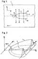
- Fig. 1the top view of a glass sheet 1 is shown, which along the Line 2 (dividing line) is to be cut.
- the Glass pane 1On the surface of the Glass pane 1, which is moved in the direction of the arrow (feed direction), turns on Directed heat radiation spot 3, which has a U-shaped contour.
- the Areas of increased radiation intensityare through the U-shaped curve 4 marked, which opens in the feed direction.
- the shape of the Heat radiation spotscorrespond approximately to half an ellipse, the widest of which Area forms the front end of the heat radiation spot 3.
- the two legs 18, 19 of the U-shaped curve 4are spaced and symmetrical to the dividing line 2.
- the distance between the legs 18, 19is in front area of the heat radiation spot 3 about 1 mm.
- the distance of the two legs 18, 19decreases to the vertex 16, which on the Dividing line 2 lies.
- the intensity distribution of the thermal radiation spot 3is the intensity distribution of the thermal radiation spot 3 represented in three dimensions. It can be seen that the ridge line of the Intensity maxima drops to the apex 16, where the local maximum 17 is located with respect to the dividing line 2. Inside the heat radiation spot the intensity is significantly lower. The height of the local maximum 17 must set according to the workpiece thickness and the cutting speed will. At high cutting or feed speeds, the local Maximum 17 be higher than at a lower feed speed. Here, the local maximum 17 must also be at the level of Radiation intensity can be adjusted in the front area of curve 4.
- the local maximum with respect to the dividing linedoes not have to be that at the same time Form the minimum of curve 4. If, for example, a laser without Power control is used, the intensity can be at vertex 16 show a slight increase.
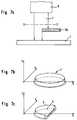
- a laser 6is provided as the heat radiation source, in particular a CO 2 laser, which emits a laser beam 7.
- This laser beam 7strikes a first mirror 8 oscillating about a vertical axis, which moves the beam 7 back and forth in a plane parallel to the surface of the glass pane 1.
- This oscillating laser beamstrikes a second mirror 9 oscillating about a horizontal axis, which moves the reflected laser beam back and forth in the X direction.
- the arrangement of the mirrors 8 and 9can also be interchanged.
- the laser beamDue to the superposition of the two oscillating movements, the laser beam describes the desired U-shaped curve 4 on the workpiece surface.
- a common control and Control device 11is provided, which is connected to the drives, not shown, of the two mirrors 8, 9 via the control lines 10a, 10b.
- the mirrors 8 and 9can also be controlled so that the laser beam is on the workpiece would go through a closed curve. To a U or To get a V-shaped curve, the laser is turned on or off accordingly switched off.
- the cooling spot 5is shown is generated by the cooling gas emerging from a spray nozzle 12.
- This Spray nozzleis connected to a supply unit 13.
- V-shaped curve 4shows a workpiece 1, on the surface of which a Thermal radiation spot 3 is directed with a triangular shape.
- the Areas of increased intensityare identified by the V-shaped curve 4.
- This V-shaped curve 4is also arranged symmetrically to the dividing line 2, so that the vertex 16 lies on the dividing line 2.
- a laser 6is provided which has a laser beam 7 sends out, which meets a mirror wheel 14.
- the surface of the mirror wheel 14is not cylindrical, but curved, so that during a Rotation of the mirror wheel 14 on the workpiece surface at least once the V-shaped curve 4 is traversed.
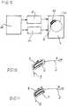
- FIG. 7aAn arrangement is sketched in FIG. 7a, in which a laser 6 is used is generated, which generates a laser beam 7 with TEM 01 * mode. Between Laser beam 6 and workpiece 1, an aperture 20 is arranged, the half of beam 7 fades out. The corresponding intensity profiles in front and behind the aperture are in the figures 7b and 7c.
- the methodproved to be suitable for completely separating glass up to a thickness of 1.1 mm, which could not be demonstrated with the methods according to the prior art.
- the powers of the CO 2 laser beam usedwere between 12 watts and 80 watts.
- the heat radiation spothad a length of typically 12 mm in the feed direction with a width of 1 mm.
- the cut edgesshowed no micro cracks, shells and splinters. In the case of thicker glasses above 0.7 mm thick, an almost vertical depth crack occurred down to a depth of a few hundred micrometers, which could also not be achieved with the other methods described above.
- V- or U-shapedshould not be understood to the letter will. Similar curves, e.g. a parabola, be used. Also, in the case of a V-shaped spot 3 according to FIG. 6 the legs 4 do not necessarily end at the apex. As shown in Fig. 8 shown, also extended beyond the apex leg 4 a have, in the partial figure 8 A the V-leg 4 and their Extensions 4 a are the same length and thus a quasi X-shaped spot form, and in the partial figure 8 B the elongated legs 4 a shorter than the actual V-legs are.
- the spot according to FIG. 8 Bcould also be reversed (shorter leg on the left).
- the glasswould be heated too quickly, i.e. of the local temperature gradient would be very high, causing damage to the Glases can lead. Since the heat "has no time" to enter the glass, the glass transition temperature Tg would be exceeded for a short time. The consequence would either be an uncontrolled break or a chipping of Surface particles.
- the laser beam spot according to FIG. 8 A - and analogously the spot according to FIG. 8 B -preferably have an intensity and temperature profile according to the Representation in FIG. 8 C with a maximum temperature at point M.
- the legs 4 and 4 a in FIGS. 8 A and 8 Bare, as shown, preferably linear. In principle, however, they can also be slightly curved.
- the width of the Heat radiation spotsare typically significantly shorter than their length. It is essential for an acceptable cut, as explained, that related the surface points in the cutting zone on the glass surface experience a specific course of heating and cooling over time have to. The consequence of this is that when the Cutting speed does not change the width of the radiation beam remains, but the length of the radiation beam must increase. Height Cutting speeds required for a high cutting throughput of a plant are necessary, therefore require a long, narrow heat radiation spot along the cutting line. Typical lengths of the heat radiation beam are 10 mm to 50 mm with a width of 0.5 mm to 2 mm with which Tendency towards small widths with high precision.
- the cuttingis with an elongated one In this respect, heat radiation spot without problems.
- cuts with a any given contourare also called Free-form cuts or contour cuts.
- Such contour cutsare used, for example, in the Cutting automotive glazing for windows and rearview mirrors as well for making larger holes in flat glass panes.
- the heat radiation beam of the webWhen cutting curves, the heat radiation beam of the web must be adjust the curved cut so that a maximum mechanical Tension arises in the glass to be cut and the width of the Heat input remains narrow.
- a linear heat radiation beamare thus when cutting curves with an elongated Heat radiation bundle only small radii of curvature of the cuts possible. With larger radii of curvature of the curves then only one shorter length of the linear heat radiation beam can be worked. The latter, however, only enables low cutting speeds.
- the twoare used to create the curved thermal radiation spots Scanner movements synchronized with each other so that one predominantly along the cutting line 2 oscillating movement of the Heat radiation beam is generated.
- the position of the Cooling 5 following the cutstill the local cutting position be adapted, for which purpose a mechanical rotating device is appropriate the scanner optics is provided.
- FIG. 9shows the in a schematic block diagram representation Overall arrangement of the device according to the invention, including the associated controls.
- Block 21identifies the scanner block including the controller 11 of FIG. 5 for generating the curved Heat radiation spot 22 on the circular cutting line 23 here on the Workpiece 1 with the trailing cooling point 5.
- the stage 24denotes a path control of the cutting process with a known structure.
- the blocks 21 and 24in terms of control technology coupled so that with free-form cuts with locally variable Cutting radii locally depending on the curvature of the cut with optimal Heat radiation bundles can be worked.
- the two-dimensional scanner device according to FIG. 6 with two vibrating deflecting mirrors 8.9can also be a two-dimensional one Scanner device can be used, within which regardless of the Cutting direction 2 (23) along one of the scanner axes 8 a, 9 a for oscillation the cutting direction 2 (23) is used, and the perpendicular to this Deflecting mirror the V or U or elliptical beam profile accordingly adapts to the local curvature of the cutting path.
- the Entire scanner devicecan be freely rotated mechanically by 360 °.
- Especially at 11has this scanner axis in the variant according to FIG.
- the most diverse devicescan be used by means of the devices described generate curved heat radiation bundles or cutting spots, of which in Figures 10 and 11 a curved U or V-shaped Heat radiation bundle is shown, the bundle being different Way is generated.
- the radiation beam or the associated one Heat radiation spot 4 generated in that the heat radiation beamdescribes closed curved path 1 on the surface of the glass.
- an oscillating movementLayered this oscillating movement in cutting direction A becomes a movement less deflection perpendicular to the cutting line 2.
- the heat radiation beamtherefore takes place to generate the heat radiation spot 4, such as shown, a closed curved path B, which envelops the cutting line 2.
- the performance of the Thermal radiation sourceis approximately reduced to zero, when the front scanner position in cutting direction A is reached.
- the U or V-shaped beam profileis thus controlled by the Heat radiation source generated. With a constant output power the source would be elliptical.
- the U or V-shaped beam profilecan also be created by an elliptical Beam profile is blinded.
- a radiation-absorbing diaphragm or the like in the beam pathpositioned.
- the curved U- or V-shaped 4 generated by the The heat radiation beamdoes not oscillate in a rotating path, but rather alternately on both sides of the cutting line 2 over a predetermined length with a reversing loop at the trailing starting point of the curve 4.
- the output of the heat radiation sourcemust be used to produce such a source No heat radiation spot with the specified intensity distribution must be controlled.
- the scanner frequency along the cutting line twice as high as perpendicular to Cutting line, which is characterized by moving the U or V-shaped profileresults.
Landscapes
- Physics & Mathematics (AREA)
- Optics & Photonics (AREA)
- Engineering & Computer Science (AREA)
- Plasma & Fusion (AREA)
- Mechanical Engineering (AREA)
- Chemical & Material Sciences (AREA)
- Materials Engineering (AREA)
- Organic Chemistry (AREA)
- Thermal Sciences (AREA)
- Toxicology (AREA)
- Health & Medical Sciences (AREA)
- Re-Forming, After-Treatment, Cutting And Transporting Of Glass Products (AREA)
- Laser Beam Processing (AREA)
- Perforating, Stamping-Out Or Severing By Means Other Than Cutting (AREA)
- Processing Of Stones Or Stones Resemblance Materials (AREA)
Abstract
Translated fromGermanDescription
Translated fromGermanDie Erfindung betrifft ein Verfahren zum Durchtrennen von flachenWerkstücken aus sprödem Material, insbesondere aus Glas gemäß demOberbegriff des Patentanspruchs 1. Die Erfindung bezieht sich auch auf eineVorrichtung gemäß dem Oberbegriff des Patentanspruchs 10.The invention relates to a method for cutting flatWorkpieces made of brittle material, especially glass according to thePreamble of
Konventionelle Verfahren zum Schneiden von Flachglas basieren darauf,mittels eines Diamanten oder eines Schneidrädchens zunächst eine Ritzspur imGlas zu generieren, um das Glas anschließend durch eine äußere mechanischeKraft entlang der so erzeugten Schwachstelle zu brechen. Nachteilig ist beidiesem Verfahren, daß durch die Ritzspur Partikel (Splitter) aus der Oberflächegelöst werden, die sich auf dem Glas ablagern können und dort beispielsweisezu Kratzern führen können. Ebenfalls können sogenannte Ausmuschelungen ander Schnittkante entstehen, die zu einem unebenen Glasrand führen und somiteinen erheblichen Nachbearbeitungsaufwand erfordern. Weiterhin führen diebeim Ritzen entstehenden Mikrorisse in der Schnittkante zu einer verringertenmechanischen Beanspruchbarkeit, d. h. zu einer erhöhten Bruchgefahr.Conventional processes for cutting flat glass are based onfirst use a diamond or a cutting wheel to scratch the trackGenerate glass to the glass subsequently by an external mechanicalForce to break along the weak point thus created. The disadvantage isthis process that through the scratch track particles (splinters) from the surfacesolved, which can be deposited on the glass and there for examplecan lead to scratches. So-called clams can also be usedthe cut edge arise, which lead to an uneven glass edge and thusrequire a considerable amount of post-processing. Furthermore, themicrocracks in the cutting edge that occur during scribing are reducedmechanical strength, d. H. to an increased risk of breakage.
Ein Ansatz, um sowohl Splitter als auch Ausmuschelungen und Mikrorisse zuvermeiden, besteht im Trennen von Glas auf der Basis thermisch generierterSpannung. Hierbei wird eine Wärmequelle, die auf das Glas gerichtet ist, mitfester Geschwindigkeit über das Glas bewegt und so eine derart hohethermische Spannung erzeugt, daß das Glas Risse bildet. Der notwendigen Eigenschaft der Wärmequelle, die thermische Energie lokal, d. h. mit einerGenauigkeit besser einen Millimeter, was den typischen Schnittgenauigkeitenentspricht, positionieren zu können, genügen Infrarotstrahler, spezielleGasbrenner und insbesondere Laser. Laser haben sich wegen ihrer gutenFokussierbarkeit, guten Steuerbarkeit der Leistung sowie der Möglichkeit derStrahlformung und damit der Intensitätsverteilung auf Glas bewährt unddurchgesetzt.An approach to both splinters and clams and micro cracksavoid, consists in separating glass on the basis of thermally generatedTension. This involves using a heat source that is directed towards the glassfixed speed over the glass and so highThermal stress creates cracks in the glass. The necessaryProperty of the heat source, the thermal energy locally, d. H. with aAccuracy better than a millimeter, which is the typical cutting accuracycorresponds to being able to position, infrared radiators are sufficient, specialGas burners and especially lasers. Lasers have become because of their goodFocusability, good controllability of the performance as well as the possibility ofBeam shaping and thus the intensity distribution on glass has proven itself andenforced.
Aus der DE-AS 1 244 346 ist ein Verfahren zum Ritzen von Glas bekannt, beidem entlang der Schnittbahn eine Erwärmung des Glases mittels einesLaserstrahls erzeugt wird, wobei eine Temperatur unterhalb derSchmelztemperatur des Glases eingestellt wird. Im Anschluß an dieErwärmung wird das Glas gekühlt und durch Klopfen oder Biegen abgetrennt.Es kann auch eine Erwärmung über die Schmelztemperatur herbeigeführtwerden, so daß ein feiner Spalt herausgeschmolzen wird.From DE-AS 1 244 346 a method for scribing glass is known fromwhich along the cutting path is heated by a glassLaser beam is generated, a temperature below thatMelting temperature of the glass is set. Subsequent toWhen heated, the glass is cooled and tapped or bent to separate it.It can also bring about heating above the melting temperaturebe so that a fine gap is melted out.
Die GB-PS 1,433,563 beschreibt ein Verfahren, bei dem mit zweiLaserstrahlen gearbeitet wird, wobei ein Strahl mit niedrigerer Energie zumVorwärmen eingesetzt wird.GB-PS 1,433,563 describes a method in which twoLaser beams are worked, using a beam with lower energy forPreheating is used.
In der DE 4 411 037 C2 wird ein Verfahren beschrieben, bei dem in einHohlglas mittels eines Laserstrahls eine umlaufende Spannungszone mit einerTemperatur von 250°C eingebracht wird. Nach dem Einbringen derSpannungszone wird mit einer Anrißspitze durch kurzzeitigen Kontakt mit derOberfläche des Hohlglases mechanisch ein kurzer Startriß eingebracht, der imwesentlichen auf die Spur der maximalen Intensität des Laserstrahls und damitder höchsten Temperatur gesetzt wird. Die Spannungszone wird mittels einesflüssigkeitsgetränkten Vlieses gekühlt, wodurch der Thermoschock und damitdie Spannungen so erhöht werden, daß sich der Startriß zu einem Trennrißausbildet.DE 4 411 037 C2 describes a method in which aHollow glass by means of a laser beamTemperature of 250 ° C is introduced. After inserting theTension zone is created with a tip by brief contact with theMechanically introduced a short start crack on the surface of the hollow glassessentially on the track of the maximum intensity of the laser beam and thusthe highest temperature is set. The tension zone is determined by means of aliquid-soaked fleece cooled, causing the thermal shock and thusthe tensions are increased so that the starting crack becomes a separation cracktrains.
Die US 5,237,150, beschreibt ein Schneidverfahren für dicke Stahlplatten, daseinen Laserstrahl im Ringmodus benutzt, um die Fokussierlinse zu schonen.Beim Auftreffen auf die Linse ist der Laserstrahl ringförmig, so daß sich dieEnergie des Laserstrahls über eine größere Fläche der Linse verteilt als beieinem punktförmigen Auftreffen. Dadurch wird eine lokale Überhitzung desLinsenmaterials vermieden. Auf dem Werkstück selbst wird der Strahl jedochmittels der Fokussierlinse zu einem Punkt fokussiert. In diesem Punkt-Fleck istkeine erhöhte Intensität im Randbereich wie bei einem ringförmigen Fleckvorhanden, da der ringförmige Strahl zu einem "Punkt" geworden ist, der als"schneidender Punkt" den Stahl längs der Trennlinie aufschneidet.US 5,237,150 describes a cutting method for thick steel plates, theuses a laser beam in ring mode to protect the focusing lens.When hitting the lens, the laser beam is ring-shaped, so that theEnergy of the laser beam distributed over a larger area of the lens than ina punctiform impact. This will cause local overheating of theAvoided lens material. However, the beam is on the workpiece itselffocused to a point using the focusing lens. In this point stain isno increased intensity in the edge area as with an annular spotexists because the annular beam has become a "point" which is called"intersecting point" cuts the steel along the dividing line.
Bei dem Verfahren nach der EP 0 062 484, wird ebenfalls ein Laserstrahl imRingmodus TEMo benutzt, der punktförmig auf das Werkstück fokussiert wird.Wenn der Laserstrahl aber punktförmig fokussiert wird, werden dieIntensitätsmaxima zu einem Punkt verschmelzen.
Dadurch, daß der Laserstahl auf der Oberfläche des Werkstückes fokussiertwird, verdampft das Glas bis zu einer bestimmten Tiefe. Das restliche Glas imTrennbereich wird über den Schmelzpunkt hinaus erhitzt. Mittels eines Gaseswird das verdampfte Glasmaterial entfernt.In the method according to
Because the laser steel is focused on the surface of the workpiece, the glass evaporates to a certain depth. The remaining glass in the separation area is heated above the melting point. The vaporized glass material is removed by means of a gas.
Die DE-OS 43 05 107 betrifft ein Verfahren und eine Vorrichtung zumSchneiden von Glas mit Laserstahlung, wobei der Laserstrahl in zwei paralleleStrahlen geteilt wird, mit denen das Glas symmetrisch zur Trennlinie beaufschlagtwird. Mit einer solchen Anordnung kann kein exakter Schritt (± 0,1mm) erzeugt werden, sondern der Riß pendelt zwischen den beidenStrahllinien.DE-OS 43 05 107 relates to a method and an apparatus forCutting glass with laser radiation, with the laser beam in two parallelBeams is shared with which the glass is applied symmetrically to the dividing linebecomes. With such an arrangement, an exact step (± 0.1mm) are generated, but the crack oscillates between the twoRay lines.
Das aus der WO 93/20015 bekannte Verfahren nutzt einen Laserstrahl mitelliptischer Form. Dieses Verfahren zeigt gute Ergebnisse beim gradlinigenRitzen von nichtmetallischem Plattenmaterial, kann jedoch kein hochwertigesund hochpräzises Ritzen entlang einer gekrümmten Kontur sichern. Zudem weist das genannte Verfahren eine geringe Stabilität des Schneidablaufs beieiner hohen Strahlungsdichte und hohen Schnittgeschwindigkeiten auf.Dies hängt damit zusammen, daß die Erhitzung mit einem Laserbündel mitelliptischem Querschnitt und der Gaußschen Verteilung der Strahlungsdichte ineinem sehr engen Bereich erfolgt, wobei sich die Temperatur von derPeripherie zum Zentrum gravierend erhöht. Es ist extrem kompliziert, einstabiles Thermospalten bei hoher Geschwindigkeit, hoher Ritztiefe unddennoch auch eine stabile Leistungsdichte zu erzielen, wenn die Erhitzung desWerkstoffes häufig mit dessen Überhitzung im zentralen Bereich desBestrahlungsbereiches einhergeht, d. h. die Aufweichtemperatur des Materialsüberschritten wird, obwohl dies bei hochwertigem Schneiden unzulässig ist.The method known from WO 93/20015 also uses a laser beamelliptical shape. This method shows good results in straight linesScoring of non-metallic plate material, however, can not be a high qualityand high-precision scratching along a curved contour. In additionthe method mentioned has a low stability of the cutting processa high radiation density and high cutting speeds.This is due to the fact that the heating with a laser beamelliptical cross section and the Gaussian distribution of the radiation density intakes place in a very narrow range, the temperature of whichPeriphery to the center increased significantly. It is extremely complicatedstable thermal splitting at high speed, high scratch depth andto achieve a stable power density when heating theOften with its overheating in the central area of the materialIrradiation area, d. H. the softening temperature of the materialis exceeded, although this is not permitted with high-quality cutting.
Die WO 96/20062 als nächstkommender Stand der Technik beschreibt einVerfahren zum Durchtrennen von flachen Werkstücken aus sprödem Material,insbesondere aus Glas, längs einer vorgegebenen Trennlinie mit einem zu ihrsymmetrischen Wärmestrahlungsfleck, der eine erhöhte Strahlungsintensität inseinem Randbereich mit einem Temperaturmaximum an seinem hinteren Endebesitzt, wobei der Wärmestrahlungsfleck längs der Trennlinie und/oder dasWerkstuck bewegt wird, und bei dem der erwärmte Trennlinienabschnittanschließend gekühlt wird. Diese Merkmale bilden den Oberbegriff desAnspruchs 1.WO 96/20062 as the closest prior art describes aProcess for cutting flat workpieces made of brittle material,in particular made of glass, along a predetermined dividing line with one to itsymmetrical heat radiation spot, which has an increased radiation intensity inits edge area with a temperature maximum at its rear endhas, the heat radiation spot along the dividing line and / orWorkpiece is moved, and in which the heated dividing line sectionis then cooled. These characteristics form the generic term of
Im bekannten Fall ist ein ovaler oder elliptischer Wärmestrahlungsfleckvorgesehen, mit einem Strahlungsintensitätsminimum innerhalb des Ovals. Einsolcher "Schneidfleck" schneidet die Trennlinie zweimal, nämlich am vorderenund am hinteren Ende des Ovals. Dadurch ergibt sich mit Nachteil eineungünstige Temperaturverteilung, die in Figur 1 der WO-Schrift dargestellt.ist. Durch den vorlaufenden Schnittpunkt findet bereits im vorderen Bereichdes elliptischen Schneidflecks in Schneidrichtung gesehen im Bereich derTrennlinie eine unnötige Aufheizung statt.In the known case there is an oval or elliptical thermal radiation spotprovided, with a radiation intensity minimum within the oval. Asuch a "cutting spot" cuts the dividing line twice, namely at the frontand at the back of the oval. This results in a disadvantageunfavorable temperature distribution shown in Figure 1 of the WO document.is. Due to the leading intersection already takes place in the front areaof the elliptical cutting spot in the cutting direction in the area ofDividing line an unnecessary heating instead.
Hierdurch entsteht in der Mitte des Schneidfleckes, d.h. auf der Trennlinie,eine unnötig große Aufheizung, so daß am Ende des Brennfleckes, wo dieStrahlungsintensität wiederum im Bereich der Trennlinie sehr groß wird unddie Temperatur ein Maximum erreicht, das Glas unter Umständen schonaufschmelzen kann.This creates in the middle of the cutting spot, i.e. on the dividing line,an unnecessarily large heating, so that at the end of the focal spot where theRadiation intensity in turn becomes very large in the area of the dividing line andthe temperature has reached a maximum, but the glass may havecan melt.
Mit diesem Verfahren können ferner nur Gläser mit einer Stärke bistypischerweise 0,2 Millimeter durchtrennt werden, weil bei höherennotwendigen Strahlleistungen ansonsten ein Aufschmilzen stattfindet und derRiß unterbricht. Bei größeren Glasdicken findet nur ein Ritzen des Glases statt.With this method only glasses with a thickness up totypically cut 0.2 millimeters because at highernecessary beam power otherwise melting takes place and theCrack breaks. With larger glass thicknesses, the glass is only scratched.
Aufgabe der vorliegenden Erfindung ist es, ein Verfahren und eineVorrichtung bereitzustellen, mit dem flache Werkstücke, insbesondere mitgrößerer Dicke, z. B. Glasscheiben mit einer Dicke größer 0,2 Millimeter,durchtrennt werden können, ohne daß Mikrorisse, Ausmuschelungen oderSplitter auftreten. Weiter soll bei dicken Gläsern eine Ritztiefe erzielt werden,die größer als die mit anderen Verfahren erzielbare Ritztiefe ist.The object of the present invention is a method and aTo provide a device with which flat workpieces, in particular withgreater thickness, e.g. B. glass panes with a thickness greater than 0.2 millimeters,can be cut without micro cracks, mussels orSplinters occur. Furthermore, a scratch depth should be achieved with thick glasses,which is greater than the scratch depth that can be achieved with other methods.
Diese Aufgabe wird mit einem Verfahren gemäß dem Patentanspruch 1 gelöst.This object is achieved with a method according to
Durch die Maßnahmen nach Anspruch 1 wird erst zum Ende derWärmebehandlung auf der Trennlinie Energie eingebracht und damit dort einehohe Temperatur im Werkstück erreicht. Es wird dadurch eine hohemechanische Spannung mit einem lokalen Temperaturmaximum auf derTrennlinie erzeugt. Bei nachfolgender Kühlung auf der Trennlinie undvorheriger Schwächung des Glases am Startpunkt des Schnittes reißt das Glasentlang des Vorschubes auf der Trennlinie. Wegen des starken lokalenTemperaturmaximums auf der Trennlinie folgt der Schnitt sehr präzise derTrennlinie, was beispielsweise bei Präzisionsschnitten in der Displayindustrienotwendig ist.By the measures according to
Ein weiterer Vorteil des erfindungsgemäßen Verfahrens besteht darin, daß einmechanisches Brechen nach der Wärme- und Kühlbehandlung nicht notwendigist, so daß saubere Trennkanten erzielt werden.Another advantage of the method according to the invention is that amechanical breaking after the heat and cooling treatment is not necessaryis so that clean separating edges are achieved.
Bei dem erfindungsgemäß geformten Wärmestrahlungsfleck mit der V- oder U-förmigenKontur liegen die Bereiche des Wärmestrahlungsflecks mit erhöhterStrahlungsintensität daher auf einer V- oder U-förmigen Kurve, die sich inSchneidrichtung öffnet. Die beiden Schenkel der V- bzw. U-förmigen Kurveliegen gleich beabstandet benachbart der Trennlinie, so daß bei einer derartigenGestalt des Wärmestrahlungsflecks die Werkstückoberfläche durch die beidenbeabstandeten Intensitätsmaxima zunächst auf einer großen Breite, die bis zueinigen Millimetern betragen kann, aufgeheizt wird, wobei zwischen beidenIntensitätsmaxima zunächst ein lokales Temperaturminimum besteht. Durch dasZusammenlaufen der Schenkel der V- bzw. U-förmigen Kurve am hinterenEnde des Wärmestrahlungsflecks in den Scheitelpunkt wird das lokaleTemperaturminimum zunehmend verringert, d.h. die Temperatur im Bereichder Trennlinie nimmt zum Ende des Wärmestrahlungsflecks hin zu und erreichtdort ein lokales Temperaturmaximum, insbesondere an derWerkstückoberfläche, das aber noch unterhalb der Schmelztemperatur desWerkstücks liegt. Ein derartiger Wärmestrahlungsfleck bewirkt, daß imBereich des Abstandes der Intensitätsmaxima eine homogene Aufheizung desWerkstückes auf großer Breite und auch in der Tiefe auf eine Temperaturunterhalb der Schmelztemperatur erreicht wird, was bei einem Strahl mit einermaximalen Intensität im Zentrum, insbesondere am Anfang desWärmestrählungsflecks, nicht der Fall ist. Der so erzeugten Aufheizspur folgteine unmittelbare Kühlung mittels einer Flüssigkeit, eines Gases oder einesunterkühlten mechanischen Tastkopfes, die auf der Trennlinie die größteIntensität hat. Diese Kühlung bewirkt eine Kontraktion des Materials. Durchdie Aufheizung auf großer Breite mit einem Temperaturmaximum auf derTrennlinie wird in Kombination mit der Kühlung, die ebenfalls auf derTrennlinie ihre größte Wirkung zeigt, eine vergleichsweise hohe mechanische Spannung mit einem starken lokalen Maximum auf der Trennlinie erzeugt.Dadurch ist es möglich, auch große Werkstückdicken sauber zu durchtrennen.In Versuchen konnte gezeigt werden, daß Glasscheiben mit einer Dicke bis zu1,1 mm stabil durchtrennt werden können.In the case of the heat radiation spot shaped according to the invention with the V-shaped or U-shapedContour the areas of the heat radiation spot with increasedRadiation intensity therefore on a V or U-shaped curve, which is inCutting direction opens. The two legs of the V- or U-shaped curveare equally spaced adjacent to the dividing line, so that in such aShape the heat radiation spot the workpiece surface through the twospaced intensity maxima initially over a large width, up toa few millimeters, is heated, being between the twoIntensity maxima initially there is a local temperature minimum. By theThe legs of the V- or U-shaped curve converge at the rearThe end of the heat radiation spot in the apex becomes the local oneTemperature minimum increasingly reduced, i.e. the temperature in the areathe dividing line increases towards the end of the heat radiation spot and reaches itthere a local temperature maximum, especially at theWorkpiece surface, which is still below the melting temperature of theWorkpiece lies. Such a heat radiation spot causes that inRange of the distance of the intensity maxima a homogeneous heating of theWorkpiece over a wide width and also at depth to a temperaturebelow the melting temperature, which is the case with a jet with amaximum intensity in the center, especially at the beginning of theHeat radiation spots, not the case. The heating trace thus generated followsdirect cooling by means of a liquid, a gas or asupercooled mechanical probe, the largest on the dividing lineIntensity. This cooling causes a contraction of the material. Byheating over a large width with a maximum temperature on theSeparation line is used in combination with the cooling, which is also on theTrennlinie shows its greatest effect, a comparatively high mechanicalVoltage with a strong local maximum is generated on the dividing line.This makes it possible to cut even large workpiece thicknesses cleanly.Experiments have shown that glass panes with a thickness of up to1.1 mm can be cut stably.
Die Breite des V- oder U-förmigen Wärmestrahlungsflecks liegt vorzugsweisebei 0,5 bis 2 mm. Die Länge des Wärmestrahlungsflecks kann 10 bis 30 mmbetragen. Bei der Einstellung dieser Werte sind im Hinblick auf eine homogeneErwärmung in der Tiefe des Werkstücks u.a. die Vorschubgeschwindigkeit.Werkstücksdicke, Strahlungsintensität und die Materialeigenschaften zuberücksichtigen.The width of the V- or U-shaped thermal radiation spot is preferablyat 0.5 to 2 mm. The length of the heat radiation spot can be 10 to 30 mmbe. When setting these values are with regard to a homogeneousHeating in the depth of the workpiece etc. the feed rate.Workpiece thickness, radiation intensity and the material properties tooconsider.
Gemäß einer besonderen Ausführungsform wird der Wärmestrahlungsfleckdurch Scannen eines Laserstrahls erzeugt.According to a special embodiment, the thermal radiation spotgenerated by scanning a laser beam.
Vorzugsweise wird das Scannen in Form einer Ellipse durchgeführt, wobei derLaser zur Erzeugung einer V- oder U-förmigen Kurve abwechselnd ein- undausgeschaltet oder der Strahl ein- und ausgeblendet wird.The scanning is preferably carried out in the form of an ellipse, theLasers for generating a V or U-shaped curve alternately on andswitched off or the beam is faded in and out.
Hinsichtlich der Vorrichtung zum Durchtrennen von flachen Werkstücken aussprödem Material, insbesondere aus Glas, längs einer vorgegebenenTrennlinie,
- mit einer optischen Einrichtung, die eine Wärmestrahlungsquelle,insbesondere einen Laser, und mindestens eine optische Komponenteumfaßt zur Erzeugung eines zur Trennlinie symmetrischenWärmestrahlungsfleckes, der eine erhöhte Strahlungsintensität in seinemRandbereich mit einem Temperaturmaximum an seinem hinteren Endebesitzt,
- mit einer Einrichtung zum Bewegen des zu durchtrennendenWerkstücks und/oder des Wärmestrahlungsflecks längs der Trennlinie,und
- mit einer Kühleinrichtung zum Kühlen des bestrahltenTrennlinienabschnitts,
- with an optical device which comprises a heat radiation source, in particular a laser, and at least one optical component for generating a heat radiation spot which is symmetrical with respect to the dividing line and which has an increased radiation intensity in its edge region with a temperature maximum at its rear end,
- with a device for moving the workpiece to be cut and / or the heat radiation spot along the dividing line, and
- with a cooling device for cooling the irradiated dividing line section,
Gemäß einer ersten Ausführungsform kann eine Scannereinrichtung verwendetwerden. Dementsprechend weist die optische Einrichtung zwei senkrechtzueinander angeordnete, oszillierende, synchronisierte Spiegel auf, die einenLaserstrahl auf die Oberfläche des Werkstücks derart lenken, wo er dort eineV- oder U-förmige Kurve beschreibt.According to a first embodiment, a scanner device can be usedwill. Accordingly, the optical device has two perpendicularmutually arranged, oscillating, synchronized mirrors on the oneDirect the laser beam onto the surface of the workpiece in such a way that there is aV- or U-shaped curve describes.
Um die Synchronisation der beiden Spiegel zu realisieren, sind dieAntriebseinrichtungen der beiden oszillierenden Spiegel an eine gemeinsameSteuer- und Regeleinrichtung angeschlossen. Vorzugsweise liegt dieOszillationsfrequenz der beiden Spiegel bei 500 bis 2000 Hz, so daß eineSchneidgeschwindigkeit von 50 mm/sec bis 1000 mm/sec erreicht werdenkann, was von der eingesetzten Strahlungsintensität abhängt.In order to realize the synchronization of the two mirrors, they areDrive devices of the two oscillating mirrors to a common oneControl and regulating device connected. Preferably, theOscillation frequency of the two mirrors at 500 to 2000 Hz, so that oneCutting speeds of 50 mm / sec to 1000 mm / sec can be achievedcan do what depends on the radiation intensity used.
Gemäß einer weiteren Ausführungsform einer Scannereinrichtung weist dieoptische Einrichtung ein Spiegelrad auf, dessen Oberfläche derart gekrümmtist, daß ein darauf reflektierter Laserstrahl während einer Rotation des Spiegelrades mindestens einmal eine U- oder V-förmige Kurve auf derOberfläche des zu duchtrennenden Werkstückes beschreibt.According to a further embodiment of a scanner device, theoptical device on a mirror wheel, the surface of which is curved in this wayis that a laser beam reflected thereon during a rotation of theSpiegelrades at least once a U or V-shaped curve on theDescribes the surface of the workpiece to be cut.
Die Rotationsfrequenz des Spiegelrades liegt bei 500 bis 3000 Hz, so daß diegenannten Vorschubgeschwindigkeiten erreicht werden können.The rotation frequency of the mirror wheel is 500 to 3000 Hz, so that thementioned feed speeds can be achieved.
Vorzugsweise wird ein Laser mit einer Wellenlänge eingesetzt, die in demMaterial eine große Absorption erfährt. Beispielsweise wird für Glas ein CO2-Laserverwendet, der mit einer Wellenlänge von 10,6 µm ausgestattet ist undkommerziell günstig zu erhalten ist. Die maximale Ausgangsleistung desLasers beträgt typischerweise 150 Watt.A laser with a wavelength that is highly absorbed in the material is preferably used. For example, a CO2 laser is used for glass, which is equipped with a wavelength of 10.6 µm and is commercially available. The maximum output power of the laser is typically 150 watts.
Die Intensität des Lasers ist vorzugsweise während jedes Durchlaufs der V- oderU-förmigen Kurve veränderbar, so daß im Bereich des Scheitelpunktesder V- oder U-förmigen Kurve die Strahlungsintensität variiert werden kann.Die Strahlungsintensität wird vorzugsweise so eingestellt, daß dieSchmelztemperatur des Werkstücks nicht überschritten wird.The intensity of the laser is preferably the V or during each passU-shaped curve changeable so that in the area of the apexthe V- or U-shaped curve the radiation intensity can be varied.The radiation intensity is preferably set so that theMelting temperature of the workpiece is not exceeded.
Eine Steuerung der Scannerbewegung, die den Scanner bei Kreisschnitten undFreiformschnitten so steuert, daß eine der Kurvenbahn angepaßte, gekrümmteV- oder U-förmige Intensitätsverteilung entsteht, ist ebenfalls möglich, wiespäter noch anhand der Figurenbeschreibung erläutert werden wird.A control of the scanner movement, the scanner with circular cuts andControls free-form cuts in such a way that a curved curve is adapted to the curved pathV- or U-shaped intensity distribution is also possible, likewill be explained later with reference to the figure description.
Anstelle dieser Scannereinrichtungen kann die gewünschte Form desWärmestrahlungsflecks auch durch strahlformende Optiken erreicht werden.Instead of these scanner devices, the desired form of theHeat radiation spots can also be achieved by beam-shaping optics.
Eine weitere Möglichkeit besteht darin, eine Wärmestrahlungsquelle in Formeines Lasers mit einem TEM 01*-Mode zu verwenden, wobei die optischeEinrichtung eine entsprechende Blende umfaßt, die einen Teil des Strahlsderart ausblendet, daß die erhöhte Strahlungsintensität im Bereich der Werkstückoberfläche auf einer V- oder U-förmigen Kurve liegt. Ein TEM 01*-Modewird erzeugt durch einen speziellen Resonatoraufbau eines CO2-Lasers.Another possibility is to use a heat radiation source in the form of a laser with a TEM 01 * mode, the optical device comprising a corresponding diaphragm which blocks part of the beam in such a way that the increased radiation intensity in the region of the workpiece surface on a V - or U-shaped curve. A TEM 01 * mode is generated by a special resonator structure of a CO2 laser.
Bezüglich der Kühleinrichtung kann beispielsweise ein unterkühltermetallischer Tastkopf verwendet werden. Ferner besteht die Möglichkeit, alsKühleinrichtung eine Gasstrahleinrichtung, eineFlüssigkeitsinjektionseinrichtung oder eine Flüssigkeitszerstäubungseinrichtungzu verwenden.With regard to the cooling device, for example, a subcooled onemetallic probe can be used. There is also the option ofCooling device, a gas jet device, aLiquid injection device or a liquid atomization deviceto use.
Beispielhafte Ausführungsformen der Erfindung werden nachfolgend anhandder Zeichnungen näher erläutert.Exemplary embodiments of the invention are described belowthe drawings explained in more detail.
Es zeigen:
- Fig. 1
- die Draufsicht auf einen Ausschnitt auf ein zu durchtrennendesWerkstück,
- Fig. 2
- eine dreidimensionale Darstellung des Intensitätsverlaufs einesWärmestrahlungsflecks,
- Fig. 3
- Schnitte durch das Intensitätsprofil bzw. Temperaturprofil durchden in Fig. 1 gezeigten Wärmestrahlungsfleck längs der LinienA-A', B-B' und C-C',
- Fig. 4
- eine graphische Darstellung des Temperaturverlaufs längs derTrennlinie,
- Fig. 5
- eine perspektivische Darstellung einer optischen und einerKühleinrichtung,
- Fig. 6
- eine perspektivische Darstellung einer weiteren Ausführungsformder erfindungsgemäßen Vorrichtung,
- Fig.7a-c
- Darstellungen einer weiteren Ausführungsform dererfindungsgemäßen Vorrichtung mit Intensitätsprofilen,
- Fig. 8 A-C
- einen V-förmigen Wärmestrahlungsfleck mit verlängertenSchenkeln über den Scheitelpunkt hinaus, sowie die zugehörigeTemperaturverteilung,
- Fig. 9
- eine schematische Blockschaltbild-Darstellung für dieGesamtanordnung der erfindungsgemäßen Vorrichtuungeinschließlich der zugehörigen Steuerungen, die auchFreiformschnitte mit gekrümmten Wärmestrahlungsfleckenermöglicht,
- Fig. 10
- ein zweidimensional durch Scannen entlang der Schnieidlinie,benachbart zu dieser geführtes Wärmestrahlungsbündel miteinem U- oder V-förmig langgestreckten, entsprechend derKrümmung der Schneidlinie, diese einhüllend, gekrümmtenWärmestrahlungsfleck, der durch eine umlaufendeScannerbewegung erzeugt wird, und
- Fig. 11
- ein Wärmestrahlungsfleck entsprechend Fig. 10, der jedochdurch eine reversierende Scannerbewegung erzeugt wird.
- Fig. 1
- the top view of a section of a workpiece to be cut,
- Fig. 2
- a three-dimensional representation of the intensity profile of a thermal radiation spot,
- Fig. 3
- Sections through the intensity profile or temperature profile through the heat radiation spot shown in FIG. 1 along the lines A-A ', BB' and C-C ',
- Fig. 4
- a graphical representation of the temperature curve along the dividing line,
- Fig. 5
- a perspective view of an optical and a cooling device,
- Fig. 6
- 2 shows a perspective illustration of a further embodiment of the device according to the invention,
- Fig.7a-c
- Representations of a further embodiment of the device according to the invention with intensity profiles,
- Fig. 8 AC
- a V-shaped heat radiation spot with extended legs beyond the apex, as well as the associated temperature distribution,
- Fig. 9
- 2 shows a schematic block diagram representation for the overall arrangement of the device according to the invention, including the associated controls, which also enables free-form cuts with curved heat radiation spots,
- Fig. 10
- a two-dimensionally by scanning along the cutting line, adjacent to this guided heat radiation bundle with a U- or V-shaped elongated, corresponding to the curvature of the cutting line, enveloping this, curved heat radiation spot, which is generated by a circumferential scanner movement, and
- Fig. 11
- a heat radiation spot according to FIG. 10, which is, however, generated by a reversing scanner movement.
In der Fig. 1 ist die Draufsicht auf eine Glasscheibe 1 dargestellt, die längs derLinie 2 (Trennlinie) durchtrennt werden soll. Auf die Oberfläche derGlasscheibe 1, die in Pfeilrichtung (Vorschubrichtung) bewegt wird, wird einWärmestrahlungsfleck 3 gerichtet, der eine U-förmige Kontur aufweist. DieBereiche erhöhter Strahlungsintensität sind durch die U-förmige Kurve 4 gekennzeichnet, die sich in Vorschubrichtung öffnet. Die Gestalt desWärmestrahlungsflecks entspricht in etwa einer halben Ellipse, deren breitesterBereich das vordere Ende des Wärmestrahlungsflecks 3 bildet.In Fig. 1 the top view of a
Die beiden Schenkel 18, 19 der U-förmigen Kurve 4 liegen beabstandet undsymmetrisch zur Trennlinie 2. Der Abstand der Schenkel 18, 19 beträgt imvorderen Bereich des Wärmestrahlungsflecks 3 etwa 1 mm. Der Abstand derbeiden Schenkel 18, 19 verringert sich zum Scheitelpunkt 16, der auf derTrennlinie 2 liegt.The two
In der Fig. 2 ist die Intensitätsverteilung des Wärmestrahlungsflecks 3dreidimensional dargestellt. Es ist zu sehen, daß die Kammlinie derIntensitätsmaxima zum Scheitelpunkt 16 abfällt, wo sich das lokale Maximum17 bezüglich der Trennlinie 2 befindet. Im Inneren des Wärmestrahlungsflecksist die Intensität deutlich geringer. Die Höhe des lokalen Maximums 17 mußentsprechend der Werkstückdicke und der Schneidgeschwindigkeit eingestelltwerden. Bei hoher Schneid- oder Vorschubgeschwindigkeit muß das lokaleMaximum 17 höher sein als bei einer geringeren Vorschubgeschwindigkeit.Hierbei muß das lokale Maximum 17 auch auf die Höhe derStrahlungsintensität im vorderen Bereich der Kurve 4 abgestimmt werden.2 is the intensity distribution of the
Das lokale Maximum bezüglich der Trennlinie muß nicht gleichzeitig dasMinimum der Kurve 4 bilden. Wenn beispielsweise ein Laser ohneLeistungssteuerung verwendet wird, kann im Scheitelpunkt 16 die Intensitäteine leichte Überhöhung aufweisen.The local maximum with respect to the dividing line does not have to be that at the same timeForm the minimum of
In der Fig. 3 sind drei Schnitte durch das Intensitätsprofil längs der Linie A-A',B-B' und C-C' (siehe Fig. 1) dargestellt. Man sieht, daß derKurvenverlauf, der durch den Schnitt C-C' gekennzeichnet ist, zweibeabstandete Maxima aufweist, die deutlich höher sind, als die beidenbeabstandeten Maxima beim Schnitt B-B'. Im Scheitelpunkt 16, der durch den Schnitt A-A' gekennzeichnet ist, ist das Intensitätsmaximum noch einmaldeutlich niedriger. Dadurch, daß durch die beiden Maxima eine Vorerwärmungin einem breiten Bereich um die Trennlinie eine Art Vorerwärmungstattgefunden hat, zeigt das Temperaturprofil bezüglich des Schnittes B-B' imBereich der Trennlinie nur ein geringes lokales Minimum. Dieses Minimumwird durch die relativ geringe Intensität im Scheitelpunkt ausgeglichen, so daßsich im Scheitelpunkt 16 ein Temperaturverlauf mit einem Maximum imBereich der Trennlinie 2 zeigt. Dieses Maximum liegt noch unterhalb derGlastemperatur Tg.3 are three sections through the intensity profile along the line A-A ',B-B 'and C-C' (see Fig. 1). You can see that theCurve, which is characterized by the section C-C ', twohas spaced maxima that are significantly higher than the twospaced maxima in section B-B '. At the apex 16, which by theSection A-A 'is marked, the intensity maximum is once againclearly lower. Because the two maxima preheata kind of preheating in a wide area around the dividing linehas taken place, shows the temperature profile with respect to the section B-B 'inArea of the dividing line only a small local minimum. That minimumis compensated for by the relatively low intensity at the vertex, so thata temperature curve with a maximum inArea of
In der Fig. 4 ist der Temperaturverlauf längs der Trennlinie unterEinbeziehung des Kühlflecks 5 dargestellt.4 the temperature curve along the dividing line is belowInclusion of the
In der Fig. 5 ist die Vorrichtung zur Erzeugung eines Wärmestrahlungsfleckes3 auf einer Glasplatte 1 dargestellt. Auf der Oberfläche der Glasplatte 1 ist dieTrennlinie 2 sowie die U-förmige Kurve erhöhter Intensität 4 dargestellt. AlsWärmestrahlungsquelle ist ein Laser 6 vorgesehen, insbesondere ein CO2-Laser,der einen Laserstrahl 7 aussendet. Dieser Laserstrahl 7 trifft auf einenersten um eine vertikale Achse oszillierenden Spiegel 8, der den Strahl 7 ineiner Ebene parallel zur Oberfläche der Glasscheibe 1 hin und her bewegt.Dieser oszillierende Laserstrahl trifft auf einen zweiten um eine horizontaleAchse oszillierenden Spiegel 9, der den reflektierten Laserstrahl in X-Richtunghin und her bewegt. Die Anordnung der Spiegel 8 und 9 kann auch vertauschtsein. Aufgrund der Überlagerung der beiden oszillierenden Bewegungenbeschreibt der Laserstrahl auf der Werkstückoberfläche die gewünschte U-förmigeKurve 4. Um die Oszillationen der beiden Spiegel 8 und 9 soaufeinander abzustimmen, daß diese U-förmige Kurve 4 erzielt wird, ist einegemeinsame Steuer- und Regeleinrichtung 11 vorgesehen, die an die nichtdargestellten Antriebe der beiden Spiegel 8, 9 über die Steuerleitungen 10a, 10bangeschlossen ist.5 shows the device for generating a
Die Spiegel 8 und 9 können auch so angesteuert sein, daß der Laserstrahl aufdem Werkstuck eine geschlossene Kurve durchlaufen würde. Um eine U- oderV-förmige Kurve zu erhalten, wird der Laser entsprechend ein- oderausgeschaltet.The
Hinter dem Wärmestrahlungsfleck 3 ist der Kühlfleck 5 eingezeichnet, derdurch das aus einer Sprühdüse 12 austretende Kühlgas erzeugt wird. DieseSprühdüse ist an eine Versorgungseinheit 13 angeschlossen.Behind the
In der Fig. 6 ist ein Werkstück 1 dargestellt, auf dessen Oberfläche einWärmestrahlungsfleck 3 mit dreieckförmiger Gestalt gerichtet wird. DieBereiche erhöhter Intensität sind durch die V-förmige Kurve 4 gekennzeichnet.Auch diese V-förmige Kurve 4 ist symmetrisch zur Trennlinie 2 angeordnet, sodaß der Scheitelpunkt 16 auf der Trennlinie 2 liegt. Um eine derartige V-förmigeKurve 4 einzustellen, ist ein Laser 6 vorgesehen, der einen Laserstrahl7 aussendet, der auf ein Spiegelrad 14 trifft. Die Oberfläche des Spiegelrades14 ist nicht zylindrisch, sondern gekrümmt ausgebildet, so daß während einerRotation des Spiegelrades 14 auf der Werkstückoberfläche mindestens einmaldie V-förmige Kurve 4 durchlaufen wird.6 shows a
In der Fig. 7a ist eine Anordnung skizziert, bei der ein Laser 6 verwendetwird, der einen Laserstrahl 7 mit TEM 01*-Mode erzeugt. ZwischenLaserstrahl 6 und Werkstück 1 ist eine Blende 20 angeordnet, die die Hälftedes Strahls 7 ausblendet. Die entsprechenden Intensitätsprofile vor und hinterder Blende sind in den Fign. 7b und 7c dargestellt.An arrangement is sketched in FIG. 7a, in which a
Das Verfahren erwies sich wegen der großen, erzielbaren mechanischenSpannung geeignet, Glas bis zu einer Dicke von 1,1 mm vollständig zutrennen, was mit den Verfahren gemäß dem Standes der Technik bislang nichtnachgewiesen werden konnte. Bei typischen Vorschubgeschwindigkeiten von50 mm/sec bis 500 mm/sec betrugen die Leistungen des verwendeten CO2-Laserstrahls zwischen 12 Watt und 80 Watt. Der Wärmestrahlungsfleck hatteeine Länge von typischerweise 12 mm in Vorschubrichtung bei 1 mm Breite.Die Schnittkanten wiesen keine Mikrorisse, Ausmuschelungen und Splitter auf.Bei dickeren Gläsern oberhalb 0,7 mm Dicke trat ein nahezu senkrechterTiefenriß bis hin zu einer Tiefe von einigen hundert Mikrometern auf, was mitobigen anderen Verfahren ebenfalls nicht erzielt werden konnte.Because of the large, achievable mechanical stress, the method proved to be suitable for completely separating glass up to a thickness of 1.1 mm, which could not be demonstrated with the methods according to the prior art. At typical feed speeds of 50 mm / sec to 500 mm / sec, the powers of the CO2 laser beam used were between 12 watts and 80 watts. The heat radiation spot had a length of typically 12 mm in the feed direction with a width of 1 mm. The cut edges showed no micro cracks, shells and splinters. In the case of thicker glasses above 0.7 mm thick, an almost vertical depth crack occurred down to a depth of a few hundred micrometers, which could also not be achieved with the other methods described above.
Die Bezeichnung V- bzw. U-förmig soll nicht buchstabengetreu verstandenwerden. Es können daher auch ähnliche Kurven, wie z.B. eine Parabel,verwendet werden. Auch müssen bei einem V-förmigen Fleck 3 gemäß Fig. 6die Schenkel 4 nicht zwingend im Scheitelpunkt enden. Sie können, wie in Fig.8 dargestellt, auch über den Scheitelpunkt hinaus verlängerte Schenkel 4 abesitzen, wobei in der Teilfigur 8 A die V-Schenkel 4 und derenVerlängerungen 4 a gleich lang sind und damit einen quasi X-förmigen Fleckbilden, und wobei in der Teilfigur 8 B die verlängerten Schenkel 4 a kürzer alsdie eigentlichen V-Schenkel sind.The designation V- or U-shaped should not be understood to the letterwill. Similar curves, e.g. a parabola,be used. Also, in the case of a V-shaped
Welche der beiden Varianten A oder B eingesetzt wird, hängt von denmaterialspezifischen Kenngrößen des Glases ab.Which of the two variants A or B is used depends on thematerial-specific parameters of the glass.
Dies sind typischerweise die thermodynamischen Kenngrößen(Wärmeleitfähigkeit), die Glasdicke und die optischen Eigenschaften(Absorption der Laserstrahlung). Qualitativ lassen sich dabei kurz gesagtfolgende Aussagen treffen:
- Wärmeleitfähigkeit hoch: Schenkellänge kurz, Wärme dringt schnell indas Glas ein.
- Dicke hoch: Schenkellänge lang, Wärme benötigt Zeit, um in Glaseinzudiffundieren.
- Absorption: Schenkellänge lang. Wärme benötigt Zeit, um in das Glaseinzudiffunieren.
- High thermal conductivity: short leg length, heat quickly penetrates the glass.
- Thickness high: leg length long, heat takes time to diffuse into glass.
- Absorption: leg length long. Heat takes time to diffuse into the glass.
Prinzipiell könnte der Fleck nach Fig. 8 B auch seitenvertauscht verlaufen(kürzere Schenkel links).In principle, the spot according to FIG. 8 B could also be reversed(shorter leg on the left).
Mit dieser Strahlgeometrie würde das Glas zu schnell aufgeheizt, d.h. derlokale Temperaturgradient wäre sehr hoch, was zu einer Schädigung desGlases führen kann. Da die Wärme "keine Zeit" hat, in das Glas einzudringen,würde die Glasumwandlungstemperatur Tg kurzfristig überschritten. Die Folgewäre entweder ein unkontrollierter Bruch oder ein Abplatzen vonOberflächenpartikel.With this beam geometry, the glass would be heated too quickly, i.e. of thelocal temperature gradient would be very high, causing damage to theGlases can lead. Since the heat "has no time" to enter the glass,the glass transition temperature Tg would be exceeded for a short time. The consequencewould either be an uncontrolled break or a chipping ofSurface particles.
Der Laserstrahl-Fleck nach Fig. 8 A - und analog der Fleck nach Fig. 8 B -haben vorzugsweise ein Intensitäts- und Temperaturprofil gemäß derDarstellung in Fig. 8 C mit einem Temperatur-Maximum im Punkt M.The laser beam spot according to FIG. 8 A - and analogously the spot according to FIG. 8 B -preferably have an intensity and temperature profile according to theRepresentation in FIG. 8 C with a maximum temperature at point M.
Die Intensität des Laserstrahls hat dabei prinzipiell eine örtlich und zeitlichkonstante Gaußform. Bewegt man sich auf dem Glas in Richtung desKreuzpunktes der beiden Laserstrahlen von Punkt A zu H, ergibt sichfolgender Temperaturverlauf:
- Punkt A:
- Das Glas hat Umgebungstemperatur
- Punkt M:
- Zwischen A und M wird sich das Glas kontinuierlich aufheizenund in M sein Maximum erreichen. Die Temperatur liegtunterhalb der Umwandlungstemperatur Tg.
- Punkt H:
- Zwischen M und H wird die Temperatur "gehalten" bzw. senktsich leicht ab. In dieser Phase geht die Wärme von derOberfläche etwas in das Glasinnere. Durch die gezielteAbflachung des Temperaturgradienten in Schnittrichtung bzw.senkrecht dazu läßt sich die Schnittqualität deutlich verbessern.
- Point a:
- The glass is at ambient temperature
- Point M:
- Between A and M the glass will continuously heat up and reach its maximum in M. The temperature is below the transition temperature Tg.
- Point H:
- Between M and H the temperature is "kept" or lowers slightly. In this phase, the heat goes somewhat from the surface into the interior of the glass. By deliberately flattening the temperature gradient in the cutting direction or perpendicular to it, the cutting quality can be significantly improved.
Die Schenkel 4 und 4 a in den Figuren 8 A und 8 B, sind, wie dargestellt,bevorzugt linear. Sie können jedoch auch prinzipiell leicht gekrümmt sein.The
Beim Trennen von Flachglas mittels eines Laserstrahles ist die Breite desWärmestrahlungsflecks typischerweise bedeutend geringer als dessen Länge.Wesentlich für einen akzeptablen Schnitt ist dabei, wie dargelegt, daß bezogenauf die Glasoberfläche die in der Schneidzone befindlichen Oberflächenpunkteeinen bestimmten zeitlichen Verlauf der Aufheizung und Abkühlung erfahrenmüssen. Dies hat zur Konsequenz, daß bei einer Vergrößerung derSchneidgeschwindigkeit zwar die Breite des Strahlungsbündels unverändertbleibt, die Länge des Strahlungsbündels sich allerdings vergrößern muß. HoheSchneidgeschwindigkeiten, die für einen hohen Schneiddurchsatz einer Anlagenotwendig sind, erfordern somit einen langen, schmalen Wärmestrahlungsfleckentlang der Schneidlinie. Typische Längen des Wärmestrahlungsbündelsbetragen 10 mm bis 50 mm bei einer Breite von 0,5 mm bis 2 mm, mit derTendenz zu kleinen Breiten bei hoher Präzision.When cutting flat glass using a laser beam, the width of theHeat radiation spots are typically significantly shorter than their length.It is essential for an acceptable cut, as explained, that relatedthe surface points in the cutting zone on the glass surfaceexperience a specific course of heating and cooling over timehave to. The consequence of this is that when theCutting speed does not change the width of the radiation beamremains, but the length of the radiation beam must increase. HeightCutting speeds required for a high cutting throughput of a plantare necessary, therefore require a long, narrow heat radiation spotalong the cutting line. Typical lengths of the heat radiation beamare 10 mm to 50 mm with a width of 0.5 mm to 2 mm with whichTendency towards small widths with high precision.
Solange gerade Schnitte erfolgen, ist das Schneiden mit einem langgestrecktenWärmestrahlungsfleck insoweit ohne Probleme.As long as straight cuts are made, the cutting is with an elongated oneIn this respect, heat radiation spot without problems.
Bei bestimmten Anwendungen müssen allerdings auch Schnitte mit einerbeliebig vorgegebenen Kontur erfolgen. Derartige Schnitte nennt man auchFreiformschnitte oder Konturschnitte.In certain applications, however, cuts with aany given contour. Such cuts are also calledFree-form cuts or contour cuts.
Zur Anwendung kommen derartige Konturschnitte beispielsweise beimSchneiden von Kraftfahrzeugverglasungen für Scheiben und Rückspiegel sowiezur Einbringung größerer Bohrungen in flachen Glasscheiben.Such contour cuts are used, for example, in theCutting automotive glazing for windows and rearview mirrors as wellfor making larger holes in flat glass panes.
Das Durchführen solcher Konturenschnitte bedarf besonderer Überlegungen.Carrying out such contour cuts requires special considerations.
Beim Kurvenschneiden muß sich nämlich das Wärmestrahlungsbündel der Bahndes gekrümmten Schnittes anpassen, damit eine maximale mechanischeSpannung in dem zu schneidenden Glas entsteht und die Breite derWärmeeinbringung schmal bleibt. Mit einem linearen Wärmestrahlungsbündel sind somit beim Kurvenschneiden mit einem langgestrecktenWärmestrahlungsbündel nur geringe Krümmungsradien der Schnitte möglich.Bei größeren Krümmungsradien der Kurven kann dann nur mit einergeringeren Länge des linearen Wärmestrahlungsbündels gearbeitet werden.Letzteres ermöglicht allerdings nur geringe Schneidgeschwindigkeiten.When cutting curves, the heat radiation beam of the web must beadjust the curved cut so that a maximum mechanicalTension arises in the glass to be cut and the width of theHeat input remains narrow. With a linear heat radiation beamare thus when cutting curves with an elongatedHeat radiation bundle only small radii of curvature of the cuts possible.With larger radii of curvature of the curves then only oneshorter length of the linear heat radiation beam can be worked.The latter, however, only enables low cutting speeds.
In der bereits erwähnten WO 93/20015 bzw. WO 96/20062 ist eineVorrichtung zur Formung eines langgestreckten Wärmestrahlungsflecks zumSchneiden von Glas beschrieben. In dieser Vorrichtung wird dasWärmestrahlungsbündel entsprechend der lokalen Form der Schneidkurve sogekrümmt, daß eine minimale Abweichung zur Schneidkurve besteht. Da dieseVorrichtung jedoch mit statischen optischen Elementen arbeitet, die eine nureingeschränkte Variabilität des Wärmestrahlungsbündels erlauben, ist daher diebekannte Vorrichtung praktisch nur zum Schneiden von Kreisen prädestiniert,weil dabei mit einem konstanten Krümmungsradius geschnitten werden kann.In the already mentioned WO 93/20015 and WO 96/20062 there is oneDevice for forming an elongated heat radiation spot forCutting glass described. In this device, theHeat radiation bundle according to the local shape of the cutting curvecurved that there is a minimal deviation from the cutting curve. This oneHowever, the device works with static optical elements, which only oneallow limited variability of the heat radiation beam, is therefore theknown device practically predestined only for cutting circles,because you can cut with a constant radius of curvature.
Sollen allerdings beispielsweise Zuschnitte von PKW-Verglasungen für Spiegeloder Scheiben mit hohen Geschwindigkeiten durchgeführt werden, so erfordertdies bei hohen Schneidgeschwindigkeiten eine Variation des Strahlprofilswährend des Schnittes, was mit der bekannten Vorrichtung nicht möglich ist.However, should, for example, cut car glazing for mirrorsor discs are carried out at high speeds, as requireda variation of the beam profile at high cutting speedsduring the cut, which is not possible with the known device.
Es besteht daher ein technisches Bedürfnis, bei dem beschriebenen Verfahrenmit der in Fig. 5 dargestellten zugehörigen Vorrichtung zum Schneiden vonflachen Werkstücken aus sprödem Material, insbesondere Glas, bei dem derschneidende Wärmestrahlungsfleck durch Scannen des Wärmestrahlungsbündelsmittels bewegter optischer Elemente erzeugt wird, das Verfahren so zu führenbzw. die Vorrichtung so auszubilden, daß bei Kurvenschnitten ein derKurvenform der zu schneidenden vorgegebenen Kontur angepasstesWärmestrahlungsbündel erzeugbar ist.There is therefore a technical need in the process describedwith the associated device shown in Fig. 5 for cuttingflat workpieces made of brittle material, especially glass, in which theintersecting heat radiation spot by scanning the heat radiation beamis generated by means of moving optical elements to carry out the method in this wayor to design the device so that one of the curve cutsCurve shape adapted to the given contour to be cutHeat radiation beam can be generated.
Zum Anpassen des Profils des gescannten Wärmestrahlungsbündels 7 beiKurvenschnitten an die Kurvenform der Schneidlinie 2 dient die in Fig. 5gezeigte Steuerung 11. Zur Erzeugung dieser Freiformschnitte kann dasvorgegebene Wärmestrahlungsbündel 7 durch Veränderung derOszillationsbedingungen der beiden senkrecht zueinander schwingendenUmlenkspiegel 8 und 9 mittels der Eingriffe der Steuerung 11 im Bereich von360° gedreht werden, wobei zusätzlich noch die Krümmung desWärmestrahlungsbündels der lokalen Krümmung des Schnittes angepasst wird,wie noch anhand der Fig. 9 erläutert wird. Es sind zur Erzeugung desWärmestrahlungsbündels somit keine mechanischen Zusatzeinheitenentsprechend der lokalen Schneidposition und Kurvenkrümmung notwendig.To adjust the profile of the scanned heat radiation beam 7 atCurve cuts to the curve shape of the
Zur Erzeugung der gekrümmten Wärmestrahlungsflecke sind die beidenScannerbewegungen so miteinander synchronisiert, daß eine vorwiegendentlang der Schneidlinie 2 oszillierende Bewegung desWärmestrahlungsbündels erzeugt wird. Dabei muß allerdings die Position derdem Schnitt nachfolgenden Kühlung 5 noch der lokalen Schneidepositionangepasst werden, wofür zweckmäßig eine mechanische Dreheinrichtung ander Scanneroptik vorgesehen ist.The two are used to create the curved thermal radiation spotsScanner movements synchronized with each other so that one predominantlyalong the
Die Fig. 9 zeigt in einer schematischen Blockschaltbild-Darstellung dieGesamtanordnung der Vorrichtung nach der Erfindung, einschließlich derzugehörigen Steuerungen. Der Block 21 kennzeichnet den Scannerblockeinschließlich der Steuerung 11 nach Fig. 5 zur Erzeugung des gekrümmtenWärmestrahlungsfleckes 22 auf der hier kreisförmigen Schneidlinie 23 auf demWerkstück 1 mit dem nachlaufenden Kühlpunkt 5. Die Stufe 24 bezeichneteine Bahnsteuerung des Schneidvorganges mit einem bekannten Aufbau. Überdie Steuerstufe 25 sind die Blöcke 21 und 24 steuerungstechnisch miteinanderverkoppelt, so daß bei Freiformschnitten mit lokal veränderlichenSchneidradien lokal krümmungsabhängig vom Schnitt mit optimalenWärmestrahlungsbündeln gearbeitet werden kann.FIG. 9 shows the in a schematic block diagram representationOverall arrangement of the device according to the invention, including theassociated controls.
Die Fig. 5 ist ein bevorzugtes Ausführungsbeispiel der Erfindung. Allgemeinkommt es darauf an, daß Scannervorrichtungen vorgesehen sind, die eineentsprechende zweidimensionale Variabilität in der Bewegung desWärmestrahlungsbündels zulassen, d.h. das Wäremestrahlungsbündel mußzweidimensional auf dem Werkstück 1 geführt werden können und dabei durchsteuerungstechnische Eingriffe eine Veränderung des erzeugtenWärmestrahlungsbündels erlauben.5 is a preferred embodiment of the invention. Generalit is important that scanner devices are provided, the onecorresponding two-dimensional variability in the movement of theAllow heat radiation bundle, i.e. the heat radiation beam mustcan be performed in two dimensions on the
Alternativ zu der zweidimensionalen Scannereinrichtung nach Fig. 6 mit zweischwingenden Umlenkspiegeln 8,9 kann auch eine zweidimensionaleScannereinrichtung verwendet werden, innerhalb derer unabhängig von derSchneidrichtung 2 (23) eine der Scannerachsen 8 a, 9 a zur Oszillation entlangder Schneidrichtung 2 (23) verwendet wird, und der hierzu senkrechteUmlenkspiegel das V- oder U- oder ellipsenförmige Strahlprofil entsprechendder lokalen Krümmung der Schneidbahn anpaßt. Hierbei ist dieGesamtscannereinrichtung mechanisch um 360° frei drehbar. Insbesondere beider Variante nach der noch zu erläuternden Fig. 11 weist diese Scannerachsedie hierfür notwendige Dynamikreserve auf, da, bezogen auf die inSchneidrichtung arbeitende Scannerachse die Scannerfrequenz ohnehin nur halbso hoch ist. Zur Führung des den Scanner aufweisenden Schneidkopfes entlangder Schneidkurve 2 ist es dabei notwendig, den Scanner in einer drehbarenLagerung aufzunehmen. Innerhalb dieser Halterung kann der Scanner dann mitder hieran fest verbundenen Kühlung 5 gedreht werden.As an alternative to the two-dimensional scanner device according to FIG. 6 with twovibrating deflecting mirrors 8.9 can also be a two-dimensional oneScanner device can be used, within which regardless of theCutting direction 2 (23) along one of the scanner axes 8 a, 9 a for oscillationthe cutting direction 2 (23) is used, and the perpendicular to thisDeflecting mirror the V or U or elliptical beam profile accordinglyadapts to the local curvature of the cutting path. Here is theEntire scanner device can be freely rotated mechanically by 360 °. Especially at11 has this scanner axis in the variant according to FIG. 11, which is yet to be explainedthe dynamic reserve necessary for this, since, based on the inCutting direction working scanner axis the scanner frequency only half anywayis so high To guide the cutting head with the scanner alongthe
Durch die vorbeschriebene, die Erfindung weiterbildenden Maßnahmen istbeim Durchtrennen von flachen Werkstücken aus sprödbrüchigem Werkstoff,insbesondere Glas, eine besonders hohe Flexibilität zum Schneiden vonbeliebig vorgebenen Konturen, d.h. von Freiformen, mit hoherSchneidgeschwindigkeit möglich. Die Weiterbildung der Erfindung macht sichdabei die Eigenschaft einer Scannervorrichtung mit bewegten optischenElementen, die eine besonders große Variabilität zur Strahlformung erlaubt, mit Vorteil zunutze, die somit eine flexible Anpassung desWärmestrahlungsbündels mit einem langgestreckten Wärmestrahlungsfleck andie Schneidlinie und damit ein Schneiden von beliebigen Konturen mit hoherSchneidgeschwindigkeit erlaubt.By the above-described measures that further develop the inventionwhen cutting flat workpieces made of brittle material,especially glass, a particularly high flexibility for cuttingany given contours, i.e. of free forms, with highCutting speed possible. The development of the invention makes itselfthe property of a scanner device with moving opticalElements that allow a particularly large variability for beam shaping,take advantage, which is therefore a flexible adjustment of theHeat radiation bundle with an elongated heat radiation spotthe cutting line and thus a cutting of any contours with highCutting speed allowed.
Mittels der beschriebenen Vorrichtungen lassen sich die unterschiedlichstengekrümmten Wärmestrahlungsbündel bzw. Schneidflecke erzeugen, von denenin den Figuren 10 und 11 ein gekrümmtes U- oder V-förmigesWärmestrahlungsbündel, dargestellt ist, wobei das Bündel auf unterschiedlicheArt und Weise erzeugt wird.The most diverse devices can be used by means of the devices describedgenerate curved heat radiation bundles or cutting spots, of whichin Figures 10 and 11 a curved U or V-shapedHeat radiation bundle is shown, the bundle being differentWay is generated.
In Fig. 10 wird das Strahlungsbündel bzw. der zugehörigeWärmestrahlungsfleck 4 dadurch erzeugt, daß das Wärmestrahlungsbündel einegeschlossene Kurvenbahn 1 auf der Oberfläche des Glases beschreibt. Dazuvollzieht das Wärmestrahlungsbündel vorwiegend entlang der Schneidlinie 2,unmittelbar benachbart zu dieser, eine oszillierende Bewegung. Überlagertwird dieser oszillierenden Bewegung in Schneidrichtung A eine Bewegunggeringerer Auslenkung senkrecht zur Schneidlinie 2. Das Wärmestrahlungsbündelvollzieht daher zur Erzeugung des Wärmestrahlungsfleckes 4, wiedargestellt, eine geschlossene Kurvenbahn B, die die Schneidlinie 2 einhüllt.Je Umlauf der Kurvenbahn B wird jedoch die Leistung derWärmestrahlungsquelle näherungsweise auf den Nullwert zurückgesteuert,wenn die vordere Scannerposition in Schneidrichtung A erreicht ist. Das U- oderV-förmige Strahlprofil wird somit durch eine Ansteuerung derWärmestrahlungsquelle erzeugt. Bei gleichmäßig konstanter Ausgangsleistungdieser Quelle wäre das Strahlungsbündel elliptisch. Alternativ kann das U- oderV-förmige Strahlprofil auch erzeugt werden, indem ein elliptischesStrahlprofil azsgeblendet wird. Hierzu wird vorzugsweise einestrahlungsabsorbierende Blende oder dergleichen in den Strahlengangpositioniert.In Fig. 10 the radiation beam or the associated one
Anders als in Fig. 10 wird das gekrümmte U- bzw. V-förmigeWärmestrahlungsbündel gemäß Fig. 4 erzeugt, indem dasWärmestrahlungsbündel nicht in einer umlaufenden Bahn oszilliert, sondernabwechselnd auf beiden Seiten der Schneidlinie 2 über eine vorgegebene Längemit einer Umkehrschleife am nachlaufenden Ausgangspunkt der Bahnkurve 4.Die Leistung der Wärmestrahlungsquelle muß zur Erzeugung eines derartigenWärmestrahlungsfleckes mit der vorgegebenen Intensitätsverteilung nichtunbedingt gesteuert werden. Bei einem derartigen Scannerbetrieb ist allerdingsdie Scannerfrequenz entlang der Schneidlinie doppelt so groß wie senkrecht zurSchneidlinie, was sich durch das Abfahren des U- oder V-förmigen Profilsergibt.Unlike in Fig. 10, the curved U- or V-shaped4 generated by theThe heat radiation beam does not oscillate in a rotating path, but ratheralternately on both sides of the
Claims (25)
Translated fromGermandadurch gekennzeichnet,
daß ein Wärmestrahlungsfleck verwendet wird, dessen Randbereich miterhöhter Strahlungsintensität auf einer V- oder U-förmigen Kurve liegt,die sich zum vorderen Ende des Wärmestrahlungsflecks öffnet, und beidem das Temperaturmaximum örtlich im Scheitelpunkt der V- oder U-förmigenKurve auf der Trennlinie unterhalb der Schmelztemperatur desWerkstückmaterials liegt.Method for severing flat workpieces made of brittle material, in particular glass, along a predetermined dividing line, in which the dividing line is heated with a heat radiation spot that is symmetrical to it and has an increased radiation intensity in its edge region with a temperature maximum at its rear end, whereby the heat radiation spot is moved along the parting line and / or the workpiece, and the heated parting line section is subsequently cooled,
characterized by
that a thermal radiation spot is used, the edge region of which lies with increased radiation intensity on a V-shaped or U-shaped curve which opens towards the front end of the thermal radiation spot, and in which the temperature maximum is located locally at the apex of the V-shaped or U-shaped curve on the dividing line is below the melting temperature of the workpiece material.
daß die optische Einrichtung und/oder die Wärmestrahlungsquelle zurErzeugung eines Wärmestrahlungsflecks (3) ausgebildet ist, dessenRandbereich mit erhöhter Strahlungsintensität auf einer V- oder U-förmigenKurve liegt, die sich zum vorderen Ende desWärmestrahlungsflecks öffnet, und bei dem das Temperaturmaximumörtlich im Scheitelpunkt der V- oder U-förmigen Kurve auf derTrennlinie unterhalb der Schmelztemperatur des Werkstückmaterialsliegt.Device for cutting flat workpieces made of brittle material, in particular glass, along a predetermined dividing line,
that the optical device and / or the heat radiation source is designed to generate a heat radiation spot (3), the edge region of which lies with increased radiation intensity on a V-shaped or U-shaped curve which opens towards the front end of the heat radiation spot, and at which the temperature maximum is local at the apex of the V or U-shaped curve on the dividing line below the melting temperature of the workpiece material.
Applications Claiming Priority (4)
| Application Number | Priority Date | Filing Date | Title |
|---|---|---|---|
| DE19715537 | 1997-04-14 | ||
| DE1997115537DE19715537C2 (en) | 1997-04-14 | 1997-04-14 | Method and device for cutting flat workpieces made of brittle material, especially glass |
| DE19734823 | 1997-08-12 | ||
| DE19734823 | 1997-08-12 |
Publications (3)
| Publication Number | Publication Date |
|---|---|
| EP0872303A2true EP0872303A2 (en) | 1998-10-21 |
| EP0872303A3 EP0872303A3 (en) | 1999-12-01 |
| EP0872303B1 EP0872303B1 (en) | 2003-06-11 |
Family
ID=26035761
Family Applications (1)
| Application Number | Title | Priority Date | Filing Date |
|---|---|---|---|
| EP98106567AExpired - LifetimeEP0872303B1 (en) | 1997-04-14 | 1998-04-09 | Process and apparatus for splitting flat pieces of brittle material, particularly of glass |
Country Status (9)
| Country | Link |
|---|---|
| US (2) | US5984159A (en) |
| EP (1) | EP0872303B1 (en) |
| JP (1) | JP3484603B2 (en) |
| KR (1) | KR100375592B1 (en) |
| CN (1) | CN1203013C (en) |
| AT (1) | ATE242675T1 (en) |
| DE (1) | DE59808669D1 (en) |
| MY (1) | MY120533A (en) |
| TW (1) | TW460422B (en) |
Cited By (26)
| Publication number | Priority date | Publication date | Assignee | Title |
|---|---|---|---|---|
| WO2001032349A1 (en)* | 1999-10-29 | 2001-05-10 | Schott Spezialglas Gmbh | Method and device for rapid cutting of a workpiece from a brittle material |
| WO2001038039A1 (en)* | 1999-11-24 | 2001-05-31 | Applied Photonics, Inc. | Method and apparatus for separating non-metallic materials |
| DE19963939A1 (en)* | 1999-12-31 | 2001-07-19 | Schott Spezialglas Gmbh | Method and device for cutting flat workpieces made of brittle material |
| DE10004876A1 (en)* | 2000-02-04 | 2001-08-16 | Schott Glas | Method and device for cutting flat workpieces made of quartz crystal |
| WO2001074726A1 (en)* | 2000-04-04 | 2001-10-11 | Schott Glas | Method for producing small, sheet glass plates and larger sheet glass plates as semi-finished products for producing the former |
| DE19959921C1 (en)* | 1999-12-11 | 2001-10-18 | Schott Spezialglas Gmbh | Method and device for cutting flat workpieces made of brittle material |
| DE10041519C1 (en)* | 2000-08-24 | 2001-11-22 | Schott Spezialglas Gmbh | Method and device for cutting a flat glass plate into several rectangular plates |
| DE10001292C1 (en)* | 2000-01-14 | 2001-11-29 | Schott Spezialglas Gmbh | Method and device for cutting out circular glass panes from glass plates |
| WO2001098368A1 (en)* | 2000-06-21 | 2001-12-27 | Schott Glas | Method and device for producing glass panes of any desired contour from sheet glass |
| US6664503B1 (en) | 1999-09-07 | 2003-12-16 | Asahi Glass Company, Ltd. | Method for manufacturing a magnetic disk |
| US6795274B1 (en) | 1999-09-07 | 2004-09-21 | Asahi Glass Company, Ltd. | Method for manufacturing a substantially circular substrate by utilizing scribing |
| DE10358872A1 (en)* | 2003-12-16 | 2005-02-24 | Schott Ag | Breaking flat or bent brittle material along notched closed free form contour, e.g. flat glass, comprises placing brittle material with notch lying underneath on soft substrate, and further processing |
| DE102004012402B3 (en)* | 2004-03-13 | 2005-08-25 | Schott Ag | Laser-cutting process to manufacture a three-dimensionally curved automotive windscreen |
| DE102004035342A1 (en)* | 2004-07-21 | 2006-02-16 | Schott Ag | Method and device for cutting plates from non-metallic materials |
| DE102005024497A1 (en)* | 2005-05-27 | 2006-11-30 | Schott Ag | Method for mechanically breaking scored flat workpieces from brittle material |
| EP1341991A4 (en)* | 2000-11-17 | 2007-05-30 | Emcore Corp | LASER ISOLATED CHIP WITH TAPPED SIDE WALLS TO IMPROVE LIGHTING OUTPUT |
| DE102006062019A1 (en)* | 2006-12-29 | 2008-07-03 | Näbauer, Anton, Dr. | Method for producing mechanically stable thin-film photovoltaic solar modules using glass |
| WO2008095738A2 (en) | 2007-02-08 | 2008-08-14 | Robert Bosch Gmbh | Laser welding method and device |
| DE102006029073B4 (en)* | 2005-07-06 | 2009-07-16 | Schott Ag | Method for cutting a glass sheet using a laser cutting beam and alkali-free flat glass with particular suitability for this |
| DE102008042855A1 (en) | 2008-10-15 | 2010-04-22 | Mdi Schott Advanced Processing Gmbh | Method for breaking closed notched brittle profiles made from glass or glass-ceramic comprises crazing the required closed profiles in the brittle material, placing the brittle material on an elastic material and further processing |
| US8104385B2 (en) | 2004-10-08 | 2012-01-31 | Shibaura Mechatronics Corporation | Brittle workpiece splitting system and brittle workpiece splitting method |
| DE10327360B4 (en)* | 2003-06-16 | 2012-05-24 | Curamik Electronics Gmbh | Method for producing a ceramic-metal substrate |
| DE102014013262A1 (en) | 2014-09-08 | 2016-03-10 | Schott Ag | Apparatus and method for severing moving at a speed workpieces of mechanically brittle and non-metallic materials |
| WO2016156234A1 (en)* | 2015-03-27 | 2016-10-06 | Schott Ag | Method and device for the continuous separation of glass |
| WO2018054824A1 (en)* | 2016-09-20 | 2018-03-29 | Lilas Gmbh | Apparatus for irradiating a work region with laser radiation, in particular 3-d printing apparatus |
| US10618834B2 (en) | 2014-05-14 | 2020-04-14 | Schott Ag | Method and apparatus for producing a thin glass ribbon, and thin glass ribbon produced according to such method |
Families Citing this family (93)
| Publication number | Priority date | Publication date | Assignee | Title |
|---|---|---|---|---|
| JP3498895B2 (en)* | 1997-09-25 | 2004-02-23 | シャープ株式会社 | Substrate cutting method and display panel manufacturing method |
| JPH11240730A (en)* | 1998-02-27 | 1999-09-07 | Nec Kansai Ltd | Break cutting of brittle material |
| KR100510918B1 (en)* | 1998-10-28 | 2005-10-26 | 삼성전자주식회사 | Glass mother board cutting equipment and cutting method for LCD |
| US6252197B1 (en) | 1998-12-01 | 2001-06-26 | Accudyne Display And Semiconductor Systems, Inc. | Method and apparatus for separating non-metallic substrates utilizing a supplemental mechanical force applicator |
| US6259058B1 (en)* | 1998-12-01 | 2001-07-10 | Accudyne Display And Semiconductor Systems, Inc. | Apparatus for separating non-metallic substrates |
| KR100543367B1 (en)* | 1999-01-15 | 2006-01-20 | 삼성전자주식회사 | Cutting Method of LCD Panel |
| KR100553119B1 (en)* | 1999-01-15 | 2006-02-22 | 삼성전자주식회사 | Laser cutting device |
| US6327875B1 (en)* | 1999-03-09 | 2001-12-11 | Corning Incorporated | Control of median crack depth in laser scoring |
| KR100606955B1 (en)* | 1999-09-21 | 2006-07-31 | 엘지.필립스 엘시디 주식회사 | Laser cutting device and glass substrate cutting method |
| KR100603210B1 (en)* | 1999-10-25 | 2006-07-20 | 삼성전자주식회사 | Laser cutting device for cutting glass substrate and glass substrate cutting method using the same |
| KR100634750B1 (en)* | 1999-12-07 | 2006-10-16 | 삼성전자주식회사 | Laser cutting equipment |
| KR100631304B1 (en)* | 1999-12-24 | 2006-10-04 | 삼성전자주식회사 | Glass substrate cutting device using laser beam and method thereof |
| DE19963865A1 (en)* | 1999-12-30 | 2001-07-19 | Schott Desag Ag | Process for making toughened glasses |
| KR100634976B1 (en)* | 2000-04-27 | 2006-10-16 | 미쓰보시 다이야몬도 고교 가부시키가이샤 | Glass cutting equipment |
| JP2001357644A (en) | 2000-06-13 | 2001-12-26 | Tdk Corp | Method and device for adjusting attitude angle of magnetic head device |
| DE10192558D2 (en)* | 2000-06-21 | 2004-04-15 | Schott Glas | Process for the production of glass substrates for electronic storage media |
| JP4566349B2 (en)* | 2000-07-03 | 2010-10-20 | 中村留精密工業株式会社 | Method and apparatus for cleaving hard brittle plates |
| US20020170318A1 (en)* | 2001-04-02 | 2002-11-21 | Andreas Gartner | Brief summary of the invention |
| BR0211321A (en)* | 2001-07-02 | 2004-07-13 | Virtek Laser Systems Inc | Method and apparatus for ablating an opening on a hard, non-metallic substrate and hard, clear, non-metallic workpiece |
| TW583046B (en)* | 2001-08-10 | 2004-04-11 | Mitsuboshi Diamond Ind Co Ltd | Method and device for scribing brittle material substrate |
| CN100335259C (en)* | 2002-03-12 | 2007-09-05 | 三星钻石工业股份有限公司 | Scribing method and device for processing brittle materials |
| JP4408607B2 (en)* | 2002-06-11 | 2010-02-03 | 三星ダイヤモンド工業株式会社 | Scribing method and scribing apparatus |
| JP2004042423A (en)* | 2002-07-11 | 2004-02-12 | Mitsuboshi Diamond Industrial Co Ltd | Scribing apparatus |
| KR100497568B1 (en)* | 2002-08-31 | 2005-06-23 | 주식회사 에쎌텍 | A Laser Apparatus for Cutting through a Flat Workpiece of Brittle Material, especially Glass |
| KR100497820B1 (en)* | 2003-01-06 | 2005-07-01 | 로체 시스템즈(주) | Glass-plate cutting machine |
| KR100497005B1 (en)* | 2003-01-30 | 2005-06-23 | 주식회사 에쎌텍 | Cutting apparatus with laser |
| WO2004083133A2 (en)* | 2003-03-21 | 2004-09-30 | Rorze Systems Corporation | Apparatus for cutting glass plate |
| DE10330179A1 (en)* | 2003-07-02 | 2005-01-20 | Jenoptik Automatisierungstechnik Gmbh | Method for separating flat workpieces made of ceramic |
| DE102004014277A1 (en)* | 2004-03-22 | 2005-10-20 | Fraunhofer Ges Forschung | Process for the laser-thermal separation of flat glass |
| US7411748B2 (en)* | 2004-04-07 | 2008-08-12 | Matsushita Electric Industrial Co., Ltd. | Optical component unit, laser joining method and apparatus for joining optical component |
| WO2005102638A1 (en)* | 2004-04-27 | 2005-11-03 | Mitsuboshi Diamond Industrial Co., Ltd. | Method for forming vertical crack on brittle board and vertical crack forming apparatus |
| US7820941B2 (en)* | 2004-07-30 | 2010-10-26 | Corning Incorporated | Process and apparatus for scoring a brittle material |
| US20060021977A1 (en)* | 2004-07-30 | 2006-02-02 | Menegus Harry E | Process and apparatus for scoring a brittle material incorporating moving optical assembly |
| US20090078370A1 (en)* | 2004-08-31 | 2009-03-26 | Vladislav Sklyarevich | Method of separating non-metallic material using microwave radiation |
| WO2006046525A1 (en)* | 2004-10-25 | 2006-05-04 | Mitsuboshi Diamond Industrial Co., Ltd. | Method and device for forming crack |
| US20060179722A1 (en)* | 2005-02-02 | 2006-08-17 | Spindler Robert G | Edge treatment for glass panes |
| US20070039990A1 (en)* | 2005-05-06 | 2007-02-22 | Kemmerer Marvin W | Impact induced crack propagation in a brittle material |
| US20080236199A1 (en)* | 2005-07-28 | 2008-10-02 | Vladislav Sklyarevich | Method of Separating Non-Metallic Material Using Microwave Radiation |
| GB0519111D0 (en)* | 2005-09-20 | 2005-10-26 | Pilkington Deutschland Ag | Glass cutting |
| US20070138228A1 (en)* | 2005-12-16 | 2007-06-21 | Brown James W | Method and apparatus for finishing a glass sheet |
| DE202006020154U1 (en)* | 2006-06-02 | 2007-11-29 | Fraunhofer-Gesellschaft zur Förderung der angewandten Forschung e.V. | pane |
| US20080041833A1 (en)* | 2006-08-21 | 2008-02-21 | Nicholas Dominic Cavallaro | Thermal tensioning during thermal edge finishing |
| US9362439B2 (en)* | 2008-05-07 | 2016-06-07 | Silicon Genesis Corporation | Layer transfer of films utilizing controlled shear region |
| CN101678510B (en)* | 2007-02-28 | 2013-10-30 | 陶瓷技术有限责任公司 | Method for producing component using asymmetrical energy input along parting or predetermined breaking line |
| US20090085254A1 (en)* | 2007-09-28 | 2009-04-02 | Anatoli Anatolyevich Abramov | Laser scoring with flat profile beam |
| JP5187556B2 (en)* | 2007-10-19 | 2013-04-24 | 澁谷工業株式会社 | Laser cleaving device |
| US8011207B2 (en)* | 2007-11-20 | 2011-09-06 | Corning Incorporated | Laser scoring of glass sheets at high speeds and with low residual stress |
| JP5345334B2 (en)* | 2008-04-08 | 2013-11-20 | 株式会社レミ | Thermal stress cleaving method for brittle materials |
| DE102008022014B3 (en)* | 2008-05-02 | 2009-11-26 | Trumpf Laser- Und Systemtechnik Gmbh | Dynamic beam deflection of a laser beam |
| US8053704B2 (en)* | 2008-05-27 | 2011-11-08 | Corning Incorporated | Scoring of non-flat materials |
| US8258427B2 (en)* | 2008-05-30 | 2012-09-04 | Corning Incorporated | Laser cutting of glass along a predetermined line |
| US8051679B2 (en)* | 2008-09-29 | 2011-11-08 | Corning Incorporated | Laser separation of glass sheets |
| RU2011130891A (en)* | 2008-12-25 | 2013-01-27 | Асахи Гласс Компани, Лимитед | METHOD AND SYSTEM FOR CUTTING A PLATE FROM FRAGILE MATERIAL AND A WINDOW GLASS FOR A VEHICLE |
| US8347651B2 (en)* | 2009-02-19 | 2013-01-08 | Corning Incorporated | Method of separating strengthened glass |
| US8245540B2 (en)* | 2009-02-24 | 2012-08-21 | Corning Incorporated | Method for scoring a sheet of brittle material |
| JP2012521339A (en)* | 2009-03-20 | 2012-09-13 | コーニング インコーポレイテッド | Precision laser marking |
| KR20100107253A (en) | 2009-03-25 | 2010-10-05 | 삼성모바일디스플레이주식회사 | Substrate cutting appartus and method for cutting substrate using the same |
| KR101041137B1 (en)* | 2009-03-25 | 2011-06-13 | 삼성모바일디스플레이주식회사 | Substrate cutting device and substrate cutting method using same |
| US8622625B2 (en)* | 2009-05-29 | 2014-01-07 | Corning Incorporated | Fiber end face void closing method, a connectorized optical fiber assembly, and method of forming same |
| JP5609870B2 (en)* | 2009-07-03 | 2014-10-22 | 旭硝子株式会社 | Cleaving method and cleaving apparatus for brittle material substrate, and vehicle window glass obtained by the cleaving method |
| US8932510B2 (en)* | 2009-08-28 | 2015-01-13 | Corning Incorporated | Methods for laser cutting glass substrates |
| US8426767B2 (en)* | 2009-08-31 | 2013-04-23 | Corning Incorporated | Methods for laser scribing and breaking thin glass |
| US8946590B2 (en) | 2009-11-30 | 2015-02-03 | Corning Incorporated | Methods for laser scribing and separating glass substrates |
| CN102510788B (en)* | 2010-06-14 | 2014-12-24 | 三菱电机株式会社 | Laser processing device and laser processing method |
| TWI513670B (en) | 2010-08-31 | 2015-12-21 | Corning Inc | Methods of separating strengthened glass substrates |
| US8887529B2 (en) | 2010-10-29 | 2014-11-18 | Corning Incorporated | Method and apparatus for cutting glass ribbon |
| WO2012075097A1 (en)* | 2010-11-30 | 2012-06-07 | Corning Incorporated | Methods for separating a sheet of brittle material |
| GB201106623D0 (en)* | 2011-04-20 | 2011-06-01 | Rolls Royce Plc | Laser beam intensity distribution |
| DE102011084129A1 (en) | 2011-10-07 | 2013-04-11 | Schott Ag | Glass foil with specially designed edge |
| DE102011084131A1 (en) | 2011-10-07 | 2013-04-11 | Schott Ag | Glass foil with specially designed edge |
| DE102011084128A1 (en) | 2011-10-07 | 2013-04-11 | Schott Ag | Method for cutting a thin glass with special formation of the edge |
| US9938180B2 (en) | 2012-06-05 | 2018-04-10 | Corning Incorporated | Methods of cutting glass using a laser |
| CN102749746B (en)* | 2012-06-21 | 2015-02-18 | 深圳市华星光电技术有限公司 | Liquid crystal substrate cutting device and liquid crystal substrate cutting method |
| US9610653B2 (en) | 2012-09-21 | 2017-04-04 | Electro Scientific Industries, Inc. | Method and apparatus for separation of workpieces and articles produced thereby |
| JP6255595B2 (en) | 2012-10-12 | 2018-01-10 | 株式会社Ihi | Cleaving device |
| WO2014130522A1 (en)* | 2013-02-25 | 2014-08-28 | Corning Incorporated | Methods of manufacturing a thin glass pane |
| US9260337B2 (en) | 2014-01-09 | 2016-02-16 | Corning Incorporated | Methods and apparatus for free-shape cutting of flexible thin glass |
| CN103831539B (en)* | 2014-01-10 | 2016-01-20 | 合肥鑫晟光电科技有限公司 | Laser boring method and laser drilling system |
| DE102014110920C5 (en)* | 2014-07-31 | 2023-08-03 | Schott Ag | Shaped glass article with predetermined geometry |
| DE102014113150A1 (en) | 2014-09-12 | 2016-03-17 | Schott Ag | Glass element with low probability of breakage |
| US10017411B2 (en) | 2014-11-19 | 2018-07-10 | Corning Incorporated | Methods of separating a glass web |
| DE102014119064A1 (en) | 2014-12-18 | 2016-06-23 | Schott Ag | Glass film with specially formed edge, process for its production and its use |
| DE102015104802A1 (en)* | 2015-03-27 | 2016-09-29 | Schott Ag | Method for separating glass by means of a laser, and glass product produced according to the method |
| CN107922989B (en)* | 2015-05-08 | 2020-11-10 | 爱科古恩A.I.E. | Method and apparatus for heat treatment of ferrous materials using an energy beam |
| CN108290766B (en)* | 2015-11-25 | 2021-04-27 | 康宁股份有限公司 | Method of separating glass mesh |
| CN106271106B (en)* | 2016-08-31 | 2018-03-30 | 江苏亚威机床股份有限公司 | A kind of three laser cutting heads cut the Cutting road planning method of a workpiece simultaneously |
| JP6306659B1 (en)* | 2016-10-19 | 2018-04-04 | ファナック株式会社 | Beam distributor |
| CN110678423B (en) | 2017-03-22 | 2022-05-13 | 康宁股份有限公司 | Method for separating glass ribbon |
| DE102018203899A1 (en)* | 2018-03-14 | 2019-09-19 | Amada Holdings Co., Ltd. | Laser processing device and laser processing method |
| JP6638032B1 (en) | 2018-07-31 | 2020-01-29 | 株式会社アマダホールディングス | Laser processing machine and laser processing method |
| EP3640221B1 (en)* | 2018-10-19 | 2023-03-01 | Heraeus Noblelight GmbH | Radiator system for irradiating differently broad sheet of laminated glass panels |
| CN111014961A (en)* | 2019-12-25 | 2020-04-17 | 深圳市韵腾激光科技有限公司 | Laser cutting lobe of a leaf device |
| CN111390399B (en)* | 2020-03-12 | 2022-02-15 | 上海柏楚电子科技股份有限公司 | Cutting control method and system based on cooling point, electronic device and medium |
Family Cites Families (22)
| Publication number | Priority date | Publication date | Assignee | Title |
|---|---|---|---|---|
| DE1244346B (en)* | 1964-10-19 | 1967-07-13 | Menzel Gerhard Glasbearbeitung | Method of cutting glass |
| FR2228040B1 (en)* | 1973-05-04 | 1977-04-29 | Commissariat Energie Atomique | |
| US4467168A (en)* | 1981-04-01 | 1984-08-21 | Creative Glassworks International | Method of cutting glass with a laser and an article made therewith |
| JPS6046892A (en)* | 1984-07-19 | 1985-03-13 | Toshiba Corp | Laser light irradiation method |
| US4725709A (en)* | 1984-09-25 | 1988-02-16 | Siemens Aktiengesellschaft | Apparatus having a sweep arrangement for non-contacting modification of an article |
| US4615765A (en)* | 1985-02-01 | 1986-10-07 | General Electric Company | Self-registered, thermal processing technique using a pulsed heat source |
| DE69013047T2 (en)* | 1989-05-08 | 1995-04-13 | Philips Nv | Process for splitting a plate made of brittle material. |
| JPH03216287A (en)* | 1990-01-19 | 1991-09-24 | Fanuc Ltd | Laser beam cutting method |
| JP2712723B2 (en)* | 1990-03-07 | 1998-02-16 | 松下電器産業株式会社 | Laser cutting method |
| US5132505A (en)* | 1990-03-21 | 1992-07-21 | U.S. Philips Corporation | Method of cleaving a brittle plate and device for carrying out the method |
| US5120926A (en)* | 1990-11-26 | 1992-06-09 | General Motors Corporation | Method and apparatus for high speed laser cutting |
| RU2024441C1 (en)* | 1992-04-02 | 1994-12-15 | Владимир Степанович Кондратенко | Process of cutting of nonmetal materials |
| DE4305107C2 (en)* | 1993-02-19 | 1995-02-23 | Fraunhofer Ges Forschung | Method and device for cutting a brittle body with laser radiation |
| EP0738241B1 (en)* | 1993-04-02 | 1998-08-26 | Fraunhofer-Gesellschaft Zur Förderung Der Angewandten Forschung E.V. | Process for cutting hollow glassware |
| JP3175463B2 (en)* | 1994-02-24 | 2001-06-11 | 三菱電機株式会社 | Laser cutting method |
| JP3210934B2 (en)* | 1994-06-08 | 2001-09-25 | 長崎県 | How to cut brittle materials |
| DE4430220C2 (en)* | 1994-08-25 | 1998-01-22 | Fraunhofer Ges Forschung | Method for controlling the laser beam intensity distribution on the surface of components to be processed |
| US5622540A (en)* | 1994-09-19 | 1997-04-22 | Corning Incorporated | Method for breaking a glass sheet |
| US5776220A (en)* | 1994-09-19 | 1998-07-07 | Corning Incorporated | Method and apparatus for breaking brittle materials |
| WO1996020062A1 (en)* | 1994-12-23 | 1996-07-04 | Kondratenko Vladimir Stepanovi | Method of cutting non-metallic materials and a device for carrying out said method |
| KR100447786B1 (en)* | 1995-08-31 | 2004-11-06 | 코닝 인코포레이티드 | Method and apparatus for brittle material cutting |
| JP3644145B2 (en)* | 1996-08-21 | 2005-04-27 | 三菱電機株式会社 | Laser equipment |
- 1998
- 1998-04-03MYMYPI98001486Apatent/MY120533A/enunknown
- 1998-04-07KRKR10-1998-0012191Apatent/KR100375592B1/ennot_activeExpired - Fee Related
- 1998-04-09EPEP98106567Apatent/EP0872303B1/ennot_activeExpired - Lifetime
- 1998-04-09DEDE59808669Tpatent/DE59808669D1/ennot_activeExpired - Lifetime
- 1998-04-09ATAT98106567Tpatent/ATE242675T1/enactive
- 1998-04-14USUS09/060,185patent/US5984159A/ennot_activeExpired - Lifetime
- 1998-04-14CNCNB981094066Apatent/CN1203013C/ennot_activeExpired - Fee Related
- 1998-04-14TWTW87105637Apatent/TW460422B/ennot_activeIP Right Cessation
- 1998-04-14JPJP10272698Apatent/JP3484603B2/ennot_activeExpired - Fee Related
- 1999
- 1999-06-23USUS09/338,613patent/US6112967A/ennot_activeExpired - Lifetime
Cited By (47)
| Publication number | Priority date | Publication date | Assignee | Title |
|---|---|---|---|---|
| US6795274B1 (en) | 1999-09-07 | 2004-09-21 | Asahi Glass Company, Ltd. | Method for manufacturing a substantially circular substrate by utilizing scribing |
| US6664503B1 (en) | 1999-09-07 | 2003-12-16 | Asahi Glass Company, Ltd. | Method for manufacturing a magnetic disk |
| DE19952331C1 (en)* | 1999-10-29 | 2001-08-30 | Schott Spezialglas Gmbh | Method and device for quickly cutting a workpiece from brittle material using laser beams |
| WO2001032349A1 (en)* | 1999-10-29 | 2001-05-10 | Schott Spezialglas Gmbh | Method and device for rapid cutting of a workpiece from a brittle material |
| US6800831B1 (en) | 1999-10-29 | 2004-10-05 | Schott Glas | Method and device for rapid cutting of a workpiece from a brittle material |
| US6489588B1 (en) | 1999-11-24 | 2002-12-03 | Applied Photonics, Inc. | Method and apparatus for separating non-metallic materials |
| WO2001038039A1 (en)* | 1999-11-24 | 2001-05-31 | Applied Photonics, Inc. | Method and apparatus for separating non-metallic materials |
| US6660963B2 (en) | 1999-11-24 | 2003-12-09 | Applied Photonics, Inc. | Method and apparatus for separating non-metallic materials |
| US6635848B2 (en) | 1999-12-11 | 2003-10-21 | Schott Glas | Method and device for cutting flat work pieces of a brittle material |
| DE19959921C1 (en)* | 1999-12-11 | 2001-10-18 | Schott Spezialglas Gmbh | Method and device for cutting flat workpieces made of brittle material |
| WO2001049444A3 (en)* | 1999-12-31 | 2001-12-20 | Schott Glas | Method and device for the separation of flat workpieces made from a brittle material |
| US6811069B2 (en) | 1999-12-31 | 2004-11-02 | Schott Glas | Method and device for the separation of flat workpieces made from a brittle material |
| DE19963939B4 (en)* | 1999-12-31 | 2004-11-04 | Schott Spezialglas Gmbh | Method and device for cutting flat workpieces made of brittle material |
| DE19963939A1 (en)* | 1999-12-31 | 2001-07-19 | Schott Spezialglas Gmbh | Method and device for cutting flat workpieces made of brittle material |
| DE10001292C1 (en)* | 2000-01-14 | 2001-11-29 | Schott Spezialglas Gmbh | Method and device for cutting out circular glass panes from glass plates |
| DE10004876C2 (en)* | 2000-02-04 | 2003-12-11 | Schott Glas | Method and device for cutting flat workpieces made of quartz crystal into flat disks for quartz crystals |
| DE10004876A1 (en)* | 2000-02-04 | 2001-08-16 | Schott Glas | Method and device for cutting flat workpieces made of quartz crystal |
| WO2001074726A1 (en)* | 2000-04-04 | 2001-10-11 | Schott Glas | Method for producing small, sheet glass plates and larger sheet glass plates as semi-finished products for producing the former |
| US7371431B2 (en) | 2000-04-04 | 2008-05-13 | Schott Ag | Method for producing small, sheet glass plates and larger sheet glass plates as semifinished products for producing the former |
| WO2001098368A1 (en)* | 2000-06-21 | 2001-12-27 | Schott Glas | Method and device for producing glass panes of any desired contour from sheet glass |
| US7441680B2 (en) | 2000-06-21 | 2008-10-28 | Schott Ag | Method for manufacturing glass plates of any contour from flat glass |
| US7699199B2 (en) | 2000-06-21 | 2010-04-20 | Schott Ag | Method and device for producing glass panes of any desired contour from sheet glass |
| US7104431B2 (en) | 2000-06-21 | 2006-09-12 | Schott Ag | Method and device for manufacturing glass panes of any desired contour from sheet glass |
| DE10041519C1 (en)* | 2000-08-24 | 2001-11-22 | Schott Spezialglas Gmbh | Method and device for cutting a flat glass plate into several rectangular plates |
| US6870129B2 (en) | 2000-08-24 | 2005-03-22 | Schott Glas | Method and device for cutting a flat glass plate into a number of rectangular plates |
| EP1341991A4 (en)* | 2000-11-17 | 2007-05-30 | Emcore Corp | LASER ISOLATED CHIP WITH TAPPED SIDE WALLS TO IMPROVE LIGHTING OUTPUT |
| DE10327360B4 (en)* | 2003-06-16 | 2012-05-24 | Curamik Electronics Gmbh | Method for producing a ceramic-metal substrate |
| DE10358872A1 (en)* | 2003-12-16 | 2005-02-24 | Schott Ag | Breaking flat or bent brittle material along notched closed free form contour, e.g. flat glass, comprises placing brittle material with notch lying underneath on soft substrate, and further processing |
| DE102004012402B3 (en)* | 2004-03-13 | 2005-08-25 | Schott Ag | Laser-cutting process to manufacture a three-dimensionally curved automotive windscreen |
| US8763872B2 (en) | 2004-07-21 | 2014-07-01 | Schott Ag | Method and device for separating plates from mechanically brittle and nonmetal materials |
| DE102004035342B4 (en)* | 2004-07-21 | 2007-12-27 | Schott Ag | Process for cutting sheets of non-metallic materials |
| DE102004035342A1 (en)* | 2004-07-21 | 2006-02-16 | Schott Ag | Method and device for cutting plates from non-metallic materials |
| US8104385B2 (en) | 2004-10-08 | 2012-01-31 | Shibaura Mechatronics Corporation | Brittle workpiece splitting system and brittle workpiece splitting method |
| DE102005024497B4 (en)* | 2005-05-27 | 2008-06-19 | Schott Ag | Method for mechanically breaking scored flat workpieces from brittle material |
| US7628303B2 (en) | 2005-05-27 | 2009-12-08 | Schott Ag | Method of mechanically breaking a scribed workpiece of brittle fracturing material |
| DE102005024497A1 (en)* | 2005-05-27 | 2006-11-30 | Schott Ag | Method for mechanically breaking scored flat workpieces from brittle material |
| DE102006029073B4 (en)* | 2005-07-06 | 2009-07-16 | Schott Ag | Method for cutting a glass sheet using a laser cutting beam and alkali-free flat glass with particular suitability for this |
| DE102006062019A1 (en)* | 2006-12-29 | 2008-07-03 | Näbauer, Anton, Dr. | Method for producing mechanically stable thin-film photovoltaic solar modules using glass |
| WO2008095738A3 (en)* | 2007-02-08 | 2008-12-18 | Bosch Gmbh Robert | Laser welding method and device |
| WO2008095738A2 (en) | 2007-02-08 | 2008-08-14 | Robert Bosch Gmbh | Laser welding method and device |
| DE102008042855B4 (en)* | 2008-10-15 | 2011-08-25 | MDI Schott Advanced Processing GmbH, 55120 | Method for breaking closed freeform contours made of brittle material |
| DE102008042855A1 (en) | 2008-10-15 | 2010-04-22 | Mdi Schott Advanced Processing Gmbh | Method for breaking closed notched brittle profiles made from glass or glass-ceramic comprises crazing the required closed profiles in the brittle material, placing the brittle material on an elastic material and further processing |
| US10618834B2 (en) | 2014-05-14 | 2020-04-14 | Schott Ag | Method and apparatus for producing a thin glass ribbon, and thin glass ribbon produced according to such method |
| US11897806B2 (en) | 2014-05-14 | 2024-02-13 | Schott Ag | Method and apparatus for producing a thin glass ribbon, and thin glass ribbon produced according to such method |
| DE102014013262A1 (en) | 2014-09-08 | 2016-03-10 | Schott Ag | Apparatus and method for severing moving at a speed workpieces of mechanically brittle and non-metallic materials |
| WO2016156234A1 (en)* | 2015-03-27 | 2016-10-06 | Schott Ag | Method and device for the continuous separation of glass |
| WO2018054824A1 (en)* | 2016-09-20 | 2018-03-29 | Lilas Gmbh | Apparatus for irradiating a work region with laser radiation, in particular 3-d printing apparatus |
Also Published As
| Publication number | Publication date |
|---|---|
| ATE242675T1 (en) | 2003-06-15 |
| MY120533A (en) | 2005-11-30 |
| CN1203013C (en) | 2005-05-25 |
| HK1017335A1 (en) | 1999-11-19 |
| JPH1121141A (en) | 1999-01-26 |
| EP0872303B1 (en) | 2003-06-11 |
| KR100375592B1 (en) | 2003-05-12 |
| TW460422B (en) | 2001-10-21 |
| EP0872303A3 (en) | 1999-12-01 |
| US5984159A (en) | 1999-11-16 |
| US6112967A (en) | 2000-09-05 |
| CN1203202A (en) | 1998-12-30 |
| JP3484603B2 (en) | 2004-01-06 |
| KR19980081136A (en) | 1998-11-25 |
| DE59808669D1 (en) | 2003-07-17 |
Similar Documents
| Publication | Publication Date | Title |
|---|---|---|
| EP0872303B1 (en) | Process and apparatus for splitting flat pieces of brittle material, particularly of glass | |
| EP1242210B1 (en) | Method and device for the separation of flat workpieces made from a brittle material | |
| DE19715537C2 (en) | Method and device for cutting flat workpieces made of brittle material, especially glass | |
| EP1224053B1 (en) | Method and device for rapid cutting of a workpiece from a brittle material | |
| DE102020123147B4 (en) | Method, device, control device and computer program product for making a cut in a glass workpiece | |
| EP1341730B1 (en) | Method for cutting components made of glass, ceramic, glass ceramic or the like by generating thermal ablation on the component along a cut zone | |
| DE19830237C2 (en) | Method and device for cutting a workpiece made of brittle material | |
| WO1999006173A1 (en) | Method and device for laser beam welding | |
| WO2009135650A1 (en) | Device and method for processing glass components | |
| WO1994022778A1 (en) | Process for cutting hollow glassware | |
| DE19959921C1 (en) | Method and device for cutting flat workpieces made of brittle material | |
| EP3487657B1 (en) | Method for generating transverse protrustions or recesses on a cut edge of a plate-shaped workpiece and associated computer program product | |
| DE102021105034A1 (en) | Device and method for processing a workpiece made of glass | |
| EP2555904A1 (en) | Method for fracture splitting workpieces, workpiece and laser unit | |
| WO2021074427A1 (en) | Method for joining two joining partners by means of ultra-short laser pulses | |
| EP3837103A1 (en) | 3d printing method for printing components, and corresponding devices | |
| DE10004876C2 (en) | Method and device for cutting flat workpieces made of quartz crystal into flat disks for quartz crystals | |
| EP1240003A1 (en) | Device for fabricating moving widths of plastic film | |
| DE19856346A1 (en) | Apparatus for cutting workpiece from brittle material has liquid bath cooling arrangement in which workpiece is arranged in suitable liquid with gas source for generating directed gas flow | |
| DE4209938C1 (en) | Melting surface of component with combined rotation and translation of component - using stationary radiation source, with rotation of component about given axis with combined linear motion, esp. for cam shaft mfr. | |
| DE19856347C2 (en) | Method and device for cutting a thin workpiece made of brittle material | |
| WO2024017574A1 (en) | Laser cutting method with periodically recurring superimposed beam deflection | |
| DE29823957U1 (en) | Device for cutting a workpiece made of brittle material | |
| DE10065688A1 (en) | Process for cutting a workpiece e.g. flat glass made from brittle material along a prescribed separating line comprises inducing a local thermal mechanical tension using a stream of cold cooling medium guided along the separating line |
Legal Events
| Date | Code | Title | Description |
|---|---|---|---|
| PUAI | Public reference made under article 153(3) epc to a published international application that has entered the european phase | Free format text:ORIGINAL CODE: 0009012 | |
| 17P | Request for examination filed | Effective date:19980427 | |
| AK | Designated contracting states | Kind code of ref document:A2 Designated state(s):AT BE CH DE FR GB IT LI NL | |
| AX | Request for extension of the european patent | Free format text:AL;LT;LV;MK;RO;SI | |
| PUAL | Search report despatched | Free format text:ORIGINAL CODE: 0009013 | |
| AK | Designated contracting states | Kind code of ref document:A3 Designated state(s):AT BE CH CY DE DK ES FI FR GB GR IE IT LI LU MC NL PT SE | |
| AX | Request for extension of the european patent | Free format text:AL;LT;LV;MK;RO;SI | |
| AKX | Designation fees paid | Free format text:AT BE CH DE FR GB IT LI NL | |
| GRAH | Despatch of communication of intention to grant a patent | Free format text:ORIGINAL CODE: EPIDOS IGRA | |
| RIN1 | Information on inventor provided before grant (corrected) | Inventor name:STEINFARTZ, RALF Inventor name:HOETZEL, BERND Inventor name:BLUNCK, ANDREW Inventor name:GEISSLER, HEINZ-GEORG Inventor name:HAUER, DIRK Inventor name:HERMANNS, CHRISTOPH, DR. Inventor name:STEIN, JUERGEN Inventor name:OSTENDARP, HEINRICH, DR. | |
| GRAH | Despatch of communication of intention to grant a patent | Free format text:ORIGINAL CODE: EPIDOS IGRA | |
| GRAA | (expected) grant | Free format text:ORIGINAL CODE: 0009210 | |
| AK | Designated contracting states | Designated state(s):AT BE CH DE FR GB IT LI NL | |
| REG | Reference to a national code | Ref country code:GB Ref legal event code:FG4D Free format text:NOT ENGLISH | |
| REG | Reference to a national code | Ref country code:CH Ref legal event code:EP | |
| REF | Corresponds to: | Ref document number:59808669 Country of ref document:DE Date of ref document:20030717 Kind code of ref document:P | |
| GBT | Gb: translation of ep patent filed (gb section 77(6)(a)/1977) | ||
| PLBE | No opposition filed within time limit | Free format text:ORIGINAL CODE: 0009261 | |
| STAA | Information on the status of an ep patent application or granted ep patent | Free format text:STATUS: NO OPPOSITION FILED WITHIN TIME LIMIT | |
| ET | Fr: translation filed | ||
| 26N | No opposition filed | Effective date:20040312 | |
| REG | Reference to a national code | Ref country code:CH Ref legal event code:PUE Owner name:SCHOTT AG Free format text:SCHOTT GLAS#HATTENBERGSTRASSE 10#55122 MAINZ (DE) -TRANSFER TO- SCHOTT AG#HATTENBERGSTRASSE 10#55122 MAINZ (DE) | |
| REG | Reference to a national code | Ref country code:GB Ref legal event code:732E | |
| NLS | Nl: assignments of ep-patents | Owner name:SCHOTT AG Effective date:20060612 | |
| REG | Reference to a national code | Ref country code:FR Ref legal event code:TP | |
| REG | Reference to a national code | Ref country code:FR Ref legal event code:PLFP Year of fee payment:19 | |
| PGFP | Annual fee paid to national office [announced via postgrant information from national office to epo] | Ref country code:NL Payment date:20160420 Year of fee payment:19 | |
| PGFP | Annual fee paid to national office [announced via postgrant information from national office to epo] | Ref country code:DE Payment date:20160421 Year of fee payment:19 Ref country code:GB Payment date:20160421 Year of fee payment:19 Ref country code:CH Payment date:20160420 Year of fee payment:19 | |
| PGFP | Annual fee paid to national office [announced via postgrant information from national office to epo] | Ref country code:AT Payment date:20160421 Year of fee payment:19 Ref country code:FR Payment date:20160421 Year of fee payment:19 Ref country code:BE Payment date:20160420 Year of fee payment:19 Ref country code:IT Payment date:20160427 Year of fee payment:19 | |
| REG | Reference to a national code | Ref country code:DE Ref legal event code:R119 Ref document number:59808669 Country of ref document:DE | |
| REG | Reference to a national code | Ref country code:CH Ref legal event code:PL | |
| REG | Reference to a national code | Ref country code:NL Ref legal event code:MM Effective date:20170501 | |
| REG | Reference to a national code | Ref country code:AT Ref legal event code:MM01 Ref document number:242675 Country of ref document:AT Kind code of ref document:T Effective date:20170409 | |
| GBPC | Gb: european patent ceased through non-payment of renewal fee | Effective date:20170409 | |
| REG | Reference to a national code | Ref country code:FR Ref legal event code:ST Effective date:20171229 | |
| PG25 | Lapsed in a contracting state [announced via postgrant information from national office to epo] | Ref country code:AT Free format text:LAPSE BECAUSE OF NON-PAYMENT OF DUE FEES Effective date:20170409 Ref country code:DE Free format text:LAPSE BECAUSE OF NON-PAYMENT OF DUE FEES Effective date:20171103 Ref country code:NL Free format text:LAPSE BECAUSE OF NON-PAYMENT OF DUE FEES Effective date:20170501 Ref country code:FR Free format text:LAPSE BECAUSE OF NON-PAYMENT OF DUE FEES Effective date:20170502 | |
| PG25 | Lapsed in a contracting state [announced via postgrant information from national office to epo] | Ref country code:CH Free format text:LAPSE BECAUSE OF NON-PAYMENT OF DUE FEES Effective date:20170430 Ref country code:LI Free format text:LAPSE BECAUSE OF NON-PAYMENT OF DUE FEES Effective date:20170430 Ref country code:GB Free format text:LAPSE BECAUSE OF NON-PAYMENT OF DUE FEES Effective date:20170409 | |
| REG | Reference to a national code | Ref country code:BE Ref legal event code:MM Effective date:20170430 | |
| PG25 | Lapsed in a contracting state [announced via postgrant information from national office to epo] | Ref country code:IT Free format text:LAPSE BECAUSE OF NON-PAYMENT OF DUE FEES Effective date:20170409 Ref country code:BE Free format text:LAPSE BECAUSE OF NON-PAYMENT OF DUE FEES Effective date:20170430 |