EP0869896B1 - Tow bar construction for transport vehicles and transport vehicle combinations, and a transport vehicle combination - Google Patents
Tow bar construction for transport vehicles and transport vehicle combinations, and a transport vehicle combinationDownload PDFInfo
- Publication number
- EP0869896B1 EP0869896B1EP96943145AEP96943145AEP0869896B1EP 0869896 B1EP0869896 B1EP 0869896B1EP 96943145 AEP96943145 AEP 96943145AEP 96943145 AEP96943145 AEP 96943145AEP 0869896 B1EP0869896 B1EP 0869896B1
- Authority
- EP
- European Patent Office
- Prior art keywords
- axle
- tow bar
- chassis
- axles
- steering
- Prior art date
- Legal status (The legal status is an assumption and is not a legal conclusion. Google has not performed a legal analysis and makes no representation as to the accuracy of the status listed.)
- Expired - Lifetime
Links
Images


Classifications
- B—PERFORMING OPERATIONS; TRANSPORTING
- B62—LAND VEHICLES FOR TRAVELLING OTHERWISE THAN ON RAILS
- B62D—MOTOR VEHICLES; TRAILERS
- B62D13/00—Steering specially adapted for trailers
- B62D13/02—Steering specially adapted for trailers for centrally-pivoted axles
Definitions
- the inventionrelates to a tow bar construction described in thee preamble of claim 1 for commercial vehicles, more particularly trucks, trailers, and their tractors, which may commonly be called transport vehicles.
- a tow bar construction of this kindis known e.g. from US-A-1 378 436.
- a further object of the inventionis a tow bar construction described in the preamble of claim 4.
- Axle assemblies found in these vehicleshave been described e.g. in Finnish Patents 84,895 and 89,570.
- the inventionfurther relates to transport vehicle combinations described in the preambles of claims 7 and 12, some of which comprise axle and/or tandem axle assemblies of the type described above.
- US-A-1 378 436discloses a tow bar construction for a trailer comprising a tow bar journalled to the front of the trailer chassis.
- the tow baris rotatably relative to a vertical and a horizontal axle and means for actuating the steering levers of the trailer.
- Steerable rigid axlesare used in special heavy transports, in which one or more axles have to be steered as they typically number more than two, and as the wheel turning radius of the vehicle is insufficient without steering.
- Rigid axlesare used because of the heavy load and the simple structure. It is also crucial that the load be distributed evenly on all axles in rough terrain, as is that the travel direction of the wheels is at all times towards their direction of rotation in curves and when travelling straight ahead.
- Axles fixedly journalled to the chassis by means of a turntablecan also be used.
- the requirements set on turningare met, but not those set on load distribution in case there are several axles, since the axles have not been coupled together in the turntable construction.
- the wheelsmove in their direction of rotation met if several axles are supported by the turntable or several axles are directly suspended on the chassis.
- the resistance to motion of the transport vehiclebecomes high in curves, the stress in its structural members increases and e.g. tyre wear and energy consumption increase in curves as compared with travel on a straight road.
- steeringis effected mechanically by the action of the tow bar turning angle in a plane parallel to the surface of the road, the angle being formed in curves relative to the tow bar and the chassis of the trailer.
- the steering forceis mechanically transmitted directly to all trailer axles intended to be turned, it is also possible to use e.g. a hydraulic servo.
- the turntable commonly used in trailersis replaced by e.g. an axle suspension according to Finnish patents 84,895 and 89,570.
- the construction of the inventionallows, when a tow bar is preferably used as a means, the turning of one or more axle assemblies in a trailer, whereby also the following essential requirements are met: load compensation between axles, wheel movement to their direction of rotation in curves, trailer follows tractor travel track in curves, small energy consumption and e.g. tyre wear in curves, and a lesser general stress on the construction elements.
- the steering manner of the inventionalso allows several successive trailers to be connected and steered as described above, steering power and steering geometry being transmitted to each trailer from the tow bar and the preceding trailer. It is also possible to couple together several motorized vehicles or couple together motorized and non-motorized transport vehicles arbitrarily as will be described below.
- axles steered by the tow barthere may be one or more axles steered by the tow bar, and even non-steerable axles may be included in the transport vehicle. At least following apparent alternatives may be listed:
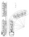
- the trailer shown in Figures 1 through 3comprises a chassis 1' with one rigid steerable axle 2' to whose ends have been secured wheels 3' and 4', which can be twin wheels if needed.
- the axle 2'is secured to the chassis 1' by a triangle or a V-support 5', articulated at one point to the middle of the axle 2' by a ball joint 11' and journalled at two points to opposite sides of the chassis 1' by means of joints 12' and 13'.
- This suspensionpermits a vertical flexible movement or a vertical rotation and a steering horizontal rotation of the axle 2', but prevents a lateral movement of the axle 2' under certain conditions.
- Supporting members S'e.g. rigid levers or springs, e.g. bearing or parabolic springs, secured concentrically or eccentrically to the axle 2', are arranged between the axle 2' and the trailer chassis 1' at both ends of the axle 2.
- suspension members S1'have been arranged at both ends of its supporting members S', which are secured to the chassis 1' by means of said suspension members.
- the supporting members S' and the suspension members S1'are shown in Figure 1 only, because if shown in Figure 2 and 3, it would only complicate understanding the present invention.
- These membersare previously known in the art and a more detailed description can be found e.g. in the above Finnish patents 84,895 and 89,570.
- a trailersince a trailer is concerned, it also comprises a tow bar 10', in this case arranged to rotate with a vertical axle 9' secured to the chassis 1' front or relative to the centre line of the vertical axle 9'.
- the vertical axle 9'is journalled to the chassis 1'.
- the tow bar 10'is secured to the vertical axle 9' via a transverse steering lever 8', on which the tow bar 10' is mounted rotatably relative to a transverse horizontal axle by means of bearings 18 and 19 on both sides of the vertical axle 9'.
- the reference numeral 20'refers to the towing eyelet of the tow bar 10'.
- supporting arms 6' and 7'are arranged between the steering lever 8' and the axle 2', the arms being fastened at one end to the steering lever 8' on opposite sides of said vertical axle 9' by means of ball joints 15' and 17', and at the other end underneath the axle 2' by means of ball joints 14' and 16' on opposite sides of the articulation point 11' of the triangle support 5' therein.
- the supporting arms 6' and 7'also support the axle 2' and the support forces of the axle 2' in the longitudinal direction of the trailer are transmitted to the chassis 1 via the supporting arms 6' and 7', and further via the vertical axle 9' in so far as the axle support forces are not transmitted to the chassis 1' via the triangle support 5'.
- the assembly shown in Figures 1 to 3is suitable as an axle steering assembly in trailers where an inexpensive and simple structure is called for.
- This assemblyprovides preferably biaxial and triaxial trailers.
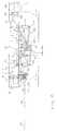
- a trailer equipped with two biaxial bogiesis shown in Figures 4 to 6. All axles, wheels and triangle supports and their articulations are similar to those in the assemblies shown in Figures 1 to 3 and have been denoted by the same reference numerals, but without the apostrophe. Also the supporting members S and the suspension members S1 are similar to the supporting members S' and the suspension members S1' shown in Figures 1 to 3. The suspension of the suspension members S1 to the chassis 1 is similar to the above except in the middle of the axles in each bogie, where the suspension members S1 are supported on equalizer levers (not shown in the drawings) arranged in the chassis 1. These assemblies are also known from prior art, and described e.g. in the above Finnish patents 84,895 and 89,570. This known support member and suspension lever arrangement has been shown only in Figure 4 for clarity, and even there only in connection with the first axle.
- the tow bar arrangementdeviates here from the solutions of Figures 1 to 3 in that the vertical axle 9 of the tow bar 10 is secured to the chassis 1 and also rotatably around a horizontal axle 21, and the horizontal bearing arrangement 18, 19 of the tow bar 10 to the steering lever 8 is located at a specified point between a line formed by the articulations 15 and 17 of said horizontal axle 21 and the supporting arms 6 and 7.
- the distance of the horizontal bearing application 18, 19 from the horizontal axle 21is denoted by the letter A and the distance of the horizontal axle 21 from a line formed by the support arms 6 and 7 by the letter B.
- the supporting arms 6 and 7 with their articulations 15, 17 and 14, 16are as in Figures 1 to 3.
- the division ratio of the tractive forcee.g. so that a greater tractive force rests on the chassis 1 than on the axles 2. This is the case in steep ascents when at the same time the resistance to motion of the road is low because of quality surface.
- the assembly of Figures 4 to 6further comprises second steering levers 22 and 24, journalled between the axles 2 of the first bogie to the chassis 1 on its opposite sides and extending downwards from the chassis, to which said axles 2 are coupled via corresponding longitudinal supports 27, 29 and 28, 30 on opposite sides of the chassis 1.
- the axle articulations of the longitudinal supports 27 and 28 on the side of the first axleare denoted by reference numerals 42 and 44, and the steering lever articulations, arranged at the ends of the steering levers 22 and 24, by reference numerals 43 and 45.
- axle articulations of the longitudinal supports 29 and 30 on the side of the second axleare denoted by reference numerals 47 and 49, and the steering lever articulations, arranged between the articulations 38 and 39 of the steering levers 22 and 24 and articulations 43 and 45, by reference numerals 46 and 48.
- a symmetry lever 26is further arranged, to opposite sides of whose bearing point 37 are secured connecting rods 31 and 32 by means of joints 51 and 53, the rods being secured together with the second steering levers 22 and 24 at one end to third steering levers 23 and 25, arranged in the same bearing application 38, 39, by joints 50 and 52, so that the second and third steering levers are immobile relative to each other and arranged at the same side of the bearing line, i.e. underneath it.
- the trailing bogieis symmetrical relative to the front bogie or, that is, its mirror image except that it has no connecting rod nor tow bar arrangements symmetrical with the front bogie.
- the longitudinal supportsare denoted by reference numerals 59, 61 and 58, 60.
- Their axle articulationsare denoted by reference numerals 64, 68 and 62, 66, and the articulations to the steering levers 35 and 36 by reference numerals 65, 69 and 63, 67.
- the front longitudinal supports 59 and 61 of the trailing bogieare articulated to the steering levers 35 and 36 at the same distance from their bearing points 70 and 71 as the rear longitudinal supports 29 and 30 from the bearing points 38 and 39 of the steering levers 22 and 24, and the rear longitudinal supports 58 and 60 of the trailing bogie in the same way as the front longitudinal supports 27 and 28 of the front bogie, if the trailing bogie is to follow the front bogie in curves. If the bogie is to have different turning radiuses, a lever ratio difference is selected between the front and the trailing bogies.
- Fourth steering levers 40 and 41extending upwards from the bearing applications 70 and 71, are secured immobile relative to the steering levers 35 and 36 to the bearing applications 70 and 71 of the steering levers 35 and 36 of the trailing bogie (in this case said steering levers 35 and 36 may be called fifth steering levers).
- These fourth steering levers 40 and 41have been connected by connecting rods 33 and 34 to said symmetry lever 26 by joints 55, 57 and 54, 56 in order for the axles of the trailing bogie to turn symmetrically with the axles of the front bogie.
- the axle assembly of the tow bar construction of Figure 8corresponds essentially to the front axle structure shown in Figures 4 to 6.
- the front end of the actual tow bar constructionpartially corresponds to the structure shown in Figures 1 to 3.
- the differenceis that the control force and movement are led from over to the middle of the tandem axles by means of a steering lever 8"' fastened to the upper end of the vertical axle 9'.
- the steering movement of the tow bar 10'is transmitted to a steering lever 8a"' by means of horizontal bearing applications 17' and 18' and further to the vertical axle 9' and further via the steering lever 8"' and via supporting arms 6"' and 7''' to auxiliary arms 23a and 25a of the steering levers 23 and 25, and this way controls the trailer steering lever system.
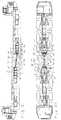
- axles, wheels, triangle supports with their articulations, the support and suspension members of the axles, and the means connecting and controlling the axles in the transport vehicle combination of Figures 9 to 11are similar to those in the assembly shown in Figures 4 to 6. These members have not, however, been numbered other than in the immediate vicinity of the tow bar construction.
- each vehicleThe cabs and controls of each vehicle are arranged at the extreme ends of the formed combination, so that the combination can be driven from either end according to the need and operates in practice so that the vehicle chosen to be driven operates as the tractor or the steering vehicle and the other as the trailer.
- the left hand vehiclehas been described as the towing vehicle, i.e. the tractor, and the right hand vehicle as the vehicle to be towed, i.e. the trailer.
- the tow bar 10" connecting the vehicles at their rear endsis connected to the rear ends of the vehicle by vertical bearing applications 9" and horizontal bearing applications 18", 19" and 21", essentially similar to those in Figures 4 to 6, and hence not described in any more detail here.
- the steering lever 8" associated with the tow bar and its suspensions (6", 7") to the axles 2are essentially similar to those in Figures 4 to 6.
- the tow bar 10" concernedis further equipped with additional articulation and associated locking and releasing members to be described below.
- horizontal plates 74", 75" and 76", 77"are fastened to the horizontal axle assemblies 18", 19", respectively. Between these plates have been secured journals equipped with ball joints 78", 80"' by means of coupling pins 79" and 81" that run through said horizontal plates and ball joints.
- Axially sliding locking members 71", 72"are journalled to the tow bar 10', and one journal at a time can be locked by the locking members so that it is essentially prevented from rotating horizontally, i.e.
- both ends of the locking members 71", 72"comprise locking safety wedges 83", 84"; 85", 86" which can be locked into locking grooves 87", 88"; 89", 90” (see Figures 11 and 12) formed in the plates 74", 75" and 76", 77", respectively.
- the locking members 71", 72"are moved by a pin 82" in an actuator 73".
- the actuator 73"is fixedly secured to the middle of the tow bar 10".
- the pin 82"can move hydraulically, pneumatically, electrically or mechanically.
- the pin 82"has two positions only, i.e. its locks the journal on the side of the vehicle to be towed and simultaneously releases the journal on the side of the towing vehicle. The selection can be made automatically or it can be selected when the driver starts to prepare the combination for transport.
- the locking members 71", 72"allow a turning movement relative to each other, and a turning movement of the tow bar 10" around its axle, the longitudinal tilting between the transport vehicles being unobstructed.
- the free rotation of the journal on the side of the tractor in a plane parallel to the surface of the roadis preferable e.g. because the tractor axles can be turned from one extreme position to another even when the combination is not moving.
- Combinations to be transported to both directions, such as have been described here,are needed in surroundings where arranging space for turning the combination becomes significantly expensive.
- Such typical surroundingsinclude e.g. a drift mine.
- the transport vehicle combinationcan comprise more than two transport vehicles, e.g. three or more, both extreme ends or only one extreme end of the combination comprising a motorized towing vehicle. Only one motor can move the combination and it can be arranged in any one of the vehicles.
- the combinationmay also comprise vehicles and/or trailers in an arbitrary order.
- the tow bars of the invention connecting the transport vehiclescan also be chosen according to the particular need.
- the axlescan be single axles or tandem axles according to the need, and their number can also vary according to the need.
- the driver of the combinationcan also be replaced by automatic control with the steering mechanisms remaining as described above.
Landscapes
- Engineering & Computer Science (AREA)
- Chemical & Material Sciences (AREA)
- Combustion & Propulsion (AREA)
- Transportation (AREA)
- Mechanical Engineering (AREA)
- Steering-Linkage Mechanisms And Four-Wheel Steering (AREA)
- Vehicle Body Suspensions (AREA)
- Body Structure For Vehicles (AREA)
- Structure Of Belt Conveyors (AREA)
- Automatic Cycles, And Cycles In General (AREA)
- Tents Or Canopies (AREA)
- Mechanical Pencils And Projecting And Retracting Systems Therefor, And Multi-System Writing Instruments (AREA)
- Yarns And Mechanical Finishing Of Yarns Or Ropes (AREA)
- Crystals, And After-Treatments Of Crystals (AREA)
- Refuge Islands, Traffic Blockers, Or Guard Fence (AREA)
- Spinning Or Twisting Of Yarns (AREA)
- Guiding Agricultural Machines (AREA)
Abstract
Description
- one steering axle and one or more fixed axles
- two steering axles and one or more fixed axles
- three steering axles and one or more fixed axles
- four steering axles and one or more fixed axles
- two steering axles
- three steering axles
- four steering axles.
Claims (15)
- A tow bar construction for a trailer, the construction comprisingcharacterized in thatat least two rigid axles (2),wheels (3, 4) secured to the ends of each axle (2),supporting members (S) or springs arranged at both ends of eachaxle between the axles (2) and the chassis (1) of the vehicle,a tow bar (10), journalled to the front of the chassis (1) rotatablyrelative to a vertical and a horizontal axle, and means for turning the axle (2),the means for turning the axle (2) comprising a steering lever (8)secured to the tow bar (10) rotatably relative to the centre line of its verticalaxle (9), and supporting arms (6, 7), secured at one end to the steering leveron opposite sides of said vertical axle (9), and at the other end to the first axle,(2) on opposite sides of an articulation point (11) of the axle (2), said pointsituating in the middle of the axle, andmeans coupled to the first axle for implementing the turningmovement also in at least one axle located behind the first axle,second steering levers (22, 24) are journalled to the chassis (1) onits opposite sides between the first and the second axle, said axles beingcoupled to the levers via longitudinal supports (27, 29; 28, 30) on oppositesides of the chassis, respectively, andwhereby each turnable rigid axle (2) for allowing turning movementcomprises:suspension members (S1) arranged at both ends of bothsupporting members (S) or springs of the axle (2), the suspension membersbeing secured at one end to the supporting members (S) or springs and at theother end to the chassis (1) of the vehicle either directly or indirectly, anda triangle support (5), articulated at the articulation point (11) ofthe axle (2) and journalled at two points to opposite sides of the chassis (1) ofthe vehicle,
- A tow bar construction as claimed in claim 1,characterizedin that the front longitudinal supports (27, 28) are secured to thesecond steering levers (22, 24) at a different distance from their bearing point(38, 39) than the rear longitudinal supports (29, 30) in order for the travel trackof the wheels in different axles to be harmonized in curves.
- A tow bar construction as claimed in claim 1,characterizedin that the vertical axle (9) of the tow bar (10) is journalled at its upperend to the chassis (1) rotatably relative to a relative thereto transverse,horizontal axle, and that the horizontal axle securing (18) of the tow bar (10) tothe vertical axle (9) is located at a predetermined height between thehorizontal axle (21) and the articulation (15, 17) of the supporting arms (6, 7)arranged in the vertical axle (9) in order for the tow bar forces to be distributedbetween the chassis and the axle assembly as desired.
- A tow bar construction for a trailer as claimed in claim 1, theconstruction comprising first and second bogie, each having two rigid axles(2), said triangle support (5) being associated with each axle,
characterized in that the means for turning the axle (2)further comprisea symmetry lever (26) journalled behind the second axle of the first'bogie to the chassis at the point of its centre line, connecting rods (31, 32)being secured to opposite sides of the bearing point (37) of the symmetrylever, the rods being secured at one end to the second steering levers (22,24),connecting rods (33, 34), secured at one end to opposite sides ofthe symmetry lever (26) and at the other end between the axles of the secondbogie to fourth steering levers (40, 41) journalled to opposite sides of thechassis, andrear bogie longitudinal supports (58, 59; 60, 61), articulatedbetween the rear bogie axles and fifth steering levers (35, 36) fixedly securedto the fourth steering levers (40, 41). - A tow bar construction as claimed in claim 4,characterizedin that the longitudinal support arrangements of the front and rearbogies and the force effects of the steering arm levers are mutually reverse,and they thus eliminate the braking forces, accelerating forces and motionresistance forces of the bogies in the lever mechanism.
- A tow bar construction as claimed in claim 4,characterizedin that the vertical axle (9) of the tow bar (10) is journalled at its upperend to the chassis (1) rotatably relative to a relative thereto transversehorizontal axle, and that the horizontal axle securing (18) of the tow bar (10) tothe vertical axle (9) is located at a predetermined height between thehorizontal axle (21) and the articulation (15, 17) of the supporting arms (6, 7)arranged in the vertical axle (9) in order for the tow bar forces to be distributed between the chassis and the axle assembly as desired.
- A transport vehicle combination formed of two vehicles,
characterized in that the vehicles are joined together with atow bar (10") construction as claimed in claims 1 - 6, wherein the cabs and thecontrols of each vehicle are arranged at the extreme ends of the formedcombination, the combination being able to be driven from either endaccording to the need. - A transport vehicle combination as claimed in claim 7,characterized in that both ends of the tow bar (10") comprise anadditional articulation (78", 79"; 80", 81") and means (71", 74", 75"; 72", 76",77") for locking and releasing the additional articulation at only one end at atime, the end of the tow bar (10"), which is released and is always on the sideof the vehicle acting as the tractor, being able to rotate in a plane parallel tothe surface of the road without affecting the steering lever (8") on that side.
- A transport vehicle combination as claimed in claim 7,characterizedin that the additional articulations (78", 79"; 80", 81") areformed of coupling pins (79", 81") secured between horizontal plates (74",75"; 76", 77") fastened to the horizontal bearing applications (18", 19"), thepins being pushed through ball joints (78", 80") at the ends of the tow bar(10") arranged between said plates, and that the means for locking andreleasing the additional articulation are formed of locking members (71", 72")that slide by means of an actuator (73") and a pin (82") from the middle of thetow bar (10"), the locking members being able to be locked into counterlocking members arranged in the horizontal plates (74", 75"; 76", 77").
- A transport vehicle combination as claimed in claim 7,characterized in that both vehicles are motorized and operate inpractice so that the vehicle selected to be driven operates as the tractor andthe other as the trailer.
- A transport vehicle combination as claimed in claim 7,characterized in that only one of the vehicles comprises a motor.
- A transport vehicle combination formed of at least three vehicles,
characterized in that the vehicles are joined together with atow bar construction as claimed in claims 1 - 6, wherein at least the vehicles atthe extreme ends of the combination comprise cabs and controls, arranged atthe extreme ends of the combination, the combination being able to be drivenfrom either end according to the need. - A transport vehicle combination as claimed in claim 12,characterized in that at least the vehicles at the extreme ends aremotorized vehicles an operate in practice so that the vehicle selected to bedriven operates as the tractor and the others as the trailer.
- A transport vehicle combination as claimed in claim 12,characterized in that only one of the vehicles comprises a motor.
- A transport vehicle combination as claimed in any one of claims7 through 14,characterized in that it is equipped with automaticcontrol.
Applications Claiming Priority (3)
| Application Number | Priority Date | Filing Date | Title |
|---|---|---|---|
| FI956283 | 1995-12-27 | ||
| FI956283AFI110076B (en) | 1995-12-27 | 1995-12-27 | Shaft construction for means of transport and means of transport and a means of transport |
| PCT/FI1996/000696WO1997024248A1 (en) | 1995-12-27 | 1996-12-23 | Tow bar construction for transport vehicles and transport vehicle combinations, and a transport vehicle combination |
Publications (2)
| Publication Number | Publication Date |
|---|---|
| EP0869896A1 EP0869896A1 (en) | 1998-10-14 |
| EP0869896B1true EP0869896B1 (en) | 2002-09-18 |
Family
ID=8544614
Family Applications (1)
| Application Number | Title | Priority Date | Filing Date |
|---|---|---|---|
| EP96943145AExpired - LifetimeEP0869896B1 (en) | 1995-12-27 | 1996-12-23 | Tow bar construction for transport vehicles and transport vehicle combinations, and a transport vehicle combination |
Country Status (12)
| Country | Link |
|---|---|
| US (1) | US6135484A (en) |
| EP (1) | EP0869896B1 (en) |
| JP (1) | JP2000502630A (en) |
| AT (1) | ATE224319T1 (en) |
| AU (1) | AU715513B2 (en) |
| CA (1) | CA2241108C (en) |
| DE (1) | DE69623810T2 (en) |
| FI (1) | FI110076B (en) |
| NO (1) | NO314886B1 (en) |
| PL (1) | PL181935B1 (en) |
| RU (1) | RU2161096C2 (en) |
| WO (1) | WO1997024248A1 (en) |
Cited By (1)
| Publication number | Priority date | Publication date | Assignee | Title |
|---|---|---|---|---|
| EP4194233A1 (en) | 2021-12-10 | 2023-06-14 | VBG Group AB (Publ) | A controllable drawbar arrangement and method for controlling such drawbar arrangement |
Families Citing this family (23)
| Publication number | Priority date | Publication date | Assignee | Title |
|---|---|---|---|---|
| FI106625B (en) | 1998-07-10 | 2001-03-15 | Tamrock Oy | Bogie design |
| NL1016576C2 (en)* | 2000-11-09 | 2002-05-14 | Transp Industry Dev Ct Bv | Vehicle provided with a chassis with a first wheel pair and a second wheel pair. |
| US6488114B1 (en)* | 2001-02-12 | 2002-12-03 | Balzer, Inc. | Grain cart |
| US20090273159A1 (en) | 2007-05-05 | 2009-11-05 | American Heavy Moving and Rigging, Inc. | Dual lane multi-axle transport vehicle |
| US7484748B2 (en)* | 2005-09-08 | 2009-02-03 | Cnh Canada, Ltd. | Slow response steering connection assembly |
| US7461854B2 (en)* | 2005-11-14 | 2008-12-09 | Cnh Canada, Ltd. | Steering connection assembly |
| US7540522B2 (en)* | 2005-11-30 | 2009-06-02 | Cnh Canada, Ltd. | Steering connection assembly between multiple towed implements |
| US8286984B2 (en)* | 2007-12-18 | 2012-10-16 | Dillon Ben N | Articulated combine with unloading and rear bogey steering architecture |
| GB0810643D0 (en)* | 2008-06-11 | 2008-07-16 | Firth Charles B | Mine detonating apparatus |
| US9062940B2 (en) | 2008-06-11 | 2015-06-23 | Charles Basil Firth | Mine detonating apparatus |
| US9096265B2 (en)* | 2013-03-15 | 2015-08-04 | Kevin Stuart Carr | Steerable trailer chassis |
| RU167636U1 (en)* | 2016-03-21 | 2017-01-10 | Федеральное государственное автономное образовательное учреждение высшего образования "Уральский федеральный университет имени первого Президента России Б.Н. Ельцина" | TRAILER FRONT AXLE DRIVING MECHANISM |
| AU2017276355B2 (en)* | 2016-12-23 | 2023-04-27 | Spark, Ian James DR | Improved articulated vehicle |
| US10351172B2 (en) | 2017-02-28 | 2019-07-16 | Brandt Agricultural Products Ltd. | Tandem steering for a grain cart |
| US10377290B2 (en) | 2017-02-28 | 2019-08-13 | Brandt Agricultural Products Ltd. | Spout autorotate for a grain cart |
| US10278328B2 (en) | 2017-02-28 | 2019-05-07 | Brandt Agricultural Products Ltd. | Grain cart with automatic unloading of a predetermined weight of crop material |
| AU2018203105B2 (en)* | 2017-05-28 | 2023-10-05 | Spark, Ian James DR | Improved Articulated Vehicles |
| US10551832B2 (en)* | 2017-08-29 | 2020-02-04 | Cnh Industrial America Llc | Method and system for transporting an autonomous agricultural vehicle |
| AR114769A1 (en)* | 2018-04-11 | 2020-10-14 | BIS Industries Ltd | HEAVY TRANSPORT VEHICLE |
| DE102019204442A1 (en)* | 2019-03-29 | 2020-10-01 | Goldhofer Ag | Heavy duty vehicle |
| DE102020115469B4 (en) | 2020-06-10 | 2022-04-21 | Sommer Gmbh | Dolly trailer, train with such a dolly trailer and method for operating such a train |
| US20230050768A1 (en)* | 2021-08-11 | 2023-02-16 | Unverferth Manufacturing Company, Inc. | Header transport with steerable walking tandem axles |
| US20230397522A1 (en)* | 2022-06-09 | 2023-12-14 | Deere & Company | Row unit overlap avoidance system and method |
Family Cites Families (24)
| Publication number | Priority date | Publication date | Assignee | Title |
|---|---|---|---|---|
| DE342179C (en)* | ||||
| DE342861C (en)* | 1917-06-13 | 1921-10-26 | Achille Arato | Steering device for trailer |
| US1378436A (en)* | 1919-03-12 | 1921-05-17 | Ferruccio Botta | Steering-gear for vehicles used as trailers |
| US1585133A (en)* | 1923-12-11 | 1926-05-18 | Isem Bv | Steering device for trailers |
| FR778577A (en)* | 1933-09-19 | 1935-03-15 | ||
| DE923770C (en)* | 1942-07-07 | 1955-02-21 | Karl Kaessbohrer | Truck with sets of wheels carried by bogies |
| DE870069C (en)* | 1949-09-01 | 1953-03-09 | Emil H Von Lienen Fa | Steering device, especially for motor vehicle trailers |
| US2785909A (en)* | 1954-09-03 | 1957-03-19 | Barnard Ralph | Steering mechanism for vehicles |
| DE1115591B (en)* | 1958-12-24 | 1961-10-19 | Maschf Augsburg Nuernberg Ag | Steering device for a wagon train |
| NL6908160A (en)* | 1969-05-29 | 1970-12-01 | ||
| US3690698A (en)* | 1970-11-30 | 1972-09-12 | Carl E Humes | Steering assembly for trailers |
| NL183280C (en)* | 1978-05-24 | 1988-09-16 | Welgro Bv | VEHICLE. |
| NL8003857A (en)* | 1980-07-03 | 1982-02-01 | Welgro Bv | VEHICLE. |
| DE3616457C1 (en)* | 1986-05-15 | 1987-11-26 | Schultz Rainer M Dipl Ing | Track-free, two-component vehicle train |
| IT1201636B (en)* | 1986-07-16 | 1989-02-02 | Sio Ind Ossigeno Altri Gas | STEERING DEVICE FOR SEMI-TRAILERS WITH TWO STEERING AXLES |
| DE3801746A1 (en)* | 1987-07-04 | 1989-01-12 | Roland Rief | TRAILER DEVICE, IN PARTICULAR FOR AGRICULTURAL TRAIN VEHICLES |
| GB2232133A (en)* | 1989-04-20 | 1990-12-05 | Suehiro Ind Limited | Trailer with interconnected steerable axles |
| FR2654697B1 (en)* | 1989-11-20 | 1995-02-17 | Giovanni Tonarelli | AXLE TRAIN FOR AGRICULTURAL, ROAD VEHICLES, CONSTRUCTION SITE AND THE LIKE, WHICH MAY INTERRUPT THEIR PARALLELISM DURING TURNS, AND BECOME SELF-VIRUS. |
| FI84895C (en)* | 1990-03-26 | 1992-02-10 | Sisu Auto Ab Kuorma Autoteolli | AXEL CONSTRUCTION FOER ETT NYTTOFORDON. |
| RU2019460C1 (en)* | 1991-02-01 | 1994-09-15 | Белорусский технологический институт им.С.М.Кирова | Method for adjusting cross-shaped coupler of transport vehicle |
| FI89570C (en)* | 1991-09-27 | 1993-10-25 | Sisu Auto Ab Kuorma Autoteolli | AXEL CONSTRUCTION FOER ETT NYTTOFORDON |
| US5340142A (en)* | 1993-03-10 | 1994-08-23 | E-Z Trail, Inc. | Towing tongue assembly |
| US5364117A (en)* | 1993-08-10 | 1994-11-15 | Keith Peter G | Method and apparatus for connecting a tow vehicle to a trailer having a front axle assembly which pivots about a verticle axis |
| DE4334742C2 (en)* | 1993-10-12 | 1997-04-30 | Francke Renate | Deactivatable axle steering |
- 1995
- 1995-12-27FIFI956283Apatent/FI110076B/ennot_activeIP Right Cessation
- 1996
- 1996-12-23DEDE69623810Tpatent/DE69623810T2/ennot_activeExpired - Lifetime
- 1996-12-23PLPL96327464Apatent/PL181935B1/ennot_activeIP Right Cessation
- 1996-12-23EPEP96943145Apatent/EP0869896B1/ennot_activeExpired - Lifetime
- 1996-12-23JPJP9524045Apatent/JP2000502630A/ennot_activeCeased
- 1996-12-23ATAT96943145Tpatent/ATE224319T1/enactive
- 1996-12-23CACA002241108Apatent/CA2241108C/ennot_activeExpired - Fee Related
- 1996-12-23USUS09/091,720patent/US6135484A/ennot_activeExpired - Fee Related
- 1996-12-23AUAU11973/97Apatent/AU715513B2/ennot_activeCeased
- 1996-12-23RURU98114088/28Apatent/RU2161096C2/ennot_activeIP Right Cessation
- 1996-12-23WOPCT/FI1996/000696patent/WO1997024248A1/enactiveIP Right Grant
- 1998
- 1998-06-23NONO19982926Apatent/NO314886B1/ennot_activeIP Right Cessation
Cited By (1)
| Publication number | Priority date | Publication date | Assignee | Title |
|---|---|---|---|---|
| EP4194233A1 (en) | 2021-12-10 | 2023-06-14 | VBG Group AB (Publ) | A controllable drawbar arrangement and method for controlling such drawbar arrangement |
Also Published As
| Publication number | Publication date |
|---|---|
| CA2241108A1 (en) | 1997-07-10 |
| JP2000502630A (en) | 2000-03-07 |
| DE69623810D1 (en) | 2002-10-24 |
| US6135484A (en) | 2000-10-24 |
| FI956283A0 (en) | 1995-12-27 |
| NO982926D0 (en) | 1998-06-23 |
| FI110076B (en) | 2002-11-29 |
| RU2161096C2 (en) | 2000-12-27 |
| PL327464A1 (en) | 1998-12-07 |
| EP0869896A1 (en) | 1998-10-14 |
| AU1197397A (en) | 1997-07-28 |
| CA2241108C (en) | 2004-10-19 |
| DE69623810T2 (en) | 2003-05-28 |
| FI956283A7 (en) | 1997-06-28 |
| AU715513B2 (en) | 2000-02-03 |
| NO982926L (en) | 1998-06-23 |
| PL181935B1 (en) | 2001-10-31 |
| ATE224319T1 (en) | 2002-10-15 |
| NO314886B1 (en) | 2003-06-10 |
| WO1997024248A1 (en) | 1997-07-10 |
Similar Documents
| Publication | Publication Date | Title |
|---|---|---|
| EP0869896B1 (en) | Tow bar construction for transport vehicles and transport vehicle combinations, and a transport vehicle combination | |
| FI74667C (en) | Control device for multi-axle semi-trailers. | |
| US5364113A (en) | Self-steering axle for vehicles | |
| US4221398A (en) | Highway trailer of selectively variable width | |
| EP0375761A1 (en) | Heavy duty transport vehicle | |
| US3291503A (en) | Automatically steerable trailer | |
| US20070262552A1 (en) | Suspension system for a transport vehicle | |
| US5088570A (en) | Steerable rear dual axle system for large trucks | |
| EP0053001A1 (en) | Improvements in or relating to trailer and semitrailer vehicles | |
| US5163700A (en) | Dual rear axle assembly for large vehicles | |
| US5305844A (en) | Remote steering of on-highway vehicles | |
| US3993326A (en) | Vehicle with self-steering trailer | |
| US5139103A (en) | Remote steering of on-highway vehicles | |
| EP0521882B1 (en) | Axle construction for a commercial vehicle | |
| US5135064A (en) | Remote steering of on-highway vehicles | |
| RU231099U1 (en) | VEHICLE CARRIAGE | |
| US2902293A (en) | Transportation vehicle | |
| GB2116924A (en) | Third axle unit for tractor | |
| US4022342A (en) | Self-loading carrier with trailing end bogie | |
| JPH08244429A (en) | Rear axle device for trucks | |
| WO2000021821A1 (en) | Self tracking mechanism for axle assemblies | |
| EP0239344A2 (en) | Improvements relating to trailers | |
| AU752615B2 (en) | Self tracking mechanism for axle assemblies | |
| CA1067536A (en) | Steerable trailer suspension system with beams, rockers, spindles and steering control | |
| JP2000128011A (en) | Rear wheel steering system |
Legal Events
| Date | Code | Title | Description |
|---|---|---|---|
| PUAI | Public reference made under article 153(3) epc to a published international application that has entered the european phase | Free format text:ORIGINAL CODE: 0009012 | |
| 17P | Request for examination filed | Effective date:19980618 | |
| AK | Designated contracting states | Kind code of ref document:A1 Designated state(s):AT CH DE FR GB IT LI SE | |
| 17Q | First examination report despatched | Effective date:19991203 | |
| GRAG | Despatch of communication of intention to grant | Free format text:ORIGINAL CODE: EPIDOS AGRA | |
| GRAG | Despatch of communication of intention to grant | Free format text:ORIGINAL CODE: EPIDOS AGRA | |
| GRAH | Despatch of communication of intention to grant a patent | Free format text:ORIGINAL CODE: EPIDOS IGRA | |
| RAP1 | Party data changed (applicant data changed or rights of an application transferred) | Owner name:SANDVIK TAMROCK OY | |
| GRAH | Despatch of communication of intention to grant a patent | Free format text:ORIGINAL CODE: EPIDOS IGRA | |
| GRAA | (expected) grant | Free format text:ORIGINAL CODE: 0009210 | |
| AK | Designated contracting states | Kind code of ref document:B1 Designated state(s):AT CH DE FR GB IT LI SE | |
| REF | Corresponds to: | Ref document number:224319 Country of ref document:AT Date of ref document:20021015 Kind code of ref document:T | |
| REG | Reference to a national code | Ref country code:GB Ref legal event code:FG4D | |
| REG | Reference to a national code | Ref country code:CH Ref legal event code:EP | |
| REF | Corresponds to: | Ref document number:69623810 Country of ref document:DE Date of ref document:20021024 | |
| REG | Reference to a national code | Ref country code:CH Ref legal event code:NV Representative=s name:A. BRAUN, BRAUN, HERITIER, ESCHMANN AG PATENTANWAE | |
| ET | Fr: translation filed | ||
| PLBE | No opposition filed within time limit | Free format text:ORIGINAL CODE: 0009261 | |
| STAA | Information on the status of an ep patent application or granted ep patent | Free format text:STATUS: NO OPPOSITION FILED WITHIN TIME LIMIT | |
| 26N | No opposition filed | Effective date:20030619 | |
| REG | Reference to a national code | Ref country code:CH Ref legal event code:PFA Owner name:SANDVIK TAMROCK OY Free format text:SANDVIK TAMROCK OY#PIHTISULUNKATU 9#33330 TAMPERE (FI) -TRANSFER TO- SANDVIK TAMROCK OY#PIHTISULUNKATU 9#33330 TAMPERE (FI) | |
| PGFP | Annual fee paid to national office [announced via postgrant information from national office to epo] | Ref country code:FR Payment date:20110104 Year of fee payment:15 Ref country code:AT Payment date:20101214 Year of fee payment:15 | |
| PGFP | Annual fee paid to national office [announced via postgrant information from national office to epo] | Ref country code:CH Payment date:20101224 Year of fee payment:15 | |
| PGFP | Annual fee paid to national office [announced via postgrant information from national office to epo] | Ref country code:IT Payment date:20101227 Year of fee payment:15 Ref country code:GB Payment date:20101221 Year of fee payment:15 | |
| PGFP | Annual fee paid to national office [announced via postgrant information from national office to epo] | Ref country code:SE Payment date:20111223 Year of fee payment:16 | |
| PGFP | Annual fee paid to national office [announced via postgrant information from national office to epo] | Ref country code:DE Payment date:20111222 Year of fee payment:16 | |
| REG | Reference to a national code | Ref country code:CH Ref legal event code:PL | |
| GBPC | Gb: european patent ceased through non-payment of renewal fee | Effective date:20111223 | |
| REG | Reference to a national code | Ref country code:FR Ref legal event code:ST Effective date:20120831 | |
| PG25 | Lapsed in a contracting state [announced via postgrant information from national office to epo] | Ref country code:LI Free format text:LAPSE BECAUSE OF NON-PAYMENT OF DUE FEES Effective date:20111231 Ref country code:CH Free format text:LAPSE BECAUSE OF NON-PAYMENT OF DUE FEES Effective date:20111231 Ref country code:GB Free format text:LAPSE BECAUSE OF NON-PAYMENT OF DUE FEES Effective date:20111223 | |
| PG25 | Lapsed in a contracting state [announced via postgrant information from national office to epo] | Ref country code:IT Free format text:LAPSE BECAUSE OF NON-PAYMENT OF DUE FEES Effective date:20111223 | |
| REG | Reference to a national code | Ref country code:AT Ref legal event code:MM01 Ref document number:224319 Country of ref document:AT Kind code of ref document:T Effective date:20111223 | |
| PG25 | Lapsed in a contracting state [announced via postgrant information from national office to epo] | Ref country code:AT Free format text:LAPSE BECAUSE OF NON-PAYMENT OF DUE FEES Effective date:20111223 | |
| PG25 | Lapsed in a contracting state [announced via postgrant information from national office to epo] | Ref country code:FR Free format text:LAPSE BECAUSE OF NON-PAYMENT OF DUE FEES Effective date:20120102 | |
| PG25 | Lapsed in a contracting state [announced via postgrant information from national office to epo] | Ref country code:SE Free format text:LAPSE BECAUSE OF NON-PAYMENT OF DUE FEES Effective date:20121224 | |
| REG | Reference to a national code | Ref country code:DE Ref legal event code:R119 Ref document number:69623810 Country of ref document:DE Effective date:20130702 | |
| PG25 | Lapsed in a contracting state [announced via postgrant information from national office to epo] | Ref country code:DE Free format text:LAPSE BECAUSE OF NON-PAYMENT OF DUE FEES Effective date:20130702 |