EP0869256B1 - Rotary drill bit with gage definition region, method of manufacturing such a drill bit and method of drilling a subterranean formation - Google Patents
Rotary drill bit with gage definition region, method of manufacturing such a drill bit and method of drilling a subterranean formationDownload PDFInfo
- Publication number
- EP0869256B1 EP0869256B1EP98302621AEP98302621AEP0869256B1EP 0869256 B1EP0869256 B1EP 0869256B1EP 98302621 AEP98302621 AEP 98302621AEP 98302621 AEP98302621 AEP 98302621AEP 0869256 B1EP0869256 B1EP 0869256B1
- Authority
- EP
- European Patent Office
- Prior art keywords
- gage
- bit
- drill bit
- cutters
- definition region
- Prior art date
- Legal status (The legal status is an assumption and is not a legal conclusion. Google has not performed a legal analysis and makes no representation as to the accuracy of the status listed.)
- Expired - Lifetime
Links
- 230000015572biosynthetic processEffects0.000titleclaimsdescription35
- 238000005553drillingMethods0.000titleclaimsdescription16
- 238000000034methodMethods0.000titledescription6
- 238000004519manufacturing processMethods0.000titledescription2
- 238000005520cutting processMethods0.000claimsdescription140
- 239000010432diamondSubstances0.000claimsdescription13
- 229910003460diamondInorganic materials0.000claimsdescription12
- 239000000463materialSubstances0.000claimsdescription11
- 238000005299abrasionMethods0.000claimsdescription3
- 230000035515penetrationEffects0.000claimsdescription3
- 229910052582BNInorganic materials0.000claimsdescription2
- PZNSFCLAULLKQX-UHFFFAOYSA-NBoron nitrideChemical compoundN#BPZNSFCLAULLKQX-UHFFFAOYSA-N0.000claimsdescription2
- 230000001154acute effectEffects0.000claims1
- 238000005096rolling processMethods0.000claims1
- 238000005755formation reactionMethods0.000description31
- 239000011295pitchSubstances0.000description7
- 235000019801trisodium phosphateNutrition0.000description6
- 230000000694effectsEffects0.000description5
- 239000002184metalSubstances0.000description5
- 229910052751metalInorganic materials0.000description5
- 239000012530fluidSubstances0.000description4
- UONOETXJSWQNOL-UHFFFAOYSA-Ntungsten carbideChemical compound[W+]#[C-]UONOETXJSWQNOL-UHFFFAOYSA-N0.000description4
- 206010038933Retinopathy of prematurityDiseases0.000description3
- 239000011159matrix materialSubstances0.000description3
- 229910000831SteelInorganic materials0.000description2
- 239000011230binding agentSubstances0.000description2
- 230000015556catabolic processEffects0.000description2
- 238000000576coating methodMethods0.000description2
- 230000007423decreaseEffects0.000description2
- 230000003247decreasing effectEffects0.000description2
- 238000006731degradation reactionMethods0.000description2
- 230000001066destructive effectEffects0.000description2
- 239000010959steelSubstances0.000description2
- 229910001369BrassInorganic materials0.000description1
- 230000009286beneficial effectEffects0.000description1
- 239000010951brassSubstances0.000description1
- 239000011248coating agentSubstances0.000description1
- 238000001816coolingMethods0.000description1
- 230000003628erosive effectEffects0.000description1
- 230000001747exhibiting effectEffects0.000description1
- 230000008595infiltrationEffects0.000description1
- 238000001764infiltrationMethods0.000description1
- 238000002386leachingMethods0.000description1
- 238000012986modificationMethods0.000description1
- 230000004048modificationEffects0.000description1
- 239000002245particleSubstances0.000description1
- 238000010008shearingMethods0.000description1
- 229910052710siliconInorganic materials0.000description1
- 239000010703siliconSubstances0.000description1
- 239000000758substrateSubstances0.000description1
- WFKWXMTUELFFGS-UHFFFAOYSA-NtungstenChemical compound[W]WFKWXMTUELFFGS-UHFFFAOYSA-N0.000description1
- 229910052721tungstenInorganic materials0.000description1
- 239000010937tungstenSubstances0.000description1
Images


Classifications
- E—FIXED CONSTRUCTIONS
- E21—EARTH OR ROCK DRILLING; MINING
- E21B—EARTH OR ROCK DRILLING; OBTAINING OIL, GAS, WATER, SOLUBLE OR MELTABLE MATERIALS OR A SLURRY OF MINERALS FROM WELLS
- E21B10/00—Drill bits
- E21B10/26—Drill bits with leading portion, i.e. drill bits with a pilot cutter; Drill bits for enlarging the borehole, e.g. reamers
- E21B10/28—Drill bits with leading portion, i.e. drill bits with a pilot cutter; Drill bits for enlarging the borehole, e.g. reamers with non-expansible roller cutters
- E—FIXED CONSTRUCTIONS
- E21—EARTH OR ROCK DRILLING; MINING
- E21B—EARTH OR ROCK DRILLING; OBTAINING OIL, GAS, WATER, SOLUBLE OR MELTABLE MATERIALS OR A SLURRY OF MINERALS FROM WELLS
- E21B10/00—Drill bits
- E21B10/42—Rotary drag type drill bits with teeth, blades or like cutting elements, e.g. fork-type bits, fish tail bits
- E21B10/43—Rotary drag type drill bits with teeth, blades or like cutting elements, e.g. fork-type bits, fish tail bits characterised by the arrangement of teeth or other cutting elements
- E—FIXED CONSTRUCTIONS
- E21—EARTH OR ROCK DRILLING; MINING
- E21B—EARTH OR ROCK DRILLING; OBTAINING OIL, GAS, WATER, SOLUBLE OR MELTABLE MATERIALS OR A SLURRY OF MINERALS FROM WELLS
- E21B10/00—Drill bits
- E21B10/44—Bits with helical conveying portion, e.g. screw type bits; Augers with leading portion or with detachable parts
- E—FIXED CONSTRUCTIONS
- E21—EARTH OR ROCK DRILLING; MINING
- E21B—EARTH OR ROCK DRILLING; OBTAINING OIL, GAS, WATER, SOLUBLE OR MELTABLE MATERIALS OR A SLURRY OF MINERALS FROM WELLS
- E21B10/00—Drill bits
- E21B10/46—Drill bits characterised by wear resisting parts, e.g. diamond inserts
- E—FIXED CONSTRUCTIONS
- E21—EARTH OR ROCK DRILLING; MINING
- E21B—EARTH OR ROCK DRILLING; OBTAINING OIL, GAS, WATER, SOLUBLE OR MELTABLE MATERIALS OR A SLURRY OF MINERALS FROM WELLS
- E21B17/00—Drilling rods or pipes; Flexible drill strings; Kellies; Drill collars; Sucker rods; Cables; Casings; Tubings
- E21B17/10—Wear protectors; Centralising devices, e.g. stabilisers
- E21B17/1092—Gauge section of drill bits
Definitions
- This inventionrelates generally to rotary drill bits used in drilling subterranean wells and, more specifically, to drill bits having a gage definition portion or region that relatively gradually expands the diameter of the wellbore from that cut by the face cutters to substantially the full gage diameter of the bit.
- the equipment used in drilling operationsis well known in the art and generally comprises a drill bit attached to a drill string, including drill pipe and drill collars.
- a rotary table or other devicesuch as a top drive is used to rotate the drill string, resulting in a corresponding rotation of the drill bit.
- the drill collarswhich are heavier per unit length than drill pipe, are normally used on the bottom part of the drill string to add weight to the drill bit, increasing weight on bit (WOB). The weight of these drill collars presses the drill bit against the formation at the bottom of the borehole, causing it to drill when rotated.
- Downhole motorsare also sometimes employed, in which case the bit is secured to the output or drive shaft of the motor.
- a typical rotary drill bitincludes a bit body, with a connecting structure for connecting the bit body to the drill string, such as a threaded portion on a shank extending from the bit body, and a crown comprising that part of the bit fitted with cutting structures for cutting into an earth formation.
- the cutting structuresinclude a series of cutting elements made of a superabrasive material, such as polycrystalline diamond, oriented on the bit face at an angle to the surface being cut (i.e., side rake, back rake).
- the bit bodymay typically be formed from a cast or machined steel mass or a tungsten carbide matrix cast by infiltration with a liquified metal binder onto a blank which is welded to a tubular shank. Threads are then formed onto the free end of the shank to correspondingly match the threads of a drill collar.
- Cutting elementsare usually secured to the bit by preliminary bonding to a carrier element, such as a stud, post or elongated cylinder, which in turn is inserted into a pocket, socket or other aperture in the crown of the bit and mechanically or metallurgically secured thereto.
- a carrier elementsuch as a stud, post or elongated cylinder
- PDCpolycrystalline diamond compact
- cutting elementsusually of a circular or disc-shape comprising a diamond table bonded to a supporting WC substrate, may be brazed to a matrix-type bit after furnacing.
- freestanding (unsupported) metal-coated thermally stable PDCs(commonly termed TSPs) may be bonded into the bit body during the furnacing process used to fabricate a matrix-type drill bit.
- a TSPmay be formed by leaching out the metal in the diamond table.
- Such TSPsare suitable for the aforementioned metal coatings, which provide a metallurgical bond between the matrix binder and the diamond mass.
- siliconwhich possesses a coefficient of thermal expansion similar to that of diamond, may be used to bond diamond particles to produce an Si-bonded TSP which, however, is not susceptible to metal coating.
- TSPsare capable of enduring higher temperatures (on the order of 1200°C) used in furnacing matrix-type bits without degradation in comparison to normal PDCs, which experience thermal degradation upon exposure to temperatures of about 750-800°C.
- the direction of the loading applied to the radially outermost (gage) cuttersis primarily lateral.
- Such loadingis thus tangential in nature, as opposed to the force on the cutters on the face of the bit which is substantially provided by the WOB and thus comprises a normal force substantially in alignment with the longitudinal bit axis-
- the tangential forcestend to unduly stress even cutters specifically designed to accommodate this type of loading and high bounce rates, due to the relatively large depths of cut taken by cutters employed to define the gage of the borehole and the stress concentrations experienced by the relatively small number of cutters assigned the task of cutting the gage diameter.
- the cutters proximate the gage area of the bitare traveling at the highest velocities of any cutters on the bit due to their location at the largest radii. Such cutters also traverse the longest distances during operation of the bit. Therefore, their velocity plus their distance traveled, and the large sideways or lateral resistive loads encountered by the cutters, which loads may be equivalent to those at the center of the bit face, may overwhelm even the most robust, state-of-the-art superabrasive cutters.
- gage cutterstypically have a flattened or linear radially outer profile aligned parallel to the longitudinal axis of the bit to reduce cutter exposure and cut a precise gage diameter through the borehole, such profiles actually enhance or speed up wear due to the large contact areas, which generate excessive heat. Wear of the gage cutters may, over time, result in an undergage wellbore.
- the gage of the bitis that substantially cylindrical portion located adjacent to and extending above the gage cutters longitudinally along the bit body at a given radius from the bit centerline.
- the radius of the gageis essentially the same as the outer diameter defined by the gage cutters.
- a typical slick gage drill bitwill drill the borehole diameter with the gage cutters, the gage of the bit then snugly passing therethrough.
- the gage cuttersextend a substantial radial distance beyond the gage of the bit from the bit centerline, as the gage cutters wear and the diameter of the wellbore consequently decreases to become closer to that of the bit gage, greater frictional resistance by the gage against the wall of the wellbore will be experienced.
- the rate of penetration (ROP) of the drill bitwill continually decrease, requiring more WOB until the gage cutters may degrade to a point where the ROP is unacceptable. At that point, the worn bit must be tripped out of the borehole and replaced with a new one, even though the face cutting structure may be relatively unworn.
- U.S. Patent 4,941,538discloses a drill bit with a gage definition region according to the preamble of claim 1.
- U.S. Patent 5,467,836discloses a drill bit having gage inserts that provide an active cutting gage surface that engages the sidewall of the borehole to promote shearing removal of the sidewall material.
- U.S. Patent 5,004,057illustrates a drill bit having both an upper and lower gage section having gage cutting portions located thereon.
- Other prior art bitsinclude both abrasion resistant pads and cutters on the gage of the bit, such as the bit disclosed in U.S. Patent 5.163,524.
- bits disclosed in the aforementioned referencesdo not provide a gage definition region that relatively, gradually and incrementally expands the diameter of the wellbore from that cut by the face of the bit to the gage diameter.
- variously configured definitional cutting regionshaving cutting structures arranged thereon to maintain the ROP and/or accommodate various ROPs of the drill bit through a formation and reduce the loads applied to any one cutter whether in the region or at the definitional gage diameter of the bit.
- Cutting elements of a fixed-cutter drill bithave typically been arranged along the lower edges of longitudinally extending blades, each cutting element being positioned at a different radial location relative to the longitudinal axis of the bit.
- An exemplary arrangement of cutting elementsis illustrated in U.S. Patent 5,178,222 to Jones et al. and assigned to the assignee of the present invention.
- FIG. 4 of the patentall the cutting elements of the bit are shown, illustrating their horizontal overlapping paths upon rotation of the bit.
- a substantially uniform layer of material from the bottom of the wellborecan be removed, the thickness of the layer and the rotational speed of the bit determining the ROP.
- the present inventionprovides a rotary-type drill bit having cutting elements generally arranged intermediate what have conventionally been called the face and/or the gage portions of the bit. More specifically, the bit includes cutting elements arranged in a gage definition region by which the cutting elements relatively, gradually expand the diameter of the wellbore being cut from that cut by the face cutters to the gage diameter of the bit. Preferably, these cutting elements are arranged so that their cutting edges form a relatively gradually expanding cutting diameter, each of the cutting elements nibbling away at the formation in small increments from the diameter cut by face cutters to or near the gage diameter.
- the cutting elements in the gage definition regionare helically arranged at an angle or pitch relative to the centerline of the bit, preferably corresponding to an angle or pitch or range of angles or pitches of a helix generated by the cutting elements upon rotation of the bit at a given rate of penetration into a formation.
- the helix formed by the cutting edge of the cutting elementsvaries in diameter to form a spiral (looking down the longitudinal axis of the bit), being smallest in diameter nearest the distal or leading end of the bit and relatively gradually radially expanding toward the proximal or trailing end of the bit.
- the diameter of the bit formed by the cutting edges of a series of cutting elements in a gage definition regionis varied by varying the depth into the bit in which each of the similarly configured cutting elements is set.
- the diameter of the bit in the definition regionis smallest at the leading end of the bit and gradually increases in diameter from one cutting element to the next.
- a longitudinal section of the bit bodycomprising a gage definition region and having cutting elements arranged thereon varies in diameter, the longitudinal section comprising the gage definition region being smallest in diameter nearest the leading or face end of the bit and increasing in diameter toward the trailing or shank end of the bit.
- a gage area according to the present inventionmay comprise both a slick gage region and a gage definition region.
- an upper, slick gage regionmay include a plurality of tungsten carbide inserts positioned about the perimeter of the gage and a lower, gage definition region may include a plurality of helically- and/or spirally-positioned polycrystalline diamond or other superabrasive cutters.
- the gage definition regionmay be helically oriented about the circumference of the bit, forming a continuous helix extending completely therearound for one or more revolutions.
- the gage definition regionmay also be oriented in a changing or variable helical angle or pitch to accommodate various ROPs and/or revolutions per minute (RPM) of the bit. In either case, the gage definition region gradually cuts the gage of the borehole. In some cases, the gage definition region may entirely occupy what conventionally has been called the gage section or area of the bit body. Additionally, the blades of the bit extending through the gage definition region according to the present invention may preferably be arranged substantially parallel with respect to the longitudinal axis of the bit, or be helically configured around the perimeter of the bit gage.
- the "gage" area of the bitincludes a plurality of gage regions, each having a different function, as for cutting, steering, etc.
- the gagemay include a series of gage regions including one or more gage definition regions. More specifically, the gage may include a gage definition region followed by a slick gage region and another gage definition region. Likewise, the gage may include a gage definition region followed by a gage recess followed by a slick gage region.
- the inventionmay also be characterized in terms of a method and apparatus for cutting a wellbore to a diameter substantially approaching the gage diameter with the cutting elements on the bit face in a conventional manner, while the remaining, minor portion of diameter is cut by a longitudinally-extending gage definition region employing a plurality of mutually-cooperative cutting elements, each taking a small depth of cut until gage diameter is achieved. It is contemplated that, at most, the wellbore diameter will be enlarged a total of about one inch (2.54 cm), or one-half inch (1.27 cm) taken radially from the centerline of the bit, with the gage definition region.
- the wellbore diameterwill be enlarged a maximum of 0.100-0.200 inches (0.254-0.508 cm), or 0.050-0.100 inches (0.127-0.254 cm) from the centerline, over a series of small incremental cuts, according to the invention.
- the depth of cut taken by each of the plurality of cutters in the gage definition regionmay range from as little as 0.001-0.002 inches (0.00254-0.00508 cm) in particularly hard formations or softer formations exhibiting hard stringers to 0.010 to 0.015 inches (0.0254-0.1026 cm) in softer formations.
- the harder or stringer-bearing formationsare also typically cut with a larger number of cutters.
- bit 1is shown having a single cutter 4 affixed on the exterior surface 5 of the drill bit 1, it should be understood that a bit typically employs numerous cutters. For the purposes of illustrating the helical path 6 followed by an individual cutter 4 on bit 1, only a single cutter 4 has been illustrated.
- FIG. 2shows a rotary drill bit 10 having a generally cylindrical bit body 11 in accordance with the present invention.
- the drill bit 10has a connecting structure 12 at a proximal or trailing end 14 for attachment to a drill string by a collar or other methods as known in the art.
- a distal or leading end 16 of the drill bit 10is the face 18 to which a plurality of face cutters 20 may be attached.
- What has conventionally been called the gage of the bit 10extends upwardly from the face 18 as gage area 22, which ultimately defines the diameter of the hole to be drilled with such a bit 10.
- the bit 10may also include a plurality of junk slots 24 longitudinally extending from the face 18 of the bit body 11 through the gage area 22.
- the junk slots 24allow drilling fluid jetted from nozzle ports 25 and cuttings generated during the drilling process to flow upwardly between the bit 10 and the wellbore wall. As shown, these junk slots 24 may communicate with face passages 21 adjacent the cutters 20 such that formation cuttings may flow from the cutters 20 via face passages 21 directly into the junk slots 24, carried by drilling fluid emanating from nozzles in the bit face.
- the gage area 22is comprised of a gage definition region 30 including a plurality of cutting elements 26 and a slick gage region 32 including a plurality of gage pads 28.
- the cutting elements 26 of the gage definition region 30are helically arranged around the perimeter of the gage area 22.
- the cutting edges 27 of the cutting elements 26gradually increase in radial distance from the centerline CL of the bit 10, those cutting edges 27 nearest the leading end 16 of the bit 10 being closest to the bit 10 centerline.
- Cutting elements 26may comprise PDC, TSP, cubic boron nitride, natural diamond, synthetic diamond grit (in the matrix or in impregnated cutter form), or any other suitable materials known in the art.
- the gage definition region 30reduces the stress that would otherwise be placed on the outermost face cutters 20' as conventionally employed as a "gage" cutter by gradually enlarging the wellbore to its final or gage diameter from the diameter cut by the face cutters 20.
- radially outermost face cutters 20'undergo primarily normal forces, rather than the destructive tangential forces experienced when conventional cutter exposures and depths of cut are used with cutters at the periphery of the bit face to define the gage diameter of the bit.
- the gage definition region 30provides necessary cutter redundancy to gradually and incrementally expand the diameter of the wellbore to gage diameter from an initial diameter and by cutters on the bit face rather than taking relatively large cuts with the outermost face cutters 20'.
- the gage definition region 30includes several rows of cutting elements 26 with slots 36 similarly helically interposed between each row of cutting elements 26.
- Adjacent to and above the gage definition region 30, the slick gage region 32includes a plurality of substantially rectangular gage pads 28 that may also be comprised of other shapes such as circles, triangles and the like, as known in the art. Pads 28 may be comprised of tungsten carbide inserts or other abrasion- and erosion-resistant materials known in the art. The pads 28 extend from the bit centerline a distance slightly smaller than the radial distance cut by cutting elements 26' extending the greatest radius from centerline CL.
- both the gage pads 28 and the cutting elements 26extend from the bit body 11 of the bit 10 such that the gage definition portion 30 continues to cut as the gage pads 28 wear. Moreover, the cutting elements 26 provide cutting action until they wear to such extent that an undergage wellbore is being cut, at which point the bit may be tripped. Thus, as the bit 10 is rotated into a formation, the gage definition region 30 actively assists in cutting and maintaining the gage diameter of the borehole such that the slick gage region 32 is always afforded adequate clearance and is thus far less likely to impede the ROP of the drill bit 10.
- Another advantage of employing a gage definition region with cutting elements arranged according to the inventionis to compensate for wear of radially outermost face cutters 20', so that as such face cutters 20' are worn, the cutters 26 and 26' of gage definition region 30 become engaged with the formation being drilled and so maintain a desired minimum gage diameter of the wellbore.
- the radially outermost cutters 20'may be placed so that, as they wear, the radially outermost cutters 26' of the gage definition region are first to engage the wellbore sidewall, with other cutters 26 therebelow engaging the sidewall as further wear occurs in cutters 20' and cutters 26' begin to wear.
- the gage area of the drill bitmay include many variations and combinations thereof.
- the gage area of the drill bit 210may comprise in its entirety a gage definition region 230 including a plurality of cutting elements 226 helically arranged about the perimeter of the gage definition region 230 to substantially match the helical path or range of paths (depending on rotational speed and ROP) of the cutting elements 226 as they are rotated into a formation.
- the cutting elements 226are larger than those depicted in FIG. 2, as are the slots 236.
- the helical arrangement of the cutting elements 226may be a constant pitch helix as shown or a variable-pitch helix such that the angle of the helix increases from one end of the gage definition region 230 to the other. Such a helical arrangement of cutting elements 226 can thus accommodate different rotational speeds and ROPs of the drill bit 10. A helical arrangement in an oppositely-variable (decreasing) pitch configuration could also be beneficial. While helically arranged cutting elements 226 may be preferred, the important feature of any arrangement of cutters is that the cutting elements provide sufficient overlap in their respective paths and be of sufficiently-close radial placement (as defined at their radially outermost edges) to nibble away at the formation until the gage diameter is reached.
- the drill bit 210also includes a plurality of face cutters 38 positioned around the face 218 of the bit 210.
- the cutting elements 226 on gage definition region 330assist the face cutters 38 by incrementally cutting the desired borehole gage diameter and thus reduce the tangential loading experienced by the outermost face cutters 38' to an acceptable level.
- FIG. 4is similar to the bit 10 depicted in FIG. 2 but illustrates a more conventional-looking cutter configuration.
- the cutters 326 of the gage definition region 330are configured as what conventionally are termed "gage cutters.” That is, they each have a flat side 327 which, in the art, would be used to precisely cut the gage diameter of the wellbore.
- the flat sided cutters 326are radially spaced from the bit 310 centerline so that their flat sides gradually increase in radial distance from the bit 310 centerline from each cutter to its immediately following cutter until the desired gage diameter is achieved.
- the slick gage regionmay be comprised of a plurality of longitudinally-spaced gage pads 328.
- the cutting elements 326 of the gage definition region 330are positioned between the gage pads 328 and the face cutters 320.
- the gage pads 328will be comprised of a less abrasion-resistant material than the cutting elements 326, so that cutting elements 326 will always cut a larger diameter wellbore than the diameter defined by gage pads 328.
- gage definition elements (cutters) 426may be placed along a helix relative to the longitudinal axis L (see FIG. 5B) of the bit 410 as shown in FIG- 5A such that a cutting face 42 of each cutting element 426 is somewhat radially oriented and faces substantially toward the direction of rotation of the bit, indicated by arrow 44.
- the cutting element 426may be partially cylindrical, with a flat or linear edge portion 46 similar to edge 40 of gage cutter 438 therebelow.
- the cutting elements 426may be oriented at any back rake angle between 0° (circumferentially), as shown in FIG. 3, and 90° (radially), as shown in FIG. 5A.
- the cutting elements 426may be oriented at any suitable side rake angle relative to the longitudinal axis of the bit 410.
- the gage 422 of the drill bit 410may also include a substantially helical slot 48, as well as junk slots 424 or any combination thereof, to allow cuttings and drilling fluid to pass through the gage region 422 of the drill bit 410.
- cutters 426may be tilted into or away from the helix angle about their horizontal axes, instead of merely having their cutting faces 42 oriented parallel to the longitudinal bit axis.
- the cutting elements 426may have a rake angle adjusted according to the computed effective rake angle for a given ROP of the bit 410, the effective rake angle being determined by adding the angle of the helical path of the cutter 426 into the formation relative to the horizontal to the apparent rake angle of the cutter 426.
- the cutting surface 42 of cutter 426has an apparent angle of inclination relative to a radially extending plane through the cutting face 42 of approximately 86° (i.e., 4° negative rake) and the helical path of the cutter 426 has an angle of inclination relative to horizontal of 4°, then the cutting face 42 has an effective angle of inclination, or effective rake, of precisely 90° and will be neither negatively nor positively raked.
- the radial position of the cutter 426 relative to the centerline of the bitis determinative as to the effective rake angle. That is, the closer a cutter is positioned to the bit center, the greater the angle of inclination of the helical path relative to the horizontal for a given rotational speed and ROP, and the greater the apparent negative rake of the cutter must be to obtain an effectively more positive rake angle.
- gage 522may comprise two gage definition regions 530 and 531, respectively, including a plurality of broached cutting elements 50 and cutting elements 51.
- the broached cutting elements 50are basically individual or freestanding natural or synthetic diamonds 49 arranged in a row and inset and secured into an insert 47 possibly made of tungsten carbide, brass, tungsten or steel.
- the radially extending gage portions 534may be helically configured, in this exemplary embodiment a relatively steep helix, about the perimeter of the gage 522 defining similarly helically configured, intervening junk slots 524.
- the broached cutting elements 50are preferably angled and set relative to the exterior surfaces 62 of the gage pads 528 to form an inward frustoconical taper along the gage definition region 530 toward the leading end 516 of the bit 510, thus increasing the gage diameter of the bit 510 from the radially outermost face cutters 538 to the gage pads 528.
- an angled gage definition region 530could be incorporated into any of the embodiments described herein.
- a bit 610may include multiple gage definition regions 630 and 631 and multiple slick gage regions 632 and 633 to provide a multistage cutting bit 610. Accordingly, during drilling, the face cutters 636 cut the wellbore to a substantial percentage of the gage diameter. The first gage definition region 630 then removes a relatively small amount of the wall of the wellbore, through which the first slick gage region 632 can pass. The second gage definition region 631 engages and removes a relatively small amount of the formation until the second slick gage region can pass therethrough- Such an arrangement may be particularly suitable for drilling long, linear wellbore intervals through hard formations while minimizing vibration and whirl tendencies of the bit.
- the entire bit crownmay comprise one elongated gage definition region or a series of progressively larger gage definition regions extending from a very small group of nose cutters at the centerline of the bit, omitting the traditional bit "face” and resulting in a tapered, generally conical bit crown.
- Slick gage regionsmay be located between gage definition regions of a series, if desired, or recesses may be employed therebetween, or both slick gage and recessed regions used.
- a gage definition region 642 of a bit 640may be followed by a gage recess 644 which is followed by a slick gage region 646.
- a gage configurationmay be particularly desirable for steering drill bits where the fulcrum of the bit is effectively moved to the slick gage region 646.
- gage definition region 652provides the only contact above the bit face between the wellbore wall and the bit 650 during drilling.
- Such a bit 650would be highly steerable and particularly suitable for short-radius directional drilling, as the bit could effectively pivot about the crown 654.
- cutting elements 70-78are helically arranged around the gage definition portion 92 of the bit 90 such that the gage definition portion 92 is substantially a cutting gage without conventional gage pads thereon.
- cutting element 72which is closer to the leading end 94 of the bit 90 is radially inset into the blade 96 substantially more than the cutting element 77. While not as easily seen between adjacent cutting elements, those closer to the leading end 94 are inset slightly more into their respective blade than the next adjacent (following) cutting element.
- cutting element 74radially protrudes from its blade 97 slightly more than cutting element 73 from its blade 98.
- cutting element 75radially extends from its blade 99 slightly more than cutting element 101, and so on.
- Such an arrangement of cutting elements 70-78 in effectprovides a varying diameter helix, or spiral, in which each successive cutting element in the helix cuts a little more from the formation than its preceding cutting element, thus "nibbling" the formation material and minimizing loading on each of the cutters.
- the amount of formation "seen” by each cutting elementcan be controlled, depending on the inset of each cutting element relative to the preceding cutting element in the helix. Accordingly, the forces and stresses applied to each cutting element can also be controlled by controlling the exposure of each cutting element to the formation upon rotation of the bit 90.
- helically configured junk slots 122In addition to the cutting elements 70-78 being helically arranged, it may also be desirable to provide helically configured junk slots 122 in addition to conventional vertical junk slots 124. These additional helically configured junk slots 122 will aid in removing debris from around the bit 90 and from the face 93 of each cutter 70-78, and allow a greater volume of drilling fluid to circulate around the bit 90 and thus enhance cooling of the cutters 70-78.
- the gage definition regionmay be configured as a plurality of redundant helices, with two or three cutting elements circumferentially spaced about the bit at a smaller entry diameter slightly larger than the face diameter, each of the two or three circumferentially-spaced cutting elements being followed by a discrete series of cutters.
- Each helical series of cuttersdefines ever-larger diameters, cutter by cutter, until gage diameter is reached.
- a plurality of cuttersmay be placed to cut each incrementally larger diameter, although not configured in a helix. Ideally, and regardless of whether a helical cutter pattern is employed, there will be cutter redundancy at each incremental diameter.
- FIG. 11schematically illustrates such redundancy from the underside of the bit, depicting three cutters 726 at each incremental diameter, but placed on one of three different helices, as shown.
- the width W of the gage definition region GDRhas been exaggerated for clarity.
- cutters in the gage definition region of the bitexperience a degree of longitudinal overlap such that each cutter cuts a small depth of material from the bottom of the wellbore radially outboard of the outermost face cutter. This may be accomplished by the helical configuration of cutters around the gage or otherwise spacing the cutters to achieve the desired longitudinal overlap.
- the cutters in the gage definition region of the bitprovide depth of cut overlap such that each cutter takes a slightly deeper radial cut into the formation than a preceding cutter. This is accomplished by varying the radial distance of the cutting edge of the cutters from the centerline of the bit so that each cutter effectively nibbles at the formation rather than taking large cuts as is the case with so-called gage cutters of prior art drill bits.
- FIG. 12depicts an exemplary tri-cone roller bit 700.
- Gage areas 702may be provided with cutting elements 726 of gradually increasing size, or legs 704 of bit 700 may be formed with exterior surfaces disposed at a slight increasing angle to the bit centerline (shown), and cutting elements 726 of consistent size employed. Further, cutting elements 726 may be set into the material of legs 704 at varying depths to achieve a gradually increasing diameter of cut.
- preformed inserts or other cutting element-carrying structuresmay be affixed in recesses on the exteriors of legs 704, or otherwise secured to the exterior surfaces thereof.
Landscapes
- Engineering & Computer Science (AREA)
- Life Sciences & Earth Sciences (AREA)
- Geology (AREA)
- Mining & Mineral Resources (AREA)
- Mechanical Engineering (AREA)
- Physics & Mathematics (AREA)
- Environmental & Geological Engineering (AREA)
- Fluid Mechanics (AREA)
- General Life Sciences & Earth Sciences (AREA)
- Geochemistry & Mineralogy (AREA)
- Earth Drilling (AREA)
Description
- Technical Field:This invention relates generally to rotary drill bits used indrilling subterranean wells and, more specifically, to drill bits having a gagedefinition portion or region that relatively gradually expands the diameter of thewellbore from that cut by the face cutters to substantially the full gage diameter of thebit.
- Background art: The equipment used in drilling operations is well known inthe art and generally comprises a drill bit attached to a drill string, including drillpipe and drill collars. A rotary table or other device such as a top drive is used torotate the drill string, resulting in a corresponding rotation of the drill bit. The drillcollars, which are heavier per unit length than drill pipe, are normally used on thebottom part of the drill string to add weight to the drill bit, increasing weight on bit(WOB). The weight of these drill collars presses the drill bit against the formation atthe bottom of the borehole, causing it to drill when rotated. Downhole motors arealso sometimes employed, in which case the bit is secured to the output or drive shaftof the motor.
- A typical rotary drill bit includes a bit body, with a connecting structure forconnecting the bit body to the drill string, such as a threaded portion on a shankextending from the bit body, and a crown comprising that part of the bit fitted withcutting structures for cutting into an earth formation. Generally, if the bit is a fixed-cutteror so-called "drag" bit, the cutting structures include a series of cuttingelements made of a superabrasive material, such as polycrystalline diamond, orientedon the bit face at an angle to the surface being cut (i.e., side rake, back rake).
- Various manufacturing techniques known in the art are utilized for makingsuch a drill bit. In general, the bit body may typically be formed from a cast ormachined steel mass or a tungsten carbide matrix cast by infiltration with a liquifiedmetal binder onto a blank which is welded to a tubular shank. Threads are thenformed onto the free end of the shank to correspondingly match the threads of a drillcollar.
- Cutting elements are usually secured to the bit by preliminary bonding to acarrier element, such as a stud, post or elongated cylinder, which in turn is insertedinto a pocket, socket or other aperture in the crown of the bit and mechanically ormetallurgically secured thereto. Specifically, polycrystalline diamond compact(PDC) cutting elements, usually of a circular or disc-shape comprising a diamondtable bonded to a supporting WC substrate, may be brazed to a matrix-type bit afterfurnacing. Alternatively, freestanding (unsupported) metal-coated thermally stablePDCs (commonly termed TSPs) may be bonded into the bit body during thefurnacing process used to fabricate a matrix-type drill bit.
- A TSP may be formed by leaching out the metal in the diamond table. SuchTSPs are suitable for the aforementioned metal coatings, which provide ametallurgical bond between the matrix binder and the diamond mass. Alternatively,silicon, which possesses a coefficient of thermal expansion similar to that ofdiamond, may be used to bond diamond particles to produce an Si-bonded TSPwhich, however, is not susceptible to metal coating. TSPs are capable of enduringhigher temperatures (on the order of 1200°C) used in furnacing matrix-type bitswithout degradation in comparison to normal PDCs, which experience thermaldegradation upon exposure to temperatures of about 750-800°C.
- The direction of the loading applied to the radially outermost (gage) cutters isprimarily lateral. Such loading is thus tangential in nature, as opposed to the forceon the cutters on the face of the bit which is substantially provided by the WOB andthus comprises a normal force substantially in alignment with the longitudinal bitaxis- The tangential forces tend to unduly stress even cutters specifically designed toaccommodate this type of loading and high bounce rates, due to the relatively largedepths of cut taken by cutters employed to define the gage of the borehole and thestress concentrations experienced by the relatively small number of cutters assignedthe task of cutting the gage diameter. It should be realized that, for any givenrotational speed of a bit, the cutters proximate the gage area of the bit are traveling atthe highest velocities of any cutters on the bit due to their location at the largest radii.Such cutters also traverse the longest distances during operation of the bit.Therefore, their velocity plus their distance traveled, and the large sideways or lateralresistive loads encountered by the cutters, which loads may be equivalent to those at the center of the bit face, may overwhelm even the most robust, state-of-the-artsuperabrasive cutters. While the radially outermost cutting elements on the bit face,referred to as gage cutters, typically have a flattened or linear radially outer profilealigned parallel to the longitudinal axis of the bit to reduce cutter exposure and cut aprecise gage diameter through the borehole, such profiles actually enhance or speedup wear due to the large contact areas, which generate excessive heat. Wear of thegage cutters may, over time, result in an undergage wellbore.
- In a typical bit arrangement, the gage of the bit is that substantially cylindricalportion located adjacent to and extending above the gage cutters longitudinally alongthe bit body at a given radius from the bit centerline. In a slick gage arrangement,such as that shown in U.S. Patent 5,178,222, the radius of the gage is essentially thesame as the outer diameter defined by the gage cutters.
- During drilling as the bit penetrates into a formation, a typical slick gage drillbit will drill the borehole diameter with the gage cutters, the gage of the bit thensnugly passing therethrough. Even when the gage cutters extend a substantial radialdistance beyond the gage of the bit from the bit centerline, as the gage cutters wearand the diameter of the wellbore consequently decreases to become closer to that ofthe bit gage, greater frictional resistance by the gage against the wall of the wellborewill be experienced. As a result, the rate of penetration (ROP) of the drill bit willcontinually decrease, requiring more WOB until the gage cutters may degrade to apoint where the ROP is unacceptable. At that point, the worn bit must be tripped outof the borehole and replaced with a new one, even though the face cutting structuremay be relatively unworn.
- U.S. Patent 4,941,538 discloses a drill bit witha gage definition region according to the preambleof
claim 1. - One way known in the art to lengthen the life of the drill bit is to providecutting elements on the gage of the bit. For example, U.S. Patent 5,467,836discloses a drill bit having gage inserts that provide an active cutting gage surface thatengages the sidewall of the borehole to promote shearing removal of the sidewallmaterial. U.S. Patent 5,004,057 illustrates a drill bit having both an upper and lowergage section having gage cutting portions located thereon. Other prior art bitsinclude both abrasion resistant pads and cutters on the gage of the bit, such as the bitdisclosed in U.S. Patent 5.163,524.
- The bits disclosed in the aforementioned references, however, do not providea gage definition region that relatively, gradually and incrementally expands thediameter of the wellbore from that cut by the face of the bit to the gage diameter.Thus, it would be advantageous to provide variously configured definitional cuttingregions having cutting structures arranged thereon to maintain the ROP and/oraccommodate various ROPs of the drill bit through a formation and reduce the loadsapplied to any one cutter whether in the region or at the definitional gage diameter ofthe bit.
- Cutting elements of a fixed-cutter drill bit have typically been arranged alongthe lower edges of longitudinally extending blades, each cutting element beingpositioned at a different radial location relative to the longitudinal axis of the bit. Anexemplary arrangement of cutting elements is illustrated in U.S. Patent 5,178,222 toJones et al. and assigned to the assignee of the present invention. In FIG. 4 of thepatent, all the cutting elements of the bit are shown, illustrating their horizontaloverlapping paths upon rotation of the bit. Upon one complete rotation of the bit, ithas been believed, by having the cutting elements arranged in such an overlappingconfiguration, a substantially uniform layer of material from the bottom of thewellbore can be removed, the thickness of the layer and the rotational speed of the bitdetermining the ROP.
- While other blade orientations have been considered, including spiral bladessuch as those found on the drill bit illustrated in U.S. Patent 4,848,489 to Deane, thecutting elements of such a bit have been arranged with regard to substantially thesame horizontal plane (i.e., perpendicular to the longitudinal axis of the bit) and thusto horizontally overlap upon rotation of the drill bit. In sum, prior art bits have beendesigned in a two-dimensional framework with cutting elements positioned andoriented to cut the formation upon rotation of the bit without consideration of theeffects of the vertical movement of the bit into the formation. Additionally, this two-dimensionalframework has resulted in gage cutters being spaced and positioned in asimilar manner to cutters on the bit face.
- U.S. Patent 5,314,033 to Tibbitts, herein incorporated by reference andassigned to the assignee of the present invention, recognized that the path of eachcutting element on a drill bit follows a helical path into the formation and that the angle of the helical path affects the effective rake angle of the cutter. Accordingly,the cutting elements were attached to the face of the bit at various back rake angles,depending on their position on the bit face, taking into account their effective rakeangle, and cooperatively associated with at least one other cutter to enhance thecooperative cutting of the cutting elements.
- Recognizing that the path of the cutting elements into the formation is helicalin nature, the aforementioned patent teaches how this helical path affects the actual oreffective rake angle of the cutting elements. Such path also, however, affects theloading of each cutting element, depending on the cutter's position relative to thelongitudinal axis of the bit. Thus, it would be desirable to provide a drill bit havingcutting elements in the outer radius area of the bit body arranged to effectively reducethe stresses experienced by each cutting element at or near the gage diameter of thebit by incrementally cutting the outermost portion of the wellbore to full gagediameter using a relatively large number of cutters, each taking a small depth of cut.Such a drill bit would result in longer cutting element life by reducing individualwear and decreasing the rate of cutter failure and/or wear in the gage region of thebit.
- The present invention provides a rotary-type drill bit having cutting elementsgenerally arranged intermediate what have conventionally been called the face and/orthe gage portions of the bit. More specifically, the bit includes cutting elementsarranged in a gage definition region by which the cutting elements relatively,gradually expand the diameter of the wellbore being cut from that cut by the facecutters to the gage diameter of the bit. Preferably, these cutting elements arearranged so that their cutting edges form a relatively gradually expanding cuttingdiameter, each of the cutting elements nibbling away at the formation in smallincrements from the diameter cut by face cutters to or near the gage diameter.
- In a preferred embodiment, the cutting elements in the gage definition regionare helically arranged at an angle or pitch relative to the centerline of the bit,preferably corresponding to an angle or pitch or range of angles or pitches of a helixgenerated by the cutting elements upon rotation of the bit at a given rate of penetration into a formation. In addition, the helix formed by the cutting edge of thecutting elements varies in diameter to form a spiral (looking down the longitudinalaxis of the bit), being smallest in diameter nearest the distal or leading end of the bitand relatively gradually radially expanding toward the proximal or trailing end of thebit. In addition, there may preferably be one or more series of cutting elementsforming one or more helices and/or spirals around the bit, like multiple leads on amulti-lead screw.
- In another preferred embodiment, the diameter of the bit formed by thecutting edges of a series of cutting elements in a gage definition region is varied byvarying the depth into the bit in which each of the similarly configured cuttingelements is set. Preferably, the diameter of the bit in the definition region is smallestat the leading end of the bit and gradually increases in diameter from one cuttingelement to the next.
- In another preferred embodiment, a longitudinal section of the bit bodycomprising a gage definition region and having cutting elements arranged thereonvaries in diameter, the longitudinal section comprising the gage definition regionbeing smallest in diameter nearest the leading or face end of the bit and increasing indiameter toward the trailing or shank end of the bit.
- In another preferred embodiment, a gage area according to the presentinvention may comprise both a slick gage region and a gage definition region. Morespecifically, an upper, slick gage region may include a plurality of tungsten carbideinserts positioned about the perimeter of the gage and a lower, gage definition regionmay include a plurality of helically- and/or spirally-positioned polycrystallinediamond or other superabrasive cutters. The gage definition region may be helicallyoriented about the circumference of the bit, forming a continuous helix extendingcompletely therearound for one or more revolutions. The gage definition region mayalso be oriented in a changing or variable helical angle or pitch to accommodatevarious ROPs and/or revolutions per minute (RPM) of the bit. In either case, thegage definition region gradually cuts the gage of the borehole. In some cases, thegage definition region may entirely occupy what conventionally has been called thegage section or area of the bit body. Additionally, the blades of the bit extendingthrough the gage definition region according to the present invention may preferably be arranged substantially parallel with respect to the longitudinal axis of the bit, or behelically configured around the perimeter of the bit gage.
- In still another preferred embodiment, the "gage" area of the bit includes aplurality of gage regions, each having a different function, as for cutting, steering,etc. For example, the gage may include a series of gage regions including one ormore gage definition regions. More specifically, the gage may include a gagedefinition region followed by a slick gage region and another gage definition region.Likewise, the gage may include a gage definition region followed by a gage recessfollowed by a slick gage region.
- The invention may also be characterized in terms of a method and apparatusfor cutting a wellbore to a diameter substantially approaching the gage diameter withthe cutting elements on the bit face in a conventional manner, while the remaining,minor portion of diameter is cut by a longitudinally-extending gage definition regionemploying a plurality of mutually-cooperative cutting elements, each taking a smalldepth of cut until gage diameter is achieved. It is contemplated that, at most, thewellbore diameter will be enlarged a total of about one inch (2.54 cm), or one-halfinch (1.27 cm) taken radially from the centerline of the bit, with the gage definitionregion. Preferably, the wellbore diameter will be enlarged a maximum of 0.100-0.200inches (0.254-0.508 cm), or 0.050-0.100 inches (0.127-0.254 cm) from thecenterline, over a series of small incremental cuts, according to the invention. Thedepth of cut taken by each of the plurality of cutters in the gage definition region mayrange from as little as 0.001-0.002 inches (0.00254-0.00508 cm) in particularly hardformations or softer formations exhibiting hard stringers to 0.010 to 0.015 inches(0.0254-0.1026 cm) in softer formations. The harder or stringer-bearing formationsare also typically cut with a larger number of cutters.
- The foregoing and other objects, features and advantages of the invention willbecome more readily apparent from the following detailed description of thepreferred embodiments, which proceeds with reference to the drawings.
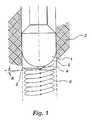
- FIG. 1 is a schematic conceptual illustration of a drill bit rotating and movingdownward into a subterranean formation as a borehole is cut therein;
- FIG. 2 is a part cross-sectional/part side view of a first embodiment of a drillbit in accordance with the present invention;
- FIG. 3 is a part cross-sectional/part side view of a second embodiment of adrill bit in accordance with the present invention;
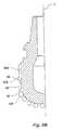
- FIG. 4 is a part cross-sectional/part side view of a third embodiment of a drillbit in accordance with the present invention;
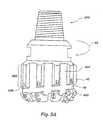
- FIG. 5A is a side view of a fourth embodiment of a drill bit in accordancewith the present invention;
- FIG. 5B is a partial cross-sectional view of the drill bit shown in FIG. 5A;
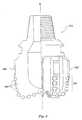
- FIG. 6 is a schematic view of a fifth embodiment of a drill bit in accordancewith the present invention;
- FIG. 7 is a partial cross-sectional view of a sixth embodiment of a drill bit inaccordance with the present invention;
- FIG. 8 is a partial cross-sectional, view of a seventh embodiment of a drill bitin accordance with the present invention;
- FIG. 9 is a partial cross-sectional view of an eighth embodiment of a drill bitin accordance with the present invention;
- FIG. 10 is a side view of a ninth embodiment of a drill bit in accordance withthe present invention;
- FIG. 11 is a schematic view from the underside of the bit, depicting a helicalmulti-lead gage definition region or portion according to the present invention; and
- FIG. 12 is a side elevation of a tri-cone bit employing a gage definitionregion.
- As conceptually shown in FIG. 1, since a drill bit I is rotating and movingdownward into the
formation 2 as theborehole 3 is cut, the cutting path followed byanindividual cutter 4 on the surface 5 of thebit 1 follows a helical path downwardlyspiralling at an angle A relative to the horizontal, the path being illustrated bysolidline 6 extending down theborehole 3 into theformation 2. For example, abit 1having acutter 4 rotating in a radius of six inches, at a drilling rate of ten feet perminute, and a rotational speed of 50 revolutions per minute results in thehelical path 6 having an angle A of inclination relative to horizontal of approximately 4°. Whilebit 1 is shown having asingle cutter 4 affixed on the exterior surface 5 of thedrill bit 1, it should be understood that a bit typically employs numerous cutters. For thepurposes of illustrating thehelical path 6 followed by anindividual cutter 4 onbit 1,only asingle cutter 4 has been illustrated. - FIG. 2 shows a
rotary drill bit 10 having a generallycylindrical bit body 11 inaccordance with the present invention. Thedrill bit 10 has a connectingstructure 12at a proximal or trailingend 14 for attachment to a drill string by a collar or othermethods as known in the art. At a distal or leadingend 16 of thedrill bit 10 is theface 18 to which a plurality offace cutters 20 may be attached. What hasconventionally been called the gage of thebit 10 extends upwardly from theface 18asgage area 22, which ultimately defines the diameter of the hole to be drilled withsuch abit 10. - The
bit 10 may also include a plurality ofjunk slots 24 longitudinallyextending from theface 18 of thebit body 11 through thegage area 22. Thejunkslots 24 allow drilling fluid jetted fromnozzle ports 25 and cuttings generated duringthe drilling process to flow upwardly between thebit 10 and the wellbore wall. Asshown, thesejunk slots 24 may communicate withface passages 21 adjacent thecutters 20 such that formation cuttings may flow from thecutters 20 viaface passages 21 directly into thejunk slots 24, carried by drilling fluid emanating from nozzles inthe bit face. - According to the present invention, the
gage area 22 is comprised of agagedefinition region 30 including a plurality of cuttingelements 26 and aslick gageregion 32 including a plurality ofgage pads 28. In this embodiment, the cuttingelements 26 of thegage definition region 30 are helically arranged around theperimeter of thegage area 22. The cutting edges 27 of the cuttingelements 26gradually increase in radial distance from the centerline CL of thebit 10, thosecuttingedges 27 nearest the leadingend 16 of thebit 10 being closest to thebit 10centerline.Cutting elements 26 may comprise PDC, TSP, cubic boron nitride,natural diamond, synthetic diamond grit (in the matrix or in impregnated cutterform), or any other suitable materials known in the art. Thegage definition region 30 reduces the stress that would otherwise be placed on the outermost face cutters 20'as conventionally employed as a "gage" cutter by gradually enlarging the wellbore to its final or gage diameter from the diameter cut by theface cutters 20. Thus, evenradially outermost face cutters 20' undergo primarily normal forces, rather than thedestructive tangential forces experienced when conventional cutter exposures anddepths of cut are used with cutters at the periphery of the bit face to define the gagediameter of the bit. Stated another way, the helical configuration of thegagedefinition region 30 provides necessary cutter redundancy to gradually andincrementally expand the diameter of the wellbore to gage diameter from an initialdiameter and by cutters on the bit face rather than taking relatively large cuts with theoutermost face cutters 20'. As illustrated, thegage definition region 30 includesseveral rows of cuttingelements 26 withslots 36 similarly helically interposedbetween each row of cuttingelements 26. Adjacent to and above thegage definitionregion 30, theslick gage region 32 includes a plurality of substantiallyrectangulargage pads 28 that may also be comprised of other shapes such as circles, triangles andthe like, as known in the art.Pads 28 may be comprised of tungsten carbide insertsor other abrasion- and erosion-resistant materials known in the art. Thepads 28extend from the bit centerline a distance slightly smaller than the radial distance cutby cutting elements 26' extending the greatest radius from centerline CL. - As illustrated, both the
gage pads 28 and the cuttingelements 26 extend fromthebit body 11 of thebit 10 such that thegage definition portion 30 continues to cutas thegage pads 28 wear. Moreover, the cuttingelements 26 provide cutting actionuntil they wear to such extent that an undergage wellbore is being cut, at which pointthe bit may be tripped. Thus, as thebit 10 is rotated into a formation, thegagedefinition region 30 actively assists in cutting and maintaining the gage diameter ofthe borehole such that theslick gage region 32 is always afforded adequate clearanceand is thus far less likely to impede the ROP of thedrill bit 10. - Another advantage of employing a gage definition region with cuttingelements arranged according to the invention is to compensate for wear of radiallyoutermost face cutters 20', so that as such face cutters 20' are worn, the
cutters 26and 26' ofgage definition region 30 become engaged with the formation being drilledand so maintain a desired minimum gage diameter of the wellbore. In such a design,the radially outermost cutters 20' may be placed so that, as they wear, the radiallyoutermost cutters 26' of the gage definition region are first to engage the wellbore sidewall, withother cutters 26 therebelow engaging the sidewall as further wearoccurs in cutters 20' and cutters 26' begin to wear. - As illustrated in the following embodiments, the gage area of the drill bit mayinclude many variations and combinations thereof.For example, in FIG. 3, the gage area of the
drill bit 210 may comprisein its entirety agage definition region 230 including a plurality of cuttingelements 226 helically arranged about the perimeter of thegage definition region 230 tosubstantially match the helical path or range of paths (depending on rotational speedand ROP) of the cuttingelements 226 as they are rotated into a formation. Asshown, the cuttingelements 226 are larger than those depicted in FIG. 2, as are theslots 236. The helical arrangement of the cuttingelements 226 may be a constantpitch helix as shown or a variable-pitch helix such that the angle of the helix increasesfrom one end of thegage definition region 230 to the other. Such a helicalarrangement of cuttingelements 226 can thus accommodate different rotationalspeeds and ROPs of thedrill bit 10. A helical arrangement in an oppositely-variable(decreasing) pitch configuration could also be beneficial. While helically arrangedcuttingelements 226 may be preferred, the important feature of any arrangement ofcutters is that the cutting elements provide sufficient overlap in their respective pathsand be of sufficiently-close radial placement (as defined at their radially outermostedges) to nibble away at the formation until the gage diameter is reached. Thus, anyconfiguration of a plurality of rotationally overlapping cutters arranged to take aseries of small-depth cuts outwardly from the face of the bit would provide thedesired gradually expanding gage diameter effect. It should be noted that in thisembodiment, thedrill bit 210 also includes a plurality offace cutters 38 positionedaround theface 218 of thebit 210. The cuttingelements 226 ongage definitionregion 330 assist theface cutters 38 by incrementally cutting the desired boreholegage diameter and thus reduce the tangential loading experienced by the outermostface cutters 38' to an acceptable level. - FIG. 4 is similar to the
bit 10 depicted in FIG. 2 but illustrates a moreconventional-looking cutter configuration. In this preferred embodiment, thecutters 326 of thegage definition region 330 are configured as what conventionally aretermed "gage cutters." That is, they each have a flat side 327 which, in the art, would be used to precisely cut the gage diameter of the wellbore. In thisembodiment, however, the flatsided cutters 326 are radially spaced from thebit 310centerline so that their flat sides gradually increase in radial distance from thebit 310centerline from each cutter to its immediately following cutter until the desired gagediameter is achieved. As further illustrated, the slick gage region may be comprisedof a plurality of longitudinally-spacedgage pads 328. Additionally, the cuttingelements 326 of thegage definition region 330 are positioned between thegage pads 328 and the face cutters 320. Typically, thegage pads 328 will be comprised of aless abrasion-resistant material than the cuttingelements 326, so that cuttingelements 326 will always cut a larger diameter wellbore than the diameter defined bygagepads 328. - As shown in FIGS. 5A and 5B, gage definition elements (cutters) 426 may beplaced along a helix relative to the longitudinal axis L (see FIG. 5B) of the
bit 410 asshown in FIG- 5A such that a cuttingface 42 of each cuttingelement 426 issomewhat radially oriented and faces substantially toward the direction of rotation ofthe bit, indicated byarrow 44. As shown in FIG. 5B, the cuttingelement 426 maybe partially cylindrical, with a flat orlinear edge portion 46 similar to edge 40 ofgage cutter 438 therebelow. The cuttingelements 426 may be oriented at any backrake angle between 0° (circumferentially), as shown in FIG. 3, and 90° (radially), asshown in FIG. 5A. Further, the cuttingelements 426 may be oriented at any suitableside rake angle relative to the longitudinal axis of thebit 410. Thegage 422 of thedrill bit 410 may also include a substantiallyhelical slot 48, as well asjunk slots 424or any combination thereof, to allow cuttings and drilling fluid to pass through thegage region 422 of thedrill bit 410. It should also be noted thatcutters 426 may betilted into or away from the helix angle about their horizontal axes, instead of merelyhaving their cutting faces 42 oriented parallel to the longitudinal bit axis.Additionally, the cuttingelements 426 may have a rake angle adjusted according tothe computed effective rake angle for a given ROP of thebit 410, the effective rakeangle being determined by adding the angle of the helical path of thecutter 426 intothe formation relative to the horizontal to the apparent rake angle of thecutter 426.For example, if the cuttingsurface 42 ofcutter 426 has an apparent angle ofinclination relative to a radially extending plane through the cuttingface 42 of approximately 86° (i.e., 4° negative rake) and the helical path of thecutter 426 hasan angle of inclination relative to horizontal of 4°, then the cuttingface 42 has aneffective angle of inclination, or effective rake, of precisely 90° and will be neithernegatively nor positively raked. - It should also be recogaized that the radial position of the
cutter 426 relativeto the centerline of the bit is determinative as to the effective rake angle. That is, thecloser a cutter is positioned to the bit center, the greater the angle of inclination of thehelical path relative to the horizontal for a given rotational speed and ROP, and thegreater the apparent negative rake of the cutter must be to obtain an effectively morepositive rake angle. - In FIG. 6,
gage 522 may comprise twogage definition regions elements 50 and cuttingelements 51. The broachedcutting elements 50 are basically individual or freestandingnatural orsynthetic diamonds 49 arranged in a row and inset and securedinto aninsert 47 possibly made of tungsten carbide, brass, tungsten or steel. Inaddition, the radially extendinggage portions 534 may be helically configured, in thisexemplary embodiment a relatively steep helix, about the perimeter of thegage 522defining similarly helically configured, interveningjunk slots 524. The broachedcutting elements 50 are preferably angled and set relative to the exterior surfaces 62of thegage pads 528 to form an inward frustoconical taper along thegage definitionregion 530 toward theleading end 516 of thebit 510, thus increasing the gagediameter of thebit 510 from the radiallyoutermost face cutters 538 to thegage pads 528. As will be understood by those skilled in the art, such an angledgage definitionregion 530 could be incorporated into any of the embodiments described herein. - As further illustrated in FIG. 7, a
bit 610 may include multiplegage definitionregions slick gage regions multistagecutting bit 610. Accordingly, during drilling, theface cutters 636 cut thewellbore to a substantial percentage of the gage diameter. The firstgage definitionregion 630 then removes a relatively small amount of the wall of the wellbore,through which the firstslick gage region 632 can pass. The secondgage definitionregion 631 engages and removes a relatively small amount of the formation until thesecond slick gage region can pass therethrough- Such an arrangement may be particularly suitable for drilling long, linear wellbore intervals through hardformations while minimizing vibration and whirl tendencies of the bit. If desired, itis possible to configure the entire bit crown to comprise one elongated gage definitionregion or a series of progressively larger gage definition regions extending from avery small group of nose cutters at the centerline of the bit, omitting the traditionalbit "face" and resulting in a tapered, generally conical bit crown. Slick gage regionsmay be located between gage definition regions of a series, if desired, or recessesmay be employed therebetween, or both slick gage and recessed regions used. - Likewise, as illustrated in FIG. 8, a
gage definition region 642 of abit 640may be followed by agage recess 644 which is followed by aslick gage region 646.Such a gage configuration may be particularly desirable for steering drill bits wherethe fulcrum of the bit is effectively moved to theslick gage region 646. - As further illustrated in FIG. 9, the portion of the
bit 650 conventionallytermed a "gage" is not included. Accordingly, thegage definition region 652provides the only contact above the bit face between the wellbore wall and thebit 650during drilling. Such abit 650 would be highly steerable and particularly suitable forshort-radius directional drilling, as the bit could effectively pivot about thecrown 654. - As illustrated in FIG. 10, cutting elements 70-78 are helically arranged aroundthe
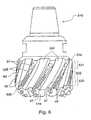
gage definition portion 92 of thebit 90 such that thegage definition portion 92 issubstantially a cutting gage without conventional gage pads thereon. In addition, ascan be observed by examiningcutting elements element 72 whichis closer to theleading end 94 of thebit 90 is radially inset into theblade 96substantially more than the cuttingelement 77. While not as easily seen betweenadjacent cutting elements, those closer to theleading end 94 are inset slightly moreinto their respective blade than the next adjacent (following) cutting element. Forexample, cuttingelement 74 radially protrudes from itsblade 97 slightly more thancuttingelement 73 from itsblade 98. Similarly, cuttingelement 75 radially extendsfrom itsblade 99 slightly more than cutting element 101, and so on. Such anarrangement of cutting elements 70-78 in effect provides a varying diameter helix, orspiral, in which each successive cutting element in the helix cuts a little more fromthe formation than its preceding cutting element, thus "nibbling" the formation material and minimizing loading on each of the cutters. The amount of formation"seen" by each cutting element can be controlled, depending on the inset of eachcutting element relative to the preceding cutting element in the helix. Accordingly,the forces and stresses applied to each cutting element can also be controlled bycontrolling the exposure of each cutting element to the formation upon rotation of thebit 90. - While insetting each cutting element a different distance into the bit is oneway of achieving a varying diameter helix of cutting elements, the same effect can beachieved by varying the diameter of the exterior surface of the blades of the bit. It isalso contemplated, as shown in FIG. 2, that varying sizes of cutting elements couldalso achieve the same diametric effect by following smaller cutting elements bysuccessively larger ones, or that equal-diameter cutting elements may have flatstrimmed to different sizes to vary the diameter of cut. This approach, effected afterthe cutters are mounted on the bit, could achieve very precise dimensional control ofthe various portions of the gage definition region according to the present invention.In addition, as previously mentioned, while the cutting elements are shown in varioushelical arrangements, any overlapping relationship of the cutting elements uponrotation of the bit could produce the desired gradual cutting action of the gagedefinition region.
- In addition to the cutting elements 70-78 being helically arranged, it may alsobe desirable to provide helically configured
junk slots 122 in addition to conventionalvertical junk slots 124. These additional helically configuredjunk slots 122 will aidin removing debris from around thebit 90 and from theface 93 of each cutter 70-78,and allow a greater volume of drilling fluid to circulate around thebit 90 and thusenhance cooling of the cutters 70-78. - As previously noted, the gage definition region may be configured as aplurality of redundant helices, with two or three cutting elements circumferentiallyspaced about the bit at a smaller entry diameter slightly larger than the face diameter,each of the two or three circumferentially-spaced cutting elements being followed bya discrete series of cutters. Each helical series of cutters defines ever-largerdiameters, cutter by cutter, until gage diameter is reached. Alternatively, a pluralityof cutters may be placed to cut each incrementally larger diameter, although not configured in a helix. Ideally, and regardless of whether a helical cutter pattern isemployed, there will be cutter redundancy at each incremental diameter. FIG. 11schematically illustrates such redundancy from the underside of the bit, depictingthree
cutters 726 at each incremental diameter, but placed on one of three differenthelices, as shown. The width W of the gage definition region GDR has beenexaggerated for clarity. Thus, it can be readily appreciated how the face diameterFD cut by the bit face is enlarged to the gage diameter GD of the wellbore in acontrolled, non-destructive manner according to the invention. - In general, there are two cutter overlap configurations considered by thepresent invention. First, cutters in the gage definition region of the bit experience adegree of longitudinal overlap such that each cutter cuts a small depth of materialfrom the bottom of the wellbore radially outboard of the outermost face cutter. Thismay be accomplished by the helical configuration of cutters around the gage orotherwise spacing the cutters to achieve the desired longitudinal overlap. Second, thecutters in the gage definition region of the bit provide depth of cut overlap such thateach cutter takes a slightly deeper radial cut into the formation than a precedingcutter. This is accomplished by varying the radial distance of the cutting edge of thecutters from the centerline of the bit so that each cutter effectively nibbles at theformation rather than taking large cuts as is the case with so-called gage cutters ofprior art drill bits.
- While the various gage definition regions herein described have beenillustrated with respect to a rotary drag bit, it will be appreciated by those skilled inthe art, however, that the arrangement of cutters according to the present inventionmay have equal utility on a coring bit or a tri-cone roller bit. FIG. 12 depicts anexemplary
tri-cone roller bit 700.Gage areas 702 may be provided with cuttingelements 726 of gradually increasing size, orlegs 704 ofbit 700 may be formed withexterior surfaces disposed at a slight increasing angle to the bit centerline (shown),and cuttingelements 726 of consistent size employed. Further, cuttingelements 726may be set into the material oflegs 704 at varying depths to achieve a graduallyincreasing diameter of cut. Alternatively, preformed inserts or other cutting element-carryingstructures may be affixed in recesses on the exteriors oflegs 704, orotherwise secured to the exterior surfaces thereof. Those skilled in the art will also appreciate that various combinations and obvious modifications of the preferredembodiments may be made.
Claims (20)
- A rotary drill bit for drilling wellbore in a subterranean formation, comprising:a bit body having a leading end with a face and a trailing end;a cutting structure mounted on said face and including a plurality of facecutters mounted on said face; andat least one gage definition region longitudinally extending from proximatesaid plurality of face cutters toward said trailing end, said at least one gage definitionregion defining a larger diameter at its trailing longitudinal extent than at its leadinglongitudinal extent and including a plurality of cutterscharacterised in that said plurality of cutters aredisclosed on said gage definition region to form atleast one variable-pitch helix arranged to substantially match a range of predictedhelical paths of cutters of said at least one gage definition region into a formationattributable to rotation and longitudinal advance of said drill bit in drilling of saidwellbore.
- The drill bit of claim 1, wherein each cutter of said plurality of cutters of saidat least one gage definition region each defines a cutting edge, wherein cutting edgesof cutters closer to said trailing end are positioned a greater radial distance from alongitudinal axis of said bit than cutting edges of cutters closer to said leading end.
- The drill bit of claim 1, wherein said plurality of cutters of said at least onegage definition region include a plurality of cutting edges defining a longitudinally-extendingperimeter, said perimeter substantially forming a frustoconical taper.
- The drill bit of claim 1, wherein said plurality of face cutters is positioned tosubstantially cut said wellbore to a first diameter and said plurality of cutters on saidat least one gage definition region are positioned to relatively gradually enlarge thewellbore first diameter.
- The drill bit of claim 1, wherein said at least one gage definition region lies atan acute angle relative to a longitudinal axis of said bit.
- The drill bit of claim 1, wherein a radius of said at least one varaible-pitchhelix, taken from a centerline of said bit, increases from said leading end toward saidtrailing end.
- The drill bit of claim 1, wherein said cutters of said plurality of cutters of saidat least one gage definition region each includes a cutting face oriented at a selectedrake angle relative to said bit body to produce a desired effective rake angle uponrotation of said drill bit into a formation at a given rotational speed and rate ofpenetration.
- The drill bit of claim 7, wherein said selected rake angle is between 0° and90°.
- The drill bit of claim 1, wherein said at least one gage definition region furtherincludes a plurality of junk slots substantially longitudinally extending from said faceof said bit body through at least a portion of said at least one gage definition region.
- The drill bit of claim 9, wherein said plurality of junk slots and said pluralityof cutters are helically arranged about said at least one gage definition region.
- The drill bit of claim 1, wherein said cutters of said plurality on said at leastone gage definition region are comprised of at least one material selected from thegroup comprising: PDC, TSP, cubic boron nitride, natural diamond, and syntheticdiamond grit.
- The drill bit of claim 1, further including at least one slick gage portion in saidat least one gage definition region.
- The drill bit of claim 12, wherein said at least one slick gage portion is at leastpartially formed of a less abrasion resistant material than said at least one gagedefinition region cutters.
- The drill bit of claim 13, wherein said at least one slick gage portion includes aplurality of wear inserts.
- The drill bit of claim 1, further including an additional portion of said bit bodyabove said at least one gage definition region and of lesser diameter than said trailinglongitudinal extent of said at least one gage definition region.
- The drill bit of claim 1, wherein said at least one gage definition regionincludes a plurality of longitudinally-separated cutting gage portions.
- The drill bit of claim 1, wherein said at least one gage definition regionincludes at least one broached gage portion.
- The drill bit of claim 1, further including at least one slick gage regioninterposed longitudinally between two gage definition regions.
- The drill bit of claim 1, further including at least one circumferentially-extendingrecess interposed longitudinally between two gage definition regions.
- The drill bit of claim 1, wherein said rotary drill bit is a rolling cone bit.
Applications Claiming Priority (2)
| Application Number | Priority Date | Filing Date | Title |
|---|---|---|---|
| US832051 | 1997-04-02 | ||
| US08/832,051US6123160A (en) | 1997-04-02 | 1997-04-02 | Drill bit with gage definition region |
Publications (3)
| Publication Number | Publication Date |
|---|---|
| EP0869256A2 EP0869256A2 (en) | 1998-10-07 |
| EP0869256A3 EP0869256A3 (en) | 2002-04-17 |
| EP0869256B1true EP0869256B1 (en) | 2004-06-23 |
Family
ID=25260535
Family Applications (1)
| Application Number | Title | Priority Date | Filing Date |
|---|---|---|---|
| EP98302621AExpired - LifetimeEP0869256B1 (en) | 1997-04-02 | 1998-04-02 | Rotary drill bit with gage definition region, method of manufacturing such a drill bit and method of drilling a subterranean formation |
Country Status (2)
| Country | Link |
|---|---|
| US (1) | US6123160A (en) |
| EP (1) | EP0869256B1 (en) |
Cited By (1)
| Publication number | Priority date | Publication date | Assignee | Title |
|---|---|---|---|---|
| WO2013166266A1 (en)* | 2012-05-03 | 2013-11-07 | Smith International Inc. | Gage cutter protection for drilling bits |
Families Citing this family (72)
| Publication number | Priority date | Publication date | Assignee | Title |
|---|---|---|---|---|
| US6206117B1 (en)* | 1997-04-02 | 2001-03-27 | Baker Hughes Incorporated | Drilling structure with non-axial gage |
| US6253863B1 (en)* | 1999-08-05 | 2001-07-03 | Smith International, Inc. | Side cutting gage pad improving stabilization and borehole integrity |
| US6684967B2 (en)* | 1999-08-05 | 2004-02-03 | Smith International, Inc. | Side cutting gage pad improving stabilization and borehole integrity |
| US6302223B1 (en) | 1999-10-06 | 2001-10-16 | Baker Hughes Incorporated | Rotary drag bit with enhanced hydraulic and stabilization characteristics |
| US6575256B1 (en)* | 2000-01-11 | 2003-06-10 | Baker Hughes Incorporated | Drill bit with lateral movement mitigation and method of subterranean drilling |
| US6688410B1 (en)* | 2000-06-07 | 2004-02-10 | Smith International, Inc. | Hydro-lifter rock bit with PDC inserts |
| US6427792B1 (en)* | 2000-07-06 | 2002-08-06 | Camco International (Uk) Limited | Active gauge cutting structure for earth boring drill bits |
| US6474425B1 (en)* | 2000-07-19 | 2002-11-05 | Smith International, Inc. | Asymmetric diamond impregnated drill bit |
| US6349780B1 (en)* | 2000-08-11 | 2002-02-26 | Baker Hughes Incorporated | Drill bit with selectively-aggressive gage pads |
| US7451836B2 (en) | 2001-08-08 | 2008-11-18 | Smith International, Inc. | Advanced expandable reaming tool |
| US6810971B1 (en) | 2002-02-08 | 2004-11-02 | Hard Rock Drilling & Fabrication, L.L.C. | Steerable horizontal subterranean drill bit |
| US6827159B2 (en) | 2002-02-08 | 2004-12-07 | Hard Rock Drilling & Fabrication, L.L.C. | Steerable horizontal subterranean drill bit having an offset drilling fluid seal |
| US6810973B2 (en) | 2002-02-08 | 2004-11-02 | Hard Rock Drilling & Fabrication, L.L.C. | Steerable horizontal subterranean drill bit having offset cutting tooth paths |
| US6810972B2 (en) | 2002-02-08 | 2004-11-02 | Hard Rock Drilling & Fabrication, L.L.C. | Steerable horizontal subterranean drill bit having a one bolt attachment system |
| US6814168B2 (en) | 2002-02-08 | 2004-11-09 | Hard Rock Drilling & Fabrication, L.L.C. | Steerable horizontal subterranean drill bit having elevated wear protector receptacles |
| US7299887B2 (en)* | 2002-04-23 | 2007-11-27 | Kingdream Public Ltd. Co. | Roller bit with a journal pin offset from the central axis thereof |
| US6834733B1 (en)* | 2002-09-04 | 2004-12-28 | Varel International, Ltd. | Spiral wave bladed drag bit |
| US7395882B2 (en) | 2004-02-19 | 2008-07-08 | Baker Hughes Incorporated | Casing and liner drilling bits |
| BRPI0416910B1 (en)* | 2003-11-28 | 2015-11-03 | Shell Int Research | method of removing a body of material, and drill bit to drill a borehole in an earth formation |
| US7624818B2 (en) | 2004-02-19 | 2009-12-01 | Baker Hughes Incorporated | Earth boring drill bits with casing component drill out capability and methods of use |
| US7954570B2 (en) | 2004-02-19 | 2011-06-07 | Baker Hughes Incorporated | Cutting elements configured for casing component drillout and earth boring drill bits including same |
| US7798256B2 (en)* | 2005-03-03 | 2010-09-21 | Smith International, Inc. | Fixed cutter drill bit for abrasive applications |
| US7860693B2 (en)* | 2005-08-08 | 2010-12-28 | Halliburton Energy Services, Inc. | Methods and systems for designing and/or selecting drilling equipment using predictions of rotary drill bit walk |
| CA2625012C (en) | 2005-08-08 | 2016-05-03 | Halliburton Energy Services, Inc. | Methods and systems for design and/or selection of drilling equipment based on wellbore drilling simulations |
| US20070261890A1 (en)* | 2006-05-10 | 2007-11-15 | Smith International, Inc. | Fixed Cutter Bit With Centrally Positioned Backup Cutter Elements |
| US7621351B2 (en) | 2006-05-15 | 2009-11-24 | Baker Hughes Incorporated | Reaming tool suitable for running on casing or liner |
| US20070278014A1 (en)* | 2006-05-30 | 2007-12-06 | Smith International, Inc. | Drill bit with plural set and single set blade configuration |
| GB2453875C (en)* | 2006-10-02 | 2009-09-16 | Smith International | Drill bits with dropping tendencies |
| US8172010B2 (en)* | 2007-02-02 | 2012-05-08 | Halliburton Energy Services, Inc. | Rotary drill bit steerable system and method |
| CN101688434B (en) | 2007-05-30 | 2013-06-19 | 霍利贝顿能源服务公司 | Rotary drill bit with gage pads having improved steerability and reduced wear |
| US7703557B2 (en)* | 2007-06-11 | 2010-04-27 | Smith International, Inc. | Fixed cutter bit with backup cutter elements on primary blades |
| US7954571B2 (en)* | 2007-10-02 | 2011-06-07 | Baker Hughes Incorporated | Cutting structures for casing component drillout and earth-boring drill bits including same |
| US20090145667A1 (en)* | 2007-12-05 | 2009-06-11 | Smith International, Inc. | Active stabilization during cutting for hole opening tools |
| US9016407B2 (en) | 2007-12-07 | 2015-04-28 | Smith International, Inc. | Drill bit cutting structure and methods to maximize depth-of-cut for weight on bit applied |
| AU2008338627B2 (en) | 2007-12-14 | 2014-04-10 | Halliburton Energy Services, Inc. | Methods and systems to predict rotary drill bit walk and to design rotary drill bits and other downhole tools |
| WO2009146078A1 (en) | 2008-04-01 | 2009-12-03 | Smith International, Inc. | Fixed cutter bit with backup cutter elements on secondary blades |
| GB2460096B (en) | 2008-06-27 | 2010-04-07 | Wajid Rasheed | Expansion and calliper tool |
| US7849940B2 (en)* | 2008-06-27 | 2010-12-14 | Omni Ip Ltd. | Drill bit having the ability to drill vertically and laterally |
| US8327951B2 (en)* | 2008-06-27 | 2012-12-11 | Omni Ip Ltd. | Drill bit having functional articulation to drill boreholes in earth formations in all directions |
| CN101382045A (en)* | 2008-07-30 | 2009-03-11 | 江汉石油钻头股份有限公司 | Three-cone bit for horizontal well and hard formation well |
| WO2011038383A2 (en) | 2009-09-28 | 2011-03-31 | Bake Hughes Incorporated | Earth-boring tools, methods of making earth-boring tools and methods of drilling with earth-boring tools |
| US9109412B2 (en) | 2010-06-04 | 2015-08-18 | Dover Bmcs Acquisition Corporation | Rotational drill bits and drilling apparatuses including the same |
| US8584777B2 (en) | 2010-06-04 | 2013-11-19 | Dover Bmcs Acquisition Corporation | Rotational drill bits and drilling apparatuses including the same |
| US8905162B2 (en) | 2010-08-17 | 2014-12-09 | Trendon Ip Inc. | High efficiency hydraulic drill bit |
| US9080400B1 (en) | 2010-11-24 | 2015-07-14 | Dover Bmcs Acquisition Corporation | Rotational drill bits and drilling apparatuses including the same |
| RU2459064C1 (en)* | 2011-04-12 | 2012-08-20 | Николай Митрофанович Панин | Drilling bit |
| RU2481459C1 (en)* | 2012-01-13 | 2013-05-10 | Николай Митрофанович Панин | Rock-destroying tool (versions) |
| GB2506901B (en)* | 2012-10-11 | 2019-10-23 | Halliburton Energy Services Inc | Drill bit apparatus to control torque on bit |
| US9255450B2 (en) | 2013-04-17 | 2016-02-09 | Baker Hughes Incorporated | Drill bit with self-adjusting pads |
| CN103362444B (en)* | 2013-07-24 | 2016-10-26 | 中国地质大学(武汉) | A kind of cutting-grinding fin type oil/gas drilling drill bit |
| US9739094B2 (en) | 2013-09-06 | 2017-08-22 | Baker Hughes Incorporated | Reamer blades exhibiting at least one of enhanced gage cutting element backrakes and exposures and reamers so equipped |
| GB2520998B (en) | 2013-12-06 | 2016-06-29 | Schlumberger Holdings | Expandable Reamer |
| GB2528458A (en) | 2014-07-21 | 2016-01-27 | Schlumberger Holdings | Reamer |
| GB2528454A (en) | 2014-07-21 | 2016-01-27 | Schlumberger Holdings | Reamer |
| GB2528457B (en) | 2014-07-21 | 2018-10-10 | Schlumberger Holdings | Reamer |
| WO2016014283A1 (en) | 2014-07-21 | 2016-01-28 | Schlumberger Canada Limited | Reamer |
| GB2528456A (en) | 2014-07-21 | 2016-01-27 | Schlumberger Holdings | Reamer |
| GB2528459B (en) | 2014-07-21 | 2018-10-31 | Schlumberger Holdings | Reamer |
| CN104329030B (en)* | 2014-10-24 | 2016-09-21 | 宜春学院 | A kind of six point location indent three wings PDC borehole bit structure and radial-protecting methods thereof |
| CN104481413B (en)* | 2014-11-26 | 2016-12-07 | 胜利油田盛辉石油技术开发有限责任公司 | A kind of revolving cutting bit of rig |
| US10041305B2 (en) | 2015-09-11 | 2018-08-07 | Baker Hughes Incorporated | Actively controlled self-adjusting bits and related systems and methods |
| US10214968B2 (en) | 2015-12-02 | 2019-02-26 | Baker Hughes Incorporated | Earth-boring tools including selectively actuatable cutting elements and related methods |
| US10066444B2 (en) | 2015-12-02 | 2018-09-04 | Baker Hughes Incorporated | Earth-boring tools including selectively actuatable cutting elements and related methods |
| US10273759B2 (en) | 2015-12-17 | 2019-04-30 | Baker Hughes Incorporated | Self-adjusting earth-boring tools and related systems and methods |
| US10494875B2 (en)* | 2017-01-13 | 2019-12-03 | Baker Hughes, A Ge Company, Llc | Impregnated drill bit including a planar blade profile along drill bit face |
| US10633929B2 (en) | 2017-07-28 | 2020-04-28 | Baker Hughes, A Ge Company, Llc | Self-adjusting earth-boring tools and related systems |
| WO2019068005A1 (en)* | 2017-09-29 | 2019-04-04 | Baker Hughes, A Ge Company, Llc | Earth-boring tools having a gauge insert configured for reduced bit walk and method of drilling with same |
| WO2019094975A1 (en) | 2017-11-13 | 2019-05-16 | Louisiana-Pacific Corporation | Engineered fence panels and process |
| US10557318B2 (en)* | 2017-11-14 | 2020-02-11 | Baker Hughes, A Ge Company, Llc | Earth-boring tools having multiple gage pad lengths and related methods |
| US11208848B1 (en)* | 2018-07-19 | 2021-12-28 | Klear Bit Technologies LLC | Cutting element for casing bit |
| WO2020180330A1 (en)* | 2019-03-07 | 2020-09-10 | Halliburton Energy Services, Inc. | Shaped cutter arrangements |
| CN111188577A (en)* | 2020-03-20 | 2020-05-22 | 宜昌神达石油机械有限公司 | A Pulse Speed-Up PDC Drill Bit |
Family Cites Families (48)
| Publication number | Priority date | Publication date | Assignee | Title |
|---|---|---|---|---|
| US1084871A (en)* | 1912-05-27 | 1914-01-20 | Joseph Tuck | Cutter-head for mining-machines. |
| US1547459A (en)* | 1923-12-22 | 1925-07-28 | George A Stafford | Drill |
| US1701427A (en)* | 1927-02-23 | 1929-02-05 | Bert Russell | Rotary drilling and reaming tool organization |
| US1907154A (en)* | 1932-05-23 | 1933-05-02 | William J Mitchell | Core drill |
| US2738167A (en)* | 1953-04-06 | 1956-03-13 | Jr Edward B Williams | Combined reamer and core bit |
| US2838286A (en)* | 1956-04-19 | 1958-06-10 | Christensen Diamond Prod Co | Rotary drill bit |
| US3135341A (en)* | 1960-10-04 | 1964-06-02 | Christensen Diamond Prod Co | Diamond drill bits |
| US3220497A (en)* | 1963-08-26 | 1965-11-30 | Christensen Diamond Prod Co | Rotary drag bit |
| BE701391A (en)* | 1966-07-15 | 1968-01-15 | ||
| US3367430A (en)* | 1966-08-24 | 1968-02-06 | Christensen Diamond Prod Co | Combination drill and reamer bit |
| US3825083A (en)* | 1972-02-02 | 1974-07-23 | Christensen Diamond Prod Co | Drill bit and stabilizer combination |
| US3945447A (en)* | 1974-09-16 | 1976-03-23 | Rapidex, Inc. | Boring apparatus |
| US4031974A (en)* | 1975-05-27 | 1977-06-28 | Rapidex, Inc. | Boring apparatus capable of boring straight holes |
| US4091884A (en)* | 1976-11-15 | 1978-05-30 | Smith International, Inc. | Rotary air percussion bit |
| US4098363A (en)* | 1977-04-25 | 1978-07-04 | Christensen, Inc. | Diamond drilling bit for soft and medium hard formations |
| US4351401A (en)* | 1978-06-08 | 1982-09-28 | Christensen, Inc. | Earth-boring drill bits |
| US4244432A (en)* | 1978-06-08 | 1981-01-13 | Christensen, Inc. | Earth-boring drill bits |
| US4234048A (en)* | 1978-06-12 | 1980-11-18 | Christensen, Inc. | Drill bits embodying impregnated segments |
| SU994677A1 (en)* | 1980-03-11 | 1983-02-07 | Ленинградский Ордена Ленина,Ордена Октябрьской Революции И Ордена Трудового Красного Знамени Горный Институт Им.Г.В.Плеханова | Drill bit |
| US4352400A (en)* | 1980-12-01 | 1982-10-05 | Christensen, Inc. | Drill bit |
| US4550790A (en)* | 1983-02-28 | 1985-11-05 | Norton Christensen, Inc. | Diamond rotating bit |
| US4515226A (en)* | 1983-03-07 | 1985-05-07 | Norton Christensen, Inc. | Tooth design to avoid shearing stresses |
| US4512426A (en)* | 1983-04-11 | 1985-04-23 | Christensen, Inc. | Rotating bits including a plurality of types of preferential cutting elements |
| US4515227A (en)* | 1983-04-27 | 1985-05-07 | Christensen, Inc. | Nozzle placement in a diamond rotating bit including a pilot bit |
| US4586574A (en)* | 1983-05-20 | 1986-05-06 | Norton Christensen, Inc. | Cutter configuration for a gage-to-shoulder transition and face pattern |
| US4552231A (en)* | 1983-09-06 | 1985-11-12 | Norton Christensen, Inc. | Rotating pilot core bit for use in highly fractured formations |
| DE3414206C1 (en)* | 1984-04-14 | 1985-02-21 | Norton Christensen, Inc., Salt Lake City, Utah | Rotary drill bit for deep drilling |
| GB8628168D0 (en)* | 1986-11-22 | 1986-12-31 | Nl Petroleum Prod | Rotary drill bits |
| US4848489A (en)* | 1987-03-26 | 1989-07-18 | Reed Tool Company | Drag drill bit having improved arrangement of cutting elements |
| US4869330A (en)* | 1988-01-20 | 1989-09-26 | Eastman Christensen Company | Apparatus for establishing hydraulic flow regime in drill bits |
| US5004057A (en)* | 1988-01-20 | 1991-04-02 | Eastman Christensen Company | Drill bit with improved steerability |
| US4981183A (en)* | 1988-07-06 | 1991-01-01 | Baker Hughes Incorporated | Apparatus for taking core samples |
| US4941538A (en)* | 1989-09-20 | 1990-07-17 | Hughes Tool Company | One-piece drill bit with improved gage design |
| US4986375A (en)* | 1989-12-04 | 1991-01-22 | Maher Thomas P | Device for facilitating drill bit retrieval |
| BE1003903A3 (en)* | 1989-12-19 | 1992-07-14 | Diamant Boart Stratabit Sa | Tool for drilling extend well. |
| US5178222A (en)* | 1991-07-11 | 1993-01-12 | Baker Hughes Incorporated | Drill bit having enhanced stability |
| US5163524A (en)* | 1991-10-31 | 1992-11-17 | Camco Drilling Group Ltd. | Rotary drill bits |
| US5467836A (en)* | 1992-01-31 | 1995-11-21 | Baker Hughes Incorporated | Fixed cutter bit with shear cutting gage |
| US5314033A (en)* | 1992-02-18 | 1994-05-24 | Baker Hughes Incorporated | Drill bit having combined positive and negative or neutral rake cutters |
| AU5850694A (en)* | 1992-12-23 | 1994-07-19 | Baroid Technology, Inc. | Drill bit having chip breaker polycrystalline diamond compact and hard metal insert at gauge surface |
| US5361859A (en)* | 1993-02-12 | 1994-11-08 | Baker Hughes Incorporated | Expandable gage bit for drilling and method of drilling |
| GB2278558B (en)* | 1993-06-03 | 1995-10-25 | Camco Drilling Group Ltd | Improvements in or relating to the manufacture of rotary drill bits |
| US5605198A (en)* | 1993-12-09 | 1997-02-25 | Baker Hughes Incorporated | Stress related placement of engineered superabrasive cutting elements on rotary drag bits |
| US5456328A (en)* | 1994-01-07 | 1995-10-10 | Dresser Industries, Inc. | Drill bit with improved rolling cutter tooth pattern |
| GB9420838D0 (en)* | 1994-10-15 | 1994-11-30 | Camco Drilling Group Ltd | Improvements in or relating to rotary drill bits |
| US5641027A (en)* | 1995-01-09 | 1997-06-24 | Utd Incorporated | Drilling system |
| US5495899A (en)* | 1995-04-28 | 1996-03-05 | Baker Hughes Incorporated | Reamer wing with balanced cutting loads |
| US5678644A (en)* | 1995-08-15 | 1997-10-21 | Diamond Products International, Inc. | Bi-center and bit method for enhancing stability |
- 1997
- 1997-04-02USUS08/832,051patent/US6123160A/ennot_activeExpired - Fee Related
- 1998
- 1998-04-02EPEP98302621Apatent/EP0869256B1/ennot_activeExpired - Lifetime
Cited By (3)
| Publication number | Priority date | Publication date | Assignee | Title |
|---|---|---|---|---|
| WO2013166266A1 (en)* | 2012-05-03 | 2013-11-07 | Smith International Inc. | Gage cutter protection for drilling bits |
| CN104364460A (en)* | 2012-05-03 | 2015-02-18 | 史密斯国际有限公司 | Gage cutter protection for drilling bits |
| US9464490B2 (en) | 2012-05-03 | 2016-10-11 | Smith International, Inc. | Gage cutter protection for drilling bits |
Also Published As
| Publication number | Publication date |
|---|---|
| EP0869256A3 (en) | 2002-04-17 |
| US6123160A (en) | 2000-09-26 |
| EP0869256A2 (en) | 1998-10-07 |
Similar Documents
| Publication | Publication Date | Title |
|---|---|---|
| EP0869256B1 (en) | Rotary drill bit with gage definition region, method of manufacturing such a drill bit and method of drilling a subterranean formation | |
| US10851594B2 (en) | Kerfing hybrid drill bit and other downhole cutting tools | |
| US9540884B2 (en) | Drill bit with continuously sharp edge cutting elements | |
| US6206117B1 (en) | Drilling structure with non-axial gage | |
| US9145740B2 (en) | Stabilizing members for fixed cutter drill bit | |
| US6672406B2 (en) | Multi-aggressiveness cuttting face on PDC cutters and method of drilling subterranean formations | |
| US5346025A (en) | Drill bit with improved insert cutter pattern and method of drilling | |
| US8020641B2 (en) | Drill bit with continuously sharp edge cutting elements | |
| US9016407B2 (en) | Drill bit cutting structure and methods to maximize depth-of-cut for weight on bit applied | |
| GB2326659A (en) | Rotary drill bits | |
| GB2438520A (en) | Drill bit | |
| US20100089661A1 (en) | Drill bit with continuously sharp edge cutting elements | |
| US7497281B2 (en) | Roller cone drill bits with enhanced cutting elements and cutting structures | |
| US6006845A (en) | Rotary drill bits for directional drilling employing tandem gage pad arrangement with reaming capability | |
| US20100089658A1 (en) | Drill bit with continuously sharp edge cutting elements | |
| EP3363988B1 (en) | Impregnated drill bit including a planar blade profile along drill bit face | |
| US6112836A (en) | Rotary drill bits employing tandem gage pad arrangement | |
| US12264542B2 (en) | Fixed cutter drill bits and cutter element arrangements for same |
Legal Events
| Date | Code | Title | Description |
|---|---|---|---|
| PUAI | Public reference made under article 153(3) epc to a published international application that has entered the european phase | Free format text:ORIGINAL CODE: 0009012 | |
| AK | Designated contracting states | Kind code of ref document:A2 Designated state(s):AT BE CH CY DE DK ES FI FR GB GR IE IT LI LU MC NL PT SE Kind code of ref document:A2 Designated state(s):BE GB IT | |
| PUAL | Search report despatched | Free format text:ORIGINAL CODE: 0009013 | |
| AK | Designated contracting states | Kind code of ref document:A3 Designated state(s):AT BE CH CY DE DK ES FI FR GB GR IE IT LI LU MC NL PT SE | |
| AX | Request for extension of the european patent | Free format text:AL;LT;LV;MK;RO;SI | |
| 17P | Request for examination filed | Effective date:20020618 | |
| 17Q | First examination report despatched | Effective date:20020809 | |
| AKX | Designation fees paid | Free format text:BE GB IT | |
| REG | Reference to a national code | Ref country code:DE Ref legal event code:8566 | |
| GRAP | Despatch of communication of intention to grant a patent | Free format text:ORIGINAL CODE: EPIDOSNIGR1 | |
| GRAS | Grant fee paid | Free format text:ORIGINAL CODE: EPIDOSNIGR3 | |
| GRAA | (expected) grant | Free format text:ORIGINAL CODE: 0009210 | |
| AK | Designated contracting states | Kind code of ref document:B1 Designated state(s):BE GB IT | |
| PG25 | Lapsed in a contracting state [announced via postgrant information from national office to epo] | Ref country code:IT Free format text:LAPSE BECAUSE OF FAILURE TO SUBMIT A TRANSLATION OF THE DESCRIPTION OR TO PAY THE FEE WITHIN THE PRESCRIBED TIME-LIMIT;WARNING: LAPSES OF ITALIAN PATENTS WITH EFFECTIVE DATE BEFORE 2007 MAY HAVE OCCURRED AT ANY TIME BEFORE 2007. THE CORRECT EFFECTIVE DATE MAY BE DIFFERENT FROM THE ONE RECORDED. Effective date:20040623 Ref country code:BE Free format text:LAPSE BECAUSE OF FAILURE TO SUBMIT A TRANSLATION OF THE DESCRIPTION OR TO PAY THE FEE WITHIN THE PRESCRIBED TIME-LIMIT Effective date:20040623 | |
| REG | Reference to a national code | Ref country code:GB Ref legal event code:FG4D | |
| REG | Reference to a national code | Ref country code:IE Ref legal event code:FG4D | |
| PG25 | Lapsed in a contracting state [announced via postgrant information from national office to epo] | Ref country code:GB Free format text:LAPSE BECAUSE OF NON-PAYMENT OF DUE FEES Effective date:20050402 | |
| PLBE | No opposition filed within time limit | Free format text:ORIGINAL CODE: 0009261 | |
| STAA | Information on the status of an ep patent application or granted ep patent | Free format text:STATUS: NO OPPOSITION FILED WITHIN TIME LIMIT | |
| 26N | No opposition filed | Effective date:20050324 | |
| GBPC | Gb: european patent ceased through non-payment of renewal fee | Effective date:20050402 |