EP0868879B1 - Multiple led sets in oximeter sensors - Google Patents
Multiple led sets in oximeter sensorsDownload PDFInfo
- Publication number
- EP0868879B1 EP0868879B1EP98302025AEP98302025AEP0868879B1EP 0868879 B1EP0868879 B1EP 0868879B1EP 98302025 AEP98302025 AEP 98302025AEP 98302025 AEP98302025 AEP 98302025AEP 0868879 B1EP0868879 B1EP 0868879B1
- Authority
- EP
- European Patent Office
- Prior art keywords
- oximeter
- display unit
- sensor
- emitters
- processing
- Prior art date
- Legal status (The legal status is an assumption and is not a legal conclusion. Google has not performed a legal analysis and makes no representation as to the accuracy of the status listed.)
- Expired - Lifetime
Links
- 238000012545processingMethods0.000claimsdescription74
- 230000003595spectral effectEffects0.000claimsdescription54
- 230000005855radiationEffects0.000claimsdescription42
- 239000008280bloodSubstances0.000claimsdescription23
- 210000004369bloodAnatomy0.000claimsdescription23
- QVGXLLKOCUKJST-UHFFFAOYSA-Natomic oxygenChemical compound[O]QVGXLLKOCUKJST-UHFFFAOYSA-N0.000claimsdescription16
- 229910052760oxygenInorganic materials0.000claimsdescription16
- 239000001301oxygenSubstances0.000claimsdescription16
- 230000001186cumulative effectEffects0.000claimsdescription5
- 230000001678irradiating effectEffects0.000claimsdescription4
- 238000002496oximetryMethods0.000description8
- 238000005259measurementMethods0.000description7
- 102000001554HemoglobinsHuman genes0.000description6
- 108010054147HemoglobinsProteins0.000description6
- 150000003278haemChemical class0.000description5
- 230000004044responseEffects0.000description5
- 238000013459approachMethods0.000description3
- 238000002835absorbanceMethods0.000description2
- 230000006870functionEffects0.000description2
- 238000000034methodMethods0.000description2
- 229920006395saturated elastomerPolymers0.000description2
- 238000010521absorption reactionMethods0.000description1
- 239000000853adhesiveSubstances0.000description1
- 230000001070adhesive effectEffects0.000description1
- 230000000712assemblyEffects0.000description1
- 238000000429assemblyMethods0.000description1
- 238000009826distributionMethods0.000description1
- 238000005286illuminationMethods0.000description1
- 238000002372labellingMethods0.000description1
- 239000000463materialSubstances0.000description1
- 230000000241respiratory effectEffects0.000description1
- 238000001228spectrumMethods0.000description1
- 238000012549trainingMethods0.000description1
Images


Classifications
- A—HUMAN NECESSITIES
- A61—MEDICAL OR VETERINARY SCIENCE; HYGIENE
- A61B—DIAGNOSIS; SURGERY; IDENTIFICATION
- A61B5/00—Measuring for diagnostic purposes; Identification of persons
- A61B5/145—Measuring characteristics of blood in vivo, e.g. gas concentration or pH-value ; Measuring characteristics of body fluids or tissues, e.g. interstitial fluid or cerebral tissue
- A61B5/1455—Measuring characteristics of blood in vivo, e.g. gas concentration or pH-value ; Measuring characteristics of body fluids or tissues, e.g. interstitial fluid or cerebral tissue using optical sensors, e.g. spectral photometrical oximeters
- A61B5/14551—Measuring characteristics of blood in vivo, e.g. gas concentration or pH-value ; Measuring characteristics of body fluids or tissues, e.g. interstitial fluid or cerebral tissue using optical sensors, e.g. spectral photometrical oximeters for measuring blood gases
- A61B5/14552—Details of sensors specially adapted therefor
- G—PHYSICS
- G01—MEASURING; TESTING
- G01N—INVESTIGATING OR ANALYSING MATERIALS BY DETERMINING THEIR CHEMICAL OR PHYSICAL PROPERTIES
- G01N21/00—Investigating or analysing materials by the use of optical means, i.e. using sub-millimetre waves, infrared, visible or ultraviolet light
- G01N21/17—Systems in which incident light is modified in accordance with the properties of the material investigated
- G01N21/25—Colour; Spectral properties, i.e. comparison of effect of material on the light at two or more different wavelengths or wavelength bands
- G01N21/31—Investigating relative effect of material at wavelengths characteristic of specific elements or molecules, e.g. atomic absorption spectrometry
- G01N21/314—Investigating relative effect of material at wavelengths characteristic of specific elements or molecules, e.g. atomic absorption spectrometry with comparison of measurements at specific and non-specific wavelengths
Definitions
- the present inventionrelates generally to oximetry sensors and specifically to oximetry sensors employable with a variety of oximeter processing and display units.
- Oximetryis commonly used by health care providers to identify non-invasively potential problems with a patient's respiratory and circulatory systems.
- the color of blood, and the corresponding amounts of red and infrared radiation absorbed by the blood,is a function of the oxygen saturation of the heme in the blood's hemoglobin, (i.e., the relative amounts of oxygenated and deoxygenated hemoglobin in the blood).
- Heme that is saturated with oxygenappears bright red as the oxygen saturated heme is highly permeable to red light.
- heme that is deoxygenated hemoglobinappears dark and bluish as the deoxygenated heme is less permeable to red light.
- an oximetermeasures the oxygen saturation of arterial blood by irradiating the blood with red and infrared radiation and determining the respective amounts of red and infrared radiation that are absorbed by the oxygenated and deoxygenated hemoglobin in the blood.
- the oximetertypically includes an oximeter sensor for measuring the unabsorbed radiation and an oximeter processing and display unit for converting the unabsorbed radiation measurement into blood oxygen saturation.
- the sensortypically includes two LED's for irradiating the blood and a radiation detector for receiving the unabsorbed radiation.
- WO-A-96/41 138describes an oximeter having tuneable LED's for providing radiation of more than one wavelength from a single LED.
- Oximeter sensorstypically employ separate red and infrared LEDs to provide the desired radiation spectrum for determination of the oxygen saturation of the blood and a correlating curve to permit correlation between (a) the oxygen saturation level of the blood and (b) the ratio of radiation absorption for the red LED to that for the infrared LED.
- a typical correlation curveis illustrated in Fig. 1.
- the spectral content of the red LEDis centered around 660 nm in the red region and the spectral content of the infrared LED spectral emission is centered between 800 and 1,000 nm in the near-infrared or infrared region.
- the central wavelengths corresponding to the spectral contents of the red and infrared LEDscan have a wide degree of variability which can lead to erroneous oxygen saturation measurements. Any shift in the central wavelength of the LED can cause the oximeter to work with an improper correlation curve and therefore yield an erroneous oxygen saturation measurement.
- Each correlation curveis specific for a specific central wavelength pairing of the spectral contents of the red and infrared LED's.
- the oximeter memorymay contain a number of correlation curves (or correlation equations) (hereinafter collectively referred to as "correlation curves"), each identified by a corresponding resistor, for instance.
- correlation curvesor correlation equations
- each sensortypically has a resistor that the oximeter processing and display unit checks when the sensor is plugged into the unit. Each different resistance value is indexed to a specific correlation curve.
- One manufacturer's sensoris typically not interchangeable with another manufacturer's sensor.
- Different oximeter manufacturersgenerally use different red and infrared LEDs producing distinctly different spectral contents and, therefore, use different correlation curves.
- Health care providersmay typically have oximeters produced by different manufacturers, health care providers must not only purchase and inventory multiple lines of sensors but also take precautions to issue to health care personnel the corresponding sensor for each type of oximeter being used by such personnel. Such precautions include marking of the sensors and training of health care personnel. The purchase and inventory of multiple lines of sensors for a number of different oximeters and the implementation of the precautions increase health care costs.
- the sensorsmay not be compatible with the various types of oximeter processing and display units used by the various departments of the health care provider. Accordingly, the sensors can accompany a patient as he is moved from one health care department to another health care department only if a common type of unit is used by the departments.
- the present inventionaddresses these and other objectives by providing a sensor as defined in the accompanying claims adaptable to a variety of oximeter processing and display units.
- the sensorincludes: (a) measuring means for providing a signal related to oxygen level in the patient's blood (the signal being a function of an unabsorbed portion of radiation passed by the blood) and (b) connecting means for connecting the measuring means with an oximeter processing and display unit.
- the measuring meansincludes (i) emitter means for irradiating the blood and (ii) detecting means for detecting the unabsorbed portion of radiation passed by blood.
- the emitter meansincludes a plurality of at least three emitters for providing radiation, each of the emitters having a spectral content. Typically, the plurality of emitters is three or more emitters.
- a first set of of at least two of the plurality of emittersis activated to generate a first spectral content set (the first spectral content set including the spectral contents of the first set of emitters) and in a second mode, a second set of at least two of the emitters is activated to generate a second spectral content set (the second spectral content set including the spectral contents of the second set of emitters)
- the first and second cumulative spectral content setsare different (i.e., have one or more emitter spectral contents and/or emitters that are not in common).
- each of the spectral content setsincludes the spectral contents of each of the emitters sequentially energized to produce the particular spectral content set.
- first and second emitterscan be selectively energized to produce the first spectral content set that corresponds to a first correlation curve in a first oximeter processing and display unit
- first and third radiation emitting devicescan be selectively energized to produce the second spectral content set that corresponds to a second correlation curve in a second oximeter processing and display unit.
- the first correlation curvediffers from the second correlation curve.
- the sensor of the present inventiontherefore can replace the multiple lines of sensors currently purchased and inventoried by health care providers. As a result, the sensor of the present invention significantly reduces health care costs because only one sensor type would be stocked.
- the connecting meanscan include first and second interconnect cables respectively having first and second oximeter plugs, with the first oximeter plug having a pin configuration suitable for the first oximeter processing and display unit and the second oximeter plug having a configuration suitable for the second oximeter processing and display unit.
- the first and second oximeter plugshave different pin configurations.
- Each of the interconnect cablescan respectively include first and second sensor plugs that are interchangeable with connectors on the measuring means.
- the first and second sensor plugsunlike the first and second oximeter plugs, have the same pin configuration in that the plugs are physically arranged the same even though the pins are not electrically connected in the same manner.
- a first emitterprovides infrared radiation and second and third emitters red radiation.
- Infrared radiationrefers to radiation having a wavelength range from about 930 to about 950 nm.
- Red radiationrefers to radiation having a wavelength range from about 640 to about 680 nm.
- first, second, and third spectral contentsare significantly different from one another.
- the central wavelengths characterizing each of the first, second and third spectral contentsare different.
- first, second and third emittersare connected to separate connecting points on the connector or are connected to the same connecting points but are oppositely polarized to permit the devices to be activated independently from one another.
- the first emitteris activated by the oximeter processing and display unit
- the second and third emittersare not activated by the oximeter processing and display unit.
- the first and third emittersare not activated by the oximeter processing and display unit.
- the senorincludes a first and second identification means for identifying the above-noted first and second correlation curves.
- the oximeter processing and display unitselects one of the first and second correlation curves based on one of the first and second identification means.
- the first oximeter processing and display unitselects the first correlation curve based on the first identification means
- the second oximeter processing and display unitselects the second correlation curve based on the second identification means.
- the first and second identification meanscan provide different values for selected electrical parameters (e.g., resistance, current, or voltage) to enable curve selection.
- some oximeter processing and display unitsemploy only one correlation curve and therefore may employ no identification means.
- the sensor assemblies 2a,beach includes a measuring means 10a,b and an interconnect cable 4a,b.
- the measuring means 10a,beach includes (i) a sensor housing 14 containing (a) a detector 18, (b) each first, second and third emitters 22, 26, and 30, (c) identification means 50, 54, and (d) a leadframe 60; (ii) connector 6a,b; and (iii) an interconnect cable 4a,b.
- the connector 6a,bconnects to a sensor plug 8a,b on one end of the interconnect cable 4a,b, and an oximeter plug 12a,b on the other end of the interconnect cable 4a,b connects to the corresponding oximeter processing and display unit 16a,b.
- the arm 21 of the measuring meansis bent about the axis A-A to conform to the shape of a body part, such as the tip of a finger, to place the detector 18 in an opposing relationship to the emitters 22, 26, and 30.
- the adhesive on areas 14 and 23a,b,cis used to hold the measuring means in position on the body part. Two or more of the emitters then sequentially illuminate the body part, with the unabsorbed radiation from each illumination being received by the detector 18.
- the detector 18generates an output signal in response to the unabsorbed radiation received by the detector, with the output signals being employable to determine the oxygen saturation of the blood.
- the sensor housing 14 and 23 a,b,c in the measuring means 10is composed of a material that is substantially opaque to light with transparent windows 42a,b located over the detector and radiation emitting devices to pass radiation.
- the detector 18is preferably a photodiode or other suitable device for producing an electrical signal in response to the incidence of radiation on the detector surface.
- the current output of a photodiodeis directly related to the amount of radiation contacting the detector surface.
- the photodiodewill produce a time-varying signal in response to the contact of time-varying amounts of radiation upon the detector surface.
- the emittersare preferably LEDs which are broad band radiation sources providing substantially different spectral contents (i.e., the spectral contents are characterized by different central wavelengths).
- the first emitter 26typically provides infrared radiation while the second and third emitters 22 and 30 provide red radiation.
- the spectral contents provided by the emitters 22, 26 and 30can be grouped to provide a spectral content set that corresponds to the different correlation curves used by different oximeter manufacturers. This permits the sensor assembly 10 to be used with oximeter processing and display units manufactured by the different oximeter manufacturers.
- a first modeat least two of the first, second and third emitters 22, 26 and 30 are sequentially activated to provide a first spectral content set corresponding to a first correlation curve used by a first set of oximeter processing and display units
- a second modeat least two of the first, second and third emitters 22, 26 and 30 are sequentially activated to provide a second spectral content set corresponding to a second correlation curve used by a second set of oximeter processing and display units.
- the first cumulative spectral contentis different from the second cumulative spectral content; the first correlation curve is different from the second correlation curve; and the first set of oximeter processing and display units is different from the second set of oximeter processing and display units.
- the set of emitters sequentially activated in the first modeis different from the set of emitters sequentially activated in the second mode.
- a common infrared emitteris typically used with different sets of red emitters to provide the desired spectral content sets. As will be appreciated, it is nonetheless possible to use a common red emitter with two different infrared emitters.
- the red and infrared emitterscan have single or multiple peak wavelengths depending upon the application.
- one of the red emitterscan have a single peak radiation wavelength and the other red emitter can have multiple peak radiation wavelengths.
- the process to select the desired radiation wavelength distributions for the radiation emitting devices to provide a sensor that can be used with a variety of oximeter processing and display unitsrequires the identification of the spectral content set that corresponds to one or more of the correlation curves used by each oximeter processing and display unit.
- the red and infrared emitters used in the conventional sensor manufactured specifically for an oximeter processing and display unitcan be combined with the red and infrared emitters specifically manufactured for another manufacturer's oximeter processing and display unit.
- the measuring means of the present inventionwould have two infrared emitters and two red emitters.
- the number of pairs of red and infrared emitters in the measuring means using this approachdepends upon the number of oximeter processing and display units with which compatibility is desired.
- two or more suitable red emitters and a common infrared emitterare selected such that the emitters produce a number of possible spectral content sets.
- the application of the oximeter processing and display unit's correlation curve to one of the resulting spectral content setsproduces a blood oxygen saturation within an acceptable degree of accuracy of the actual oxygen saturation for the blood.
- the desired degree of accuracyis generally that specified by the particular manufacturer.
- the red and infrared emittersare selected such that the spectral content set when applied to the particular correlation curve for the oximeter processing and display unit produces a measurement for the blood oxygen saturation having a saturation error less than or equal to that specified by the manufacturer for the specific oximeter processing and display unit.
- the sensor assembly 10includes identification means 50 and 54, each typically providing a different signal to the appropriate unit.
- the identification meanscan be resistors with each resistor having a resistance that the corresponding oximeter processing and display unit would recognize as correlating to a specific correlation curve.
- the identification meansare electrically energized one at a time (e.g., by being connected to different pins on the connector) such that, when the first identification means is biased by the first oximeter processing and display unit, the second identification means is not biased by the first oximeter processing and display unit, and, when the second identification means is biased by the second oximeter processing and display unit, the first identification means is not biased by the second oximeter processing and display unit. In this manner, the first oximeter processing and display unit sees only the first identification means, and the second oximeter processing and display unit sees only the second identification means.
- the identification meanscan be not only resistors but also a host of other devices.
- devices that vary an electrical parameter, namely current, voltage or resistance, in other mannerscan be employed.
- U.S. Patent No. 4,700,708 to New, Jr., et al.which is incorporated herein by this reference, discloses that the identification means devices can include devices besides resistors, namely a connector wired to provide a digital value or binary array or a disposable memory containing the identification information.
- the sensor housingincludes a flexible leadframe 60 for selectively connecting the detector, radiation emitting devices, and identification means to the oximeter processing and display unit via the sensor and interconnect cables.
- the leadframeincludes a plurality of leads 64a-h having a plurality of corresponding connection points 68a-h. Leads 64a,b and connection points 68a,b appropriately bias the detector 18. Leads 64c,d and connection points 68c,d appropriately bias the emitter 22. Leads 64e,f and connection points 68e,f appropriately bias the emitter 26 and 30. Leads 64c,g and 64h,g and connection points 68c,g and 68h,g appropriately connect the identification means 54 and 50, respectively.
- Figs. 6, 7A and 7Billustrate the connection of the connector 6 to the emitters 22, 26 and 30 and the identification means 50 and 54.
- the emitters 26 and 30are selectively activated by appropriately biasing the pins 72e,f which are connected to the connection points 68e,f.
- the polarities of the emitters 26 and 30are inverted with respect to one another such that only one can be activated at a time (i.e., they can be activated independently and selectively by alternating the bias applied to the connection points).
- the emitter 22is activated by appropriately biasing the pins 72c,d which are connected to the connection points 68c,d.
- the detector 18is activated by appropriately biasing the pins 72a,b which are connected to the connection points 68a,b.
- the identification means 50 and 54are activated by biasing the pins 72h,g and 72c,g, respectively, which are connected to the connection points 68h,g and 68c,g, respectively.
- the interconnect cable 4 a,bprovides for adaptability of the measuring means 10a,b with the first and second oximeter processing and display units 16a,b.
- the connectors 6a,bcan be connected to either plug 8a or b.
- the oximeter plugs 12a,bhave the same or a different number of pins, differing pin configurations and/or housing shapes which are specific to the particular oximeter manufacturer.
- the appropriate emittersare energized by the pin configuration of 8a and 8b.
- Each interconnection cablewill thus incorporate the pin configuration on the other end of the interconnect cable to achieve compatibility between the sensor assembly 10 and the particular oximeter processing and display unit.
- Each interconnect cablecan incorporate labeling which clearly indicates specifically which oximeter processing and display units the cable is compatible with.
- a color coding schemefor example, is one method that can be used to indicate compatibility.
- the operation of the sensor assembly 10 and attached oximeter processing and display unitwill now be described with reference to Fig. 2.
- the connector 6 of the measuring means 10is attached to the sensor plug 8 on the interconnect cable 4 and the oximeter plug 12 on the other end of interconnect cable is attached to the plug (not shown) on the oximeter processing and display unit 16.
- the measuring meansis positioned on the body part of the patient as described above.
- the oximeterappropriately energizes the pins of the oximeter plug 12 which then energizes the appropriate emitters via connector 8.
- the pin configurationdepends upon the specific oximeter processing and display unit employed.
- the emitter 26 and either one of the emitters 22 or 30are sequentially energized to provide separate spectral contents (i.e., the emitters 26 and either emitter 22 and/or 30 are activated at different times).
- the spectral components of each emittersequentially pass through the tissue forming an absorbed portion and an unabsorbed portion of each spectral component.
- the unabsorbed portions of the spectral componentsare sequentially received by the detector 18 with separate measurements being taken for each portion.
- the detector 18In response to the time-varying intensities of each of the unabsorbed radiation portions, the detector 18 produces a time-varying signal corresponding to each portion. Another measurement is taken with all of the emitters being "off" to quantify the noise from ambient radiation. Based on the identification means in the measuring means 10 biased by the particular oximeter processing and display unit, the oximeter processing and display unit selects an appropriate correlation curve and, based on the correlation curve, analyzes the time varying signals from the various measurements to estimate the oxygen saturation in the patient's bloodstream.
- the sensor assemblycan include more than one infrared and/or more than two red radiation emitting devices and, therefore, more than two resistors.
- One resistoris typically required for each of the possible combinations of infrared and red radiation emitting devices.
Landscapes
- Physics & Mathematics (AREA)
- Spectroscopy & Molecular Physics (AREA)
- Health & Medical Sciences (AREA)
- Life Sciences & Earth Sciences (AREA)
- Pathology (AREA)
- General Health & Medical Sciences (AREA)
- Medical Informatics (AREA)
- Public Health (AREA)
- Biomedical Technology (AREA)
- Heart & Thoracic Surgery (AREA)
- Biophysics (AREA)
- Molecular Biology (AREA)
- Surgery (AREA)
- Animal Behavior & Ethology (AREA)
- Optics & Photonics (AREA)
- Engineering & Computer Science (AREA)
- Veterinary Medicine (AREA)
- Chemical & Material Sciences (AREA)
- Analytical Chemistry (AREA)
- Biochemistry (AREA)
- General Physics & Mathematics (AREA)
- Immunology (AREA)
- Measurement Of The Respiration, Hearing Ability, Form, And Blood Characteristics Of Living Organisms (AREA)
Description
- The present invention relates generally to oximetry sensors and specifically to oximetrysensors employable with a variety of oximeter processing and display units.
- Oximetry is commonly used by health care providers to identify non-invasively potentialproblems with a patient's respiratory and circulatory systems. The color of blood, andthe corresponding amounts of red and infrared radiation absorbed by the blood, is afunction of the oxygen saturation of the heme in the blood's hemoglobin, (i.e., therelative amounts of oxygenated and deoxygenated hemoglobin in the blood). Hemethat is saturated with oxygen (oxygenated hemoglobin) appears bright red as theoxygen saturated heme is highly permeable to red light. In contrast, heme that isdeoxygenated (deoxygenated hemoglobin) appears dark and bluish as thedeoxygenated heme is less permeable to red light. Typically, an oximeter measuresthe oxygen saturation of arterial blood by irradiating the blood with red and infraredradiation and determining the respective amounts of red and infrared radiation that areabsorbed by the oxygenated and deoxygenated hemoglobin in the blood.
- The oximeter typically includes an oximeter sensor for measuring the unabsorbedradiation and an oximeter processing and display unit for converting the unabsorbedradiation measurement into blood oxygen saturation. The sensor typically includes twoLED's for irradiating the blood and a radiation detector for receiving the unabsorbedradiation. WO-A-96/41 138 describes an oximeter having tuneable LED'sfor providing radiation of more than one wavelength from a single LED.
- Oximeter sensors typically employ separate red and infrared LEDs to provide thedesired radiation spectrum for determination of the oxygen saturation of the blood and acorrelating curve to permit correlation between (a) the oxygen saturation level of theblood and (b) the ratio of radiation absorption for the red LED to that for the infraredLED. A typical correlation curve is illustrated in Fig. 1. Generally, the spectral contentof the red LED is centered around 660 nm in the red region and the spectral content of the infrared LED spectral emission is centered between 800 and 1,000 nm in the near-infraredor infrared region.
- The central wavelengths corresponding to the spectral contents of the red and infraredLEDs can have a wide degree of variability which can lead to erroneous oxygensaturation measurements. Any shift in the central wavelength of the LED can cause theoximeter to work with an improper correlation curve and therefore yield an erroneousoxygen saturation measurement. Each correlation curve is specific for a specific centralwavelength pairing of the spectral contents of the red and infrared LED's.
- To account for the normal variations in the central wavelengths corresponding to thespectral contents of red and infrared LEDs, the oximeter memory may contain a numberof correlation curves (or correlation equations) (hereinafter collectively referred to as"correlation curves"), each identified by a corresponding resistor, for instance. By wayof example, if a manufacturer has 10 possible central wavelengths corresponding toeach of the spectral contents of the red LEDs and three for each of the spectralcontents of the infrared LEDs, the oximeter would contain 30 correlation curves, or onecorrelation curve for each possible pairing of the red and infrared LEDs. To permit thecorrect correlation curve to be selected, each sensor typically has a resistor that theoximeter processing and display unit checks when the sensor is plugged into the unit.Each different resistance value is indexed to a specific correlation curve.
- One manufacturer's sensor is typically not interchangeable with another manufacturer'ssensor. Different oximeter manufacturers generally use different red and infrared LEDsproducing distinctly different spectral contents and, therefore, use different correlationcurves.
- Because health care providers may typically have oximeters produced by differentmanufacturers, health care providers must not only purchase and inventory multiplelines of sensors but also take precautions to issue to health care personnel the corresponding sensor for each type of oximeter being used by such personnel. Suchprecautions include marking of the sensors and training of health care personnel. Thepurchase and inventory of multiple lines of sensors for a number of different oximetersand the implementation of the precautions increase health care costs. The sensorsmay not be compatible with the various types of oximeter processing and display unitsused by the various departments of the health care provider. Accordingly, the sensorscan accompany a patient as he is moved from one health care department to anotherhealth care department only if a common type of unit is used by the departments.
- It is an objective of the present invention to provide an oximetry sensor that isinterchangeable with a variety of oximeter processing and display units. Morespecifically, the objective is to provide an oximetry sensor that is interchangeable withoximeter processing and display units produced by different manufacturers.
- The present invention addresses these and other objectives by providing a sensor as defined in the accompanying claimsadaptable to a variety of oximeter processing and display units. The sensor includes:(a) measuring means for providing a signal related to oxygen level in the patient's blood(the signal being a function of an unabsorbed portion of radiation passed by the blood)and (b) connecting means for connecting the measuring means with an oximeterprocessing and display unit. The measuring means includes (i) emitter means forirradiating the blood and (ii) detecting means for detecting the unabsorbed portion ofradiation passed by blood. The emitter means includes a plurality of at least three emitters forproviding radiation, each of the emitters having a spectral content. Typically, theplurality of emitters is three or more emitters. In a first mode, a first set of of at least two of the pluralityof emitters is activated to generate a first spectral content set (the first spectral contentset including the spectral contents of the first set of emitters) and in a second mode, asecond set of at least two of the emitters is activated to generate a second spectral content set (thesecond spectral content set including the spectral contents of the second set ofemitters) The first and second cumulative spectral content sets are different (i.e., haveone or more emitter spectral contents and/or emitters that are not in common). As will be appreciated, each of the spectral content sets includes the spectral contents of eachof the emitters sequentially energized to produce the particular spectral content set.
- The applicability of the sensor for use with a variety of oximeter processing and displayunits stems from the sensor's ability to produce the different spectral content sets. Byway of example, first and second emitters can be selectively energized to produce thefirst spectral content set that corresponds to a first correlation curve in a first oximeterprocessing and display unit, and first and third radiation emitting devices can beselectively energized to produce the second spectral content set that corresponds to asecond correlation curve in a second oximeter processing and display unit. The firstcorrelation curve differs from the second correlation curve. The sensor of the presentinvention therefore can replace the multiple lines of sensors currently purchased andinventoried by health care providers. As a result, the sensor of the present inventionsignificantly reduces health care costs because only one sensor type would be stocked.
- To provide adaptability of the measuring means to different oximeter processing anddisplay units, the connecting means can include first and second interconnect cablesrespectively having first and second oximeter plugs, with the first oximeter plug having apin configuration suitable for the first oximeter processing and display unit and thesecond oximeter plug having a configuration suitable for the second oximeterprocessing and display unit. Thus, the first and second oximeter plugs have differentpin configurations. Each of the interconnect cables can respectively include first andsecond sensor plugs that are interchangeable with connectors on the measuringmeans. Thus, the first and second sensor plugs, unlike the first and second oximeterplugs, have the same pin configuration in that the plugs are physically arranged thesame even though the pins are not electrically connected in the same manner.
- In one embodiment, a first emitter provides infrared radiation and second and thirdemitters red radiation. "Infrared radiation" refers to radiation having a wavelength range from about 930 to about 950 nm. "Red radiation" refers to radiation having awavelength range from about 640 to about 680 nm.
- In this embodiment, first, second, and third spectral contents are significantly differentfrom one another. In other words, the central wavelengths characterizing each of thefirst, second and third spectral contents are different. In another embodiment, first,second and third emitters are connected to separate connecting points on theconnector or are connected to the same connecting points but are oppositely polarizedto permit the devices to be activated independently from one another. Thus, when thefirst emitter is activated by the oximeter processing and display unit, the second andthird emitters are not activated by the oximeter processing and display unit.Conversely, when the second emitter is activated by the oximeter processing anddisplay unit, the first and third emitters are not activated by the oximeter processing anddisplay unit.
- In a further embodiment of the present invention, the sensor includes a first and secondidentification means for identifying the above-noted first and second correlation curves.The oximeter processing and display unit selects one of the first and second correlationcurves based on one of the first and second identification means. Thus, the firstoximeter processing and display unit selects the first correlation curve based on the firstidentification means, and the second oximeter processing and display unit selects thesecond correlation curve based on the second identification means. By way ofexample, the first and second identification means can provide different values forselected electrical parameters (e.g., resistance, current, or voltage) to enable curveselection. As will be appreciated, some oximeter processing and display units employonly one correlation curve and therefore may employ no identification means.
- An embodiment of the invention will now be described, by way of example referencebeing made to the Figs of the accompanying diagrammatic drawings in which:-
- Fig. 1 is a plot of (i) oxygenated hemoglobin saturation against (ii) the ratio "R" ofabsorbance of a spectral content having a central wavelength of 660 nm (A660) toabsorbance of a spectral content having a central wavelength of 940 nm (A940);
- Fig. 2 depicts oximetry measuring means of the present invention being used withdifferent oximeter processing and display units;
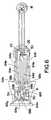
- Fig. 3 is a plan view of the bottom of an oximetry measuring means according to anembodiment of the present invention;
- Fig. 4 is a plan view of a leadframe assembly in the oximetry measuring means;
- Fig. 5 is an expanded view of a portion of the leadframe assembly containing the LEDs;
- Fig. 6 is a view of a connector on the sensor leadframe assembly;
- Figs. 7A and 7B are side and front views of the connector attached to the leadframeassembly; and
- Fig. 8 is one embodiment of the sensor circuitry.
- As shown in Figs. 2-8, the sensor assemblies 2a,b each includes a measuring means10a,b and an interconnect cable 4a,b. The measuring means 10a,b each includes (i) a
sensor housing 14 containing (a) adetector 18, (b) each first, second andthird emitters leadframe 60; (ii)connector 6a,b; and (iii) an interconnect cable 4a,b. Theconnector 6a,b connects to a sensorplug 8a,b on one end of the interconnect cable 4a,b, and an oximeter plug 12a,b on theother end of the interconnect cable 4a,b connects to the corresponding oximeterprocessing and display unit 16a,b. Thearm 21 of the measuring means is bent about the axis A-A to conform to the shape of a body part, such as the tip of a finger, to placethedetector 18 in an opposing relationship to theemitters areas detector 18.Thedetector 18 generates an output signal in response to the unabsorbed radiationreceived by the detector, with the output signals being employable to determine theoxygen saturation of the blood. - The
sensor housing transparent windows 42a,b locatedover the detector and radiation emitting devices to pass radiation. - The
detector 18 is preferably a photodiode or other suitable device for producing anelectrical signal in response to the incidence of radiation on the detector surface. Aswill be appreciated, the current output of a photodiode is directly related to the amountof radiation contacting the detector surface. Thus, in a typical application, thephotodiode will produce a time-varying signal in response to the contact of time-varyingamounts of radiation upon the detector surface. - The emitters are preferably LEDs which are broad band radiation sources providingsubstantially different spectral contents (i.e., the spectral contents are characterized bydifferent central wavelengths). The
first emitter 26 typically provides infrared radiationwhile the second andthird emitters - The spectral contents provided by the
emitters sensor assembly 10 to be used withoximeter processing and display units manufactured by the different oximetermanufacturers. In a first mode at least two of the first, second andthird emitters thirdemitters - A common infrared emitter is typically used with different sets of red emitters to providethe desired spectral content sets. As will be appreciated, it is nonetheless possible touse a common red emitter with two different infrared emitters.
- The red and infrared emitters can have single or multiple peak wavelengths dependingupon the application. By way of example, one of the red emitters can have a singlepeak radiation wavelength and the other red emitter can have multiple peak radiationwavelengths.
- The process to select the desired radiation wavelength distributions for the radiationemitting devices to provide a sensor that can be used with a variety of oximeterprocessing and display units requires the identification of the spectral content set thatcorresponds to one or more of the correlation curves used by each oximeter processingand display unit. In one approach, the red and infrared emitters used in theconventional sensor manufactured specifically for an oximeter processing and displayunit can be combined with the red and infrared emitters specifically manufactured foranother manufacturer's oximeter processing and display unit. Thus, in this example themeasuring means of the present invention would have two infrared emitters and two red emitters. As will be appreciated, the number of pairs of red and infrared emitters in themeasuring means using this approach depends upon the number of oximeterprocessing and display units with which compatibility is desired. In another approach,two or more suitable red emitters and a common infrared emitter are selected such thatthe emitters produce a number of possible spectral content sets. The application of theoximeter processing and display unit's correlation curve to one of the resulting spectralcontent sets produces a blood oxygen saturation within an acceptable degree ofaccuracy of the actual oxygen saturation for the blood. The desired degree of accuracyis generally that specified by the particular manufacturer. Thus, the red and infraredemitters are selected such that the spectral content set when applied to the particularcorrelation curve for the oximeter processing and display unit produces a measurementfor the blood oxygen saturation having a saturation error less than or equal to thatspecified by the manufacturer for the specific oximeter processing and display unit.
- To permit each oximeter processing and display unit to determine the appropriatecorrelation curve to employ for the
sensor assembly 10, thesensor assembly 10includes identification means 50 and 54, each typically providing a different signal to theappropriate unit. By way of example, the identification means can be resistors witheach resistor having a resistance that the corresponding oximeter processing anddisplay unit would recognize as correlating to a specific correlation curve. Theidentification means are electrically energized one at a time (e.g., by being connectedto different pins on the connector) such that, when the first identification means isbiased by the first oximeter processing and display unit, the second identificationmeans is not biased by the first oximeter processing and display unit, and, when thesecond identification means is biased by the second oximeter processing and displayunit, the first identification means is not biased by the second oximeter processing anddisplay unit. In this manner, the first oximeter processing and display unit sees only thefirst identification means, and the second oximeter processing and display unit seesonly the second identification means. - As will be appreciated, the identification means can be not only resistors but also a hostof other devices. By way of example, devices that vary an electrical parameter, namelycurrent, voltage or resistance, in other manners can be employed. U.S. Patent No.4,700,708 to New, Jr., et al., which is incorporated herein by this reference, disclosesthat the identification means devices can include devices besides resistors, namely aconnector wired to provide a digital value or binary array or a disposable memorycontaining the identification information.
- Referring to Figs. 2-5, the sensor housing includes a
flexible leadframe 60 forselectively connecting the detector, radiation emitting devices, and identification meansto the oximeter processing and display unit via the sensor and interconnect cables.The leadframe includes a plurality ofleads 64a-h having a plurality ofcorrespondingconnection points 68a-h.Leads 64a,b andconnection points 68a,b appropriately biasthedetector 18.Leads 64c,d andconnection points 68c,d appropriately bias theemitter 22.Leads 64e,f andconnection points 68e,f appropriately bias theemitter Leads 64c,g and 64h,g andconnection points 68c,g and 68h,g appropriatelyconnect the identification means 54 and 50, respectively. - Figs. 6, 7A and 7B illustrate the connection of the
connector 6 to theemitters emitters pins 72e,f which are connected to theconnectionpoints 68e,f. As shown in Fig. 8, the polarities of theemitters emitter 22 is activated by appropriately biasing thepins 72c,dwhich are connected to the connection points 68c,d. Thedetector 18 is activated byappropriately biasing thepins 72a,b which are connected to theconnection points 68a,b. Finally, the identification means 50 and 54 are activated by biasing thepins 72h,g and 72c,g, respectively, which are connected to the connection points 68h,g and68c,g, respectively. - Referring again to Fig. 2, the interconnect cable 4 a,b provides for adaptability of themeasuring means 10a,b with the first and second oximeter processing and displayunits 16a,b. The
connectors 6a,b can be connected to either plug 8a or b. As shown inFig. 2, however, the oximeter plugs 12a,b have the same or a different number of pins,differing pin configurations and/or housing shapes which are specific to the particularoximeter manufacturer. By way of example, the appropriate emitters are energized bythe pin configuration of 8a and 8b. Each interconnection cable will thus incorporate thepin configuration on the other end of the interconnect cable to achieve compatibilitybetween thesensor assembly 10 and the particular oximeter processing and displayunit. Each interconnect cable can incorporate labeling which clearly indicatesspecifically which oximeter processing and display units the cable is compatible with. Acolor coding scheme, for example, is one method that can be used to indicatecompatibility. - The operation of the
sensor assembly 10 and attached oximeter processing and displayunit will now be described with reference to Fig. 2. Theconnector 6 of the measuringmeans 10 is attached to thesensor plug 8 on theinterconnect cable 4 and the oximeterplug 12 on the other end of interconnect cable is attached to the plug (not shown) onthe oximeter processing and display unit 16. - The measuring means is positioned on the body part of the patient as described above.The oximeter appropriately energizes the pins of the oximeter plug 12 which thenenergizes the appropriate emitters via
connector 8. The pin configuration dependsupon the specific oximeter processing and display unit employed. In response to theapplied voltage, theemitter 26 and either one of theemitters emitters 26 and eitheremitter 22 and/or 30 are activated at different times). The spectral components of each emittersequentially pass through the tissue forming an absorbed portion and an unabsorbedportion of each spectral component. The unabsorbed portions of the spectralcomponents are sequentially received by thedetector 18 with separate measurements being taken for each portion. In response to the time-varying intensities of each of theunabsorbed radiation portions, thedetector 18 produces a time-varying signalcorresponding to each portion. Another measurement is taken with all of the emittersbeing "off" to quantify the noise from ambient radiation. Based on the identificationmeans in the measuring means 10 biased by the particular oximeter processing anddisplay unit, the oximeter processing and display unit selects an appropriate correlationcurve and, based on the correlation curve, analyzes the time varying signals from thevarious measurements to estimate the oxygen saturation in the patient's bloodstream. - As will be appreciated, there are a variety of other embodiments of the presentinvention depending upon the application. In other embodiments, the sensor assemblycan include more than one infrared and/or more than two red radiation emitting devicesand, therefore, more than two resistors. One resistor is typically required for each ofthe possible combinations of infrared and red radiation emitting devices.
Claims (11)
- A sensor for an oximeter processing and display unit comprising:characterised in that 1)the emitter means (22,26,30) comprising aplurality of at least three emitters respectively providing a plurality of spectralcontents, 2) the connecting means (4a,4b) is capable of connecting themeasuring means with one of a first and second oximeter processing anddisplay unit (16a,16b), and 3) the emitter means (22,26,30) is capable ofoperating:(a) measuring means (10) for providing a signal related to oxygen level in apatient's blood, the signal being a function of an unabsorbed portion ofradiation passed by the blood, the measuring means including:(i) emitter means (22,26,30) for irradiating said blood,; and(ii) detecting means (18) for receiving radiation passed by the blood;and(b) connecting means (4a,4b) for connecting the measuring means with anoximeter processing and display unit,the first and second sets of emitters being different.(i) in a first mode when the connecting means (4a,4b) is attached to thefirst oximeter processing and display unit, wherein, in the firstmode, a first set of at least two of the plurality of emitters isactivated to generate a first spectral content set and(ii) in a second mode when the connecting means (4a,4b) is attached tothe second oximeter processing and display unit, wherein, in thesecond mode, a second set of at least two of the plurality of emitters isactivated to generate a second cumulative spectral content set,
- The sensor of Claim 1, wherein the first and second spectral content setshave different central wavelengths.
- The sensor of Claim 1, further comprising a first identification means (50) foridentifying to a first oximeter processing and display unit (16a) to use a firstcorrelation curve and a second identification means (54) for identifying to asecond oximeter processing and display unit (16a) to use a second correlationcurve, the first and second identification means being different.
- The sensor of Claim 2, wherein the sensor allows that only one of the first andsecond sets of emitters is activated during a selected time interval.
- The sensor of Claim 1, wherein the connecting means (4a,4b) comprises:a first interconnect cable having a first oximeter plug (12a) forconnecting to a first oximeter processing and display unit; anda second interconnect cable having a second oximeter plug (12b) forconnecting to a second oximeter processing and display unit, the firstand second oximeter plugs having different pin configurations.
- The sensor of Claim 5, wherein the first interconnect cable (4a) has a firstsensor plug (8a) and the second interconnect cable (4b) has a second sensorplug (8b) for connecting to a connector (6a,6b) on said measuring means, thefirst and second sensor plugs (8a,8b) being interchangeably connectable withsaid connector (6a,6b).
- The sensor of any preceding claim wherein the emitters (22,26,30)comprise broadband radiation sources operative to provide multiple peakwavelengths.
- Apparatus comprising a sensor (10) as claimed in any one of claims 1 to7 and an oximeter processing and display unit (16a).
- The apparatus of Claim 8, which includes a second oximeter processingand display unit (16a) and wherein the sensor is adaptable to the first andsecond oximeter processing and display units, the connecting means (4a,4b) iscapable of connecting the measuring means with either one of the first andsecond oximeter processing and display units (16a,16b) and 4) and the emittermeans (22,26,30) is capable of operating:the first and second sets of emitters being different.(ii) in a first mode when the connecting means (4a,4b) is attached to thefirst oximeter processing and display unit, wherein, in the firstmode, a first set of at least two of the plurality of emitters isactivated to generate a first spectral content set and(ii) in a second mode when the connecting means (4a,4b) is attached tothe second oximeter processing and display unit, wherein, in thesecond mode, a second set of at least two of the plurality of emittersare activated to generate a second cumulative spectral content set,
- The apparatus of Claim 9, wherein the sensor (10) further comprises a firstidentification means (50) and a second identification means (54) and whereinthe first and second oximeter processing and display units (16a, 16b) includemeans for identifying the first and second identification means (50,54) andmeans to determine a correlation curve for use with the sensor in accordancewith identification means.
- The apparatus of Claim 9, wherein the first and second spectral content setsdiffer from one another and wherein, in said first mode when said emittermeans (22,26,30) is connected to the first oximeter processing and display unit (16a), said first spectral content set corresponds to a first correlation curve forsaid first oximeter processing and display unit (16a) and, in said second modewhen said emitter means (22,26,30) is connected to a second oximeterprocessing and display unit (16b), said second spectral content set correspondsto a second correlation curve for said second oximeter processing and displayunit.
Applications Claiming Priority (2)
| Application Number | Priority Date | Filing Date | Title |
|---|---|---|---|
| US08/829,258US5827182A (en) | 1997-03-31 | 1997-03-31 | Multiple LED sets in oximetry sensors |
| US829258 | 1997-03-31 |
Publications (3)
| Publication Number | Publication Date |
|---|---|
| EP0868879A2 EP0868879A2 (en) | 1998-10-07 |
| EP0868879A3 EP0868879A3 (en) | 1999-05-26 |
| EP0868879B1true EP0868879B1 (en) | 2004-08-11 |
Family
ID=25253993
Family Applications (1)
| Application Number | Title | Priority Date | Filing Date |
|---|---|---|---|
| EP98302025AExpired - LifetimeEP0868879B1 (en) | 1997-03-31 | 1998-03-18 | Multiple led sets in oximeter sensors |
Country Status (5)
| Country | Link |
|---|---|
| US (1) | US5827182A (en) |
| EP (1) | EP0868879B1 (en) |
| JP (1) | JPH10305026A (en) |
| DE (1) | DE69825518D1 (en) |
| ES (1) | ES2224334T3 (en) |
Families Citing this family (98)
| Publication number | Priority date | Publication date | Assignee | Title |
|---|---|---|---|---|
| US6675031B1 (en) | 1999-04-14 | 2004-01-06 | Mallinckrodt Inc. | Method and circuit for indicating quality and accuracy of physiological measurements |
| EP1274343B1 (en) | 2000-04-17 | 2012-08-15 | Nellcor Puritan Bennett LLC | Pulse oximeter sensor with piece-wise function |
| US8224412B2 (en) | 2000-04-17 | 2012-07-17 | Nellcor Puritan Bennett Llc | Pulse oximeter sensor with piece-wise function |
| US6889153B2 (en)* | 2001-08-09 | 2005-05-03 | Thomas Dietiker | System and method for a self-calibrating non-invasive sensor |
| AT5042U3 (en)* | 2001-10-08 | 2002-10-25 | Avl List Gmbh | MEASURING DEVICE |
| US6748254B2 (en) | 2001-10-12 | 2004-06-08 | Nellcor Puritan Bennett Incorporated | Stacked adhesive optical sensor |
| US7190986B1 (en) | 2002-10-18 | 2007-03-13 | Nellcor Puritan Bennett Inc. | Non-adhesive oximeter sensor for sensitive skin |
| US7027849B2 (en)* | 2002-11-22 | 2006-04-11 | Masimo Laboratories, Inc. | Blood parameter measurement system |
| US7162288B2 (en) | 2004-02-25 | 2007-01-09 | Nellcor Purtain Bennett Incorporated | Techniques for detecting heart pulses and reducing power consumption in sensors |
| US7343186B2 (en)* | 2004-07-07 | 2008-03-11 | Masimo Laboratories, Inc. | Multi-wavelength physiological monitor |
| US20070048096A1 (en)* | 2004-12-07 | 2007-03-01 | Hubbs Jonathan W | Soil conditioner |
| US7706853B2 (en)* | 2005-02-10 | 2010-04-27 | Terumo Cardiovascular Systems Corporation | Near infrared spectroscopy device with reusable portion |
| US7647083B2 (en) | 2005-03-01 | 2010-01-12 | Masimo Laboratories, Inc. | Multiple wavelength sensor equalization |
| US7590439B2 (en) | 2005-08-08 | 2009-09-15 | Nellcor Puritan Bennett Llc | Bi-stable medical sensor and technique for using the same |
| US7657294B2 (en) | 2005-08-08 | 2010-02-02 | Nellcor Puritan Bennett Llc | Compliant diaphragm medical sensor and technique for using the same |
| US7657295B2 (en) | 2005-08-08 | 2010-02-02 | Nellcor Puritan Bennett Llc | Medical sensor and technique for using the same |
| US20070060808A1 (en) | 2005-09-12 | 2007-03-15 | Carine Hoarau | Medical sensor for reducing motion artifacts and technique for using the same |
| US8092379B2 (en) | 2005-09-29 | 2012-01-10 | Nellcor Puritan Bennett Llc | Method and system for determining when to reposition a physiological sensor |
| US7899510B2 (en) | 2005-09-29 | 2011-03-01 | Nellcor Puritan Bennett Llc | Medical sensor and technique for using the same |
| US7904130B2 (en) | 2005-09-29 | 2011-03-08 | Nellcor Puritan Bennett Llc | Medical sensor and technique for using the same |
| US7869850B2 (en) | 2005-09-29 | 2011-01-11 | Nellcor Puritan Bennett Llc | Medical sensor for reducing motion artifacts and technique for using the same |
| US7555327B2 (en) | 2005-09-30 | 2009-06-30 | Nellcor Puritan Bennett Llc | Folding medical sensor and technique for using the same |
| US8062221B2 (en) | 2005-09-30 | 2011-11-22 | Nellcor Puritan Bennett Llc | Sensor for tissue gas detection and technique for using the same |
| US7483731B2 (en) | 2005-09-30 | 2009-01-27 | Nellcor Puritan Bennett Llc | Medical sensor and technique for using the same |
| US7881762B2 (en) | 2005-09-30 | 2011-02-01 | Nellcor Puritan Bennett Llc | Clip-style medical sensor and technique for using the same |
| US8233954B2 (en) | 2005-09-30 | 2012-07-31 | Nellcor Puritan Bennett Llc | Mucosal sensor for the assessment of tissue and blood constituents and technique for using the same |
| US7486979B2 (en) | 2005-09-30 | 2009-02-03 | Nellcor Puritan Bennett Llc | Optically aligned pulse oximetry sensor and technique for using the same |
| EP1792564B1 (en) | 2005-12-02 | 2010-11-24 | General Electric Company | A probe and a method for use with a probe |
| US8073518B2 (en) | 2006-05-02 | 2011-12-06 | Nellcor Puritan Bennett Llc | Clip-style medical sensor and technique for using the same |
| US7477924B2 (en) | 2006-05-02 | 2009-01-13 | Nellcor Puritan Bennett Llc | Medical sensor and technique for using the same |
| US7522948B2 (en) | 2006-05-02 | 2009-04-21 | Nellcor Puritan Bennett Llc | Medical sensor and technique for using the same |
| WO2008002405A2 (en)* | 2006-06-16 | 2008-01-03 | Medtor Llc | System and method for a non-invasive medical sensor |
| US8145288B2 (en) | 2006-08-22 | 2012-03-27 | Nellcor Puritan Bennett Llc | Medical sensor for reducing signal artifacts and technique for using the same |
| US8219170B2 (en) | 2006-09-20 | 2012-07-10 | Nellcor Puritan Bennett Llc | System and method for practicing spectrophotometry using light emitting nanostructure devices |
| US8175671B2 (en) | 2006-09-22 | 2012-05-08 | Nellcor Puritan Bennett Llc | Medical sensor for reducing signal artifacts and technique for using the same |
| US8195264B2 (en) | 2006-09-22 | 2012-06-05 | Nellcor Puritan Bennett Llc | Medical sensor for reducing signal artifacts and technique for using the same |
| US8396527B2 (en) | 2006-09-22 | 2013-03-12 | Covidien Lp | Medical sensor for reducing signal artifacts and technique for using the same |
| US7869849B2 (en) | 2006-09-26 | 2011-01-11 | Nellcor Puritan Bennett Llc | Opaque, electrically nonconductive region on a medical sensor |
| US7574245B2 (en) | 2006-09-27 | 2009-08-11 | Nellcor Puritan Bennett Llc | Flexible medical sensor enclosure |
| US7890153B2 (en) | 2006-09-28 | 2011-02-15 | Nellcor Puritan Bennett Llc | System and method for mitigating interference in pulse oximetry |
| US7796403B2 (en) | 2006-09-28 | 2010-09-14 | Nellcor Puritan Bennett Llc | Means for mechanical registration and mechanical-electrical coupling of a faraday shield to a photodetector and an electrical circuit |
| US7684842B2 (en) | 2006-09-29 | 2010-03-23 | Nellcor Puritan Bennett Llc | System and method for preventing sensor misuse |
| US7476131B2 (en) | 2006-09-29 | 2009-01-13 | Nellcor Puritan Bennett Llc | Device for reducing crosstalk |
| US8175667B2 (en) | 2006-09-29 | 2012-05-08 | Nellcor Puritan Bennett Llc | Symmetric LED array for pulse oximetry |
| US8068891B2 (en) | 2006-09-29 | 2011-11-29 | Nellcor Puritan Bennett Llc | Symmetric LED array for pulse oximetry |
| US7680522B2 (en) | 2006-09-29 | 2010-03-16 | Nellcor Puritan Bennett Llc | Method and apparatus for detecting misapplied sensors |
| US8265723B1 (en) | 2006-10-12 | 2012-09-11 | Cercacor Laboratories, Inc. | Oximeter probe off indicator defining probe off space |
| US8280469B2 (en) | 2007-03-09 | 2012-10-02 | Nellcor Puritan Bennett Llc | Method for detection of aberrant tissue spectra |
| US8265724B2 (en) | 2007-03-09 | 2012-09-11 | Nellcor Puritan Bennett Llc | Cancellation of light shunting |
| US7894869B2 (en) | 2007-03-09 | 2011-02-22 | Nellcor Puritan Bennett Llc | Multiple configuration medical sensor and technique for using the same |
| EP2139383B1 (en) | 2007-03-27 | 2013-02-13 | Masimo Laboratories, Inc. | Multiple wavelength optical sensor |
| US8374665B2 (en) | 2007-04-21 | 2013-02-12 | Cercacor Laboratories, Inc. | Tissue profile wellness monitor |
| US8346328B2 (en) | 2007-12-21 | 2013-01-01 | Covidien Lp | Medical sensor and technique for using the same |
| US8352004B2 (en) | 2007-12-21 | 2013-01-08 | Covidien Lp | Medical sensor and technique for using the same |
| US8366613B2 (en) | 2007-12-26 | 2013-02-05 | Covidien Lp | LED drive circuit for pulse oximetry and method for using same |
| US8577434B2 (en) | 2007-12-27 | 2013-11-05 | Covidien Lp | Coaxial LED light sources |
| US8452364B2 (en) | 2007-12-28 | 2013-05-28 | Covidien LLP | System and method for attaching a sensor to a patient's skin |
| US8442608B2 (en) | 2007-12-28 | 2013-05-14 | Covidien Lp | System and method for estimating physiological parameters by deconvolving artifacts |
| US8092993B2 (en) | 2007-12-31 | 2012-01-10 | Nellcor Puritan Bennett Llc | Hydrogel thin film for use as a biosensor |
| US8070508B2 (en) | 2007-12-31 | 2011-12-06 | Nellcor Puritan Bennett Llc | Method and apparatus for aligning and securing a cable strain relief |
| US8897850B2 (en) | 2007-12-31 | 2014-11-25 | Covidien Lp | Sensor with integrated living hinge and spring |
| US8199007B2 (en) | 2007-12-31 | 2012-06-12 | Nellcor Puritan Bennett Llc | Flex circuit snap track for a biometric sensor |
| US8437822B2 (en) | 2008-03-28 | 2013-05-07 | Covidien Lp | System and method for estimating blood analyte concentration |
| US8364224B2 (en) | 2008-03-31 | 2013-01-29 | Covidien Lp | System and method for facilitating sensor and monitor communication |
| US8112375B2 (en) | 2008-03-31 | 2012-02-07 | Nellcor Puritan Bennett Llc | Wavelength selection and outlier detection in reduced rank linear models |
| US8071935B2 (en) | 2008-06-30 | 2011-12-06 | Nellcor Puritan Bennett Llc | Optical detector with an overmolded faraday shield |
| US7887345B2 (en) | 2008-06-30 | 2011-02-15 | Nellcor Puritan Bennett Llc | Single use connector for pulse oximetry sensors |
| US7880884B2 (en) | 2008-06-30 | 2011-02-01 | Nellcor Puritan Bennett Llc | System and method for coating and shielding electronic sensor components |
| US20100004518A1 (en) | 2008-07-03 | 2010-01-07 | Masimo Laboratories, Inc. | Heat sink for noninvasive medical sensor |
| US8515509B2 (en) | 2008-08-04 | 2013-08-20 | Cercacor Laboratories, Inc. | Multi-stream emitter for noninvasive measurement of blood constituents |
| US8364220B2 (en) | 2008-09-25 | 2013-01-29 | Covidien Lp | Medical sensor and technique for using the same |
| US8423112B2 (en) | 2008-09-30 | 2013-04-16 | Covidien Lp | Medical sensor and technique for using the same |
| US8417309B2 (en) | 2008-09-30 | 2013-04-09 | Covidien Lp | Medical sensor |
| US8914088B2 (en) | 2008-09-30 | 2014-12-16 | Covidien Lp | Medical sensor and technique for using the same |
| US20100088957A1 (en)* | 2008-10-09 | 2010-04-15 | Hubbs Jonathan W | Natural turf with binder |
| KR101047547B1 (en)* | 2008-10-30 | 2011-07-07 | 주식회사 메디칼써프라이 | Method for Increasing Compatibility of Oxygen Saturation Measuring Sensor Using Light Output Characteristics |
| US20100216639A1 (en)* | 2009-02-20 | 2010-08-26 | Hubbs Jonathon W | Gypsum soil conditioner |
| US8216136B2 (en) | 2009-03-05 | 2012-07-10 | Nellcor Puritan Bennett Llc | Systems and methods for monitoring heart rate and blood pressure correlation |
| US8452366B2 (en) | 2009-03-16 | 2013-05-28 | Covidien Lp | Medical monitoring device with flexible circuitry |
| US8221319B2 (en) | 2009-03-25 | 2012-07-17 | Nellcor Puritan Bennett Llc | Medical device for assessing intravascular blood volume and technique for using the same |
| US8509869B2 (en) | 2009-05-15 | 2013-08-13 | Covidien Lp | Method and apparatus for detecting and analyzing variations in a physiologic parameter |
| US8634891B2 (en) | 2009-05-20 | 2014-01-21 | Covidien Lp | Method and system for self regulation of sensor component contact pressure |
| US9010634B2 (en) | 2009-06-30 | 2015-04-21 | Covidien Lp | System and method for linking patient data to a patient and providing sensor quality assurance |
| US8311601B2 (en) | 2009-06-30 | 2012-11-13 | Nellcor Puritan Bennett Llc | Reflectance and/or transmissive pulse oximeter |
| US8505821B2 (en) | 2009-06-30 | 2013-08-13 | Covidien Lp | System and method for providing sensor quality assurance |
| US8391941B2 (en) | 2009-07-17 | 2013-03-05 | Covidien Lp | System and method for memory switching for multiple configuration medical sensor |
| US8417310B2 (en) | 2009-08-10 | 2013-04-09 | Covidien Lp | Digital switching in multi-site sensor |
| US8428675B2 (en) | 2009-08-19 | 2013-04-23 | Covidien Lp | Nanofiber adhesives used in medical devices |
| US9066660B2 (en) | 2009-09-29 | 2015-06-30 | Nellcor Puritan Bennett Ireland | Systems and methods for high-pass filtering a photoplethysmograph signal |
| US9839381B1 (en) | 2009-11-24 | 2017-12-12 | Cercacor Laboratories, Inc. | Physiological measurement system with automatic wavelength adjustment |
| WO2011069122A1 (en) | 2009-12-04 | 2011-06-09 | Masimo Corporation | Calibration for multi-stage physiological monitors |
| US8805465B2 (en) | 2010-11-30 | 2014-08-12 | Covidien Lp | Multiple sensor assemblies and cables in a single sensor body |
| DE202013011157U1 (en)* | 2013-12-17 | 2014-02-19 | Continental Teves Ag & Co. Ohg | Sensor with integrated identification device |
| US10485463B2 (en) | 2014-10-10 | 2019-11-26 | Medtor Llc | System and method for a non-invasive medical sensor |
| US9872621B2 (en)* | 2014-12-17 | 2018-01-23 | Intel Corporation | Multispectral measurement for improved biological signal acquisition |
| EP3315071A4 (en)* | 2015-07-30 | 2018-07-04 | Alps Electric Co., Ltd. | Sensor module and biometric information display system |
| TWI756218B (en)* | 2016-04-20 | 2022-03-01 | 美商菲歐普提斯公司 | Probe cover for an oximeter device, kit and method for forming a kit |
| US11998298B2 (en) | 2018-02-26 | 2024-06-04 | Biointellisense, Inc. | System and method for a wearable vital signs monitor |
Family Cites Families (16)
| Publication number | Priority date | Publication date | Assignee | Title |
|---|---|---|---|---|
| US3720201A (en)* | 1969-12-01 | 1973-03-13 | Ramtech | Disposable body fluid pressure monitor |
| US3890962A (en)* | 1970-10-28 | 1975-06-24 | Ramtech | Disposable manometer |
| US3785367A (en)* | 1972-03-13 | 1974-01-15 | Pharmasel Division American Ho | Arterial blood sampler |
| US3942514A (en)* | 1974-02-28 | 1976-03-09 | Ims Limited | Arterial blood sampling device with indicator |
| US3890842A (en)* | 1974-04-23 | 1975-06-24 | Ramtech | Disposable manometer |
| US4036216A (en)* | 1975-09-04 | 1977-07-19 | Ramsey Iii Maynard | Body fluid pressure system |
| US4135509A (en)* | 1977-04-26 | 1979-01-23 | Sherwood Medical Industries Inc. | Fluid pressure manometer |
| US4557269A (en)* | 1983-06-22 | 1985-12-10 | Abbott Laboratories | Disposable transducer apparatus for an electromanometry system |
| USRE33360E (en)* | 1983-06-22 | 1990-10-02 | Abbott Laboratories | Disposable transducer apparatus for an electromanometry system |
| JPH02291838A (en)* | 1989-05-02 | 1990-12-03 | Nec Corp | Disposable blood pressure transducer |
| US5058588A (en)* | 1989-09-19 | 1991-10-22 | Hewlett-Packard Company | Oximeter and medical sensor therefor |
| US5190038A (en)* | 1989-11-01 | 1993-03-02 | Novametrix Medical Systems, Inc. | Pulse oximeter with improved accuracy and response time |
| US5249576A (en)* | 1991-10-24 | 1993-10-05 | Boc Health Care, Inc. | Universal pulse oximeter probe |
| US5314410A (en)* | 1992-02-10 | 1994-05-24 | Marks Ronald L | Entry indicator device for arterial or intravenous needle |
| US5851178A (en)* | 1995-06-02 | 1998-12-22 | Ohmeda Inc. | Instrumented laser diode probe connector |
| US5758644A (en)* | 1995-06-07 | 1998-06-02 | Masimo Corporation | Manual and automatic probe calibration |
- 1997
- 1997-03-31USUS08/829,258patent/US5827182A/ennot_activeExpired - Lifetime
- 1998
- 1998-03-18DEDE69825518Tpatent/DE69825518D1/ennot_activeExpired - Lifetime
- 1998-03-18ESES98302025Tpatent/ES2224334T3/ennot_activeExpired - Lifetime
- 1998-03-18EPEP98302025Apatent/EP0868879B1/ennot_activeExpired - Lifetime
- 1998-03-30JPJP10083871Apatent/JPH10305026A/enactivePending
Also Published As
| Publication number | Publication date |
|---|---|
| JPH10305026A (en) | 1998-11-17 |
| DE69825518D1 (en) | 2004-09-16 |
| EP0868879A3 (en) | 1999-05-26 |
| US5827182A (en) | 1998-10-27 |
| EP0868879A2 (en) | 1998-10-07 |
| ES2224334T3 (en) | 2005-03-01 |
Similar Documents
| Publication | Publication Date | Title |
|---|---|---|
| EP0868879B1 (en) | Multiple led sets in oximeter sensors | |
| RU2199723C2 (en) | Light source with adjustable wave length for oxyhemometer | |
| US5058588A (en) | Oximeter and medical sensor therefor | |
| US6014576A (en) | Segmented photoplethysmographic sensor with universal probe-end | |
| US5259382A (en) | Optical transcutaneous bilirubin detector | |
| US5660567A (en) | Medical sensor connector with removable encoding device | |
| US6044283A (en) | Medical sensor with modulated encoding scheme | |
| EP0104772B1 (en) | Calibrated optical oximeter probe | |
| EP0435500A1 (en) | Non-invasive sensor | |
| EP0871396A1 (en) | Method and apparatus for facilitating compatibility between pulse oximeters and sensor probes | |
| EP0329196B1 (en) | Oximeter for cooperation with an oximeter probe | |
| AU729132B2 (en) | Manual and automatic probe calibration | |
| Kronberg | Optical transcutaneous bilirubin detector | |
| HK1009848B (en) | Oximeter comprising a light source and an information element |
Legal Events
| Date | Code | Title | Description |
|---|---|---|---|
| PUAI | Public reference made under article 153(3) epc to a published international application that has entered the european phase | Free format text:ORIGINAL CODE: 0009012 | |
| AK | Designated contracting states | Kind code of ref document:A2 Designated state(s):DE ES FR GB | |
| PUAL | Search report despatched | Free format text:ORIGINAL CODE: 0009013 | |
| AK | Designated contracting states | Kind code of ref document:A3 Designated state(s):AT BE CH DE DK ES FI FR GB GR IE IT LI LU MC NL PT SE | |
| AX | Request for extension of the european patent | Free format text:AL;LT;LV;MK;RO;SI | |
| RAP1 | Party data changed (applicant data changed or rights of an application transferred) | Owner name:DATEX-OHMEDA, INC. | |
| 17P | Request for examination filed | Effective date:19991126 | |
| AKX | Designation fees paid | Free format text:DE ES FR GB | |
| 17Q | First examination report despatched | Effective date:20030429 | |
| GRAP | Despatch of communication of intention to grant a patent | Free format text:ORIGINAL CODE: EPIDOSNIGR1 | |
| GRAS | Grant fee paid | Free format text:ORIGINAL CODE: EPIDOSNIGR3 | |
| GRAA | (expected) grant | Free format text:ORIGINAL CODE: 0009210 | |
| AK | Designated contracting states | Kind code of ref document:B1 Designated state(s):DE ES FR GB | |
| PG25 | Lapsed in a contracting state [announced via postgrant information from national office to epo] | Ref country code:FR Free format text:LAPSE BECAUSE OF FAILURE TO SUBMIT A TRANSLATION OF THE DESCRIPTION OR TO PAY THE FEE WITHIN THE PRESCRIBED TIME-LIMIT Effective date:20040811 | |
| REG | Reference to a national code | Ref country code:GB Ref legal event code:FG4D | |
| REF | Corresponds to: | Ref document number:69825518 Country of ref document:DE Date of ref document:20040916 Kind code of ref document:P | |
| PG25 | Lapsed in a contracting state [announced via postgrant information from national office to epo] | Ref country code:DE Free format text:LAPSE BECAUSE OF FAILURE TO SUBMIT A TRANSLATION OF THE DESCRIPTION OR TO PAY THE FEE WITHIN THE PRESCRIBED TIME-LIMIT Effective date:20041112 | |
| REG | Reference to a national code | Ref country code:ES Ref legal event code:FG2A Ref document number:2224334 Country of ref document:ES Kind code of ref document:T3 | |
| PLBE | No opposition filed within time limit | Free format text:ORIGINAL CODE: 0009261 | |
| STAA | Information on the status of an ep patent application or granted ep patent | Free format text:STATUS: NO OPPOSITION FILED WITHIN TIME LIMIT | |
| 26N | No opposition filed | Effective date:20050512 | |
| EN | Fr: translation not filed | ||
| EN | Fr: translation not filed | ||
| PGFP | Annual fee paid to national office [announced via postgrant information from national office to epo] | Ref country code:GB Payment date:20170327 Year of fee payment:20 | |
| PGFP | Annual fee paid to national office [announced via postgrant information from national office to epo] | Ref country code:ES Payment date:20170328 Year of fee payment:20 | |
| REG | Reference to a national code | Ref country code:GB Ref legal event code:PE20 Expiry date:20180317 | |
| PG25 | Lapsed in a contracting state [announced via postgrant information from national office to epo] | Ref country code:GB Free format text:LAPSE BECAUSE OF EXPIRATION OF PROTECTION Effective date:20180317 | |
| REG | Reference to a national code | Ref country code:ES Ref legal event code:FD2A Effective date:20200806 | |
| PG25 | Lapsed in a contracting state [announced via postgrant information from national office to epo] | Ref country code:ES Free format text:LAPSE BECAUSE OF EXPIRATION OF PROTECTION Effective date:20180319 |