EP0867798A2 - Data processing system user interface - Google Patents
Data processing system user interfaceDownload PDFInfo
- Publication number
- EP0867798A2 EP0867798A2EP98301693AEP98301693AEP0867798A2EP 0867798 A2EP0867798 A2EP 0867798A2EP 98301693 AEP98301693 AEP 98301693AEP 98301693 AEP98301693 AEP 98301693AEP 0867798 A2EP0867798 A2EP 0867798A2
- Authority
- EP
- European Patent Office
- Prior art keywords
- control signals
- data processing
- control
- display
- processing system
- Prior art date
- Legal status (The legal status is an assumption and is not a legal conclusion. Google has not performed a legal analysis and makes no representation as to the accuracy of the status listed.)
- Withdrawn
Links
Images


Classifications
- G—PHYSICS
- G06—COMPUTING OR CALCULATING; COUNTING
- G06F—ELECTRIC DIGITAL DATA PROCESSING
- G06F3/00—Input arrangements for transferring data to be processed into a form capable of being handled by the computer; Output arrangements for transferring data from processing unit to output unit, e.g. interface arrangements
- G06F3/01—Input arrangements or combined input and output arrangements for interaction between user and computer
- G06F3/03—Arrangements for converting the position or the displacement of a member into a coded form
- G06F3/033—Pointing devices displaced or positioned by the user, e.g. mice, trackballs, pens or joysticks; Accessories therefor
- G06F3/038—Control and interface arrangements therefor, e.g. drivers or device-embedded control circuitry
- A—HUMAN NECESSITIES
- A63—SPORTS; GAMES; AMUSEMENTS
- A63F—CARD, BOARD, OR ROULETTE GAMES; INDOOR GAMES USING SMALL MOVING PLAYING BODIES; VIDEO GAMES; GAMES NOT OTHERWISE PROVIDED FOR
- A63F13/00—Video games, i.e. games using an electronically generated display having two or more dimensions
- A63F13/20—Input arrangements for video game devices
- A63F13/23—Input arrangements for video game devices for interfacing with the game device, e.g. specific interfaces between game controller and console
- A63F13/235—Input arrangements for video game devices for interfacing with the game device, e.g. specific interfaces between game controller and console using a wireless connection, e.g. infrared or piconet
- A—HUMAN NECESSITIES
- A63—SPORTS; GAMES; AMUSEMENTS
- A63F—CARD, BOARD, OR ROULETTE GAMES; INDOOR GAMES USING SMALL MOVING PLAYING BODIES; VIDEO GAMES; GAMES NOT OTHERWISE PROVIDED FOR
- A63F13/00—Video games, i.e. games using an electronically generated display having two or more dimensions
- A63F13/40—Processing input control signals of video game devices, e.g. signals generated by the player or derived from the environment
- A63F13/42—Processing input control signals of video game devices, e.g. signals generated by the player or derived from the environment by mapping the input signals into game commands, e.g. mapping the displacement of a stylus on a touch screen to the steering angle of a virtual vehicle
- A63F13/424—Processing input control signals of video game devices, e.g. signals generated by the player or derived from the environment by mapping the input signals into game commands, e.g. mapping the displacement of a stylus on a touch screen to the steering angle of a virtual vehicle involving acoustic input signals, e.g. by using the results of pitch or rhythm extraction or voice recognition
- A—HUMAN NECESSITIES
- A63—SPORTS; GAMES; AMUSEMENTS
- A63F—CARD, BOARD, OR ROULETTE GAMES; INDOOR GAMES USING SMALL MOVING PLAYING BODIES; VIDEO GAMES; GAMES NOT OTHERWISE PROVIDED FOR
- A63F13/00—Video games, i.e. games using an electronically generated display having two or more dimensions
- A63F13/80—Special adaptations for executing a specific game genre or game mode
- A63F13/843—Special adaptations for executing a specific game genre or game mode involving concurrently two or more players on the same game device, e.g. requiring the use of a plurality of controllers or of a specific view of game data for each player
- G—PHYSICS
- G05—CONTROLLING; REGULATING
- G05G—CONTROL DEVICES OR SYSTEMS INSOFAR AS CHARACTERISED BY MECHANICAL FEATURES ONLY
- G05G9/00—Manually-actuated control mechanisms provided with one single controlling member co-operating with two or more controlled members, e.g. selectively, simultaneously
- G05G9/02—Manually-actuated control mechanisms provided with one single controlling member co-operating with two or more controlled members, e.g. selectively, simultaneously the controlling member being movable in different independent ways, movement in each individual way actuating one controlled member only
- G05G9/04—Manually-actuated control mechanisms provided with one single controlling member co-operating with two or more controlled members, e.g. selectively, simultaneously the controlling member being movable in different independent ways, movement in each individual way actuating one controlled member only in which movement in two or more ways can occur simultaneously
- G05G9/047—Manually-actuated control mechanisms provided with one single controlling member co-operating with two or more controlled members, e.g. selectively, simultaneously the controlling member being movable in different independent ways, movement in each individual way actuating one controlled member only in which movement in two or more ways can occur simultaneously the controlling member being movable by hand about orthogonal axes, e.g. joysticks
- H—ELECTRICITY
- H04—ELECTRIC COMMUNICATION TECHNIQUE
- H04N—PICTORIAL COMMUNICATION, e.g. TELEVISION
- H04N21/00—Selective content distribution, e.g. interactive television or video on demand [VOD]
- H04N21/40—Client devices specifically adapted for the reception of or interaction with content, e.g. set-top-box [STB]; Operations thereof
- H04N21/41—Structure of client; Structure of client peripherals
- H04N21/422—Input-only peripherals, i.e. input devices connected to specially adapted client devices, e.g. global positioning system [GPS]
- H04N21/42204—User interfaces specially adapted for controlling a client device through a remote control device; Remote control devices therefor
- H—ELECTRICITY
- H04—ELECTRIC COMMUNICATION TECHNIQUE
- H04N—PICTORIAL COMMUNICATION, e.g. TELEVISION
- H04N21/00—Selective content distribution, e.g. interactive television or video on demand [VOD]
- H04N21/40—Client devices specifically adapted for the reception of or interaction with content, e.g. set-top-box [STB]; Operations thereof
- H04N21/47—End-user applications
- A—HUMAN NECESSITIES
- A63—SPORTS; GAMES; AMUSEMENTS
- A63F—CARD, BOARD, OR ROULETTE GAMES; INDOOR GAMES USING SMALL MOVING PLAYING BODIES; VIDEO GAMES; GAMES NOT OTHERWISE PROVIDED FOR
- A63F13/00—Video games, i.e. games using an electronically generated display having two or more dimensions
- A63F13/30—Interconnection arrangements between game servers and game devices; Interconnection arrangements between game devices; Interconnection arrangements between game servers
- A63F13/33—Interconnection arrangements between game servers and game devices; Interconnection arrangements between game devices; Interconnection arrangements between game servers using wide area network [WAN] connections
- A63F13/335—Interconnection arrangements between game servers and game devices; Interconnection arrangements between game devices; Interconnection arrangements between game servers using wide area network [WAN] connections using Internet
- A—HUMAN NECESSITIES
- A63—SPORTS; GAMES; AMUSEMENTS
- A63F—CARD, BOARD, OR ROULETTE GAMES; INDOOR GAMES USING SMALL MOVING PLAYING BODIES; VIDEO GAMES; GAMES NOT OTHERWISE PROVIDED FOR
- A63F2300/00—Features of games using an electronically generated display having two or more dimensions, e.g. on a television screen, showing representations related to the game
- A63F2300/10—Features of games using an electronically generated display having two or more dimensions, e.g. on a television screen, showing representations related to the game characterized by input arrangements for converting player-generated signals into game device control signals
- A63F2300/1025—Features of games using an electronically generated display having two or more dimensions, e.g. on a television screen, showing representations related to the game characterized by input arrangements for converting player-generated signals into game device control signals details of the interface with the game device, e.g. USB version detection
- A63F2300/1031—Features of games using an electronically generated display having two or more dimensions, e.g. on a television screen, showing representations related to the game characterized by input arrangements for converting player-generated signals into game device control signals details of the interface with the game device, e.g. USB version detection using a wireless connection, e.g. Bluetooth, infrared connections
- A—HUMAN NECESSITIES
- A63—SPORTS; GAMES; AMUSEMENTS
- A63F—CARD, BOARD, OR ROULETTE GAMES; INDOOR GAMES USING SMALL MOVING PLAYING BODIES; VIDEO GAMES; GAMES NOT OTHERWISE PROVIDED FOR
- A63F2300/00—Features of games using an electronically generated display having two or more dimensions, e.g. on a television screen, showing representations related to the game
- A63F2300/40—Features of games using an electronically generated display having two or more dimensions, e.g. on a television screen, showing representations related to the game characterised by details of platform network
- A63F2300/407—Data transfer via internet
- A—HUMAN NECESSITIES
- A63—SPORTS; GAMES; AMUSEMENTS
- A63F—CARD, BOARD, OR ROULETTE GAMES; INDOOR GAMES USING SMALL MOVING PLAYING BODIES; VIDEO GAMES; GAMES NOT OTHERWISE PROVIDED FOR
- A63F2300/00—Features of games using an electronically generated display having two or more dimensions, e.g. on a television screen, showing representations related to the game
- A63F2300/60—Methods for processing data by generating or executing the game program
- A63F2300/6063—Methods for processing data by generating or executing the game program for sound processing
- A63F2300/6072—Methods for processing data by generating or executing the game program for sound processing of an input signal, e.g. pitch and rhythm extraction, voice recognition
- A—HUMAN NECESSITIES
- A63—SPORTS; GAMES; AMUSEMENTS
- A63F—CARD, BOARD, OR ROULETTE GAMES; INDOOR GAMES USING SMALL MOVING PLAYING BODIES; VIDEO GAMES; GAMES NOT OTHERWISE PROVIDED FOR
- A63F2300/00—Features of games using an electronically generated display having two or more dimensions, e.g. on a television screen, showing representations related to the game
- A63F2300/80—Features of games using an electronically generated display having two or more dimensions, e.g. on a television screen, showing representations related to the game specially adapted for executing a specific type of game
- A63F2300/8088—Features of games using an electronically generated display having two or more dimensions, e.g. on a television screen, showing representations related to the game specially adapted for executing a specific type of game involving concurrently several players in a non-networked game, e.g. on the same game console
- G—PHYSICS
- G05—CONTROLLING; REGULATING
- G05G—CONTROL DEVICES OR SYSTEMS INSOFAR AS CHARACTERISED BY MECHANICAL FEATURES ONLY
- G05G9/00—Manually-actuated control mechanisms provided with one single controlling member co-operating with two or more controlled members, e.g. selectively, simultaneously
- G05G9/02—Manually-actuated control mechanisms provided with one single controlling member co-operating with two or more controlled members, e.g. selectively, simultaneously the controlling member being movable in different independent ways, movement in each individual way actuating one controlled member only
- G05G9/04—Manually-actuated control mechanisms provided with one single controlling member co-operating with two or more controlled members, e.g. selectively, simultaneously the controlling member being movable in different independent ways, movement in each individual way actuating one controlled member only in which movement in two or more ways can occur simultaneously
- G05G9/047—Manually-actuated control mechanisms provided with one single controlling member co-operating with two or more controlled members, e.g. selectively, simultaneously the controlling member being movable in different independent ways, movement in each individual way actuating one controlled member only in which movement in two or more ways can occur simultaneously the controlling member being movable by hand about orthogonal axes, e.g. joysticks
- G05G2009/0474—Manually-actuated control mechanisms provided with one single controlling member co-operating with two or more controlled members, e.g. selectively, simultaneously the controlling member being movable in different independent ways, movement in each individual way actuating one controlled member only in which movement in two or more ways can occur simultaneously the controlling member being movable by hand about orthogonal axes, e.g. joysticks characterised by means converting mechanical movement into electric signals
- G05G2009/04744—Switches
- G—PHYSICS
- G06—COMPUTING OR CALCULATING; COUNTING
- G06F—ELECTRIC DIGITAL DATA PROCESSING
- G06F2203/00—Indexing scheme relating to G06F3/00 - G06F3/048
- G06F2203/038—Indexing scheme relating to G06F3/038
- G06F2203/0384—Wireless input, i.e. hardware and software details of wireless interface arrangements for pointing devices
- H—ELECTRICITY
- H04—ELECTRIC COMMUNICATION TECHNIQUE
- H04N—PICTORIAL COMMUNICATION, e.g. TELEVISION
- H04N21/00—Selective content distribution, e.g. interactive television or video on demand [VOD]
- H04N21/40—Client devices specifically adapted for the reception of or interaction with content, e.g. set-top-box [STB]; Operations thereof
- H04N21/45—Management operations performed by the client for facilitating the reception of or the interaction with the content or administrating data related to the end-user or to the client device itself, e.g. learning user preferences for recommending movies, resolving scheduling conflicts
- H04N21/462—Content or additional data management, e.g. creating a master electronic program guide from data received from the Internet and a Head-end, controlling the complexity of a video stream by scaling the resolution or bit-rate based on the client capabilities
- H04N21/4622—Retrieving content or additional data from different sources, e.g. from a broadcast channel and the Internet
- Y—GENERAL TAGGING OF NEW TECHNOLOGICAL DEVELOPMENTS; GENERAL TAGGING OF CROSS-SECTIONAL TECHNOLOGIES SPANNING OVER SEVERAL SECTIONS OF THE IPC; TECHNICAL SUBJECTS COVERED BY FORMER USPC CROSS-REFERENCE ART COLLECTIONS [XRACs] AND DIGESTS
- Y10—TECHNICAL SUBJECTS COVERED BY FORMER USPC
- Y10T—TECHNICAL SUBJECTS COVERED BY FORMER US CLASSIFICATION
- Y10T74/00—Machine element or mechanism
- Y10T74/20—Control lever and linkage systems
- Y10T74/20012—Multiple controlled elements
- Y10T74/20201—Control moves in two planes
Definitions
- the present inventionrelates in general to a method and system for data processing and in particular to an improved method and system of user interface to a data processing system. Still more particularly, the present invention relates to an improved method and system for simultaneous operation of multiple display control devices, such as a pair of joysticks.
- the remote control unit used to control the Web applianceis battery-powered and will typically include an infrared source, such as a light emitting diode (LED), which cooperates with a phototransistor in a receiver unit to effect the transfer of control signals for the appliance.
- an infrared control unitis unsuitable for use in providing control of computer games, which use joysticks or glove control devices, because many of these games involve multiple players. Multiple infrared remote devices interfere with each other when used in the same physical environment.
- the infrared sourcealso causes a significant power drain when used continuously, thus reducing battery life.
- ithas been necessary to hard-wire the game control devices directly into the computer.
- Such wiringis quite cumbersome and does not present an acceptable solution. This is especially true in the context of a Web appliance, where it is desired to reduce the complexity of the device as well as the machine interaction required by the user.
- Another object of the present inventionis to enhance the entertainment value of a computer system by obviating wired control devices.
- Still another object of the inventionis to provide a simple and cost-effective alternative to infrared control devices in a personal computer.
- Yet another more general objectis to provide an improved method and system of user interface within a data processing system.
- the systemcomprises first and second wireless position control devices, such as a pair of joystick controls, and a control base unit associated with a data processing system, such as a personal computer.
- the first wireless position control deviceincludes an acoustical transducer for transmitting a first ultrasonic carrier signal upon which X-Y position and/or other action control signals generated by the device are imposed.
- a second wireless position control deviceincludes an acoustical transducer for transmitting a second ultrasonic carrier signal upon which X-Y position and/or other action control signals generated by the second control device are imposed.
- the first and second ultrasonic carrier signalshave different frequencies that are non-interfering within the physical constraints of the system environment or the display characteristics of the screen window.
- the control base associated with the data processing systemincludes appropriate circuitry for receiving and differentiating the first and second ultrasonic carrier signals to generate decoded X-Y position control signals and/or other action control signals.
- the decoded X-Y position control signals and/or the action control signalsare then used to drive the display device.
- the position control and action control signals received from the first wireless position control devicecause a first action and/or event on the display.
- the position control and action control signals received from the second wireless position control devicecause a second action and/or event on the display.
- the first and second actions or eventsfacilitate the play of some multiplayer, interactive game or exercise.
- first and second ultrasonic carrier signals upon which control signals are imposedare transmitted from respective first and second handheld. wireless control devices.
- Each of the devicesis battery-powered.
- the control signalsinclude X-Y position control signals, action control signals, or both.
- the first and second ultrasonic carrier signalsare differentiated and processed to generate display control signals.
- the display control signalsare then used to drive a display device of a data processing system. In this manner, a pair of users of the first and second wireless control devices may interact with each other without interference.
- a representative computer environment in which the present invention may be implementedis a "Web" appliance.
- FIG. 1Ais a pictorial representation of the data processing system as a whole.
- Data processing system 100in the depicted example provides, with minimal economic costs for hardware to the user, access to the Internet.
- Data processing system 100includes a data processing unit 102 .
- Data processing unit 102is preferably sized to fit in typical entertainment centres and provides all required functionality, which is conventionally found in personal computers, to enable a user to "browse" the Internet. Additionally, data processing unit 102 may provide other common functions such as serving as an answering machine or receiving facsimile transmissions.
- Data processing unit 102is connected to television 104 for display of graphical information.
- Television 104may be any suitable television, although colour televisions with an S-Video input will provide better presentations of the graphical information.
- Data processing unit 102may be connected to television 104 through a standard coaxial cable connection.
- a remote control unit 106allows a user to interact with and control data processing unit 102 .
- Remote control unit 106emits infrared (IR) signals, preferably modulated with a control code different than the codes used to control the normal television, stereo, and VCR infrared remote control devices, in order to avoid interference.
- Remote control unit 106provides the functionality of a pointing device (such as a mouse, glidepoint, trackball or the like) in conventional personal computers, including the ability to move a cursor on a display and select items.
- one or more wireless remote control devices 101 and 103are also provided for use with the data processing system.
- Each of the remote control devices 101 and 103generates control signals that are imposed on acoustical, as compared to infrared light, signals.
- the devices 101 and 103use carrier signals in the ultrasonic region, which is a frequency range generally considered to be about 20 khz.
- An exemplary carrier frequencyis 40 khz for one of the devices and 60 khz for the other device, so that the devices do not interfere with each other in use.
- Use of ultrasonic carrier signalsalso ensures that the control signals generated by the devices 101 and 103 do not interfere with the control signals generated by the remote control unit 106 , any infrared keyboard, or other control device.
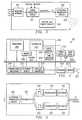
- FIG. 1Bis a pictorial representation of the front panel of data processing unit 102 .
- the front panelincludes an infrared window 108 for receiving signals from remote control unit 106 and for transmitting infrared signals.
- the front panelalso includes an acoustical transducer window 109 for receiving control signals from one or more wireless control devices, as will be described below.
- Data processing unit 102may transmit infrared signals to be reflected off objects or surfaces, allowing data processing unit 102 to automatically control television 104 and other infrared remote controlled devices.
- Volume control 110permits adjustment of the sound level emanating from a speaker within data processing unit 102 or from television 104 .
- a plurality of light-emitting diode (LED) indicators 112provide an indication to the user of when data processing unit 102 is on, whether the user has messages, whether the modem/phone line is in use, or whether data processing unit 102 requires service.
- LEDlight-emitting diode
- Figure 1Cis a pictorial representation of the rear panel of data processing unit 102 .
- a three wire (ground included) insulated power cord 114passes through the rear panel.
- Standard telephone jacks 116 and 118 on the rear panelprovide an input to a modem from the phone line and an output to a handset (not shown).
- the real panelalso provides a standard computer keyboard connection 120 , mouse port 122 , computer monitor port 124 , printer port 126 , and an additional serial port 128 . These connections may be employed to allow data processing unit 102 to operate in the manner of a conventional personal computer.
- Game port 130 on the rear panelprovides a wire connection for a joystick or other gaming control device (glove, etc.) although, as noted above and as described below, the front panel of the device includes the window 109 for receiving acoustic control signals.
- Infrared extension jack 132allows a cabled infrared LED to be utilised to transmit infrared signals.
- Microphone jack 134allows an external microphone to be connected to data processing unit 102 .
- Video connection 136a standard coaxial cable connector, connects to the video-in terminal of television 104 or a video cassette recorder (not shown). Left and right audio jacks 138 connect to the corresponding audio-in connectors on television 104 or to a stereo (not shown). If the user has S-Video input, then S-Video connection 140 may be used to connect to television 104 to provide a better picture than the composite signal. If television 104 has no video inputs, an external channel 3/4 modulator (not shown) may be connected in-line with the antenna connection.
- Figure 1Dis a pictorial representation of remote control unit 106 .
- remote control unit 106Similar to a standard telephone keypad, remote control unit 106 includes buttons 142 for Arabic numerals 0 through 9 , the asterisk or "star” symbol (*), and the pound sign (#).
- Remote control unitalso includes "TV” button 144 for selectively viewing television broadcasts and "Web” button 146 for initiating "browsing" of the Internet or "off-line” browsing of the hard drive. For example, pressing "Web” button 146 will cause data processing unit 102 to initiate modem dial-up of the user's Internet service provider and display the start-up screen for an Internet browser.
- a pointing device 147which is preferably a trackpoint or "button” pointing device, is included on remote control unit 106 and allows a user to manipulate a cursor on the display of television 104 .
- "Go” and “Back” buttons 148 and 150respectively, allow a user to select an option or retum to a previous selection.
- "Help” button 151causes context-sensitive help to be displayed or otherwise provided.
- "Menu” button 152causes a context-sensitive menu of options to be displayed, and "Update” button 153 will update the options displayed based on the user's input, while home button 154 allows the user to return to a default display of options.
- "PgUp” and “PgDn” buttons 156 and 158allows the user to change the context of the display in display-sized blocks rather than by scrolling.
- the message button 160allows the user to retrieve messages.
- an infrared keyboard(not shown) with an integral pointing device may be used to control data processing unit 102 .
- the keyboardmay communicate with the data processing unit via control commands impressed upon an ultrasonic carrier signal.
- the integral pointing deviceis preferably a trackpoint or button type of pointing device.
- a wired keyboard(also not shown) may also be used through keyboard connection 120 , and a wired pointing device such as a mouse or trackball may be used through mouse port 122 .
- the active devicemay lock out all others until a prescribed period of inactivity has passed.
- a representative wireless control deviceis a joystick, which is illustrated in simplified form in Figure 2.
- a joystickis useful for inputting information into a computer or to control the movement of a figure or object in a video game.
- Joystick 310includes a handle 312 pivotally mounted in a swivel 313 in an upper housing portion 314 .
- the upper housing 314is attached to a lower housing 316 .
- the handle 312facilitates manual input of co-ordinate information to the computer or video game with the handle being movable to a position in two orthogonal directions to control the input of such co-ordinate information.
- handle 312is adapted to be manually manipulated to move or pivot in any direction about the swivel 313 to produce different movements of the control 317 , which thus moves in an X-Y co-ordinate plane.
- control 317makes contact with switches 318, 320, 322 and 324, to produce digital information.
- the switchesare spaced 90 degrees apart, representing movement of the handle 312 in the + x, - x, + y and - y directions of the X-Y co-ordinate plane.
- the actual joystickdoes not use physical "switch" devices such as represented in Figure 2 ; rather, the joystick position is determined using a pair of variable resistors (or perhaps capacitors) set up in a gimbel mechanism.
- the two variable resistorsmeasure the X and Y position of the joystick and generate X and Y values that are proportional to the joystick position in the X-Y plane. These latter signals are then sent to the computer.
- the joysticktypically includes operator-actual firing buttons 329 and 330 which, when pressed, control or activate other switches which send signals to the computer or game to initiate an event. Buttons 329 and 330 thus generate action control signals for effecting an event or action on the display screen.
- FIG 3is a simplified schematic diagram of the electrical circuitry of the joystick of Figure 2 .
- Resistor network 332represents the pair of variable resistors discussed above.
- the resistor network outputis supplied to an signal processing circuit 334 , which also receives the outputs of the firing buttons 329 and 330 .
- Circuit 334outputs a pulse signal with a given number of bits (e.g., 12 bits) representing the X-Y position value and a given number of bits (e.g., 4 bits) representing the button values.
- the pulse signalmay also include a parity bit.
- the pulse signalis then supplied to an ultrasonic transducer circuit 336 , in which it is used to modulate an ultrasonic carrier signal generated by a ceramic transducer 338 .
- the circuitalso includes a suitable battery and associated circuitry 340 for powering the device.
- manipulation of the joystick handleprovides corresponding X-Y movement of a cursor, graphical pointer or other game display element on the display device which, in this case, is the television monitor.
- the display deviceis a conventional computer monitor.
- actuation of a control button on the joystickcauses some display element to change state.
- the joysticks 101 and 103are used in conjunction with some program source, such as a computer game or other software application running on the machine.
- the X-Y position control signals and the action control signalsare impressed upon an ultrasonic carrier signal by an ultrasonic transducer in the joystick.
- the transduceris preferably a piece of ceramic that vibrates at a first carrier frequency. It is modulated by the X-Y position control signals and/or any action control signals generated by actuation of the buttons.
- control signalsare then transmitted over the air to the base unit, or the base unit may poll the device to determine the state of the various control elements.
- a corresponding control device for use by another personoperates in a similar manner, except that the transducer in such device is tuned to another carrier frequency so that the pair of devices may be used simultaneously.
- each of the wireless remote control devicesincludes an appropriate acoustical transducer tuned to a different carrier frequency such that the pair of control devices may be used simultaneously to control graphical elements on the display.
- the acoustical transducergenerates an ultrasonic carrier so that the control signals are inaudible.
- the joystick devices 101 and 103may be used by two players simultaneously in order to effect changes to the display without interference with each other or with any infrared signals generated by the remote control unit 106 .
- data processing unit 102includes a motherboard 202 containing a processor 204 and memory 206 connected to system bus 280 .
- Processor 205is preferably at least a 486 class processor operating at or above 100 MHz.
- Memory 206may include cache memory and/or video RAM.
- Processor 205 , memory 206 , and system bus 208operate in the same manner as corresponding components in a conventional data processing system.
- Video/TV converter 210located on motherboard 202 and connected to system bus 208 , generates computer video signals for computer monitors, a composite television signal, and an S-Video signal.
- the functionality of Video/TV converter 210may be achieved, for example, through a Trident TVG 9685 video chip in conjunction with an Analogue Devices AD 722 converter chip.
- Video/TV converter 210may require loading of special operating system device drivers.
- Keyboard/remote control interface unit 212 on motherboard 202receives keyboard codes through controller 214 , regardless of whether a wired keyboard/pointing device or an infrared keyboard/remote control is being employed.
- Infrared remote control unit 106transmits signals which are ultimately sent to the serial port as control signals generated by conventional mouse or pointing device movements. Two buttons on remote control unit 106 are interpreted identically to the two buttons on a conventional mouse. while the remainder of the buttons transmit signals corresponding to keystrokes on an infrared keyboard. Thus, remote control unit 106 has a subset of the function provided by an infrared keyboard.
- Connectors/indicators 216 on motherboard 202provide some of the connections and indicators on data processing unit 102 described above. Other connections are associated with and found on other components. For example, telephone jacks 116 and 118 are located on modem 222 . The power indicator within connectors/indicators 216 is controlled by controller 214 . External to motherboard 202 in the depicted example are power supply 218 , hard drive 220 , modem 222 and speaker 224 .
- Power supply 218is a conventional power supply except that it receives a control signal from controller 214 which effects shut down of all power to motherboard 202 , hard drive 220 and modem 222 . In some recovery situations, removing power and rebooting is the only guaranteed method of resetting all of these devices to a known state. Thus, power supply 218 , in response to a signal from controller 214 , is capable of powering down and restarting data processing unit 102 .
- Controller 214is preferably one or more of the 805 x family controllers. Controller 214 receives and processes input from infrared remote control 106 , infrared keyboard, wired keyboard. or wired mouse. When one keyboard or pointing device is used, all others are locked out (ignored) until none have been active for a prescribed period. Then the first keyboard or pointing device to generate activity locks out all others. Controller 214 also directly controls all LED indicators except that indicating modem use. As part of the failure recovery system, controller 214 specifies the boot sector selection during any power off-on cycle.
- Hard drive 220contains operating system and applications software for data processing unit 102 , which preferably includes IBM DOS 7.0 , a product of International Business Machines Corporation in Armonk, New York; an operating system 221 such as Windows 3.1 (or higher), a product of Microsoft Corporation in Redmond. Washington; and a browser 223 such as Netscape Navigator (Version 1.0 or higher), a product of Netscape Communications Corporation in Mountain View, California.
- IBM DOS 7.0a product of International Business Machines Corporation in Armonk, New York
- an operating system 221such as Windows 3.1 (or higher), a product of Microsoft Corporation in Redmond. Washington
- a browser 223such as Netscape Navigator (Version 1.0 or higher), a product of Netscape Communications Corporation in Mountain View, California.
- Software on the hard drive 220may also support an SMTP mechanism to provide electronic mail, an FTP mechanism to facilitate file transfers from Internet FTP sites, and other TCP/IP mechanisms, all in a known manner.
- SMTPelectronic mail
- FTPfile transfers from Internet FTP sites
- TCP/IPTransmission Control Protocol/IP
- Modem 222may be any suitable modem used in conventional data processing systems, but is preferably a 33.6 kbps modem supporting the V. 42 bis, V. 34 , V. 17 Fax. MNP 1-5 , and AT command sets. To maintain the slim height of data processing system 102 , modem 222 is preferably inserted into a slot mounted sideways on motherboard 202 . Modem 222 is connected to a physical communication link 227 , which, in turn, in connected or connectable to the Internet (not shown).
- Data processing unitalso includes circuitry for receiving the acoustical control signals generated by the control devices 101 and 103 .
- This circuitryis illustrated in Figure 5 .
- the receiverincludes an ultrasonic transducer circuit 350 that drives a selective preamplifier 352 .
- the acoustical signals received by the transducerare converted to electrical waveforms, amplified by preamplifier 352 , and then supplied to a pair of bandpass filters 354 and 356 .
- Filter 354is tuned to the carrier frequency of control device 101 and filter 356 is tuned to the carrier frequency of control device 103 .
- filter 354passes the signals generated by device 101 and filter 356 passes the signals generated by device 103 , but not vice versa.
- the filter outputsare then passed through a pair of demodulators 358 and 360 , which serve to remove the carrier signals.
- the demodulator outputsare then passed through decoder circuits 362 and 364 to generate the decoded display control signals used to control the display device.
- the bandpass filters, demodulators and decoder circuits, or any of themmay be implemented in whole or in part in hardware or in software.
- the data processing systemmay be a personal computer such as a desktop or notebook computer, e.g., an IBM( or IBM-compatible machine running under the OS/2( operating system, an IBM ThinkPad( machine, or some other Intel x86 or Pentium(-based computer running Windows 3.1 or greater operating system.
- a personal computersuch as a desktop or notebook computer, e.g., an IBM( or IBM-compatible machine running under the OS/2( operating system, an IBM ThinkPad( machine, or some other Intel x86 or Pentium(-based computer running Windows 3.1 or greater operating system.
- the present inventionprovides many useful advantages.
- the number of control connectors and the likeis reduced. thus making the use of the Web appliance far more practical and enjoyable for inexperienced computer users.
- the wireless control devicesoperate using acoustic energy as opposed to infrared light, and thus they consume far less power than conventional infrared control devices.
- the control devicesadvantageously use existing infrared-type electronics, but replace the infrared elements (LED's and phototransistors) with ultrasound transducers tuned to different carrier frequencies.
- the large amplitude signals used to drive the infrared LED'sare sufficient to generate ultrasonic variations of the same modulated signal.
- the phototransistoralready goes into a selective preamplifier at the receiving circuitry, and thus, the control signals do not need to be otherwise processed in any different manner.
- inventive systemneed not be limited to merely a pair of handheld wireless devices.
- the systemmay include a plurality of such handheld devices, each "tuned" to a separate carrier frequency. Some of the plurality of devices may be joysticks, while still others are different types of control devices such as gaming gloves, pointing devices, mice, etc.
- inventive techniquesmay be useful in facilitating simultaneous multi-user control of a display device in the context of more than just two participants.
- the present inventionbe implemented merely as a game control system, as the display device and associated control devices may be used for any purpose where it is required or desired to control display of and/or provide interactive information to multiple users.
- the inventionhas many other applications, e.g., for interactive sampling, audience participation, polling and the like, and any other uses where it is desired to provide multiple user interaction with a display device.
- Another application of the present inventionis to enable play of interactive games over a computer network, such as the Internet or World Wide Web.
- a computer networksuch as the Internet or World Wide Web.
- interactive game display informationwould be downloaded from a server.
- One or more playerswould then use the wireless control devices in the manner described to manipulate one or more game elements, preferably as the active connection over the network is maintained.
- one usercould be located at one computer and play a second user located at a second computer.
- the inventionalso comprises an input control device for use in a display control system for controlling a display of a data processing system, the display control system including a receiver, wherein the input control device comprises:
- the inventionalso comprises a receiver for use in a display control system for controlling a display of a data processing system, the display control system including at least a pair of wireless control devices that generate respective first and second position control signals imposed upon first and second ultrasonic carrier signals of different frequencies.
- the receivercomprising:
- the signal processing meansmay include a computer program executed by the data processing system.
Landscapes
- Engineering & Computer Science (AREA)
- Multimedia (AREA)
- Human Computer Interaction (AREA)
- Physics & Mathematics (AREA)
- Theoretical Computer Science (AREA)
- General Engineering & Computer Science (AREA)
- General Physics & Mathematics (AREA)
- Signal Processing (AREA)
- Computer Networks & Wireless Communication (AREA)
- Acoustics & Sound (AREA)
- Automation & Control Theory (AREA)
- Position Input By Displaying (AREA)
- Selective Calling Equipment (AREA)
- Measurement Of Velocity Or Position Using Acoustic Or Ultrasonic Waves (AREA)
Abstract
Description
The present invention relates in general to a method and system for dataprocessing and in particular to an improved method and system of userinterface to a data processing system. Still more particularly, the presentinvention relates to an improved method and system for simultaneousoperation of multiple display control devices, such as a pair of joysticks.
There has been great interest in providing Internet access at minimal economiccost. While most computers now are pre-configured for Internet access, asignificant percentage of households still do not have a personal computer.Thus, it has now been proposed to provide a data processing system that,much like a VCR, may be connected to a television set and used in lieu of apersonal computer to provide World Wide Web access through a conventionalremote control device associated with the system unit. Such a system enablesthe television to become, in effect, a "Web" appliance. The viewer can rapidlyswitch between conventional television and Internet access using the remotecontrol unit. All of the conventional "Internet" access tools and navigationalfunctions are preferably "built-in" to the system and thus hidden to the user.
The remote control unit used to control the Web appliance is battery-poweredand will typically include an infrared source, such as a light emitting diode(LED), which cooperates with a phototransistor in a receiver unit to effect thetransfer of control signals for the appliance. An infrared control unit,however, is unsuitable for use in providing control of computer games, whichuse joysticks or glove control devices, because many of these games involvemultiple players. Multiple infrared remote devices interfere with each otherwhen used in the same physical environment.
The infrared source also causes a significant power drain when usedcontinuously, thus reducing battery life. As a result, it has been necessary tohard-wire the game control devices directly into the computer. Such wiring,however, is quite cumbersome and does not present an acceptable solution.This is especially true in the context of a Web appliance, where it is desired toreduce the complexity of the device as well as the machine interactionrequired by the user.
It is therefore a principal object of the present invention to provide a methodand system for wireless display control in a personal computer.
It is still another principal object to provide a control system for computergames that includes a pair of wireless remote control devices adapted to beused by two different people simultaneously and without interference.
It is a further object of the invention to enhance the control of a dataprocessing system using ultrasonic wireless control devices "tuned" todifferent, non-interfering frequencies.
Another object of the present invention is to enhance the entertainment valueof a computer system by obviating wired control devices.
Still another object of the invention is to provide a simple and cost-effectivealternative to infrared control devices in a personal computer.
Yet another more general object is to provide an improved method and systemof user interface within a data processing system.
These and other objects are provided in a system for controlling a display of adata processing system. The system comprises first and second wirelessposition control devices, such as a pair of joystick controls, and a control baseunit associated with a data processing system, such as a personal computer.The first wireless position control device includes an acoustical transducer fortransmitting a first ultrasonic carrier signal upon which X-Y position and/orother action control signals generated by the device are imposed. A secondwireless position control device includes an acoustical transducer fortransmitting a second ultrasonic carrier signal upon which X-Y position and/orother action control signals generated by the second control device areimposed. The first and second ultrasonic carrier signals have differentfrequencies that are non-interfering within the physical constraints of thesystem environment or the display characteristics of the screen window. Thecontrol base associated with the data processing system includes appropriatecircuitry for receiving and differentiating the first and second ultrasonic carriersignals to generate decoded X-Y position control signals and/or other actioncontrol signals. The decoded X-Y position control signals and/or the actioncontrol signals are then used to drive the display device. In particular, theposition control and action control signals received from the first wirelessposition control device cause a first action and/or event on the display. whilethe position control and action control signals received from the secondwireless position control device cause a second action and/or event on the display. The first and second actions or events facilitate the play of somemultiplayer, interactive game or exercise.
In accordance with a more general aspect of the invention, a method ofcontrolling a display of a data processing system is also provided. Accordingto the method. first and second ultrasonic carrier signals upon which controlsignals are imposed are transmitted from respective first and second handheld.wireless control devices. Each of the devices is battery-powered. Preferably,the control signals include X-Y position control signals, action control signals,or both. At a receiver. the first and second ultrasonic carrier signals aredifferentiated and processed to generate display control signals. The displaycontrol signals are then used to drive a display device of a data processingsystem. In this manner, a pair of users of the first and second wireless controldevices may interact with each other without interference.
The foregoing has outlined some of the more pertinent objects and features ofthe present invention. These objects should be construed to be merelyillustrative of some of the more prominent features and applications of theinvention. Many other beneficial results can be attained by applying thedisclosed invention in a different manner or modifying the invention as will bedescribed. Accordingly. other objects and a fuller understanding of theinvention may be had by referring to the following.
The novel features believed characteristic of the invention are set forth in theappended claims.
The invention itself however, as well as a preferred mode of use, furtherobjects and advantages thereof, will best be understood by reference to thefollowing detailed description of an illustrative embodiment when read inconjunction with the accompanying drawings. wherein:
A representative computer environment in which the present invention may beimplemented is a "Web" appliance.
At the outset, although the invention is illustrated in the context of a "Web"appliance, the features of the invention may be implemented in any dataprocessing system, or even in a standalone gaming device, irrespective of theactual computer, network or other system environment.
A representative data processing system or so-called "Web appliance" isillustrated inFigures 1A-1D and4.Figure 1A is a pictorial representation ofthe data processing system as a whole.Data processing system 100 in thedepicted example provides, with minimal economic costs for hardware to theuser, access to the Internet.Data processing system 100 includes adataprocessing unit 102.Data processing unit 102 is preferably sized to fit intypical entertainment centres and provides all required functionality, which isconventionally found in personal computers, to enable a user to "browse" theInternet. Additionally,data processing unit 102 may provide other commonfunctions such as serving as an answering machine or receiving facsimiletransmissions.
According to the present invention, and as seen inFigure 1A, one or morewirelessremote control devices remote control devices devices devices remote control unit 106, any infrared keyboard, orother control device.
Figure 1B is a pictorial representation of the front panel ofdata processingunit 102. The front panel includes aninfrared window 108 for receivingsignals fromremote control unit 106 and for transmitting infrared signals.The front panel also includes anacoustical transducer window 109 forreceiving control signals from one or more wireless control devices, as will bedescribed below.
Figure 1C is a pictorial representation of the rear panel ofdata processing unit 102. A three wire (ground included)insulated power cord 114 passes throughthe rear panel.Standard telephone jacks computer keyboardconnection 120,mouse port 122,computer monitor port 124,printer port 126,and an additionalserial port 128. These connections may be employed toallowdata processing unit 102 to operate in the manner of a conventionalpersonal computer.Game port 130 on the rear panel provides a wireconnection for a joystick or other gaming control device (glove, etc.) although,as noted above and as described below, the front panel of the device includesthewindow 109 for receiving acoustic control signals.Infrared extension jack 132 allows a cabled infrared LED to be utilised to transmit infrared signals.Microphone jack 134 allows an external microphone to be connected todataprocessing unit 102.
Figure1D is a pictorial representation ofremote control unit 106. Similar to astandard telephone keypad,remote control unit 106 includesbuttons 142 forArabic numerals 0 through9, the asterisk or "star" symbol (*), and the poundsign (#). Remote control unit also includes "TV"button 144 for selectivelyviewing television broadcasts and "Web"button 146 for initiating "browsing"of the Internet or "off-line" browsing of the hard drive. For example, pressing"Web"button 146 will causedata processing unit 102 to initiate modemdial-up of the user's Internet service provider and display the start-up screenfor an Internet browser.
Apointing device 147, which is preferably a trackpoint or "button" pointingdevice, is included onremote control unit 106 and allows a user to manipulatea cursor on the display oftelevision 104. "Go" and "Back"buttons button 151 causes context-sensitive help to be displayed orotherwise provided.
"Menu"button 152 causes a context-sensitive menu of options to bedisplayed, and "Update"button 153 will update the options displayed based onthe user's input, whilehome button 154 allows the user to return to a defaultdisplay of options. "PgUp" and "PgDn"buttons message button 160 allows the user to retrieve messages.
In addition toremote control unit 106, an infrared keyboard (not shown) withan integral pointing device may be used to controldata processing unit 102.The keyboard may communicate with the data processing unit via controlcommands impressed upon an ultrasonic carrier signal. The integral pointingdevice is preferably a trackpoint or button type of pointing device. A wiredkeyboard (also not shown) may also be used throughkeyboard connection 120, and a wired pointing device such as a mouse or trackball may be usedthroughmouse port 122. When a user has one or more of theremote controlunit 106, infrared keyboard, wired keyboard and/or wired pointing deviceoperable, the active device may lock out all others until a prescribed period ofinactivity has passed.
As noted above, one or more wirelessremote control devices handle 312 pivotally mounted in aswivel 313 in anupper housing portion314.
The upper housing314 is attached to alower housing 316. Thehandle 312facilitates manual input of co-ordinate information to the computer or videogame with the handle being movable to a position in two orthogonal directionsto control the input of such co-ordinate information. To this end, handle312is adapted to be manually manipulated to move or pivot in any direction abouttheswivel 313 to produce different movements of thecontrol 317, which thusmoves in an X-Y co-ordinate plane. When the handle is manipulated,control 317 makes contact withswitches handle 312 in the + x, - x, + y and - y directions of the X-Yco-ordinate plane. Preferably, the actual joystick does not use physical"switch" devices such as represented inFigure 2; rather, the joystick positionis determined using a pair of variable resistors (or perhaps capacitors) set up ina gimbel mechanism. The two variable resistors measure the X and Y positionof the joystick and generate X and Y values that are proportional to thejoystick position in the X-Y plane. These latter signals are then sent to thecomputer. The joystick typically includes operator-actual firing buttons Buttons
Figure 3 is a simplified schematic diagram of the electrical circuitry of thejoystick ofFigure 2.Resistor network 332 represents the pair of variableresistors discussed above.
The resistor network output is supplied to ansignal processing circuit 334,which also receives the outputs of the firingbuttons Circuit 334outputs a pulse signal with a given number of bits (e.g., 12 bits) representingthe X-Y position value and a given number of bits (e.g., 4 bits) representingthe button values. The pulse signal may also include a parity bit. The pulsesignal is then supplied to anultrasonic transducer circuit 336, in which it isused to modulate an ultrasonic carrier signal generated by aceramictransducer 338. The circuit also includes a suitable battery and associatedcircuitry 340 for powering the device.
In operation, manipulation of the joystick handle provides corresponding X-Ymovement of a cursor, graphical pointer or other game display element on thedisplay device which, in this case, is the television monitor. Alternatively, thedisplay device is a conventional computer monitor. Likewise, actuation of acontrol button on the joystick causes some display element to change state.Typically, thejoysticks
The X-Y position control signals and the action control signals are impressedupon an ultrasonic carrier signal by an ultrasonic transducer in the joystick.The transducer is preferably a piece of ceramic that vibrates at a first carrierfrequency. It is modulated by the X-Y position control signals and/or anyaction control signals generated by actuation of the buttons.
The control signals are then transmitted over the air to the base unit, or thebase unit may poll the device to determine the state of the various controlelements. A corresponding control device for use by another person operatesin a similar manner, except that the transducer in such device is tuned toanother carrier frequency so that the pair of devices may be usedsimultaneously.
Thus, in accordance with the present invention, each of the wireless remotecontrol devices includes an appropriate acoustical transducer tuned to adifferent carrier frequency such that the pair of control devices may be usedsimultaneously to control graphical elements on the display. Preferably, theacoustical transducer generates an ultrasonic carrier so that the control signalsare inaudible. Thus, one of ordinary skill in the art will appreciate that thejoystick devices remote control unit 106.
Referring now toFigure 4, a block diagram for the major components ofdataprocessing unit 102 is portrayed. As with conventional personal computers,data processing unit 102 includes amotherboard 202 containing aprocessor 204 andmemory 206 connected to system bus280. Processor205 ispreferably at least a486 class processor operating at or above100 MHz.Memory 206 may include cache memory and/or video RAM. Processor205,memory 206, andsystem bus 208 operate in the same manner ascorresponding components in a conventional data processing system.
Video/TV converter 210, located onmotherboard 202 and connected tosystem bus 208, generates computer video signals for computer monitors, acomposite television signal, and an S-Video signal. The functionality ofVideo/TV converter 210 may be achieved, for example, through a TridentTVG9685 video chip in conjunction with an Analogue Devices AD722converter chip. Video/TV converter 210 may require loading of specialoperating system device drivers.
Keyboard/remotecontrol interface unit 212 onmotherboard 202 receiveskeyboard codes throughcontroller 214, regardless of whether a wiredkeyboard/pointing device or an infrared keyboard/remote control is beingemployed. Infraredremote control unit 106 transmits signals which areultimately sent to the serial port as control signals generated by conventionalmouse or pointing device movements. Two buttons onremote control unit 106 are interpreted identically to the two buttons on a conventional mouse.while the remainder of the buttons transmit signals corresponding tokeystrokes on an infrared keyboard. Thus,remote control unit 106 has asubset of the function provided by an infrared keyboard.
Connectors/indicators 216 onmotherboard 202 provide some of theconnections and indicators ondata processing unit 102 described above.Other connections are associated with and found on other components. Forexample,telephone jacks modem 222. The powerindicator within connectors/indicators 216 is controlled bycontroller 214.External tomotherboard 202 in the depicted example arepower supply 218,hard drive 220,modem 222 andspeaker 224.
Software on thehard drive 220 may also support an SMTP mechanism toprovide electronic mail, an FTP mechanism to facilitate file transfers fromInternet FTP sites, and other TCP/IP mechanisms, all in a known manner. Ofcourse, the software identified above is merely representative, as other knownprograms may be used in the alternative or by way of addition.
Data processing unit also includes circuitry for receiving the acoustical controlsignals generated by thecontrol devices ultrasonictransducer circuit 350 that drives aselective preamplifier 352. The acousticalsignals received by the transducer are converted to electrical waveforms,amplified bypreamplifier 352, and then supplied to a pair ofbandpass filters Filter 354 is tuned to the carrier frequency ofcontrol device 101andfilter 356 is tuned to the carrier frequency ofcontrol device 103. Thus,filter354 passes the signals generated bydevice 101 and filter356 passes thesignals generated bydevice 103, but not vice versa.
The filter outputs are then passed through a pair ofdemodulators decoder circuits
Those skilled in the art will further recognise that the components depicted inFigures 1A-1D and described above may be varied for specific applications orembodiments. Such variations in which the present invention may beimplemented are considered to be within the scope of the present invention.Thus. for example. the data processing system may be a personal computersuch as a desktop or notebook computer, e.g., an IBM( or IBM-compatiblemachine running under the OS/2( operating system, an IBM ThinkPad(machine, or some other Intel x86 or Pentium(-based computer runningWindows 3.1 or greater operating system.
It should thus be appreciated that the present invention provides many usefuladvantages. By using a pair of wireless control devices. the number of controlconnectors and the like is reduced. thus making the use of the Web appliancefar more practical and enjoyable for inexperienced computer users. Thewireless control devices operate using acoustic energy as opposed to infraredlight, and thus they consume far less power than conventional infrared controldevices.
This is highly advantageous because such game control devices are far moreoften in the "on" position as opposed to being "off." Infrared devices, on thecontrary, are rarely used and thus battery conservation is not a majoroperational criteria. The use of ultrasonic transducers in a pair of devicesallows multiple devices to be used simultaneously without interference witheach other or to any other infrared control device.
The control devices advantageously use existing infrared-type electronics, butreplace the infrared elements (LED's and phototransistors) with ultrasoundtransducers tuned to different carrier frequencies. The large amplitude signalsused to drive the infrared LED's (in a conventional remote control unit) aresufficient to generate ultrasonic variations of the same modulated signal.Moreover, the phototransistor already goes into a selective preamplifier at thereceiving circuitry, and thus, the control signals do not need to be otherwiseprocessed in any different manner.
Of course. one of ordinary skill will recognise that the inventive system neednot be limited to merely a pair of handheld wireless devices. The system mayinclude a plurality of such handheld devices, each "tuned" to a separate carrierfrequency. Some of the plurality of devices may be joysticks, while stillothers are different types of control devices such as gaming gloves, pointingdevices, mice, etc. Thus, the inventive techniques may be useful in facilitatingsimultaneous multi-user control of a display device in the context of more thanjust two participants. Moreover, there is no requirement that the presentinvention be implemented merely as a game control system, as the displaydevice and associated control devices may be used for any purpose where it is required or desired to control display of and/or provide interactive informationto multiple users. Thus, the invention has many other applications, e.g., forinteractive sampling, audience participation, polling and the like, and anyother uses where it is desired to provide multiple user interaction with adisplay device.
Another application of the present invention is to enable play of interactivegames over a computer network, such as the Internet or World Wide Web.Once the data processing system described above is connected to such anetwork, interactive game display information would be downloaded from aserver. One or more players would then use the wireless control devices in themanner described to manipulate one or more game elements, preferably as theactive connection over the network is maintained. Alternatively, one usercould be located at one computer and play a second user located at a secondcomputer.
The invention also comprises an input control device for use in a displaycontrol system for controlling a display of a data processing system, thedisplay control system including a receiver, wherein the input control devicecomprises:
The invention also comprises a receiver for use in a display control system forcontrolling a display of a data processing system, the display control systemincluding at least a pair of wireless control devices that generate respectivefirst and second position control signals imposed upon first and secondultrasonic carrier signals of different frequencies. the receiver comprising:
In the receiver the signal processing means may include a computer programexecuted by the data processing system.
While the invention has been particularly shown and described with referenceto a preferred embodiment, it will be understood by those skilled in the art thatvarious changes in form and detail may be made therein without departingfrom the scope of the invention as defined in the claims.
Claims (10)
- Apparatus for controlling a display device (104) of a data processingsystem (100), comprising:a first wireless input device (101) including means for transmitting a firstacoustical or ultrasonic carrier signal upon which first control signals areimposed:a second wireless input device (103) including means for transmitting asecond acoustical or ultrasonic carrier signal upon which second controlsignals are imposed. the first and second acoustical carrier signals havingdifferent frequencies;a receiver (1020) associated with the data processing system and includingmeans for receiving and differentiating the first and second acoustical carriersignals to generate first and second display control signals; andmeans responsive (350) to the first and second display control signals forcontrolling the display device.
- The apparatus of Claim1 wherein either or both the first or second inputdevices (101,103) is a joystick.
- The apparatus of Claim2 wherein the first control signals include X-Yposition control signals for controlling an X-Y position of a screen element onthe display device (104) and/or include action control signals for effecting anevent on the display device (104).
- The apparatus of Claim1 wherein the first and second input devices arebattery-powered.
- The apparatus of Claim1 wherein the means for transmitting controlsignals of the first and/or second wireless input device is a ceramic transducer.
- The apparatus of Claim1 wherein the means for differentiating the firstand second acoustical or ultrasonic carrier signals includes a first bandpassfilter (354) tuned to the first acoustical or ultrasonic carrier signal and asecond bandpass filter (356) tuned to the second acoustical or ultrasoniccarrier signal.
- A method of controlling a data processing system, comprising the steps of:transmitting a first ultrasonic carrier signal upon which first control signals areimposed;transmitting a second ultrasonic carrier signal upon which second controlsignals are imposed, the first and second ultrasonic carrier signals havingdifferent frequencies;receiving and differentiating the first and second ultrasonic carrier signals togenerate decoded control signals; andsending the decoded control signals to the data processing system(100).
- A method of controlling a display (104) of a data processing system (100)connected to a computer network having a server, comprising the steps of:establishing an active connection between the data processing system and theserver;downloading information to the data processing system to cause a first gameelement to be output on the display (104);having at least a first user of the data processing system (100) use a firstwireless control device (101) for transmitting a first ultrasonic carrier signalupon which first control signals are imposed;receiving and differentiating the first ultrasonic carrier signal to generatedecoded first display control signals; anddriving the display (104) using the decoded first display control signals whilethe active connection is maintained to thereby manipulate the first gameelement.
- The method as described in Claim8 further including the steps of:having a second user of the data processing system use a second wirelesscontrol device (103) for transmitting a second ultrasonic carrier signal uponwhich second control signals are imposed;receiving and differentiating the second ultrasonic carrier signal to generatedecoded second display control signals; anddriving the display (104) using the decoded second display control signalswhile the active connection is maintained to thereby manipulate a secondgame element.
- An input control device (101) for a data processing system (100), whereinthe input control device comprises:a control element (312);means (318,320,322,324) responsive to activation of the control element (312)for generating control signals;means for transmitting an acoustical or ultrasonic carrier signal modulated bythe control signals to thereby control the data processing system.
Applications Claiming Priority (2)
| Application Number | Priority Date | Filing Date | Title |
|---|---|---|---|
| US824532 | 1997-03-26 | ||
| US08/824,532US6144367A (en) | 1997-03-26 | 1997-03-26 | Method and system for simultaneous operation of multiple handheld control devices in a data processing system |
Publications (2)
| Publication Number | Publication Date |
|---|---|
| EP0867798A2true EP0867798A2 (en) | 1998-09-30 |
| EP0867798A3 EP0867798A3 (en) | 2006-04-19 |
Family
ID=25241639
Family Applications (1)
| Application Number | Title | Priority Date | Filing Date |
|---|---|---|---|
| EP98301693AWithdrawnEP0867798A3 (en) | 1997-03-26 | 1998-03-09 | Data processing system user interface |
Country Status (6)
| Country | Link |
|---|---|
| US (1) | US6144367A (en) |
| EP (1) | EP0867798A3 (en) |
| JP (1) | JPH10301707A (en) |
| KR (1) | KR100323623B1 (en) |
| CN (1) | CN1155877C (en) |
| TW (1) | TW366465B (en) |
Cited By (21)
| Publication number | Priority date | Publication date | Assignee | Title |
|---|---|---|---|---|
| US6762750B2 (en) | 1999-06-24 | 2004-07-13 | Johan Ullman | Input device for a computer and a grip arrangement for such a device |
| WO2006121896A3 (en)* | 2005-05-05 | 2007-06-28 | Sony Computer Entertainment Inc | Microphone array based selective sound source listening and video game control |
| US7803050B2 (en) | 2002-07-27 | 2010-09-28 | Sony Computer Entertainment Inc. | Tracking device with sound emitter for use in obtaining information for controlling game program execution |
| US7850526B2 (en) | 2002-07-27 | 2010-12-14 | Sony Computer Entertainment America Inc. | System for tracking user manipulations within an environment |
| US7854655B2 (en) | 2002-07-27 | 2010-12-21 | Sony Computer Entertainment America Inc. | Obtaining input for controlling execution of a game program |
| US7874917B2 (en) | 2003-09-15 | 2011-01-25 | Sony Computer Entertainment Inc. | Methods and systems for enabling depth and direction detection when interfacing with a computer program |
| US7918733B2 (en) | 2002-07-27 | 2011-04-05 | Sony Computer Entertainment America Inc. | Multi-input game control mixer |
| US8139793B2 (en) | 2003-08-27 | 2012-03-20 | Sony Computer Entertainment Inc. | Methods and apparatus for capturing audio signals based on a visual image |
| US8160269B2 (en) | 2003-08-27 | 2012-04-17 | Sony Computer Entertainment Inc. | Methods and apparatuses for adjusting a listening area for capturing sounds |
| US8233642B2 (en) | 2003-08-27 | 2012-07-31 | Sony Computer Entertainment Inc. | Methods and apparatuses for capturing an audio signal based on a location of the signal |
| US8310656B2 (en) | 2006-09-28 | 2012-11-13 | Sony Computer Entertainment America Llc | Mapping movements of a hand-held controller to the two-dimensional image plane of a display screen |
| US8570378B2 (en) | 2002-07-27 | 2013-10-29 | Sony Computer Entertainment Inc. | Method and apparatus for tracking three-dimensional movements of an object using a depth sensing camera |
| US8686939B2 (en) | 2002-07-27 | 2014-04-01 | Sony Computer Entertainment Inc. | System, method, and apparatus for three-dimensional input control |
| US8781151B2 (en) | 2006-09-28 | 2014-07-15 | Sony Computer Entertainment Inc. | Object detection using video input combined with tilt angle information |
| US8797260B2 (en) | 2002-07-27 | 2014-08-05 | Sony Computer Entertainment Inc. | Inertially trackable hand-held controller |
| US8947347B2 (en) | 2003-08-27 | 2015-02-03 | Sony Computer Entertainment Inc. | Controlling actions in a video game unit |
| WO2015155530A1 (en)* | 2014-04-08 | 2015-10-15 | China Industries Limited | Interactive combat gaming system |
| US9174119B2 (en) | 2002-07-27 | 2015-11-03 | Sony Computer Entertainement America, LLC | Controller for providing inputs to control execution of a program when inputs are combined |
| US9393487B2 (en) | 2002-07-27 | 2016-07-19 | Sony Interactive Entertainment Inc. | Method for mapping movements of a hand-held controller to game commands |
| US10086282B2 (en) | 2002-07-27 | 2018-10-02 | Sony Interactive Entertainment Inc. | Tracking device for use in obtaining information for controlling game program execution |
| USRE48417E1 (en) | 2006-09-28 | 2021-02-02 | Sony Interactive Entertainment Inc. | Object direction using video input combined with tilt angle information |
Families Citing this family (72)
| Publication number | Priority date | Publication date | Assignee | Title |
|---|---|---|---|---|
| CA2248745C (en)* | 1998-02-13 | 2005-08-23 | Arista Interactive Llc | Wireless game control units |
| US6878066B2 (en)* | 1998-02-13 | 2005-04-12 | Freedom Wave Llc | Wireless game control units |
| US20040090423A1 (en)* | 1998-02-27 | 2004-05-13 | Logitech Europe S.A. | Remote controlled video display GUI using 2-directional pointing |
| US7749089B1 (en) | 1999-02-26 | 2010-07-06 | Creative Kingdoms, Llc | Multi-media interactive play system |
| JP3181275B2 (en)* | 1999-07-30 | 2001-07-03 | 株式会社ケイシーイーオー | Competition method and apparatus, recording medium |
| US6761637B2 (en) | 2000-02-22 | 2004-07-13 | Creative Kingdoms, Llc | Method of game play using RFID tracking device |
| US7445550B2 (en) | 2000-02-22 | 2008-11-04 | Creative Kingdoms, Llc | Magical wand and interactive play experience |
| US7878905B2 (en) | 2000-02-22 | 2011-02-01 | Creative Kingdoms, Llc | Multi-layered interactive play experience |
| US7500917B2 (en) | 2000-02-22 | 2009-03-10 | Creative Kingdoms, Llc | Magical wand and interactive play experience |
| US7066781B2 (en) | 2000-10-20 | 2006-06-27 | Denise Chapman Weston | Children's toy with wireless tag/transponder |
| US6722984B1 (en)* | 2000-11-22 | 2004-04-20 | Universal Electronics Inc. | Game controller with parental control functionality |
| US6967566B2 (en) | 2002-04-05 | 2005-11-22 | Creative Kingdoms, Llc | Live-action interactive adventure game |
| US20070066396A1 (en) | 2002-04-05 | 2007-03-22 | Denise Chapman Weston | Retail methods for providing an interactive product to a consumer |
| US7161579B2 (en) | 2002-07-18 | 2007-01-09 | Sony Computer Entertainment Inc. | Hand-held computer interactive device |
| US7646372B2 (en)* | 2003-09-15 | 2010-01-12 | Sony Computer Entertainment Inc. | Methods and systems for enabling direction detection when interfacing with a computer program |
| US7623115B2 (en) | 2002-07-27 | 2009-11-24 | Sony Computer Entertainment Inc. | Method and apparatus for light input device |
| US7809145B2 (en) | 2006-05-04 | 2010-10-05 | Sony Computer Entertainment Inc. | Ultra small microphone array |
| US8073157B2 (en)* | 2003-08-27 | 2011-12-06 | Sony Computer Entertainment Inc. | Methods and apparatus for targeted sound detection and characterization |
| US8019121B2 (en)* | 2002-07-27 | 2011-09-13 | Sony Computer Entertainment Inc. | Method and system for processing intensity from input devices for interfacing with a computer program |
| US9474968B2 (en) | 2002-07-27 | 2016-10-25 | Sony Interactive Entertainment America Llc | Method and system for applying gearing effects to visual tracking |
| US8313380B2 (en) | 2002-07-27 | 2012-11-20 | Sony Computer Entertainment America Llc | Scheme for translating movements of a hand-held controller into inputs for a system |
| US7760248B2 (en) | 2002-07-27 | 2010-07-20 | Sony Computer Entertainment Inc. | Selective sound source listening in conjunction with computer interactive processing |
| US9682319B2 (en) | 2002-07-31 | 2017-06-20 | Sony Interactive Entertainment Inc. | Combiner method for altering game gearing |
| US7674184B2 (en) | 2002-08-01 | 2010-03-09 | Creative Kingdoms, Llc | Interactive water attraction and quest game |
| US9177387B2 (en) | 2003-02-11 | 2015-11-03 | Sony Computer Entertainment Inc. | Method and apparatus for real time motion capture |
| EP1603648A4 (en)* | 2003-03-12 | 2006-05-24 | Mattel Inc | Interactive dvd gaming system |
| US20040185934A1 (en)* | 2003-03-21 | 2004-09-23 | Vision Electronics Co., Ltd. | Game cotroller with an alarm clock |
| US9446319B2 (en) | 2003-03-25 | 2016-09-20 | Mq Gaming, Llc | Interactive gaming toy |
| US20040171346A1 (en)* | 2003-04-14 | 2004-09-02 | Ten Ventures Inc. | Method of Adding Wireless Remote Control to Audio Playback Devices Equipped for Wired Remote Control |
| US8072470B2 (en) | 2003-05-29 | 2011-12-06 | Sony Computer Entertainment Inc. | System and method for providing a real-time three-dimensional interactive environment |
| US20070223732A1 (en)* | 2003-08-27 | 2007-09-27 | Mao Xiao D | Methods and apparatuses for adjusting a visual image based on an audio signal |
| US9573056B2 (en) | 2005-10-26 | 2017-02-21 | Sony Interactive Entertainment Inc. | Expandable control device via hardware attachment |
| US8323106B2 (en) | 2008-05-30 | 2012-12-04 | Sony Computer Entertainment America Llc | Determination of controller three-dimensional location using image analysis and ultrasonic communication |
| US8287373B2 (en)* | 2008-12-05 | 2012-10-16 | Sony Computer Entertainment Inc. | Control device for communicating visual information |
| US10279254B2 (en) | 2005-10-26 | 2019-05-07 | Sony Interactive Entertainment Inc. | Controller having visually trackable object for interfacing with a gaming system |
| US7170420B2 (en)* | 2003-11-13 | 2007-01-30 | James Phifer | Ergonomic television remote control |
| US7663689B2 (en)* | 2004-01-16 | 2010-02-16 | Sony Computer Entertainment Inc. | Method and apparatus for optimizing capture device settings through depth information |
| US20060084504A1 (en)* | 2004-04-30 | 2006-04-20 | Chan Andy K | Wireless communication systems |
| US8547401B2 (en) | 2004-08-19 | 2013-10-01 | Sony Computer Entertainment Inc. | Portable augmented reality device and method |
| US7818910B2 (en)* | 2004-09-29 | 2010-10-26 | The United States Of America As Represented By The Secretary Of The Army | Weapon integrated controller |
| US8086519B2 (en)* | 2004-10-14 | 2011-12-27 | Cfph, Llc | System and method for facilitating a wireless financial transaction |
| US7331857B2 (en)* | 2004-11-03 | 2008-02-19 | Mattel, Inc. | Gaming system |
| US8277297B2 (en) | 2004-11-03 | 2012-10-02 | Mattel, Inc. | Gaming system |
| US20060111183A1 (en)* | 2004-11-03 | 2006-05-25 | Peter Maclver | Remote control |
| US20060111184A1 (en)* | 2004-11-03 | 2006-05-25 | Peter Maclver | Gaming system |
| US7860778B2 (en) | 2004-11-08 | 2010-12-28 | Cfph, Llc | System and method for implementing push technology in a wireless financial transaction |
| CN101030321B (en)* | 2006-03-01 | 2011-05-11 | 松下电器产业株式会社 | Remote controller, video apparatus, remote controlling method and system |
| US8777620B1 (en)* | 2006-08-15 | 2014-07-15 | Triggermaster, Inc. | Firearm trigger pull training system and methods |
| US8556628B1 (en)* | 2006-08-15 | 2013-10-15 | Malcom E. Baxter | Shooting training device |
| US9151564B1 (en) | 2006-08-15 | 2015-10-06 | Triggermaster, Inc. | Firearm trigger pull training system and methods |
| CN101310804B (en)* | 2007-05-25 | 2011-07-27 | 富港电子(昆山)有限公司 | Interactive game device position location system and position location method thereof |
| US8542907B2 (en) | 2007-12-17 | 2013-09-24 | Sony Computer Entertainment America Llc | Dynamic three-dimensional object mapping for user-defined control device |
| CN102016877B (en) | 2008-02-27 | 2014-12-10 | 索尼计算机娱乐美国有限责任公司 | Method for capturing depth data of a scene and applying computer actions |
| US8368753B2 (en)* | 2008-03-17 | 2013-02-05 | Sony Computer Entertainment America Llc | Controller with an integrated depth camera |
| TWI470483B (en)* | 2008-11-12 | 2015-01-21 | Cywee Group Ltd | Controller combination |
| US8400263B2 (en)* | 2008-11-19 | 2013-03-19 | Honda Motor Co., Ltd. | Sliding key fob |
| US8188838B2 (en)* | 2008-11-19 | 2012-05-29 | Honda Motor Co., Ltd. | Sliding key fob |
| US8527657B2 (en) | 2009-03-20 | 2013-09-03 | Sony Computer Entertainment America Llc | Methods and systems for dynamically adjusting update rates in multi-player network gaming |
| US8342963B2 (en) | 2009-04-10 | 2013-01-01 | Sony Computer Entertainment America Inc. | Methods and systems for enabling control of artificial intelligence game characters |
| US8393964B2 (en)* | 2009-05-08 | 2013-03-12 | Sony Computer Entertainment America Llc | Base station for position location |
| US8142288B2 (en)* | 2009-05-08 | 2012-03-27 | Sony Computer Entertainment America Llc | Base station movement detection and compensation |
| KR101033543B1 (en)* | 2009-07-21 | 2011-05-11 | (주)펜앤프리 | Information input system and method using ultrasonic signals |
| JP4892597B2 (en)* | 2009-09-28 | 2012-03-07 | 株式会社ホンダエレシス | Occupant detection system |
| US20110141013A1 (en)* | 2009-12-14 | 2011-06-16 | Alcatel-Lucent Usa, Incorporated | User-interface apparatus and method for user control |
| US8977972B2 (en)* | 2009-12-31 | 2015-03-10 | Intel Corporation | Using multi-modal input to control multiple objects on a display |
| US8761412B2 (en) | 2010-12-16 | 2014-06-24 | Sony Computer Entertainment Inc. | Microphone array steering with image-based source location |
| US8894491B2 (en)* | 2011-12-09 | 2014-11-25 | Microsoft Corporation | Multi-stage variable resistance trigger |
| TWI509464B (en)* | 2013-08-07 | 2015-11-21 | Univ Nat Taipei Technology | Method for processiing interactive programed object and method of communication among devices |
| US10712116B1 (en) | 2014-07-14 | 2020-07-14 | Triggermaster, Llc | Firearm body motion detection training system |
| US9813468B2 (en)* | 2015-09-08 | 2017-11-07 | Microsoft Technology Licensing, Llc | Wireless control of streaming computing device |
| CN105653035B (en)* | 2015-12-31 | 2019-01-11 | 上海摩软通讯技术有限公司 | virtual reality control method and system |
| US10082788B1 (en) | 2017-04-20 | 2018-09-25 | Brunswick Corporation | Joystick assembly and system for controlling steering and thrust of a marine propulsion device |
Family Cites Families (29)
| Publication number | Priority date | Publication date | Assignee | Title |
|---|---|---|---|---|
| DE2613435A1 (en)* | 1976-03-30 | 1977-10-20 | Itt Ind Gmbh Deutsche | TELEVISION RECEIVER WITH ADDITIONAL DEVICE FOR DISPLAYING GAME SYMBOLS ON THE SCREEN |
| US4111421A (en)* | 1976-12-09 | 1978-09-05 | The Magnavox Company | Optical linked remote control video game apparatus |
| US4313227A (en)* | 1979-01-29 | 1982-01-26 | Texas Instruments Incorporated | Light energy information transmission system |
| US4390877A (en)* | 1980-07-31 | 1983-06-28 | Curran Kenneth J | Remote control systems for toy vehicles, and the like |
| US4565999A (en)* | 1983-04-01 | 1986-01-21 | Prime Computer, Inc. | Light pencil |
| US4578674A (en)* | 1983-04-20 | 1986-03-25 | International Business Machines Corporation | Method and apparatus for wireless cursor position control |
| US4531740A (en)* | 1983-06-22 | 1985-07-30 | Cynex Manufacturing Corporation | Remote control system for a video computer game |
| US4988981B1 (en)* | 1987-03-17 | 1999-05-18 | Vpl Newco Inc | Computer data entry and manipulation apparatus and method |
| US4814552A (en)* | 1987-12-02 | 1989-03-21 | Xerox Corporation | Ultrasound position input device |
| US4924216A (en)* | 1988-02-12 | 1990-05-08 | Acemore International Ltd. | Joystick controller apparatus |
| EP0377055B1 (en)* | 1988-12-31 | 1994-09-07 | Deutsche ITT Industries GmbH | Electro-optical arrangement for the remote control of electronic apparatuses |
| US5098110A (en)* | 1989-07-19 | 1992-03-24 | Michael Yang | Method for remotely controlling a video game system of a video game apparatus |
| US5317752A (en)* | 1989-12-22 | 1994-05-31 | Tandem Computers Incorporated | Fault-tolerant computer system with auto-restart after power-fall |
| US5189543A (en)* | 1990-11-19 | 1993-02-23 | Acer Incorporated | Infra-red wireless keyboard system |
| FR2674716B1 (en)* | 1991-03-26 | 1995-10-13 | France Telecom | VISUAL AND SOUND TELECOMMUNICATION SYSTEM COMPRISING A TERMINAL, A CAMERA AND A HANDSET. |
| EP0540094A1 (en)* | 1991-10-30 | 1993-05-05 | Laboratoires D'electronique Philips S.A.S. | Multidirectional control device |
| US5605406A (en)* | 1992-08-24 | 1997-02-25 | Bowen; James H. | Computer input devices with light activated switches and light emitter protection |
| US5432932A (en)* | 1992-10-23 | 1995-07-11 | International Business Machines Corporation | System and method for dynamically controlling remote processes from a performance monitor |
| SE500940C2 (en)* | 1993-02-10 | 1994-10-03 | Ellemtel Utvecklings Ab | Methods and systems for dismantling a chain of linked processes in a distributed operating system |
| JP3256885B2 (en)* | 1993-02-16 | 2002-02-18 | 大同特殊鋼株式会社 | Long steel forging method |
| JPH07284166A (en)* | 1993-03-12 | 1995-10-27 | Mitsubishi Electric Corp | Remote control device |
| ES2123013T5 (en)* | 1993-03-22 | 2005-04-01 | Sony Deutschland Gmbh | A BROADCASTING SIGNAL RECEIVER. |
| US5435573A (en)* | 1993-04-13 | 1995-07-25 | Visioneering International, Inc. | Wireless remote control and position detecting system |
| DE4321917A1 (en)* | 1993-07-01 | 1995-01-19 | Loewe Opta Gmbh | Remote control transmitter |
| US5610665A (en)* | 1993-10-12 | 1997-03-11 | Berman; John L. | Interactive television graphics interface |
| KR970006419B1 (en)* | 1994-02-25 | 1997-04-28 | 엘지전자 주식회사 | 2-player wireless remote control game device |
| US5461292A (en)* | 1994-07-18 | 1995-10-24 | Zondlo; Robert | Remote controlled guidance system for working vehicle |
| KR970006419A (en)* | 1995-07-18 | 1997-02-19 | 추병철 | Water-based fireproof coating composition |
| US5702305A (en)* | 1996-02-15 | 1997-12-30 | Motorola | Electronic game system |
- 1997
- 1997-03-26USUS08/824,532patent/US6144367A/ennot_activeExpired - Lifetime
- 1998
- 1998-01-05KRKR1019980000071Apatent/KR100323623B1/ennot_activeExpired - Fee Related
- 1998-02-25CNCNB981052738Apatent/CN1155877C/ennot_activeExpired - Fee Related
- 1998-03-04TWTW087103124Apatent/TW366465B/ennot_activeIP Right Cessation
- 1998-03-09EPEP98301693Apatent/EP0867798A3/ennot_activeWithdrawn
- 1998-03-20JPJP10072114Apatent/JPH10301707A/enactivePending
Cited By (28)
| Publication number | Priority date | Publication date | Assignee | Title |
|---|---|---|---|---|
| US6762750B2 (en) | 1999-06-24 | 2004-07-13 | Johan Ullman | Input device for a computer and a grip arrangement for such a device |
| US9682320B2 (en) | 2002-07-22 | 2017-06-20 | Sony Interactive Entertainment Inc. | Inertially trackable hand-held controller |
| US9174119B2 (en) | 2002-07-27 | 2015-11-03 | Sony Computer Entertainement America, LLC | Controller for providing inputs to control execution of a program when inputs are combined |
| US7803050B2 (en) | 2002-07-27 | 2010-09-28 | Sony Computer Entertainment Inc. | Tracking device with sound emitter for use in obtaining information for controlling game program execution |
| US7854655B2 (en) | 2002-07-27 | 2010-12-21 | Sony Computer Entertainment America Inc. | Obtaining input for controlling execution of a game program |
| US10220302B2 (en) | 2002-07-27 | 2019-03-05 | Sony Interactive Entertainment Inc. | Method and apparatus for tracking three-dimensional movements of an object using a depth sensing camera |
| US7918733B2 (en) | 2002-07-27 | 2011-04-05 | Sony Computer Entertainment America Inc. | Multi-input game control mixer |
| US8686939B2 (en) | 2002-07-27 | 2014-04-01 | Sony Computer Entertainment Inc. | System, method, and apparatus for three-dimensional input control |
| US9393487B2 (en) | 2002-07-27 | 2016-07-19 | Sony Interactive Entertainment Inc. | Method for mapping movements of a hand-held controller to game commands |
| US8570378B2 (en) | 2002-07-27 | 2013-10-29 | Sony Computer Entertainment Inc. | Method and apparatus for tracking three-dimensional movements of an object using a depth sensing camera |
| US8797260B2 (en) | 2002-07-27 | 2014-08-05 | Sony Computer Entertainment Inc. | Inertially trackable hand-held controller |
| US10086282B2 (en) | 2002-07-27 | 2018-10-02 | Sony Interactive Entertainment Inc. | Tracking device for use in obtaining information for controlling game program execution |
| US8303405B2 (en) | 2002-07-27 | 2012-11-06 | Sony Computer Entertainment America Llc | Controller for providing inputs to control execution of a program when inputs are combined |
| US7850526B2 (en) | 2002-07-27 | 2010-12-14 | Sony Computer Entertainment America Inc. | System for tracking user manipulations within an environment |
| US8160269B2 (en) | 2003-08-27 | 2012-04-17 | Sony Computer Entertainment Inc. | Methods and apparatuses for adjusting a listening area for capturing sounds |
| US8139793B2 (en) | 2003-08-27 | 2012-03-20 | Sony Computer Entertainment Inc. | Methods and apparatus for capturing audio signals based on a visual image |
| US8233642B2 (en) | 2003-08-27 | 2012-07-31 | Sony Computer Entertainment Inc. | Methods and apparatuses for capturing an audio signal based on a location of the signal |
| US8947347B2 (en) | 2003-08-27 | 2015-02-03 | Sony Computer Entertainment Inc. | Controlling actions in a video game unit |
| US8303411B2 (en) | 2003-09-15 | 2012-11-06 | Sony Computer Entertainment Inc. | Methods and systems for enabling depth and direction detection when interfacing with a computer program |
| US7874917B2 (en) | 2003-09-15 | 2011-01-25 | Sony Computer Entertainment Inc. | Methods and systems for enabling depth and direction detection when interfacing with a computer program |
| US8251820B2 (en) | 2003-09-15 | 2012-08-28 | Sony Computer Entertainment Inc. | Methods and systems for enabling depth and direction detection when interfacing with a computer program |
| US8758132B2 (en) | 2003-09-15 | 2014-06-24 | Sony Computer Entertainment Inc. | Methods and systems for enabling depth and direction detection when interfacing with a computer program |
| WO2006121896A3 (en)* | 2005-05-05 | 2007-06-28 | Sony Computer Entertainment Inc | Microphone array based selective sound source listening and video game control |
| US8310656B2 (en) | 2006-09-28 | 2012-11-13 | Sony Computer Entertainment America Llc | Mapping movements of a hand-held controller to the two-dimensional image plane of a display screen |
| US8781151B2 (en) | 2006-09-28 | 2014-07-15 | Sony Computer Entertainment Inc. | Object detection using video input combined with tilt angle information |
| USRE48417E1 (en) | 2006-09-28 | 2021-02-02 | Sony Interactive Entertainment Inc. | Object direction using video input combined with tilt angle information |
| WO2015155530A1 (en)* | 2014-04-08 | 2015-10-15 | China Industries Limited | Interactive combat gaming system |
| US10888775B2 (en) | 2014-04-08 | 2021-01-12 | China Industries Limited | Interactive combat gaming system |
Also Published As
| Publication number | Publication date |
|---|---|
| EP0867798A3 (en) | 2006-04-19 |
| TW366465B (en) | 1999-08-11 |
| KR19980079585A (en) | 1998-11-25 |
| CN1155877C (en) | 2004-06-30 |
| CN1194402A (en) | 1998-09-30 |
| US6144367A (en) | 2000-11-07 |
| KR100323623B1 (en) | 2002-05-13 |
| JPH10301707A (en) | 1998-11-13 |
Similar Documents
| Publication | Publication Date | Title |
|---|---|---|
| US6144367A (en) | Method and system for simultaneous operation of multiple handheld control devices in a data processing system | |
| US6229526B1 (en) | Method and system for simultaneous operation of multiple handheld IR control devices in a data processing system | |
| US6018345A (en) | Cursor change indication of links in document interface | |
| US6515651B1 (en) | Reversible wireless pointing device | |
| US6963923B1 (en) | Method for file transfer restarts using standard internet protocol | |
| EP0859307A1 (en) | Control mechanism for graphical user interface | |
| US5986644A (en) | Remote control system | |
| US5850340A (en) | Integrated remote controlled computer and television system | |
| US6268845B1 (en) | Bezel button controls over USB | |
| US6289466B1 (en) | Usage of monitor bezel buttons to control and indicate multimedia functions | |
| US20050031127A1 (en) | Wireless audio system | |
| US20030090472A1 (en) | Method of controlling function key of local computer per each corresponding programs in the remote control apparatus | |
| US5920304A (en) | Random bounce cursor mode after cessation of user input | |
| EP0878760B1 (en) | Method and apparatus to remotely configure a data processing system | |
| US20020094069A1 (en) | Call-arrival signaling method | |
| US20040152515A1 (en) | Cordless game controller system | |
| GB2352549A (en) | Providing keyboard input to a video game console | |
| WO2000017849A1 (en) | Head operated computer pointer | |
| US6008921A (en) | Methods and apparatus for converting remote control signals into computer keyboard signals | |
| JP2002185814A (en) | Remote control device with display and ball switch | |
| WO1997028864A1 (en) | Remote control wand for computer video game interaction | |
| US6823222B2 (en) | Portable processor-based system | |
| US20130188960A1 (en) | One-Handed Remote Unit That Can Control Multiple Devices | |
| EP2017699A2 (en) | Wireless mouse capable of controlling a handheld wireless communication apparatus | |
| EP0901062A1 (en) | Blinking bezel led from firmware when CPU is in sleep mode |
Legal Events
| Date | Code | Title | Description |
|---|---|---|---|
| PUAI | Public reference made under article 153(3) epc to a published international application that has entered the european phase | Free format text:ORIGINAL CODE: 0009012 | |
| AK | Designated contracting states | Kind code of ref document:A2 Designated state(s):AT BE CH DE DK ES FI FR GB GR IE IT LI LU MC NL PT SE | |
| AX | Request for extension of the european patent | Free format text:AL;LT;LV;MK;RO;SI | |
| PUAL | Search report despatched | Free format text:ORIGINAL CODE: 0009013 | |
| AK | Designated contracting states | Kind code of ref document:A3 Designated state(s):AT BE CH DE DK ES FI FR GB GR IE IT LI LU MC NL PT SE | |
| AX | Request for extension of the european patent | Extension state:AL LT LV MK RO SI | |
| AKX | Designation fees paid | ||
| REG | Reference to a national code | Ref country code:DE Ref legal event code:8566 | |
| STAA | Information on the status of an ep patent application or granted ep patent | Free format text:STATUS: THE APPLICATION IS DEEMED TO BE WITHDRAWN | |
| 18D | Application deemed to be withdrawn | Effective date:20061020 |