EP0867150B1 - Trocar having protector with flexible end - Google Patents
Trocar having protector with flexible endDownload PDFInfo
- Publication number
- EP0867150B1 EP0867150B1EP98302237AEP98302237AEP0867150B1EP 0867150 B1EP0867150 B1EP 0867150B1EP 98302237 AEP98302237 AEP 98302237AEP 98302237 AEP98302237 AEP 98302237AEP 0867150 B1EP0867150 B1EP 0867150B1
- Authority
- EP
- European Patent Office
- Prior art keywords
- protector
- handle
- obturator
- penetrating tip
- proximal end
- Prior art date
- Legal status (The legal status is an assumption and is not a legal conclusion. Google has not performed a legal analysis and makes no representation as to the accuracy of the status listed.)
- Expired - Lifetime
Links
Images


Classifications
- A—HUMAN NECESSITIES
- A61—MEDICAL OR VETERINARY SCIENCE; HYGIENE
- A61B—DIAGNOSIS; SURGERY; IDENTIFICATION
- A61B17/00—Surgical instruments, devices or methods
- A61B17/34—Trocars; Puncturing needles
- A61B17/3494—Trocars; Puncturing needles with safety means for protection against accidental cutting or pricking, e.g. limiting insertion depth, pressure sensors
- A61B17/3496—Protecting sleeves or inner probes; Retractable tips
- A—HUMAN NECESSITIES
- A61—MEDICAL OR VETERINARY SCIENCE; HYGIENE
- A61B—DIAGNOSIS; SURGERY; IDENTIFICATION
- A61B17/00—Surgical instruments, devices or methods
- A61B17/34—Trocars; Puncturing needles
- A61B17/3498—Valves therefor, e.g. flapper valves, slide valves
Definitions
- endoscopic procedureshave become widely accepted.
- the term endoscopic as used hereinis defined to include all types of minimally invasive surgical procedures including laparoscopic and arthroscopic procedures.
- numerous endoscopic instrumentshave been developed which allow the surgeon to perform complex surgical procedures with minimal incisions into the skin and tissue surrounding a particular body cavity or anatomical region.
- Trocarsare widely known in the art and typically consist of an obturator and a trocar cannula. It is common for a sealing arrangement or seal assembly to be used in association with the cannula to prevent the escape of fluid or gas during endoscopic procedures.
- the present inventionis a surgical trocar for use in endoscopic surgical procedures such as minimally invasive procedures, laparoscopic procedures, arthroscopic procedures or the like.
- the protector 57Since, the flexible proximal end 62 of the protector 57 is located near the contact portion 36 within the handle 32, the protector 57 is slideably movable around the obturator shaft 45 between the upper shoulders 53 of the penetrating tip 50 of the obturator shaft 45 and the handle contact portion 36.
- the stop 65is supported by the upper shoulders 53 of the penetrating tip 50 for preventing the protector 57 from disengaging from the obturator handle 32.
- FIG. 10A second embodiment of a protector 57a according to the present invention is illustrated in Fig. 10 wherein the protector 57a includes a flexible proximal end 59a which is a sinusoidal member 72 having a central bore 73 and a pair of proximal tips 74 having a notch 76 interposed between each tip 74.
- the notch 76 and the central bore 73are aligned directly with the channel 61 of the protector 57a.
- Both the notch 76, the central bore 73, along with the channel 61 of the protector 57aare shaped to receive the obturator shaft 45 due to their direct alignment with each other.
- the proximal tips 74are positioned near the first ramp surfaces 41 of the handle engagement portion 36 for contacting the first ramp surfaces 41 upon proximal force F being asserted against the protector 57a in the manner described above.
- the tips 74are relatively flat members that will contact the first ramp surfaces 41 without advancing to the second ramp surfaces 43.
- the trocar 20includes a protector 57b having a proximal end 70.
- the contact portion 36 of the cannula handle 32comprises a pair of deflectable members 48 that are movable by the proximal end 70 of the protector 57b.
- the deflectable members 48are made of a flexible and resilient material such that once the proximal force F is asserted against the protector 57b, the proximal end 70 of the protector 57b is advanced proximally into the contact portion 36 slidably moving against the inner surfaces of the deflectable members 48.
Landscapes
- Health & Medical Sciences (AREA)
- Surgery (AREA)
- Life Sciences & Earth Sciences (AREA)
- Medical Informatics (AREA)
- Nuclear Medicine, Radiotherapy & Molecular Imaging (AREA)
- Engineering & Computer Science (AREA)
- Biomedical Technology (AREA)
- Heart & Thoracic Surgery (AREA)
- Pathology (AREA)
- Molecular Biology (AREA)
- Animal Behavior & Ethology (AREA)
- General Health & Medical Sciences (AREA)
- Public Health (AREA)
- Veterinary Medicine (AREA)
- Surgical Instruments (AREA)
- Endoscopes (AREA)
Description
- The present invention relates in general to endoscopic surgery, and inparticular, to trocars having shields or protectors for use in endoscopic surgicalprocedures.
- The use of endoscopic procedures in surgery has become widely accepted.The term endoscopic as used herein is defined to include all types of minimallyinvasive surgical procedures including laparoscopic and arthroscopic procedures.Accordingly, numerous endoscopic instruments have been developed which allowthe surgeon to perform complex surgical procedures with minimal incisions intothe skin and tissue surrounding a particular body cavity or anatomical region. Inorder to introduce the endoscopic instrumentation into the body cavity, it is oftennecessary to puncture and cannulate the body cavity by using a trocar. Trocars arewidely known in the art and typically consist of an obturator and a trocar cannula.It is common for a sealing arrangement or seal assembly to be used in associationwith the cannula to prevent the escape of fluid or gas during endoscopicprocedures. Trocars may have a protective element around the obturator whichcovers the sharp piercing tip of the obturator prior to and after insertion, and alsoafter removal of the obturator and trocar cannula. The protective element is oftenreferred to as a safety shield or protector.
- One type of trocar utilizes a safety shield and is typically inserted bypressing the distal end of the trocar assembly against the outer skin of the patientwith sufficient force to cause the piercing end of the obturator to pierce throughthe skin, underlying fat, muscle and fascia into the body cavity. The trocar ispermitted to penetrate into the body cavity because the safety shield is retractedproximally thereby exposing the sharp piercing tip. However, upon completingthe penetration, the safety shield automatically returns to its protective position covering the piercing tip. This type of trocar is a fully returnable safety shieldedtrocar. Once the surgeon has properly positioned the trocar within the bodycavity, the obturator together with the safety shield are removed and the trocarcannula is then available as a pathway, e.g., for insertion of endoscopicinstrumentation. U.S. Patent 5,387,197 (Smith et al.) describes this type oftrocar.
- With current fully returnable safety shielded trocars, it may be necessary toremove the cannula handle from the obturator handle to "reload" the shield on thetrocar obturator for those instances where the trocar has not completely penetratedinto the body cavity. In this fashion, therefore, it is necessary to perform an extrastep while the obturator tip is inserted within pneuoperitoneum.
- Yet, in some procedures it may be desirable to utilize trocars without asafety shield or to utilize a trocar design wherein the trocar obturator isnonshielded at the time when the trocar obturator is placed within the trocarcannula. Thus, upon coupling of the shielded obturator and the cannula, the shieldwill be retracted thereby exposing the piercing tip of the obturator. This type oftrocar can be referred to as an assembly actuated trocar.
- An assembly actuated trocar prevents the shield from returning to itsprotective position upon placement of the obturator within the cannula. U.S.Patent 5,248,298 (Bedi et al.) describes this type of trocar. In this way, the useris able to slightly withdraw the trocar from the pierced tissue, and then continuepenetrating through remaining tissue layers. This prevents what is commonlyreferred to as "tenting" of pneumoperitoneum. In this fashion, tenting can bereduced while still adequately providing access to the body cavity.
- In an effort to eliminate problems with tenting or to reduce cost fromsurgery, surgeons often utilize trocars that do not employ a safety shield sincethese types of trocars are generally less expensive than fully returnable safetyshielded trocars. However, for those procedures that utilize trocars without a safety shield, there is a possibility that the obturator tip could cut a personhandling the trocar or damage the trocar seal assembly or other components of theinstrument.
- Presently, there is no known trocar that provides a low cost option to thesurgeon while maintaining the ability to protect the obturator piercing tip with ashield or protector up until the time when the obturator is coupled to the proximalend of the cannula.
- The present invention is a surgical trocar for use in endoscopic surgicalprocedures such as minimally invasive procedures, laparoscopic procedures,arthroscopic procedures or the like.
- The surgical trocar according to the present invention comprises a cannulaassembly including a sleeve having a proximal end, a distal end and a passagewaytherethrough. A housing having an opening is located at the proximal end of thesleeve and is aligned with the passageway of the sleeve. The trocar also includesan obturator assembly which is engagable with the cannula assembly. Theobturator assembly includes a handle and an obturator shaft. The obturator shafthas a proximal end connected to the handle and a distal end opposite the proximalend. A penetrating tip is located at the distal end of the obturator shaft.
- The obturator assembly also includes a protector slidably disposed aroundthe obturator shaft for covering the obturator penetrating tip. The protector has anaperture at a distal end of the protector for permitting the penetrating tip of theobturator shaft to pass therethrough. The protector also includes a flexibleproximal end which is slidably movable against a contact portion of the handle forexposing the penetrating tip past the protector aperture and the sleeve distal endwhen the handle comes in contact with the housing upon the insertion of theobturator assembly into the cannula assembly. Thus, upon inserting the obturator assembly into the cannula assembly, a proximal force is applied to the protectorwhich moves the protector proximally such that the flexible proximal end of theprotector slidably moves against the contact portion of the handle. This contactcauses the flexible proximal end to flex or deflect as the flexible proximal end isslidably moved against the contact portion of the handle.
- According to the present invention, there are several embodiments for theflexible proximal end of the protector. One embodiment includes a pair ofdeflectable arms. A second embodiment for the flexible proximal end of theprotector includes a sinusoidal member integral with the protector.
- Another alternative embodiment according to the present inventionprovides a surgical trocar, and more particularly, an obturator assemblycomprising a handle having an opening therein and a flexible engagement portion.The obturator shaft extends through the handle opening and has a proximal endfixed to the handle and a distal end with a penetrating tip thereon. A protector isslidably disposed around the obturator shaft and extends through the handleopening for covering the penetrating tip of the obturator shaft. The protector hasan aperture at a distal end thereof which permits the penetrating tip of theobturator shaft to pass therethrough. The protector also has a proximal end whichis slidably movable against the flexible engagement portion of the handle in orderto retract the protector to a retracted position for exposing the penetrating tip whena proximal force is placed against the protector.
- One advantage of the present invention is to provide a surgical trocar thatprovides protection for the surgeon or others all the way up until the moment thatthe obturator assembly is engaged with the cannula assembly.
- Another advantage according to the present invention is to provide asurgical trocar that provides protection for the trocar seal and other components ofthe trocar.
- Another advantage of the present invention is to provide a surgical trocarthat eliminates tenting of the peritoneum.
- It is another advantage of the present invention to provide a surgical trocarhaving an obturator protector to be used as a secondary port for endoscopicsurgical procedures.
- The various features of novelty which characterize the invention arepointed out with particularity in the claims annexed to and forming a part of thisdisclosure. For a better understanding of the invention, its operating advantagesand specific objects attained by its uses, reference is made to the accompanyingdrawings and descriptive matter in which preferred embodiments of the inventionare illustrated.
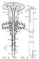
- Fig. 1 is a perspective view of a trocar having an obturator and a cannulaaccording to the present invention;
- Fig. 2 is a plan view in section of the trocar obturator with a penetrating tipin a covered position according to the present invention;
- Fig. 3 is a plan view in section of the obturator of Fig. 2 in a coupledrelationship with the cannula of Fig. 1 with the penetrating tip in an exposedposition;
- Fig. 4 is a perspective view, partially broken away, illustrating a protectoraccording to the present invention;
- Fig. 5 is an exploded perspective view of the obturator and the cannula ofFig. 1;
- Fig. 6 is a perspective view of a seal assembly employed in the cannula ofFig. 5;
- Fig. 7 is a side elevational view of the seal assembly shown in Fig. 6;
- Fig. 8 is a front elevational view of the seal assembly shown in Fig. 6;
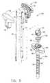
- Fig. 9 is a plan view in section of an alternative embodiment of a trocaraccording to the present invention; and
- Fig. 10 is an alternate embodiment of the protector of Fig. 3.
- As best shown in Fig. 1, the present invention is a low cost surgical trocar,generally designated 20, utilized as an assembly actuated trocar for endoscopicsurgical procedures to include all minimally invasive surgical procedures such aslaparoscopic and arthroscopic surgical procedures. The
surgical trocar 20 isdisposable and is intended to be used as a single patient use only device, meaningthat thetrocar 20 according to the present invention is to be used on only onepatient for a particular surgical procedure and then after such usage, thetrocar 20is to be discarded. - The
surgical trocar 20 is similar to the trocars found in EuropeanPatent Application Numbers 0 768 064; 0 768 063; 0 823 241 ;4,535,773;5,224,952; 5,256,149; 5,314,417; 5,387,197; 5,248,298; 5,330,437; 5,399,167;5,066,288; 5,215,526 and 5,267,965 and US Patent ApplicationSerial Number 08/572 172 (13/12/95). - The
surgical trocar 20 includes an obturator assembly, generally designated30, which is insertable through a cannula assembly, generally designated 80, forestablishing a surgical access port. Fig. 2 shows theobturator assembly 30comprising ahandle 32 having anopening 34 at a lower portion of thehandle 32.Thehandle 32 also includes a contact portion, generally designated 36, having apair of first retainingribs 37 and a pair of second retainingribs 39 positionedproximally to the pair of first retainingribs 37. Additionally, thecontact portion 36 also includes afirst ramp surface 41 and asecond ramp surface 43 positioned atan obtuse angle to thefirst ramp surface 41. - An
obturator shaft 45 having a first retained portion 47 and a secondretained portion 49 at a proximal end of theobturator shaft 45 are fixedly securedto thehandle 32 at the first retainingribs 37 and the second retainingribs 39respectively. The remainder of theobturator shaft 45 extends from thehandle 32through thehandle opening 34. - The
obturator shaft 45 also includes a penetrating tip, generally designated50, which is a blade assembly comprising aflat blade 55 for penetrating tissue anda pair ofupper shoulders 53. The penetratingtip 50 is fixed to the distal end oftheobturator shaft 45. - A
protector sleeve 57 having achannel 61 therethrough is slidably disposedaround theobturator shaft 45. Theprotector 57 also includes a flexibleproximalend 59 which is located, along with the proximal portion of theobturator shaft 45,within thehandle 32. As shown in Fig. 4, theprotector 57 is a single piece ofmolded plastic. The protectorproximal end 59 includes a pair ofdeflectable arms 62 that are resilient and flexible enough so that thedeflectable arms 62 can bedeflected outwardly from theobturator shaft 45, but yet resume their originalshape and size after deflection without breaking away from theprotector 57.However, it is not intended that theprotector 57 be limited merely to moldedplastic, but can also include any type of material that contains the required properties and characteristics for the flexibleproximal end 59 such as describedabove. - The protector
deflectable arms 62 include aninner surface 64 and anendsurface 68 at the end portion of eachdeflectable arm 62 as shown in Fig. 4. Theend surfaces 68 of the protectordeflectable arms 62 are initially located distallyfrom the first ramp surfaces 41 of thehandle contact portion 36 thus defining agap between the first ramp surfaces 41 and the deflectable arm end surfaces 68. - Similar to the
obturator shaft 45, theprotector 57 extends from thehandle 32 through thehandle opening 34. Theprotector 57 also includes a dilatingtipsection 67 located at the distal end of theprotector 57 for dilating tissue after thetrocar 20 is inserted into tissue for establishing a surgical access port. - The
protector 57 also includes aboss 66 circumferentially arranged aroundthe exterior of theprotector 57 and positioned near thehandle opening 34. Thedilatingtip section 67 of theprotector 57 includes anaperture 60 whichcommunicates with thechannel 61 of theprotector 57. Theaperture 60 is locatedat the distal end of theprotector 57 for permitting the penetratingtip 50 of theobturator shaft 45 to pass therethrough. - The
dilator tip 67 also includes aslot 69 which vertically extends from theaperture 60 to a point near the distal end of theprotector 57 for permitting thepenetratingtip 50 to pass therethrough (Fig. 4). Theprotector 57 also includes astop 65 circumferentially arranged within thechannel 61 at thedilator tip 67 forbeing supported by with theupper shoulders 53 of the penetratingtip 50. - Since, the flexible
proximal end 62 of theprotector 57 is located near thecontact portion 36 within thehandle 32, theprotector 57 is slideably movablearound theobturator shaft 45 between theupper shoulders 53 of the penetratingtip 50 of theobturator shaft 45 and thehandle contact portion 36. Thestop 65 is supported by theupper shoulders 53 of the penetratingtip 50 for preventing theprotector 57 from disengaging from theobturator handle 32. - As best illustrated in Fig. 2, the
obturator assembly 30 is in a protectedposition meaning that theprotector 57 is extended beyond the penetratingtip 50thereby covering the penetratingtip 50 and preventing any inadvertent cutting bytheflat blade 55. - Fig. 5 shows the
cannula assembly 80 comprising acannula sleeve 82defining a central passageway therethrough and aseal housing 85 located at theproximal end of thesleeve 82. Thesleeve 82 has ahelical thread 83 on anexterior surface of thesleeve 82 for positioning thesleeve 82 in tissue. Thehousing 85 also includes ahandle portion 84 which extends outwardly andsubstantially perpendicular from opposite sides of thehousing 85. Thehousing 85includes acentral opening 87 for receiving a seal assembly, generally designated100, therein. Theseal assembly 100 is disposed in thecentral opening 87 and isseated above thecannula sleeve 82. Thehousing 85 also includes aseal retainer 90 having tworetainer locks 92 and is seated against the upper surface of thesealassembly 100 and fixed to thecannula housing 85. Theseal retainer 90 is aconical plastic ring which permits theobturator assembly 30 to be inserted directlythrough theseal assembly 100. - The
housing 85 also includes a pair ofretainer lock slots 86 located onopposite sides of thehousing 85 for receiving the retainer locks 92 of thesealretainer 90. Accordingly, the retainer locks 92 of theretainer 90 are pressed fitinto theretainer lock slots 86 of thehousing 85 as best illustrated in Fig. 1. - As best illustrated in Fig. 3, the penetrating
tip 50 is exposed by retractingtheprotector 57 to a retracted position proximally within thecannula handle 32.Upon a proximal force F being asserted against theprotector 57, the deflectablearm end surfaces 68 contact the first ramp surfaces 41 of thehandle contactportion 36 and are slidably movable across the first ramp surfaces 41 of thehandlecontact portion 36. After initial contact of the end surfaces 68 with the first rampsurfaces 41, thedeflectable arms 62 are deflected outwardly away from theobturator shaft 45 as theprotector 57 is forced proximally within thehandle 32through the application of proximal force F since thedeflectable arms 62 are madeof a resilient, flexible material. Due the material properties of theproximal end 59, an opposing force is applied to theprotector 57 as thedeflectable arms 62 areslidably moved against thecontact portion 36. These material properties cause theprotector 57 to return distally to a protected position when the proximal force F isreleased from theprotector 57. - Once the deflectable arm end surfaces 68 are slid past the first rampsurfaces 41, the
inner surfaces 64 of thedeflectable arms 62 contact the secondramp surfaces 43 of thehandle contact portion 36 and are slidably movable acrossthe second ramp surfaces 43. Accordingly, the end surfaces 68 and theinnersurfaces 64 of thedeflectable arm 62 are slideably movable against the first rampsurfaces 41 and the second ramp surfaces 43 of thehandle contact portion 36respectively to facilitate a smooth retraction of theprotector 57 within theobturator handle 32. The first ramp surfaces 41 are arranged substantiallyperpendicular to theobturator shaft 45 in order to provide a sufficient resistivesurface for thedeflectable arms 62 to prevent thedeflectable arms 62 from easilysliding past the first ramp surfaces 41. This arrangement ensures that theprotector 57 is not inadvertently withdrawn into the obturator handle 32 until intended. Because the second ramp surfaces 43 are at an obtuse angle with respect to the firstramp surfaces 41, there is a less resistive surface for thedeflectable arms 62. Thisallows theprotector 57 to be easily retracted at this point in the retraction. - The protector is retracted to its retracted position through the application ofthe proximal force F which can be applied to the
protector 57 manually, forinstance, by the surgeon grasping theprotector boss 66 and withdrawing theprotector 57 proximally toward thehandle 32. Alternatively, theprotector 57 isretracted to its retracted position upon insertion of theobturator assembly 30through thecannula assembly 80 and into thecannula sleeve 82 until thedilator tip 67 of theprotector 57 extends through the distal end of thecannula sleeve 82 asshown in Figs. 1 and 3 and up until the point where theprotector boss 66 contactsthehandle 32 at thehandle opening 34. At this point, theboss 66 of theprotector 57 will contact the inner surface of the conically-shapedretainer 90 therebycausing the proximal force F to be asserted against theprotector 57. The proximalforce F advances theprotector 57 proximally within thehandle 32 for extendingthe penetratingtip 50 through theprotector aperture 60 thereby exposing theflatblade 55 for cutting tissue. Thehandle opening 34 has a smaller diameter than theouter diameter of the circumferentially arrangedprotector boss 66 such that theprotector boss 66 cannot be inserted within theobturator handle 32. - Additionally, as shown in Fig. 5, the obturator handle 32 also includesretaining
pins 33 laterally extending from the handle adjacent thehandle opening 34. Thus, theobturator assembly 30 can be locked to thecannula assembly 80 byrotating the retaining pins 33 into thepin slots 94 of theseal retainer 90 through aslight rotation motion of thehandle 32 once theobturator assembly 30 has beeninserted through thecannula assembly 80 thereby forming the assembly actuatedtrocar 20. - The
handle 32 is unlocked merely through reversing the rotation actionsuch that therotating pins 33 disengage from thepin slots 94 which will cause theprotector 57 to return to its protected position covering the penetratingtip 50. The resilient, flexible properties of the protectorproximal end 59 will cause theprotector 57 to advance distally over the penetratingtip 50 upon the decoupling ofthehandle 32 from thecannula housing 85. - As shown in Figs. 6-8, the
seal assembly 100 includes ahousing seal 104which is a circumferential elastomeric member that surrounds adiaphragm seal 108. The diaphragm seal has acentral aperture 110 therethrough and has asubstantially convex shape which extends upwardly and outwardly from thehousing seal 104. Aflange 112 surrounds the outer periphery of thehousing seal 104. - Additionally, the
seal assembly 100 includes an S-shapedpressure seal 120comprising twosidewalls 122 extending distally from the under side of thehousingseal 104 and thediaphragm seal 108. As shown in Fig. 8, eachsidewall 122 hasanend section 126 that is adjacent to each other and define an S-shapedslit 128therebetween. Accordingly, thecentral aperture 110 and the S-shapedslit 128 oftheseal assembly 100 permit theobturator assembly 30 to be inserted therethroughin sealing engagement thereby preventing the loss of operating fluid. However,once thecannula assembly 80 has been placed, theobturator assembly 30 can bewithdrawn from thecannula assembly 80 for the insertion of additional surgicalinstruments through thecannula assembly 80 for facilitating the surgicalprocedure. Similar toobturator assembly 30, additional surgical instrumentsinserted through theseal assembly 100 are sealed by theseal assembly 100,particularly by the S-shaped pressure seal and thediaphragm seal 108. - A second embodiment of a
protector 57a according to the present inventionis illustrated in Fig. 10 wherein theprotector 57a includes a flexibleproximal end 59a which is asinusoidal member 72 having acentral bore 73 and a pair ofproximal tips 74 having anotch 76 interposed between eachtip 74. Thenotch 76and thecentral bore 73 are aligned directly with thechannel 61 of theprotector 57a. Both thenotch 76, thecentral bore 73, along with thechannel 61 of theprotector 57a are shaped to receive theobturator shaft 45 due to their direct alignment with each other. Theproximal tips 74 are positioned near the first rampsurfaces 41 of thehandle engagement portion 36 for contacting the first rampsurfaces 41 upon proximal force F being asserted against theprotector 57a in themanner described above. Thetips 74 are relatively flat members that will contactthe first ramp surfaces 41 without advancing to the second ramp surfaces 43. - Similar to the protector 57 (Fig. 4) described above, the
protector 57a isalso made of molded plastic as single, integral component. Thesinusoidalmember 72 through both its configuration and material composition is a resilient,flexible member which permits theprotector 57a to function similar to theprotector 57 (Fig. 4) described above. - Another embodiment according to the present invention is illustrated inFig. 9 wherein the
trocar 20 includes aprotector 57b having aproximal end 70.Thecontact portion 36 of the cannula handle 32 comprises a pair ofdeflectablemembers 48 that are movable by theproximal end 70 of theprotector 57b. Thedeflectable members 48 are made of a flexible and resilient material such that oncethe proximal force F is asserted against theprotector 57b, theproximal end 70 oftheprotector 57b is advanced proximally into thecontact portion 36 slidablymoving against the inner surfaces of thedeflectable members 48. The protectorproximal end 70 outwardly deflects thedeflectable members 48 away from theobturator shaft 45 thereby retracting theprotector 57b and exposing the penetratingtip 50. Accordingly, this alternative arrangement provides similar advantages tothe preferred embodiment shown in Figs. 2-5. - As mentioned above, the
trocar 20 according to the present inventionprovides several advantages. In particular, thetrocar 20 is an assembly actuatedtrocar and is directed to being the trocar of choice in the current cost conscioussurgical environment. Since cost is a major issue with the present surgicalcommunity, it is often necessary to develop novel and creative instruments andtechniques in order to provide safe, efficacious and quality surgical treatment forthe patient, while at the same time seeking to reduce cost from the surgicalprocedure. One creative way of reducing cost from a surgical procedure affordedby the present invention, is to utilize a single fully returnable safety shielded trocarsuch as those described as part of the field and background of the invention, alongwith one or more of thetrocars 20 according to the present invention. - Since a fully returnable shield trocar is more costly than the
trocar 20according to the present invention, mainly due to the cost of additional parts andmanufacturing, many surgeons will seek to limit the number of fully returnablesafety shielded trocars utilized during a single surgical procedure. Thus, manysurgeons may opt to utilize only one fully returnable safety shielded trocar in orderto establish a primary access port in the patient. The primary access port beingestablished once the safety shielded obturator is removed from the cannula and anendoscope is inserted in its place in order to establish visualization for theplacement for secondary access ports. - The secondary access ports are utilized to accommodate various types ofsurgical instrumentation in order to facilitate the surgical procedure. Accordingly,the
trocar 20 according to the present invention can be utilized to establish thesesecondary access ports. As illustrated in Fig. 2, since thetrocar 20 according tothe present invention utilizes aprotector 57, the penetratingtip 55 will be covered,and accordingly, a degree of safety is provided to all those who handle theobturator assembly 30 prior to the engagement and locking of theobturatorassembly 30 into thecannula assembly 80. Additionally, theseal assembly 100 ofthetrocar 20 also will be protected since the penetratingtip 55 remains covered asthe obturator is slid through theseal assembly 100 into thecannula sleeve 82. - Although this invention has been described in connection with its mostpreferred embodiments, it will become readily apparent to those reviewing thisdetailed specification that numerous additional embodiments fall well within thescope of the claimed invention as set forth in the claims which appearbelow.
Claims (10)
- A surgical trocar (20) comprising a cannula assembly (80) including a sleevehaving a proximal end and a distal end and a passageway therethrough anda housing (85) having an opening and being located at said proximal end of saidsleeve, said housing opening being aligned with said passageway of saidsleeve, an obturator assembly (30) insertable into said cannula assembly andincluding a handle (32), an obturator shaft (45) connected to said handle and a distalend opposite said proximal end, a penetrating tip (50) located at said distal endof said obturator shaft (45), and a protector (57) having a distal end and slidablydisposed around said obturator shaft (45) for covering said penetrating tip (50) ofsaid obturator shaft (45) in a protected position, said protector (57) having an aperture at said distal end forpermitting said penetrating tip (50) of said obturator shaft (45) to pass therethrough; saidprotector (57) also having a flexible proximal end (59,59a) movable against said handleto a retracted position from said protected position in order to expose said penetrating tip (50) past saidprotector aperture and said sleeve distal end when said handle contacts saidhousing upon an insertion of said obturator assembly into said cannulaassembly.
- The surgical trocar (20) of Claim 1, wherein said flexible proximal end (59) ofsaid protector (57) includes at least one deflectable arm (62) slidably movableagainst a contact portion (36) of said handle (32).
- The surgical trocar (20) of Claim 2, wherein said flexible proximal end (59) ofsaid protector includes a pair of deflectable arms (62) slidably movable againstsaid contact portion (36) of said handle (32).
- The surgical trocar (20) of Claim 3, wherein said contact portion (36) includesa first ramp surface (41) and each deflectable arm (62) includes an end surface at a proximal end of each arm (62) for slidably moving against said first rampsurface (41) of said contact portion (36).
- The surgical trocar (20) of Claim 4, wherein said contact portion (36) furtherincludes a second ramp surface (43) adjacent said first ramp surface (41) and eachdeflectable arm (62) includes an inner surface (64) adjacent said end surface forslidably moving said second ramp surface (43).
- The surgical trocar (20) of Claim 5, wherein said protector (57) includes aboss (66) for contacting said handle (32) when said protector (57) is retracted to saidretracted position.
- The surgical trocar (20) of Claim 6, including a seal assembly (100) located insaid opening (87) of said housing (85).
- The surgical trocar (20) of Claim 7, wherein said housing (85) includes at leastone slot (94) and said handle (32) includes at least one pin (33) detachably engagablewith said at least one slot (86) for locking said handle (32) to said housing (85).
- An obturator assembly (30) comprising:a handle (32) having an opening (34) therein and a contact portion (36);an obturator shaft (45) extending through said handle opening (34) and havinga proximal end fixed to said handle (32) and a distal end having a penetrating tip (50)thereon; anda protector (57) slidably disposed around said obturator shaft (45) and alsoextending through said handle opening (34) for covering said penetrating tip (50) ofsaid obturator shaft (45) in a protected position, said protector (57) having an aperture at a distal end thereoffor permitting said penetrating tip (50) of said obturator shaft (45) to pass therethrough, said protector (57) also having a flexible proximal end (59) movableagainst said contact portion (36) of said handle for moving said protector (57) to a retracted position from said protected position in order toexpose said penetrating tip (50), when a proximal force is placed against saidprotector (57).
- An obturator assembly (30) comprising:a handle (32) having an opening (34) therein and a flexible contact portion (36);an obturator shaft (45) extending through said handle opening (34) and havinga proximal end fixed to said handle (32) and a distal end having a penetrating tip (50)thereon;a protector (57) slidably disposed around said obturator shaft (45) and alsoextending through said handle opening (34) for covering said penetrating tip (50) ofsaid obturator shaft (45) in a protected position, said protector (57) having an aperture at a distal end thereoffor permitting said penetrating tip (50) of said obturator shaft (45) to passtherethrough, said protector (57) also having a proximal end movable againstsaid flexible contact portion (36) of said handle (32) for moving said protector (57) to a retracted position from said protected position in orderto expose said penetrating tip (50) when a proximal force is placed against saidprotector.
Applications Claiming Priority (2)
| Application Number | Priority Date | Filing Date | Title |
|---|---|---|---|
| US08/827,317US5879332A (en) | 1997-03-26 | 1997-03-26 | Trocar having protector with flexible end |
| US827317 | 1997-03-26 |
Publications (3)
| Publication Number | Publication Date |
|---|---|
| EP0867150A2 EP0867150A2 (en) | 1998-09-30 |
| EP0867150A3 EP0867150A3 (en) | 2000-02-23 |
| EP0867150B1true EP0867150B1 (en) | 2004-11-24 |
Family
ID=25248907
Family Applications (1)
| Application Number | Title | Priority Date | Filing Date |
|---|---|---|---|
| EP98302237AExpired - LifetimeEP0867150B1 (en) | 1997-03-26 | 1998-03-25 | Trocar having protector with flexible end |
Country Status (7)
| Country | Link |
|---|---|
| US (3) | US5879332A (en) |
| EP (1) | EP0867150B1 (en) |
| JP (1) | JP3930142B2 (en) |
| AU (1) | AU749818B2 (en) |
| CA (1) | CA2233029C (en) |
| DE (1) | DE69827689T2 (en) |
| ES (1) | ES2231942T3 (en) |
Cited By (2)
| Publication number | Priority date | Publication date | Assignee | Title |
|---|---|---|---|---|
| US8137318B2 (en) | 2008-07-09 | 2012-03-20 | Aesculap Ag | Surgical protection device for a surgical sealing element and surgical sealing system |
| US8246586B2 (en) | 2008-07-09 | 2012-08-21 | Aesculap Ag | Surgical sealing element holder for holding a surgical sealing element and surgical sealing system |
Families Citing this family (134)
| Publication number | Priority date | Publication date | Assignee | Title |
|---|---|---|---|---|
| US6443973B1 (en) | 1999-06-02 | 2002-09-03 | Power Medical Interventions, Inc. | Electromechanical driver device for use with anastomosing, stapling, and resecting instruments |
| US6491201B1 (en) | 2000-02-22 | 2002-12-10 | Power Medical Interventions, Inc. | Fluid delivery mechanism for use with anastomosing, stapling, and resecting instruments |
| US6793652B1 (en) | 1999-06-02 | 2004-09-21 | Power Medical Interventions, Inc. | Electro-mechanical surgical device |
| US7695485B2 (en) | 2001-11-30 | 2010-04-13 | Power Medical Interventions, Llc | Surgical device |
| US7951071B2 (en) | 1999-06-02 | 2011-05-31 | Tyco Healthcare Group Lp | Moisture-detecting shaft for use with an electro-mechanical surgical device |
| US7032798B2 (en) | 1999-06-02 | 2006-04-25 | Power Medical Interventions, Inc. | Electro-mechanical surgical device |
| US6315184B1 (en) | 1999-06-02 | 2001-11-13 | Powermed, Inc. | Stapling device for use with an electromechanical driver device for use with anastomosing, stapling, and resecting instruments |
| US6981941B2 (en) | 1999-06-02 | 2006-01-03 | Power Medical Interventions | Electro-mechanical surgical device |
| US8025199B2 (en) | 2004-02-23 | 2011-09-27 | Tyco Healthcare Group Lp | Surgical cutting and stapling device |
| MXPA01013402A (en) | 1999-06-22 | 2004-03-10 | E Blanco Ernesto | Safety trocar with progressive cutting tip guards and gas jet tissue deflector. |
| US20060015075A1 (en)* | 1999-06-22 | 2006-01-19 | Erblan Surgical Inc. | Guarded infusor needle and infusor locking system |
| US6488197B1 (en) | 2000-02-22 | 2002-12-03 | Power Medical Interventions, Inc. | Fluid delivery device for use with anastomosing resecting and stapling instruments |
| US8016855B2 (en) | 2002-01-08 | 2011-09-13 | Tyco Healthcare Group Lp | Surgical device |
| US20020161387A1 (en)* | 2000-06-22 | 2002-10-31 | Blanco Ernesto E. | Safety trocar with progressive cutting tip guards and gas jet tissue deflector |
| US9192410B2 (en) | 2001-03-14 | 2015-11-24 | Covidien Lp | Trocar device |
| US7905897B2 (en)* | 2001-03-14 | 2011-03-15 | Tyco Healthcare Group Lp | Trocar device |
| USD559387S1 (en) | 2001-08-31 | 2008-01-08 | Conmed Corporation | Cannula tube |
| US6989003B2 (en)* | 2001-08-31 | 2006-01-24 | Conmed Corporation | Obturator and cannula for a trocar adapted for ease of insertion and removal |
| USD495054S1 (en) | 2001-08-31 | 2004-08-24 | Conmed Corporation | Cannula head |
| USD495053S1 (en) | 2001-08-31 | 2004-08-24 | Conmed Corporation | Trocar |
| US7344519B2 (en)* | 2001-08-31 | 2008-03-18 | Conmed Corporation | Trocar system |
| US9113878B2 (en) | 2002-01-08 | 2015-08-25 | Covidien Lp | Pinion clip for right angle linear cutter |
| US7306574B2 (en)* | 2002-01-17 | 2007-12-11 | Optivia Medical, Llc | Steerable dilatation system, dilator, and related methods for stepped dilatation |
| USD518177S1 (en) | 2002-03-08 | 2006-03-28 | Erblan Surgical, Inc. | Safety trocar with progressive cutting tip guards and gas jet tissue deflector |
| CA2489727C (en) | 2002-06-14 | 2011-04-26 | Power Medical Interventions, Inc. | Surgical device |
| US6793678B2 (en) | 2002-06-27 | 2004-09-21 | Depuy Acromed, Inc. | Prosthetic intervertebral motion disc having dampening |
| US7401072B2 (en) | 2003-06-10 | 2008-07-15 | Google Inc. | Named URL entry |
| USD499484S1 (en) | 2003-08-12 | 2004-12-07 | Erblan Surgical, Inc. | Trocar seal-valve |
| USD517694S1 (en) | 2003-08-12 | 2006-03-21 | Erblan Surgical, Inc | Tip portion of an infusor |
| US7226434B2 (en) | 2003-10-31 | 2007-06-05 | Tyco Healthcare Group Lp | Safety shield |
| US7988664B2 (en) | 2004-11-01 | 2011-08-02 | Tyco Healthcare Group Lp | Locking clip with trigger bushing |
| US8475476B2 (en)* | 2004-06-01 | 2013-07-02 | Cook Medical Technologies Llc | System and method for accessing a body cavity |
| US9387313B2 (en) | 2004-08-03 | 2016-07-12 | Interventional Spine, Inc. | Telescopic percutaneous tissue dilation systems and related methods |
| US7905857B2 (en) | 2005-07-11 | 2011-03-15 | Covidien Ag | Needle assembly including obturator with safety reset |
| US7850650B2 (en) | 2005-07-11 | 2010-12-14 | Covidien Ag | Needle safety shield with reset |
| US7828773B2 (en) | 2005-07-11 | 2010-11-09 | Covidien Ag | Safety reset key and needle assembly |
| USD561338S1 (en) | 2004-12-06 | 2008-02-05 | Erblan Surgical, Inc. | Trocar and trocar actuation mechanism |
| US20060276747A1 (en) | 2005-06-06 | 2006-12-07 | Sherwood Services Ag | Needle assembly with removable depth stop |
| US7988670B2 (en)* | 2005-06-30 | 2011-08-02 | Tyco Healthcare Group Lp | Trocar assembly with rotatable obturator housing |
| EP1907042B1 (en) | 2005-07-06 | 2009-03-11 | Vascular Pathways Inc. | Intravenous catheter insertion device and method of use |
| US7731692B2 (en) | 2005-07-11 | 2010-06-08 | Covidien Ag | Device for shielding a sharp tip of a cannula and method of using the same |
| US20070010823A1 (en)* | 2005-07-11 | 2007-01-11 | Cannuflow, Inc. | Arthroscopic shaver system |
| US7654735B2 (en) | 2005-11-03 | 2010-02-02 | Covidien Ag | Electronic thermometer |
| DE102006015690A1 (en)* | 2006-03-27 | 2007-10-11 | Aesculap Ag & Co. Kg | Surgical sealing element, surgical seal and surgical sealing system |
| US8657843B2 (en) | 2006-05-03 | 2014-02-25 | Applied Medical Resources Corporation | Shield lockout for bladed obturator and trocars |
| US8801741B2 (en)* | 2006-05-03 | 2014-08-12 | Applied Medical Resources Corporation | Flat blade shielded obturator |
| US9079762B2 (en) | 2006-09-22 | 2015-07-14 | Ethicon Endo-Surgery, Inc. | Micro-electromechanical device |
| US7561317B2 (en) | 2006-11-03 | 2009-07-14 | Ethicon Endo-Surgery, Inc. | Resonant Fourier scanning |
| WO2008070863A2 (en) | 2006-12-07 | 2008-06-12 | Interventional Spine, Inc. | Intervertebral implant |
| AU2007334420B2 (en)* | 2006-12-15 | 2013-03-14 | Covidien Lp | Trocar assembly with obturator design |
| US20100016878A1 (en)* | 2006-12-15 | 2010-01-21 | Tyco Healthcare Group Lp | Trocar assembly with obturator and retractable stylet |
| US7713265B2 (en) | 2006-12-22 | 2010-05-11 | Ethicon Endo-Surgery, Inc. | Apparatus and method for medically treating a tattoo |
| US8801606B2 (en) | 2007-01-09 | 2014-08-12 | Ethicon Endo-Surgery, Inc. | Method of in vivo monitoring using an imaging system including scanned beam imaging unit |
| US8273015B2 (en) | 2007-01-09 | 2012-09-25 | Ethicon Endo-Surgery, Inc. | Methods for imaging the anatomy with an anatomically secured scanner assembly |
| US7589316B2 (en) | 2007-01-18 | 2009-09-15 | Ethicon Endo-Surgery, Inc. | Scanning beam imaging with adjustable detector sensitivity or gain |
| US8216214B2 (en) | 2007-03-12 | 2012-07-10 | Ethicon Endo-Surgery, Inc. | Power modulation of a scanning beam for imaging, therapy, and/or diagnosis |
| US8626271B2 (en) | 2007-04-13 | 2014-01-07 | Ethicon Endo-Surgery, Inc. | System and method using fluorescence to examine within a patient's anatomy |
| US7995045B2 (en) | 2007-04-13 | 2011-08-09 | Ethicon Endo-Surgery, Inc. | Combined SBI and conventional image processor |
| AU2008243046B2 (en)* | 2007-04-18 | 2013-06-06 | Covidien Lp | Trocar assembly with obturator dissector |
| EP2150304B1 (en) | 2007-05-07 | 2010-12-01 | Vascular Pathways Inc. | Intravenous catheter insertion and blood sample devices and method of use |
| US8160678B2 (en) | 2007-06-18 | 2012-04-17 | Ethicon Endo-Surgery, Inc. | Methods and devices for repairing damaged or diseased tissue using a scanning beam assembly |
| US20080319467A1 (en)* | 2007-06-22 | 2008-12-25 | Thomas Wenchell | Thin bladed obturator |
| US8900307B2 (en) | 2007-06-26 | 2014-12-02 | DePuy Synthes Products, LLC | Highly lordosed fusion cage |
| US7982776B2 (en) | 2007-07-13 | 2011-07-19 | Ethicon Endo-Surgery, Inc. | SBI motion artifact removal apparatus and method |
| US9125552B2 (en) | 2007-07-31 | 2015-09-08 | Ethicon Endo-Surgery, Inc. | Optical scanning module and means for attaching the module to medical instruments for introducing the module into the anatomy |
| US7983739B2 (en) | 2007-08-27 | 2011-07-19 | Ethicon Endo-Surgery, Inc. | Position tracking and control for a scanning assembly |
| US7925333B2 (en) | 2007-08-28 | 2011-04-12 | Ethicon Endo-Surgery, Inc. | Medical device including scanned beam unit with operational control features |
| AU2008302043B2 (en) | 2007-09-21 | 2013-06-27 | Covidien Lp | Surgical device |
| CN102793571B (en) | 2007-09-21 | 2014-12-17 | 柯惠Lp公司 | Surgical device |
| WO2009042874A1 (en) | 2007-09-27 | 2009-04-02 | Tyco Healthcare Group Lp | I.v. catheter assembly and needle safety device |
| US8282663B2 (en) | 2007-10-05 | 2012-10-09 | Tyco Healthcare Group Lp | Bladeless obturator for use in a surgical trocar assembly |
| US8357104B2 (en) | 2007-11-01 | 2013-01-22 | Coviden Lp | Active stylet safety shield |
| DE602008002806D1 (en) | 2007-12-20 | 2010-11-11 | Tyco Healthcare | Locking cap arrangement with spring-loaded collar |
| EP2237748B1 (en) | 2008-01-17 | 2012-09-05 | Synthes GmbH | An expandable intervertebral implant |
| US7989928B2 (en)* | 2008-02-05 | 2011-08-02 | Advanced Semiconductor Engineering Inc. | Semiconductor device packages with electromagnetic interference shielding |
| US8050520B2 (en) | 2008-03-27 | 2011-11-01 | Ethicon Endo-Surgery, Inc. | Method for creating a pixel image from sampled data of a scanned beam imager |
| US8936641B2 (en) | 2008-04-05 | 2015-01-20 | DePuy Synthes Products, LLC | Expandable intervertebral implant |
| US8332014B2 (en) | 2008-04-25 | 2012-12-11 | Ethicon Endo-Surgery, Inc. | Scanned beam device and method using same which measures the reflectance of patient tissue |
| US20090270819A1 (en)* | 2008-04-29 | 2009-10-29 | Dario Vitali | Optical safety trocar and method of use thereof |
| US8740925B2 (en)* | 2008-10-10 | 2014-06-03 | Covidien Lp | Trocar assembly |
| BRPI0917035A2 (en) | 2008-12-04 | 2019-09-24 | Pivot Medical Inc | "telescope access cannula, telescope shutter, system, method for providing an access corridor from a first off-site location to a second on-site location" |
| US9526620B2 (en) | 2009-03-30 | 2016-12-27 | DePuy Synthes Products, Inc. | Zero profile spinal fusion cage |
| ITRM20090257A1 (en) | 2009-05-19 | 2010-11-20 | Ab Medica Spa | TROCAR. |
| US20110028795A1 (en)* | 2009-07-29 | 2011-02-03 | Tyco Healthcare Group Lp | Surgical portal device including textured surface |
| US9393129B2 (en) | 2009-12-10 | 2016-07-19 | DePuy Synthes Products, Inc. | Bellows-like expandable interbody fusion cage |
| US8979883B2 (en) | 2009-12-17 | 2015-03-17 | Covidien Lp | Obturator tip |
| US9226774B2 (en) | 2009-12-17 | 2016-01-05 | Covidien Lp | Visual obturator with tip openings |
| US9872971B2 (en) | 2010-05-14 | 2018-01-23 | C. R. Bard, Inc. | Guidewire extension system for a catheter placement device |
| US9950139B2 (en) | 2010-05-14 | 2018-04-24 | C. R. Bard, Inc. | Catheter placement device including guidewire and catheter control elements |
| US10384039B2 (en) | 2010-05-14 | 2019-08-20 | C. R. Bard, Inc. | Catheter insertion device including top-mounted advancement components |
| US8932258B2 (en) | 2010-05-14 | 2015-01-13 | C. R. Bard, Inc. | Catheter placement device and method |
| US11925779B2 (en) | 2010-05-14 | 2024-03-12 | C. R. Bard, Inc. | Catheter insertion device including top-mounted advancement components |
| US8979860B2 (en) | 2010-06-24 | 2015-03-17 | DePuy Synthes Products. LLC | Enhanced cage insertion device |
| US9907560B2 (en) | 2010-06-24 | 2018-03-06 | DePuy Synthes Products, Inc. | Flexible vertebral body shavers |
| US8623091B2 (en) | 2010-06-29 | 2014-01-07 | DePuy Synthes Products, LLC | Distractible intervertebral implant |
| US8961552B2 (en) | 2010-09-21 | 2015-02-24 | Covidien Lp | Bladeless obturators and bladeless obturator members |
| US9402732B2 (en) | 2010-10-11 | 2016-08-02 | DePuy Synthes Products, Inc. | Expandable interspinous process spacer implant |
| US8690833B2 (en) | 2011-01-31 | 2014-04-08 | Vascular Pathways, Inc. | Intravenous catheter and insertion device with reduced blood spatter |
| ES2835652T3 (en) | 2011-02-25 | 2021-06-22 | Bard Inc C R | Medical component insertion device including a retractable needle |
| USD653329S1 (en)* | 2011-05-11 | 2012-01-31 | Femasys Inc. | Device for relieving fluid pressure |
| USD903101S1 (en) | 2011-05-13 | 2020-11-24 | C. R. Bard, Inc. | Catheter |
| EP2877127B1 (en) | 2012-07-26 | 2019-08-21 | Synthes GmbH | Expandable implant |
| US20140067069A1 (en) | 2012-08-30 | 2014-03-06 | Interventional Spine, Inc. | Artificial disc |
| WO2014120741A1 (en) | 2013-01-30 | 2014-08-07 | Vascular Pathways, Inc. | Systems and methods for venipuncture and catheter placement |
| US9717601B2 (en) | 2013-02-28 | 2017-08-01 | DePuy Synthes Products, Inc. | Expandable intervertebral implant, system, kit and method |
| US9522070B2 (en) | 2013-03-07 | 2016-12-20 | Interventional Spine, Inc. | Intervertebral implant |
| FR3007636B1 (en)* | 2013-07-01 | 2016-09-02 | Laurent Fumex | TROCART PERFORANT. |
| WO2016037127A1 (en) | 2014-09-05 | 2016-03-10 | C.R. Bard, Inc. | Catheter insertion device including retractable needle |
| US11426290B2 (en) | 2015-03-06 | 2022-08-30 | DePuy Synthes Products, Inc. | Expandable intervertebral implant, system, kit and method |
| USD903100S1 (en) | 2015-05-01 | 2020-11-24 | C. R. Bard, Inc. | Catheter placement device |
| CN113350614A (en) | 2015-05-15 | 2021-09-07 | C·R·巴德股份有限公司 | Catheter placement device including extendable needle safety feature |
| US9913727B2 (en) | 2015-07-02 | 2018-03-13 | Medos International Sarl | Expandable implant |
| US10588658B2 (en)* | 2015-07-25 | 2020-03-17 | Aok Innovations, Llc | Device and method for access to interior body regions |
| EP3474784A2 (en) | 2016-06-28 | 2019-05-01 | Eit Emerging Implant Technologies GmbH | Expandable and angularly adjustable intervertebral cages with articulating joint |
| US11510788B2 (en) | 2016-06-28 | 2022-11-29 | Eit Emerging Implant Technologies Gmbh | Expandable, angularly adjustable intervertebral cages |
| US10493262B2 (en) | 2016-09-12 | 2019-12-03 | C. R. Bard, Inc. | Blood control for a catheter insertion device |
| US10537436B2 (en) | 2016-11-01 | 2020-01-21 | DePuy Synthes Products, Inc. | Curved expandable cage |
| CN106618688A (en)* | 2016-12-09 | 2017-05-10 | 成都五义医疗科技有限公司 | Puncture needle containing harmless protector |
| US10888433B2 (en) | 2016-12-14 | 2021-01-12 | DePuy Synthes Products, Inc. | Intervertebral implant inserter and related methods |
| EP3585471B1 (en) | 2017-03-01 | 2025-01-01 | C. R. Bard, Inc. | Catheter insertion device |
| US10398563B2 (en) | 2017-05-08 | 2019-09-03 | Medos International Sarl | Expandable cage |
| US11344424B2 (en) | 2017-06-14 | 2022-05-31 | Medos International Sarl | Expandable intervertebral implant and related methods |
| US10940016B2 (en) | 2017-07-05 | 2021-03-09 | Medos International Sarl | Expandable intervertebral fusion cage |
| ES2980192T3 (en) | 2018-03-07 | 2024-09-30 | Bard Access Systems Inc | Guidewire advancement and blood reflux systems for a medical device insertion system |
| USD921884S1 (en) | 2018-07-27 | 2021-06-08 | Bard Access Systems, Inc. | Catheter insertion device |
| US11446156B2 (en) | 2018-10-25 | 2022-09-20 | Medos International Sarl | Expandable intervertebral implant, inserter instrument, and related methods |
| CA3151126A1 (en) | 2019-08-19 | 2021-02-25 | Becton, Dickinson And Company | Midline catheter placement device |
| US11426286B2 (en) | 2020-03-06 | 2022-08-30 | Eit Emerging Implant Technologies Gmbh | Expandable intervertebral implant |
| US11850160B2 (en) | 2021-03-26 | 2023-12-26 | Medos International Sarl | Expandable lordotic intervertebral fusion cage |
| US11752009B2 (en) | 2021-04-06 | 2023-09-12 | Medos International Sarl | Expandable intervertebral fusion cage |
| US11963692B2 (en) | 2021-04-30 | 2024-04-23 | Aok Innovations, Llc | Body cavity access device |
| US12090064B2 (en) | 2022-03-01 | 2024-09-17 | Medos International Sarl | Stabilization members for expandable intervertebral implants, and related systems and methods |
| US12207843B2 (en) | 2023-06-09 | 2025-01-28 | Reza Mohajer-Shojaee | Resistance-free trocar assembly |
| KR102822010B1 (en)* | 2024-07-11 | 2025-06-19 | 에스앤씨 주식회사 | Thoracic trocar assembly |
Family Cites Families (20)
| Publication number | Priority date | Publication date | Assignee | Title |
|---|---|---|---|---|
| US4535773A (en)* | 1982-03-26 | 1985-08-20 | Inbae Yoon | Safety puncturing instrument and method |
| US5030206A (en)* | 1986-10-17 | 1991-07-09 | United States Surgical Corporation | Trocar |
| US4840613A (en)* | 1988-04-27 | 1989-06-20 | Menlo Care, Inc. | Protective sheath for catheter assembly |
| GB8816033D0 (en)* | 1988-07-06 | 1988-08-10 | Ethicon Inc | Improved safety trocar |
| US5224952A (en)* | 1988-07-06 | 1993-07-06 | Ethicon, Inc. | Safety trocar |
| US5267965A (en)* | 1988-07-06 | 1993-12-07 | Ethicon, Inc. | Safety trocar |
| US5215526A (en)* | 1988-07-06 | 1993-06-01 | Ethicon, Inc. | Safety trocar |
| US5330497A (en)* | 1989-11-22 | 1994-07-19 | Dexide, Inc. | Locking trocar sleeve |
| US5152754A (en)* | 1991-02-15 | 1992-10-06 | Minnesota Mining And Manufacturing Company | Trocar |
| US5312354A (en)* | 1991-11-04 | 1994-05-17 | American Cyanamid Company | Safety trocar instrument having a retractable point actuated by a trigger sleeve |
| US5256149A (en)* | 1992-02-14 | 1993-10-26 | Ethicon, Inc. | Trocar having transparent cannula and method of using |
| US5248298A (en)* | 1992-04-16 | 1993-09-28 | Ethicon, Inc. | Insert for shielded trocar |
| US5314417A (en)* | 1992-12-22 | 1994-05-24 | Ethicon, Inc. | Safety trocar |
| US5387197A (en)* | 1993-02-25 | 1995-02-07 | Ethicon, Inc. | Trocar safety shield locking mechanism |
| US5383860A (en)* | 1993-03-02 | 1995-01-24 | M.I.S. Technology International, Inc. | Two-part conductive cannula with adaptive disposable non-invasive element |
| US5364372A (en)* | 1993-03-29 | 1994-11-15 | Endoscopic Concepts, Inc. | Trocar and cannula |
| US5346459A (en)* | 1993-04-14 | 1994-09-13 | Minnesota Mining And Manufacturing Company | Trocar |
| US5554167A (en)* | 1993-10-08 | 1996-09-10 | United States Surgical Corporation | Tissue piercing members |
| US5330437A (en)* | 1993-11-12 | 1994-07-19 | Ethicon Endo-Surgery | Self sealing flexible elastomeric valve and trocar assembly for incorporating same |
| US5545150A (en)* | 1994-05-06 | 1996-08-13 | Endoscopic Concepts, Inc. | Trocar |
- 1997
- 1997-03-26USUS08/827,317patent/US5879332A/ennot_activeExpired - Lifetime
- 1998
- 1998-03-18AUAU59371/98Apatent/AU749818B2/ennot_activeExpired
- 1998-03-24CACA002233029Apatent/CA2233029C/ennot_activeExpired - Lifetime
- 1998-03-25EPEP98302237Apatent/EP0867150B1/ennot_activeExpired - Lifetime
- 1998-03-25JPJP09522098Apatent/JP3930142B2/ennot_activeExpired - Lifetime
- 1998-03-25ESES98302237Tpatent/ES2231942T3/ennot_activeExpired - Lifetime
- 1998-03-25DEDE69827689Tpatent/DE69827689T2/ennot_activeExpired - Lifetime
- 1998-04-09USUS09/057,687patent/US5997510A/ennot_activeExpired - Lifetime
- 1999
- 1999-01-06USUS09/226,430patent/US5947930A/ennot_activeExpired - Lifetime
Cited By (3)
| Publication number | Priority date | Publication date | Assignee | Title |
|---|---|---|---|---|
| US8137318B2 (en) | 2008-07-09 | 2012-03-20 | Aesculap Ag | Surgical protection device for a surgical sealing element and surgical sealing system |
| US8246586B2 (en) | 2008-07-09 | 2012-08-21 | Aesculap Ag | Surgical sealing element holder for holding a surgical sealing element and surgical sealing system |
| US8696636B2 (en) | 2008-07-09 | 2014-04-15 | Aesculap Ag | Surgical sealing element holder for holding a surgical sealing element and surgical sealing system |
Also Published As
| Publication number | Publication date |
|---|---|
| DE69827689D1 (en) | 2004-12-30 |
| ES2231942T3 (en) | 2005-05-16 |
| JP3930142B2 (en) | 2007-06-13 |
| EP0867150A2 (en) | 1998-09-30 |
| AU749818B2 (en) | 2002-07-04 |
| DE69827689T2 (en) | 2005-12-01 |
| AU5937198A (en) | 1998-10-01 |
| EP0867150A3 (en) | 2000-02-23 |
| JPH1128215A (en) | 1999-02-02 |
| US5947930A (en) | 1999-09-07 |
| US5997510A (en) | 1999-12-07 |
| CA2233029A1 (en) | 1998-09-26 |
| CA2233029C (en) | 2007-06-19 |
| US5879332A (en) | 1999-03-09 |
Similar Documents
| Publication | Publication Date | Title |
|---|---|---|
| EP0867150B1 (en) | Trocar having protector with flexible end | |
| EP0873721B1 (en) | Trocar having protector with flexible end and improved seal assembly | |
| US5366445A (en) | Trocar with rotating safety shield | |
| CA2640388C (en) | Bladeless obturator for use in a surgical trocar assembly | |
| US8002788B2 (en) | Two-mode bladeless trocar assembly | |
| US5688286A (en) | Safety trocar penetrating instrument with safety shield having resilient distal end | |
| KR970001430B1 (en) | Safety penetrating instrument | |
| US9113953B2 (en) | Two-mode trocar assembly | |
| EP2142115B1 (en) | Trocar assembly with obturator dissector | |
| EP0629381A2 (en) | Safety interposer for surgical instruments | |
| AU2013201687B2 (en) | Trocar assembly with obturator dissector |
Legal Events
| Date | Code | Title | Description |
|---|---|---|---|
| PUAI | Public reference made under article 153(3) epc to a published international application that has entered the european phase | Free format text:ORIGINAL CODE: 0009012 | |
| AK | Designated contracting states | Kind code of ref document:A2 Designated state(s):DE ES FR GB IT NL | |
| AX | Request for extension of the european patent | Free format text:AL;LT;LV;MK;RO;SI | |
| PUAL | Search report despatched | Free format text:ORIGINAL CODE: 0009013 | |
| AK | Designated contracting states | Kind code of ref document:A3 Designated state(s):AT BE CH DE DK ES FI FR GB GR IE IT LI LU MC NL PT SE | |
| AX | Request for extension of the european patent | Free format text:AL;LT;LV;MK;RO;SI | |
| 17P | Request for examination filed | Effective date:20000728 | |
| AKX | Designation fees paid | Free format text:DE ES FR GB IT NL | |
| 17Q | First examination report despatched | Effective date:20010521 | |
| GRAP | Despatch of communication of intention to grant a patent | Free format text:ORIGINAL CODE: EPIDOSNIGR1 | |
| GRAS | Grant fee paid | Free format text:ORIGINAL CODE: EPIDOSNIGR3 | |
| GRAA | (expected) grant | Free format text:ORIGINAL CODE: 0009210 | |
| AK | Designated contracting states | Kind code of ref document:B1 Designated state(s):DE ES FR GB IT NL | |
| REG | Reference to a national code | Ref country code:GB Ref legal event code:FG4D | |
| REF | Corresponds to: | Ref document number:69827689 Country of ref document:DE Date of ref document:20041230 Kind code of ref document:P | |
| REG | Reference to a national code | Ref country code:ES Ref legal event code:FG2A Ref document number:2231942 Country of ref document:ES Kind code of ref document:T3 | |
| PLBE | No opposition filed within time limit | Free format text:ORIGINAL CODE: 0009261 | |
| STAA | Information on the status of an ep patent application or granted ep patent | Free format text:STATUS: NO OPPOSITION FILED WITHIN TIME LIMIT | |
| ET | Fr: translation filed | ||
| 26N | No opposition filed | Effective date:20050825 | |
| REG | Reference to a national code | Ref country code:FR Ref legal event code:PLFP Year of fee payment:19 | |
| REG | Reference to a national code | Ref country code:FR Ref legal event code:PLFP Year of fee payment:20 | |
| PGFP | Annual fee paid to national office [announced via postgrant information from national office to epo] | Ref country code:NL Payment date:20170320 Year of fee payment:20 Ref country code:DE Payment date:20170321 Year of fee payment:20 Ref country code:FR Payment date:20170213 Year of fee payment:20 | |
| PGFP | Annual fee paid to national office [announced via postgrant information from national office to epo] | Ref country code:GB Payment date:20170322 Year of fee payment:20 | |
| PGFP | Annual fee paid to national office [announced via postgrant information from national office to epo] | Ref country code:ES Payment date:20170214 Year of fee payment:20 Ref country code:IT Payment date:20170320 Year of fee payment:20 | |
| REG | Reference to a national code | Ref country code:DE Ref legal event code:R071 Ref document number:69827689 Country of ref document:DE | |
| REG | Reference to a national code | Ref country code:NL Ref legal event code:MK Effective date:20180324 | |
| REG | Reference to a national code | Ref country code:GB Ref legal event code:PE20 Expiry date:20180324 | |
| PG25 | Lapsed in a contracting state [announced via postgrant information from national office to epo] | Ref country code:GB Free format text:LAPSE BECAUSE OF EXPIRATION OF PROTECTION Effective date:20180324 | |
| REG | Reference to a national code | Ref country code:ES Ref legal event code:FD2A Effective date:20200803 | |
| PG25 | Lapsed in a contracting state [announced via postgrant information from national office to epo] | Ref country code:ES Free format text:LAPSE BECAUSE OF EXPIRATION OF PROTECTION Effective date:20180326 |