EP0865258B1 - Telescopic bone plate for use in bone lengthening by distraction osteogenesis - Google Patents
Telescopic bone plate for use in bone lengthening by distraction osteogenesisDownload PDFInfo
- Publication number
- EP0865258B1 EP0865258B1EP96938881AEP96938881AEP0865258B1EP 0865258 B1EP0865258 B1EP 0865258B1EP 96938881 AEP96938881 AEP 96938881AEP 96938881 AEP96938881 AEP 96938881AEP 0865258 B1EP0865258 B1EP 0865258B1
- Authority
- EP
- European Patent Office
- Prior art keywords
- bone plate
- telescopic
- bone
- plane
- displacement means
- Prior art date
- Legal status (The legal status is an assumption and is not a legal conclusion. Google has not performed a legal analysis and makes no representation as to the accuracy of the status listed.)
- Expired - Lifetime
Links
- 210000000988bone and boneAnatomy0.000titleclaimsdescription227
- 230000011164ossificationEffects0.000titledescription34
- 238000006073displacement reactionMethods0.000claimsdescription17
- 210000001519tissueAnatomy0.000claimsdescription10
- 229910001220stainless steelInorganic materials0.000claimsdescription5
- 239000010935stainless steelSubstances0.000claimsdescription5
- 210000000214mouthAnatomy0.000claimsdescription4
- 238000002513implantationMethods0.000claimsdescription3
- 210000004373mandibleAnatomy0.000description34
- 238000001356surgical procedureMethods0.000description14
- 238000000034methodMethods0.000description13
- 239000013598vectorSubstances0.000description13
- 238000013461designMethods0.000description11
- 208000015181infectious diseaseDiseases0.000description11
- 210000002050maxillaAnatomy0.000description11
- 210000004877mucosaAnatomy0.000description11
- 230000004913activationEffects0.000description8
- 238000002224dissectionMethods0.000description8
- 206010017076FractureDiseases0.000description7
- 230000003628erosive effectEffects0.000description7
- 208000010392Bone FracturesDiseases0.000description6
- 230000000399orthopedic effectEffects0.000description6
- 230000006641stabilisationEffects0.000description6
- 238000011105stabilizationMethods0.000description6
- 241001465754MetazoaSpecies0.000description5
- 241000288906PrimatesSpecies0.000description5
- 230000001815facial effectEffects0.000description5
- 231100000241scarToxicity0.000description5
- 238000000926separation methodMethods0.000description5
- 208000032170Congenital AbnormalitiesDiseases0.000description4
- 238000004458analytical methodMethods0.000description4
- 210000003414extremityAnatomy0.000description4
- 230000035876healingEffects0.000description4
- 230000014759maintenance of locationEffects0.000description4
- 230000036573scar formationEffects0.000description4
- 210000001738temporomandibular jointAnatomy0.000description4
- 238000011282treatmentMethods0.000description4
- 206010010356Congenital anomalyDiseases0.000description3
- 230000008901benefitEffects0.000description3
- 238000012937correctionMethods0.000description3
- 238000005520cutting processMethods0.000description3
- 230000007547defectEffects0.000description3
- 230000018984masticationEffects0.000description3
- 238000010077masticationMethods0.000description3
- 239000000463materialSubstances0.000description3
- 210000003205muscleAnatomy0.000description3
- 230000000717retained effectEffects0.000description3
- 238000010079rubber tappingMethods0.000description3
- 238000002560therapeutic procedureMethods0.000description3
- 208000027418Wounds and injuryDiseases0.000description2
- 230000003416augmentationEffects0.000description2
- 230000002146bilateral effectEffects0.000description2
- 230000003115biocidal effectEffects0.000description2
- 230000015572biosynthetic processEffects0.000description2
- 230000001055chewing effectEffects0.000description2
- 238000010276constructionMethods0.000description2
- 238000011161developmentMethods0.000description2
- 230000018109developmental processEffects0.000description2
- 230000037213dietEffects0.000description2
- 235000005911dietNutrition0.000description2
- 230000000694effectsEffects0.000description2
- 238000003780insertionMethods0.000description2
- 230000037431insertionEffects0.000description2
- 230000007774longtermEffects0.000description2
- 238000004519manufacturing processMethods0.000description2
- 230000007246mechanismEffects0.000description2
- 239000002184metalSubstances0.000description2
- 229910052751metalInorganic materials0.000description2
- 238000012986modificationMethods0.000description2
- 230000004048modificationEffects0.000description2
- 210000004977neurovascular bundleAnatomy0.000description2
- 230000008569processEffects0.000description2
- 238000012360testing methodMethods0.000description2
- 230000000472traumatic effectEffects0.000description2
- 210000001614vomerAnatomy0.000description2
- 229910000619316 stainless steelInorganic materials0.000description1
- 241000153246AnterosSpecies0.000description1
- 208000006820ArthralgiaDiseases0.000description1
- 241000894006BacteriaSpecies0.000description1
- 229910001369BrassInorganic materials0.000description1
- 241000282472Canis lupus familiarisSpecies0.000description1
- OKTJSMMVPCPJKN-UHFFFAOYSA-NCarbonChemical compound[C]OKTJSMMVPCPJKN-UHFFFAOYSA-N0.000description1
- 208000032544CicatrixDiseases0.000description1
- RYGMFSIKBFXOCR-UHFFFAOYSA-NCopperChemical compound[Cu]RYGMFSIKBFXOCR-UHFFFAOYSA-N0.000description1
- 208000009283CraniosynostosesDiseases0.000description1
- 206010049889CraniosynostosisDiseases0.000description1
- 201000004624DermatitisDiseases0.000description1
- 206010017088Fracture nonunionDiseases0.000description1
- 241001092142MolinaSpecies0.000description1
- 206010028980NeoplasmDiseases0.000description1
- 206010067482No adverse eventDiseases0.000description1
- 241000283973Oryctolagus cuniculusSpecies0.000description1
- 206010031252OsteomyelitisDiseases0.000description1
- 206010062255Soft tissue infectionDiseases0.000description1
- 206010041290Soft tissue inflammationDiseases0.000description1
- 206010060872Transplant failureDiseases0.000description1
- 206010052428WoundDiseases0.000description1
- 206010048031Wound dehiscenceDiseases0.000description1
- 238000005299abrasionMethods0.000description1
- 230000003213activating effectEffects0.000description1
- 230000001154acute effectEffects0.000description1
- 230000002411adverseEffects0.000description1
- 238000013459approachMethods0.000description1
- 210000000784arm boneAnatomy0.000description1
- 210000004763bicuspidAnatomy0.000description1
- 210000002449bone cellAnatomy0.000description1
- 230000008468bone growthEffects0.000description1
- 239000010951brassSubstances0.000description1
- 229910052799carbonInorganic materials0.000description1
- 230000008859changeEffects0.000description1
- 230000001684chronic effectEffects0.000description1
- 230000006835compressionEffects0.000description1
- 238000007906compressionMethods0.000description1
- 238000002591computed tomographyMethods0.000description1
- 238000007596consolidation processMethods0.000description1
- 229910052802copperInorganic materials0.000description1
- 239000010949copperSubstances0.000description1
- 230000007797corrosionEffects0.000description1
- 238000005260corrosionMethods0.000description1
- 230000006378damageEffects0.000description1
- 210000004513dentitionAnatomy0.000description1
- 238000011156evaluationMethods0.000description1
- 238000002474experimental methodMethods0.000description1
- 210000003054facial boneAnatomy0.000description1
- 238000002695general anesthesiaMethods0.000description1
- 230000009643growth defectEffects0.000description1
- 210000003128headAnatomy0.000description1
- 230000002962histologic effectEffects0.000description1
- 229910052588hydroxylapatiteInorganic materials0.000description1
- 238000001727in vivoMethods0.000description1
- 208000014674injuryDiseases0.000description1
- 210000001847jawAnatomy0.000description1
- 210000001930leg boneAnatomy0.000description1
- 210000004359mandibular condyleAnatomy0.000description1
- 210000002698mandibular nerveAnatomy0.000description1
- 210000004086maxillary sinusAnatomy0.000description1
- 239000000155meltSubstances0.000description1
- 230000001483mobilizing effectEffects0.000description1
- 238000012544monitoring processMethods0.000description1
- 210000002200mouth mucosaAnatomy0.000description1
- 210000000492nasalseptumAnatomy0.000description1
- 230000007170pathologyEffects0.000description1
- XYJRXVWERLGGKC-UHFFFAOYSA-Dpentacalcium;hydroxide;triphosphateChemical compound[OH-].[Ca+2].[Ca+2].[Ca+2].[Ca+2].[Ca+2].[O-]P([O-])([O-])=O.[O-]P([O-])([O-])=O.[O-]P([O-])([O-])=OXYJRXVWERLGGKC-UHFFFAOYSA-D0.000description1
- 229920000642polymerPolymers0.000description1
- 230000002028prematureEffects0.000description1
- 238000011321prophylaxisMethods0.000description1
- 238000013341scale-upMethods0.000description1
- 230000037387scarsEffects0.000description1
- 230000001953sensory effectEffects0.000description1
- 239000007787solidSubstances0.000description1
- 230000000087stabilizing effectEffects0.000description1
- 239000003356suture materialSubstances0.000description1
- 229920002994synthetic fiberPolymers0.000description1
- 230000009772tissue formationEffects0.000description1
- 230000036346tooth eruptionEffects0.000description1
- 238000012800visualizationMethods0.000description1
- XLYOFNOQVPJJNP-UHFFFAOYSA-NwaterSubstancesOXLYOFNOQVPJJNP-UHFFFAOYSA-N0.000description1
- 230000029663wound healingEffects0.000description1
Images


Classifications
- A—HUMAN NECESSITIES
- A61—MEDICAL OR VETERINARY SCIENCE; HYGIENE
- A61B—DIAGNOSIS; SURGERY; IDENTIFICATION
- A61B17/00—Surgical instruments, devices or methods
- A61B17/56—Surgical instruments or methods for treatment of bones or joints; Devices specially adapted therefor
- A61B17/58—Surgical instruments or methods for treatment of bones or joints; Devices specially adapted therefor for osteosynthesis, e.g. bone plates, screws or setting implements
- A61B17/60—Surgical instruments or methods for treatment of bones or joints; Devices specially adapted therefor for osteosynthesis, e.g. bone plates, screws or setting implements for external osteosynthesis, e.g. distractors, contractors
- A61B17/66—Alignment, compression or distraction mechanisms
- A61B17/663—Alignment, compression or distraction mechanisms for jaw bones, e.g. subcutaneous distractors with external access
- Y—GENERAL TAGGING OF NEW TECHNOLOGICAL DEVELOPMENTS; GENERAL TAGGING OF CROSS-SECTIONAL TECHNOLOGIES SPANNING OVER SEVERAL SECTIONS OF THE IPC; TECHNICAL SUBJECTS COVERED BY FORMER USPC CROSS-REFERENCE ART COLLECTIONS [XRACs] AND DIGESTS
- Y10—TECHNICAL SUBJECTS COVERED BY FORMER USPC
- Y10S—TECHNICAL SUBJECTS COVERED BY FORMER USPC CROSS-REFERENCE ART COLLECTIONS [XRACs] AND DIGESTS
- Y10S606/00—Surgery
- Y10S606/902—Cortical plate specifically adapted for a particular bone
- Y10S606/903—Cranial and facial plate
Definitions
- the inventionrelates to a device for lengthening bone by distraction osteogenesis.
- the deviceis an internal telescopic bone plate with a longitudinally actuable means to adjust the relative separation of top and bottom bone plates in order to distract bone.
- distraction osteogenesisis the method of growing new bone by stretching pre-existing bone. This technique, which was first described by Ilizarov et.al. (11), involves surgically fracturing the bone with minimal disruption of its periosteal and endosteal envelope. After the surgery, a waiting period of 7 to 10 days allows new bone cells to populate the area. At the end of the waiting period, the bone on each side of the fracture site is stretched by various mechanical means at a rate of 1.0 mm per day (11-16).
- distraction osteogenesishas been clinically applied on a widespread basis within orthopedic surgery. It has been used for the replacement of segmental defects, the treatment of fracture non-unions and the elongation of shortened extremities. This technique has also been used within orthopedic surgery for the correction of traumatic and congenital deformities in both the long bones of the extremities and the smaller bones within the hands and feet. (17-20)
- distraction osteogenesishas been applied to orthopedic problems on a widespread basis, it has been used for facial skeletal reconstruction on an experimental basis only.
- Clinical experience in orthopedic surgeryindicates that bone created by distraction osteogenesis is structurally stable and that it should be able to withstand the shear and torsional stresses that the mandible is subjected to during mastication.
- the main disadvantage of using distraction osteogenesis for facial skeletal reconstructionis that the orthopaedic mechanical devices are too large to be applied within the craniofacial systems.
- German Patent 2213283was issued to Schollner on August 16, 1973. This patent discloses an externally actuatable device in which the bone plates are actuated to move along a single plane. This device is appropriate for use for the treatment of unjointed sections of the long bones of the extremities and the smaller bones within the hands and feet.
- German Patent DE 4132021 A1was issued to Clasbrummel on April 1, 1993.
- This patentshows a bone plate apparatus wherein the plates are actuatable along a single plane.
- this deviceis appropriate for the correction of traumatic and congenital deformities particularly in long bones such as the arm and leg bones.
- Karp (32) and his colleaguesused an external (outside the skin) bone-lengthening device at the mandibular expansion site.
- the devicewas comprised of a standard external fixator with two double-pin holders and a bolt at one end that allowed calibrated distraction or compression of the pins (Howmedica Corp., Rutherford, N.J.).
- Luhr et al.described an extendable bone plate to fix the fracture of small bones (US Patent No. 5,129,903).
- the Luhr deviceexhibits a lack of sectional modulus to support compressive load and the self-locking feature is questionable. Testing with respect to technical specifications and animal or clinical studies has not been disclosed.
- U.S. Patent Number 5,364,396 to Robinson et aldiscloses an implantable distraction device which is proposed to permit gradual bone distraction between osteotomically separated bone sections. This device is made up of welded components and permits direct control of the bony segments. It is proposed to have a low profile, although its size and other specifications are not disclosed. It is not telescopic. The device has one force vector and there is no disclosure with respect to testing.
- the Robinson et al deviceis implanted subcutaneously, however, actuation is extraorally via a percutaneous (through unbroken skin) port projecting outward through the skin.
- the percutaneous sitewould be subject to pin-tract infection and scar formation as the actuation port would project through the skin during the actuation and retention periods.
- the devicelacks the compressive strength needed for an effective distractor.
- Robinson's deviceis not telescopic, it lacks a double displacement path and results in a larger device.
- the telescopic bone plateconsists of a top panel and the bottom bone plate further comprises a bottom panel, wherein the top panel overlays the bottom panel and wherein the telescopic means is located between the top panel and the bottom panel.
- the telescopic bone plateAfter implantation the bone plate is completely covered with tissue of a patient.
- the telescopic bone platealso has a casing for the telescopic means of the bone plate.
- the telescopic meansis a thread screw assembly.
- the thread screw assemblyhas a hexagonal socket and is actuated by a hexagonal key.
- the thread screw assemblycan be actuated intraorally using a control means located outside a patient's body.
- the thread screw assemblymay be actuated internally to the patient using a control means located outside a patient's body.
- the displacement meansis a Jack screw assembly.
- the Jack screw assemblyhas a hexagonal socket and is actuated by a hexagonal key.
- the Jack screw assemblyis actuated intraorally using a control means located outside a patient's body.
- the Jack screw assemblyis actuated internally to the patient using a control means located outside a patient's body.
- the telescopic bone platemay be made of stainless steel.
- One embodiment of the inventionhas a compressive strength of at least 1,290 N.
- the profile of the telescopic bone platecan be less than 6 mm.
- the bottom bone plate and the top bone platemay be inclined relative to the other. There may also be one or more slits between the holes to facilitate the contouring and fastening of the bone plate to bone.
- the adjustable distance between the top and the bottom bone plate in one variationis at least 10 mm.
- the telescopic means or displacement meansis actuated by a motor.
- Figure 1is an exploded perspective view of a telescopic bone plate.
- Figure 2is a side elevation closed view of the telescopic bone plate.
- Figure 3is a side elevation open view of the telescopic bone plate.
- Figure 4is a section of a side view of the telescopic bone plate.
- Figure 5is a plan view (left half removed) of the telescopic bone plate.
- Figure 6is an exploded view of the screw casings of the telescopic bone plate.
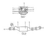
- Figure 7is an end view of the assembly of the first telescopic bone plate.
- Figure 8is a plan view of the telescopic bone plate.
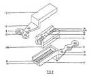
- Figure 9is an exploded perspective view of a further telescopic bone plate.
- Figure 10is a perspective view of the unitary casing and the 5-44UNF thread screw of the further telescopic bone plate.
- Figure 11is a perspective view of the unitary casing and the 5-44UNF thread screw. This view shows the insertion and seating of the 5-44UNF thread screw in the unitary casing.
- Figure 12is a perspective view of an embodiment of the telescopic bone plate fixed at an osteotomy (surgical fracture of the bone) site.
- Figure 13is a plan view of the embodiment of the telescopic bone plate.
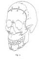
- Figure 14is a perspective view which shows the telescopic bone plates placed at osteotomy (surgical fracture of the bone) sites in the craniofacial skeleton.
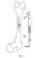
- Figure 15is a perspective view which shows a telescopic bone plate placed at an osteotomy site in a long bone.
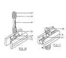
- Figure 16is a cross sectional view of the posterior Jack screw of the embodiment for superior inferior adjustment of the telescopic bone plate..
- Figure 17is a cross sectional anterior view of the anterior Jack screw of the embodiment for medial lateral adjustment of the telescopic bone plate.
- Altuna, Walker and Freemanused the first intra-oral distraction device to lengthen the mandible by using the principles of distraction osteogenesis and sagittal split osteotomy in primates.
- a distractorwas fabricated from a Glen-Ross screw with an opening capacity of 13 mm.
- the screwwas soldered between two mini stainless steel bone plates.
- the bone plateswere adjusted so that the Glen-Ross screw was at the same level as the mandibular occlusal plane.
- the posterior part of the screwwas located 2 to 3 mm. from the gingival (gum) tissues and the anterior part was located 4 to 5 mm. from the gingival tissues. This was done to produce a force vector that would prevent the lateral displacement of the mandibular condyles (jaw joint).
- Each bone platewas fixed to both right and left proximal and distal mandibular segments by six self-tapping bicortical screws, and the surgical sites were closed with 4-0 gut sutures.
- This devicewas stable during both the experimental and post-retention periods. There was no infection or scar tissue formation. The device was easy to activate and was tolerated well by the animal. Its construction made it possible to control the activation forces on two planes, sagitally and laterally. Histological analysis of the temporomandibular joints and the surgical site at the end of the experiment indicated that bone was deposited at the surgical site and that there was no joint pathology.
- the telescopic bone plateconsists of top and bottom bone plates integrated with a telescopic means, which in a preferred mode, is a thread screw assembly.
- the 5-44UNF thread screwis a type of screw which includes a thread at each of the ends of its shaft.
- the casing for the telescopic meansis a unitary screw casing.
- the top bone plateis an extension of the top panel and the bottom bone plate is an extension of the bottom panel.
- the bottom panel and the top panelmay be inclined relative to each other, creating an offset step. Slits may also be made in the top or bottom bone plates to allow for contouring of the plates to fit a curved bone surface.
- An extended bone platemay be used so that more screws can be placed posteriorly and anteriorly to increase stabilization of the device.
- a preferred embodiment of the inventionhas additional components to permit activation of the device in multiple directions. These components allow modification of the vector of distraction of the appliance in a medial lateral plane and a superior inferior plane. Modifying the vector of distraction varies the path along which osteogenesis occurs by changing the direction and final position of the top bone plate and the bottom bone plate. This is particularly important in establishing final occlusion when distracting the mandible. Such precise control over the telescopic bone plate ensures optimal bone growth in the patient.
- This embodimenthas an anterior adjustable screw oriented in a medial lateral plane to adjust the relative positions of the top and bottom bone plates. This screw is actuated through a small anterior incision in the mucosa.
- a posterior adjustable screwmay be oriented in a superior inferior plane to adjust the relative positions of the top and bottom bone plates. This screw is actuated through a small posterior incision in the mucosa.
- the hexagonal surface of the 5-44UNF thread screwcomprises a socket which may be actuated with a standard hexagonal key. Each rotation of the screw produces a 1.1 mm expansion of the device.
- the height and width of the telescopic bone platemay be varied to change the compressive load against the muscles of mastication.
- the depth of the hexagonal socketmay be altered for ease of actuation with a hexagonal key.
- This telescopic bone plateis small enough to be used in the treatment of children with craniofacial defects. It can be surgically placed, covered by the oral mucosa, actuated through windows in the mucosa and completely covered and retained after actuation. The device enables the patient to well tolerate distraction of the bone.
- the telescopic bone plate described herehas direct control of the bony segments.
- the top and bottom panelsare integrated into the thread screw assembly with no welded components and give the device a very low profile (height of approximately 5.175 mm).
- the telescopic bone plateis telescopic whereby one unit of travel can be achieved by adding only half of the unit to the overall body length.
- the dove-tail interlocking track designis unique allowing for smooth operation and lateral stability.
- the bone platescan be customized to suit the surgical site and all specifications are disclosed, including a compressive strength of 1,290 N.
- the devicepossesses three force vectors, sagittal, lateral and superior-inferior and was tested successfully in primates.
- the telescopic bone plateis implanted intraorally and is actuated intraorally via a window in the mucosa of the mouth.
- the hexagonal surface of the 5-44UNF thread screwis only exposed for the actuation period (10 days).
- the windowis allowed to heal after actuation. There is no risk of pin-tract infection or scar formation.
- Figure 1shows the telescopic bone plate which consists of a top thread 1, a top panel 2, a customized top bone plate 3 integrated into the top panel; a bottom thread 4, a bottom panel 5, and a customized bottom bone plate 6 integrated into the bottom panel.
- the top bone plate 3 and the bottom bone plate 6are depicted in cut-away form for purposes of Figures 4 and 5.
- Figure 8shows a typical top bone plate 3 and bottom bone plate 6.
- the shape of the top and bottom bone plates 3, 6may be adjusted as needed and does not limit the scope of this invention.
- the top and bottom panels 2, 5 of the telescopic bone plate as well as the top screw casing 11 and the bottom screw casing, 12employ a specially shaped "dove-tail " interlocking design 7 (Figs.
- the telescopic meansis a thread screw assembly.
- the thread screw assemblycontains a 5-44UNF thread screw 15 which is threaded at both ends 9, 10 (Figs. 1, 4, 5)).
- the 5-44UNF thread screw 15is retained in a top screw casing 11 and a bottom screw casing 12, which are locked together by a pair of dowel pins 13 through holes 16 in the top screw casing 11 and holes 16 in the bottom screw casing 12 (Figs. 1, 6).
- a hexagonal socket 14is located at the end of the 5-44UNF thread screw 15 for actuation purposes (Figs. 1, 7).
- the top and bottom panels 2, 5along with integrated bone plates 3, 6 slide in opposite directions and by the same amount of travel distance producing a telescopic result. This causes the fractured bone segments to move apart (distract).
- Figure 2shows the telescopic bone plate in a closed position, where the top and bottom bone plates are not separated.
- the top and bottom bone platesare separated, as shown in figure 3.
- Actuationis by using a standard hexagonal key (described in more detail below).
- a second commercial variationwas developed and fabricated.
- This variantis similar to the first and includes changes in the design such as an addition of 1 mm in both width and height of the telescopic bone plate. This results in a higher compressive load against the muscles of mastication.
- the angle between the top panel and the top bone plateis acute; the angle between the bottom panel and bottom bone plate is obtuse. This results in an offset bend (step) of 2mm. This maximizes the frontal vector of the resultant force and enables easier access to the hexagonal surface for actuation.
- the depth of the hexagonal socketis 3 mm. This ensures definitive placement of the standard hexagonal key.
- the metal between the counter-sunk holes in the top and bottom bone platesmay be slit.
- a third variationwas developed and fabricated, as shown in figures 9-11.
- the additional 1 mm in both width and height of the telescopic bone platethere is an offset bend (step) 20 in the front bone plate of 2 mm, a 3 mm deep hexagonal surface 30 and slits 23 in the metal between the holes in the back bone plate.
- the internal geometry of the thread screw assemblyis re-engineered (Figs. 10, 11). It includes a unitary screw casing 31 instead of a two piece casing.
- This unitary screw casing 31contains the 5-44UNF thread screw used in the second embodiment.
- the screw casing 31is easier to manufacture than the screw casing of the first and second embodiments of the invention.
- the unitary screw casing 31is constructed from one piece instead of two and it is not held together by dowel pins.
- the third telescopic bone plateconsists of a top panel 17 with threads integrated into a customized top bone plate 18; a bottom panel 19 with threads 25 with a 2 mm step (offset) 20, integrated into a customized bottom bone plate 21.
- the panel track of the top panel 17receives the unitary screw casing track 24A.
- the panel track 26 of the bottom panelreceives the unitary screw casing track 24B.
- the unitary screw casing 31contains the 5-44UNF thread screw 29 which is threaded at both ends 32, 33 (Fig. 10).
- the 5-44UNF thread screw 29is retained by top brackets 27, and bottom brackets 28 of the unitary screw casing 31 (Fig. 11).
- a 3 mm hexagonal socket 30is located at the end of the 5-44UNF thread screw 29 for actuation. Actuation is by using a standard hexagonal key which is inserted into the hexagonal socket 30 and turned. Upon actuation, the top panel 17 and the bottom panel 19 slide longitudinally in opposite directions, producing a telescopic result. This increases the separation between the top bone plate 18 and the bottom bone plate 21 which causes the fractured bone segments to move apart (distract). Gradual separation permits osteogenesis to occur.
- This embodiment of the telescopic bone plateincorporates five new design features which are shown in Figs. 12 and 13.
- This embodimentallows medial lateral and superior inferior adjustments of the position of the top and bottom bone plates to precisely control osteogenesis. This gives much more variability in the direction in which the bone is being displaced to allow total control of the final position of the distracted mandible. Multi directional adaptability of the vectors of force generated by the device provides greater flexibility for the surgeon because the initial placement of the device becomes less critical.
- This embodimentutilizes a telescopic means similar to that of the third embodiment, described above, to distract bone in an anterior posterior plane.
- This part of the telescopic meansconsists of a unitary casing and a 5-44UNF thread screw 40. The exposed end of the 5-44UNF thread screw 40 with the hexagonal socket 41 is elongated and extends anterior from the telescopic bone plate.
- This embodimentalso has a displacement means at each of its anterior and posterior ends.
- the displacement meansis a Jack screw assembly (Figs. 16, 17).
- other displacment meanscould also be used, such as the 5-44UNF thread screw assembly (telescopic means) described above.
- the posterior end of the telescopic bone platehas a platform 42 that extends from the top bone plate 43 (Figs. 12, 16). This platform 42 has an aperture which receives one end of a posterior screw 45.
- This end of the posterior screw 45has a smooth, non-threaded rotating surface 61 which is between a first collar 44A and a second collar 44B.
- This rotating surface 61is received in the aperture and held in place by the first collar 44A and the second collar 44B (Fig. 16).
- the smooth, non-threaded rotating surfaceprovides increased stability, rigidity and strength. This design will also lessen the likelihood of the screw coming loose during activation. Additionally, the strength requirements of the entire applicance under activation in different vectors will be borne by the threads of the screw and the threads of the appliance itself.
- the other end of the posterior screw 45is received in a stage 46 fixed to the top panel 47.
- the stage 46has a threaded aperture49.
- the posterior screw 45has its longitudinal axis in a superior inferior plane.
- the end of the posterior screw 45 received by the stage 46has a hexagonal socket 48.
- a hexagonal key with a right angle offset bendis inserted in the hexagonal socket 48 to turn the posterior screw 45 and move the relative position of the platform 42 and the stage 46 in a superior inferior plane.
- using the hexagonal key to turn the posterior screw 45 in one directionwill separate the platform 42 and the stage 46.
- Turning the posterior screw 45 in the opposite directionwill decrease the distance between the platform 42 and stage 46.
- the anterior end of the appliancehas a platform 50 that extends from the bottom bone plate 51 (Figs. 12, 17).
- This platformhas an aperture which receives one end of an anterior screw 53.
- This end of the anterior screw 53has a smooth, non-threaded rotating surface 62 which is between a third collar 52A and a fourth collar 52B. This rotating surface 62 is received in the aperture and held in place by the third collar 52A and the fourth collar 52B (Fig. 17).
- the other end of the anterior screw 53is received in a threaded opening 54 in a stage 55.
- the stage 55is fixed to the bottom panel 56.
- the anterior screw 53has its longitudinal axis in a medial lateral plane.
- the end of the anterior screw 53 received by the stage 55has a hexagonal socket 59.
- a hexagonal keyis inserted in the hexagonal socket 59 to turn the anterior screw 53 and move the relative position of the platform 50 and the stage 55 in a medial lateral plane. For example, using the hexagonal key to turn the anterior screw 53 in one direction will separate the platform 50 and the stage 55. Turning the anterior screw 53 in the opposite direction will decrease the distance between the platform 50 and stage 55.
- This embodimentalso has a longer top bone plate 43 and bottom bone plate 51 to allow the use of more screws 57 to attach the device for improved stabilization.
- the screw holes 58 in the top and bottom bone plates 43, 51accommodate fastening means, such as 2 mm self tapping screws.
- Improved stabilization of the telescopic bone plateprevents loosening of the screws and slippage of the device. Improving stabilization makes the telescopic bone plate particularly effective in larger bone systems where greater forces are generated, for example bones of the legs or arms. In these parts, the bones are heavier than those in the face and subject to significant forces by the patient's movements.
- top and bottom bone plates 43, 51are offset in this embodiment so that they are superior to the top panel and the bottom panel 47, 56. This shift in position simplifies actuation of the device. It also allows the use of top and bottom bone plates 43, 51 that are significantly longer than those of earlier embodiments without increasing the overall length of the telescopic bone plate.
- the telescopic bone plate for distraction osteogenesisis small and can be placed in an open procedure transorally.
- the telescopic bone platecan be adapted to individual anatomical contours.
- the deviceis designed to be placed and covered sub mucosally. It is accessed through a remote small access site in the mucosa for actuation. Because the plate is completely tissue covered, it offers many advantages over previous distractors. It avoids potential complications including wound dehiscence, chronic ingress or oral bacteria, potential for infection or loosening of the device and further adverse effects on the bony healing during distraction osteogenesis.
- osteotomysurgical fracture of the bone
- Other osteotomy designs that can be usedalso include body osteotomy or ramus osteotomy.
- This standard transoral approach to the mandibleis utilized as an open procedure.
- Complete subperiosteal dissectionis carried out exposing the lateral aspect of the mandible and the ramus.
- Medial dissectionis carried out enabling a horizontal medial cortex osteotomy to be created.
- An anterior ramus osteotomyis created as well as a lateral cortex osteotomy. It is advisable at this stage to contour and place the device prior to actual splitting of the mandible. This allows correct orientation of the segments and condylar position.
- 1-2 screws in either bony segmentare placed initially. This provides solid reference for reapplying the bone plate at a later time.
- the preferred fastening means for stabilizing the plate to the mandiblecomprises stainless steel 2.0 mm self tapping screws.. Initial screw placement is monocortical as initial screws are utilized to temporarily stabilize the appliance in its desired position.
- the sagittal split osteotomy(fracture) is completed in the usual fashion with the osteotome technique. Some bony sculpting may be necessary to allow passivity of the segments for antero/postero distraction osteogenesis. Some degree of muscle stripping is carried out as well to ensure passivity of the segments.
- the deviceis then reapplied utilizing the previously drilled holes.
- the telescopic bone plateis attached to bone using fastening means, such as monocortical or bicortical screws. A depth gauge can be used but the screws should be bicortical in the anterior part of the mandible.
- the ramusis somewhat thin and essentially as long as the screws are placed in an area that does not interfere with the sliding osteotomy design they can be either monocortical or bicortical. It is recommended that the device be placed at the inferior border of the mandible. Posterior access can be percutaneous through unbroken skin with a small stab incision. The device is placed at the inferior border of the mandible to avoid the inferior alveolar neurovascular bundle and the roots of the teeth. It is advisable to place 3 screws per bony segment. The device should be at its zero position when applied to the mandible. After it is applied to the mandible it is opened 2-4 mm to observe the movement of the bony segments. The device is then closed back to 0 mm, tissues are closed with 2 layer closure in a water tight fashion. A similar procedure is carried out for the contra lateral side of the mandible.
- a standard incisionis made from the anterior mid ramus up to the bicuspid region, care being taken to be out in the vestibule.
- Sharp dissectionis carried out bone to bone.
- a sub periosteal dissectionis carried out exposing the lateral aspect of the ramus.
- Careful minimal strippingwas carried out on the medial aspect of the mandible just distal to the dentition.
- a locationis identified for the osteotomy site.
- a bony window in the lateral cortexis carefully outlined with a 701 burr and gently removed with an osteotome. This allows exposure of the inferior alveolar neuro-vascular bundle. Once this is identified, a planned area for osteotomy cut can be made.
- the telescopic bone plateis contoured to fit the lateral aspect of the mandible. It is important to ensure that the correct vector or alignment of the appliance is achieved such that the vector of distraction is the one desired. Once this is carried out monocortical screws are utilized one to two at either end of the appliance to secure its position. Posterior screws are often placed with a percutaneous trocar due to limited intra oral access.
- the applianceis removed and the body ramus osteotomy is completed with a 701 burr. Care is taken to avoid minimal stripping of the mucoperiosteum an the medial aspect of the mandible.
- the osteotomyis completed with an osteotome. Once the osteotomy is completed the telescopic bone plate can be re-applied utilizing the previously drilled holes.
- a depth gaugecan be utilized to measure appropriate thickness, a minimum of three screws per segment, four to six screws may be possible in the posterior segment. Wounds are irrigated and closure is recommended with interrupted vertical and/or horizontal mattress sutures with non resorbable suture material.
- Actuationcan begin between the fourth to seventh day after osteotomy.
- a small stab incisionis made in the anterior portion of the vestibule.
- Blunt dissectionis carried out down to the activating portion of the appliance where the hexagonal key is inserted.
- the hexagonal keyis introduced and under direct visualization is opened 1.1 mm per day until the desired lengthening of bone is achieved.
- the appliancewould normally be removed three months after distraction is complete. This should be accomplished via trans oral incision with sub periosteal dissection and removal of screws and subsequently appliance. Posterior screws may be removed by percutaneous technique. The surgical site is irrigated and closed with interrupted sutures.
- Actuation of the telescopic bone plateusually occurs approximately 4-10 days post placement. This allows primary wound healing.
- a small stab incision with blunt dissectionis carried out at the site of the hexagonal socket of the device.
- a standard hexagonal keyis placed into the hexagonal socket and turned to actuate the device in order to longitudinally displace the top bone plate and the bottom bone plate relative to each other by 1.1 mm per day until the desired degree of distraction osteogenesis is carried out.
- Actuation of the anterior screw through the anterior stab incisionis accomplished by using a hexagonal key. One complete revolution of the screw would result in 1.1mm of distraction.
- Actuation of the posterior screwwould involve a small stab incision superior to the appliance in the posterior region with blunt dissection down to the hexagonal surface.
- the first embodiment of the telescopic bone platewas tested in a primate. A sagittal split osteotomy of the mandible was carried out. Bilateral telescopic bone plates were placed at the right and left osteotomy sites with bone screws. The mucosa was closed to cover the device. Ten days later a window was made in the mucosa exposing the hexagonal socket at the front end of the screw of the device. Actuation by a standard hexagonal key at a rate of 1.1 mm a day was carried out for ten days. At the end of the actuation period, the window in the mucosa was allowed to heal. The mandible was successfully advanced. During the retention period the animal thrived, gained weight and did not present any evidence of infection or scar formation. Histological analysis revealed bony union of the distracted mandible segments.
- the second and third embodimentswere also tested in a primate.
- a sagittal split osteotomy of the right side of the mandible and an osteotomy of the ramus of the left side of the mandiblewas carried out.
- the second embodimentwas placed at the right osteotomy site with bone screws and the third embodiment was placed at the left osteotomy site with bone screws.
- the mucosawas closed to cover each device. Seven days later a window was made in the mucosa exposing the hexagonal socket at the front end of the screw of each of the devices. Actuation by a standard hexagonal key at a rate of 1.1 mm a day was carried out for 9 days.
- the window in the mucosawas allowed to heal.
- the mandiblewas successfully advanced and distraction osteogenesis occurred.
- the animalthrived, gained weight and did not present any evidence of infection or scar formation. Histological analysis revealed bony union of the distracted mandibular segments and normal temporomandibular joints.
- Mid face retrusionis a commonly occurring dental/facial deformity.
- Distraction osteogenesis of the anterior maxilla with a telescopic bone platecan be carried out predictably with excellent bone formation and no adverse effects.
- the maxillais a membranous bone with numerous vertical walls including the lateral wall of the maxilla, the medial wall of the maxillary sinus, nasal septum and vomer and contra lateral medial sinus wall and lateral maxillary wall. Additionally there is the bony interface between the posterior wall of the maxilla and the pterygoid plates.
- Distraction osteogenesis of the maxillamay be utilized at the Le Fort I level.
- Le Fort I osteotomy including the lateral nasal wall, medial wall, separation of septum and vomer as well as separating the maxilla from the pterygoid plateswould be accomplished with subsequent application of intra oral distraction device previously described. Modifications to the device would be necessary based on the anatomical considerations of the maxilla.
- the initial osteotomy cuts and placement of the sub mucosal applianceare accomplished.
- the applianceis exposed at approximately one week post osteotomy cuts and activated 1.1 mm a day for a total of 10 mm of advancement. All surgical procedures are carried out under general anesthesia. Patients are maintained on soft diet minimal chewing during the follow up period.
- top and bottom panels with their integrated bone platesare manufactured by erosive die sinking and erosive cutting.
- the thread screw assemblywas manufactured by high speed lathe and erosive die sinking. All components were made out of Type 316 stainless steel.
- Stainless steel Type 316is the material for severe corrosive conditions, as it has an exceptional characteristic of corrosion resistance. In addition, good abrasion resistance and cold forming makes it a good choice for this application.
- Erosive die sinkingis a pure reproduction of the shape of the electrode whereas erosive cutting employs an electrolytic copper or brass wire moving over the workpiece surface thus producing a type of "cut".
- top and bottom bone platesare I mm thick. They can be customized with respect to their design and number of holes to suit the surgical site.
Landscapes
- Health & Medical Sciences (AREA)
- Orthopedic Medicine & Surgery (AREA)
- Life Sciences & Earth Sciences (AREA)
- Surgery (AREA)
- Medical Informatics (AREA)
- Engineering & Computer Science (AREA)
- Biomedical Technology (AREA)
- Heart & Thoracic Surgery (AREA)
- Nuclear Medicine, Radiotherapy & Molecular Imaging (AREA)
- Molecular Biology (AREA)
- Animal Behavior & Ethology (AREA)
- General Health & Medical Sciences (AREA)
- Public Health (AREA)
- Veterinary Medicine (AREA)
- Surgical Instruments (AREA)
- Prostheses (AREA)
- Orthopedics, Nursing, And Contraception (AREA)
Description
| First Plate | Second and Third Plates | |
| Collapsed length = | 13.00 mm | 13.00 mm |
| Width = | 7.00 mm | 8.00 mm |
| Height = | 4.15 mm | 5.16 mm |
| Weight = | 5 grams | 5.5 grams |
| Expanded length (overall) = | 27 | 27 mm |
| Compressive strength (ultimate) = | 1,290N (tested on expansion screw without bone plates) | 1450N |
| # of engaged threads = | 5 per | 5 per side |
| Linear travel = | 1.15 mm/turn | 1.15 mm/turn |
Claims (17)
- A telescopic bone plate for distracting osteotomicallyseparated bone sections, the plate comprising:
a top bone plate (43) and a bottom bone plate (51)adjustable relative to each other, and the top bone plate(43) and the bottom bone plate (51) each including means(57) for fastening the telescopic bone plate to bone;
characterized in thatthe top bone plate (43) and the bottom bone plate (51) areadjustable relative to each other in at least two of amedial lateral direction, a superior inferior direction andan anterior posterior direction; andat least two displacement means (40, 45, 53) arranged in atleast two of a medial lateral direction, a superiorinferior direction and an anterior posterior direction areprovided for adjusting telescopically the relativepositions of the top bone plate (43) and bottom bone plate(51) to each other in at least two of a medial lateralplane, a superior inferior plane, and an anterior posteriorplane. - The telescopic bone plate according to claim 1, includingthree displacement means (40, 45, 53) for adjusting therelative positions of the top bone plate (43) and thebottom bone plate (51) to each other in said medial lateralplane, said superior inferior plane and said anteriorposterior plane.
- The telescopic bone plate according to claim 1 or 2 for implantation in an oral cavity, wherein the displacementmeans (40, 45, 53) are located in said oral cavity.
- The telescopic bone plate according to claim 3, furtherincluding actuating means (41, 48, 59) for actuating thedisplacement means (40, 45, 53) to adjust the relativepositions of the top (43) and bottom (51) bone plates, theactuating means (41, 48, 59) being coupled to thedisplacement means (40, 45, 53) and being located in saidoral cavity.
- The telescopic bone plate of claim 1, wherein the firstdisplacement means (40) is a telescopic means which isactuated in an anterior posterior plane.
- The telescopic bone plate of claim 5, wherein the seconddisplacement means (45) is actuated in a superior inferiorplane.
- The telescopic bone plate of claim 5, wherein the seconddisplacement means (53) is actuated in a medial lateralplane.
- The telescopic bone plate of claim 1 or claim 2, whereinthe top bone plate further comprises a top panel (47) andthe bottom bone plate (51) further comprises a bottom panel(56), wherein the top panel (47) overlays the bottom panel(56) and wherein the first displacement means (40) islocated between the top panel (47) and the bottom panel(56).
- The telescopic bone plate of any of claims 1 to 8, whereinafter implanation, the bone plate is completely coveredwith tissue of a patient.
- The telescopic bone plate of any of claims 1 to 9,including a control means located outside of a patient'sbody for actuating the displacement means (40, 45, 53) to adjust the relative positions of the top (43) and bottom(51) bone plates relative to one another.
- The telescopic bone plate of any of claims 1 to 10, whereinthe bone plate has a compressive strength of at least 1,290N.
- The telescopic bone plate of any of claims 1 to 11, whereinthe bone plate consists of stainless steel.
- The telescopic bone plate of any of claims 1 to 12, whereinthe bone plate has a profile of less than 6 mm.
- The telescopic bone plate of any of claims 1 to 13, whereinone of the bottom bone plate (51) and the top bone plate(43) are inclined relative to the other.
- The telescopic bone plate of any of claims 1 to 14, whereinthe adjustable distance between the top (43) and the bottom(51) bone plates is at least 10 mm.
- The telescopic bone plate of any of claims 1 to 15, whereinthe displacement means are actuated by a motor.
- The telescopic bone plate of claim 1, wherein thetelescopic bone plate has a longitudinal axis and a lateralaxis;the medial lateral direction is substantially parallel tothe lateral axis of the telescopic bone plate, the superiorinferior direction is substantially perpendicular to boththe longitudinal axis and the lateral axis of thetelescopic bone plate, and the anterior posterior directionis substantially parallel to the longitudinal axis of thetelescopic bone plate; andthe medial lateral plane, the superior inferior plane, andthe anterior posterior plane are mutually perpendicular.
Applications Claiming Priority (3)
| Application Number | Priority Date | Filing Date | Title |
|---|---|---|---|
| US784795P | 1995-12-01 | 1995-12-01 | |
| US7847P | 1995-12-01 | ||
| PCT/CA1996/000779WO1997020512A1 (en) | 1995-12-01 | 1996-11-27 | Telescopic bone plate for use in bone lenghtening by distraction osteogenesis |
Publications (2)
| Publication Number | Publication Date |
|---|---|
| EP0865258A1 EP0865258A1 (en) | 1998-09-23 |
| EP0865258B1true EP0865258B1 (en) | 2000-06-21 |
Family
ID=21728427
Family Applications (1)
| Application Number | Title | Priority Date | Filing Date |
|---|---|---|---|
| EP96938881AExpired - LifetimeEP0865258B1 (en) | 1995-12-01 | 1996-11-27 | Telescopic bone plate for use in bone lengthening by distraction osteogenesis |
Country Status (6)
| Country | Link |
|---|---|
| US (1) | US5902304A (en) |
| EP (1) | EP0865258B1 (en) |
| AU (1) | AU715921B2 (en) |
| CA (1) | CA2191405C (en) |
| DE (1) | DE69608968T2 (en) |
| WO (1) | WO1997020512A1 (en) |
Families Citing this family (193)
| Publication number | Priority date | Publication date | Assignee | Title |
|---|---|---|---|---|
| US5984925A (en)* | 1997-07-30 | 1999-11-16 | Cross Medical Products, Inc. | Longitudinally adjustable bone plates and method for use thereof |
| RU2143242C1 (en)* | 1998-07-07 | 1999-12-27 | Амурский государственный университет | Device for epiosseous osteosynthesis |
| DE19856062A1 (en)* | 1998-12-04 | 2000-06-15 | Wittenstein Gmbh & Co Kg | Distraction device |
| US6306143B1 (en)* | 1999-01-19 | 2001-10-23 | Nobel Biocere Ab | Distraction osteogenesis fixture |
| EP1027868A1 (en)* | 1999-02-09 | 2000-08-16 | Paul A. Dr. med. Müller | Traction device for the adjustment of an upper jaw |
| US6423069B1 (en)* | 1999-03-23 | 2002-07-23 | Synthes (Usa) | Orthopedic system having detachable bone anchors |
| JP2001037767A (en)* | 1999-08-02 | 2001-02-13 | Kyowa Tokei Kogyo Kk | Bone adjuster |
| US6673079B1 (en) | 1999-08-16 | 2004-01-06 | Washington University | Device for lengthening and reshaping bone by distraction osteogenesis |
| US6383189B1 (en)* | 1999-09-13 | 2002-05-07 | Brian Schumacher | Driver tool for bone distractor with shaft extension |
| EP1099415A1 (en)* | 1999-11-10 | 2001-05-16 | Ulrich Dr. Dr. Longerich | Bone distractor with an adjustment device |
| WO2001041662A1 (en) | 1999-12-09 | 2001-06-14 | Macropore | Completely resorbable connective tissue distraction devices and techniques |
| BE1013222A3 (en)* | 2000-01-11 | 2001-11-06 | Mommaerts Maurice Yves | APPARATUS FOR INTRA-ORAL DISTRACTIEOSTEOTOMIE to widen the upper jaw. |
| US6678562B1 (en) | 2000-01-12 | 2004-01-13 | Amei Technologies Inc. | Combined tissue/bone growth stimulator and external fixation device |
| USD460184S1 (en) | 2000-01-28 | 2002-07-09 | Stephen A. Schendel | Bone distraction device |
| DE20004588U1 (en)* | 2000-03-11 | 2001-07-26 | Engelke, Wilfried, Prof. Dr.Dr.med., 37130 Gleichen | Anchored cylindrical alveolar distractor |
| US6423061B1 (en) | 2000-03-14 | 2002-07-23 | Amei Technologies Inc. | High tibial osteotomy method and apparatus |
| KR200196064Y1 (en)* | 2000-04-17 | 2000-09-15 | 정규림 | The brace for the orthodontic treatment after the corticotomy |
| BE1013397A3 (en)* | 2000-04-19 | 2001-12-04 | Mommaerts Maurice | APPARATUS FOR INTRA-ORAL DISTRACTIEOSTEOTOMIE to broaden the lower jaw. |
| US7771482B1 (en) | 2000-05-09 | 2010-08-10 | Ben-Zion Karmon | Method for tissue expansion and regeneration using bioresorbable inflatable devices |
| AU2001280476B2 (en) | 2000-06-30 | 2005-11-24 | Stephen Ritland | Polyaxial connection device and method |
| US6908469B2 (en) | 2000-10-04 | 2005-06-21 | Synthes (Usa) | Compact maxillary distractor |
| US6872210B2 (en) | 2001-02-23 | 2005-03-29 | James P. Hearn | Sternum fixation device |
| WO2002080823A1 (en)* | 2001-04-04 | 2002-10-17 | Rapp Lawrence G | Interbody spinal fusion device |
| CA2443269A1 (en)* | 2001-04-04 | 2002-10-31 | Lawrence G. Rapp | Mobile sleeve structure for maintaining spatial relationship between vertebrae |
| US7537604B2 (en)* | 2002-11-19 | 2009-05-26 | Acumed Llc | Bone plates with slots |
| US20050240187A1 (en) | 2004-04-22 | 2005-10-27 | Huebner Randall J | Expanded fixation of bones |
| US7717945B2 (en) | 2002-07-22 | 2010-05-18 | Acumed Llc | Orthopedic systems |
| US7326212B2 (en) | 2002-11-19 | 2008-02-05 | Acumed Llc | Bone plates with reference marks |
| CA2443429C (en) | 2001-06-04 | 2010-08-10 | Gary Karlin Michelson | Anterior cervical plate system having vertebral body engaging anchors, connecting plate, and method for installation thereof |
| JP4283665B2 (en)* | 2001-06-04 | 2009-06-24 | ウォーソー・オーソペディック・インコーポレーテッド | Dynamic plate for anterior cervical spine with movable segments |
| US7186256B2 (en)* | 2001-06-04 | 2007-03-06 | Warsaw Orthopedic, Inc. | Dynamic, modular, single-lock anterior cervical plate system having assembleable and movable segments |
| US7097645B2 (en)* | 2001-06-04 | 2006-08-29 | Sdgi Holdings, Inc. | Dynamic single-lock anterior cervical plate system having non-detachably fastened and moveable segments |
| US7041105B2 (en)* | 2001-06-06 | 2006-05-09 | Sdgi Holdings, Inc. | Dynamic, modular, multilock anterior cervical plate system having detachably fastened assembleable and moveable segments |
| US7044952B2 (en)* | 2001-06-06 | 2006-05-16 | Sdgi Holdings, Inc. | Dynamic multilock anterior cervical plate system having non-detachably fastened and moveable segments |
| DE60238997D1 (en)* | 2001-09-28 | 2011-03-03 | Stephen Ritland | CHROME OR HOOKS |
| US7261713B2 (en)* | 2001-10-09 | 2007-08-28 | Synthes (Usa) | Adjustable fixator |
| US7621922B2 (en)* | 2001-11-20 | 2009-11-24 | Osteomed L.P. | Facial osteodistraction device |
| US7892241B2 (en) | 2001-11-20 | 2011-02-22 | Osteomed, L.P. | Method and system for facial osteodistraction using a cannulated device |
| US6758673B2 (en) | 2001-12-05 | 2004-07-06 | Ofir Fromovich | Periosteal distraction |
| ATE476930T1 (en) | 2002-02-20 | 2010-08-15 | Stephen Ritland | DEVICE FOR CONNECTING HAND SCREWS |
| DE10212815A1 (en)* | 2002-03-22 | 2003-10-02 | Ernst Fuchs | Distraction device for osteogenesis |
| US6966910B2 (en)* | 2002-04-05 | 2005-11-22 | Stephen Ritland | Dynamic fixation device and method of use |
| EP1385436A1 (en)* | 2002-04-09 | 2004-02-04 | Medartis AG | Distractor |
| ATE552789T1 (en) | 2002-05-08 | 2012-04-15 | Stephen Ritland | DYNAMIC FIXATION DEVICE |
| US20030233093A1 (en)* | 2002-06-13 | 2003-12-18 | Randall Moles | Osteogenic distraction device |
| AU2002321153A1 (en)* | 2002-07-01 | 2004-01-19 | Faceworks Solutions & Technologies Ltd. | Radial osteogenic distractor device |
| CN1309352C (en)* | 2002-07-22 | 2007-04-11 | 精密医疗责任有限公司 | Bone fusion system |
| WO2004008978A1 (en)* | 2002-07-24 | 2004-01-29 | Nas Spine, Inc. | Compressible fixation apparatus for spinal surgery |
| AU2003294342A1 (en) | 2002-11-19 | 2004-06-15 | Acumed Llc | Guide system for bone-repair devices |
| AU2003294414B2 (en)* | 2002-11-19 | 2009-03-12 | Acumed Llc | Deformable bone plates |
| EP1596738A4 (en)* | 2003-02-25 | 2010-01-20 | Stephen Ritland | Adjustable rod and connector device and method of use |
| WO2004110247A2 (en) | 2003-05-22 | 2004-12-23 | Stephen Ritland | Intermuscular guide for retractor insertion and method of use |
| WO2004112587A2 (en) | 2003-06-20 | 2004-12-29 | Acumed Llc | Bone plates with intraoperatively tapped apertures |
| US7635365B2 (en) | 2003-08-28 | 2009-12-22 | Ellis Thomas J | Bone plates |
| US7857839B2 (en)* | 2003-09-03 | 2010-12-28 | Synthes Usa, Llc | Bone plate with captive clips |
| US20050049595A1 (en)* | 2003-09-03 | 2005-03-03 | Suh Sean S. | Track-plate carriage system |
| US7909860B2 (en) | 2003-09-03 | 2011-03-22 | Synthes Usa, Llc | Bone plate with captive clips |
| US20050085818A1 (en)* | 2003-10-17 | 2005-04-21 | Huebner Randall J. | Systems for distal radius fixation |
| US7182785B2 (en)* | 2004-03-11 | 2007-02-27 | Craniotech Acr Devices, Llc | Mandibular bone transport reconstruction plate |
| US20050234448A1 (en)* | 2004-03-19 | 2005-10-20 | Mccarthy James | Implantable bone-lengthening device |
| WO2005102193A2 (en) | 2004-04-19 | 2005-11-03 | Acumed, Llc | Placement of fasteners into bone |
| US7485121B2 (en)* | 2004-05-04 | 2009-02-03 | Synthes (Usa) | Midface distractor |
| US7686836B2 (en)* | 2004-05-13 | 2010-03-30 | Kls-Martin, L.P. | Bone distractor and method |
| US7540874B2 (en)* | 2004-05-27 | 2009-06-02 | Trimed Inc. | Method and device for use in osteotomy |
| US7604638B2 (en)* | 2004-06-21 | 2009-10-20 | Depuy Spine, Inc. | Instruments and methods for holding a bone plate |
| US7481841B2 (en)* | 2004-06-30 | 2009-01-27 | Depuy Products, Inc. | Adjustable orthopaedic prosthesis and associated method |
| US7955357B2 (en) | 2004-07-02 | 2011-06-07 | Ellipse Technologies, Inc. | Expandable rod system to treat scoliosis and method of using the same |
| US7875033B2 (en)* | 2004-07-19 | 2011-01-25 | Synthes Usa, Llc | Bone distraction apparatus |
| US7854752B2 (en) | 2004-08-09 | 2010-12-21 | Theken Spine, Llc | System and method for dynamic skeletal stabilization |
| US20060058798A1 (en)* | 2004-08-24 | 2006-03-16 | Roman Shawn D | Bone distractor with ratchet mechanism |
| US7455639B2 (en) | 2004-09-20 | 2008-11-25 | Stephen Ritland | Opposing parallel bladed retractor and method of use |
| US7559951B2 (en) | 2004-09-30 | 2009-07-14 | Depuy Products, Inc. | Adjustable, remote-controllable orthopaedic prosthesis and associated method |
| US9615866B1 (en) | 2004-10-18 | 2017-04-11 | Nuvasive, Inc. | Surgical fixation system and related methods |
| US8388553B2 (en) | 2004-11-04 | 2013-03-05 | Smith & Nephew, Inc. | Cycle and load measurement device |
| WO2006058221A2 (en) | 2004-11-24 | 2006-06-01 | Abdou Samy M | Devices and methods for inter-vertebral orthopedic device placement |
| US7635364B2 (en) | 2004-12-01 | 2009-12-22 | Synthes Usa, Llc | Unidirectional translation system for bone fixation |
| WO2006108160A1 (en)* | 2005-04-06 | 2006-10-12 | Stevens Institute Of Technology | Intra-oral distraction device |
| US8152834B2 (en)* | 2005-04-13 | 2012-04-10 | Synthes Usa, Llc | Forceps and system using same |
| JP4988735B2 (en) | 2005-07-19 | 2012-08-01 | リットランド、ステファン | Rod extension for elongating fusion structures |
| US9849216B2 (en) | 2006-03-03 | 2017-12-26 | Smith & Nephew, Inc. | Systems and methods for delivering a medicament |
| RU2329776C2 (en)* | 2006-03-10 | 2008-07-27 | Закрытое акционерное общество Московский центр детской челюстно-лицевой хирургии | Method of elimination of congenital or acquired deformation and/or hypoplasia of zygomatic bone and related device for zygomatic region relief and volume restoration |
| US8025681B2 (en) | 2006-03-29 | 2011-09-27 | Theken Spine, Llc | Dynamic motion spinal stabilization system |
| US7775020B2 (en)* | 2006-05-02 | 2010-08-17 | Illinois Tool Works Inc. | Bar code blocking package |
| US7500851B2 (en)* | 2006-07-01 | 2009-03-10 | Williams Michael O | Maxillary arch expander unbanded to teeth |
| US7959564B2 (en)* | 2006-07-08 | 2011-06-14 | Stephen Ritland | Pedicle seeker and retractor, and methods of use |
| RU2346669C2 (en)* | 2006-09-01 | 2009-02-20 | Николай Геннадьевич Бобылев | Sliding lower jaw implant |
| US20080065073A1 (en)* | 2006-09-08 | 2008-03-13 | Michael Perriello | Offset dynamic motion spinal stabilization system |
| RU2332189C2 (en)* | 2006-10-16 | 2008-08-27 | Государственное учреждение Московский областной научно-исследовательский клинический институт им. М.Ф. Владимирского | Device for lower jaw condylar process replacement |
| US7862502B2 (en) | 2006-10-20 | 2011-01-04 | Ellipse Technologies, Inc. | Method and apparatus for adjusting a gastrointestinal restriction device |
| US8568453B2 (en)* | 2007-01-29 | 2013-10-29 | Samy Abdou | Spinal stabilization systems and methods of use |
| US7722560B2 (en)* | 2007-02-09 | 2010-05-25 | The Regents Of The University Of Michigan | Mechanical extension implants for short bowel syndrome |
| US9445720B2 (en) | 2007-02-23 | 2016-09-20 | Smith & Nephew, Inc. | Processing sensed accelerometer data for determination of bone healing |
| US7744649B2 (en)* | 2007-06-25 | 2010-06-29 | Moore Mark R | Spondylolisthesis correction apparatus and method |
| US20090131987A1 (en)* | 2007-09-18 | 2009-05-21 | Anthem Orthopaedics Llc | Bone reduction device and method utilizing same |
| US20090093820A1 (en)* | 2007-10-09 | 2009-04-09 | Warsaw Orthopedic, Inc. | Adjustable spinal stabilization systems |
| US20090112262A1 (en) | 2007-10-30 | 2009-04-30 | Scott Pool | Skeletal manipulation system |
| WO2009062522A2 (en)* | 2007-11-18 | 2009-05-22 | Khaled Mohamed Emara | Bone lengthening plate |
| US11202707B2 (en) | 2008-03-25 | 2021-12-21 | Nuvasive Specialized Orthopedics, Inc. | Adjustable implant system |
| US20100075270A1 (en)* | 2008-09-19 | 2010-03-25 | Figueroa Alvaro A | Angularly adjustable maxillary distractor and method of distraction |
| RU2387410C1 (en)* | 2008-09-29 | 2010-04-27 | Дмитрий Александрович Никитин | Device for elimination of defects and deformities of lower jaw bone |
| US12285197B2 (en) | 2008-10-10 | 2025-04-29 | Acumed Llc | Bone fixation system with opposed mounting portions |
| US9237910B2 (en) | 2012-01-26 | 2016-01-19 | Acute Innovations Llc | Clip for rib stabilization |
| US11241257B2 (en) | 2008-10-13 | 2022-02-08 | Nuvasive Specialized Orthopedics, Inc. | Spinal distraction system |
| BRPI0920250A2 (en) | 2008-10-15 | 2016-11-22 | Smith & Nephew Inc | composite internal fasteners |
| US20100104999A1 (en)* | 2008-10-23 | 2010-04-29 | Bulloch Scott E | Apparatus, System, and Method for Intra-Oral Distraction |
| US8382756B2 (en) | 2008-11-10 | 2013-02-26 | Ellipse Technologies, Inc. | External adjustment device for distraction device |
| WO2010061391A1 (en)* | 2008-11-28 | 2010-06-03 | Rad Dental Devices Ltd. | Bidirectional alveolar ridge distractor |
| US8197490B2 (en) | 2009-02-23 | 2012-06-12 | Ellipse Technologies, Inc. | Non-invasive adjustable distraction system |
| US9622792B2 (en) | 2009-04-29 | 2017-04-18 | Nuvasive Specialized Orthopedics, Inc. | Interspinous process device and method |
| US8206425B2 (en)* | 2009-07-31 | 2012-06-26 | Neurovention, LLC | Cranial fixation device |
| US9066757B2 (en) | 2009-08-10 | 2015-06-30 | Virak Orthopedic Research Llc | Orthopedic external fixator and method of use |
| US8282636B2 (en)* | 2009-08-10 | 2012-10-09 | Imds Corporation | Orthopedic external fixator and method of use |
| JP5751642B2 (en) | 2009-09-04 | 2015-07-22 | エリプス テクノロジーズ, インク.Ellipse Technologies, Inc. | Bone growth apparatus and method |
| US9603626B2 (en) | 2009-09-27 | 2017-03-28 | Rohit Khanna | Telescopic cranial bone screw |
| USD734853S1 (en) | 2009-10-14 | 2015-07-21 | Nuvasive, Inc. | Bone plate |
| US8764806B2 (en) | 2009-12-07 | 2014-07-01 | Samy Abdou | Devices and methods for minimally invasive spinal stabilization and instrumentation |
| US8568417B2 (en) | 2009-12-18 | 2013-10-29 | Charles River Engineering Solutions And Technologies, Llc | Articulating tool and methods of using |
| FR2954904B1 (en)* | 2010-01-04 | 2011-12-16 | Obl | INTRAORAL MANDIBULAR DISTRACTOR CUSTOMIZED AND USE OF SUCH A DISTRACTOR TO OBTAIN CONTINUOUS DISTRACTION |
| JP2010137071A (en)* | 2010-02-15 | 2010-06-24 | Medeiko Intermedia:Kk | Bone extension device |
| US8777947B2 (en) | 2010-03-19 | 2014-07-15 | Smith & Nephew, Inc. | Telescoping IM nail and actuating mechanism |
| US20130138017A1 (en)* | 2010-03-24 | 2013-05-30 | Jonathon Jundt | Ultrasound guided automated wireless distraction osteogenesis |
| US8435270B2 (en) | 2010-04-29 | 2013-05-07 | Synthes Usa, Llc | Orthognathic implant and methods of use |
| US9066733B2 (en) | 2010-04-29 | 2015-06-30 | DePuy Synthes Products, Inc. | Orthognathic implant and methods of use |
| US9248043B2 (en) | 2010-06-30 | 2016-02-02 | Ellipse Technologies, Inc. | External adjustment device for distraction device |
| WO2012021378A2 (en) | 2010-08-09 | 2012-02-16 | Ellipse Technologies, Inc. | Maintenance feature in magnetic implant |
| KR101925160B1 (en)* | 2010-12-13 | 2018-12-04 | 로힛 칸나 | A device and method for performing a decompressive craniotomy |
| WO2012112396A2 (en) | 2011-02-14 | 2012-08-23 | Ellipse Technologies, Inc. | Device and method for treating fractured bones |
| EP2693966A4 (en) | 2011-04-08 | 2015-09-30 | Paragon 28 Inc | ORTHOPEDIC PLATE AND RETARDER TYPE APPARATUSES AND ASSOCIATED METHODS |
| EP2701620A1 (en) | 2011-04-26 | 2014-03-05 | Synthes GmbH | Hinged fixation devices for combined upper jaw correction |
| KR101221220B1 (en)* | 2011-04-26 | 2013-01-11 | 연세대학교 산학협력단 | Cylinder for continuous bone distraction and continuous bone distraction apparatus using the same |
| BR112013029376A2 (en) | 2011-05-16 | 2017-01-31 | Smith & Nephew Inc | skeleton extension measurement |
| AU2012202977B2 (en) | 2011-05-23 | 2016-02-11 | Coceancig, Paul Lloyd G. | A distractor device and a method for distracting a jaw bone |
| US8845728B1 (en) | 2011-09-23 | 2014-09-30 | Samy Abdou | Spinal fixation devices and methods of use |
| WO2013049849A2 (en) | 2011-09-30 | 2013-04-04 | Acute Innovations, Llc, An Oregon Limited Liability Company | Bone fixation system with opposed mounting portions |
| US10743794B2 (en) | 2011-10-04 | 2020-08-18 | Nuvasive Specialized Orthopedics, Inc. | Devices and methods for non-invasive implant length sensing |
| US10016220B2 (en) | 2011-11-01 | 2018-07-10 | Nuvasive Specialized Orthopedics, Inc. | Adjustable magnetic devices and methods of using same |
| US11123117B1 (en) | 2011-11-01 | 2021-09-21 | Nuvasive, Inc. | Surgical fixation system and related methods |
| US9867638B2 (en)* | 2011-11-25 | 2018-01-16 | University Of Cape Town | Transport distraction apparatus |
| US20130226240A1 (en) | 2012-02-22 | 2013-08-29 | Samy Abdou | Spinous process fixation devices and methods of use |
| WO2013162107A1 (en)* | 2012-04-27 | 2013-10-31 | 연세대학교 산학협력단 | Jaw bone expansion system and control method thereof |
| US20130338714A1 (en) | 2012-06-15 | 2013-12-19 | Arvin Chang | Magnetic implants with improved anatomical compatibility |
| US9198767B2 (en) | 2012-08-28 | 2015-12-01 | Samy Abdou | Devices and methods for spinal stabilization and instrumentation |
| US9044281B2 (en) | 2012-10-18 | 2015-06-02 | Ellipse Technologies, Inc. | Intramedullary implants for replacing lost bone |
| US9320617B2 (en) | 2012-10-22 | 2016-04-26 | Cogent Spine, LLC | Devices and methods for spinal stabilization and instrumentation |
| EP2911616B1 (en) | 2012-10-29 | 2020-10-07 | NuVasive Specialized Orthopedics, Inc. | Adjustable devices for treating arthritis of the knee |
| EP2735276B1 (en) | 2012-11-27 | 2018-09-05 | Stryker European Holdings I, LLC | Pediatric internal mandibular distractor |
| EP2742883B1 (en)* | 2012-12-12 | 2016-07-27 | Stryker European Holdings I, LLC | Surgical distance adjusting assembly for a bone distractor |
| US9179938B2 (en) | 2013-03-08 | 2015-11-10 | Ellipse Technologies, Inc. | Distraction devices and method of assembling the same |
| US10226242B2 (en) | 2013-07-31 | 2019-03-12 | Nuvasive Specialized Orthopedics, Inc. | Noninvasively adjustable suture anchors |
| US9333053B2 (en) | 2013-08-07 | 2016-05-10 | Bandar ALYAMI | Orthodontic device |
| US9801734B1 (en) | 2013-08-09 | 2017-10-31 | Nuvasive, Inc. | Lordotic expandable interbody implant |
| US10751094B2 (en) | 2013-10-10 | 2020-08-25 | Nuvasive Specialized Orthopedics, Inc. | Adjustable spinal implant |
| WO2015065306A1 (en)* | 2013-11-04 | 2015-05-07 | Tosun Zekeriya | Distractor to use in extension operations of hand and jaw bones |
| CN106456215B (en) | 2014-04-28 | 2020-04-10 | 诺威适骨科专科公司 | External adjustment device for adjusting a medical implant |
| US10159486B2 (en) | 2014-05-21 | 2018-12-25 | The Regents Of The University Of Michigan | Fenestrated decoupling system for internal selective attachment to soft tissue organs |
| WO2015184397A1 (en) | 2014-05-30 | 2015-12-03 | Texas Tech University System | Internal bone lengthener device and method of use thereof |
| WO2015187123A1 (en)* | 2014-06-02 | 2015-12-10 | Albany Medical College | Dynamic decompressive craniotomy fixation devices and related methods |
| EP3164093B1 (en) | 2014-07-03 | 2024-02-14 | Acumed LLC | Bone plate with movable joint |
| KR102588501B1 (en) | 2014-10-23 | 2023-10-11 | 누베이시브 스페셜라이즈드 오소페딕스, 인크. | Remotely adjustable interactive bone reshaping implant |
| ES2908064T3 (en) | 2014-12-26 | 2022-04-27 | Nuvasive Specialized Orthopedics Inc | distraction systems |
| US10166053B2 (en) | 2014-12-30 | 2019-01-01 | Stryker European Holdings I, Llc | Distractor with bidirectional rotation control |
| US10117738B2 (en) | 2015-01-23 | 2018-11-06 | The Regents Of The University Of Michigan | Atraumatic tip geometry for indwelling devices |
| US10238427B2 (en) | 2015-02-19 | 2019-03-26 | Nuvasive Specialized Orthopedics, Inc. | Systems and methods for vertebral adjustment |
| US10857003B1 (en) | 2015-10-14 | 2020-12-08 | Samy Abdou | Devices and methods for vertebral stabilization |
| BR112018007347A2 (en) | 2015-10-16 | 2018-10-23 | Nuvasive Specialized Orthopedics, Inc. | adjustable devices for the treatment of knee arthritis |
| CN108601611B (en) | 2015-12-10 | 2021-11-02 | 诺威适骨科专科公司 | External adjustment device for stretcher |
| KR101752477B1 (en)* | 2015-12-15 | 2017-07-11 | 문성철 | Palatal expansion appliance |
| IL243401A (en) | 2015-12-29 | 2017-12-31 | Zion Karmon Ben | Devices and methods for elevating the schneiderian membrane |
| BR112018015504A2 (en) | 2016-01-28 | 2018-12-18 | Nuvasive Specialized Orthopedics, Inc. | bone transport systems |
| WO2017139548A1 (en) | 2016-02-10 | 2017-08-17 | Nuvasive Specialized Orthopedics, Inc. | Systems and methods for controlling multiple surgical variables |
| US9622801B1 (en) | 2016-04-28 | 2017-04-18 | King Saud University | Mandibular distractor device |
| US10548636B2 (en)* | 2016-10-03 | 2020-02-04 | Christopher B. Gordon | Force adjustable spring distractor |
| IL248472A0 (en) | 2016-10-13 | 2017-01-31 | Zion Karmon Ben | Devices for tissue regeneration |
| US10744000B1 (en) | 2016-10-25 | 2020-08-18 | Samy Abdou | Devices and methods for vertebral bone realignment |
| US10973648B1 (en) | 2016-10-25 | 2021-04-13 | Samy Abdou | Devices and methods for vertebral bone realignment |
| US10575926B2 (en)* | 2017-11-24 | 2020-03-03 | Craniofacial Technologies, Inc. | Maxillary expander |
| CN119745544A (en)* | 2017-11-24 | 2025-04-04 | 面部基因学股份有限公司 | Improved maxillary expander and retractor device |
| WO2019104255A1 (en) | 2017-11-24 | 2019-05-31 | Craniofacial Technologies Inc. | Improved maxillary expander and protraction device |
| US11612415B2 (en)* | 2018-02-27 | 2023-03-28 | The University Of Toledo | External locking fixation device for extra-articular fractures |
| WO2019185104A1 (en) | 2018-03-28 | 2019-10-03 | Elkhawaga Ahmed Mohamed Abou Elainen | The gear dynamic compression plates |
| US12226126B2 (en) | 2018-07-13 | 2025-02-18 | Facegenics, Inc. | Cantilever protraction device |
| US11179248B2 (en) | 2018-10-02 | 2021-11-23 | Samy Abdou | Devices and methods for spinal implantation |
| US11504161B2 (en) | 2018-12-19 | 2022-11-22 | Rohit Khanna | Dynamic decompressive craniotomy |
| JP2022519380A (en) | 2019-02-07 | 2022-03-23 | ニューベイシブ スペシャライズド オーソペディックス,インコーポレイテッド | Ultrasonic communication in medical devices |
| US11589901B2 (en) | 2019-02-08 | 2023-02-28 | Nuvasive Specialized Orthopedics, Inc. | External adjustment device |
| USD921721S1 (en)* | 2019-09-06 | 2021-06-08 | Enkotec A/S | Part of machine for molding and casting nails and screws |
| WO2021097491A1 (en) | 2019-11-15 | 2021-05-20 | Paragon 28, Inc. | Instruments, systems, and methods of using |
| US20210186643A1 (en)* | 2019-12-20 | 2021-06-24 | Endotact | Distraction device with reflector |
| US12213708B2 (en) | 2020-09-08 | 2025-02-04 | Nuvasive Specialized Orthopedics, Inc. | Remote control module for adjustable implants |
| US20220265326A1 (en) | 2021-02-23 | 2022-08-25 | Nuvasive Specialized Orthopedics, Inc. | Adjustable implant, system and methods |
| US11737787B1 (en) | 2021-05-27 | 2023-08-29 | Nuvasive, Inc. | Bone elongating devices and methods of use |
| US20240315733A1 (en)* | 2021-07-16 | 2024-09-26 | Nelson Mandela University | System and Method for Performing Distraction Osteogenesis |
| EP4380480A1 (en) | 2021-08-03 | 2024-06-12 | NuVasive Specialized Orthopedics, Inc. | Adjustable implant |
Family Cites Families (9)
| Publication number | Priority date | Publication date | Assignee | Title |
|---|---|---|---|---|
| CH335797A (en)* | 1955-06-03 | 1959-01-31 | Ulrich & Co | Auxiliary device in the form of a bone plate intended for the healing of bone fractures |
| DE2213283C2 (en)* | 1972-03-18 | 1974-03-14 | Dietrich Prof. Dr. 4401 Roxel Schoellner | Distraction device for performing an extension osteotomy |
| CH581988A5 (en)* | 1974-04-09 | 1976-11-30 | Messerschmitt Boelkow Blohm | |
| DE3134120A1 (en)* | 1981-08-28 | 1983-03-17 | Anton Dr. 4400 Münster Härle | CLAMPING DEVICE FOR AN OSTEOSYNTHESIS PLATE |
| DE8807909U1 (en)* | 1988-06-18 | 1988-10-20 | Howmedica GmbH, 2314 Schönkirchen | Bone plate, especially small bone plate |
| SU1754085A1 (en)* | 1989-01-24 | 1992-08-15 | Kadyrov Zhannat N | Plate for bony fragment compression |
| JPH08502662A (en)* | 1989-10-23 | 1996-03-26 | ナウチノ―イススレドバテルスキ インスティテュト ラジオフィジキ イメニ アカデミカ アー.アー.ラスプレティナ | Osteosynthesis device |
| DE4132021A1 (en)* | 1991-09-26 | 1993-04-01 | Bernhard Clasbrummel | PLATE FOR OSTEOSYNTHESIS |
| US5364396A (en)* | 1993-03-29 | 1994-11-15 | Robinson Randolph C | Distraction method and apparatus |
- 1996
- 1996-11-27EPEP96938881Apatent/EP0865258B1/ennot_activeExpired - Lifetime
- 1996-11-27USUS08/757,475patent/US5902304A/ennot_activeExpired - Fee Related
- 1996-11-27CACA002191405Apatent/CA2191405C/ennot_activeExpired - Fee Related
- 1996-11-27AUAU76155/96Apatent/AU715921B2/ennot_activeCeased
- 1996-11-27WOPCT/CA1996/000779patent/WO1997020512A1/enactiveIP Right Grant
- 1996-11-27DEDE69608968Tpatent/DE69608968T2/ennot_activeExpired - Fee Related
Also Published As
| Publication number | Publication date |
|---|---|
| US5902304A (en) | 1999-05-11 |
| CA2191405A1 (en) | 1997-06-02 |
| AU715921B2 (en) | 2000-02-10 |
| DE69608968D1 (en) | 2000-07-27 |
| EP0865258A1 (en) | 1998-09-23 |
| AU7615596A (en) | 1997-06-27 |
| CA2191405C (en) | 2003-03-25 |
| DE69608968T2 (en) | 2001-02-01 |
| WO1997020512A1 (en) | 1997-06-12 |
Similar Documents
| Publication | Publication Date | Title |
|---|---|---|
| EP0865258B1 (en) | Telescopic bone plate for use in bone lengthening by distraction osteogenesis | |
| Diner et al. | Submerged intraoral device for mandibular lengthening | |
| Cope et al. | Mandibular distraction osteogenesis: a historic perspective and future directions | |
| Klein et al. | Lengthening of the hypoplastic mandible by gradual distraction in childhood—a preliminary report | |
| Rachmiel et al. | Midface advancement by gradual distraction | |
| Molina et al. | Mandibular elongation and remodeling by distraction: a farewell to major osteotomies | |
| Pensler et al. | Skeletal distraction of the hypoplastic mandible | |
| Diner et al. | Intraoral distraction for mandibular lengthening: a technical innovation | |
| Carls et al. | Seven years clinical experience with mandibular distraction in children | |
| Jensen et al. | Anterior maxillary alveolar distraction osteogenesis: a prospective 5-year clinical study. | |
| McCarthy | The role of distraction osteogenesis in the reconstruction of the mandible in unilateral craniofacial microsomia | |
| US7252668B2 (en) | Distraction device for maxillofacial surgery | |
| US20030233093A1 (en) | Osteogenic distraction device | |
| CA2268988A1 (en) | An apparatus and method for submergible, self-retaining distraction osteogenesis | |
| US10492840B2 (en) | Distractor device including multiple diameter internal post and related methods | |
| Rachmiel et al. | Multiple segmental gradual distraction of facial skeleton: an experimental study | |
| Luhr | Vitallium Luhr systems for reconstructive surgery of the facial skeleton | |
| Britto et al. | Maxillary distraction osteogenesis in Pfeiffer's syndrome: urgent ocular protectionby gradual midfacial skeletal advancement | |
| JP2004509725A (en) | Maxillary distractor | |
| Troulis et al. | Distraction osteogenesis: Past, present, and future | |
| Hierl et al. | A novel modular retention system for midfacial distraction osteogenesis | |
| WO2019046273A1 (en) | Cranial anchored mandibular distraction system | |
| RU2597281C1 (en) | Distraction apparatus | |
| Razdolsky et al. | Skeletal distraction for mandibular lengthening with a completely intraoral toothborne distractor | |
| KR100287407B1 (en) | Alveolar bone augmentation device |
Legal Events
| Date | Code | Title | Description |
|---|---|---|---|
| PUAI | Public reference made under article 153(3) epc to a published international application that has entered the european phase | Free format text:ORIGINAL CODE: 0009012 | |
| 17P | Request for examination filed | Effective date:19980430 | |
| AK | Designated contracting states | Kind code of ref document:A1 Designated state(s):DE FR GB IT | |
| 17Q | First examination report despatched | Effective date:19990127 | |
| GRAG | Despatch of communication of intention to grant | Free format text:ORIGINAL CODE: EPIDOS AGRA | |
| RTI1 | Title (correction) | Free format text:TELESCOPIC BONE PLATE FOR USE IN BONE LENGTHENING BY DISTRACTION OSTEOGENESIS | |
| GRAG | Despatch of communication of intention to grant | Free format text:ORIGINAL CODE: EPIDOS AGRA | |
| GRAG | Despatch of communication of intention to grant | Free format text:ORIGINAL CODE: EPIDOS AGRA | |
| GRAH | Despatch of communication of intention to grant a patent | Free format text:ORIGINAL CODE: EPIDOS IGRA | |
| GRAH | Despatch of communication of intention to grant a patent | Free format text:ORIGINAL CODE: EPIDOS IGRA | |
| GRAA | (expected) grant | Free format text:ORIGINAL CODE: 0009210 | |
| ITF | It: translation for a ep patent filed | ||
| AK | Designated contracting states | Kind code of ref document:B1 Designated state(s):DE FR GB IT | |
| REF | Corresponds to: | Ref document number:69608968 Country of ref document:DE Date of ref document:20000727 | |
| ET | Fr: translation filed | ||
| REG | Reference to a national code | Ref country code:GB Ref legal event code:732E | |
| PLBE | No opposition filed within time limit | Free format text:ORIGINAL CODE: 0009261 | |
| STAA | Information on the status of an ep patent application or granted ep patent | Free format text:STATUS: NO OPPOSITION FILED WITHIN TIME LIMIT | |
| 26N | No opposition filed | ||
| REG | Reference to a national code | Ref country code:GB Ref legal event code:IF02 | |
| PGFP | Annual fee paid to national office [announced via postgrant information from national office to epo] | Ref country code:DE Payment date:20040924 Year of fee payment:9 | |
| PGFP | Annual fee paid to national office [announced via postgrant information from national office to epo] | Ref country code:FR Payment date:20041122 Year of fee payment:9 | |
| PG25 | Lapsed in a contracting state [announced via postgrant information from national office to epo] | Ref country code:IT Free format text:LAPSE BECAUSE OF NON-PAYMENT OF DUE FEES Effective date:20051127 | |
| PG25 | Lapsed in a contracting state [announced via postgrant information from national office to epo] | Ref country code:DE Free format text:LAPSE BECAUSE OF NON-PAYMENT OF DUE FEES Effective date:20060601 | |
| PG25 | Lapsed in a contracting state [announced via postgrant information from national office to epo] | Ref country code:FR Free format text:LAPSE BECAUSE OF NON-PAYMENT OF DUE FEES Effective date:20060731 | |
| REG | Reference to a national code | Ref country code:FR Ref legal event code:ST Effective date:20060731 | |
| PGFP | Annual fee paid to national office [announced via postgrant information from national office to epo] | Ref country code:GB Payment date:20061122 Year of fee payment:11 | |
| GBPC | Gb: european patent ceased through non-payment of renewal fee | Effective date:20071127 | |
| PG25 | Lapsed in a contracting state [announced via postgrant information from national office to epo] | Ref country code:GB Free format text:LAPSE BECAUSE OF NON-PAYMENT OF DUE FEES Effective date:20071127 |