EP0864272A2 - Improved keyboard support mechanism - Google Patents
Improved keyboard support mechanismDownload PDFInfo
- Publication number
- EP0864272A2 EP0864272A2EP98301633AEP98301633AEP0864272A2EP 0864272 A2EP0864272 A2EP 0864272A2EP 98301633 AEP98301633 AEP 98301633AEP 98301633 AEP98301633 AEP 98301633AEP 0864272 A2EP0864272 A2EP 0864272A2
- Authority
- EP
- European Patent Office
- Prior art keywords
- arm
- pivot point
- stopping means
- mounting bracket
- shelf
- Prior art date
- Legal status (The legal status is an assumption and is not a legal conclusion. Google has not performed a legal analysis and makes no representation as to the accuracy of the status listed.)
- Withdrawn
Links
- 230000007246mechanismEffects0.000titleclaimsabstractdescription160
- 230000003993interactionEffects0.000claimsdescription7
- 230000006872improvementEffects0.000claimsdescription4
- 230000000295complement effectEffects0.000claimsdescription3
- 230000001965increasing effectEffects0.000description4
- 125000006850spacer groupChemical group0.000description4
- 239000000463materialSubstances0.000description3
- 238000003466weldingMethods0.000description3
- 210000004247handAnatomy0.000description2
- 229910052751metalInorganic materials0.000description2
- 239000002184metalSubstances0.000description2
- 230000000284resting effectEffects0.000description2
- 208000012514Cumulative Trauma diseaseDiseases0.000description1
- 239000004677NylonSubstances0.000description1
- 239000004698PolyethyleneSubstances0.000description1
- 229910000831SteelInorganic materials0.000description1
- 230000009471actionEffects0.000description1
- 230000008901benefitEffects0.000description1
- 230000008859changeEffects0.000description1
- 238000010276constructionMethods0.000description1
- 230000007812deficiencyEffects0.000description1
- 230000000694effectsEffects0.000description1
- 230000002708enhancing effectEffects0.000description1
- 239000012530fluidSubstances0.000description1
- 210000000245forearmAnatomy0.000description1
- 230000036541healthEffects0.000description1
- 230000002401inhibitory effectEffects0.000description1
- 238000004519manufacturing processMethods0.000description1
- 229910001092metal group alloyInorganic materials0.000description1
- 150000002739metalsChemical class0.000description1
- 238000000034methodMethods0.000description1
- 230000007935neutral effectEffects0.000description1
- 229920001778nylonPolymers0.000description1
- 239000004033plasticSubstances0.000description1
- 229920003023plasticPolymers0.000description1
- -1polyethylenePolymers0.000description1
- 229920000573polyethylenePolymers0.000description1
- 230000001105regulatory effectEffects0.000description1
- 230000000087stabilizing effectEffects0.000description1
- 239000010959steelSubstances0.000description1
- 238000003860storageMethods0.000description1
- 230000000153supplemental effectEffects0.000description1
- 210000000707wristAnatomy0.000description1
Images


Classifications
- A—HUMAN NECESSITIES
- A47—FURNITURE; DOMESTIC ARTICLES OR APPLIANCES; COFFEE MILLS; SPICE MILLS; SUCTION CLEANERS IN GENERAL
- A47B—TABLES; DESKS; OFFICE FURNITURE; CABINETS; DRAWERS; GENERAL DETAILS OF FURNITURE
- A47B21/00—Tables or desks for office equipment, e.g. typewriters, keyboards
- A47B21/03—Tables or desks for office equipment, e.g. typewriters, keyboards with substantially horizontally extensible or adjustable parts other than drawers, e.g. leaves
- A47B21/0314—Platforms for supporting office equipment
- A47B2021/0321—Keyboard supports
- A47B2021/0328—Keyboard supports of the pantograph type
- A—HUMAN NECESSITIES
- A47—FURNITURE; DOMESTIC ARTICLES OR APPLIANCES; COFFEE MILLS; SPICE MILLS; SUCTION CLEANERS IN GENERAL
- A47B—TABLES; DESKS; OFFICE FURNITURE; CABINETS; DRAWERS; GENERAL DETAILS OF FURNITURE
- A47B21/00—Tables or desks for office equipment, e.g. typewriters, keyboards
- A47B21/03—Tables or desks for office equipment, e.g. typewriters, keyboards with substantially horizontally extensible or adjustable parts other than drawers, e.g. leaves
- A47B21/0314—Platforms for supporting office equipment
- A47B2021/0321—Keyboard supports
- A47B2021/0335—Keyboard supports mounted under the worksurface
- A47B2021/0342—Keyboard supports mounted under the worksurface having one double articulated arm
- Y—GENERAL TAGGING OF NEW TECHNOLOGICAL DEVELOPMENTS; GENERAL TAGGING OF CROSS-SECTIONAL TECHNOLOGIES SPANNING OVER SEVERAL SECTIONS OF THE IPC; TECHNICAL SUBJECTS COVERED BY FORMER USPC CROSS-REFERENCE ART COLLECTIONS [XRACs] AND DIGESTS
- Y10—TECHNICAL SUBJECTS COVERED BY FORMER USPC
- Y10S—TECHNICAL SUBJECTS COVERED BY FORMER USPC CROSS-REFERENCE ART COLLECTIONS [XRACs] AND DIGESTS
- Y10S248/00—Supports
- Y10S248/917—Video display screen support
- Y10S248/918—Ancillary device support associated with a video display screen
Definitions
- This inventionrelates to improved adjustable support mechanisms for keyboards and other items.
- this inventionimproves upon the prior art mechanisms by the use of a novel linkage between the underside of the desk and the keyboard shelf, which novel linkage increases the leg room available to the user.
- the improved mechanism of this inventionpermits the adjustment of the angle of the keyboard shelf relative to the ground within certain parameters so that the angle is ergonomically correct for the vast majority of users.
- the mechanism according to this aspect of the inventioncomprises a novel articulating arm mechanism for permitting vertical movement of the keyboard shelf.
- the articulating arm mechanismhas six major components: (1) a mounting bracket, (2) a mounting bracket support in combination with a swivel bracket, (3) a shelf bracket, (4) an upper arm, (5) at least one side arm, and (6) at least one stopping means.
- the upper armlinks the shelf bracket and the mounting bracket; the side arm and the stopping means cooperate to keep the shelf bracket at a constant angle relative to the ground.
- a second aspect of the inventioncomprises the attachment of a linkage between a desk and a keyboard shelf so that nothing extends beneath the bottom of the keyboard shelf.
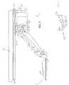
- FIG. 1is an exploded, perspective view of the auxiliary shelf mechanism of the invention.
- FIG. 2is a side elevational view of the auxiliary shelf mechanism in its downward and retracted position. Those parts of the mechanism which would not ordinarily be seen from this angle are shown in dotted lines; a keyboard is also shown in dotted lines, but does not form part of the invention.
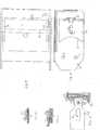
- FIG. 3is a top plan view of an adjustable stopping means for use in the auxiliary shelf mechanism of the invention.
- FIG. 4is a side elevational view, similar to the view in FIG. 2, showing the auxiliary shelf mechanism in an extended and upward position.
- FIG. 5is a top plan view showing the auxiliary shelf mechanism as attached to a desk.
- the dotted linesshow how the auxiliary shelf mechanism may be rotated relative to the desk, which is also shown in dotted lines.
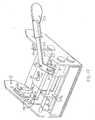
- FIG. 6is a front elevational view of the auxiliary shelf mechanism, showing the means by which the mechanism can be made to rotate as shown in FIG. 4.
- FIG. 7is a side elevational view of a portion of a different embodiment of the invention, showing a movable stopping means. The dotted lines show the stopping means in a different position.
- FIG. 8is a side elevational view of the portion of the invention shown in FIG. 7, showing slightly different details of the movable stopping means.
- FIG. 9is a top view of an embodiment of the invention, showing a movable stopping means.
- FIG. 10is a top view cf a portion of an embodiment of the invention, showing a stopping means with a chamfer in combination with a section of the mounting bracket.
- FIG. 11shows the same view as shown in FIG. 10, with the stopping means with a chamfer and a portion of the mounting bracket, with the additional showing of the side arm.
- FIG. 12shows a side view of an alternate embodiment of the side arm in combination with the stopping means.
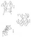
- FIG. 13is a bottom elevational view of a different movable stopping means.
- FIG. 14is a bottom view of the embodiment shown in FIG. 13.
- FIG. 15is a top elevational view of element of the mechanism used to allow the stopping means to move as shown in FIG. 13.
- FIG. 16is a top elevational view of a different element of the mechanism used to allow the stopping means to move as shown in FIG. 13.
- FIG. 17is a bottom elevational view of a different movable stopping means.
- FIG. 18is a bottom view of the embodiment shown in FIG. 17.
- FIG. 19is a top elevational view of an element of the mechanism used to allow the stopping means to move as shown in FIG. 17.
- the term “desk”means any desk, table, shelf, or other suitable work surface.
- the term “desk top”means the working surface of a desk (i.e. the surface facing upwards).
- the term “front” when applied to any component of the auxiliary shelf mechanismmeans the end closest to the user; the term “back” means the part farthest away from the user.
- Auxiliary shelf mechanism 1includes an upper arm 2 , a mounting bracket 3 , a shelf bracket 4 , and a pair of side arms 5 . Though two side arms 5 are shown in FIG. 1 and constitute the preferred embodiment, only one side arm is required. Attached to mounting bracket 3 is a mounting bracket support 6 (shown in FIG. 6) in combination with swivel bracket 32 and swivel bracket support 33 . The combination of the swivel bracket 33 and the mounting bracket support is illustrated in further detail in FIG. 6.
- a first pivot rod 7connects mounting bracket 3 to upper arm 2 at paired pivot points 8 , secured by washers 9 and push nuts 10 .
- Upper arm 2is attached to shelf bracket 4 by means of second pivot rod 11 through holes 12 (one such hole is not shown).
- Side arms 5are attached to shelf bracket 4 by means of third pivot rod 13 .
- the use of two side arms 5is preferred and illustrated because this arrangement enhances stability of shelf bracket 4 , but only one is necessary.
- Side arms 5are attached to mounting bracket 3 by means of bolt 14 , which extends through holes 15 in the mounting bracket 3 (one not shown) and through first openings 16 in the side arms.
- Spacer 41is wrapped around bolt 14 and is wider than first openings 16 , so as to prevent it from sliding out from between side arms 5 via first openings 16 . Spacer 41 provides assistance in locking the mechanism in place, as described more fully below.
- One end of bolt 14is square (this end is not shown in drawing). The square end can either be part of bolt 14 as manufactured or can be a cover which is slipped onto the round end. The square end prevents bolt 14 from rotating due to the interaction of the square end with first opening 16 .
- each side arm 5projects behind first openings 16 away from shelf bracket 4 .
- Lower arm 17is not required, but is included in the preferred embodiments shown in the drawings.
- Lower arm 17is attached to upper arm 2 by means of fourth pivot rod 18 through holes 19 (one not shown) in upper arm 2 .
- Lower arm 17is also attached to both side arms 5 and mounting bracket 3 by means of bolt 14 .
- Bolt 14passes through lower arm 17 through second openings 20 (one not shown).
- auxiliary shelf mechanism 1may be attached to the underside of a desk top 36 by means of mounting track 22 .
- Mounting track 22is affixed to the underside of desk top 36 by conventional means, such as nails or screws.
- Swivel bracket support 33cooperates with mounting track 22 as is more fully shown in FIG. 6 to permit auxiliary shelf mechanism 1 to slide back and forth relative to mounting track 22 .
- stopping means 23which is attached to mounting bracket 3 . Stopping means 23 has a first side 24 which faces towards the curved end 21 of the side arm. There is one first side 24 for each side arm 5 . Preferably, though not necessarily, first side 24 is concave in shape, as shown in the different figures.
- the two first sides 24can form part of a single stopping means, which consequently has a C-shaped top profile, as shown in FIG. 3 (the first sides 24 representing the ends of the short parts of the "C” 37 ), with the open side of the "C" facing towards the front.
- the center piece 38 connecting the two sides of the stopping means 23can have its lateral position relative to mounting bracket 3 adjusted by means of knob 27 , as described more fully below, or by any other means.
- two stopping means 23may be used, each of which may be attached in a fixed manner by spot-welding or flat riveting (or other conventional means) to the side of mounting bracket 3 .
- Keyboard 25can rest directly on shelf bracket 4 , as shown in the drawing.
- an additional, wider keyboard shelf(not shown) is attached to shelf bracket 4 through attachment holes 26 (as shown in FIG. 1), on which can rest the keyboard.
- Additional componentssuch as a supplemental shelf for a computer mouse or pad of paper may be attached to the keyboard shelf (or directly to shelf bracket 4 ).
- upper arm 2 , lower arm 17 , and mounting bracket 3thereby form a wedge-shaped box whose surfaces are made up of the top of upper arm 2 , the base of lower arm 17 , and the overlapping sides of upper arm 2 and lower arms 17 , and whose edges are defined by first pivot rod 7, fourth pivot rod 18 , and bolt 14 .
- the systemresembles a triangle, which can be pivoted to permit the raising or lowering of shelf bracket 4 relative to mounting bracket 3 , and hence the top of the desk 36 .
- first pivot rod 7As upper arm 2 pivots about first pivot rod 7 , lower arm 17 both pivots about bolt 14 and slides forward or backward relative to it, via first and second openings 16 and 20 .
- Curved ends 21 of side arms 5contact first sides 24 of stopping means 23 . This prevents side arms 5 from sliding rearwards, relative to bolt 14 , past the point where side arms 5 contact the first sides 24 of the stopping means 23 . When first sides 24 have a concave shape, this point varies as side arms 5 are pivoted around bolt 14 .
- stopping means 23By positioning stopping means 23 at a specific distance behind bolt 14 , and giving first sides 24 of stopping means 23 a particular degree of curvature (which may be easily determined by one of ordinary skill in the art), shelf bracket 4 can be kept at consistent angle relative to the ground, regardless of the height of shelf bracket 4 relative to mounting bracket 3 .
- FIGS. 2 and 4depict auxiliary shelf mechanism 1 in a retracted, downward position and in an extended, forward position respectively.
- auxiliary shelf mechanism 1It is preferable to upwardly bias auxiliary shelf mechanism 1 slightly, by means of a torsion spring 39 , or other types of springs (e.g. leaf springs) or other conventional mechanisms, such as a compressible fluid cylinder.
- a torsion spring 39or other types of springs (e.g. leaf springs) or other conventional mechanisms, such as a compressible fluid cylinder.
- Stopping means 23can be fixed in position during the manufacturing process by any conventional means. Among the means for fixing it are spot welding or flat riveting. Fixing the stopping means in position ensures that the horizontal orientation of shelf bracket 4 remains constant.
- the position of stopping means 23can be adjustable. By adjusting the position of the stopping means, the angle of shelf bracket 4 relative to the ground can be changed. This is because a change in position of stopping means 23 changes the amount by which the side arms 5 can be pushed back, which in turn changes the angle of shelf bracket 4 to the ground.
- the position of stopping means 23can only be adjusted within certain parameters, the limits of which ensure that the angle of shelf bracket 4 is always within an ergonomically acceptable range.
- stopping means 23is movable, its position may be adjusted by a variety of means, such as with a sliding track with a locking mechanism, or with a rack and pinion mechanism, or with a pneumatic cylinder.
- One preferred meansis by way of a screw-type mechanism, as shown in FIGS. 7-9.
- Knob 27is connected by threaded bolt 28 to stopping means 23 .
- Threaded bolt 28is attached to stopping means 23 by being screwed into threaded aperture 29 in stopping means 23 .
- FIG. 9shows a top view of the mechanism. As may be seen from the drawing, stop rod 42 runs parallel to center piece 38 of stopping means 23 .
- Stop rod 42is fixed in place and is vertically positioned in the middle of ends 37 of stopping means 23 , running through ends 37 via third openings 43 (only one shown). As stopping means 23 moves back and forth relative to mounting bracket 3 from the turning of knob 27 , third openings 43 move relative to stop rod 42 . Once stop rod 42 reaches an end of third openings 43 , stopping means 23 cannot move any further in that direction.
- the dotted lines in FIG. 7show stopping means 23 in a forwardly displaced position compared to the position shown in the solid lines.
- FIGS. 13-16Another screw-type mechanism for adjusting the position of the stopping means is shown in FIGS. 13-16.
- sliding bracket 46is adjacent to mounting bracket 3 .
- Sliding bracket 46is shown in more detail in FIG. 15.
- Stopping means 23are attached to sliding bracket 46 by conventional means, such as rivets or screws.
- Sliding bracket 46has, near to where stopping means 23 are attached to it, fourth openings 53 , through which passes stop rod 42 , which is attached to mounting bracket 3 .
- the interaction between stop rod 42 and fourth openings 53limits the amount of possible back and forth movement by the mechanism.
- Sliding bracket 46is attached to setting bracket 47 (shown in more detail in FIG. 16) by means of attachment pin 48 which passes through opening 49 in setting bracket 47 and openings 63 in sliding bracket 46 (shown in FIG. 15) .
- Setting bracket 49is attached to mounting bracket 3 by means of attachment rods 50 and 51 , which pass through holes 52 (see FIG. 16). Opening 49 is angled so that as setting bracket 47 is moved from side to side relative to mounting bracket 3, attachment pin 48 , which must slide within the confines of opening 49 is forced to move either forward or backward, which in turn forces sliding bracket 46 and stopping means 23 to also move forward or backward.
- the lateral position of setting bracket 47is adjusted by means of knob 54 in combination with threaded attachment rod 50 and threaded fastener 55 .
- Threaded fastener 55is attached to setting bracket 46 adjacent to one of the holes 52 .
- Threaded attachment rod 50passes through one hole 52 and threaded fastener 55 .
- One end of threaded attachment rod 50is attached to knob 54 (which is positioned on the outside of mounting bracket 3 ), while the other is rotatably fixed to the opposite side of mounting bracket 3 .
- knob 54When knob 54 is turned by the user, it turns threaded attachment rod 50 and causes it to interact with threaded fastener 55 .
- threaded attachment rod 50is rotatably fixed, threaded fastener 55 is forced to "migrate” up and down threaded attachment rod 50 , causing setting bracket 46 to move laterally, and the rest of the mechanism to move forwards and backwards as described above.
- FIGS. 17-19A related mechanism for adjusting the position of the stopping means 23 is shown in FIGS. 17-19.
- the position of the stopping means 23is adjusted by means of sliding bracket 46 in combination with setting bracket 47a .
- the lateral position of setting bracket 47ais not adjusted by means of threaded screw mechanism as described above, but rather by means of adjustment lever 56 .
- Setting bracket 47adiffers from setting bracket 47 in that it includes a laterally protruding wing 59 , which has within it a hole 60 .
- Position bracket 57is fixedly attached to mounting bracket 3 .
- Adjustment lever 56is pivotally attached to position bracket 57 by pin 58 .
- Adjustment lever 56is attached to setting bracket 47 a by means of pin 61 which passes through hole 60 in setting bracket 47a and through slot 62 in adjustment lever 56 .
- adjustment lever 56pivots around pin 58 . This in turn forces movement of slot 62 relative to mounting bracket 3 . Because of the attachment of setting bracket 47a to adjustment lever 56 by means of pin 61 through slot 62 , movement of slot 62 forces lateral movement of setting bracket 47a along attachment rods 51 . As discussed above, this in turn provides forward and backwards movement of stopping means 23 .
- the stopping meanscan be easier or more difficult for the user.
- the stopping meanscan only be adjusted using a screwdriver (instead of by the mechanisms described above) it will less convenient to adjust. This arrangement may be desirable for some applications, where it is sought to minimize the number of adjustments which can be made by the immediate user.
- the primary purpose behind adjusting the stopping meansis to adjust the angle of keyboard shelf 4 relative to the ground.
- An alternative means for adjusting the horizontal orientation of shelf bracket 4 which is particularly useful when stopping means 23 is not adjustableis by means of conventional locking knob 31 , as shown in FIG. 1.
- Bolt 14is screwed into locking knob 31 .
- Bolt 14is screwed into locking knob 31 .
- Bolt 14is prevented from also turning by the interaction of its square end with lateral opening 16 .
- the threaded connection between locking knob 31 and bolt 14forces locking knob 31 to move in towards spacer 41 , forcing side arm 5 and lower arm 17 into closer contact with spacer 41 .
- the angle of shelf bracket 4can be adjusted by tilting the front of shelf bracket 4 up, pulling side arm 5 away from stopping means 23 and locking shelf bracket 4 into this position by tightening locking knob 31 .
- the angle of shelf bracket 4can be altered from what would permitted by the use of stopping means 23 .
- the use of locking knob 31is preferred when only one side arm 5 and one stopping means 23 are used, and when stopping means 23 cannot be moved. Locking knob 31 can also be used in conjunction with a movable stopping means.
- the height at which shelf bracket 4 is maintained during use or storage relative to desktop 36is controlled by the interaction of side arms 5 and stopping means 23 .
- Each side arm 5contacts the first side 24 of stopping means 23 , stopping the rearward motion of the side arms 5 and keeping the shelf bracket 4 at a constant angle relative to the ground.
- each side arm 5is pulled away from its respective stopping means 23 , permitting vertical movement of the auxiliary shelf mechanism 1 .
- each side arm 5once again contacts its respective stopping means 23 .
- the curved end 21 of each side arm 5does not slide relative to its respective stopping means 23 because of friction. Placing additional weight on shelf bracket 4 simply causes the curved ends 21 of the side arms 5 to "dig" into each stopping means 23 even more, further inhibiting vertical movement of auxiliary shelf mechanism 1 .
- first face 24 of stopping means 23is concave and has a 45° chamfer directed towards the outside of the mechanism (i.e. towards the mounting bracket).
- angle of the chamfercan be varied. This is shown in more detail in FIG. 10. This chamfer "funnels" the side arm into a comer created by the stopping means and the mounting bracket, as shown in FIG. 11. The increased amount of friction resulting from this arrangement results in greater vertical stability for auxiliary shelf mechanism 1 .
- An alternative means for improving the vertical stability of auxiliary shelf mechanism 1involves providing curved ends 21 of side arms 5 with a series of "teeth” which can cooperate with a complementary series of "teeth” on the first side 24 of stopping means 23 .
- the interaction of the teeth on curved end 21 and the first side 24can prevent vertical movement of auxiliary shelf mechanism 1 .
- a further alternative, shown in FIG. 12is to attach a pivoted side-arm cam 45 to curved end 21 of side arm 5 by means of pin 44 .
- the curvature of pivoted side-arm cam 45complements that of first side 24 , thus maximizing the contact area between the surfaces and the amount of friction between them, resulting in greater vertical stability for auxiliary shelf mechanism 1 .
- any of the foregoing methods for vertically stabilizing auxiliary shelf mechanism 1may be used in combination with any of the others (e.g. teeth may be placed on pivoted side-arm cam 45 , and curved face 24 of stopping means 23 ).
- auxiliary shelf mechanism 1Regardless of what system (if any), is used to stabilize the vertical positioning of auxiliary shelf mechanism 1 , the use of the stopping means/side arm mechanism permits the user to adjust the height of the keyboard in a facile, intuitive manner, without the need to reach awkwardly around the keyboard and fumble for levers or knobs. Moreover, this system is also mechanically quite simple, does not require the complex locking mechanisms of prior art devices, and presents a significant improvement over those devices.
- FIG. 6shows the means by which lateral movement of auxiliary shelf mechanism 1 is achieved.
- Mounting track 22is attached to the underside of desktop 36 , normally so that it is perpendicular to the front edge of desktop 36 .
- the outside edges of mounting track 22are configured so as to form a pair of inwardly facing, C-shaped brackets 34 .
- Swivel bracket 32is shaped so that it will fit into the C-shaped brackets 34 .
- Swivel bracket 32 (and the rest of auxiliary shelf mechanism 1 )can be moved by simply pushing the mechanism back and forth along the track. Unwanted lateral movement of auxiliary shelf mechanism 1 is controlled by friction between swivel bracket 32 and C-shaped brackets 34 .
- auxiliary shelf mechanism 1when weight is placed on shelf bracket 4 (for example when a keyboard and/or a pair of hands is resting on it), this will have a tendency to cause swivel bracket 32 to tilt forward, causing the rear of swivel bracket 32 to contact the top of C-shaped brackets 34 , increasing the friction-based resistance of auxiliary shelf mechanism 1 to lateral movement.
- an additional locking mechanismmay be provided to prevent lateral movement, but such a mechanism is generally unnecessary and makes adjustment of the position of auxiliary shelf mechanism 1 more cumbersome.
- Mechanical stops(not shown) may be employed at either end of C-shaped brackets 34 to ensure that auxiliary shelf mechanism 1 does not slide off mounting track 22 and fall to the floor.
- T-shaped brackets 34downward facing T-shaped tracks may be used in conjunction with compatible structures on the mounting bracket, such as is set forth in U.S. Patent No. 4,644,875.
- Other known means for mounting auxiliary shelf mechanism 1 to the underside of the deskcan also be used.
- Swivel bracket 32is attached to swivel bracket assembly 33 , mounting bracket 3 , and mounting bracket support 6 by means of a rivet (not shown).
- a large washer 35is fitted between swivel bracket 32 and mounting bracket 3 .
- the washermay be made of any number of hard and slippery materials, including metals, but is preferably made of a hard plastic such as polyethylene, and most preferably made of nylon.
- Mounting bracket support 6is attached to the inside of mounting bracket 3 . Generally, that attachment will be fixed (for example by spot welding or flat rivets). Therefore, when lateral force is exerted against auxiliary shelf mechanism 1 , mounting bracket 3 will tend to rotate around the rivet relative to swivel bracket 32 , which is prevented from rotating by the C-shaped brackets 34 of mounting track 22 . Thus, auxiliary shelf mechanism 1 can be rotated relative to the mounting track 22 and the desk top, as shown in FIG. 4.
- the rotational mechanism described hereinis known in the art, and other known mechanisms may also be used.
- auxiliary shelf mechanism 1can be varied, but will be a stiff material for most components, preferably steel or another metal or metal alloy.
- curved ends 21 of side arms 5 and first sides 24 of stopping means 23will have surfaces which are rough enough so as to limit their ability to slide past one another, locking the system in place as described above and enhancing its vertical stability.
- shelf bracketis the part of the auxiliary shelf mechanism 1 which is closest to the ground.
- U.S. Patent Nos. 5,257,767 and 4,616,798, described aboveThus, when the keyboard is pushed beneath the desk, the amount of leg room is maximized. This is achieved by attaching the various arms connecting mounting bracket 3 to shelf bracket 4 to the top and side of shelf bracket 4 .
- auxiliary shelfor keyboard shelf
- the attachment between the auxiliary shelf and the deskcan be made by either a parallelogram linkage, or by a non-parallelogram linkage, or by a linkage of the type described in detail in this application (i.e. upper arm-side arm-stopping means).
- auxiliary shelfwith a vertically oriented piece attached to its rear side.
- the linkagecan be attached to this vertically oriented piece, precluding the need for anything to project beneath the auxiliary shelf.
- shelfbracket 4is shaped in such a way that a more conventional parallelogram linkage or non-parallelogram linkage could be used, instead of the upper arm-side arm-stopping means system shown specifically in the drawings.
- Other attachment meansmay also be used, as will be readily apparent to those of skill in this area.
Landscapes
- Tables And Desks Characterized By Structural Shape (AREA)
- Input From Keyboards Or The Like (AREA)
- Clamps And Clips (AREA)
- Furniture Connections (AREA)
- Casings For Electric Apparatus (AREA)
- Accommodation For Nursing Or Treatment Tables (AREA)
- Push-Button Switches (AREA)
Abstract
Description
This application is a continuation-in-part of Provisional U.S. Application Serial No. 60/040,972, filed March 12, 1997 in the name of the same inventors and bearing the same title.
This invention relates to improved adjustable support mechanisms forkeyboards and other items.
The use of computers for both personal and business use has become socommon that it is fair to say that almost all businesses, and many homes, have at least onecomputer or computer terminal. Computers are particularly prevalent in the officeenvironment. Among the health issues which have become increasingly important as theuse of computers has become more common is the need to promote proper posture whileusing the computer so as to both maintain working efficiency and minimize theoccurrence of repetitive stress injuries. One basic principal which has been developed toaddress these issues is that the computer keyboard should be used while at a levelconsiderably below the level of most desktops, so the user's wrists, when the keyboard isin use, are a "neutral" position; that is, the surface defined by the user's forearms and the top of his or her hands is flat. In addition to regulating the height at which the keyboardis used, it is also important for ergonomic purposes to control the angle which thekeyboard shelf makes with the ground.
There have been a number of devices which have been developed for usein supporting keyboards (and associated computer accessories, such as a computermouse) at a level below the surface of a desk while in use and underneath the desk whennot in use. One such device is described in Smeenge, et al., U.S. Patent No. 4,616,798,which discloses the use of a parallelogram linkage to connect a shelf for holding akeyboard to the underside of the desk surface. The overall system described by Smeengepermits a fair degree of flexibility in positioning the keyboard relative to the user and thedesk. One disadvantage of Smeenge's system is that the parallelogram linkage used bythe system is attached to the underside of the keyboard support shelf. Therefore, whenthe keyboard is positioned underneath the desk, the leg room available to the userbetween the bottom of the mechanism and the floor is limited.
McConnell, U.S. Patent No. 5,257,767 attempted to address thisdeficiency of the Smeenge mechanism by using a non-parallelogram linkage to connectthe keyboard shelf to the underside of the desk. This non-parallelogram linkage causesthe front of the keyboard shelf to be angled upwards when the shelf is lowered relative tothe desk top, marginally increasing the leg room available to the user when the keyboardis positioned beneath the desk. Like the Smeenge mechanism, the McConnellmechanism has its linkage attached to the bottom of the keyboard shelf, which limits thetotal leg room available to the user.
In one aspect, this invention improves upon the prior art mechanisms bythe use of a novel linkage between the underside of the desk and the keyboard shelf,which novel linkage increases the leg room available to the user. The improvedmechanism of this invention permits the adjustment of the angle of the keyboard shelfrelative to the ground within certain parameters so that the angle is ergonomically correctfor the vast majority of users.
The mechanism according to this aspect of the invention comprises anovel articulating arm mechanism for permitting vertical movement of the keyboardshelf. The articulating arm mechanism has six major components: (1) a mountingbracket, (2) a mounting bracket support in combination with a swivel bracket, (3) a shelfbracket, (4) an upper arm, (5) at least one side arm, and (6) at least one stopping means.The upper arm links the shelf bracket and the mounting bracket; the side arm and thestopping means cooperate to keep the shelf bracket at a constant angle relative to theground.
A second aspect of the invention comprises the attachment of a linkagebetween a desk and a keyboard shelf so that nothing extends beneath the bottom of thekeyboard shelf.
FIG. 1 is an exploded, perspective view of the auxiliary shelf mechanismof the invention.
FIG. 2 is a side elevational view of the auxiliary shelf mechanism in itsdownward and retracted position. Those parts of the mechanism which would notordinarily be seen from this angle are shown in dotted lines; a keyboard is also shown indotted lines, but does not form part of the invention.
FIG. 3 is a top plan view of an adjustable stopping means for use in theauxiliary shelf mechanism of the invention.
FIG. 4 is a side elevational view, similar to the view in FIG. 2, showingthe auxiliary shelf mechanism in an extended and upward position.
FIG. 5 is a top plan view showing the auxiliary shelf mechanism asattached to a desk. The dotted lines show how the auxiliary shelf mechanism may berotated relative to the desk, which is also shown in dotted lines.
FIG. 6 is a front elevational view of the auxiliary shelf mechanism,showing the means by which the mechanism can be made to rotate as shown in FIG. 4.
FIG. 7 is a side elevational view of a portion of a different embodiment ofthe invention, showing a movable stopping means. The dotted lines show the stoppingmeans in a different position.
FIG. 8 is a side elevational view of the portion of the invention shown inFIG. 7, showing slightly different details of the movable stopping means.
FIG. 9 is a top view of an embodiment of the invention, showing amovable stopping means.
FIG. 10 is a top view cf a portion of an embodiment of the invention,showing a stopping means with a chamfer in combination with a section of the mountingbracket.
FIG. 11 shows the same view as shown in FIG. 10, with the stoppingmeans with a chamfer and a portion of the mounting bracket, with the additional showingof the side arm.
FIG. 12 shows a side view of an alternate embodiment of the side arm incombination with the stopping means.
FIG. 13 is a bottom elevational view of a different movable stoppingmeans.
FIG. 14 is a bottom view of the embodiment shown in FIG. 13.
FIG. 15 is a top elevational view of element of the mechanism used toallow the stopping means to move as shown in FIG. 13.
FIG. 16 is a top elevational view of a different element of the mechanismused to allow the stopping means to move as shown in FIG. 13.
FIG. 17 is a bottom elevational view of a different movable stoppingmeans.
FIG. 18 is a bottom view of the embodiment shown in FIG. 17.
FIG. 19 is a top elevational view of an element of the mechanism used toallow the stopping means to move as shown in FIG. 17.
As used in this specification and the appended claims, the term "desk"means any desk, table, shelf, or other suitable work surface. The term "desk top" meansthe working surface of a desk (i.e. the surface facing upwards). The term "front" when applied to any component of the auxiliary shelf mechanism means the end closest to theuser; the term "back" means the part farthest away from the user.
Referring to FIG. 1, there is illustrated an exploded view of anauxiliaryshelf mechanism 1 according to the invention.Auxiliary shelf mechanism 1 includes anupper arm2, amounting bracket 3, ashelf bracket 4, and a pair of side arms5. Thoughtwo side arms5 are shown in FIG. 1 and constitute the preferred embodiment, only oneside arm is required. Attached to mountingbracket 3 is a mounting bracket support6(shown in FIG. 6) in combination withswivel bracket 32 andswivel bracket support 33.The combination of theswivel bracket 33 and the mounting bracket support is illustratedin further detail in FIG. 6. A first pivot rod7 connectsmounting bracket 3 to upper arm2 at pairedpivot points 8, secured bywashers 9 and pushnuts 10. Upper arm2 isattached toshelf bracket 4 by means ofsecond pivot rod 11 through holes12 (one suchhole is not shown).
Side arms5 are attached toshelf bracket 4 by means ofthird pivot rod 13.The use of two side arms5 is preferred and illustrated because this arrangement enhancesstability ofshelf bracket 4, but only one is necessary. Side arms5 are attached tomountingbracket 3 by means ofbolt 14, which extends through holes15 in the mountingbracket3 (one not shown) and throughfirst openings 16 in the side arms. Spacer41 iswrapped aroundbolt 14 and is wider thanfirst openings 16, so as to prevent it fromsliding out from between side arms5 viafirst openings 16. Spacer41 provides assistancein locking the mechanism in place, as described more fully below. One end ofbolt 14 issquare (this end is not shown in drawing). The square end can either be part ofbolt 14 asmanufactured or can be a cover which is slipped onto the round end. The square end preventsbolt 14 from rotating due to the interaction of the square end withfirst opening 16.
Acurved end 21 of each side arm5 projects behindfirst openings 16 awayfromshelf bracket 4.Lower arm 17 is not required, but is included in the preferredembodiments shown in the drawings.Lower arm 17 is attached to upper arm2 by meansoffourth pivot rod 18 through holes19 (one not shown) in upper arm2.Lower arm 17 isalso attached to both side arms5 and mountingbracket 3 by means ofbolt 14.Bolt 14passes throughlower arm 17 through second openings20 (one not shown).
As shown in FIG. 2,auxiliary shelf mechanism 1 may be attached to theunderside of adesk top 36 by means of mountingtrack 22. Mountingtrack 22 is affixedto the underside ofdesk top 36 by conventional means, such as nails or screws.Swivelbracket support 33 cooperates with mountingtrack 22 as is more fully shown in FIG. 6 topermitauxiliary shelf mechanism 1 to slide back and forth relative to mountingtrack 22.Also shown in FIG. 2 is stoppingmeans 23, which is attached to mountingbracket 3.Stopping means23 has afirst side 24 which faces towards thecurved end 21 of the sidearm. There is onefirst side 24 for each side arm5. Preferably, though not necessarily,first side 24 is concave in shape, as shown in the different figures.
In an embodiment where the stopping means is adjustable and when twoside arms are used, the twofirst sides 24 can form part of a single stopping means, whichconsequently has a C-shaped top profile, as shown in FIG. 3 (thefirst sides 24representing the ends of the short parts of the "C"37), with the open side of the "C"facing towards the front. The center piece38 connecting the two sides of the stoppingmeans23 can have its lateral position relative to mountingbracket 3 adjusted by means ofknob 27, as described more fully below, or by any other means. When two side arms5are used, but stopping means23 is not adjustable, two stopping means may be used, eachof which may be attached in a fixed manner by spot-welding or flat riveting (or otherconventional means) to the side of mountingbracket 3.
Keyboard25 (not part of this invention) can rest directly onshelf bracket 4, as shown in the drawing. Preferably, however, an additional, wider keyboard shelf(not shown) is attached toshelf bracket 4 through attachment holes26 (as shown in FIG.1), on which can rest the keyboard. Additional components, such as a supplemental shelffor a computer mouse or pad of paper may be attached to the keyboard shelf (or directlyto shelf bracket4).
In the preferred embodiment, upper arm2,lower arm 17, and mountingbracket 3 thereby form a wedge-shaped box whose surfaces are made up of the top ofupper arm2, the base oflower arm 17, and the overlapping sides of upper arm2 andlower arms 17, and whose edges are defined by first pivot rod 7,fourth pivot rod 18, andbolt 14. From the side, as shown in FIG. 2, the system resembles a triangle, which can bepivoted to permit the raising or lowering ofshelf bracket 4 relative to mountingbracket 3,and hence the top of thedesk 36. As upper arm2 pivots about first pivot rod7,lowerarm 17 both pivots aboutbolt 14 and slides forward or backward relative to it, via firstandsecond openings
Curved ends21 of side arms5 contact first sides24 of stoppingmeans 23.This prevents side arms5 from sliding rearwards, relative to bolt14, past the point whereside arms5 contact thefirst sides 24 of the stoppingmeans 23. When first sides24 havea concave shape, this point varies as side arms5 are pivoted aroundbolt 14. By positioning stopping means23 at a specific distance behindbolt 14, and givingfirst sides 24 of stopping means23 a particular degree of curvature (which may be easilydetermined by one of ordinary skill in the art),shelf bracket 4 can be kept at consistentangle relative to the ground, regardless of the height ofshelf bracket 4 relative tomountingbracket 3.
Side arms5 are kept in contact with thefirst sides 23 of stoppingmeans 24by means of the arrangement ofshelf bracket 4, upper arm2, and side arms5. Upper arm2 is pivotally connected toshelf bracket 4 by means ofsecond pivot rod 11. Therefore,the weight of shelf bracket4 (plus the weight of anything else attached to it or resting onit) will tend to forceshelf bracket 4 to pivot aroundfirst pivot rod 11. This pivotingaction forcesthird pivot rod 13 backwards, in turn forcing side arm5 (attached toshelfbracket 4 by means of third pivot rod13) back into thefirst sides 24 of stoppingmeans 23. Thus, side arms5 will always be in contact with stoppingmeans 23, keepingshelfbracket 4 at a consistent horizontal orientation.
The relative movements of the various components of the mechanism asshelf bracket 4 is moved in a vertical direction can best be appreciated by comparing theirpositions as shown in FIGS. 2 and 4, which depictauxiliary shelf mechanism 1 in aretracted, downward position and in an extended, forward position respectively.
It is preferable to upwardly biasauxiliary shelf mechanism 1 slightly, bymeans of a torsion spring39, or other types of springs (e.g. leaf springs) or otherconventional mechanisms, such as a compressible fluid cylinder.
Stopping means23 can be fixed in position during the manufacturingprocess by any conventional means. Among the means for fixing it are spot welding or flat riveting. Fixing the stopping means in position ensures that the horizontal orientationofshelf bracket 4 remains constant.
Alternatively, the position of stoppingmeans 23 can be adjustable. Byadjusting the position of the stopping means, the angle ofshelf bracket 4 relative to theground can be changed. This is because a change in position of stopping means23changes the amount by which the side arms5 can be pushed back, which in turn changesthe angle ofshelf bracket 4 to the ground. Preferably the position of stoppingmeans 23can only be adjusted within certain parameters, the limits of which ensure that the angleofshelf bracket 4 is always within an ergonomically acceptable range.
If stopping means23 is movable, its position may be adjusted by a varietyof means, such as with a sliding track with a locking mechanism, or with a rack andpinion mechanism, or with a pneumatic cylinder. One preferred means, however, is byway of a screw-type mechanism, as shown in FIGS. 7-9.Knob 27 is connected bythreaded bolt28 to stoppingmeans 23. Threaded bolt28 is attached to stoppingmeans 23 by being screwed into threadedaperture 29 in stoppingmeans 23. Asknob 27 isturned in one direction, threaded bolt28 is also turned; because stopping means23 andthreadedaperture 29 cannot also turn (because of geometric constraints within mountingbracket3), the turning of threaded bolt28 in one direction forces it to unscrew fromthreadedaperture 29, pushing stopping means23 towards the front of mountingbracket 3. The turning ofknob 27 in the other direction has the opposite effect. The degree towhich threaded bolt28 can be screwed or unscrewed from the threaded aperture29 (andhence the degree to which stopping means23 may be moved) may be governed by theuse of mechanical stopping means as shown in FIGS. 8 and 9. FIG. 9 shows a top view of the mechanism. As may be seen from the drawing, stoprod 42 runs parallel to centerpiece38 of stoppingmeans 23. FIG. 8 shows a side view of mountingbracket 3 withstoppingmeans 23. Stoprod 42 is fixed in place and is vertically positioned in themiddle of ends37 of stoppingmeans 23, running throughends 37 via third openings43(only one shown). As stopping means23 moves back and forth relative to mountingbracket 3 from the turning ofknob 27,third openings 43 move relative to stoprod 42.Oncestop rod 42 reaches an end ofthird openings 43, stopping means23 cannot moveany further in that direction. The dotted lines in FIG. 7 show stopping means23 in aforwardly displaced position compared to the position shown in the solid lines.
Other simple mechanical means may also be used to limit the amount bywhich stopping means23 can be moved.
Another screw-type mechanism for adjusting the position of the stoppingmeans is shown in FIGS. 13-16. As shown in FIG. 13, slidingbracket 46 is adjacent tomountingbracket 3. Slidingbracket 46 is shown in more detail in FIG. 15. Stoppingmeans23 are attached to slidingbracket 46 by conventional means, such as rivets orscrews. Slidingbracket 46 has, near to where stopping means23 are attached to it, fourthopenings53, through which passes stoprod 42, which is attached to mountingbracket 3.As was discussed above in connection with FIGS. 7 and 8, the interaction betweenstoprod 42 and fourth openings53 limits the amount of possible back and forth movement bythe mechanism.
Slidingbracket 46 is attached to setting bracket47 (shown in more detailin FIG. 16) by means ofattachment pin 48 which passes through opening49 in settingbracket 47 andopenings 63 in sliding bracket46 (shown in FIG. 15) . Settingbracket 49 is attached to mountingbracket 3 by means ofattachment rods 50 and51, which passthrough holes52 (see FIG. 16).Opening 49 is angled so that as settingbracket 47 ismoved from side to side relative to mountingbracket 3,attachment pin 48, which mustslide within the confines of opening49 is forced to move either forward or backward,which in turnforces sliding bracket 46 and stopping means23 to also move forward orbackward.
For example, looking at FIG. 14, if settingbracket 47 is pushed to the left,it is easy to see thatattachment pin 48 will be forced along opening49 towards the frontof mountingbracket 3, forcing slidingbracket 46 to also move forward, carrying stoppingmeans23 forward also. By varying the angle of opening49 it is possible to control howmuch sideways movement of settingbracket 47 will force forward movement of slidingbracket 46.
In the embodiment shown in FIGS. 13 and 14, the lateral position ofsetting bracket47 (and hence slidingbracket 46 and stopping means23) is adjusted bymeans ofknob 54 in combination with threaded attachment rod50 and threaded fastener55. Threaded fastener55 is attached to settingbracket 46 adjacent to one of theholes 52.Threaded attachment rod50 passes through onehole 52 and threaded fastener55. Oneend of threaded attachment rod50 is attached to knob54 (which is positioned on theoutside of mounting bracket3), while the other is rotatably fixed to the opposite side ofmountingbracket 3. Whenknob 54 is turned by the user, it turns threaded attachment rod50 and causes it to interact with threaded fastener55. Because threaded attachment rod50 is rotatably fixed, threaded fastener55 is forced to "migrate" up and down threaded attachment rod50, causing settingbracket 46 to move laterally, and the rest of themechanism to move forwards and backwards as described above.
A related mechanism for adjusting the position of the stopping means23 isshown in FIGS. 17-19. In this embodiment, the position of the stopping means23 isadjusted by means of slidingbracket 46 in combination with setting bracket47a.However, the lateral position of setting bracket47a is not adjusted by means of threadedscrew mechanism as described above, but rather by means ofadjustment lever 56.Setting bracket47a differs from settingbracket 47 in that it includes a laterallyprotruding wing59, which has within it a hole60.Position bracket 57 is fixedly attachedto mountingbracket 3.Adjustment lever 56 is pivotally attached to positionbracket 57bypin 58.Adjustment lever 56 is attached to setting bracket47a by means ofpin 61which passes through hole60 in setting bracket47a and throughslot 62 inadjustmentlever 56.
When thehandle 63 ofadjustment lever 56 is moved by the user,adjustment lever 56 pivots aroundpin 58. This in turn forces movement ofslot 62relative to mountingbracket 3. Because of the attachment of setting bracket47a toadjustment lever 56 by means ofpin 61 throughslot 62, movement ofslot 62 forceslateral movement of setting bracket47a alongattachment rods 51. As discussed above,this in turn provides forward and backwards movement of stoppingmeans 23.
Depending upon the exact mechanism used to adjust the stopping means,such adjustment can be easier or more difficult for the user. For example, if the stoppingmeans can only be adjusted using a screwdriver (instead of by the mechanisms describedabove) it will less convenient to adjust. This arrangement may be desirable for some applications, where it is sought to minimize the number of adjustments which can bemade by the immediate user.
The primary purpose behind adjusting the stopping means is to adjust theangle ofkeyboard shelf 4 relative to the ground. The farther forward stopping means23is positioned, the greater the elevation of the front ofshelf bracket 4, and vice-versa. Analternative means for adjusting the horizontal orientation ofshelf bracket 4 which isparticularly useful when stopping means23 is not adjustable is by means ofconventionallocking knob 31, as shown in FIG. 1.Bolt 14 is screwed into lockingknob 31. Whenlockingknob 31 is turned,bolt 14 is prevented from also turning by the interaction of itssquare end withlateral opening 16. The threaded connection between lockingknob 31andbolt 14forces locking knob 31 to move in towards spacer41, forcing side arm5 andlower arm 17 into closer contact with spacer41. This eventually tightens the system tothe point where neither rotation or lateral movement oflower arm 17 or side arm5 aboutbolt 14 is possible. To facilitate the "squeezing" oflower arm 17, its rearward sectionsaround and adjacent toopenings 20 do not have a bottom section connecting them, unlikeat the its forward sections around and adjacent tofourth pivot rod 18.
When lockingknob 31 is used, the angle ofshelf bracket 4 can be adjustedby tilting the front ofshelf bracket 4 up, pulling side arm5 away from stoppingmeans 23andlocking shelf bracket 4 into this position by tightening lockingknob 31. By"locking" side arm5 at a position where it is pulled away from stoppingmeans 23, theangle ofshelf bracket 4 can be altered from what would permitted by the use of stoppingmeans 23. The use of lockingknob 31 is preferred when only one side arm5 and one stopping means23 are used, and when stopping means23 cannot be moved. Lockingknob 31 can also be used in conjunction with a movable stopping means.
Other similar, known friction-based systems, such as stopping means withhandles, can be used in place of lockingknob 31.
The height at whichshelf bracket 4 is maintained during use or storagerelative todesktop 36 is controlled by the interaction of side arms5 and stoppingmeans 23. Each side arm5 contacts thefirst side 24 of stoppingmeans 23, stopping therearward motion of the side arms5 and keeping theshelf bracket 4 at a constant anglerelative to the ground. By tilting the front ofshelf bracket 4 up, each side arm5 is pulledaway from its respective stopping means23, permitting vertical movement of theauxiliary shelf mechanism 1. When the front ofshelf bracket 4 is released, each side arm5 once again contacts its respective stopping means23. Thecurved end 21 of each sidearm5 does not slide relative to its respective stopping means23 because of friction.Placing additional weight onshelf bracket 4 simply causes the curved ends21 of the sidearms5 to "dig" into each stopping means23 even more, further inhibiting verticalmovement ofauxiliary shelf mechanism 1.
This friction based impediment to movement is enhanced by the use of apreferred configuration of stoppingmeans 23. In this preferred embodiment,first face 24of stoppingmeans 23 is concave and has a 45° chamfer directed towards the outside ofthe mechanism(i.e. towards the mounting bracket). (One of skill in the art will readilyappreciate that the angle of the chamfer can be varied.) This is shown in more detail inFIG. 10. This chamfer "funnels" the side arm into a comer created by the stopping meansand the mounting bracket, as shown in FIG. 11. The increased amount of friction resulting from this arrangement results in greater vertical stability forauxiliary shelfmechanism 1.
An alternative means for improving the vertical stability ofauxiliary shelfmechanism 1 involves providing curved ends21 of side arms5 with a series of "teeth"which can cooperate with a complementary series of "teeth" on thefirst side 24 ofstoppingmeans 23. The interaction of the teeth oncurved end 21 and thefirst side 24 canprevent vertical movement ofauxiliary shelf mechanism 1. A further alternative, shownin FIG. 12 is to attach a pivoted side-arm cam45 tocurved end 21 of side arm5 bymeans ofpin 44. The curvature of pivoted side-arm cam45 complements that offirstside 24, thus maximizing the contact area between the surfaces and the amount of frictionbetween them, resulting in greater vertical stability forauxiliary shelf mechanism 1.
Any of the foregoing methods for vertically stabilizingauxiliary shelfmechanism 1 may be used in combination with any of the others (e.g. teeth may be placedon pivoted side-arm cam45, andcurved face 24 of stopping means23).
Regardless of what system (if any), is used to stabilize the verticalpositioning ofauxiliary shelf mechanism 1, the use of the stopping means/side armmechanism permits the user to adjust the height of the keyboard in a facile, intuitivemanner, without the need to reach awkwardly around the keyboard and fumble for leversor knobs. Moreover, this system is also mechanically quite simple, does not require thecomplex locking mechanisms of prior art devices, and presents a significant improvementover those devices.
FIG. 6 shows the means by which lateral movement ofauxiliary shelfmechanism 1 is achieved. Mountingtrack 22 is attached to the underside ofdesktop 36, normally so that it is perpendicular to the front edge ofdesktop 36. The outside edges ofmountingtrack 22 are configured so as to form a pair of inwardly facing, C-shapedbrackets 34.Swivel bracket 32 is shaped so that it will fit into the C-shapedbrackets 34.Swivel bracket32 (and the rest of auxiliary shelf mechanism1) can be moved by simplypushing the mechanism back and forth along the track. Unwanted lateral movement ofauxiliary shelf mechanism 1 is controlled by friction betweenswivel bracket 32 and C-shapedbrackets 34. Moreover, when weight is placed on shelf bracket4 (for examplewhen a keyboard and/or a pair of hands is resting on it), this will have a tendency to causeswivel bracket 32 to tilt forward, causing the rear ofswivel bracket 32 to contact the topof C-shapedbrackets 34, increasing the friction-based resistance ofauxiliary shelfmechanism 1 to lateral movement. If desired, an additional locking mechanism may beprovided to prevent lateral movement, but such a mechanism is generally unnecessaryand makes adjustment of the position ofauxiliary shelf mechanism 1 more cumbersome.Mechanical stops (not shown) may be employed at either end of C-shapedbrackets 34 toensure thatauxiliary shelf mechanism 1 does not slide off mountingtrack 22 and fall tothe floor.
As an alternative to C-shapedbrackets 34, downward facing T-shapedtracks may be used in conjunction with compatible structures on the mounting bracket,such as is set forth in U.S. Patent No. 4,644,875. Other known means for mountingauxiliary shelf mechanism 1 to the underside of the desk can also be used.
The materials used in the construction ofauxiliary shelf mechanism 1 canbe varied, but will be a stiff material for most components, preferably steel or anothermetal or metal alloy. In a preferred embodiment, curved ends21 of side arms5 andfirstsides 24 of stoppingmeans 23 will have surfaces which are rough enough so as to limittheir ability to slide past one another, locking the system in place as described above andenhancing its vertical stability.
Another advantage of the present invention is that the shelf bracket is thepart of theauxiliary shelf mechanism 1 which is closest to the ground. Nothing projectsbelowshelfbracket 4 as in other prior art mechanisms, such as is shown in U.S. PatentNos. 5,257,767 and 4,616,798, described above. Thus, when the keyboard is pushedbeneath the desk, the amount of leg room is maximized. This is achieved by attachingthe various arms connecting mountingbracket 3 toshelf bracket 4 to the top and side ofshelf bracket 4.
The present inventors have found that by equipping the shelf bracket withan upwardly extending piece to permit attachment of link means, the vertical profile ofthe overall mechanism can be shortened, increasing the leg room available to the userwhen the keyboard is positioned beneath the desk. Thus, another aspect of the presentinvention is the attachment of an auxiliary shelf (or keyboard shelf) to a desk top, so thatthe auxiliary shelf can move both horizontally and vertically relative to the desk top, theattachment being made so that nothing extends below the bottom of the auxiliary shelf.This arrangement maximizes the amount of leg room beneath the auxiliary shelf. Theattachment between the auxiliary shelf and the desk can be made by either aparallelogram linkage, or by a non-parallelogram linkage, or by a linkage of the typedescribed in detail in this application (i.e. upper arm-side arm-stopping means).
One means by which this type of attachment may be accomplished is byusing an auxiliary shelf with a vertically oriented piece attached to its rear side. Thelinkage can be attached to this vertically oriented piece, precluding the need for anythingto project beneath the auxiliary shelf. For example,shelfbracket 4 is shaped in such away that a more conventional parallelogram linkage or non-parallelogram linkage couldbe used, instead of the upper arm-side arm-stopping means system shown specifically inthe drawings. Other attachment means may also be used, as will be readily apparent tothose of skill in this area.
Claims (60)
- An improved auxiliary shelf mechanism for vertically and horizontallypositioning an auxiliary shelf, including a means for attaching the auxiliary shelf to adesk so that the auxiliary shelf may be movably positioned relative to the desk, whereinthe improvement comprises:
an articulating arm mechanism comprising:wherein the side arm and the upper arm are not substantially parallel to each other.(a) a mounting bracket, the mounting bracket having a front end and a back end,the front end being closer to the front of the desk than the back end;(b) an upper arm pivotally connected to the mounting bracket at a first pivot point,the rear of the upper arm being defined as the end of the upper arm closest tothe mounting bracket;(c) a shelf bracket pivotally connected to the upper arm at a second pivot point;the front of the upper arm being defined as the end of the upper arm closest tothe shelf bracket;(d) a side arm pivotally connected to the shelf bracket at a third pivot point; theside arm being further attached to the mounting bracket at a fourth pivot point;the side arm having within it a first opening such that the side arm can bepivoted relative to the mounting bracket about the fourth pivot point and canbe reciprocatingly moved relative to the fourth pivot point; the front of theside arm being defined as the end closest to the third pivot point, and the rearof the side arm being defined as the end opposite from the front;(e) a stopping means, the stopping means having a first side facing towards therear of the side arm, such that when the side arm moves laterally relative to the fourth pivot point, the rear of the side arm can contact the first side of thestopping means; - The auxiliary shelf mechanism of claim 1, wherein the third pivot point isdisposed beneath the second pivot point.
- The auxiliary shelf mechanism of claim 1, wherein the fourth pivot point isdisposed beneath the first pivot point.
- The auxiliary shelf mechanism of claim 1, wherein the fourth pivot point isdisposed beneath the first pivot point, and the third pivot point is disposed beneath thesecond pivot point.
- The auxiliary shelf mechanism of claim 1, wherein the first side of the stoppingmeans is concave.
- The auxiliary shelf mechanism of claim 1, wherein the first and fourth pivotpoints are closer together than the second and third pivot points.
- The auxiliary shelf mechanism of claim 1, wherein the fourth pivot point isdisposed beneath the first pivot point, and the third pivot point is disposed beneath thesecond pivot point, and the first side of the stopping means is concave.
- The auxiliary shelf mechanism of claim 1, wherein the articulating armmechanism further comprises a lower arm, the lower arm being pivotally attached to theupper arm at a fifth pivot point, the fifth pivot point being disposed between the first andsecond pivot points, the lower arm being further attached to the mounting bracket at thefourth pivot point, the lower arm further having within it a second opening, such that thelower arm can pivot about the fourth pivot point and can be reciprocatingly movedrelative to the fourth pivot point.
- The auxiliary shelf mechanism of claim 1, wherein the articulating armmechanism has two side arms and two stopping means, wherein the rear of each side armcan contact the first face of its corresponding stopping means.
- The auxiliary shelf mechanism of claim 9, wherein the two stopping means areconnected to each other.
- The auxiliary shelf mechanism of claim 1, wherein the position of the stoppingmeans is adjustable between a first position and a second position, the first position beingcloser to the front end of the mounting bracket than the second position, and the secondposition being closer to the back end of the mounting bracket than the first position.
- The auxiliary shelf mechanism of claim 11, wherein the position of the stoppingmeans can be fixed at either the first position, or the second position, or at any positionbetween the first and second positions.
- The auxiliary shelf mechanism of claim 6, wherein the position of the stoppingmeans is adjusted by means of threaded screw mechanism.
- The auxiliary shelf mechanism of claim 1, wherein the position of the stoppingmeans is adjusted by means of lever mechanism, the lever mechanism comprising anadjustment lever, a setting bracket, and a sliding bracket.
- The auxiliary shelf mechanism of claim 1, wherein the upper arm is connected tothe mounting bracket by a first pivot rod and to the shelf bracket by a second pivot rod,and further wherein the side arm is connected to the shelf bracket by a third pivot rod andto the mounting bracket by a bolt.
- The auxiliary shelf mechanism of claim 1, wherein the side arm may be fixed intoposition relative to the mounting bracket with a fixing means.
- The auxiliary shelf mechanism of claim 16, wherein the side arm may be fixedinto place with a locking mechanism.
- The auxiliary shelf mechanism of claim 17, wherein the locking means is alocking knob.
- The auxiliary shelf mechanism of claim 1, wherein the side arm is fixed intoposition by means of friction between the end of the side arm and the first face of thestopping means.
- The auxiliary shelf mechanism of claim 1, wherein the side arm is fixed intoposition by means of interaction between interconnecting projections on the end of theside arm and the first face of the stopping means.
- The auxiliary shelf mechanism of claim 1, wherein at least one stopping means isattached to an inside face of the mounting bracket, and further wherein the first face of atleast one stopping means is angled outwards towards the inside face of the mountingbracket to which the stopping means is attached.
- The auxiliary shelf mechanism of claim 1, wherein the rear end of the side armsand the first face of the stopping means comprise complementary series of interlockingteeth.
- The auxiliary shelf mechanism of claim 5, wherein the rear end of the side armconsists of a side-arm cam pivotally connected to the end of the side arm, the side-arm cam having a convex face which complements the concave face of the stopping meanswith which it comes in contact.
- The auxiliary shelf mechanism of claim 1, wherein the articulating armmechanism comprises means for rotating it relative to the desk.
- The auxiliary shelf mechanism of claim 24, wherein the means for rotating thearticulating arm mechanism relative to the desk comprises a swivel mechanism attachedto the mounting bracket in combination with a mounting track to which the mountingbracket is slidably connected, either directly or indirectly.
- The auxiliary shelf mechanism of claim 1, wherein:(a) there are two side arms;(b) there are two stopping means, optionally connected to one another;(c) the first face of each stopping means is concave;(d) each stopping means is attached to an inside face of the mounting bracket, andfurther wherein the first face of each stopping means is angled outwardstowards the inside face of the mounting bracket to which each stopping meansis attached so that the end of each side arm can contact a stopping means andan inside face of the mounting bracket simultaneously;(e) the fourth pivot point is disposed beneath the first pivot point, and the thirdpivot point is disposed beneath the second pivot point;(f) the articulating arm mechanism may be rotated relative to the desk by means ofa swivel mechanism attached to the mounting bracket in combination with amounting track to which the mounting bracket is slidably connected, eitherdirectly or indirectly.
- An articulating arm mechanism for connecting a shelf to a desk comprising:wherein the side arm and the upper arm are not parallel to each other.(a) a mounting bracket, the mounting bracket having a front end and a back end,the front end being closer to the front of the desk than the back end;(b) an upper arm pivotally connected to the mounting bracket at a first pivot point,the rear of the upper arm being defined as the end of the upper arm closest tothe mounting bracket;(c) a shelf bracket pivotally connected to the upper arm at a second pivot point;the front of the upper arm being defined as the end of the upper arm closest tothe shelf bracket;(d) a side arm pivotally connected to the shelf bracket at a third pivot point; theside arm being further attached to the mounting bracket at a fourth pivot point;the side arm having within it a first opening such that the side arm can bepivoted relative to the mounting bracket about the fourth pivot point and canbe reciprocatingly moved relative to the fourth pivot point; the front of theside arm being defined as the end closest to the third pivot point, and the rearof the side arm being defined as the end opposite from the front;(e) a stopping means, the stopping means having a first side facing towards therear of the side arm, such that when the side arm moves laterally relative to thefourth pivot point, the rear of the side arm can contact the first side of thestopping means;
- The articulating arm mechanism of claim 27, wherein the third pivot pointis disposed beneath the second pivot point.
- The articulating arm mechanism of claim 27, wherein the fourth pivotpoint is disposed beneath the first pivot point.
- The articulating arm mechanism of claim 27, wherein the fourth pivotpoint is disposed beneath the first pivot point, and the third pivot point is disposedbeneath the second pivot point.
- The articulating arm mechanism of claim 27, wherein the first side of thestopping means is concave.
- The articulating arm mechanism of claim 27, wherein the first and fourthpivot points are closer together than the second and third pivot points.
- The articulating arm mechanism of claim 27, wherein the fourth pivotpoint is disposed beneath the first pivot point, and the third pivot point is disposedbeneath the second pivot point, and the first side of the stopping means is concave.
- The articulating arm mechanism of claim 27, wherein the articulating armmechanism further comprises a lower arm, the lower arm being pivotally attached to theupper arm at a fifth pivot point, the fifth pivot point being disposed between the first andsecond pivot points, the lower arm being further attached to the mounting bracket at thefourth pivot point, the lower arm further having within it a second opening, such that thelower arm can pivot about the fourth pivot point and can be reciprocatingly movedrelative to the fourth pivot point.
- The articulating arm mechanism of claim 27, wherein the articulating armmechanism has two side arms and two stopping means, wherein the rear of each side armcan contact the first face of its corresponding stopping means.
- The articulating arm mechanism of claim 35, wherein the two stoppingmeans are connected to each other.
- The articulating arm mechanism of claim 36, wherein at least one of thefirst sides of each stopping means is concave.
- The articulating arm mechanism of claim 27, wherein the stopping meansis movable between a first position and a second position, the first position being closerto the front end of the mounting bracket than the back position, and the second positionbeing closer to the back end of the mounting bracket than the first position.
- The articulating arm mechanism of claim 38, wherein the position of thestopping means can be fixed at either the first position, or the second position, or at anyposition between the first and second positions.
- The articulating arm mechanism of claim 39, wherein the position of thestopping means is adjusted by means of a threaded screw mechanism.
- The articulating arm mechanism of claim 39, wherein the position of thestopping means is adjusted by means of a lever mechanism, the lever mechanismcomprising an adjustment lever, a setting bracket, and a sliding bracket.
- The articulating arm mechanism of claim 27, wherein the upper arm isconnected to the mounting bracket by a first pivot rod and to the shelf bracket by asecond pivot rod, and further wherein the side arm is connected to the shelf bracket by athird pivot rod and to the mounting bracket by a bolt.
- The articulating arm mechanism of claim 27, wherein the side arm may befixed into position relative to the mounting bracket with a fixing means.
- The articulating arm mechanism of claim 43, wherein the side arm may befixed into position with a locking means.
- The articulating arm mechanism of claim 44, wherein the locking means isa locking knob.
- The articulating arm mechanism of claim 27, wherein the side arm is fixedinto position by means of friction between the end of the side arm and the first face ofstopping means.
- The articulating arm mechanism of claim 27, wherein the side arm is fixedinto position by means of interaction between interconnecting projections on the end ofthe side arm and the first face of the stopping means.
- The articulating arm mechanism of claim 27, wherein at least one stoppingmeans is attached to an inside face of the mounting bracket, and further wherein theconcave face of at least one stopping means is angled outwards towards the inside face ofthe mounting bracket to which the stopping means is attached.
- The articulating arm mechanism of claim 27, wherein the rear end of theside arm and the concave face of the stopping means comprise complementary series ofinterlocking teeth.
- The articulating arm mechanism of claim 31, wherein the rear end of theside arm consists of a side-arm cam pivotally connected to the end of the side arm, theside-arm cam having a convex face which complements the first face of the stoppingmeans with which it comes in contact.
- The articulating arm mechanism of claim 27, wherein the articulating armmechanism further comprises a means for rotating it relative to the desk.
- The articulating arm mechanism of claim 51, wherein the means forrotating it relative to the desk comprises a swivel mechanism attached to the mountingbracket.
- The articulating arm mechanism of claim 27, wherein:(a) there are two side arms;(b) there are two stopping means, optionally connected to one another;(c) the first face of each stopping means is concave;(d) each stopping means is attached to an inside face of the mountingbracket, and further wherein the first face of each stopping meansis angles outward towards the inside face of the mounting bracketto which each stopping means is attached so that the end of eachside arm can contact a stopping means and the inside face of themounting bracket simultaneously(e) the fourth pivot point is disposed beneath the first pivot point, andthe third pivot point is disposed beneath the second pivot point;and(f) the articulating arm mechanism may be rotated relative to the deskby means of a swivel mechanism attached to the mounting bracketin combination with a mounting track to which the mountingbracket is slidably connected, either directly or indirectly.
- An articulating arm mechanism for connecting a shelf to a deskcomprising:wherein the side arm and the upper arm are substantially not parallel to each other;and further wherein the position of the stopping means relative to the side arm and theshape of the first side of the stopping means are such that regardless of the angle of theside arm to the ground, the angle of the shelf bracket relative to horizontal remainsconstant.(a) a mounting bracket, the mounting bracket having a front end and a back end,the front end being closer to the front of the desk than the back end;(b) an upper arm pivotally connected to the mounting bracket at a first pivot point,the rear of the upper arm being defined as the end of the upper arm closest tothe mounting bracket;(c) a shelf bracket pivotally connected to the upper arm at a second pivot point;the front of the upper arm being defined as the end of the upper arm closest tothe shelf bracket;(d) a side arm pivotally connected to the shelf bracket at a third pivot point; theside arm being further attached to the mounting bracket at a fourth pivot point;the side arm having within it a first opening such that the side arm can bepivoted relative to the mounting bracket about the fourth pivot point and can be reciprocatingly moved relative to the fourth pivot point; the front of theside arm being defined as the end closest to the third pivot point, and the rearof the side arm being defined as the end opposite from the front;(e) a stopping means, the stopping means having a first side facing towards therear of the side arm, such that when the side arm moves horizontally relative tothe fourth pivot point, the rear of the side arm can contact the first side of thestopping means;
- An improved auxiliary shelf mechanism including an auxiliary shelfhaving a top surface and a bottom surface, and a linkage to attach the auxiliary shelf to adesk so that the auxiliary shelf may be moved horizontally and/or vertically relative to thedesk, wherein the improvement comprises attaching the linkage to the auxiliary shelf sothat no part of the auxiliary shelf mechanism extends below the bottom surface of theauxiliary shelf.
- The auxiliary shelf mechanism of claim 55, wherein the linkage is aparallelogram linkage.
- The auxiliary shelf mechanism of claim 55, wherein the linkage is a non-parallelogramlinkage.
- An improved auxiliary shelf mechanism for vertically and horizontallypositioning an auxiliary shelf, including a means for attaching the auxiliary shelf to adesk so that the auxiliary shelf may be moved horizontally relative to the desk, whereinthe improvement comprises:
an articulating arm mechanism comprising:wherein the stopping means is movable between a first position and a second position, thefirst position being closer to the front end of the mounting bracket than the secondposition, and the second position being closer to the back end of the mounting bracketthan the first position.(a) a mounting bracket, the mounting bracket having a front end and a back end,the front end being closer to the front of the desk than the back end;(b) an upper arm pivotally connected to the mounting bracket at a first pivot point,the rear of the upper arm being defined as the end of the upper arm closest tothe mounting bracket;(c) a shelf bracket pivotally connected to the upper arm at a second pivot point;the front of the upper arm being defined as the end of the upper arm closest tothe shelf bracket;(d) a side arm pivotally connected to the shelf bracket at a third pivot point, thethird pivot point being disposed beneath the second pivot point; the side armbeing further attached to the mounting bracket at a fourth pivot point, thefourth pivot point being disposed beneath the first pivot point; the side armhaving within it a first opening such that the side arm can be pivoted relativeto the mounting bracket about the fourth pivot point and can be reciprocatingly moved relative to the fourth pivot point; the front of the sidearm being defined as the end closest to the third pivot point, and the rear of theside arm being defined as the end opposite from the front;(e) a stopping means, the stopping means having a first side with a concave shapefacing towards the rear of the side arm, such that when the side arm moveslaterally relative to the fourth pivot point, the rear of the side arm can contactthe concave first side of the stopping means; - The auxiliary shelf mechanism of claim 58, wherein the position of thestopping means can be fixed at either the first position, or the second position, or at anyposition between the first and second positions.
- The auxiliary shelf mechanism of claim 59, wherein the position of thestopping means is adjusted by means of a threaded screw mechanism.
Applications Claiming Priority (4)
| Application Number | Priority Date | Filing Date | Title |
|---|---|---|---|
| US4097297P | 1997-03-12 | 1997-03-12 | |
| US40972P | 1997-03-12 | ||
| US08/995,889US5924664A (en) | 1997-03-12 | 1997-12-22 | Keyboard support mechanism |
| US995889 | 1997-12-22 |
Publications (2)
| Publication Number | Publication Date |
|---|---|
| EP0864272A2true EP0864272A2 (en) | 1998-09-16 |
| EP0864272A3 EP0864272A3 (en) | 1999-08-11 |
Family
ID=26717663
Family Applications (1)
| Application Number | Title | Priority Date | Filing Date |
|---|---|---|---|
| EP98301633AWithdrawnEP0864272A3 (en) | 1997-03-12 | 1998-03-05 | Improved keyboard support mechanism |
Country Status (8)
| Country | Link |
|---|---|
| US (7) | US5924664A (en) |
| EP (1) | EP0864272A3 (en) |
| JP (1) | JP4197758B2 (en) |
| CN (1) | CN1149460C (en) |
| CA (1) | CA2231713C (en) |
| FR (1) | FR2760609B1 (en) |
| IT (1) | IT1298718B1 (en) |
| TW (1) | TW388808B (en) |
Families Citing this family (84)
| Publication number | Priority date | Publication date | Assignee | Title |
|---|---|---|---|---|
| US5924664A (en)* | 1997-03-12 | 1999-07-20 | Ergo View Technologies Corp. | Keyboard support mechanism |
| US6257531B1 (en)* | 1998-06-29 | 2001-07-10 | Phillip R. Penner | Ergonomic workstation and keyboard support |
| US6116557A (en)* | 1998-07-10 | 2000-09-12 | Acco Brands, Inc. | Keyboard support system |
| CA2286277C (en)* | 1998-10-16 | 2007-07-24 | Haworth, Inc. | Keyboard pad with reversible mouse pad |
| AUPR501701A0 (en)* | 2001-05-16 | 2001-06-07 | Intellec Pty Ltd | Mounting assembly |
| US6135404A (en)* | 1998-11-05 | 2000-10-24 | Weber Knapp Company | Keyboard mounting mechanism |
| US6270047B1 (en)* | 1998-11-06 | 2001-08-07 | Compx International Inc. | Keyboard tilt mechanism |
| US6257538B1 (en)* | 1998-11-13 | 2001-07-10 | Weber Knapp Company | Keyboard mounting mechanism |
| TW375010U (en)* | 1999-03-15 | 1999-11-21 | Chin-Chih Lin | Adjustment structure for the keyboard drawer |
| US6409134B1 (en)* | 1999-06-07 | 2002-06-25 | Innovative Office Products, Inc. | Arm apparatus for mounting electronic devices with cable management system |
| JP4489211B2 (en)* | 1999-06-03 | 2010-06-23 | 株式会社岡村製作所 | Display support device |
| US6364265B1 (en)* | 1999-06-07 | 2002-04-02 | Accuride International, Inc. | Extendable swivel mounting bracket |
| CA2346246A1 (en)* | 2000-05-09 | 2001-11-09 | Weber Knapp Company | Keyboard mechanism tracking system |
| US6488248B1 (en)* | 2000-05-09 | 2002-12-03 | Weber Knapp Company | Keyboard mechanism tracking system |
| US6478279B1 (en)* | 2000-06-12 | 2002-11-12 | Compx International Inc. | Adapter bracket for a keyboard platform support mechanism |
| US7163552B2 (en)* | 2000-10-13 | 2007-01-16 | Medtronic Vascular, Inc. | Stent delivery system with hydraulic deployment |
| US6655646B2 (en) | 2000-12-28 | 2003-12-02 | Gateway, Inc. | Keyboard support apparatus |
| US6398176B1 (en)* | 2001-02-12 | 2002-06-04 | Ching-Nan Liu | Supporting assembly for articles |
| AU2002316243A1 (en)* | 2001-06-13 | 2002-12-23 | Humanscale Corp. | Shelf adjustment mechanism |
| GB0124539D0 (en)* | 2001-10-12 | 2001-12-05 | Tempus Computers Ltd | Mounting and containment system for portable computers |
| US7013813B2 (en)* | 2002-02-27 | 2006-03-21 | Baral Holdings Corp. | Adjustable work surface support mechanism |
| JP4594080B2 (en)* | 2002-05-10 | 2010-12-08 | カウンシル・オブ・サイエンティフィック・アンド・インダストリアル・リサーチ | Hepatoprotective activity of 2'-p-hydroxybenzoylmussaenoside acid |
| CA2411180C (en)* | 2002-10-30 | 2007-07-31 | Knape & Vogt Manufacturing Company | Adjustable support assembly for a data entry/interface device for computers or the like |
| US6983899B2 (en)* | 2002-12-31 | 2006-01-10 | Melendez Henry D | Handheld paint spraying apparatus with anti-sputter spray nozzle |
| US7252277B2 (en)* | 2003-01-17 | 2007-08-07 | Ergotron, Inc. | Support arm |
| US6929228B2 (en) | 2003-06-25 | 2005-08-16 | Steelcase Development Corporation | Adjustable keyboard support |
| US20050092884A1 (en)* | 2003-07-01 | 2005-05-05 | Puu Rong Industries Co., Ltd. | Keyboard support bracket structure |
| US6905102B2 (en) | 2003-07-01 | 2005-06-14 | Puu Rong Industries Co., Ltd. | Keyboard support bracket structure |
| CA2544001C (en)* | 2003-10-31 | 2010-12-14 | Baral Holdings Corp. | Adjustable work surface support |
| US20050206282A1 (en)* | 2004-03-17 | 2005-09-22 | Rev-A-Shelf Company Llc. | Shelf lift system |
| US7004438B2 (en)* | 2004-04-12 | 2006-02-28 | Puu Rong Industries Co., Ltd. | Angularly adjustable keyboard support bracket |
| US7677515B2 (en) | 2004-07-07 | 2010-03-16 | Innovative Office Products, Inc. | Arm apparatus with reinforcement |
| US20090108641A1 (en)* | 2004-08-18 | 2009-04-30 | Steenson Daniel V | Adjustable armchair tray |
| US20060108841A1 (en)* | 2004-08-18 | 2006-05-25 | Steenson Daniel V | Adjustable armchair tray |
| US20060070337A1 (en)* | 2004-09-30 | 2006-04-06 | Fouch Lucas B | Anchor bolt spacer |
| US7338023B2 (en)* | 2005-01-26 | 2008-03-04 | Chi Way Liu | Keyboard carrier |
| US7188813B2 (en)* | 2005-06-06 | 2007-03-13 | Knape & Vogt Manufacturing Company | Adjustable support assembly |
| US7455270B2 (en)* | 2005-12-12 | 2008-11-25 | Weber Knapp Company | Support arm mechanism |
| US7523905B2 (en)* | 2006-01-20 | 2009-04-28 | Workrite Ergonomics, Inc. | Height and tilt adjustable keyboard support |
| US20080142658A1 (en)* | 2006-12-15 | 2008-06-19 | Compx International Inc. | Baseframe With Attachment |
| CN101311607B (en)* | 2007-05-24 | 2011-04-20 | 深圳迈瑞生物医疗电子股份有限公司 | Parallel four-bar linkage |
| US20090056225A1 (en)* | 2007-08-30 | 2009-03-05 | Chevron U.S.A. Inc. | Process for Introducing Biomass Into a Conventional Refinery |
| US8196939B2 (en)* | 2008-02-21 | 2012-06-12 | Rubbermaid Incorporated | Medical cart and drawer assembly and lock |
| US7946551B1 (en) | 2008-03-24 | 2011-05-24 | Sava Cvek | Adjustable ergonomic keyboard, mouse, and wrist support |
| EP2187107A3 (en)* | 2008-11-18 | 2011-11-09 | Medison Co., Ltd. | Braking device for braking a support member and supporting device for supporting the support member with the same |
| US8905496B2 (en)* | 2008-12-11 | 2014-12-09 | Rubbermaid Incorporated | Wall work station |
| KR100951999B1 (en)* | 2009-01-15 | 2010-04-08 | 곽수만 | Display tilting apparatus |
| US8061668B1 (en)* | 2009-03-24 | 2011-11-22 | Sava Cvek | Adjustable ergonomic keyboard, mouse, and wrist support |
| US20100308188A1 (en)* | 2009-06-08 | 2010-12-09 | Baral Holdings Corp. | Undermount for height adjustable work surface mechanism |
| US20110031785A1 (en)* | 2009-08-05 | 2011-02-10 | Steenson Daniel V | Chair arm transformable into a work surface |
| US20110235249A1 (en)* | 2010-01-29 | 2011-09-29 | Rubbermaid Incorporated | Work surface articulation |
| US8567735B2 (en)* | 2010-01-29 | 2013-10-29 | Rubbermaid Incorporated | Work station with height adjustment lock |
| US8616136B2 (en)* | 2010-01-29 | 2013-12-31 | Rubbermaid Incorporated | Keyboard tray tilt |
| JP5918232B2 (en) | 2010-07-08 | 2016-05-18 | サウスコ,インコーポレイティド | Display support device |
| US8500077B2 (en) | 2010-10-22 | 2013-08-06 | Ole Falk Smed | Telescoping assembly for a CPU holder |
| US8740166B2 (en) | 2011-02-17 | 2014-06-03 | Fellowes, Inc. | Keyboard and mouse support |
| US8662605B2 (en) | 2011-02-18 | 2014-03-04 | Rubbermaid Incorporated | Mobile technology cabinet |
| US8677911B2 (en) | 2011-02-18 | 2014-03-25 | Rubbermaid Incorporated | Technology cart |
| US9132787B2 (en) | 2011-03-01 | 2015-09-15 | L&P Property Management Company | Keyboard mounting apparatus |
| TWM410827U (en)* | 2011-03-23 | 2011-09-01 | ming-xian Huang | Hanging base capable of regulating angle, and monitor fastening rack having hanging base capable of regulating angle |
| US8671853B2 (en) | 2012-05-24 | 2014-03-18 | Gemmy Industries Corporation | Adjustable desktop platform |
| CN102669936B (en)* | 2012-05-25 | 2013-11-20 | 河海大学常州校区 | Novel extensible type round table driven by mechanical mechanism |
| US9706845B2 (en) | 2012-09-20 | 2017-07-18 | Steelcase Inc. | Chair assembly |
| US11304528B2 (en) | 2012-09-20 | 2022-04-19 | Steelcase Inc. | Chair assembly with upholstery covering |
| USD697726S1 (en) | 2012-09-20 | 2014-01-21 | Steelcase Inc. | Chair |
| US9933106B2 (en) | 2013-03-14 | 2018-04-03 | Capsa Solutions, Llc | Height adjustable support |
| US9320352B2 (en)* | 2014-01-17 | 2016-04-26 | Knape & Vogt Manufacturing Company | Articulating support arm |
| WO2015160825A2 (en) | 2014-04-14 | 2015-10-22 | Ergotron, Inc. | Height adjustable desktop work surface |
| CN104085357B (en)* | 2014-07-01 | 2016-02-10 | 何勇 | A kind of computer keyboard angular adjustment apparatus |
| US9392870B2 (en) | 2014-07-14 | 2016-07-19 | Michael J. Suman | Adjustable laptop support for electronic devices |
| US10244861B1 (en) | 2015-01-24 | 2019-04-02 | Nathan Mark Poniatowski | Desktop workspace that adjusts vertically |
| US9833064B2 (en) | 2015-07-23 | 2017-12-05 | Gamber-Johnson Llc | Keyboard mounting assembly |
| EP3352624A1 (en) | 2015-09-24 | 2018-08-01 | Ergotron, Inc. | Height adjustable device |
| EP3358988A1 (en) | 2015-10-08 | 2018-08-15 | Ergotron, Inc. | Height adjustable table |
| WO2017155987A1 (en) | 2016-03-07 | 2017-09-14 | Southco, Inc. | A display support arm assembly for mounting a display |
| US10154729B2 (en) | 2016-05-10 | 2018-12-18 | Knape & Vogt Manufacturing Company | Articulating ergonomic support arm |
| US9968186B2 (en)* | 2016-08-12 | 2018-05-15 | John Failing | Adjustable keyboard tray and mouse pad |
| US10376763B2 (en)* | 2016-10-11 | 2019-08-13 | Gared Holdings, Llc | Net system with fine height adjustment |
| US10893748B1 (en) | 2017-07-08 | 2021-01-19 | Office Kick, Inc. | Height adjustable desktop |
| US10285497B1 (en)* | 2018-07-30 | 2019-05-14 | Chen-Source Inc | Adjustable desktop assembly |
| US10829221B2 (en)* | 2018-11-02 | 2020-11-10 | B/E Aerospace, Inc. | Height adjustable tray table |
| CN112890423B (en)* | 2019-11-19 | 2022-12-06 | 无锡瑞巴斯医疗器械有限公司 | But angle regulation's keyboard tray |
| KR102326319B1 (en)* | 2020-04-02 | 2021-11-15 | 주식회사 지아이엘 | Height adjuster and a reading book using the same |
| CN112826230B (en)* | 2021-01-26 | 2023-03-14 | 陕西云拓锐联网络科技有限公司 | Training device for enterprise management |
Citations (3)
| Publication number | Priority date | Publication date | Assignee | Title |
|---|---|---|---|---|
| US4616798A (en) | 1982-06-07 | 1986-10-14 | Haworth, Inc. | Adjustable support for CRT keyboard |
| US4644875A (en) | 1985-03-22 | 1987-02-24 | Weber-Knapp Company | Adjustable keyboard supporting mechanism |
| US5257767A (en) | 1990-06-13 | 1993-11-02 | Waterloo Furniture Components, Ltd. | Adjustable support mechanism for a keyboard platform |
Family Cites Families (297)
| Publication number | Priority date | Publication date | Assignee | Title |
|---|---|---|---|---|
| US420069A (en) | 1890-01-28 | Dental bracket | ||
| US466464A (en) | 1892-01-05 | Dental bracket | ||
| US2524019A (en) | 1950-09-26 | Decolorization of melamine | ||
| US491610A (en) | 1893-02-14 | Bracket for dental chairs | ||
| US1139581A (en) | 1915-05-18 | Cleveland Dental Mfg Company | Dental tray. | |
| US169382A (en) | 1875-11-02 | Improvement in adjustable brackets | ||
| US443102A (en) | 1890-12-23 | Friction-wheel | ||
| US187361A (en) | 1877-02-13 | Improvement in adjustable brackets | ||
| US57690A (en) | 1866-09-04 | Improved propeller for steamships | ||
| US213775A (en) | 1879-04-01 | Improvement in adjustable brackets | ||
| US116464A (en) | 1871-06-27 | Improvement in sewing-machine treadles | ||
| US648200A (en) | 1899-07-01 | 1900-04-24 | John Good | Flier for spinning-machines. |
| US651539A (en) | 1899-11-01 | 1900-06-12 | Frank W Warren | Desk arm-rest. |
| US696545A (en)* | 1901-07-01 | 1902-04-01 | White S Dental Mfg Co | Dental-engine wall-bracket. |
| US719625A (en) | 1902-05-31 | 1903-02-03 | Cutler & Son A | Shelf attachment for desks. |
| US769327A (en) | 1903-11-27 | 1904-09-06 | Joseph Sheline | Mechanical movement. |
| US790207A (en) | 1904-08-27 | 1905-05-16 | Gustav Holtz | Dental bracket. |
| US851659A (en) | 1906-02-28 | 1907-04-30 | Moon Desk Co | Desk. |
| US934861A (en) | 1909-01-30 | 1909-09-21 | Clemetsen Company | Type-writer desk. |
| US967877A (en) | 1909-10-13 | 1910-08-23 | August G Bauer | Book-holder. |
| US973325A (en) | 1910-04-21 | 1910-10-18 | Frederick E Waring | Desk. |
| US967977A (en) | 1910-04-23 | 1910-08-23 | Reynold W Rosendahl | Safety-razor-blade-sharpening device. |
| US1037627A (en) | 1910-07-11 | 1912-09-03 | James S Hunter | Type-writer desk. |
| US1072121A (en) | 1911-03-24 | 1913-09-02 | James S Hunter | Type-writer desk. |
| US1050672A (en) | 1911-06-02 | 1913-01-14 | James H B Macintosh | Dental wall-bracket. |
| US1122372A (en) | 1911-10-07 | 1914-12-29 | Doten Dunton Desk Company | Cabinet for type-writing machines. |
| US1061707A (en) | 1912-05-11 | 1913-05-13 | Clemetsen Company | Latch for type-writer-desk platforms. |
| US1176272A (en) | 1914-05-21 | 1916-03-21 | Cons Dental Mfg Company | Wall-bracket. |
| US1246386A (en) | 1917-06-14 | 1917-11-13 | Elmer A Bly | Wagon-brake shoe. |
| US1246859A (en) | 1917-08-27 | 1917-11-20 | John Glover & Sons | Book-holder. |
| US1392744A (en) | 1919-10-29 | 1921-10-04 | Fred M Clough | Typewriter-desk |
| US1354046A (en) | 1920-03-18 | 1920-09-28 | Lanning Edwin | Door-holder |
| DE334835C (en) | 1920-05-30 | 1921-03-19 | Karola Lange Geb Bamberger | Washing machine with pouring device |
| DE344835C (en) | 1920-12-08 | 1921-11-30 | Conrad Felsing Fa | Low-voltage lighting device for generating flashing light during adjustable times |
| CH99489A (en) | 1921-11-26 | 1923-06-01 | R Staeubli | Delivery table. |
| US1491781A (en) | 1922-04-10 | 1924-04-29 | John L Axen | Desk |
| US1477052A (en) | 1922-09-14 | 1923-12-11 | James D Gibbs | Friction gearing |
| US1480484A (en) | 1922-12-09 | 1924-01-08 | John A Wertz | Signal |
| US1532715A (en) | 1923-09-17 | 1925-04-07 | Petrarca Anthony | Extension table |
| DE430585C (en) | 1925-04-03 | 1926-06-19 | Adam Schneider Akt Ges Fa | Device for vertical adjustment and automatic locking of wall arm tables |
| US1606975A (en) | 1926-06-07 | 1926-11-16 | Fred W Tobey | Typewriter desk or cabinet |
| US1800718A (en) | 1926-10-12 | 1931-04-14 | Servel Inc | Floating motor pulley |
| US1796033A (en) | 1928-09-26 | 1931-03-10 | Harry S Lee | Camp stove |
| US1929048A (en) | 1930-10-24 | 1933-10-03 | Elmer E Ash | Typewriter support |
| US1893624A (en) | 1931-11-13 | 1933-01-10 | Jay Webb | Container and supporting unit |
| CH162103A (en) | 1932-05-11 | 1933-06-15 | Schweiz Bureaumoebelfabrik Ruc | Table with swiveling auxiliary table. |
| US2090439A (en) | 1932-07-04 | 1937-08-17 | Carwardine George | Equipoising mechanism |
| US2001507A (en) | 1934-08-16 | 1935-05-14 | George Hunt | Latch mechanism |
| US1999111A (en) | 1934-12-10 | 1935-04-23 | William F Schacht | Rubber doorcheck |
| US2177169A (en) | 1937-06-10 | 1939-10-24 | Russel F Brown | Bier |
| US2258782A (en) | 1939-12-19 | 1941-10-14 | Rogers W Mckean | Physician's examining table |
| US2348720A (en) | 1940-01-25 | 1944-05-16 | Robert P Sniffen | Adjustable broiler grid holding rack |
| US2287577A (en) | 1940-03-15 | 1942-06-23 | Picker X Ray Corp Waite Mfg | Adjustable support |
| US2251198A (en) | 1940-08-05 | 1941-07-29 | Frank E Oneal | Typewriter support |
| US2311595A (en) | 1941-01-24 | 1943-02-16 | Essex Rubber Company | Rubber doorstop |
| US2374526A (en) | 1942-12-23 | 1945-04-24 | Bendix Aviat Corp | Brake |
| US2388892A (en) | 1944-05-08 | 1945-11-13 | Columblan Rope Company | Ladder |
| CH255365A (en) | 1946-10-28 | 1948-06-30 | Neidhart Hermann | Auxiliary table on furniture. |
| US2463026A (en) | 1946-11-07 | 1949-03-01 | Charles Beseler Company | Adjustable platform for opaque copy and picture projectors |
| US2541075A (en) | 1947-07-10 | 1951-02-13 | Clarence W Koch | Typewriter desk |
| US2539700A (en) | 1947-08-01 | 1951-01-30 | Pieper Willi | Adjustable drafting table with brake mechanism |
| US2524386A (en) | 1947-08-18 | 1950-10-03 | George H Johnston | Typewriter lift |
| US2585566A (en) | 1947-10-27 | 1952-02-12 | Lundstrom Carl Brynolf | Typewriter cabinet |
| BE497968A (en) | 1949-09-07 | |||
| US2656234A (en) | 1949-09-29 | 1953-10-20 | Clarence W Koch | Lock for typewriter desks |
| US2639785A (en) | 1950-03-18 | 1953-05-26 | Vickers Inc | Top shoe brake operator |
| US2643837A (en) | 1950-04-28 | 1953-06-30 | Rivers Walter | Motor mount |
| US2734710A (en) | 1950-08-28 | 1956-02-14 | Supporting mechanisms | |
| DE880794C (en) | 1950-10-08 | 1953-06-25 | Gerhard Dipl-Ing Brockhaus | Holding device for books or the like for reading in a lying position |
| US2636311A (en) | 1950-11-17 | 1953-04-28 | Virginia Metal Products Corp | Adjustable tilting plate bookshelf |
| US2710782A (en) | 1951-08-23 | 1955-06-14 | Marc E Chaft | Pull out typewriter supports |
| US2678862A (en) | 1951-10-01 | 1954-05-18 | Nat Office Supply Mfg Co Inc | Typewriter support |
| US2710783A (en) | 1952-02-09 | 1955-06-14 | Marc E Chaft | Extensible typewriter supports |
| US2738247A (en) | 1952-12-04 | 1956-03-13 | Corry Jamestown Mfg Corp | Suspension for extendable typewriter shelf |
| US2822229A (en) | 1954-08-02 | 1958-02-04 | Washington Steel Products Inc | Swinging shelf support |
| US2817855A (en) | 1955-04-08 | 1957-12-31 | Edmond O Pratt | Adjustable fence attachment for beds |
| GB841552A (en) | 1955-05-04 | 1960-07-20 | Wilkes Berger Engineering Comp | Improvements in or relating to retractible desk extensions and the like |
| US2796280A (en) | 1955-09-19 | 1957-06-18 | Byron Moser | Door stop |
| US2919966A (en) | 1957-04-01 | 1960-01-05 | Acme Appliance Mfg Company | Retractable shelf |
| US3000606A (en) | 1957-08-16 | 1961-09-19 | American Sterilizer Co | Balanced mounting means for a surgical lamp |
| US2924299A (en) | 1957-10-22 | 1960-02-09 | Hamilton Mfg Co | Brake mechanism for drafting table |
| US3085285A (en) | 1958-11-28 | 1963-04-16 | Saginaw Products Corp | Adjustable wheeled assembly |
| US3003838A (en) | 1959-03-09 | 1961-10-10 | Marc E Chaft | Adjustable typewriter support for desks or the like |
| US3032304A (en) | 1960-01-08 | 1962-05-01 | Hamilton A Machlan | Adjustable retracting outboard motor bracket |
| US3044034A (en)* | 1960-12-21 | 1962-07-10 | Ward Leonard Electric Co | Ribbon type resistor |
| US3079726A (en) | 1961-02-17 | 1963-03-05 | Mayline Co | Lock mechanism for drafting table |
| US3041034A (en)* | 1961-04-12 | 1962-06-26 | American Optical Corp | Adjustable support arm |
| US3122348A (en) | 1961-11-20 | 1964-02-25 | American Optical Corp | Adjustable support for instruments |
| US3172551A (en) | 1962-07-05 | 1965-03-09 | Ezra F Wolfe | Lifting apparatus for invalids |
| DE1198956C2 (en) | 1963-03-25 | 1966-04-28 | Ritter Company Inc | Device for adjusting the height of cuspidors together with accessories on dental furnishings |
| DE1290297C2 (en) | 1963-06-03 | 1976-02-12 | Kabushiki Kaisha Morita Seisakusho, Kyoto (Japan) | SUPPORT FOR A DENTAL FLOATING TABLE |
| US3160379A (en) | 1963-10-29 | 1964-12-08 | S S White Dental Mfg Co | Tray support for a dental unit |
| US3213809A (en) | 1964-01-13 | 1965-10-26 | Mayline Co | Adjustable table and brake mechanism therefor |
| US3330381A (en) | 1965-07-06 | 1967-07-11 | John H Halstead | Vehicle lift |
| US3396931A (en) | 1965-07-21 | 1968-08-13 | Emil L. Eckstein | Weight-balanced adjustable radiation apparatus |
| US3311340A (en) | 1965-07-23 | 1967-03-28 | Luxo Lamp Corp | Equipoise mechanism particularly for supporting lamps and small television sets |
| US3359575A (en) | 1965-11-01 | 1967-12-26 | American Hospital Supply Corp | Cuspidor assembly for dental console |
| US3317004A (en) | 1966-01-14 | 1967-05-02 | Dover Corp | Safety device for a vehicle lift |
| US3347184A (en) | 1966-02-14 | 1967-10-17 | Joseph L Kiraly | Table-lectern |
| US3426190A (en) | 1966-11-07 | 1969-02-04 | P N Luminous Equipment Co | Support arms for lamps and the like |
| US3409261A (en) | 1966-11-07 | 1968-11-05 | Visual Systems Inc | Counterpoising or equipoising mechanism |
| US3516346A (en)* | 1966-12-27 | 1970-06-23 | Gen Electric | Photolytic etching of nickel-chromium alloy |
| US3433444A (en) | 1967-01-04 | 1969-03-18 | Thomas F Smith | Counterpoised supporting device |
| US3425761A (en) | 1967-05-29 | 1969-02-04 | Standard Pressed Steel Co | Typewriter desk mechanism |
| US3516343A (en) | 1967-07-26 | 1970-06-23 | Gilbert H Tunney | Camera-positioning apparatus |
| US3436046A (en) | 1967-09-01 | 1969-04-01 | Ritter Pfaudler Corp | Infinite positioning mechanism for a movable arm |
| US3530513A (en) | 1967-09-08 | 1970-09-29 | Weber Dental Mfg Co | Dental bowl support construction |
| US3490727A (en) | 1967-09-08 | 1970-01-20 | Harvey Q Miller | Holding apparatus for loads adapted to be strapped to the back of humans |
| US3550976A (en) | 1967-10-06 | 1970-12-29 | Charles K Rauser Sr | Tool storage fixture |
| US3462102A (en) | 1968-01-22 | 1969-08-19 | Walter Rivers | Auxiliary motor mounting bracket |
| US3524689A (en) | 1968-08-22 | 1970-08-18 | Intern Educational Sewing Manu | Multiple sewing machine table |
| US3598264A (en) | 1969-03-27 | 1971-08-10 | Philip E Massie | Parallel bar linkage load transfer apparatus |
| US3603967A (en) | 1969-04-29 | 1971-09-07 | Stromberg Datagraphix Inc | Character generator |
| US3604734A (en) | 1969-05-13 | 1971-09-14 | Re Ly On Metal Products Inc | Adjusting and locking mechanism for adjustable and collapsible table |
| US3698780A (en) | 1969-11-10 | 1972-10-17 | Sears Roebuck & Co | Under-cabinet radio |
| DE2030522A1 (en) | 1970-06-20 | 1971-12-09 | Ritter Ag | Dental device |
| US3652143A (en) | 1970-07-27 | 1972-03-28 | Int Education Sewing Manual In | Multiple sewing machine table |
| US3667714A (en) | 1970-08-14 | 1972-06-06 | Ziaylek Theodore Jun | Tank support |
| US3656728A (en) | 1970-08-20 | 1972-04-18 | Collier Keyworth Co | Baby jumper |
| DE2060278A1 (en) | 1970-12-08 | 1972-06-22 | Siemens Ag | Dental equipment |
| US3743230A (en) | 1970-12-14 | 1973-07-03 | Freedman Seating Co | Vehicle seat suspension system with height and ride indicator |
| US3710735A (en) | 1971-01-04 | 1973-01-16 | American Hospital Supply Corp | Table and elevation lock therefor |
| US3765676A (en) | 1971-01-15 | 1973-10-16 | B Bearson | Adjustable basketball goals |
| JPS4732098U (en) | 1971-05-03 | 1972-12-11 | ||
| US3717111A (en) | 1971-06-04 | 1973-02-20 | W Volberding | Adjustable snack tray |
| US3762051A (en) | 1971-12-02 | 1973-10-02 | Sybron Corp | Dental apparatus |
| JPS48101256A (en) | 1972-04-08 | 1973-12-20 | ||
| JPS491361A (en) | 1972-04-19 | 1974-01-08 | ||
| JPS4910887A (en) | 1972-05-31 | 1974-01-30 | ||
| JPS4933764A (en) | 1972-07-28 | 1974-03-28 | ||
| US3891301A (en) | 1972-08-18 | 1975-06-24 | Contraves Ag | Adjustable support or stand for an optical observation instrument |
| JPS4938753A (en) | 1972-08-22 | 1974-04-11 | ||
| US3830352A (en) | 1972-10-02 | 1974-08-20 | Ibm | Articulated typewriter frame |
| US3813147A (en) | 1972-10-10 | 1974-05-28 | Sybron Corp | Dental apparatus |
| DE2261733C3 (en) | 1972-12-16 | 1982-01-14 | Robert Krause KG Zweigniederlassung Weilheim/Teck, 7315 Weilheim | Furniture fittings |
| US3833963A (en) | 1973-03-06 | 1974-09-10 | S Waters | Lockable safety door stop |
| DE2320344C3 (en) | 1973-04-21 | 1979-06-28 | Gustav 4970 Bad Oeynhausen Kaiser | Swivel mechanism for retractable kitchen machines |
| US4003536A (en) | 1973-05-11 | 1977-01-18 | Grant Hardware Company | Intravenous bottle support arm |
| JPS5537154B2 (en) | 1973-06-13 | 1980-09-26 | ||
| JPS5332105Y2 (en) | 1973-06-15 | 1978-08-09 | ||
| GB1451088A (en) | 1973-12-10 | 1976-09-29 | Vinten Ltd | Tilt mounting heads |
| US3902034A (en) | 1974-04-03 | 1975-08-26 | Ncr Co | Adjustable keyboard |
| CA1026723A (en) | 1974-07-25 | 1978-02-21 | Hiromi Isozaki | Adjustable keyboard |
| CH576890A5 (en) | 1974-07-25 | 1976-06-30 | Logitec | Auxiliary boat engine mounting - has hydraulic cyinder with valve regulating parallelogram linkage setting |
| DE2439687C2 (en) | 1974-08-19 | 1983-08-25 | Siemens AG, 1000 Berlin und 8000 München | Dental device |
| US3916460A (en) | 1974-12-30 | 1975-11-04 | Dow Chemical Co | Sofa bed and mechanism therefor |
| DE2524019A1 (en) | 1975-05-30 | 1976-12-09 | Hettich Hetal Werke | Pull out device for use in kitchens - has static and moving components to allow equipment to be moved from below work surface in pivoting manner |
| JPS51148567A (en) | 1975-06-16 | 1976-12-20 | Tenryu Industries | Single and double seat |
| JPS51151446A (en) | 1975-06-19 | 1976-12-25 | Nippon Telegr & Teleph Corp <Ntt> | Freely variable device of an angle of elevation |
| DE2535042A1 (en) | 1975-08-06 | 1977-02-24 | August Brede | Table infinitely adjustable in height - uses parallel motion support whose width is varied by turning screw passing through nut in first arm and bearing against second |
| JPS5230560A (en) | 1975-09-01 | 1977-03-08 | Yuuichi Kurokawa | Device for deleting slidable drop from folding bed |
| US4034948A (en) | 1975-12-04 | 1977-07-12 | Caterpillar Tractor Co. | Vehicle seat structure |
| SU648200A1 (en) | 1976-03-24 | 1979-02-25 | Машиностроительное Объединение "Киевпродмаш" | Drawing table |
| US4118766A (en) | 1976-07-15 | 1978-10-03 | California Precision | Fluorescent light fixture |
| US4082244A (en) | 1976-11-01 | 1978-04-04 | Groff Leroy K | Counterbalancing supporting device |
| JPS5393961A (en) | 1977-01-27 | 1978-08-17 | Hiroshige Ishikawa | Cushion suitable for beauty and health |
| US4114936A (en) | 1977-05-05 | 1978-09-19 | Edward Dominguez | Identification of gemstones by relative reflectance measurements coupled with a scale calibrated in gem names |
| FI54401C (en) | 1977-07-12 | 1978-11-10 | Lival Oy Ab | LEDANORDNING VID BELYSNINGSARMATURER SAOSOM KONTORSLAMPOR |
| US4226473A (en) | 1978-03-13 | 1980-10-07 | Pontiac Furniture Industries, Inc. | Reclining chair |
| US4165901A (en) | 1978-03-20 | 1979-08-28 | Milsco Manufacturing Company | Vehicle seat having arm rest adjustment means |
| DE2836655A1 (en) | 1978-08-22 | 1979-10-25 | Gutmann Kg Karl | Fully adjustable work unit for computer programmers - has adjustable video screen movable independently of keyboard above desk top units |
| US4365561A (en) | 1978-10-12 | 1982-12-28 | Compagnie Du Roneo | Computer terminal station for data input and output |
| DE2847135C3 (en) | 1978-10-30 | 1985-01-10 | Nixdorf Computer Ag, 4790 Paderborn | Stand for an information display unit having a box-shaped housing |
| GB2032770A (en) | 1978-11-01 | 1980-05-14 | Uop Inc | Adjustable armrests |
| NL7901575A (en) | 1979-02-28 | 1980-09-01 | Philips Nv | CARRYING DEVICE WITH WEIGHT COMPENSATION. |
| DE7908089U1 (en) | 1979-03-22 | 1979-06-28 | Siemens Ag, 1000 Berlin Und 8000 Muenchen | DATA COLLECTION DEVICE FOR DENTAL PRACTICE |
| DE7910288U1 (en) | 1979-04-09 | 1979-07-12 | H. + K. Moll, Fabrik Fuer Buero- U. Wohnmoebel, 7341 Gruibingen | WRITING DESK |
| US4244623A (en) | 1979-05-08 | 1981-01-13 | Uop Inc. | Multi-position armrest |
| US4266747A (en) | 1979-07-26 | 1981-05-12 | Positioning Devices, Incorporated | Equipoised articulated support arm |
| DE2946593A1 (en) | 1979-11-19 | 1981-05-27 | Kaltenbach & Voigt Gmbh & Co, 7950 Biberach | DENTAL PATIENT CHAIR |
| US4316082A (en)* | 1980-02-06 | 1982-02-16 | Honeywell Inc. | Computer control apparatus |
| DE3014276C2 (en)* | 1980-04-15 | 1982-07-01 | Triumph-Adler Aktiengesellschaft für Büro- und Informationstechnik, 8500 Nürnberg | Leadership for one at a table or the like. attached extract |
| DE3014325C2 (en)* | 1980-04-15 | 1984-04-12 | Triumph-Adler Aktiengesellschaft für Büro- und Informationstechnik, 8500 Nürnberg | Device for locking a worktop or the like. in different inclinations |
| DE3014478C2 (en) | 1980-04-15 | 1982-01-14 | Siemens AG, 1000 Berlin und 8000 München | Arrangement for attaching a monitor to a text station |
| US4344594A (en) | 1980-05-15 | 1982-08-17 | Sybron Corporation | Lift mechanism for dental chair |
| US4307913A (en) | 1980-06-02 | 1981-12-29 | Milsco Manufacturing Company | Adjustable arm-rest for vehicle seat |
| US4457406A (en) | 1980-06-06 | 1984-07-03 | P. L. Porter Company | Improved friction lock |
| US4411339A (en) | 1980-06-06 | 1983-10-25 | P. L. Porter Co. | Friction lock mechanisms |
| US4381096A (en) | 1980-07-30 | 1983-04-26 | Rockwell International Corporation | Seat positioner |
| US4372612A (en) | 1980-07-30 | 1983-02-08 | Rockwell International Corporation | Infinitely variable seat recliner mechanism |
| DE3031463A1 (en) | 1980-08-20 | 1982-03-25 | Siemens AG, 1000 Berlin und 8000 München | DEVICE FOR SETTING UP A VIEWING DEVICE ON A WORKTOP |
| US4382642A (en) | 1980-09-29 | 1983-05-10 | Burdick Bruce A | Beam furniture system |
| JPS6041278B2 (en) | 1980-10-16 | 1985-09-14 | 株式会社ヒヨシ | telescopic tube |
| US4384532A (en) | 1980-10-31 | 1983-05-24 | Staff Arthur B | Table extension for the handicapped |
| JPS57144399A (en) | 1981-02-27 | 1982-09-06 | Mitsutoyo Seisakusho | Joint type stand for utility equipment |
| US4567782A (en) | 1981-04-06 | 1986-02-04 | General Dynamics Pomona Division | Compound parallelogram four-bar linkage |
| US4447031A (en) | 1981-04-13 | 1984-05-08 | Positioning Devices, Inc. | Spring counterbalanced support arm system |
| DE3137515A1 (en) | 1981-09-21 | 1983-04-14 | Walter 8312 Dingolfing Waibel | Understructure for a monitor |
| SE444258B (en) | 1981-12-16 | 1986-04-07 | Spacio System Ab | BALANCING DEVICE AT WORK TABLE, PREFERRED RISING TABLE |
| US4501444A (en) | 1982-03-08 | 1985-02-26 | Dominguez Edward J | Collapsible door wedge with quick release mechanism |
| US4515086A (en) | 1982-04-21 | 1985-05-07 | Hamilton Sorter Company, Inc. | Adjustable word processor work station |
| AT373769B (en) | 1982-05-11 | 1984-02-27 | Svoboda Entwicklung | ARRANGEMENT WITH TWO WORKTOPS ADJUSTABLE AND ADJUSTABLE |
| EP0096373B1 (en) | 1982-06-07 | 1989-04-26 | Haworth, Inc. | Adjustable support for crt keyboard |
| DE3323780C2 (en) | 1982-09-07 | 1986-06-19 | Matthias 7441 Kohlberg Kompauer | Height adjustable table |
| US4415062A (en) | 1982-09-29 | 1983-11-15 | Western Electric Company, Incorporated | Ladder foot |
| US4496200A (en)* | 1982-09-30 | 1985-01-29 | Teletype Corporation | Desk top keyboard display terminal with an articulated keyboard |
| US4568052A (en) | 1982-10-25 | 1986-02-04 | Esselte Pendaflex Corporation | Apparatus for supporting an object in a desired position |
| US4496190A (en) | 1983-02-10 | 1985-01-29 | Uop Inc. | Parallel folding armrest |
| US4508305A (en) | 1983-05-06 | 1985-04-02 | Plan Hold Corporation | Tilt lock means for a drafting table |
| EP0125669A3 (en) | 1983-05-16 | 1986-06-04 | Knoll International, Inc. | Universal keyboard mount and adjustable keyboard support |
| US4826123A (en) | 1983-05-16 | 1989-05-02 | Knoll International, Inc. | Adjustable keyboard support |
| FR2547195B1 (en) | 1983-06-08 | 1986-08-29 | Pithon Francois | SURGICAL HEAD |
| JPS6044689A (en) | 1983-08-19 | 1985-03-09 | 根岸 政恭 | Tilt supporter |
| EP0159980B1 (en) | 1983-10-31 | 1987-12-23 | Központi Valto-Es Hitelbank Rt Innovacios Alap | Framework truss with variable cantilever length |
| US4589621A (en) | 1984-01-03 | 1986-05-20 | International Business Machines Corporation | Ergonomic monitor stand |
| AU3843085A (en) | 1984-02-03 | 1985-08-08 | Mckie, P. | Height adjustable pull-out shelf for keyboard desk |
| US4537415A (en) | 1984-02-24 | 1985-08-27 | Georgia Tech Research Institute | Dynamic brake for manual wheelchair |
| US4632349A (en)* | 1984-03-21 | 1986-12-30 | Anstey Pty. Ltd. | Support assembly |
| US4562987A (en) | 1984-05-14 | 1986-01-07 | Global Equipment Company | Computer terminal support with five degrees of freedom |
| US4625657A (en)* | 1984-05-15 | 1986-12-02 | Weber-Knapp Company | Adjustable keyboard supporting mechanism |
| US4691888A (en)* | 1984-08-06 | 1987-09-08 | Cotterill Michael J | Keyboard support |
| AU92379S (en) | 1984-09-20 | 1986-06-19 | Work station | |
| CH664549A5 (en) | 1984-10-08 | 1988-03-15 | Hans Fickler | Portable hoist for bed frame - has detachable mechanical coupling between two frames with supports on parallelogram linkages |
| AU92424S (en) | 1984-10-12 | 1986-06-19 | Non Entity 176496 | Adjustable work table |
| US4585212A (en) | 1984-12-07 | 1986-04-29 | International Business Machines Corporation | Lift device of the scissor-jack type |
| US4895086A (en) | 1984-12-11 | 1990-01-23 | Tye Iii John M | Parallel linkage planter carrier |
| GB2176996B (en)* | 1985-05-09 | 1989-07-05 | Risom & Marble Furniture Limit | Adjustable support mechanism for a keyboard or the like |
| US4635893A (en) | 1985-07-15 | 1987-01-13 | Nelson Stephen M | Adjustable support for a computer system |
| DE8530047U1 (en) | 1985-10-23 | 1986-05-15 | Ncr Corp., Dayton, Ohio | Extendable, height-adjustable swivel arm for display devices or the like. |
| FR2592132A1 (en)* | 1985-12-20 | 1987-06-26 | Mobijer | Support device with a support arm and a support plate, in particular a plate for a keyboard intended for workstations with a screen |
| AU7570087A (en) | 1986-07-15 | 1988-01-21 | Uwe Adam | Height adjustment frame for the shelf of a keyboard desk |
| ES1000067Y (en) | 1986-08-04 | 1988-06-01 | Tabervall, S.A., | ADJUSTABLE FOLDING PUPITRE |
| CA1282451C (en)* | 1986-08-26 | 1991-04-02 | Lawrie Mcintosh | Retractable work station |
| EP0321494A4 (en)* | 1986-09-04 | 1990-10-24 | Michael John Cotterill | Keyboard support apparatus |
| US4736690A (en) | 1986-09-29 | 1988-04-12 | Linn Van Norman | Lifting table top mechanism |
| US4790611A (en) | 1986-10-16 | 1988-12-13 | Craner Steven F | Adjustable work surface |
| US4805904A (en) | 1986-10-21 | 1989-02-21 | Lifetime Products, Inc. | Method and apparatus for adjusting a basketball goal |
| US4706919A (en)* | 1986-12-17 | 1987-11-17 | Haworth, Inc. | Keyboard support with automatic lowering mechanism |
| US4834329A (en) | 1987-05-29 | 1989-05-30 | Michael Delapp | Monitor support for a terminal |
| US4843978A (en) | 1987-07-27 | 1989-07-04 | Hon Industries, Inc. | Table with vertically adjustable work surface |
| AU2178688A (en) | 1987-09-18 | 1989-03-23 | Marco Engineering Pty. Ltd. | Position adjustment arrangement |
| GB8803879D0 (en) | 1988-02-19 | 1988-03-23 | Vinten Ltd | Improvements in/relating to height adjustable platforms |
| ATE82678T1 (en) | 1988-05-12 | 1992-12-15 | Hill Rom Co Inc | DOUBLE HYDRAULIC HOSPITAL BED WITH BYPASS CIRCUIT. |
| US4988066A (en) | 1988-07-18 | 1991-01-29 | Cotterill Michael J | Selectively controlled keyboard support |
| US4923259A (en) | 1988-08-25 | 1990-05-08 | Microcomputer Accessories Incorporated | Adjustable keyboard drawer assembly |
| NO165332C (en) | 1988-09-20 | 1991-01-30 | Cato Hals | ADJUSTABLE STEERING VEHICLE FOR BICYCLES OR SIMILAR VEHICLES. |
| SE462892B (en) | 1989-06-28 | 1990-09-17 | Siemens Elema Ab | MOBILE ROENT GENERATOR |
| US4984706A (en) | 1989-06-30 | 1991-01-15 | Poqet Computer Corporation | Hinged casing |
| SE8902831D0 (en) | 1989-08-25 | 1989-08-25 | Siemens Elema Ab | VIKTUTJAEMNINGSANORDNING |
| AU4139389A (en) | 1989-09-14 | 1991-08-01 | Michael John Cotterill | Ducted keyboard mechanism |
| AU107349S (en) | 1989-10-04 | 1990-04-17 | Keyboard support mechanism | |
| US5292097A (en)* | 1989-10-31 | 1994-03-08 | Russell Edwin R | Work surface support |
| US5041770A (en)* | 1989-11-16 | 1991-08-20 | Seiler Michael A | Apparatus for adjusting a computer work station to individual needs |
| US4976407A (en) | 1989-12-13 | 1990-12-11 | Edtech Company | Adjustable wrist support |
| US5098053A (en) | 1989-12-18 | 1992-03-24 | Cotterill Michael J | Selectively controlled keyboard support |
| US5150771A (en) | 1990-05-11 | 1992-09-29 | P. L. Porter Company | Coil spring or friction-lock mechanisms |
| USD339703S (en) | 1990-05-23 | 1993-09-28 | Weber-Knapp Company | Keyboard support |
| US5145136A (en)* | 1990-06-13 | 1992-09-08 | Waterloo Furniture Components Ltd. | Adjustable support mechanism for a keyboard platform |
| US5037054A (en)* | 1990-06-13 | 1991-08-06 | Waterloo Furniture Components Ltd. | Adjustable support mechanism for a keyboard platform |
| US5040760A (en)* | 1990-07-16 | 1991-08-20 | Andray Mining Company | Support for computer keyboard |
| FR2666618B1 (en) | 1990-09-07 | 1995-10-20 | Feneseal Ltd | ARTICULATED FRICTION SUPPORT AND WINDOW COMPRISING SAME. |
| AU1548692A (en)* | 1991-04-19 | 1992-11-17 | Kabushikigaisha Asahi | Rubber composition decayable in soil and binding article using said composition for soil in flowerpot |
| US5230289A (en) | 1991-05-31 | 1993-07-27 | Steelcase Inc. | Keyboard support assembly |
| US5219136A (en)* | 1991-09-04 | 1993-06-15 | Microcomputer Accessories, Inc. | Adjustable keyboard support |
| US5211367A (en)* | 1991-10-16 | 1993-05-18 | Steelcase Inc. | Single arm articulated keyboard support |
| US5377951A (en)* | 1991-10-18 | 1995-01-03 | Engineered Data Products, Inc. | Adjustable computer workstation assembly and method therefore |
| US5294087A (en)* | 1991-10-18 | 1994-03-15 | Engineered Data Products, Inc. | Adjustable keyboard holder for computer workstation |
| US5273250A (en)* | 1991-11-18 | 1993-12-28 | Situs, Inc. | Ergonomic keyboard support device |
| US5438939A (en) | 1991-11-25 | 1995-08-08 | Clarke; John P. | Manually adjustable table support system |
| US5292118A (en) | 1992-01-31 | 1994-03-08 | Huffy Corporation | Basketball backboard elevator system |
| US5273302A (en) | 1992-03-03 | 1993-12-28 | Ureel Jeffrey M | Adjustable bicycle stem |
| US5302015A (en)* | 1992-03-12 | 1994-04-12 | Microcomputer Accessories, Inc. | Adjustable keyboard drawer |
| US6148739A (en)* | 1992-04-20 | 2000-11-21 | 1320236 Ontario Inc. | Adjustable ergonomic support for computer keyboards |
| US5582375A (en)* | 1992-04-20 | 1996-12-10 | Martin; Michael | Adjustable ergonomic support for computer keyboards |
| US5351897A (en)* | 1992-04-20 | 1994-10-04 | Michael Martin | Adjustable ergonomic support for computer keyboards |
| US5275472A (en) | 1992-06-11 | 1994-01-04 | Hicks Jimmy L | Shopping cart wheel with adjustable friction |
| GB2289621B (en)* | 1992-12-30 | 1996-08-28 | John Cotterill Micheal | Linkage system |
| US5549052A (en)* | 1993-03-19 | 1996-08-27 | Ultra-Mek Corporation | Table with movable top surface |
| US5791263A (en)* | 1993-07-23 | 1998-08-11 | Weber Knapp Company | Adjustable work surface |
| US5490466A (en)* | 1994-03-15 | 1996-02-13 | Howe Furniture Corporation | Adjustable keyboard support |
| US5443237A (en)* | 1994-05-06 | 1995-08-22 | Stadtmauer; Seymour H. | Computer keyboard support system |
| US5526180A (en)* | 1994-08-29 | 1996-06-11 | Tyrolit Company, Inc. | Multifunction glare screen |
| US5626323A (en) | 1995-05-31 | 1997-05-06 | Nova Solutions, Inc. | Adjustable keyboard holder |
| US5836560A (en)* | 1995-11-22 | 1998-11-17 | Steelcase Inc. | Articulated keyboard shelf |
| US5924664A (en)* | 1997-03-12 | 1999-07-20 | Ergo View Technologies Corp. | Keyboard support mechanism |
| BR9907105A (en) | 1998-01-20 | 2002-04-30 | Digimarc Corp | Multiple watermark techniques |
| US6322031B1 (en) | 1998-01-30 | 2001-11-27 | Waterloo Furniture Components, Ltd. | Keyboard support tray with releasable wedge lock |
| US5924666A (en)* | 1998-02-27 | 1999-07-20 | Liu; Clement | Carrier device |
| US6021985A (en)* | 1998-07-08 | 2000-02-08 | Weber Knapp Company | Clamping mechanism for keyboard support |
| US6116557A (en)* | 1998-07-10 | 2000-09-12 | Acco Brands, Inc. | Keyboard support system |
| US6565055B1 (en)* | 1998-10-14 | 2003-05-20 | Work-Rite Ergonomic Accessories, Inc. | Tilt adjustable keyboard support |
| US6409127B1 (en)* | 1998-10-27 | 2002-06-25 | Knape & Vogt Manufacturing Co. | Adjustable keyboard support mechanism |
| US6270047B1 (en)* | 1998-11-06 | 2001-08-07 | Compx International Inc. | Keyboard tilt mechanism |
| US6336617B1 (en)* | 1998-11-06 | 2002-01-08 | Peter Barber | Ratchet tilt mechanism |
| US6176456B1 (en)* | 1998-11-10 | 2001-01-23 | Weber Knapp Company | Keyboard support mechanism |
| US6027090A (en)* | 1998-11-12 | 2000-02-22 | Liu; Clement | Supporting assembly for articles |
| US6227508B1 (en)* | 1999-02-12 | 2001-05-08 | Cook Specialty Company | Adjustable support apparatus |
| TW375010U (en)* | 1999-03-15 | 1999-11-21 | Chin-Chih Lin | Adjustment structure for the keyboard drawer |
| US6481683B1 (en)* | 1999-06-07 | 2002-11-19 | Accuride International, Inc. | Articulating keyboard support mechanism |
| US6273382B1 (en)* | 1999-09-30 | 2001-08-14 | Gregory L. Pemberton | Adjustable tilt-down keyboard support device |
| US6199809B1 (en)* | 1999-10-08 | 2001-03-13 | May Chung Hung | Support device for keyboard |
| US6336618B1 (en) | 1999-10-15 | 2002-01-08 | Compx International Inc | Adjustable computer keyboard platform support mechanism |
| US6726168B2 (en) | 1999-10-15 | 2004-04-27 | Compx International Inc. | Adjustable computer keyboard platform support mechanism |
| US6488248B1 (en)* | 2000-05-09 | 2002-12-03 | Weber Knapp Company | Keyboard mechanism tracking system |
| US6478279B1 (en)* | 2000-06-12 | 2002-11-12 | Compx International Inc. | Adapter bracket for a keyboard platform support mechanism |
| US6398176B1 (en)* | 2001-02-12 | 2002-06-04 | Ching-Nan Liu | Supporting assembly for articles |
| US6397763B1 (en)* | 2001-05-17 | 2002-06-04 | Cook Technologies, Inc. | Adjustable support apparatus |
- 1997
- 1997-12-22USUS08/995,889patent/US5924664A/ennot_activeExpired - Lifetime
- 1998
- 1998-03-05EPEP98301633Apatent/EP0864272A3/ennot_activeWithdrawn
- 1998-03-10JPJP05854798Apatent/JP4197758B2/ennot_activeExpired - Lifetime
- 1998-03-11ITIT98MI000494Apatent/IT1298718B1/enactiveIP Right Grant
- 1998-03-11CACA002231713Apatent/CA2231713C/ennot_activeExpired - Lifetime
- 1998-03-11FRFR9802984Apatent/FR2760609B1/ennot_activeExpired - Fee Related
- 1998-03-11CNCNB981055176Apatent/CN1149460C/ennot_activeExpired - Fee Related
- 1998-07-23TWTW087103439Apatent/TW388808B/ennot_activeIP Right Cessation
- 1999
- 1999-07-19USUS09/357,175patent/US6883764B1/ennot_activeExpired - Lifetime
- 2003
- 2003-10-21USUS10/689,955patent/US7198239B2/ennot_activeExpired - Fee Related
- 2006
- 2006-03-20USUS11/385,337patent/US7841569B2/ennot_activeExpired - Fee Related
- 2008
- 2008-10-21USUS12/255,228patent/US7841570B2/ennot_activeExpired - Fee Related
- 2010
- 2010-04-07USUS12/755,970patent/US20100200712A1/ennot_activeAbandoned
- 2010-10-11USUS12/901,998patent/US20110024584A1/ennot_activeAbandoned
Patent Citations (3)
| Publication number | Priority date | Publication date | Assignee | Title |
|---|---|---|---|---|
| US4616798A (en) | 1982-06-07 | 1986-10-14 | Haworth, Inc. | Adjustable support for CRT keyboard |
| US4644875A (en) | 1985-03-22 | 1987-02-24 | Weber-Knapp Company | Adjustable keyboard supporting mechanism |
| US5257767A (en) | 1990-06-13 | 1993-11-02 | Waterloo Furniture Components, Ltd. | Adjustable support mechanism for a keyboard platform |
Also Published As
| Publication number | Publication date |
|---|---|
| CN1204074A (en) | 1999-01-06 |
| FR2760609B1 (en) | 2000-08-18 |
| ITMI980494A1 (en) | 1999-09-11 |
| IT1298718B1 (en) | 2000-02-02 |
| US20100200712A1 (en) | 2010-08-12 |
| US20090090832A1 (en) | 2009-04-09 |
| US20040099779A1 (en) | 2004-05-27 |
| US20060157628A1 (en) | 2006-07-20 |
| US20110024584A1 (en) | 2011-02-03 |
| EP0864272A3 (en) | 1999-08-11 |
| US5924664A (en) | 1999-07-20 |
| CA2231713A1 (en) | 1998-09-12 |
| TW388808B (en) | 2000-05-01 |
| US7198239B2 (en) | 2007-04-03 |
| JP4197758B2 (en) | 2008-12-17 |
| CN1149460C (en) | 2004-05-12 |
| CA2231713C (en) | 2004-06-29 |
| US6883764B1 (en) | 2005-04-26 |
| US7841569B2 (en) | 2010-11-30 |
| JPH10323236A (en) | 1998-12-08 |
| US7841570B2 (en) | 2010-11-30 |
| FR2760609A1 (en) | 1998-09-18 |
Similar Documents
| Publication | Publication Date | Title |
|---|---|---|
| US5924664A (en) | Keyboard support mechanism | |
| US5257767A (en) | Adjustable support mechanism for a keyboard platform | |
| US5037054A (en) | Adjustable support mechanism for a keyboard platform | |
| US5230289A (en) | Keyboard support assembly | |
| US5294087A (en) | Adjustable keyboard holder for computer workstation | |
| US5098053A (en) | Selectively controlled keyboard support | |
| US6565055B1 (en) | Tilt adjustable keyboard support | |
| CA2606186A1 (en) | Adjustable support assembly | |
| AU1604199A (en) | Adjustable armrest for chairs | |
| US5176351A (en) | Adjustable keyboard support | |
| US20060186293A1 (en) | Adjustable keyboard stand | |
| CA2455441C (en) | Shelf adjustment mechanism | |
| WO2002102188A2 (en) | Multipositional accessory shelf for a computer mouse or other accessory items | |
| US6874736B1 (en) | Keyboard support | |
| CA2071553C (en) | Selectively controlled keyboard support | |
| NZ264230A (en) | Keyboard support linked to desk mounting bracket enabling single lever adjustment of both height and tilt of the support with respect to desk surface |
Legal Events
| Date | Code | Title | Description |
|---|---|---|---|
| PUAI | Public reference made under article 153(3) epc to a published international application that has entered the european phase | Free format text:ORIGINAL CODE: 0009012 | |
| AK | Designated contracting states | Kind code of ref document:A2 Designated state(s):AT BE CH DE DK ES FI FR GB GR IE IT LI LU MC NL PT SE | |
| AX | Request for extension of the european patent | Free format text:AL;LT;LV;MK;RO;SI | |
| PUAL | Search report despatched | Free format text:ORIGINAL CODE: 0009013 | |
| AK | Designated contracting states | Kind code of ref document:A3 Designated state(s):AT BE CH DE DK ES FI FR GB GR IE IT LI LU MC NL PT SE | |
| AX | Request for extension of the european patent | Free format text:AL;LT;LV;MK;RO;SI | |
| 17P | Request for examination filed | Effective date:20000211 | |
| AKX | Designation fees paid | Free format text:AT BE CH DE DK ES FI FR GB GR IE IT LI LU MC NL PT SE | |
| 17Q | First examination report despatched | Effective date:20010312 | |
| GRAH | Despatch of communication of intention to grant a patent | Free format text:ORIGINAL CODE: EPIDOS IGRA | |
| STAA | Information on the status of an ep patent application or granted ep patent | Free format text:STATUS: THE APPLICATION IS DEEMED TO BE WITHDRAWN | |
| 18D | Application deemed to be withdrawn | Effective date:20031001 |