EP0862879A1 - Presentation element - Google Patents
Presentation elementDownload PDFInfo
- Publication number
- EP0862879A1 EP0862879A1EP98200326AEP98200326AEP0862879A1EP 0862879 A1EP0862879 A1EP 0862879A1EP 98200326 AEP98200326 AEP 98200326AEP 98200326 AEP98200326 AEP 98200326AEP 0862879 A1EP0862879 A1EP 0862879A1
- Authority
- EP
- European Patent Office
- Prior art keywords
- presentation
- central portion
- element part
- edges
- article
- Prior art date
- Legal status (The legal status is an assumption and is not a legal conclusion. Google has not performed a legal analysis and makes no representation as to the accuracy of the status listed.)
- Granted
Links
- 238000005452bendingMethods0.000claimsdescription10
- 239000000463materialSubstances0.000claimsdescription10
- 239000004033plasticSubstances0.000claimsdescription5
- 229920003023plasticPolymers0.000claimsdescription5
- -1polypropylenePolymers0.000claimsdescription4
- 239000000725suspensionSubstances0.000claimsdescription4
- 239000004698PolyethyleneSubstances0.000claimsdescription2
- 239000004743PolypropyleneSubstances0.000claimsdescription2
- 229920000573polyethylenePolymers0.000claimsdescription2
- 229920001155polypropylenePolymers0.000claimsdescription2
- 238000004806packaging method and processMethods0.000description9
- 238000000034methodMethods0.000description6
- 239000002699waste materialSubstances0.000description6
- 238000001746injection mouldingMethods0.000description3
- 238000004519manufacturing processMethods0.000description2
- 230000000694effectsEffects0.000description1
- 230000002441reversible effectEffects0.000description1
Images


Classifications
- B—PERFORMING OPERATIONS; TRANSPORTING
- B65—CONVEYING; PACKING; STORING; HANDLING THIN OR FILAMENTARY MATERIAL
- B65D—CONTAINERS FOR STORAGE OR TRANSPORT OF ARTICLES OR MATERIALS, e.g. BAGS, BARRELS, BOTTLES, BOXES, CANS, CARTONS, CRATES, DRUMS, JARS, TANKS, HOPPERS, FORWARDING CONTAINERS; ACCESSORIES, CLOSURES, OR FITTINGS THEREFOR; PACKAGING ELEMENTS; PACKAGES
- B65D75/00—Packages comprising articles or materials partially or wholly enclosed in strips, sheets, blanks, tubes or webs of flexible sheet material, e.g. in folded wrappers
- B65D75/28—Articles or materials wholly enclosed in composite wrappers, i.e. wrappers formed by associating or interconnecting two or more sheets or blanks
- B65D75/30—Articles or materials enclosed between two opposed sheets or blanks having their margins united, e.g. by pressure-sensitive adhesive, crimping, heat-sealing, or welding
- B65D75/32—Articles or materials enclosed between two opposed sheets or blanks having their margins united, e.g. by pressure-sensitive adhesive, crimping, heat-sealing, or welding one or both sheets or blanks being recessed to accommodate contents
- A—HUMAN NECESSITIES
- A47—FURNITURE; DOMESTIC ARTICLES OR APPLIANCES; COFFEE MILLS; SPICE MILLS; SUCTION CLEANERS IN GENERAL
- A47F—SPECIAL FURNITURE, FITTINGS, OR ACCESSORIES FOR SHOPS, STOREHOUSES, BARS, RESTAURANTS OR THE LIKE; PAYING COUNTERS
- A47F7/00—Show stands, hangers, or shelves, adapted for particular articles or materials
- A47F7/02—Show stands, hangers, or shelves, adapted for particular articles or materials for jewellery, dentures, watches, eye-glasses, lenses, or the like
- Y—GENERAL TAGGING OF NEW TECHNOLOGICAL DEVELOPMENTS; GENERAL TAGGING OF CROSS-SECTIONAL TECHNOLOGIES SPANNING OVER SEVERAL SECTIONS OF THE IPC; TECHNICAL SUBJECTS COVERED BY FORMER USPC CROSS-REFERENCE ART COLLECTIONS [XRACs] AND DIGESTS
- Y10—TECHNICAL SUBJECTS COVERED BY FORMER USPC
- Y10S—TECHNICAL SUBJECTS COVERED BY FORMER USPC CROSS-REFERENCE ART COLLECTIONS [XRACs] AND DIGESTS
- Y10S206/00—Special receptacle or package
- Y10S206/806—Suspension
Definitions
- the inventionrelates to a presentation element suitable for displaying or presenting articles intended for sale, for example ornaments, pieces of jewellery and the like, which presentation element comprises a first element part comprising edges and a central portion for accommodating an article on a first side of said first element part.
- Such a presentation elementis generally known, it is generally used in boutiques, jeweller's shops, department stores and the like.
- the current presentation elementis made up of an element part which is usually made of plastic material or cardboard, which comprises edges and a central portion provided with holes and/or cutouts.
- Articles intended for salefor example ornaments, pieces of jewellery and the like, can be accommodated in the central portion of the presentation element, on a first side thereof, in order to be displayed or presented.
- a visible and customer-friendly presentationis obtained in this manner, the presentation element has the drawback that it no longer has function once the article has been purchased by the consumer.
- the consumerconsiders the current presentation element a useless, residual throw-away product, which does not have any function.
- the purchased articlemust be wrapped up by the shop staff as yet, whether or not together with the presentation element, which additional operations to be performed in the shop take up time and cost money, whilst furthermore additional waste material is created.
- the object of the inventionis to obviate the above drawbacks and to provide a presentation element comprising an additional, repeatable function for the consumer, which presentation element is easy and inexpensive to produce, which enables a reduction and a simplification of the operations to be performed in the shop, and which furthermore leads to a reduction of the amount of residual and waste material.
- the presentation elementis characterized in that it comprises a second element part connected to said first element part, which comprises edges and a deformable central portion, which second element part can be adjusted into a first position, wherein the edges of said second element part butt against the edges of said first element part, on the first side thereof, and wherein said deformable central portion envelops the article.
- the presentation elementis thus given a packaging function as well, as a result of which the presentation element will possess an additional function which is attractive for the consumer also after the purchase of an article.
- This additional, repeatable packaging functionenables a reduction and a simplification of the operations to be performed in the shop, which results in a saving of time and money, whilst furthermore the amount of residual and waste material is strongly reduced.
- a presentation elementis strong, inexpensive and simple to produce.
- the second element partcan be adjusted into a second position, wherein the edges of said second element part butt against the edges of the first element part, on a second side thereof, and wherein said deformable central portion covers the central portion of said first element part on the second side thereof.
- the presentation elementis suitable for displaying or presenting articles intended for sale, whereby the article is presented to the consumer on the first side of the first element part, whilst the second element part is present on the second side of the first element part as a result of having been adjusted into the second position, in which position it does not cover the article.
- the shop staffcan adjust the presentation element from the second position into the first position by a simple operation, so that the presentation element will also have a useful function for the consumer after the purchase. All this has a time and cost-saving effect, whilst furthermore it leads to a reduction of the amount of residual and waste material.
- the deformable central portion of the second element partis deformable from the plane of the edges.
- the deformable central portion of the second element partmay be provided with bending and/or folding lines thereby.
- said first and said second element partare pivotally connected, in particular by means of a single or a double film hinge. In this manner a simple, compact, inexpensive one-piece structure is obtained, which is furthermore simple to manufacture.
- edges of the first and the second elementare provided with snap connection means.
- first element partmay be provided with means for accommodating an article. This leads to a strongly improved presentation of articles intended for sale.
- Another embodiment of the inventionis characterized in that the central portion of said first element part is a recessed central portion.
- Said first and/or said second element partmay be provided with suspension means.
- the presentation elementis preferably made of plastic material, in particular of polypropylene or polyethylene. Said materials are inexpensive and simple to process, so that the presentation element can be produced in large numbers by using simple production techniques, such as injection moulding techniques.
- the first and/or the second element partare at least partially transparent. This further contributes towards improving both the functionality of the presentation element and the presentation of articles intended for sale.
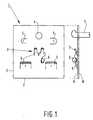
- Figure 1shows a prior art presentation element.
- presentation elementsare frequently used in boutiques, jeweller's shops, department stores and the like for displaying and presenting articles intended for sale, such as ornaments, pieces of jewellery and the like.
- presentation element 1is a rectangular element which is made of a plastic material or of cardboard, and which is provided with holes and cutouts 5.
- Presentation element 1comprises edges 2 and a central portion 3, which is capable of accommodating a random article 6, in this case a piece of jewellery (an earring).
- To that end presentation element 1is provided with means, in this case consisting of holes and/or cutouts 5, for receiving article 6.
- a suspension opening 4In addition to that presentation element 1 is provided with a suspension opening 4.
- one drawback of the presentation elementis the fact that it no longer has a function once the article has been purchased by the consumer.
- the consumerconsiders the presentation element a useless residual throw-away product, which does not have any function.
- the purchased articlemust be packed by the shop staff as yet, which additional operations to be performed in the shop take up time and cost money, whilst furthermore additional waste material is created.
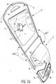
- FIG. 2ashows an embodiment of a presentation element according to the present invention.
- the presentation elementcomprises two element parts 11 and 12, which are connected by means of a hinge 17.
- Plasticis a strong and inexpensive material, which is simple to process, so that the presentation element can be produced in large numbers by using simple techniques, such as injection moulding techniques. Other materials are also suitable, however.
- the presentation elementmay also consist of two separate element parts, whereby element parts 11 and 13 are connected without using a hinged joint.
- First element part 11comprises edges 13 and a central portion 14, whilst second element part 12 comprises edges 15 and a central portion 16.
- means 20 for accommodating an article intended for saleare provided in central portion 14 of first element part 11. Such an article can be clamped down or attached in central portion 14 with the aid of central portion 20.
- central portions 14 and 16 of first and second element parts 11 and 12respectively are recessed.
- Central portion 14 of first element part 11may also be a flat central portion, however, that is, coincide with or extend parallel to the plane of edges 13.
- Recessed central portion 16 of second element partis formed in such a manner that the central portion can be deformed from the plane of edges 15.
- Deformable central portion 16is provided with a number of bending and/or folding lines 19 to this end. The thickness of the material at bending and/or folding lines 19 is smaller than that of the rest of second element part 12.
- central portion 16By exerting an external pressure force on the convex part of central portion 16, for example with one or more fingers, the material of central portion 16 can be deformed, as a result of which the material will buckle along thinner bending and/or lines 19, and the elevated central portion 16 is converted into a recessed central portion 16 on side C of the second element part.
- This deformation of central portion 16 along bending and/or folding lines 19is reversible, so that second element part 12 can be formed with a recessed or with an elevated central portion 16, seen from side C, by exerting a pressure force on the convex part of central portion 16.
- Double film hinge 17enables second element part 12 to pivot through angles -180° and +180°.
- second element part 12comes to butt with edges 15 against edges 13 of first element part 11, on the second side thereof, when being pivoted through -180°. Since the dimensions of recessed central portion 16 are slightly larger than those of central portion 14, central portion 16 will cover central portion 14 of first element part 11 upon being pivoted through -180°. Central portion 16 of second element part 12 and central portion 14 of first element part 11 nest one into the other thereby.
- First side A of first element part 11is turned toward the consumer thereby, so that an article present in central portion 14 can be displayed or presented in such a manner that it is exposed to the consumer's view. See also Figure 2b in connection with this.
- the deformable central portion 16When pivoting takes place through +180°, the deformable central portion 16 must first be deformed by exerting an external pressure force on the convex part of central portion 16, in such a manner that, seen from side C of second element part 12, the elevated central portion 16 will deform along bending and/or folding lines 19 into a recessed central portion 16.
- First and second element parts 11 and 12are joined into a compact structure upon being pivoted through a further +180°, whereby the edges 15 of second element part 12 butt against the edges 13 of first element part 11, on first side A thereof, and central portion 16 envelops central portion 14 and the article accommodated therein. See also Figure 2c in connection with this.
- Figure 2bshows the presentation element according to the present invention in the so-called presentation position.
- Second element part 12thereby butts with edges 15 against edges 13 of first element part 11, on second side B thereof, as a result of being pivoted through -180°, whereby deformable central portion 16 covers central portion 14 on side B of element part 11.
- the two suspension openings 18coincide, so that the presentation element, together with a large number of identical presentation elements, can be suspended in side-by-side relationship or in a row in a known display or presentation device (not shown) in a shop.
- First side Awhich accommodates an article intended for sale in central portion 14 thereof, is thereby turned towards the consumer, so that a customer-friendly presentation is obtained with such a structure, which structure takes up little space as a result of central portions 14 and 16 nesting one into the other.
- Figure 2cshows the presentation element according to the present invention in the so-called packaging position.
- the presentation element as shown in Figure 2bis adjusted by the shop staff to the packaging position as shown in Figure 2c when the customer pays for the article.
- central portion 16is deformed along bending and/or folding lines 19 by exerting an external pressure force with one or more fingers on the convex part of deformable central portion 16 when pivoting through +180° takes place, in such a manner that central portion 16 buckles along bending and/or folding lines 19 to a recessed central portion 16, seen from side C of second element part 12.
- First and second element parts 11 and 12are then joined upon being pivoted through a further +180°, in such a manner that edges 15 butt against the edges 13 of first element part 11, on first side A thereof, and central portion 16 envelops the purchased article.
- These operationscan be quickly carried out in a simple manner by the shop staff. All this leads to a reduction and simplification of the operations to be performed in the shop, which take up time and cost money. Since the structure also provides a functional, strong and reusable packaging of the article for the consumer, the amount of residual and waste material is accordingly reduced.
- the use of a specific colour combination and print and/or an engraving formed during the injection moulding processfurthermore makes it possible to produce a reusable package which is attractive to the consumer, which will retain its function also after the purchase of the article, and which is not considered as a useless, residual throw-away product.
- the two element parts 11 and 12are transparent, at least partially so, which makes the presentation and packaging of the article more attractive.
- the presentation elementis also suitable for articles having larger dimensions and a larger volume.
- the edges 13 and 15 of the two element parts 11 and 12respectively may be provided with snap connection means, so that the abutting edges clampingly engage each other both in the presentation position (Figure 2b) and in the packaging position ( Figure 2c).
- the two element partsmay be attached together in different manners, both in the presentation position and in the packaging position.
- the central portions of the two element partsmay also be made up of the entire element part, with the bending and/or folding lines coinciding with the edges of the element parts.
Landscapes
- Chemical & Material Sciences (AREA)
- Composite Materials (AREA)
- Engineering & Computer Science (AREA)
- Mechanical Engineering (AREA)
- Packaging Of Annular Or Rod-Shaped Articles, Wearing Apparel, Cassettes, Or The Like (AREA)
- Packages (AREA)
Abstract
Description
Claims (11)
- A presentation element suitable for displaying orpresenting articles intended for sale, for exampleornaments, pieces of jewellery and the like, whichpresentation element comprises a first element partcomprising edges and a central portion for accommodating anarticle on a first side of said first element part,characterized in that the presentation element comprises asecond element part connected to said first element part,which comprises edges and a deformable central portion, whichsecond element part can be adjusted into a first position,wherein the edges of said second element part butt againstthe edges of said first element part, on the first sidethereof, and wherein said deformable central portion envelopsthe article.
- A presentation element according to claim 1,characterized in that said second element part can beadjusted into a second position, wherein the edges of saidsecond element part butt against the edges of the firstelement part, on a second side thereof, and wherein saiddeformable central portion covers the central portion of saidfirst element part on the second side thereof.
- A presentation element according to claim 1 or 2,characterized in that the deformable central portion of thesecond element part is deformable from the plane of theedges.
- A presentation element according to any one of thepreceding claims,characterized in that the deformablecentral portion of said second element part is provided withbending and/or folding lines.
- A presentation element according to any one of thepreceding claims,characterized in that said first and saidsecond element part are pivotally connected, in particular bymeans of a single or a double film hinge.
- A presentation element according to any one of thepreceding claims,characterized in that the edges of thefirst and the second element are provided with snap connection means.
- A presentation element according to any one of thepreceding claims,characterized in that said first elementpart is provided with means for accommodating an article.
- A presentation element according to any one of thepreceding claims,characterized in that the central portionof said first element part is a recessed central portion.
- A presentation element according to any one of thepreceding claims,characterized in that said first and/orsaid second element part are provided with suspension means.
- A presentation element according to any one of thepreceding claims,characterized in that the presentationelement is made of plastic material, in particular ofpolypropylene or polyethylene.
- A presentation element according to any one of thepreceding claims,characterized in that said first and/orsaid second element part are at least partially transparent.
Applications Claiming Priority (2)
| Application Number | Priority Date | Filing Date | Title |
|---|---|---|---|
| NL1005295 | 1997-02-17 | ||
| NL1005295ANL1005295C2 (en) | 1997-02-17 | 1997-02-17 | Presentation element. |
Publications (2)
| Publication Number | Publication Date |
|---|---|
| EP0862879A1true EP0862879A1 (en) | 1998-09-09 |
| EP0862879B1 EP0862879B1 (en) | 2002-10-09 |
Family
ID=19764435
Family Applications (1)
| Application Number | Title | Priority Date | Filing Date |
|---|---|---|---|
| EP98200326AExpired - LifetimeEP0862879B1 (en) | 1997-02-17 | 1998-02-04 | Presentation element |
Country Status (4)
| Country | Link |
|---|---|
| US (1) | US6065589A (en) |
| EP (1) | EP0862879B1 (en) |
| DE (1) | DE69808531T2 (en) |
| NL (1) | NL1005295C2 (en) |
Families Citing this family (29)
| Publication number | Priority date | Publication date | Assignee | Title |
|---|---|---|---|---|
| US6244431B1 (en)* | 1999-03-03 | 2001-06-12 | Vanfleet Dorothy | Jewelry hanger and organizer |
| US6227369B1 (en) | 1999-10-29 | 2001-05-08 | Sony Corporation | Clamshell package including both permanent and resealable fastening structure |
| US6330945B1 (en)* | 2000-06-30 | 2001-12-18 | Placon Corporation | Clamshell package with curved card |
| USD472071S1 (en) | 2001-08-09 | 2003-03-25 | Target Brands, Inc. | Merchandise display holder |
| USD471442S1 (en) | 2001-12-12 | 2003-03-11 | Monster Cable Products, Inc. | Display package |
| USD466405S1 (en) | 2001-12-12 | 2002-12-03 | Monster Cable Products, Inc. | Display package |
| US20030159963A1 (en)* | 2002-01-18 | 2003-08-28 | Thoughtworks, Ltd. | Rocking package |
| US6968951B2 (en)* | 2002-03-01 | 2005-11-29 | Nokia Corporation | Packaging |
| USD467493S1 (en) | 2002-03-05 | 2002-12-24 | Intec, Inc. | Packaging for an electronic game accessory |
| DE10210825A1 (en)* | 2002-03-12 | 2003-10-02 | Abb Patent Gmbh | Packaging system for at least one electrical installation device |
| US6920980B2 (en)* | 2002-06-24 | 2005-07-26 | Hewlett-Packard Development Company, L.P. | Container |
| USD479461S1 (en) | 2002-09-09 | 2003-09-09 | Thermal Dynamics Corporation | Packaging for cutting or welding equipment |
| USD493981S1 (en) | 2002-10-08 | 2004-08-10 | Silhouette International Schmied Ag | Optical display case |
| USD509730S1 (en)* | 2002-10-17 | 2005-09-20 | Techpak International | Container |
| USD502869S1 (en)* | 2003-04-24 | 2005-03-15 | Kevin Clarke & Co. Ltd. | Box |
| US6942098B1 (en) | 2003-07-01 | 2005-09-13 | Charles Dodge | Storage device for face protection gear |
| US20050269232A1 (en)* | 2004-06-03 | 2005-12-08 | Eisenbraun Kenneth D | Transparent packaging with imprint applied after closing |
| USD535836S1 (en) | 2004-09-28 | 2007-01-30 | Silhouette International Schmied Ag | Display case for eyewear |
| US7338396B2 (en)* | 2005-09-08 | 2008-03-04 | Rawlings Sporting Goods Company, Inc. | Preformed lacrosse pocket and packaging for same |
| US7537109B1 (en)* | 2007-03-22 | 2009-05-26 | Glamour Rings Of Hawaii, Inc. | Ring packaging |
| USD593854S1 (en)* | 2008-06-25 | 2009-06-09 | Eveready Battery Company, Inc. | Battery package |
| USD598742S1 (en) | 2008-08-21 | 2009-08-25 | S.C. Johnson & Son, Inc. | Package for a cleaning article |
| US20100059401A1 (en)* | 2008-09-10 | 2010-03-11 | All About Packaging Inc | Blister package having a securement mechanism and a method of forming and filing said blister package |
| US7926658B2 (en)* | 2008-09-10 | 2011-04-19 | All About Packaging Inc. | Blister package having securement mechanism and method of forming and filling the blister package |
| USD615395S1 (en)* | 2009-06-19 | 2010-05-11 | Mga Entertainment | Product package |
| US8800768B2 (en)* | 2012-05-31 | 2014-08-12 | Milwaukee Electric Tool Corporation | Clamshell packaging |
| USD910433S1 (en)* | 2017-04-28 | 2021-02-16 | The Procter & Gamble Company | Air freshener package |
| US11008145B2 (en) | 2017-04-28 | 2021-05-18 | The Procter & Gamble Company | Packing system and method of packing |
| USD903483S1 (en)* | 2018-11-16 | 2020-12-01 | Stasher, Inc. | Sealable container |
Citations (3)
| Publication number | Priority date | Publication date | Assignee | Title |
|---|---|---|---|---|
| FR2302936A1 (en)* | 1975-03-03 | 1976-10-01 | Landstingens Inkopscentral | CONTAINER SUITABLE FOR SMALL QUANTITIES OF FLUID OR SEMI-FLUID SUBSTANCES |
| EP0115990A1 (en)* | 1983-01-28 | 1984-08-15 | Michel Guiffray | Flexible material container for liquids |
| US5293993A (en)* | 1991-06-14 | 1994-03-15 | Dynamic Bio-Apparatuses, Inc. | Syringe sealing container |
Family Cites Families (6)
| Publication number | Priority date | Publication date | Assignee | Title |
|---|---|---|---|---|
| US4158411A (en)* | 1976-05-10 | 1979-06-19 | Hall Douglas C | Dispensing package |
| US4574954A (en)* | 1984-12-07 | 1986-03-11 | Medication Services Inc. | Pill dispenser |
| US4676446A (en)* | 1986-01-28 | 1987-06-30 | W. H. Brady Co. | Adhesive tape dispenser package with interlocking cover members |
| US5029705A (en)* | 1989-09-08 | 1991-07-09 | Schmidt-Conner Joint Venture Group | Selectively configurable package for retaining separated items |
| US5143215A (en)* | 1990-06-27 | 1992-09-01 | P.T.P. Industries | Battery display package |
| US5188222A (en)* | 1991-10-11 | 1993-02-23 | Sounds Fun, Inc. | Anti-theft display package for animated talking time pieces |
- 1997
- 1997-02-17NLNL1005295Apatent/NL1005295C2/ennot_activeIP Right Cessation
- 1998
- 1998-02-04EPEP98200326Apatent/EP0862879B1/ennot_activeExpired - Lifetime
- 1998-02-04DEDE69808531Tpatent/DE69808531T2/ennot_activeExpired - Fee Related
- 1998-02-12USUS09/022,388patent/US6065589A/ennot_activeExpired - Fee Related
Patent Citations (3)
| Publication number | Priority date | Publication date | Assignee | Title |
|---|---|---|---|---|
| FR2302936A1 (en)* | 1975-03-03 | 1976-10-01 | Landstingens Inkopscentral | CONTAINER SUITABLE FOR SMALL QUANTITIES OF FLUID OR SEMI-FLUID SUBSTANCES |
| EP0115990A1 (en)* | 1983-01-28 | 1984-08-15 | Michel Guiffray | Flexible material container for liquids |
| US5293993A (en)* | 1991-06-14 | 1994-03-15 | Dynamic Bio-Apparatuses, Inc. | Syringe sealing container |
Also Published As
| Publication number | Publication date |
|---|---|
| DE69808531D1 (en) | 2002-11-14 |
| DE69808531T2 (en) | 2003-06-26 |
| US6065589A (en) | 2000-05-23 |
| NL1005295C2 (en) | 1998-08-18 |
| EP0862879B1 (en) | 2002-10-09 |
Similar Documents
| Publication | Publication Date | Title |
|---|---|---|
| EP0862879B1 (en) | Presentation element | |
| US4420084A (en) | Jewelry holding device | |
| US4899971A (en) | Display assembly | |
| JPH0352459Y2 (en) | ||
| US5933994A (en) | Retail checkout divider adapted to receive strips with indicia displayed thereon | |
| US5340074A (en) | Eyeglass display hanger | |
| HUP9902280A2 (en) | Display box for holding individual articles | |
| US5078264A (en) | Jewelry display card | |
| US7938535B2 (en) | Eyewear and case display apparatus | |
| US4043449A (en) | Gift package containing message bearing unit and useful article in association therewith | |
| US5312001A (en) | Paint chip display assembly | |
| US5197596A (en) | Display card | |
| US5260726A (en) | Hanger for displaying eyeglasses | |
| US6684546B1 (en) | Printed decorating painting | |
| US6352151B1 (en) | Jewelry box having attached segmented lid member | |
| US6968951B2 (en) | Packaging | |
| US20050035013A1 (en) | Packaging for hanging tool display | |
| US6772880B2 (en) | Clothes hanger package | |
| US5322159A (en) | Hanging display improvement for nesting containers | |
| KR200429695Y1 (en) | Packing case for piece cake | |
| US5215700A (en) | Method of molding a display card | |
| EP0800156A1 (en) | Labelholder for the presentation of informations relating to objects stocked in the shelves of a warehouse | |
| US7111726B1 (en) | Protective display and gift package | |
| KR101991501B1 (en) | An packing case for display | |
| JPWO2019021967A1 (en) | Product package |
Legal Events
| Date | Code | Title | Description |
|---|---|---|---|
| PUAI | Public reference made under article 153(3) epc to a published international application that has entered the european phase | Free format text:ORIGINAL CODE: 0009012 | |
| AK | Designated contracting states | Kind code of ref document:A1 Designated state(s):DE ES FR GB IT | |
| AX | Request for extension of the european patent | Free format text:AL;LT;LV;MK;RO;SI | |
| 17P | Request for examination filed | Effective date:19990128 | |
| AKX | Designation fees paid | Free format text:DE ES FR GB IT | |
| RBV | Designated contracting states (corrected) | Designated state(s):DE ES FR GB IT | |
| GRAG | Despatch of communication of intention to grant | Free format text:ORIGINAL CODE: EPIDOS AGRA | |
| 17Q | First examination report despatched | Effective date:20020122 | |
| GRAG | Despatch of communication of intention to grant | Free format text:ORIGINAL CODE: EPIDOS AGRA | |
| GRAH | Despatch of communication of intention to grant a patent | Free format text:ORIGINAL CODE: EPIDOS IGRA | |
| GRAH | Despatch of communication of intention to grant a patent | Free format text:ORIGINAL CODE: EPIDOS IGRA | |
| GRAA | (expected) grant | Free format text:ORIGINAL CODE: 0009210 | |
| AK | Designated contracting states | Kind code of ref document:B1 Designated state(s):DE ES FR GB IT | |
| PG25 | Lapsed in a contracting state [announced via postgrant information from national office to epo] | Ref country code:IT Free format text:LAPSE BECAUSE OF FAILURE TO SUBMIT A TRANSLATION OF THE DESCRIPTION OR TO PAY THE FEE WITHIN THE PRESCRIBED TIME-LIMIT;WARNING: LAPSES OF ITALIAN PATENTS WITH EFFECTIVE DATE BEFORE 2007 MAY HAVE OCCURRED AT ANY TIME BEFORE 2007. THE CORRECT EFFECTIVE DATE MAY BE DIFFERENT FROM THE ONE RECORDED. Effective date:20021009 Ref country code:FR Free format text:LAPSE BECAUSE OF FAILURE TO SUBMIT A TRANSLATION OF THE DESCRIPTION OR TO PAY THE FEE WITHIN THE PRESCRIBED TIME-LIMIT Effective date:20021009 | |
| REG | Reference to a national code | Ref country code:GB Ref legal event code:FG4D | |
| REF | Corresponds to: | Ref document number:69808531 Country of ref document:DE Date of ref document:20021114 | |
| PG25 | Lapsed in a contracting state [announced via postgrant information from national office to epo] | Ref country code:ES Free format text:LAPSE BECAUSE OF FAILURE TO SUBMIT A TRANSLATION OF THE DESCRIPTION OR TO PAY THE FEE WITHIN THE PRESCRIBED TIME-LIMIT Effective date:20030429 | |
| PGFP | Annual fee paid to national office [announced via postgrant information from national office to epo] | Ref country code:GB Payment date:20030728 Year of fee payment:6 | |
| PGFP | Annual fee paid to national office [announced via postgrant information from national office to epo] | Ref country code:DE Payment date:20030731 Year of fee payment:6 | |
| EN | Fr: translation not filed | ||
| PLBE | No opposition filed within time limit | Free format text:ORIGINAL CODE: 0009261 | |
| STAA | Information on the status of an ep patent application or granted ep patent | Free format text:STATUS: NO OPPOSITION FILED WITHIN TIME LIMIT | |
| 26N | No opposition filed | Effective date:20030710 | |
| PG25 | Lapsed in a contracting state [announced via postgrant information from national office to epo] | Ref country code:GB Free format text:LAPSE BECAUSE OF NON-PAYMENT OF DUE FEES Effective date:20040204 | |
| PG25 | Lapsed in a contracting state [announced via postgrant information from national office to epo] | Ref country code:DE Free format text:LAPSE BECAUSE OF NON-PAYMENT OF DUE FEES Effective date:20040901 | |
| GBPC | Gb: european patent ceased through non-payment of renewal fee | Effective date:20040204 |