EP0862677B1 - Universal wrap security device - Google Patents
Universal wrap security deviceDownload PDFInfo
- Publication number
- EP0862677B1 EP0862677B1EP96913302AEP96913302AEP0862677B1EP 0862677 B1EP0862677 B1EP 0862677B1EP 96913302 AEP96913302 AEP 96913302AEP 96913302 AEP96913302 AEP 96913302AEP 0862677 B1EP0862677 B1EP 0862677B1
- Authority
- EP
- European Patent Office
- Prior art keywords
- security device
- base
- reel
- pawl
- cable
- Prior art date
- Legal status (The legal status is an assumption and is not a legal conclusion. Google has not performed a legal analysis and makes no representation as to the accuracy of the status listed.)
- Expired - Lifetime
Links
- 239000002184metalSubstances0.000claimsdescription13
- 230000007246mechanismEffects0.000claimsdescription8
- 239000000463materialSubstances0.000description5
- 238000000034methodMethods0.000description3
- 239000000126substanceSubstances0.000description3
- 239000011521glassSubstances0.000description2
- 238000005192partitionMethods0.000description2
- 239000000853adhesiveSubstances0.000description1
- 230000001070adhesive effectEffects0.000description1
- 238000013475authorizationMethods0.000description1
- 239000000835fiberSubstances0.000description1
- JEIPFZHSYJVQDO-UHFFFAOYSA-Niron(III) oxideInorganic materialsO=[Fe]O[Fe]=OJEIPFZHSYJVQDO-UHFFFAOYSA-N0.000description1
- 230000002093peripheral effectEffects0.000description1
- 238000009877renderingMethods0.000description1
- 238000003466weldingMethods0.000description1
Images


Classifications
- A—HUMAN NECESSITIES
- A45—HAND OR TRAVELLING ARTICLES
- A45C—PURSES; LUGGAGE; HAND CARRIED BAGS
- A45C13/00—Details; Accessories
- A45C13/18—Devices to prevent theft or loss of purses, luggage or hand carried bags
- A45C13/20—Chains or bands
- A—HUMAN NECESSITIES
- A47—FURNITURE; DOMESTIC ARTICLES OR APPLIANCES; COFFEE MILLS; SPICE MILLS; SUCTION CLEANERS IN GENERAL
- A47F—SPECIAL FURNITURE, FITTINGS, OR ACCESSORIES FOR SHOPS, STOREHOUSES, BARS, RESTAURANTS OR THE LIKE; PAYING COUNTERS
- A47F3/00—Show cases or show cabinets
- A47F3/002—Devices for protection against sunlight or theft
- E—FIXED CONSTRUCTIONS
- E05—LOCKS; KEYS; WINDOW OR DOOR FITTINGS; SAFES
- E05B—LOCKS; ACCESSORIES THEREFOR; HANDCUFFS
- E05B35/00—Locks for use with special keys or a plurality of keys ; keys therefor
- E05B35/008—Locks for use with special keys or a plurality of keys ; keys therefor for simple tool-like keys
- E—FIXED CONSTRUCTIONS
- E05—LOCKS; KEYS; WINDOW OR DOOR FITTINGS; SAFES
- E05B—LOCKS; ACCESSORIES THEREFOR; HANDCUFFS
- E05B73/00—Devices for locking portable objects against unauthorised removal; Miscellaneous locking devices
- E05B73/0017—Anti-theft devices, e.g. tags or monitors, fixed to articles, e.g. clothes, and to be removed at the check-out of shops
- E05B73/0029—Tags wrapped around the protected product using cables, wires or the like, e.g. with cable retraction for tensioning
- Y—GENERAL TAGGING OF NEW TECHNOLOGICAL DEVELOPMENTS; GENERAL TAGGING OF CROSS-SECTIONAL TECHNOLOGIES SPANNING OVER SEVERAL SECTIONS OF THE IPC; TECHNICAL SUBJECTS COVERED BY FORMER USPC CROSS-REFERENCE ART COLLECTIONS [XRACs] AND DIGESTS
- Y10—TECHNICAL SUBJECTS COVERED BY FORMER USPC
- Y10T—TECHNICAL SUBJECTS COVERED BY FORMER US CLASSIFICATION
- Y10T24/00—Buckles, buttons, clasps, etc.
- Y10T24/14—Bale and package ties, hose clamps
- Y10T24/1402—Packet holders
- Y10T24/1404—Cord
- Y—GENERAL TAGGING OF NEW TECHNOLOGICAL DEVELOPMENTS; GENERAL TAGGING OF CROSS-SECTIONAL TECHNOLOGIES SPANNING OVER SEVERAL SECTIONS OF THE IPC; TECHNICAL SUBJECTS COVERED BY FORMER USPC CROSS-REFERENCE ART COLLECTIONS [XRACs] AND DIGESTS
- Y10—TECHNICAL SUBJECTS COVERED BY FORMER USPC
- Y10T—TECHNICAL SUBJECTS COVERED BY FORMER US CLASSIFICATION
- Y10T70/00—Locks
- Y10T70/40—Portable
- Y10T70/413—Padlocks
- Y10T70/437—Key-controlled
- Y10T70/483—Flexible shackle
- Y—GENERAL TAGGING OF NEW TECHNOLOGICAL DEVELOPMENTS; GENERAL TAGGING OF CROSS-SECTIONAL TECHNOLOGIES SPANNING OVER SEVERAL SECTIONS OF THE IPC; TECHNICAL SUBJECTS COVERED BY FORMER USPC CROSS-REFERENCE ART COLLECTIONS [XRACs] AND DIGESTS
- Y10—TECHNICAL SUBJECTS COVERED BY FORMER USPC
- Y10T—TECHNICAL SUBJECTS COVERED BY FORMER US CLASSIFICATION
- Y10T70/00—Locks
- Y10T70/50—Special application
Definitions
- the inventionrelates to a security device. More particularly the invention relates to an adjustable security device which wraps around and secures a box, book, or other similarly structured articles of various sizes in a closed position. Even more particularly the invention relates to a universal wrap security device which includes a plurality of wires or cables that wrap around the article and extend between a ratchet member and a locking member, both of which require a special tool to operate.
- Retail storeshave a difficult time protecting boxes containing various expensive merchandise, books and other similarly structured packages or objects from being opened and the contents thereof being removed without authorization from store personnel or damaged while on display. Consumers often want to visually inspect the packaged expensive articles before deciding to purchase them. The store is faced with the problem of how to protect these expensive articles from theft while displaying them for sale.
- One method used to protect these packages and the articles contained thereinis to enclose the article within a transparent glass display case which can only be accessed from behind a counter of the retail store. The consumer can view the article through the glass but is not able to handle the article or read any of the information about the article that may be printed on the box unless a store clerk removes the article from the case.
- a store clerkremoves the article from the case.
- the problemthen arises of getting the selected merchandise to the customer after the customer wishes to purchase the same without subjecting the merchandise to theft.
- One manneris to maintain a supply of the boxes containing the expensive articles or merchandise close at hand for delivery to or pick-up by the customer for subsequent taking to a check-out. clerk. However this makes the boxes susceptible to theft.
- Another method used by retail storesis to list the article in a catalog and require consumers to place an order from the catalog.
- the articleis delivered from a back storage area and the consumer must simultaneously pick up and pay for the merchandise at the same location to prevent unauthorized removal from the store.
- the consumerdoes not get to inspect the article before purchasing and if they are not satisfied they must undergo the hassle of returning the article for a refund.
- Boxes and box-like structuresare also subjected to unauthorized openings while being shipped via a courier. These articles can be easily opened and resealed when packaged and taped-shut in the conventional manner without the recipient or the sender knowing of such actions. Shipped packages can be secured within a security container with a locking mechanism but these containers are expensive to purchase and add size and weight to the package making it more expensive to ship. Also, would-be thieves can gain unauthorized access to the contents of these containers by "picking" the locking mechanisms or possibly guessing the combination to a combination lock.
- US-A-3,611,760discloses a locking device which utilizes a retractable cable mounted in a housing, wherein the cable loops around an object to be secured, and is then locked in the housing by a combination lock.
- US-A-4,756,171discloses a locking device having a cable which extends about the object to be secured, together with a take-up reel mounted in the lock member for tightening the cable by a crank handle in the lock member.
- US-A-4,896,517discloses a locking device which has a cable with a locking head wound about a reel having a ratchet and pawl locking mechanism. The locking head engages the locking mechanism to secure the cable in a locked position.
- US-A-5,156,028discloses a portable locking device using a ratchet-like retrieving reel, to which is connected a locking cable.
- US-A-3,831,407discloses a locking device consisting of a plurality of flexible wire-like members which extend about an object to be secured, with open ends of the chains being secured by a lock.
- US-A-4,418,551discloses a security device which is mounted about a rectangular object, such as a vending machine.
- the deviceincludes a strap structure extending around portions of the rectangular object, a door moveable between open and closed positions, and a locking mechanism to lock the door in the closed position.
- US-A-4,930,324discloses a lockable buckle which has a rotatably mounted tumbler in a lock housing which locks a clasp member to the housing.
- none of these prior art devicesinclude a portable lightweight device which has a ratchet member which uses a tool to tighten a plurality of cable or cable sections around box-like structures of various sizes, and which has a two-piece locking member which snap-fits together and uses an unlocking tool or key with magnetic arms to dismantle the two-piece locking member before the article contained within the box can be removed therefrom.
- a universal security devicewhich includes a ratchet member and a locking member, which uses two separate tools to operate the device, which encloses the package on all six sides, which includes a one-way ratchet which can be released only after the device is removed from the package, which can be reused indefinitely, which does not add significant size or weight to the package, and which is readily adjustable for a variety of sized boxes.
- a universal security devicewhich includes a ratchet member and a locking member, which uses two separate tools to operate the device, which encloses the package on all six sides, which includes a one-way ratchet which can be released only after the device is removed from the package, which can be reused indefinitely, which does not add significant size or weight to the package, and which is readily adjustable for a variety of sized boxes.
- the security device of the present inventionincludes a plurality of wires or cables which encircle and lock all six sides of a box, package, book or other similar structure.
- the cableextends between a ratchet member which includes a gear with a plurality of teeth, a one-way pawl which engages the teeth, and a locking member which includes a fastener which snap-fits to a base and requires an unlocking tool to unlock.
- the one-way ratchetalso requires a tool to tighten the cables around the package being protected, and the pawl which can be disengaged from the ratchet teeth only from a rear side of the ratchet member after the device has been removed from the package.
- objectives of the present inventioninclude providing a security device which includes a ratchet member and a locking member and a plurality of cables extending between said members and around an object to be secured in a closed position.
- Another objective of the present inventionis to provide such a security device which requires two separate tools to lock and unlock the device and tighten the cables around the article being protected by the device.
- a further objective of the present inventionis to provide such a security device which encloses the object or package on all six sides.
- a still further objective of the present inventionis to provide such a security device which includes a one-way ratchet which can be released only after the device has been removed from the package.
- Another objective of the present inventionis to provide such a security device which can be reused indefinitely, and which does not add significant size or weight to the package, and which can be formed of a high-strength plastic material not readily affected by chemicals and moisture.
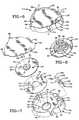
- Security device 1includes a locking member 3, a ratchet member 4 and a plurality of connecting cables 5.
- Locking member 3includes two main components, a fastener 7 (FIGS. 2-5) which is inserted and locks into an oval-shaped base 8.
- Fastener 7has a leg 10 (FIGS. 2 and 3) integrally formed with and extending from an ear shaped lug 11.
- Leg 10includes a rectangular-shaped center post 13 intermediate two spaced generally parallel tangs 15 and 16.
- a U-shaped groove 14is formed in a back side of post 13.
- each tang 15 and 16is angled inwardly toward post 13, and post 13 and tangs 15 and 16 are connected integrally at a free end 17.
- End 17has rounded edges 18 which extend beyond the inwardly angled portions of tangs 15 and 16 and form flat locking tabs 19.
- a circular opening 22is formed in lug 11 and allows cable 5 to extend therethrough.
- a pair of notches 23are formed in each side of lug 11 on a flat side thereof, and assist in guiding fastener 7 into base 8 and centrally stabilizes fastener 7 therein, as described below in further detail.
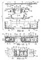
- Base 8includes an oval-shaped bottom member 26 which has an upstanding curved side wall 27 extending partially around the perimeter of bottom member 26, and a pair of end walls 28 extending inwardly from opposite ends of wall 27.
- a pair of tapered prongs 29extend inwardly perpendicularly from an end of each end wall 28.
- a pair of tabs 30extend inwardly parallel to a tapered edge of prongs 29 and further extend from end walls 28 between outer wall 27 and prongs 29.
- a pair of substantially L-shaped metal tines 35are inserted and secured between prongs 29 and tabs 30, and extend angularly inwardly and terminate adjacent a second end wall 39 (FIGS. 3 and 4).
- Wall 39is spaced from and parallel to end walls 28 and a third end wall 40 is spaced outwardly from and parallel to second end wall 39 forming a channel 42 therebetween through which another portion of cable 5 extends.
- An elongated rib 34is perpendicular to wall 39 and extends inwardly partially across the longitudinal length of bottom member 26 of base 8 and is received in groove 14 of fastener 7 when locking member 3 is in a locked position as shown in FIGS. 4 and 5.
- An oval shaped cover 44(FIGS. 2-5) generally similar in size to bottom member 26 encloses base 8 and is seated upon a generally oval-shaped shoulder 45 formed inside of and extending along side wall 26.
- leg 10 of fastener 7slides between prongs 29 when pressure is applied to fastener 7 in the direction of arrow A (FIG. 4), and groove 14 of leg 10 receives and is guided by rib 34.
- Rounded edges 18 of end 17deflect tines 35 outwardly as fastener 7 is inserted into base 8.
- lug 11fills an open area 36 (FIGS. 2 and 3) of bottom member 26 and abuts end walls 28.
- Notches 23receive a pair of shoulders 37 which are formed on each end of wall 27, and the resiliency of metal tines 35 causes them to snap into a locked position adjacent to the angular outer portions of tangs 15 and 16.
- Tines 35cooperate with tabs 19 of leg 10 and prevent fastener 7 from being removed from base 8.
- Locking member 3except for metal tines 35, preferably is formed of a lightweight, high-strength plastic material which is relatively rust free and unaffected by chemicals and harsh environments to which it may be exposed, with base 8 and cover plate 44 being molded as one-piece members and subsequently secured together by an adhesive, ultrasonic welding, or other type of securement means.
- Ratchet member 4is shown assembled in FIG. 6 and unassembled in FIG. 7.
- Ratchet member 4includes a housing 50 which is separated into a generally circular compartment 51 and a smaller adjacent compartment 53 by a partition wall 55.
- a circular-shaped bearing member 54 and a circular-shaped gear 56are housed within compartment 51 and a pawl 52 is housed within compartment 53. Both compartments 51 and 53 and the contents therein are enclosed by a bottom plate 58.
- a circular opening 60is formed in a front wall 62 of housing 50 and an annular groove or bearing surface 64 is formed around circular opening 60.
- Side wall 65 of housing 50extends vertically upwardly from front wall 62 and includes an outwardly extending lip or shoulder 66 upon which bottom plate 58 sits when secured to housing 50.
- U-shaped openings 68are formed in side wall 65 in a square-shaped configuration and allow four cable sections to pass therethrough, with each cable section being generally perpendicular to the adjacent two cable sections.
- Bottom plate 58includes four flanges 69 with an arcuate shaped bottom, which align and cooperate with U-shaped openings 68 to form circular shaped openings 70 therebetween (FIG. 6).
- FIG. 7Another circular opening 73 is formed in the center of bearing member 54 (FIG. 7) and an annular nub 75 (FIG. 9) which corresponds to and is received by bearing surface 64, is formed on a bottom surface of bearing member 54.
- Four flexible projections 76(FIGS. 7 and 9), which include outward extending latching tabs 77, extend orthogonally from bearing member 54 and are arranged in a square-shaped configuration.
- Gear 56is shown particularly in FIGS. 7 and 8 and releasably latches to bearing member 54 when ratchet member 4 is assembled as shown in FIGS. 10 and 11.
- a plurality of teeth 80extend around an outside edge of gear 56.
- Gear 56further includes a disc-shaped plate 82 and a center hub 84 which extends vertically from plate 82.
- Four openings 85are formed in hub 84 for receiving and retaining an enlarged end 88 of each section of cable 5 as shown in FIG. 12.
- Four irregular-shaped holes 90are formed in hub 84 partially therethrough and four rectangular-shaped holes 91 which communicate with holes 90 are formed completely through gear 56 (FIG. 12).
- Holes 91receive projections 76 of bearing member 54 and allow latching tabs 77 to secure bearing member 54 to gear 56 to form a cable-receiving reel 100.
- a bore 94is formed through the center of gear 56 and includes a seven sided surface 95 formed in hub 84, a smaller circular opening 96 formed in an annular plate 99 concentrically with and adjacent to seven sided surface 95 (FIGS. 7, 8, 9 and 12) and a larger circular section 97 formed in plate 82 concentrically with and adjacent to circular opening 96 and annular plate 99.
- An annular nub 101is formed on a top surface of plate 82 of gear 56 concentrically with bore 94 and is received by a bearing surface 71 formed in bottom plate 58 when ratchet member 4 is assembled as shown in FIGS. 9 and 10.
- Pawl 52has a cylindrical base 105 (FIG. 7), a smaller cylindrical section 106 which has a five-sided central opening 107 formed therein, a resilient spring 108 and a pawl catch 110, both of which extend from a side wall of cylindrical section 105.
- Pawl 52is mounted in compartment 53 and is seated upon a circular boss 103 formed on wall 62 (FIG. 11).
- Cylindrical section 106extends through a complementary-shaped hole 59 formed in bottom plate 58 (FIGS. 6 and 7) which clamps pawl 52 within housing 50.
- Resilient spring 108applies pressure on the inside of side wall 65 forcing catch 110 to extend through a rectangular-shaped opening 57 formed in partition wall 55 and to selectively contact teeth 80 of gear 56 (FIG. 13).
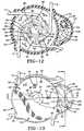
- Gear 56, bearing member 54 and hub 84form a reel 100 when snap-fitted together (FIG. 10) on which cables 5 are wound and unwound when ratchet member 4 is operated as described below.
- Bearing member 54lies in circular compartment 51 on front wall 62 with annular nub 75 sitting in bearing surface 64.
- Two cables 5are inserted into hub 84 of gear 56 with each enlarged end 88 of the cables secured in opposite openings 85 and with each end of the cables extending through opposite openings 70 oriented 90° with respect to the adjacent openings.
- Gear 56is latched to bearing member 54 as described above enclosing an open end of hub 84 and locking the cables therein.
- Pawl 52is placed in compartment 53 and bottom plate 58 sits on lip 66 and is secured to housing 50 enclosing compartments 51 and 53.
- Annular nub 101 of gear 56sits in bearing surface 71 of bottom plate 58 and along with annular nub 75 and bearing surface 64 allow gear 56 and bearing member 54 to rotate when cable 5 is dispensed from or collected on reel 100.
- ratchet member 4is placed against a side of package 2 (FIG. 1) so that bore 94 is exposed for receiving a seven-sided section 117 of a ratchet tool 115 (FIGS. 1 and 13).
- Fastener 7 and base 8are snap-fitted together (arrow A, FIG. 4) securing locking member 3 into a locked position and locking universal wrap 1 around package 2.
- Surface 117 of tool 115is inserted into multi-sided surface 95 and tool 115 is rotated to turn gear 56 and bearing member 54 in the direction of arrows B (FIG. 13).
- Catch 110 of pawl 52catches in teeth 80 of gear 56 as the gear is rotated, preventing reel 100 from rotating in a direction opposite to that of arrow B.
- Cables 5are tightened around package 2 and are collected on reel 100 as tool 115 is turned in the direction of arrows B. Tool 115 is turned until cables 5, locking member 3 and ratchet member 4 are firmly secured around and against package 2, thus preventing the removal of security device 1 from the package and preventing any unauthorized opening thereof.
- Universal wrap 1is removed by placing a key or unlocking tool 120 adjacent locking member 3 as shown by dot-dash lines in FIG. 15.
- Tool 120includes a base 122 with a pair of angled magnet support arms 121 on which are mounted permanent magnets 123.
- a support rib 124is formed on base 122 and extends upwardly therefrom and extends between arms 121 for properly positioning and guiding locking member 3 into position between magnets 123.
- the magnetic field of magnets 123causes metal tines 35 to move outwardly a sufficient distance to allow end 17 and particularly locking tabs 19 of fastener 7, to pass therethrough, thus allowing fastener 7 to be manually removed from its latched condition with base 8.
- cable 5is loose enough to allow device 1 to be removed from package 2.
- Five-sided section 118 of ratchet tool 115(FIG. 14) can then be inserted into five-sided opening 107 of pawl 52 after it has been removed from the package, and turned in the direction of arrow C (FIG. 12), releasing catch 110 from teeth 80 by compressing spring 108 against side wall 65, making reel 100 freewheeling, as shown by arrows D.
- a lockout tab 61which can be formed as a separate member or as a part of bottom plate 58, is pressed outwardly by a ramped end 109 of spring 108. As shown in FIGS.
- tab 61will have a multi-ramped bottom section which when engaged by ramped end 109 of spring 108 will engage the outer edge 109a of spring 108, moving tab 61 into an extended position above the peripheral edge 67 of side wall 65, as shown by dot-dash lines in FIG. 10. This then enables cables 5 to be freely unwound for placement about another package, after which multi-sided section 117 of tool 115 is used to rotate reel 100 and tighten cables 5 about a different package.
- Lockout tab 61is automatically released from ramped end 109 of spring 108 by placing member 3 against a package which pushes tab 61 inwardly disengaging spring 108 therefrom enabling spring 108 to return to its operative position, as shown in sold lines in FIGS. 10, 11 and 13, and move catch 110 into engagement with teeth 80. Universal wrap is then ready to be secured around the package as described above.
- security device 1is wrapped and secured around package 2, preventing the package from being opened.
- Cables 5extend through fastener 7 and base 8 of locking member 3 and the fastener and base are snap-fitted together.
- Metal tines 35lock under locking tabs 19 securing fastener 7 to base 8.
- Annular nubs 75 and 101sit in bearing surfaces 64 and 71, respectively, allowing bearing reel 100 to rotate freely within housing 50.
- catch 110 of pawl 52catches in teeth 80 of gear 56 allowing the reel to rotate in only one direction.
- seven-sided key 117 of tool 115rotates the reel tightening and securing cables 5 and thus universal wrap 1 around package 2.
- magnets 123 of unlocking tool 120cause metal tines 35 to deflect outwardly allowing fastener 7 to be dismantled from base 8 and further allowing security device 1 to be removed from package 2.
- Tool 115is used to disengage pawl 52 from teeth 80, as well as to tighten cables 5 about an object. Lockout device 61 also allows cables 5 to be wound and stored on the reel for future use of the security device.
- cables 5could be replaced with other flexible members made of plastic, chains, fibers, and similar materials, and will be covered by the term “cables” as used in the above description.
- locking member 3will be formed of a high-strength plastic material, with the exception of metal tines 35, thereby rendering it unaffected by moisture, chemicals and other harsh environments in which it may be used, and will prevent it from marring the objects on which it is mounted.
- ratchet member 4is constructed of a similar high-strength plastic material, providing similar advantages as those discussed above with respect to locking member 3.
- an electronic article surveillance tag (EAS) 112can be mounted on the rear surface of locking member 3, as shown in FIG. 1, or on the rear surface of ratchet member 4, when used in a retail store having an EAS security system at the exit, to prevent unauthorized removal of the package.
- security device 1can be used to securely retain a package or object in a closed position, as well as preventing its removal from a retail store having such EAS security systems.
- the improved security deviceis simplified, provides an effective, safe, inexpensive, and efficient device which achieves all the enumerated objectives, provides for eliminating difficulties encountered with prior devices, and solves problems and obtains new results in the art.
Landscapes
- Burglar Alarm Systems (AREA)
- Package Frames And Binding Bands (AREA)
- Clamps And Clips (AREA)
- Casings For Electric Apparatus (AREA)
Description
Claims (19)
- A security device (1) adapted to be placed about anobject (2) to prevent the object from being opened, saiddevice including:characterised in that the cable means (5) includes first and second cables for placement about the object to be secured,in thatcable means (5)placement about an object (2) to be secured;ratchet means (4) connected to the cable means (5) fortightening the cable means around the object; anda two-piece locking member (3) including a base (8) anda fastener (7), each piece being connected to the cablemeans, each of said pieces being releasably engaged witheach other for releasably locking said cable means (5) aboutthe object;said first cable extends between and is connected tothe ratchet means (4) and to the base (8) of the lockingmember, andin that the second cable extends between and is connectedto the ratchet means (4) and the fastener (8) of the lockingmember.
- A security device according to claim 1,characterisedin that the fastener (7) is releasably snap-fitted to thebase (8).
- A security device according to claim 2,characterisedin that the fastener (7) includes locking tabs (15, 16) andin that the base (8) includes metal tines (35) whichcooperate with the locking tabs (15, 16) of the fastener toreleasably secure the fastener (7) to the base (8).
- A security device according to claim 3,characterisedin that the device includes an unlocking tool (120) fordisengaging the metal tines (35) from the fastener and whichincludes magnets (123) for disengaging the metal tines (35)from the locking tabs (15, 16).
- A security device according to claim 4,characterisedin that the unlocking tool (120) includes a base part (122),a pair of permanent magnets (123) mounted in a spacedrelationship on the base part (122), and positioning means(124) for positioning the locking member (3) between thespaced magnets (123) for releasing the metal tines (35) fromthe locking tabs (15, 16).
- A security device according to claim 5,characterisedin that the positioning means comprises a rib (124) mountedon the base part (122) and extending between the spacedmagnets (123).
- A security device according to any one of claims 3 to6,characterised in that the base (8) includes a cover plate(44) which conceals the metal tines (35) within the base(8).
- A security device according to any one of claims 3 to7,characterised in that a guide rib (34) is mounted on thebase (8) of the locking member (3) and is slidablyengageable with the fastener (7) to assist in releasablysecuring the fastener to the base (8).
- A security device according to any one of thepreceding claims,characterised in that the ratchet means(4) includes a housing (50), a reel (100) rotatably mountedwithin said housing (50) for supporting the cable means (5),and a pawl (52) which operatively engages the reel (100) tolatch the reel (100) in a fixed position to maintain thecable means (5) tightened around the object.
- A security device according to claim 9,characterisedin that the reel (100) includes a hub (84) and spaced firstand second end flanges (56, 54), said first flange (56)having a plurality of teeth (80) formed around an outsideedge thereof.
- A security device according to claim 10,characterised in that a plurality of openings (85) areformed in the hub (84) for receiving enlarged ends (88) ofthe cable means (5) to secure said cable means to the hub(84).
- A security device according to any one of claims 9 to11,characterised in that the first and second cablesprovide four cable sections andin that each of said cablesections extends through an opening (70) formed in thehousing (50) substantially perpendicularly with respect tothe two adjacent cable sections.
- A security device according to any one of claims 9 to12,characterised in that the ratchet means (4) includes alock-out mechanism (61) for releasably securing the pawl(52) out of operative engagement with the reel (100).
- A security device according to claim 13,characterised in that the lock-out mechanism includes alock-out tab (61) movably mounted on the housing (50) andengageable by the pawl (52) upon the pawl being manuallymoved to a disengaged position from the reel (100) toreleasably secure the pawl in said disengaged position.
- A security device according to claim 14,characterised in that the a portion of the lock-out tab (61)extends outwardly beyond the housing (50) and is adapted tobe engaged by the object (2) when the ratchet means (4) isplaced on said object to move the lock-out tab (61) intoengagement with the pawl (52).
- A security device according to claim 15,characterised in that the pawl (52) includes a base member(105) with a resilient spring (108) and a catch (110)extending from said base member (105) andin that said catch(110) selectively engages the teeth (80) formed on the firstflange (56) of the reel (100) to provide for one-wayrotation of the reel (100) when engaged by said catch (110).
- A security device according to claim 16,characterised in that at least one of the spring (108) andlock-out tab (61) is formed with a ramped surface (109)which is slidably engaged by the other of said spring (108)and lock-out tab (61) to move the pawl catch (110) betweenengaged and disengaged positions with the reel (100).
- A security device according to any one of claims 9 to17,characterised in that it further includes a ratchet tool(115) andin that the pawl (52) is formed with an opening(107) having a multi-sided bore which is engaged by a multi-sidedfirst section (118) of the ratchet tool for movingsaid pawl (52) out of operative engagement with the reel(100).
- A security device according to claim 18,characterised in that the ratchet tool (115) includes amulti-sided second section (117) andin that the hub (84) isformed with a multi-sided bore (95) engageable with thesecond section (117) of the ratchet tool for rotating thereel to tighten the cable means (5) around the object.
Priority Applications (1)
| Application Number | Priority Date | Filing Date | Title |
|---|---|---|---|
| EP00123941AEP1101888B1 (en) | 1995-11-21 | 1996-05-06 | Universal wrap security device |
Applications Claiming Priority (3)
| Application Number | Priority Date | Filing Date | Title |
|---|---|---|---|
| US561370 | 1995-11-21 | ||
| US08/561,370US5722266A (en) | 1995-11-21 | 1995-11-21 | Universal wrap security device |
| PCT/US1996/006111WO1997019241A1 (en) | 1995-11-21 | 1996-05-06 | Universal wrap security device |
Related Child Applications (1)
| Application Number | Title | Priority Date | Filing Date |
|---|---|---|---|
| EP00123941ADivisionEP1101888B1 (en) | 1995-11-21 | 1996-05-06 | Universal wrap security device |
Publications (3)
| Publication Number | Publication Date |
|---|---|
| EP0862677A1 EP0862677A1 (en) | 1998-09-09 |
| EP0862677A4 EP0862677A4 (en) | 1999-01-20 |
| EP0862677B1true EP0862677B1 (en) | 2001-12-12 |
Family
ID=24241663
Family Applications (2)
| Application Number | Title | Priority Date | Filing Date |
|---|---|---|---|
| EP96913302AExpired - LifetimeEP0862677B1 (en) | 1995-11-21 | 1996-05-06 | Universal wrap security device |
| EP00123941AExpired - LifetimeEP1101888B1 (en) | 1995-11-21 | 1996-05-06 | Universal wrap security device |
Family Applications After (1)
| Application Number | Title | Priority Date | Filing Date |
|---|---|---|---|
| EP00123941AExpired - LifetimeEP1101888B1 (en) | 1995-11-21 | 1996-05-06 | Universal wrap security device |
Country Status (10)
| Country | Link |
|---|---|
| US (2) | US5722266A (en) |
| EP (2) | EP0862677B1 (en) |
| JP (1) | JP3953516B2 (en) |
| AU (2) | AU708423B2 (en) |
| BR (1) | BR9611740A (en) |
| CA (1) | CA2238042C (en) |
| DE (2) | DE69617999T2 (en) |
| HU (1) | HUP9901468A3 (en) |
| MX (1) | MX9803710A (en) |
| WO (1) | WO1997019241A1 (en) |
Families Citing this family (86)
| Publication number | Priority date | Publication date | Assignee | Title |
|---|---|---|---|---|
| US6092401A (en)* | 1999-02-18 | 2000-07-25 | Alpha Enterprises, Inc. | Electronic article surveillance security device |
| US6125669A (en)* | 1999-08-25 | 2000-10-03 | Kryptonite Corporation | Portable security frame for portable articles |
| US6298695B1 (en)* | 1999-12-06 | 2001-10-09 | Donald Vezina | Equipment security apparatus |
| US6167734B1 (en)* | 2000-01-10 | 2001-01-02 | Jay S Derman | Security cable coupling device |
| US6233985B1 (en)* | 2000-01-14 | 2001-05-22 | Fu-Chuan Huang | Coupling lock |
| US6164291A (en)* | 2000-03-02 | 2000-12-26 | Filippone; Thomas C. | Retracting hairholder device |
| US6427499B1 (en)* | 2000-10-05 | 2002-08-06 | Jay S Derman | Portable equipment security device |
| US6755055B2 (en) | 2002-02-26 | 2004-06-29 | Alpha Security Products, Inc. | Theft deterrent device |
| CA2465692A1 (en)* | 2003-05-02 | 2004-11-02 | Glen Walter Garner | Retractable coil unit for tags |
| DE10321687A1 (en)* | 2003-05-14 | 2004-12-02 | Checkpoint Systems International Gmbh | Method and device for securing objects by strapping |
| EP1870547B1 (en)* | 2006-06-21 | 2010-03-17 | MW Security AB | Security wrapper |
| US7518521B2 (en) | 2003-10-29 | 2009-04-14 | Display Technologies, Inc. | Rotating anti-theft tag |
| WO2005043494A1 (en)* | 2003-10-29 | 2005-05-12 | Display Technologies, Inc. | Anti-theft tag |
| CN2885757Y (en)* | 2005-08-09 | 2007-04-04 | 杭州中瑞思创科技有限公司 | Multifunctional binding device |
| US7243399B2 (en)* | 2004-11-19 | 2007-07-17 | Eric Liao | Wrapping device for packages |
| US8499595B2 (en)* | 2004-12-28 | 2013-08-06 | Checkpoint Systems, Inc. | Cable wrap security device |
| US7162899B2 (en) | 2004-12-28 | 2007-01-16 | Alpha Security Products, Inc. | Cable wrap security device |
| US7168275B2 (en) | 2004-12-28 | 2007-01-30 | Alpha Security Products, Inc. | Cable wrap security device |
| US7474209B2 (en) | 2005-01-14 | 2009-01-06 | Checkpoint Systems, Inc. | Cable alarm security device |
| US7292149B2 (en)* | 2005-03-16 | 2007-11-06 | Elpas Electro-Optic Systems, Ltd. | Electronic monitoring device |
| US7340926B2 (en)* | 2005-06-03 | 2008-03-11 | Kim Keun J | Restraint device |
| US7659817B2 (en)* | 2005-11-29 | 2010-02-09 | Checkpoint Systems, Inc. | Security device with perimeter alarm |
| US7403118B2 (en)* | 2005-11-29 | 2008-07-22 | Checkpoint Systems, Inc. | Security device with perimeter alarm |
| US20070131005A1 (en)* | 2005-12-14 | 2007-06-14 | Checkpoint Systems, Inc. | Systems and methods for providing universal security for items |
| US20070296545A1 (en)* | 2005-12-14 | 2007-12-27 | Checkpoint Systems, Inc. | System for management of ubiquitously deployed intelligent locks |
| US9404291B1 (en)* | 2015-03-04 | 2016-08-02 | Checkpoint Systems, Inc. | Device and method for an alarming strap tag |
| ATE461337T1 (en)* | 2006-06-21 | 2010-04-15 | Mw Security Ab | SAFETY PACKAGING |
| WO2007147798A1 (en)* | 2006-06-21 | 2007-12-27 | Mw Security Ab | Security wrapper |
| CH698863B1 (en)* | 2006-07-19 | 2009-11-30 | Pataco Ag Ind Und Unterhaltung | safety device |
| WO2008057740A2 (en)* | 2006-10-19 | 2008-05-15 | Adel Odeh Sayegh | Security tag with engaging element |
| FR2910994B1 (en)* | 2006-12-29 | 2009-04-17 | Edou Josquin Flaubert Obagha | ANTI-INTRUSION DEVICE FOR LUGGAGE |
| US7522048B2 (en)* | 2007-01-12 | 2009-04-21 | Checkpoint Systems, Inc. | Banding clip alarm |
| EP1970510A1 (en)* | 2007-03-13 | 2008-09-17 | MW Security AB | Security device |
| US9487970B2 (en) | 2007-03-28 | 2016-11-08 | Checkpoint Systems, Inc. | Cable wrap security device |
| US8122744B2 (en)* | 2007-03-28 | 2012-02-28 | Checkpoint Systems, Inc. | Cable wrap security device |
| US7992259B2 (en)* | 2007-04-13 | 2011-08-09 | Checkpoint Systems, Inc. | Tension reducer for cable wrap security device |
| EP2152991A1 (en)* | 2007-05-22 | 2010-02-17 | Pietro Necchi | Adjustable anti -theft device |
| US8087269B2 (en)* | 2008-02-07 | 2012-01-03 | Checkpoint Systems, Inc. | Cable wrap security device |
| US8305219B2 (en)* | 2008-02-22 | 2012-11-06 | Xiao Hui Yang | EAS tag using tape with conductive element |
| US8373565B2 (en) | 2008-02-22 | 2013-02-12 | Xiao Hui Yang | Security apparatus with conductive ribbons |
| US8274391B2 (en)* | 2008-02-22 | 2012-09-25 | Xiao Hui Yang | EAS tag using tape with conductive element |
| US8368542B2 (en)* | 2008-02-22 | 2013-02-05 | Xiao Hui Yang | EAS tag using tape with conductive element |
| US8368543B2 (en)* | 2008-02-22 | 2013-02-05 | Xiao Hui Yang | EAS tag with wrapping tethers and cover |
| US8373566B2 (en) | 2008-02-22 | 2013-02-12 | Xiao Hui Yang | Security apparatus with tether |
| US8228192B2 (en)* | 2008-05-30 | 2012-07-24 | Checkpoint Systems, Inc. | Cable lock closure with defeat prevention |
| SE533099C2 (en)* | 2008-07-22 | 2010-06-29 | Mw Security Ab | Security device with gripping means for enclosing an object to be protected |
| USD599693S1 (en) | 2008-08-27 | 2009-09-08 | Sayegh Adel O | Theft deterrent tag having crossing lanyard for use with articles |
| CN102439642A (en)* | 2009-03-12 | 2012-05-02 | 关卡系统公司 | Disposable cable lock and detachable alarm module |
| US8245371B2 (en)* | 2009-04-01 | 2012-08-21 | Chin Chu Chen | String securing device |
| USD628923S1 (en) | 2009-05-05 | 2010-12-14 | Universal Surveillance Corporation | Electronic article surveillance device having lanyards for use with articles |
| USD628924S1 (en) | 2009-05-05 | 2010-12-14 | Universal Surveillance Corporation | Theft deterrent tag having lanyards for use with articles |
| US9847003B2 (en) | 2009-06-01 | 2017-12-19 | USS Technologies, LLC | Cable alarm tag |
| US20110000811A1 (en)* | 2009-07-02 | 2011-01-06 | Dayan Maurice S | Clamshell package for holding and displaying consumer products |
| EP2496781A2 (en)* | 2009-11-02 | 2012-09-12 | Checkpoint Systems, Inc. | Adjustable dual loop cable security device |
| WO2011101873A1 (en) | 2010-02-16 | 2011-08-25 | Enneffe S.R.L. | Multi -function anti-theft system |
| US8640509B2 (en)* | 2010-04-30 | 2014-02-04 | Checkpoint Systems, Inc. | Security assembly for attachment to an object |
| US20120050042A1 (en)* | 2010-08-24 | 2012-03-01 | Checkpoint Systems, Inc. | Anti-theft security device |
| US8607601B1 (en)* | 2010-12-28 | 2013-12-17 | Launce Wickesberg | Lock |
| WO2012095874A1 (en) | 2011-01-11 | 2012-07-19 | Enneffe S.R.L. | Adjustable anti -theft device |
| US8917180B2 (en) | 2011-06-01 | 2014-12-23 | Universal Surveillance Corporation | Theft deterrent tag |
| US9328536B2 (en)* | 2011-06-20 | 2016-05-03 | Checkpoint Systems, Inc. | Multipurpose security device and associated methods |
| CN102956085A (en)* | 2011-08-17 | 2013-03-06 | 上海维恩佳得数码科技有限公司 | Anti-theft security device for binding strap |
| WO2013049481A1 (en)* | 2011-09-29 | 2013-04-04 | Invue Security Products Inc. | Cabinet lock for use with programmable electronic key |
| USD693257S1 (en) | 2011-12-08 | 2013-11-12 | Xiao Hui Yang | Electronic security apparatus with tether |
| US8938997B2 (en) | 2012-01-05 | 2015-01-27 | Checkpoint Systems, Inc. | Security surround device with cord lock |
| US20150287299A1 (en)* | 2012-01-31 | 2015-10-08 | Checkpoint Systems, Inc. | Security device with flexible strip |
| US8875427B2 (en) | 2012-03-30 | 2014-11-04 | Southern Imperial, Inc. | Rail including magnetic strip |
| US8596099B1 (en)* | 2012-11-02 | 2013-12-03 | HVAC Shackle LLC | HVAC theft deterrent apparatus and method |
| EP3071769B1 (en) | 2013-11-18 | 2019-04-10 | InVue Security Products, Inc. | Wrap for an item of merchandise |
| US9634386B2 (en) | 2015-01-19 | 2017-04-25 | Christopher C. Dundorf | Apparatus for safely securing radiation-transparent panels covering the antenna service bays of wireless telecommunication towers and methods of installing the same |
| US10226104B2 (en) | 2015-08-19 | 2019-03-12 | Nike, Inc. | Cord lock |
| US9805563B2 (en) | 2015-12-03 | 2017-10-31 | Checkpoint Systems, Inc. | Security device |
| US9934665B1 (en)* | 2016-09-16 | 2018-04-03 | Ningsheng Zhang | Box edge security device |
| CN106986100A (en)* | 2017-05-19 | 2017-07-28 | 赵元庆 | A kind of reusable intelligent environment protection Apparatus for strapping packages band |
| US20180340357A1 (en) | 2017-05-25 | 2018-11-29 | Invue Security Products Inc. | Package wrap |
| CN108033126B (en)* | 2017-12-30 | 2024-02-27 | 天津灵角创意科技有限公司 | Combined storage box with locking device |
| USD890618S1 (en) | 2018-02-27 | 2020-07-21 | Invue Security Products Inc. | Cable wrap |
| US10844638B2 (en)* | 2018-12-21 | 2020-11-24 | John Harris Sud | Retractable cable locking device |
| US10529207B1 (en) | 2019-01-08 | 2020-01-07 | Xiao Hui Yang | EAS device with elastic band |
| US11164434B2 (en) | 2020-02-25 | 2021-11-02 | Xiao Hui Yang | EAS device with elastic band |
| US11525284B2 (en)* | 2020-06-03 | 2022-12-13 | Brady Worldwide, Inc. | Panel door lockout |
| US12286817B2 (en)* | 2021-07-27 | 2025-04-29 | Patio Leash Llc | Retention patio leash for patio furniture |
| US12116807B2 (en)* | 2021-10-21 | 2024-10-15 | Rapitag Gmbh | Anti-theft device, in particular for cardboard boxes |
| CN116280596B (en)* | 2022-11-25 | 2023-11-14 | 江苏木道智能家居有限公司 | Transportation package suitable for wooden furniture |
| WO2024182904A1 (en)* | 2023-03-08 | 2024-09-12 | Crane Ryan | Parcel securement system |
| US12392172B2 (en)* | 2023-06-23 | 2025-08-19 | Industrial Security Solutions, Corp. | Spider wrap with integrated cable lock |
Family Cites Families (39)
| Publication number | Priority date | Publication date | Assignee | Title |
|---|---|---|---|---|
| US437548A (en)* | 1890-09-30 | Package-tie | ||
| US394739A (en)* | 1888-12-18 | Fastening for mail-matter and other packages | ||
| SE123470C1 (en)* | 1948-01-01 | |||
| US596237A (en)* | 1897-12-28 | Bicycle or tourist lock | ||
| US199468A (en)* | 1878-01-22 | Improvement in chain-locks for valises | ||
| US639196A (en)* | 1899-11-07 | 1899-12-12 | Paul Fehling | Bicycle-lock. |
| US673612A (en)* | 1900-02-13 | 1901-05-07 | Ernest L Appleby | Lock. |
| US886905A (en)* | 1907-04-20 | 1908-05-05 | Henry B Ward | Bundle or package tie. |
| US895403A (en)* | 1907-10-03 | 1908-08-04 | Henry C Wagner | Packet-tying device. |
| US1083612A (en)* | 1913-06-17 | 1914-01-06 | L A Prater | Bag-lock. |
| US1124130A (en)* | 1914-02-04 | 1915-01-05 | Arthur M Grant | Package and mail tying device. |
| US1141245A (en)* | 1914-07-07 | 1915-06-01 | Charles W Gillespie | Reeling device. |
| US1165320A (en)* | 1914-11-17 | 1915-12-21 | Irvin W Clary | Tier. |
| US1165816A (en)* | 1915-01-25 | 1915-12-28 | H C Otte | Cord-holder. |
| US1582444A (en)* | 1924-04-04 | 1926-04-27 | Bart Charles | Package seal |
| US1657190A (en)* | 1926-02-09 | 1928-01-24 | George C Ballou | Binding device |
| US2002946A (en)* | 1934-03-28 | 1935-05-28 | A J Donahue Corp | Buckle and process of making same |
| US3466668A (en)* | 1966-10-13 | 1969-09-16 | Yoriyasu Ochiai | Belt and buckle |
| US3395555A (en)* | 1967-06-07 | 1968-08-06 | Hickman Henry | Magnetic padlock |
| US3611760A (en)* | 1970-01-12 | 1971-10-12 | Muther Enterprises Inc | Locking device |
| US3831407A (en)* | 1972-12-26 | 1974-08-27 | L Coleman | Helmet guard |
| US3906758A (en)* | 1974-07-29 | 1975-09-23 | Ronald Hurwitt | Combination cable lock |
| US4086795A (en)* | 1976-02-26 | 1978-05-02 | The Firestone Tire & Rubber Company | Cable lock storage structure |
| DE2725580A1 (en)* | 1976-06-09 | 1977-12-22 | Lowe & Fletcher Ltd | Lock for holding suitcase |
| US4071023A (en)* | 1976-09-13 | 1978-01-31 | Gregory Peter J | Restraining device |
| US4418551A (en)* | 1981-07-06 | 1983-12-06 | Kochackis Donald G | Vending machine security cage |
| US4756171A (en)* | 1987-03-02 | 1988-07-12 | Homar Paul F | Luggage lock system |
| US4949679A (en)* | 1988-11-14 | 1990-08-21 | Wolfer Joseph A | Apparatus for securing an individual's hands adjacent his waist |
| US4896517A (en)* | 1989-07-14 | 1990-01-30 | Ling Chong Kuan | Wire lock having self-retractable wire |
| US4930324A (en)* | 1989-10-30 | 1990-06-05 | Illinois Tool Works, Inc. | Center-release, lockable buckle |
| US5144821A (en)* | 1991-03-28 | 1992-09-08 | Ernesti Robert M | Portable lid lock |
| US5156028A (en)* | 1991-04-08 | 1992-10-20 | Jiang Jy Chang | Padlock having a cable shackle and a locking means based on combination of numerals |
| GB9202074D0 (en)* | 1992-01-31 | 1992-03-18 | Oliver Keith A | Stock protection device |
| US5193368A (en)* | 1992-06-10 | 1993-03-16 | Ling Chong Kuan | Combination lock of strap buckle |
| US5345947A (en)* | 1993-07-26 | 1994-09-13 | Fisher David P | Wrist and ankle secured restraining device |
| US5379496A (en)* | 1993-07-27 | 1995-01-10 | American Cord & Webbing Co., Inc. | Cord release buckle |
| US5581853A (en)* | 1994-07-11 | 1996-12-10 | Miller; J. Daniel | Device for restraining prisoners in the compartment of an automobile |
| US5551447A (en)* | 1994-12-02 | 1996-09-03 | Hoffman; Andrew T. | Restraint belt |
| US5517836A (en)* | 1995-05-12 | 1996-05-21 | Hong; Chih-Cheng | Fastening device provided with a combination lock |
- 1995
- 1995-11-21USUS08/561,370patent/US5722266A/ennot_activeExpired - Lifetime
- 1996
- 1996-05-06CACA002238042Apatent/CA2238042C/ennot_activeExpired - Lifetime
- 1996-05-06JPJP51968297Apatent/JP3953516B2/ennot_activeExpired - Lifetime
- 1996-05-06BRBR9611740Apatent/BR9611740A/enactiveSearch and Examination
- 1996-05-06HUHU9901468Apatent/HUP9901468A3/enunknown
- 1996-05-06AUAU56351/96Apatent/AU708423B2/ennot_activeExpired
- 1996-05-06DEDE69617999Tpatent/DE69617999T2/ennot_activeExpired - Lifetime
- 1996-05-06EPEP96913302Apatent/EP0862677B1/ennot_activeExpired - Lifetime
- 1996-05-06WOPCT/US1996/006111patent/WO1997019241A1/enactiveIP Right Grant
- 1996-05-06EPEP00123941Apatent/EP1101888B1/ennot_activeExpired - Lifetime
- 1996-05-06DEDE69626874Tpatent/DE69626874T2/ennot_activeExpired - Lifetime
- 1997
- 1997-11-25USUS08/978,241patent/US5794464A/ennot_activeExpired - Lifetime
- 1998
- 1998-05-11MXMX9803710Apatent/MX9803710A/enunknown
- 1999
- 1999-09-28AUAU50198/99Apatent/AU727286B2/ennot_activeExpired
Also Published As
| Publication number | Publication date |
|---|---|
| CA2238042C (en) | 2006-04-04 |
| EP1101888B1 (en) | 2003-03-19 |
| WO1997019241A1 (en) | 1997-05-29 |
| EP0862677A1 (en) | 1998-09-09 |
| US5794464A (en) | 1998-08-18 |
| JP3953516B2 (en) | 2007-08-08 |
| EP1101888A1 (en) | 2001-05-23 |
| JP2000500543A (en) | 2000-01-18 |
| AU5019899A (en) | 1999-12-02 |
| DE69617999D1 (en) | 2002-01-24 |
| MX9803710A (en) | 1998-09-30 |
| CA2238042A1 (en) | 1997-05-29 |
| HUP9901468A3 (en) | 2001-09-28 |
| US5722266A (en) | 1998-03-03 |
| DE69617999T2 (en) | 2002-08-29 |
| DE69626874D1 (en) | 2003-04-24 |
| BR9611740A (en) | 1999-02-23 |
| AU727286B2 (en) | 2000-12-07 |
| AU708423B2 (en) | 1999-08-05 |
| DE69626874T2 (en) | 2003-12-24 |
| EP0862677A4 (en) | 1999-01-20 |
| AU5635196A (en) | 1997-06-11 |
| HUP9901468A2 (en) | 2001-06-28 |
Similar Documents
| Publication | Publication Date | Title |
|---|---|---|
| EP0862677B1 (en) | Universal wrap security device | |
| US7481086B2 (en) | Cable wrap security device | |
| US8122744B2 (en) | Cable wrap security device | |
| US9328536B2 (en) | Multipurpose security device and associated methods | |
| US7614265B2 (en) | Lockable storage container | |
| HK1141569A (en) | Cable wrap security device |
Legal Events
| Date | Code | Title | Description |
|---|---|---|---|
| PUAI | Public reference made under article 153(3) epc to a published international application that has entered the european phase | Free format text:ORIGINAL CODE: 0009012 | |
| 17P | Request for examination filed | Effective date:19980612 | |
| AK | Designated contracting states | Kind code of ref document:A1 Designated state(s):DE ES FR GB IT SE | |
| RIN1 | Information on inventor provided before grant (corrected) | Inventor name:ALFORD, WILLIAM G. Inventor name:MARSILIO, RONALD, M. Inventor name:GALLAGHER, CHRISTOPHER, G. Inventor name:WEISBURN, JAMES, T. Inventor name:YEAGER, LAWRENCE, R. | |
| A4 | Supplementary search report drawn up and despatched | Effective date:19981203 | |
| AK | Designated contracting states | Kind code of ref document:A4 Designated state(s):DE ES FR GB IT SE | |
| 17Q | First examination report despatched | Effective date:19991206 | |
| GRAG | Despatch of communication of intention to grant | Free format text:ORIGINAL CODE: EPIDOS AGRA | |
| RIN1 | Information on inventor provided before grant (corrected) | Inventor name:ALFORD, WILLIAM G. Inventor name:MARSILIO, RONALD, M. Inventor name:GALLAGHER, CHRISTOPHER, G. Inventor name:WEISBURN, JAMES, T. Inventor name:YEAGER, LAWRENCE, R. | |
| GRAG | Despatch of communication of intention to grant | Free format text:ORIGINAL CODE: EPIDOS AGRA | |
| GRAG | Despatch of communication of intention to grant | Free format text:ORIGINAL CODE: EPIDOS AGRA | |
| GRAH | Despatch of communication of intention to grant a patent | Free format text:ORIGINAL CODE: EPIDOS IGRA | |
| GRAH | Despatch of communication of intention to grant a patent | Free format text:ORIGINAL CODE: EPIDOS IGRA | |
| GRAA | (expected) grant | Free format text:ORIGINAL CODE: 0009210 | |
| AK | Designated contracting states | Kind code of ref document:B1 Designated state(s):DE ES FR GB IT SE | |
| PG25 | Lapsed in a contracting state [announced via postgrant information from national office to epo] | Ref country code:IT Free format text:LAPSE BECAUSE OF FAILURE TO SUBMIT A TRANSLATION OF THE DESCRIPTION OR TO PAY THE FEE WITHIN THE PRESCRIBED TIME-LIMIT;WARNING: LAPSES OF ITALIAN PATENTS WITH EFFECTIVE DATE BEFORE 2007 MAY HAVE OCCURRED AT ANY TIME BEFORE 2007. THE CORRECT EFFECTIVE DATE MAY BE DIFFERENT FROM THE ONE RECORDED. Effective date:20011212 | |
| REG | Reference to a national code | Ref country code:GB Ref legal event code:IF02 | |
| REF | Corresponds to: | Ref document number:69617999 Country of ref document:DE Date of ref document:20020124 | |
| PG25 | Lapsed in a contracting state [announced via postgrant information from national office to epo] | Ref country code:SE Free format text:LAPSE BECAUSE OF FAILURE TO SUBMIT A TRANSLATION OF THE DESCRIPTION OR TO PAY THE FEE WITHIN THE PRESCRIBED TIME-LIMIT Effective date:20020312 | |
| ET | Fr: translation filed | ||
| PG25 | Lapsed in a contracting state [announced via postgrant information from national office to epo] | Ref country code:ES Free format text:LAPSE BECAUSE OF FAILURE TO SUBMIT A TRANSLATION OF THE DESCRIPTION OR TO PAY THE FEE WITHIN THE PRESCRIBED TIME-LIMIT Effective date:20020627 | |
| PLBE | No opposition filed within time limit | Free format text:ORIGINAL CODE: 0009261 | |
| STAA | Information on the status of an ep patent application or granted ep patent | Free format text:STATUS: NO OPPOSITION FILED WITHIN TIME LIMIT | |
| 26N | No opposition filed | ||
| REG | Reference to a national code | Ref country code:GB Ref legal event code:732E | |
| REG | Reference to a national code | Ref country code:FR Ref legal event code:TP Ref country code:FR Ref legal event code:CD Ref country code:FR Ref legal event code:CA | |
| REG | Reference to a national code | Ref country code:FR Ref legal event code:PLFP Year of fee payment:20 | |
| PGFP | Annual fee paid to national office [announced via postgrant information from national office to epo] | Ref country code:DE Payment date:20150428 Year of fee payment:20 Ref country code:GB Payment date:20150506 Year of fee payment:20 | |
| PGFP | Annual fee paid to national office [announced via postgrant information from national office to epo] | Ref country code:FR Payment date:20150508 Year of fee payment:20 | |
| REG | Reference to a national code | Ref country code:DE Ref legal event code:R071 Ref document number:69617999 Country of ref document:DE | |
| REG | Reference to a national code | Ref country code:GB Ref legal event code:PE20 Expiry date:20160505 | |
| PG25 | Lapsed in a contracting state [announced via postgrant information from national office to epo] | Ref country code:GB Free format text:LAPSE BECAUSE OF EXPIRATION OF PROTECTION Effective date:20160505 |