EP0861633B1 - Bone anchoring device and insertion instrument - Google Patents
Bone anchoring device and insertion instrumentDownload PDFInfo
- Publication number
- EP0861633B1 EP0861633B1EP98400415AEP98400415AEP0861633B1EP 0861633 B1EP0861633 B1EP 0861633B1EP 98400415 AEP98400415 AEP 98400415AEP 98400415 AEP98400415 AEP 98400415AEP 0861633 B1EP0861633 B1EP 0861633B1
- Authority
- EP
- European Patent Office
- Prior art keywords
- thread
- handle
- wire
- shaft
- hole
- Prior art date
- Legal status (The legal status is an assumption and is not a legal conclusion. Google has not performed a legal analysis and makes no representation as to the accuracy of the status listed.)
- Expired - Lifetime
Links
- 210000000988bone and boneAnatomy0.000titleclaimsabstractdescription31
- 238000004873anchoringMethods0.000titleclaimsdescription23
- 230000037431insertionEffects0.000title1
- 238000003780insertionMethods0.000title1
- 238000001356surgical procedureMethods0.000claimsdescription9
- 230000000399orthopedic effectEffects0.000claimsdescription2
- 239000000463materialSubstances0.000description9
- 210000002435tendonAnatomy0.000description6
- 235000012431wafersNutrition0.000description6
- 238000009434installationMethods0.000description5
- 238000000034methodMethods0.000description5
- 238000005553drillingMethods0.000description4
- 210000003041ligamentAnatomy0.000description4
- 206010028980NeoplasmDiseases0.000description2
- 239000004952PolyamideSubstances0.000description2
- 210000003423ankleAnatomy0.000description2
- 230000000903blocking effectEffects0.000description2
- 230000006835compressionEffects0.000description2
- 238000007906compressionMethods0.000description2
- 229920002647polyamidePolymers0.000description2
- 229920000728polyesterPolymers0.000description2
- 230000002787reinforcementEffects0.000description2
- 241001494479PecoraSpecies0.000description1
- 230000002009allergenic effectEffects0.000description1
- 230000015572biosynthetic processEffects0.000description1
- 230000000711cancerogenic effectEffects0.000description1
- 231100000315carcinogenicToxicity0.000description1
- 210000003679cervix uteriAnatomy0.000description1
- 239000000470constituentSubstances0.000description1
- 230000001054cortical effectEffects0.000description1
- 230000003247decreasing effectEffects0.000description1
- 238000006073displacement reactionMethods0.000description1
- 238000000605extractionMethods0.000description1
- 210000003414extremityAnatomy0.000description1
- 239000004744fabricSubstances0.000description1
- 208000014674injuryDiseases0.000description1
- 229910052741iridiumInorganic materials0.000description1
- GKOZUEZYRPOHIO-UHFFFAOYSA-Niridium atomChemical compound[Ir]GKOZUEZYRPOHIO-UHFFFAOYSA-N0.000description1
- 238000012423maintenanceMethods0.000description1
- 210000000056organAnatomy0.000description1
- 239000004033plasticSubstances0.000description1
- 229920006149polyester-amide block copolymerPolymers0.000description1
- 229920001296polysiloxanePolymers0.000description1
- 230000002035prolonged effectEffects0.000description1
- 239000000941radioactive substanceSubstances0.000description1
- 238000010079rubber tappingMethods0.000description1
- 239000000725suspensionSubstances0.000description1
- 230000009466transformationEffects0.000description1
- 230000008733traumaEffects0.000description1
- 210000000689upper legAnatomy0.000description1
- 210000004291uterusAnatomy0.000description1
Images


Classifications
- A—HUMAN NECESSITIES
- A61—MEDICAL OR VETERINARY SCIENCE; HYGIENE
- A61B—DIAGNOSIS; SURGERY; IDENTIFICATION
- A61B17/00—Surgical instruments, devices or methods
- A61B17/04—Surgical instruments, devices or methods for suturing wounds; Holders or packages for needles or suture materials
- A61B17/0401—Suture anchors, buttons or pledgets, i.e. means for attaching sutures to bone, cartilage or soft tissue; Instruments for applying or removing suture anchors
- A61B2017/0406—Pledgets
- A—HUMAN NECESSITIES
- A61—MEDICAL OR VETERINARY SCIENCE; HYGIENE
- A61B—DIAGNOSIS; SURGERY; IDENTIFICATION
- A61B17/00—Surgical instruments, devices or methods
- A61B17/04—Surgical instruments, devices or methods for suturing wounds; Holders or packages for needles or suture materials
- A61B17/0401—Suture anchors, buttons or pledgets, i.e. means for attaching sutures to bone, cartilage or soft tissue; Instruments for applying or removing suture anchors
- A61B2017/0409—Instruments for applying suture anchors
- A—HUMAN NECESSITIES
- A61—MEDICAL OR VETERINARY SCIENCE; HYGIENE
- A61B—DIAGNOSIS; SURGERY; IDENTIFICATION
- A61B17/00—Surgical instruments, devices or methods
- A61B17/04—Surgical instruments, devices or methods for suturing wounds; Holders or packages for needles or suture materials
- A61B17/0401—Suture anchors, buttons or pledgets, i.e. means for attaching sutures to bone, cartilage or soft tissue; Instruments for applying or removing suture anchors
- A61B2017/0446—Means for attaching and blocking the suture in the suture anchor
- A61B2017/0458—Longitudinal through hole, e.g. suture blocked by a distal suture knot
- A—HUMAN NECESSITIES
- A61—MEDICAL OR VETERINARY SCIENCE; HYGIENE
- A61B—DIAGNOSIS; SURGERY; IDENTIFICATION
- A61B17/00—Surgical instruments, devices or methods
- A61B17/04—Surgical instruments, devices or methods for suturing wounds; Holders or packages for needles or suture materials
- A61B17/0469—Suturing instruments for use in minimally invasive surgery, e.g. endoscopic surgery
- A61B2017/0475—Suturing instruments for use in minimally invasive surgery, e.g. endoscopic surgery using sutures having a slip knot
- A—HUMAN NECESSITIES
- A61—MEDICAL OR VETERINARY SCIENCE; HYGIENE
- A61B—DIAGNOSIS; SURGERY; IDENTIFICATION
- A61B17/00—Surgical instruments, devices or methods
- A61B17/04—Surgical instruments, devices or methods for suturing wounds; Holders or packages for needles or suture materials
- A61B2017/0496—Surgical instruments, devices or methods for suturing wounds; Holders or packages for needles or suture materials for tensioning sutures
Definitions
- the present inventionrelates to a surgical device bone anchor, and more particularly a device surgical method for performing suture anchorage or surgical wire on a bone support, especially in orthopedic, traumatological, gynecological and carcinological.
- tendons or ligamentsThe rupture of tendons or ligaments is an accident which can occur in many individuals of all ages, active or inactive, as a result of trauma or excessive effort important.
- surgerymay be performed either in open surgery or in closed surgery using laparoscopic or arthroscopic procedures.
- Surgical techniques using such devicesare described, for example, by FA Barber et al., J. of Arthroscopy and Related Surgery, vol. 11, No. 1, p. 21-28 (1995).
- WO 95.32669discloses a device referred to as "knot push" for suture, comprising a rod sliding in a tube whose distal end partially open, the whole being maneuvered by a pusher secured to the rod and a support plate.
- the present inventionrelates to an anchoring device bone requiring prior drilling of a single hole any wall, without requiring tapping, and allowing the fixation of organs such as tendons and ligaments, or suspension of the cervix, using a surgical wire or a suture without the need to use a means of the screw or piton type.
- the inventionalso relates to ancillary equipment specially adapted for setting up the anchoring device supra.
- the anchoring device according to the present inventioncan be used in combination with a hole drilled in the bone support, and is constituted by a wire comprising a middle part intended to be introduced into the drilled hole at prerequisite, having a loop shape closed by a knot flowing, covering the looped portion an envelope or deformable tubular sheath capable of sliding on the wire in the limits of the loop.
- the thread usedis a surgical wire or suture, absorbable or non-absorbable, made for example of polyester such as Ercylene® or polyamide such as Trynil®.
- the envelope or tubular sheath slidable on the yarn in the loopis of a lower total length or equal to twice the depth of drilling in the bone and a diameter less than or equal to that of the hole drilled in the bone.
- the loop carrying the sheathis fully introduced in the hole drilled in the bone.
- This sheathcan advantageously be made of any deformable material, and presenting preferably some elasticity, having the property of being implantable, resorbable or non-absorbable (eg a wire or plastic braided, a tube of polyester or polyamide, or a silicone tube).
- the sheathmay consist of a single element or several elements.
- the ends of the sheathcan be in abutment against the knot flowing, but they can also be at a distance of it, the only condition being that the wire, when the knot tightens, comes to apply against the sheath and cause it to deform.
- the sheath linear cylinder shapeis threaded onto the wire and then the loop is formed around the sheath.
- the wall of the sheathis pierced in the middle by an orifice through which pass the two strands of the wire.
- the wireenters the sheath by its middle, comes out first by one end, forms a loop and returns to the other end of the sheath and spring through the hole made in the middle of the sheath.
- the sheathis in the form of an O-ring presenting at least one orifice passing through its wall for the passage of two strands of the wire.
- the wireenters the sheath through the hole, forms a loop following the inside of the annular sheath and spring through the same hole.
- the sheathis preferably reinforced in the area where penetrates the wire, that is to say on the periphery of each of its extremities, or around the orifice made in its wall, where appropriate.
- This reinforcementcan be obtained for example by providing extra material thickness or by fixing sticking a band with a greater resistance.
- the ancillary for setting up the anchoring devicecomprises a handle comprising at one end a point likely to carry the loop of wire and be introduced into the hole drilled in the bone, and to the other end a handle of manipulation by the user, as well as at least one solidarity wire holder of the sleeve and carrying the ends of the wire.
- the handlecan slide longitudinally with respect to the handle on a limited distance by at least one stop, and the handle or the handle has means for blocking their position relative as long as a predetermined traction force is not applied on the handle or handle.
- the ancillaryincludes two wire holders, each being constituted by a plate disposed on the handle, the two plates located on both sides of the axis of the sleeve, and being able to slide on the handle following a different distance from each other.
- the plate that can slide over the longest distanceis fixed the end of the strand of the wire carrying the noose, while the end of the other strand of the wire, which carries not the noose, is attached to the fixed plate or lower sliding.
- the use of the ancillary for the implementation of the anchoring device of the inventionis easily done in introducing the tip of the ancillary, carrying the loop and its sheath, in the hole previously drilled in the bone, up to what the loop is totally engaged in the hole. After remove the tip from the hole while leaving the wire behind and the sheath, it is enough then to exert a traction on the strand of the wire not carrying the noose, while braking slightly the other strand, to cause the tightening of the loop inside the hole in the bone and the deformation of the sheath on the buckle up to take the shape of a ball whose the diameter is greater than that of the front tubular sheath deformation. The traction being prolonged until the blocking, the deformed sheath is then in compression against the internal walls of the cavity.
- the device and the ancillary pose according to the present inventionare particularly intended for repair surgery of ligaments and tendons.
- the inventioncan also be used in gynecology, for example to fix the uterus on the sacrum through a ligament.
- the device of the inventionis still suitable for surgery carcinological, and in this application we use a wire that may contain a radioactive substance such as iridium.
- the threadis placed in the tumor, and using preferably a nonabsorbable wire, the latter can serve as a benchmark for secondary removal of the tumor.
- the anchoring device of the present inventioncomprises a suture (1) forming in its middle part a closed loop (2) by a knot flowing (3) can be tightened by simply pulling on one of the two strands (4, 5) of the wire (1).
- the wire (1)is wrapped by a sheath (6), deformable and compressible, capable of sliding On the string.
- Pulling on the strand (4) of the yarncauses a decreasing the length of the loop (2) until its length becomes equal to that of the sheath (6).
- Continuing pulling on the strand (4) of the wire (1)one causes on the one hand a compression of the sheath whose surface forms ripples because of the compressibility of the material that constitutes, and on the other hand the tightening of the knot (3).
- Edges of the sheath, at each of its ends (7) and (8),are reinforced to prevent them from being cut by the wire of suture when it is tight. This reinforcement is obtained here by a mere extra thickness of material.
- the deviceis put in place by means of a ancillary equipment as described below.
- the method of implementationconsists in introducing the loop (2) carrying the sheath (6) in the hole drilled in the bone, then to tighten by exerting a pull on the strand (4) of the wire (1). It is preferable to introduce the entire loop into the hole as well as the noose (3).
- This ancillaryincludes a tip (9) for supporting the loop of the suture (1) to ensure its place in the hole drilled in the bone (not shown).
- This tip (9)is fixed on a handle (10) integral with a handle (11).
- On the handle (10) near the handle (11)are arranged two plates (12a) and (12b) on which both ends of the suture (1) are placed to facilitate their manipulation by the user.
- the tip (9) carrying the wire (1) formed in buckle carrying its sheath (6), in the holewe undo the strands (4) and (5) of the wire (1) fixed on the wafers (12a) and (12b).
- We remove the ancillary holeby acting on the handle (11), then pulling on the strand (4) of the wire (1) of slip the slip knot (3) and deform the sheath (6) to form a ball.
- the ancillary shown in Figure 3has a tip (9), a handle (10), a handle (11) and pads (12a) and (12b) identical to those in Figure 2, but the handle and the pads can move axially through report to the handle.
- a pin (13) removablecan block both wire plates (12a) and (12b) while the handle is held in place on the sleeve by simply snapping.
- the handle (10)is split by a groove (14) which allows the moving the pads when the pin (13) is removed.
- This groove (14)is longer on the side of the plate (12b) than on the side of the wafer (12a) so as to limit the movement of platelets in a different way, as shown below, the translational motion of the plate (12b) which can be carried out over a longer distance longer than that of the wafer (12a). So, the strand of the wire forming the knot is attached to the wafer whose movement is Most important.
- the groove (14)is enlarged in the part (15) receiving the handle.
- This enlarged part (15) of the groovehas a stop (16) and is limited by the two shoulders (17) and (18) formed on each half of the neck. This stop and these shoulders are intended to cooperate with two lugs (19) and (20) provided on the axis (21) of the handle (11).
- the head of the lug (19)is of triangular shape, the tip being directed towards the bottom of the groove (14) while that its base is directed towards the handle (11).
- the lug (20)has a hexagonal shaped head. In this way, when the handle is pulled with sufficient force (11) previously put in place on the handle (10), the lug (20), because of its shape, can pass on the stop (17) by spreading the two branches of the handle (10) on either side of the groove (14), the displacement being limited by the lug (19) whose base comes against the stop (16). In this position, the lug (20) has protruded from the shoulder (17).
- This movement of the handle (11) relative to the handle (10)can only be carried out by exerting a traction force predetermined on the handle, so as to overcome the resistance of the abutment (17) against one of the hexagonal faces of the pin (20) and to force the spacing of the two branches of the handle on both sides of the groove (14). So, a low traction on the handle (11) drives the handle (10) with the handle, while a stronger pull disengages the handle of the handle.
- the anchoring deviceis first introduced into a hole drilled beforehand into the bone.
- the loop closed bearing flexible sheathis placed on the tip (9) and the ends of the suture are attached to the wire plates (12a) and (12b) as in the example preceding, the two strands of the wire being stretched between the tip and each wafer.
- the point carrying the wireis introduced into the drilled hole in the bone and the pin (13) is removed in order to release the two plates that can slide on the handle (10).
- the userexerts a slight pull on the handle, which causes the removal of the tip of the hole, the handle and the sleeve remaining solidary.
- the loop, its sheath and the knotstay in the hole, because of the forces friction.
- plateletscan slide on the handle (10)
- the plate (12a)will come into support against the bottom of the groove (14) and will stretch the strand (4). This will cause the tightening of the knot (3) and the deformation from the sheath (6) until it forms a ball.
- FIG. 5 and 6Ancillary equipment including the two constituent elements are shown in Figures 5 and 6 is intended for a automatic installation of the anchoring device of the invention, the user can in this case manipulate the ancillary with one hand.
- the element of Figure 5is a support receiving that of Figure 6.
- the latteris similar to ancillary equipment of Figure 3, the handle (11) being replaced by a pusher (22).
- the support element of Figure 5includes a support semi-cylindrical (23) for receiving the handle (10) of the element of Figure 6. To ensure proper maintenance of the handle, this support is closed in its distal portion (24). So the establishment of the other element is done by introducing the end of the handle (10) carrying the tip (9) in the open part of the support (23) and dragging it into the closed part (24) until the pusher (22) comes between the two abutments (25) and (26) integral with the support.
- the portion (28) of the support carrying the stops (25) and (26)can slide on the axis (27), the sliding movement being effected by acting on the handle (29) secured to the support (28) and on the handle (30) secured to the shaft (27) (both handles are held apart by a non-spring represent).
- the end of the shaft (27)is integral with the part (31) of the support carrying the open tube (23).
- the userenters the ancillary, including both elements of Figures 5 and 6 assembled by the two handles (29) and (30) with one hand, it engages the point (9) carrying the loop and the sheath into the hole previously drilled in the bone, then he removes the pin (13) thus releasing the handles (29) and (30).
- the usermust continue to tighten the handles until that the pusher (22) breaks at the level of its narrowing. This indicates to the user that he has exerted the necessary force the installation of the anchoring system.
- Figure 7shows explicitly the position of the wire of suture (1) in a closed loop and carrying the flexible sheath (3) placed on the tip (9) at the end of the handle (10) of the ancillary pose.
Landscapes
- Health & Medical Sciences (AREA)
- Surgery (AREA)
- Life Sciences & Earth Sciences (AREA)
- Medical Informatics (AREA)
- Nuclear Medicine, Radiotherapy & Molecular Imaging (AREA)
- Engineering & Computer Science (AREA)
- Biomedical Technology (AREA)
- Heart & Thoracic Surgery (AREA)
- Rheumatology (AREA)
- Molecular Biology (AREA)
- Animal Behavior & Ethology (AREA)
- General Health & Medical Sciences (AREA)
- Public Health (AREA)
- Veterinary Medicine (AREA)
- Surgical Instruments (AREA)
- Prostheses (AREA)
Abstract
Description
Translated fromFrenchLa présente invention concerne un dispositif chirurgicald'ancrage osseux, et plus particulièrement un dispositifchirurgical permettant de réaliser un ancrage de fil de sutureou de fil chirurgical sur un support osseux, notamment enchirurgie orthopédique, traumatologique, gynécologique etcarcinologique.The present invention relates to a surgical devicebone anchor, and more particularly a devicesurgical method for performing suture anchorageor surgical wire on a bone support, especially inorthopedic, traumatological, gynecological andcarcinological.
La rupture de tendons ou de ligaments est un accident quipeut survenir chez de nombreux individus de tous âges, actifsou inactifs, à la suite de traumatismes ou d'efforts tropimportants. Les techniques chirurgicales réparatrices courammentemployées consistent à attacher le tendon, au moyen d'unfil de suture, à une vis, une cheville ou un piton fixé dansl'os voisin.The rupture of tendons or ligaments is an accident whichcan occur in many individuals of all ages, activeor inactive, as a result of trauma or excessive effortimportant. Surgical techniques commonly repairingused to attach the tendon, by means of asuture, to a screw, ankle or a peg set inthe neighbor bone.
Pour cela, il est généralement nécessaire de forer dansl'os un trou et d'y visser une vis ou un piton, ou un trou nontaraudé recevant une cheville pouvant se bloquer dans l'os,qui sert de moyen d'ancrage sur lequel on attache ensuite unfil de suture qui est utilisé pour rattacher le tendon qui aété arraché de son support osseux. Suivant d'autres techniques,après avoir foré un trou adapté à recevoir un pitond'ancrage, on fait passer le fil de suture dans le chas dupiton d'ancrage, puis on introduit celui-ci dans le trou aumoyen d'un appareillage spécial, et enfin on suture le tendonà fixer. Un exemple de vis d'ancrage pour fixation de tissusau moyen d'un fil de suture est décrit dans le brevet US-A-5.443.482.For this, it is usually necessary to drill inthe bone a hole and screw in a screw or a stud, or a hole notapped receiving an ankle that can become stuck in the bone,which serves as a means of anchoring to which we then attach asuture that is used to reattach the tendon that hasbeen torn from his bone support. Following other techniques,after having drilled a hole adapted to receive a peakanchoring, the suture is passed through the eye of theanchor bolt, then we introduce it into the hole atspecial equipment, and finally suture the tendonto fix. An example of an anchoring screw for fastening fabricsby means of a suture is described in US-A-5,443,482.
Selon les cas, les interventions peuvent être effectuéessoit en chirurgie à ciel ouvert, soit en chirurgie à cielfermé au moyen de procédés coelioscopiques ou arthroscopiques.Des techniques chirurgicales utilisant des dispositifs de cegenre sont décrites par exemple par F. A. Barber et al.,J. ofArthroscopy and Related Surgery, vol. 11, n° 1, p. 21-28(1995).Depending on the case, surgery may be performed either in open surgery or in closed surgery using laparoscopic or arthroscopic procedures. Surgical techniques using such devices are described, for example, by FA Barber et al.,J. ofArthroscopy and Related Surgery, vol. 11, No. 1, p. 21-28 (1995).
Ces dispositifs connus présentent l'inconvénient d'êtretrès invasifs, non résorbables, et de requérir des techniquesde mise en place souvent délicates à mettre en oeuvre; deplus certains produits qui y sont utilisés contiennent desmatériaux allergisants, par exemple certains matériaux àmémoire de forme et parfois même cancérigènes, selon certainsauteurs. En outre, un grand nombre de vis, de chevilles ou depitons, et d'accessoires de forage de l'os et de mise en placedu moyen d'ancrage, doivent être disponibles dans des dimensionsdiverses pour pouvoir répondre à toutes les situations.These known devices have the disadvantage of beingvery invasive, non-absorbable, and require techniquesset-up often difficult to implement; ofplus some products that are used containallergenic materials, for example certain materials toshape memory and sometimes even carcinogenic, according to someauthors. In addition, a large number of screws, dowels orpitons, and accessories drilling the bone and setting upof the anchoring means, must be available invarious to be able to respond to all situations.
Dans un autre domaine, la demande WO 95.32669 décrit undispositif dénommé "pousse-noeud" pour fil de suture, comprenantune tige coulissant dans un tube dont l'extrémité distaleest partiellement ouverte, l'ensemble étant manoeuvré par unpoussoir solidaire de la tige et d'une plaque d'appui.In another field, the application WO 95.32669 discloses adevice referred to as "knot push" for suture, comprisinga rod sliding in a tube whose distal endpartially open, the whole being maneuvered by apusher secured to the rod and a support plate.
La présente invention a pour objet un dispositif d'ancrageosseux nécessitant le forage préalable d'un simple trouà paroi quelconque, sans requérir de taraudage, et permettantla fixation d'organes tels que des tendons et des ligaments,ou la suspension du col de l'utérus, au moyen d'un fil chirurgicalou d'un fil de suture sans qu'il soit nécessaire d'utiliserun moyen du type vis ou piton.The present invention relates to an anchoring devicebone requiring prior drilling of a single holeany wall, without requiring tapping, and allowingthe fixation of organs such as tendons and ligaments,or suspension of the cervix, using a surgical wireor a suture without the need to usea means of the screw or piton type.
L'invention a également pour objet un matériel ancillairespécialement adapté à la mise en place du dispositif d'ancrageprécité.The invention also relates to ancillary equipmentspecially adapted for setting up the anchoring devicesupra.
Le dispositif d'ancrage conforme à la présente inventionest utilisable en combinaison avec un trou foré dans lesupport osseux, et est constitué par un fil comprenant unepartie médiane destinée à être introduite dans le trou foré aupréalable, présentant une forme de boucle fermée par un noeudcoulant, portant sur la partie en boucle une enveloppe ougaine tubulaire déformable pouvant coulisser sur le fil dansles limites de la boucle.The anchoring device according to the present inventioncan be used in combination with a hole drilled in thebone support, and is constituted by a wire comprising amiddle part intended to be introduced into the drilled hole atprerequisite, having a loop shape closed by a knotflowing, covering the looped portion an envelope ordeformable tubular sheath capable of sliding on the wire inthe limits of the loop.
Suivant une forme préférentielle de réalisation, le filutilisé est un fil chirurgical ou un fil de suture, résorbableou non résorbable, réalisé par exemple en polyester tel que leErcylène® ou en polyamide tel que le Trynil®.According to a preferred embodiment, the threadused is a surgical wire or suture, absorbableor non-absorbable, made for example of polyester such asErcylene® or polyamide such as Trynil®.
L'enveloppe ou gaine tubulaire pouvant coulisser sur lefil dans la boucle est d'une longueur totale inférieure ouégale au double de la profondeur du perçage dans l'os et d'undiamètre inférieur ou égal à celui du trou foré dans l'os.Ainsi, la boucle portant la gaine est entièrement introduitedans le trou foré dans l'os. Cette gaine peut avantageusementêtre réalisée en tous matériaux déformables, et présentant depréférence une certaine élasticité, ayant la propriété d'êtreimplantables, résorbables ou non résorbables (par exemple unfil métallique ou plastique tressé, un tube en polyester ou enpolyamide, ou un tube en silicone).The envelope or tubular sheath slidable on theyarn in the loop is of a lower total length orequal to twice the depth of drilling in the bone and adiameter less than or equal to that of the hole drilled in the bone.Thus, the loop carrying the sheath is fully introducedin the hole drilled in the bone. This sheath can advantageouslybe made of any deformable material, and presentingpreferably some elasticity, having the property of beingimplantable, resorbable or non-absorbable (eg awire or plastic braided, a tube of polyester orpolyamide, or a silicone tube).
Selon les cas, la gaine peut être constituée par un seulélément ou plusieurs éléments. Lors de la mise en place, lesextrémités de la gaine peuvent être en butée contre le noeudcoulant, mais ils peuvent aussi être à une certaine distancede celui-ci, la seule condition étant que le fil, lorsque lenoeud se resserre, vienne s'appliquer contre la gaine etprovoquer sa déformation.Depending on the case, the sheath may consist of a singleelement or several elements. When setting up, theends of the sheath can be in abutment against the knotflowing, but they can also be at a distanceof it, the only condition being that the wire, when theknot tightens, comes to apply against the sheath andcause it to deform.
Suivant une forme simple de réalisation, la gaine enforme de cylindre linéaire est enfilée sur le fil, puis laboucle est formée autour de la gaine.According to a simple embodiment, the sheathlinear cylinder shape is threaded onto the wire and then theloop is formed around the sheath.
Suivant une variante conforme à l'invention, la paroi dela gaine est percée en son milieu par un orifice par lequelpassent les deux brins du fil. Ainsi, le fil pénètre dans lagaine par son milieu, en sort une première fois par une extrémité,forme une boucle et rentre à nouveau par l'autre extrémité de la gaine et ressort par l'orifice pratiqué dans lemilieu de la gaine.According to a variant according to the invention, the wall ofthe sheath is pierced in the middle by an orifice through whichpass the two strands of the wire. Thus, the wire enters thesheath by its middle, comes out first by one end,forms a loop and returns to the other endof the sheath and spring through the hole made in themiddle of the sheath.
Suivant une autre forme de réalisation de l'invention, lagaine se présente sous la forme d'un anneau torique présentantau moins un orifice traversant sa paroi pour le passage desdeux brins du fil. Dans cette variante, le fil pénètre dans lagaine par l'orifice, forme une boucle en suivant l'intérieurde la gaine annulaire et ressort par le même orifice.According to another embodiment of the invention, thesheath is in the form of an O-ring presentingat least one orifice passing through its wall for the passage oftwo strands of the wire. In this variant, the wire enters thesheath through the hole, forms a loop following the insideof the annular sheath and spring through the same hole.
La gaine est de préférence renforcée dans la zone oùpénètre le fil, c'est-à-dire sur la périphérie de chacune deses extrémités, ou autour de l'orifice pratiqué dans sa paroi,le cas échéant. Ce renforcement peut être obtenu par exempleen prévoyant une surépaisseur de matière ou en fixant parcollage une bande présentant une résistance plus grande.The sheath is preferably reinforced in the area wherepenetrates the wire, that is to say on the periphery of each ofits extremities, or around the orifice made in its wall,where appropriate. This reinforcement can be obtained for exampleby providing extra material thickness or by fixingsticking a band with a greater resistance.
L'ancillaire de mise en place du dispositif d'ancrageconforme à la présente invention comprend un manche comportantà une extrémité une pointe susceptible de porter la boucle dufil et d'être introduite dans le trou foré dans l'os, et àl'autre extrémité une poignée de manipulation par l'utilisateur,ainsi que au moins un support porte-fil solidaire dumanche et portant les extrémités du fil.The ancillary for setting up the anchoring deviceaccording to the present invention comprises a handle comprisingat one end a point likely to carry the loop ofwire and be introduced into the hole drilled in the bone, and tothe other end a handle of manipulation by the user,as well as at least one solidarity wire holder of thesleeve and carrying the ends of the wire.
Suivant une forme préférentielle de réalisation, lapoignée peut coulisser longitudinalement par rapport au manchesur une distance limitée par au moins une butée, et le mancheou la poignée comporte des moyens pour bloquer leur positionrelative tant qu'une force prédéterminée de traction n'est pasappliquée sur la poignée ou sur le manche.According to a preferred embodiment, thehandle can slide longitudinally with respect to the handleon a limited distance by at least one stop, and the handleor the handle has means for blocking their positionrelative as long as a predetermined traction force is notapplied on the handle or handle.
Suivant une autre caractéristique de la présente invention,l'ancillaire comprend deux supports porte-fil, chacunétant constitué par une plaquette disposée sur le manche, lesdeux plaquettes se trouvant de part et d'autre de l'axe du manche, et étant susceptibles de coulisser sur le manchesuivant une distance différente l'une de l'autre. Sur laplaquette pouvant coulisser sur la plus grande distance estfixée l'extrémité du brin du fil portant le noeud coulant,tandis que l'extrémité de l'autre brin du fil, qui ne portepas le noeud coulant, est rattachée à la plaquette fixe ou deplus faible coulissement.According to another characteristic of the present invention,the ancillary includes two wire holders, eachbeing constituted by a plate disposed on the handle, thetwo plates located on both sides of the axis of thesleeve, and being able to slide on the handlefollowing a different distance from each other. On theplate that can slide over the longest distance isfixed the end of the strand of the wire carrying the noose,while the end of the other strand of the wire, which carriesnot the noose, is attached to the fixed plate orlower sliding.
L'utilisation de l'ancillaire pour la mise en place dudispositif d'ancrage de l'invention se fait facilement enintroduisant la pointe de l'ancillaire, portant la boucle etsa gaine, dans le trou préalablement foré dans l'os, jusqu'àce que la boucle soit totalement engagées dans le trou. Aprèsavoir retiré la pointe hors du trou, tout en y laissant le filet la gaine, il suffit alors d'exercer une traction sur lebrin du fil ne portant pas le noeud coulant, tout en freinantlégèrement l'autre brin, pour provoquer le resserrement de laboucle à l'intérieur du trou dans l'os et la déformation de lagaine sur la boucle jusqu'à prendre la forme d'une boule dontle diamètre est supérieur à celui de la gaine tubulaire avantdéformation. La traction étant prolongée jusqu'au blocage, lagaine déformée se trouve alors en compression contre lesparois internes de la cavité.The use of the ancillary for the implementation of theanchoring device of the invention is easily done inintroducing the tip of the ancillary, carrying the loop andits sheath, in the hole previously drilled in the bone, up towhat the loop is totally engaged in the hole. Afterremove the tip from the hole while leaving the wire behindand the sheath, it is enough then to exert a traction on thestrand of the wire not carrying the noose, while brakingslightly the other strand, to cause the tightening of theloop inside the hole in the bone and the deformation of thesheath on the buckle up to take the shape of a ball whosethe diameter is greater than that of the front tubular sheathdeformation. The traction being prolonged until the blocking, thedeformed sheath is then in compression against theinternal walls of the cavity.
Comme indiqué ci-dessus, le dispositif et l'ancillaire depose suivant la présente invention sont tout particulièrementdestinés à la chirurgie réparatrice de ligaments et tendons.L'invention peut aussi être utilisée en gynécologie, par exemplepour fixer l'utérus sur le sacrum par l'intermédiaire d'unligament.As indicated above, the device and the ancillarypose according to the present invention are particularlyintended for repair surgery of ligaments and tendons.The invention can also be used in gynecology, for exampleto fix the uterus on the sacrum through aligament.
Le dispositif de l'invention convient encore à la chirurgiecarcinologique, et dans cette application on utilise unfil qui peut contenir une substance radioactive telle que de l'iridium. Le fil est placé dans la tumeur, et en utilisant depréférence un fil non résorbable, ce dernier peut servir derepère pour l'ablation secondaire de la tumeur.The device of the invention is still suitable for surgerycarcinological, and in this application we use awire that may contain a radioactive substance such asiridium. The thread is placed in the tumor, and usingpreferably a nonabsorbable wire, the latter can serve as abenchmark for secondary removal of the tumor.
Les essais réalisés avec le dispositif d'ancrage suivantla présente invention, effectués dans des conditions expérimentales,ont permis de mettre en évidence d'excellentespropriétés de fixation et de résistance à la traction, comparableà celles des meilleurs dispositifs connus de la technique.Ainsi, en utilisant un fil de suture en polyglatinetressé résorbable de 0,4 mm de section portant, au niveau dela boucle, une gaine en polyester tressé non résorbable de0,6 mm de section, introduit dans une série de trous de 1,6 mmde diamètre et 18 mm de profondeur forés dans un fémur demouton frais provenant d'un abattoir, la résistance à l'arrachementdans l'axe du trou est d'environ 12 kg. Dans tous lescas on observe une rupture du fil de suture sans extraction dela gaine hors du trou.Tests carried out with the following anchoring devicethe present invention, carried out under experimental conditions,have made it possible to highlight excellentfastening properties and tensile strength, comparableto those of the best known devices of the art.So, using a polyglatin sutureresorbable braided 0.4 mm section carrying, at the level ofloop, a non-absorbable braided polyester sheath of0.6 mm section, inserted into a series of 1.6 mm holesof diameter and 18 mm deep drilled in a femur offresh sheep from a slaughterhouse, resistance to pulling outin the axis of the hole is about 12 kg. In all thecase a rupture of the suture is observed without extraction ofthe sheath out of the hole.
Les caractéristiques et avantages de la présente inventionapparaítront plus clairement dans les exemples suivantsrelatifs à des formes préférentielles de réalisation, en référenceaux dessins annexés, qui représentent:
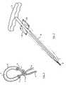
Comme le montre la Figure 1, le dispositif d'ancrage dela présente invention comprend un fil de suture (1) formantdans sa partie médiane une boucle fermée (2) par un noeudcoulant (3) susceptible d'être serré par simple traction surl'un des deux brins (4, 5) du fil (1).As shown in Figure 1, the anchoring device ofthe present invention comprises a suture (1) formingin its middle part a closed loop (2) by a knotflowing (3) can be tightened by simply pulling onone of the two strands (4, 5) of the wire (1).
Dans la boucle (2), le fil (1) est enveloppé par unegaine (6), déformable et compressible, susceptible de glissersur le fil. La traction sur le brin (4) du fil provoque unediminution de la longueur de la boucle (2) jusqu'à ce que salongueur devienne égale à celle de la gaine (6). En continuantla traction sur le brin (4) du fil (1), on provoque d'une partune compression de la gaine dont la surface forme des ondulationsen raison de la compressibilité de la matière qui laconstitue, et d'autre part le serrage du noeud (3). Les bordsde la gaine, à chacune de ses extrémités (7) et (8), sontrenforcés pour éviter qu'ils ne soient entaillés par le fil desuture lorsque celui-ci est serré. Ce renforcement est obtenuici par une simple surépaisseur de matière.In the loop (2), the wire (1) is wrapped by asheath (6), deformable and compressible, capable of slidingOn the string. Pulling on the strand (4) of the yarn causes adecreasing the length of the loop (2) until itslength becomes equal to that of the sheath (6). Continuingpulling on the strand (4) of the wire (1), one causes on the one handa compression of the sheath whose surface forms ripplesbecause of the compressibility of the material thatconstitutes, and on the other hand the tightening of the knot (3). Edgesof the sheath, at each of its ends (7) and (8), arereinforced to prevent them from being cut by the wire ofsuture when it is tight. This reinforcement is obtainedhere by a mere extra thickness of material.
La mise en place du dispositif s'effectue au moyen d'unmatériel ancillaire tel que décrit ci-après. La méthode demise en place consiste à introduire la boucle (2) portant lagaine (6) dans le trou foré dans l'os, puis à serrer en exerçantune traction sur le brin (4) du fil (1). Il est préférabled'introduire la totalité de la boucle dans le trou ainsique le noeud coulant (3).The device is put in place by means of aancillary equipment as described below. The method ofimplementation consists in introducing the loop (2) carrying thesheath (6) in the hole drilled in the bone, then to tighten by exertinga pull on the strand (4) of the wire (1). It is preferableto introduce the entire loop into the hole as wellas the noose (3).
Lorsque l'on serre le noeud coulant (3) en tirant sur lebrin (4) du fil, on provoque le rétrécissement de la boucle etla compression de la gaine flexible (6) à l'intérieur du trou.Puis en accentuant le serrage par traction sur le brin (4) dufil (1) on déforme la gaine (6) jusqu'à ce qu'elle prenne laforme d'une boule. Cette boule ne pourra ressortir par le troupar lequel on l'a introduite dans l'os car son diamètre estdevenu nettement supérieur à celui du trou foré. De plus cetteboule prend appui sur la face interne de l'os cortical ou dansl'os spongieux s'il est suffisamment dur.When tightening the noose (3) by pulling on thestrand (4) of the wire, it causes the narrowing of the loop andcompressing the flexible sheath (6) inside the hole.Then accentuating the tightening by pulling on the strand (4) of thewire (1) is deformed the sheath (6) until it takes theshape of a ball. This ball can not come out through the holeby which it was introduced into the bone because its diameter issignificantly higher than the hole drilled. In addition thisball leans on the inner side of the cortical bone or inspongy bone if it is hard enough.
Il suffit donc de choisir un fil de suture portant unegaine ayant une longueur et un diamètre permettant, parserrage du noeud coulant (3), la formation d'une boule quiprendra appui sur la face interne dure d'un os et dont lediamètre sera suffisamment important pour résister aux effortsqui lui sont imposés.It is therefore sufficient to choose a suture carrying asheath having a length and a diameter allowing, bytightening of the noose (3), the formation of a ball whichwill be supported on the hard inner side of a bone and whosediameter will be large enough to withstand the effortsimposed on him.
La pose du dispositif d'ancrage décrit ci-dessus s'effectueefficacement au moyen d'un matériel ancillaire conforme àl'invention, représenté sur la Figure 2.The installation of the anchoring device described above is carried outeffectively by means of ancillary equipment in accordance withthe invention, shown in Figure 2.
Sur cette Figure est représenté un matériel ancillairesimple facilitant la mise en place du dispositif d'ancragedans un trou préalablement foré dans un os.In this figure is represented an ancillary materialsimple facilitating the installation of the anchoring devicein a hole previously drilled in a bone.
Cet ancillaire comprend une pointe (9) destinée à supporterla boucle du fil de suture (1) pour assurer sa mise en place dans le trou foré dans l'os (non représenté). Cettepointe (9) est fixée sur un manche (10) solidaire d'unepoignée (11). Sur le manche (10) à proximité de la poignée(11) sont disposées deux plaquettes (12a) et (12b) sur lesquelleson place les deux extrémités du fil de suture (1) afinde faciliter leur manipulation par l'utilisateur.This ancillary includes a tip (9) for supportingthe loop of the suture (1) to ensure itsplace in the hole drilled in the bone (not shown). Thistip (9) is fixed on a handle (10) integral with ahandle (11). On the handle (10) near the handle(11) are arranged two plates (12a) and (12b) on whichboth ends of the suture (1) are placedto facilitate their manipulation by the user.
Après forage du trou dans l'os au moyen d'un appareilusuel, on introduit la pointe (9) portant le fil (1) formé enboucle portant sa gaine (6), dans le trou, puis on défait lesbrins (4) et (5) du fil (1) fixés sur les plaquettes (12a) et(12b). On retire l'ancillaire du trou en agissant sur lapoignée (11), puis on tire sur le brin (4) du fil (1) demanière à faire glisser le noeud coulant (3) et à déformer lagaine (6) pour qu'elle forme une boule.After drilling the hole in the bone using a devicestandard, the tip (9) carrying the wire (1) formed inbuckle carrying its sheath (6), in the hole, then we undo thestrands (4) and (5) of the wire (1) fixed on the wafers (12a) and(12b). We remove the ancillary hole by acting on thehandle (11), then pulling on the strand (4) of the wire (1) ofslip the slip knot (3) and deform thesheath (6) to form a ball.
L'ancillaire représenté sur la Figure 3 comporte unepointe (9), un manche (10), une poignée (11) et des plaquettes(12a) et (12b) identiques à ceux de la Figure 2, mais lapoignée et les plaquettes peuvent se déplacer axialement parrapport au manche.The ancillary shown in Figure 3 has atip (9), a handle (10), a handle (11) and pads(12a) and (12b) identical to those in Figure 2, but thehandle and the pads can move axially throughreport to the handle.
Une goupille (13) amovible permet de bloquer les deuxplaquettes porte-fil (12a) et (12b) tandis que la poignée estmaintenue en place sur la manche par simple encliquetage. Lemanche (10) est fendu par une rainure (14) qui permet ledéplacement des plaquettes lorsque la goupille (13) est enlevée.Cette rainure (14) est plus longue du côté de laplaquette (12b) que du côté de la plaquette (12a) de manière àlimiter le mouvement des plaquettes de manière différenciée,comme indiqué ci-après, le mouvement de translation de laplaquette (12b) pouvant s'effectuer sur une distance pluslongue que celui de la plaquette (12a). Ainsi, le brin du fil formant le noeud est fixé à la plaquette dont le mouvement estle plus important.A pin (13) removable can block bothwire plates (12a) and (12b) while the handle isheld in place on the sleeve by simply snapping. Thehandle (10) is split by a groove (14) which allows themoving the pads when the pin (13) is removed.This groove (14) is longer on the side of theplate (12b) than on the side of the wafer (12a) so as tolimit the movement of platelets in a different way,as shown below, the translational motion of theplate (12b) which can be carried out over a longer distancelonger than that of the wafer (12a). So, the strand of the wireforming the knot is attached to the wafer whose movement isMost important.
Comme le montre la Figure 4a, la rainure (14) est élargiedans la partie (15) recevant la poignée. Cette partie élargie(15) de la rainure comporte une butée (16), et elle est limitéepar les deux épaulements (17) et (18) formés sur chaquemoitié du manche. Cette butée et ces épaulements sont destinésà coopérer avec deux ergots (19) et (20) prévus sur l'axe (21)de la poignée (11).As shown in Figure 4a, the groove (14) is enlargedin the part (15) receiving the handle. This enlarged part(15) of the groove has a stop (16) and is limitedby the two shoulders (17) and (18) formed on eachhalf of the neck. This stop and these shoulders are intendedto cooperate with two lugs (19) and (20) provided on the axis (21)of the handle (11).
Lorsque la poignée est en place, son axe (21) est introduitdans le manche (10) jusqu'à ce que l'ergot (19) vienne enappui contre l'épaulement (18), l'ergot (20) étant alors enappui contre la partie inclinée de la butée (16).When the handle is in place, its axis (21) is introducedin the handle (10) until the pin (19) comes intobearing against the shoulder (18), the lug (20) being then inbearing against the inclined portion of the stop (16).
La tête de l'ergot (19) est de forme triangulaire, lapointe étant dirigée vers le fond de la rainure (14) tandisque sa base est dirigée vers la poignée (11). Par contre,l'ergot (20) a une tête à forme hexagonale. De la sorte, lorsquel'on tire avec une force suffisante sur la poignée (11)préalablement mise en place sur le manche (10), l'ergot (20),en raison de sa forme, peut passer sur la butée (17) en écartantles deux branches du manche (10) de part et d'autre de larainure (14), le déplacement étant limité par l'ergot (19)dont la base vient contre la butée (16). Dans cette position,l'ergot (20) a dépassé l'épaulement (17).The head of the lug (19) is of triangular shape, thetip being directed towards the bottom of the groove (14) whilethat its base is directed towards the handle (11). On the other hand,the lug (20) has a hexagonal shaped head. In this way, whenthe handle is pulled with sufficient force (11)previously put in place on the handle (10), the lug (20),because of its shape, can pass on the stop (17) by spreadingthe two branches of the handle (10) on either side of thegroove (14), the displacement being limited by the lug (19)whose base comes against the stop (16). In this position,the lug (20) has protruded from the shoulder (17).
Ce mouvement de la poignée (11) par rapport au manche(10) ne peut s'effectuer qu'en exerçant une force de tractionprédéterminée sur la poignée, de manière à surmonter la résistancede la butée (17) contre l'un des pans hexagonaux del'ergot (20) et à forcer l'écartement des deux branches dumanche de part et d'autre de la rainure (14). Ainsi, unefaible traction sur la poignée (11) entraíne le manche (10) avec la poignée, tandis qu'une traction plus forte désolidarisela poignée du manche.This movement of the handle (11) relative to the handle(10) can only be carried out by exerting a traction forcepredetermined on the handle, so as to overcome the resistanceof the abutment (17) against one of the hexagonal faces ofthe pin (20) and to force the spacing of the two branches of thehandle on both sides of the groove (14). So, alow traction on the handle (11) drives the handle (10)with the handle, while a stronger pull disengagesthe handle of the handle.
La mise en place du dispositif d'ancrage au moyen dumatériel ancillaire de la Figure 3 s'effectue de manière semi-automatiquecomme décrit ci-après.The installation of the anchoring device by means ofancillary equipment in Figure 3 is performed semi-automaticallyas described below.
Le dispositif d'ancrage est tout d'abord introduit dansun trou foré au préalable dans l'os. A cet effet, la bouclefermée portant la gaine flexible est placée sur la pointe (9)et les extrémités du fil de suture sont fixées sur lesplaquettes porte-fil (12a) et (12b) comme dans l'exempleprécédent, les deux brins du fil étant tendus entre la pointeet chaque plaquette.The anchoring device is first introduced intoa hole drilled beforehand into the bone. For this purpose, the loopclosed bearing flexible sheath is placed on the tip (9)and the ends of the suture are attached to thewire plates (12a) and (12b) as in the examplepreceding, the two strands of the wire being stretched between the tipand each wafer.
La pointe portant le fil est introduite dans le trou forédans l'os et la goupille (13) est enlevée afin de libérer lesdeux plaquettes qui peuvent coulisser sur le manche (10).L'utilisateur exerce une légère traction sur la poignée, quiprovoque le retrait de la pointe du trou, la poignée et lemanche restant solidaires. Dans le même temps la boucle, sagaine et le noeud, restent dans le trou, en raison des forcesde frottement. Puis étant donné que les plaquettes peuventcoulisser sur le manche (10), la plaquette (12a) va venir enappui contre le fond de la rainure (14) et va tendre le brin(4). Ceci va provoquer le serrage du noeud (3) et la déformationde la gaine (6) jusqu'à ce qu'elle forme une boule. Sil'utilisateur poursuit sa traction sur la poignée, au-delàd'une valeur prédéterminée, la force de traction est supérieureà la résistance opposée par la butée (17) sur l'ergothexagonal (20) et la poignée coulisse alors par rapport aumanche jusqu'à ce que l'ergot triangulaire (19) vienne contrela butée (16). Ceci permet de régler la force à exercer sur lebrin (4) pour assurer l'ancrage de la gaine (6) qui s'est transformée en boule, et le fait que l'ergot (15) vienne enbutée contre (16) évite au manche (10) de tomber.The point carrying the wire is introduced into the drilled holein the bone and the pin (13) is removed in order to release thetwo plates that can slide on the handle (10).The user exerts a slight pull on the handle, whichcauses the removal of the tip of the hole, the handle and thesleeve remaining solidary. At the same time the loop, itssheath and the knot, stay in the hole, because of the forcesfriction. Then since platelets canslide on the handle (10), the plate (12a) will come intosupport against the bottom of the groove (14) and will stretch the strand(4). This will cause the tightening of the knot (3) and the deformationfrom the sheath (6) until it forms a ball. Yesthe user continues to pull on the handle, beyondof a predetermined value, the pulling force is greaterat the resistance opposed by the abutment (17) on the spurhexagonal (20) and the handle then slides relative to thehandle until the triangular lug (19) comes againstthe stop (16). This makes it possible to regulate the force to exert on thestrand (4) for anchoring the sheath (6) which hastransformed into a ball, and the fact that the pin (15) comes intostop against (16) prevents the handle (10) from falling.
Le matériel ancillaire dont les deux éléments constitutifssont représentés sur les Figures 5 et 6 est destiné à unemise en place automatique du dispositif d'ancrage de l'invention,l'utilisateur pouvant dans ce cas manipuler l'ancillaired'une seule main.Ancillary equipment including the two constituent elementsare shown in Figures 5 and 6 is intended for aautomatic installation of the anchoring device of the invention,the user can in this case manipulate the ancillarywith one hand.
L'élément de la Figure 5 est un support recevant celui dela Figure 6. Ce dernier est similaire au matériel ancillairede la Figure 3, la poignée (11) étant remplacée par un poussoir(22).The element of Figure 5 is a support receiving that ofFigure 6. The latter is similar to ancillary equipmentof Figure 3, the handle (11) being replaced by a pusher(22).
L'élément support de la Figure 5 comprend un supporthémicylindrique (23) destiné à recevoir le manche (10) del'élément de la Figure 6. Pour assurer un bon maintien dumanche, ce support est refermé dans sa partie distale (24).Ainsi la mise en place de l'autre élément se fait en introduisantl'extrémité du manche (10) portant la pointe (9) dans lapartie ouverte du support (23) et en la faisant glisser dansla partie fermée (24) jusqu'à ce que le poussoir (22) vienneentre les deux butées (25) et (26) solidaires du support.The support element of Figure 5 includes a supportsemi-cylindrical (23) for receiving the handle (10) ofthe element of Figure 6. To ensure proper maintenance of thehandle, this support is closed in its distal portion (24).So the establishment of the other element is done by introducingthe end of the handle (10) carrying the tip (9) in theopen part of the support (23) and dragging it intothe closed part (24) until the pusher (22) comesbetween the two abutments (25) and (26) integral with the support.
La partie (28) du support portant les butées (25) et (26)peut coulisser sur l'axe (27), le mouvement de coulissementétant effectué en agissant sur la poignée (29) solidaire dusupport (28) et sur la poignée (30) solidaire de l'axe (27)(les deux poignées sont maintenues écartées par un ressort nonreprésenté). L'extrémité de l'axe (27) est solidaire de lapartie (31) du support qui porte le tube ouvert (23). Lorsquela goupille (13) est en place, son axe (32) s'engage dans letrou (33) prévu dans le support (28) et l'axe (27) et ainsiles deux poignées sont bloquées l'une par rapport à l'autre.The portion (28) of the support carrying the stops (25) and (26)can slide on the axis (27), the sliding movementbeing effected by acting on the handle (29) secured to thesupport (28) and on the handle (30) secured to the shaft (27)(both handles are held apart by a non-springrepresent). The end of the shaft (27) is integral with thepart (31) of the support carrying the open tube (23). Whenthe pin (13) is in place, its axis (32) engages in thehole (33) provided in the support (28) and the axis (27) andthe two handles are locked relative to each other.
L'utilisateur saisit l'ancillaire, comprenant les deuxéléments des Figures 5 et 6 assemblés, par les deux poignées(29) et (30) d'une seule main, il engage la pointe (9) portantla boucle et la gaine dans le trou préalablement foré dansl'os, puis il enlève la goupille (13) libérant ainsi lespoignées (29) et (30). En agissant sur les poignées de manièreà les rapprocher, il provoque un mouvement de retrait dumanche (10) qui coulisse dans le support hémicylindrique (23)provoquant le coulissement de la plaquette (12a) par rapportau manche (10) jusqu'à venir en butée contre le fond de larainure (14), puis le brins (4) se tend et provoque le serragedu noeud (3) et la transformation de la gaine (6) en boule.L'utilisateur doit continuer à serrer les poignées jusqu'à ceque le poussoir (22) se casse au niveau de son rétrécissement.Ceci indique à l'utilisateur qu'il a exercé la force nécessaireà la mise en place du système d'ancrage.The user enters the ancillary, including bothelements of Figures 5 and 6 assembled by the two handles(29) and (30) with one hand, it engages the point (9) carryingthe loop and the sheath into the hole previously drilled inthe bone, then he removes the pin (13) thus releasing thehandles (29) and (30). By acting on the handles soto bring them closer, it causes a withdrawal movement of thesleeve (10) which slides in the semicylindrical support (23)causing the wafer (12a) to slide relative toat the handle (10) until abutting against the bottom of thegroove (14), then the strands (4) tension and cause tighteningof the knot (3) and the transformation of the sheath (6) into a ball.The user must continue to tighten the handles untilthat the pusher (22) breaks at the level of its narrowing.This indicates to the user that he has exerted the necessary forcethe installation of the anchoring system.
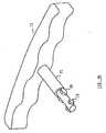
La Figure 7 montre explicitement la position du fil desuture (1) en boucle fermée et portant la gaine flexible (3)mis en place sur la pointe (9) à l'extrémité du manche (10) del'ancillaire de pose.Figure 7 shows explicitly the position of the wire ofsuture (1) in a closed loop and carrying the flexible sheath (3)placed on the tip (9) at the end of the handle (10) ofthe ancillary pose.
Claims (11)
- Surgical device for anchorage in bone that can beused in orthopedic, traumatological, gynecological andcarcinological surgery, in combination with a hole boredbeforehand in the bony support, comprising a thread (1) inthe form of a loop (2) closed by a running knot (3),characterizedin the middle part of the thread (1), which isintended to be introduced into the hole, carries a deformabletubular sleeve (6) which can slide along the thread (1)within the limits of the loop (2), and can be made into aloop by tension exerted on at least one strand (4) of thethread (1).
- Device according to Claim 1,characterized in thatthe length of the sleeve (6) is less than or equal to twicethe depth of the hole bored in the bony support.
- Device according to any of the preceding claims,characterized in that the diameter of the sleeve (6) is lessthan or equal to the diameter of the hole.
- Device according to any of the preceding claims,characterized in that the sleeve (6) is made of a singleelement or of several elements.
- Device according to Claim 4,characterized in thatthe sleeve (6) is made of a single linear cylindrical elementopen at both ends (7, 8).
- Device according to Claim 5,characterized in thatthe sleeve comprises at least one orifice passing through itswall for the passage of the two strands of thread or wire.
- Device according to Claim 4,characterized in thatthe sleeve (6) is made of a toric ring having at least oneorifice passing through its wall for the passage of the twostrands of thread or wire.
- Ancillary for inserting the anchoring Deviceaccording to Claim 1, comprising a shaft (10) having a handle(11) at one end for manipulation by the user, and at leastone thread-carrying support (12a, 12b) secured to the shaft(10) and carrying the ends of the thread or wire,characterized in that the shaft (10) comprises at the other end a spike (9) that can hold the loop (2) of thread (1) andbe introduced into the hole bored in the bone.
- Ancillary according to Claim 8,characterized inthat the handle (11) can slide longitudinally with respect tothe shaft (10) over a distance which is limited by at leastone stop (16), and the shaft or the handle comprises means(16, 19) for locking their relative position until apredetermined tensile force is applied to the handle (11) orto the shaft (10).
- Ancillary according to either one of claims 8 and9,characterized in that each thread-carrying support (12a,12b) consists of a small plate arranged on the shaft (10),the two small plates being situated one on either side of theaxis of the shaft, and capable of sliding along the shaftover distances which differ from one another.
- Ancillary according to claim 10,characterized inthat the end of the strand of thread carrying the runningknot is fixed to the small plate that can slide over thelongest distance, while the end of the other strand of threador wire, which does not carry the running knot, is attachedto the small plate which is stationary or slides over ashorter distance.
Applications Claiming Priority (2)
| Application Number | Priority Date | Filing Date | Title |
|---|---|---|---|
| FR9702422AFR2760185B1 (en) | 1997-02-28 | 1997-02-28 | SURGICAL BONE AND ANCILLARY ANCHORING DEVICE FOR ITS PLACEMENT |
| FR9702422 | 1997-02-28 |
Publications (2)
| Publication Number | Publication Date |
|---|---|
| EP0861633A1 EP0861633A1 (en) | 1998-09-02 |
| EP0861633B1true EP0861633B1 (en) | 2005-01-05 |
Family
ID=9504297
Family Applications (1)
| Application Number | Title | Priority Date | Filing Date |
|---|---|---|---|
| EP98400415AExpired - LifetimeEP0861633B1 (en) | 1997-02-28 | 1998-02-20 | Bone anchoring device and insertion instrument |
Country Status (5)
| Country | Link |
|---|---|
| US (1) | US5989252A (en) |
| EP (1) | EP0861633B1 (en) |
| AT (1) | ATE286366T1 (en) |
| DE (1) | DE69828457D1 (en) |
| FR (1) | FR2760185B1 (en) |
Cited By (3)
| Publication number | Priority date | Publication date | Assignee | Title |
|---|---|---|---|---|
| US9119893B2 (en) | 2010-11-04 | 2015-09-01 | Linvatec Corporation | Method and apparatus for securing an object to bone, including the provision and use of a novel suture assembly for securing an object to bone |
| US9307978B2 (en) | 2010-11-04 | 2016-04-12 | Linvatec Corporation | Method and apparatus for securing an object to bone, including the provision and use of a novel suture assembly for securing an object to bone |
| US9307977B2 (en) | 2010-11-04 | 2016-04-12 | Conmed Corporation | Method and apparatus for securing an object to bone, including the provision and use of a novel suture assembly for securing suture to bone |
Families Citing this family (138)
| Publication number | Priority date | Publication date | Assignee | Title |
|---|---|---|---|---|
| US5540718A (en)* | 1993-09-20 | 1996-07-30 | Bartlett; Edwin C. | Apparatus and method for anchoring sutures |
| FR2774580B1 (en)* | 1998-02-06 | 2000-09-08 | Laurent Fumex | BONE ANCHORING SURGICAL DEVICE |
| DE69931018T2 (en) | 1998-12-30 | 2006-11-23 | Ethicon, Inc. | Thread belay device |
| US7153312B1 (en) | 1999-12-02 | 2006-12-26 | Smith & Nephew Inc. | Closure device and method for tissue repair |
| US7887551B2 (en) | 1999-12-02 | 2011-02-15 | Smith & Nephew, Inc. | Soft tissue attachment and repair |
| US6485504B1 (en)* | 2000-06-22 | 2002-11-26 | James A. Magovern | Hard or soft tissue closure |
| US9314235B2 (en) | 2003-02-05 | 2016-04-19 | Smith & Nephew, Inc. | Tissue anchor and insertion tool |
| US7608092B1 (en) | 2004-02-20 | 2009-10-27 | Biomet Sports Medicince, LLC | Method and apparatus for performing meniscus repair |
| WO2005096955A1 (en)* | 2004-04-07 | 2005-10-20 | Tze Liang Woffles Wu | Surgical thread |
| US7857830B2 (en) | 2006-02-03 | 2010-12-28 | Biomet Sports Medicine, Llc | Soft tissue repair and conduit device |
| US9801708B2 (en) | 2004-11-05 | 2017-10-31 | Biomet Sports Medicine, Llc | Method and apparatus for coupling soft tissue to a bone |
| US7909851B2 (en) | 2006-02-03 | 2011-03-22 | Biomet Sports Medicine, Llc | Soft tissue repair device and associated methods |
| US7905904B2 (en)* | 2006-02-03 | 2011-03-15 | Biomet Sports Medicine, Llc | Soft tissue repair device and associated methods |
| US7658751B2 (en) | 2006-09-29 | 2010-02-09 | Biomet Sports Medicine, Llc | Method for implanting soft tissue |
| US20060189993A1 (en) | 2004-11-09 | 2006-08-24 | Arthrotek, Inc. | Soft tissue conduit device |
| US8840645B2 (en) | 2004-11-05 | 2014-09-23 | Biomet Sports Medicine, Llc | Method and apparatus for coupling soft tissue to a bone |
| US8137382B2 (en) | 2004-11-05 | 2012-03-20 | Biomet Sports Medicine, Llc | Method and apparatus for coupling anatomical features |
| US8298262B2 (en)* | 2006-02-03 | 2012-10-30 | Biomet Sports Medicine, Llc | Method for tissue fixation |
| US7749250B2 (en) | 2006-02-03 | 2010-07-06 | Biomet Sports Medicine, Llc | Soft tissue repair assembly and associated method |
| US7905903B2 (en) | 2006-02-03 | 2011-03-15 | Biomet Sports Medicine, Llc | Method for tissue fixation |
| US8361113B2 (en)* | 2006-02-03 | 2013-01-29 | Biomet Sports Medicine, Llc | Method and apparatus for coupling soft tissue to a bone |
| US9017381B2 (en) | 2007-04-10 | 2015-04-28 | Biomet Sports Medicine, Llc | Adjustable knotless loops |
| US8118836B2 (en) | 2004-11-05 | 2012-02-21 | Biomet Sports Medicine, Llc | Method and apparatus for coupling soft tissue to a bone |
| US8088130B2 (en) | 2006-02-03 | 2012-01-03 | Biomet Sports Medicine, Llc | Method and apparatus for coupling soft tissue to a bone |
| US8128658B2 (en) | 2004-11-05 | 2012-03-06 | Biomet Sports Medicine, Llc | Method and apparatus for coupling soft tissue to bone |
| US8303604B2 (en) | 2004-11-05 | 2012-11-06 | Biomet Sports Medicine, Llc | Soft tissue repair device and method |
| US8034090B2 (en) | 2004-11-09 | 2011-10-11 | Biomet Sports Medicine, Llc | Tissue fixation device |
| US8998949B2 (en) | 2004-11-09 | 2015-04-07 | Biomet Sports Medicine, Llc | Soft tissue conduit device |
| US7914539B2 (en) | 2004-11-09 | 2011-03-29 | Biomet Sports Medicine, Llc | Tissue fixation device |
| US7608098B1 (en) | 2004-11-09 | 2009-10-27 | Biomet Sports Medicine, Llc | Bone fixation device |
| US20070162135A1 (en)* | 2005-06-15 | 2007-07-12 | Jerome Segal | Mechanical apparatus and method for artificial disc replacement |
| US8021426B2 (en)* | 2005-06-15 | 2011-09-20 | Ouroboros Medical, Inc. | Mechanical apparatus and method for artificial disc replacement |
| US7442210B2 (en) | 2005-06-15 | 2008-10-28 | Jerome Segal | Mechanical apparatus and method for artificial disc replacement |
| US7601172B2 (en) | 2005-06-15 | 2009-10-13 | Ouroboros Medical, Inc. | Mechanical apparatus and method for artificial disc replacement |
| US7547319B2 (en) | 2005-06-15 | 2009-06-16 | Ouroboros Medical | Mechanical apparatus and method for artificial disc replacement |
| US20060293709A1 (en) | 2005-06-24 | 2006-12-28 | Bojarski Raymond A | Tissue repair device |
| US20070156174A1 (en)* | 2006-01-03 | 2007-07-05 | Arthrotek, Inc. | Method and apparatus for repairing a meniscus |
| US8574235B2 (en) | 2006-02-03 | 2013-11-05 | Biomet Sports Medicine, Llc | Method for trochanteric reattachment |
| US11311287B2 (en) | 2006-02-03 | 2022-04-26 | Biomet Sports Medicine, Llc | Method for tissue fixation |
| US10517587B2 (en) | 2006-02-03 | 2019-12-31 | Biomet Sports Medicine, Llc | Method and apparatus for forming a self-locking adjustable loop |
| US8652171B2 (en)* | 2006-02-03 | 2014-02-18 | Biomet Sports Medicine, Llc | Method and apparatus for soft tissue fixation |
| US8771352B2 (en) | 2011-05-17 | 2014-07-08 | Biomet Sports Medicine, Llc | Method and apparatus for tibial fixation of an ACL graft |
| US8562647B2 (en) | 2006-09-29 | 2013-10-22 | Biomet Sports Medicine, Llc | Method and apparatus for securing soft tissue to bone |
| US8652172B2 (en) | 2006-02-03 | 2014-02-18 | Biomet Sports Medicine, Llc | Flexible anchors for tissue fixation |
| US9271713B2 (en) | 2006-02-03 | 2016-03-01 | Biomet Sports Medicine, Llc | Method and apparatus for tensioning a suture |
| US8251998B2 (en) | 2006-08-16 | 2012-08-28 | Biomet Sports Medicine, Llc | Chondral defect repair |
| US8562645B2 (en) | 2006-09-29 | 2013-10-22 | Biomet Sports Medicine, Llc | Method and apparatus for forming a self-locking adjustable loop |
| US8506597B2 (en) | 2011-10-25 | 2013-08-13 | Biomet Sports Medicine, Llc | Method and apparatus for interosseous membrane reconstruction |
| US9408599B2 (en) | 2006-02-03 | 2016-08-09 | Biomet Sports Medicine, Llc | Method and apparatus for coupling soft tissue to a bone |
| US9468433B2 (en) | 2006-02-03 | 2016-10-18 | Biomet Sports Medicine, Llc | Method and apparatus for forming a self-locking adjustable loop |
| US11259792B2 (en) | 2006-02-03 | 2022-03-01 | Biomet Sports Medicine, Llc | Method and apparatus for coupling anatomical features |
| US9538998B2 (en) | 2006-02-03 | 2017-01-10 | Biomet Sports Medicine, Llc | Method and apparatus for fracture fixation |
| US9149267B2 (en) | 2006-02-03 | 2015-10-06 | Biomet Sports Medicine, Llc | Method and apparatus for coupling soft tissue to a bone |
| US9078644B2 (en) | 2006-09-29 | 2015-07-14 | Biomet Sports Medicine, Llc | Fracture fixation device |
| US8801783B2 (en) | 2006-09-29 | 2014-08-12 | Biomet Sports Medicine, Llc | Prosthetic ligament system for knee joint |
| US7959650B2 (en) | 2006-09-29 | 2011-06-14 | Biomet Sports Medicine, Llc | Adjustable knotless loops |
| US8968364B2 (en) | 2006-02-03 | 2015-03-03 | Biomet Sports Medicine, Llc | Method and apparatus for fixation of an ACL graft |
| US8597327B2 (en) | 2006-02-03 | 2013-12-03 | Biomet Manufacturing, Llc | Method and apparatus for sternal closure |
| US11259794B2 (en) | 2006-09-29 | 2022-03-01 | Biomet Sports Medicine, Llc | Method for implanting soft tissue |
| US8672969B2 (en) | 2006-09-29 | 2014-03-18 | Biomet Sports Medicine, Llc | Fracture fixation device |
| US9918826B2 (en) | 2006-09-29 | 2018-03-20 | Biomet Sports Medicine, Llc | Scaffold for spring ligament repair |
| US8500818B2 (en) | 2006-09-29 | 2013-08-06 | Biomet Manufacturing, Llc | Knee prosthesis assembly with ligament link |
| US12245759B2 (en) | 2008-08-22 | 2025-03-11 | Biomet Sports Medicine, Llc | Method and apparatus for coupling soft tissue to bone |
| US12419632B2 (en) | 2008-08-22 | 2025-09-23 | Biomet Sports Medicine, Llc | Method and apparatus for coupling anatomical features |
| US8361093B2 (en)* | 2009-01-23 | 2013-01-29 | Genesee Biomedical, Inc. | Band forming apparatus |
| US8343227B2 (en) | 2009-05-28 | 2013-01-01 | Biomet Manufacturing Corp. | Knee prosthesis assembly with ligament link |
| US12096928B2 (en) | 2009-05-29 | 2024-09-24 | Biomet Sports Medicine, Llc | Method and apparatus for coupling soft tissue to a bone |
| EP2263608B1 (en)* | 2009-06-19 | 2016-09-07 | Arthrex, Inc. | Bone-tendon-bone suture button construct |
| US8828053B2 (en) | 2009-07-24 | 2014-09-09 | Depuy Mitek, Llc | Methods and devices for repairing and anchoring damaged tissue |
| US8814903B2 (en) | 2009-07-24 | 2014-08-26 | Depuy Mitek, Llc | Methods and devices for repairing meniscal tissue |
| CA2713309C (en) | 2009-08-20 | 2013-07-02 | Howmedica Osteonics Corp. | Flexible acl instrumentation, kit and method |
| US9451938B2 (en) | 2010-04-27 | 2016-09-27 | DePuy Synthes Products, Inc. | Insertion instrument for anchor assembly |
| US9743919B2 (en) | 2010-04-27 | 2017-08-29 | DePuy Synthes Products, Inc. | Stitch lock for attaching two or more structures |
| US9597064B2 (en) | 2010-04-27 | 2017-03-21 | DePuy Synthes Products, Inc. | Methods for approximating a tissue defect using an anchor assembly |
| CA2797607A1 (en) | 2010-04-27 | 2011-11-03 | Synthes Usa, Llc | Anchor assembly including expandable anchor |
| US9345468B2 (en) | 2010-11-23 | 2016-05-24 | Medos International Sárl | Surgical filament snare assemblies |
| US8814905B2 (en) | 2010-11-23 | 2014-08-26 | Depuy Mitek, Llc | Surgical filament snare assemblies |
| WO2012088496A2 (en) | 2010-12-23 | 2012-06-28 | Depuy Mitek, Inc. | Adjustable anchor systems and methods |
| US8795334B2 (en) | 2011-01-28 | 2014-08-05 | Smith & Nephew, Inc. | Tissue repair |
| US12329373B2 (en) | 2011-05-02 | 2025-06-17 | Biomet Sports Medicine, Llc | Method and apparatus for soft tissue fixation |
| EP2704640B1 (en) | 2011-05-06 | 2021-07-07 | Linvatec Corporation | Soft anchor made from suture filament and suture tape |
| US9421008B2 (en) | 2011-09-23 | 2016-08-23 | Arthrex, Inc. | Soft suture-based anchors |
| US9357991B2 (en)* | 2011-11-03 | 2016-06-07 | Biomet Sports Medicine, Llc | Method and apparatus for stitching tendons |
| US9381013B2 (en) | 2011-11-10 | 2016-07-05 | Biomet Sports Medicine, Llc | Method for coupling soft tissue to a bone |
| US9314241B2 (en) | 2011-11-10 | 2016-04-19 | Biomet Sports Medicine, Llc | Apparatus for coupling soft tissue to a bone |
| US9370350B2 (en) | 2011-11-10 | 2016-06-21 | Biomet Sports Medicine, Llc | Apparatus for coupling soft tissue to a bone |
| US9445803B2 (en)* | 2011-11-23 | 2016-09-20 | Howmedica Osteonics Corp. | Filamentary suture anchor |
| EP2790599B1 (en) | 2011-12-14 | 2016-08-10 | DePuy Synthes Products, LLC | Device for compression across fractures |
| US9259217B2 (en) | 2012-01-03 | 2016-02-16 | Biomet Manufacturing, Llc | Suture Button |
| US8926662B2 (en) | 2012-02-01 | 2015-01-06 | Smith & Nephew, Inc. | Tissue graft anchoring |
| US10542966B2 (en) | 2012-03-02 | 2020-01-28 | S. Wendell Holmes, Jr. | Knotless suture anchor with internal suture locking mechanism |
| US9084597B2 (en) | 2012-03-09 | 2015-07-21 | Smith & Nephew, Inc. | Suture-based knotless repair |
| US8790370B2 (en) | 2012-03-30 | 2014-07-29 | Depuy Mitek, Llc | Surgical filament assemblies |
| US8894684B2 (en) | 2012-05-07 | 2014-11-25 | Medos International Sàrl | Systems, devices, and methods for securing tissue using a suture having one or more protrusions |
| US9060763B2 (en) | 2012-05-07 | 2015-06-23 | Medos International Sàrl | Systems, devices, and methods for securing tissue |
| US9345567B2 (en)* | 2012-05-07 | 2016-05-24 | Medos International Sàrl | Systems, devices, and methods for securing tissue using snare assemblies and soft anchors |
| US9421010B2 (en) | 2012-06-20 | 2016-08-23 | Arthrex, Inc. | Whipping suture anchor |
| US20140039552A1 (en) | 2012-08-03 | 2014-02-06 | Howmedica Osteonics Corp. | Soft tissue fixation devices and methods |
| US9463011B2 (en) | 2012-08-17 | 2016-10-11 | Arthrex, Inc. | Soft anchors with soft eyelets |
| US9232939B2 (en)* | 2012-09-11 | 2016-01-12 | Biomet Sports Medicine, Llc | Flexible planar member for tissue fixation |
| US9763655B2 (en) | 2012-09-20 | 2017-09-19 | Medos International Sarl | Systems, devices, and methods for securing tissue using hard anchors |
| US8986327B2 (en) | 2012-10-18 | 2015-03-24 | Smith & Nephew, Inc. | Flexible anchor delivery system |
| US9271716B2 (en) | 2012-12-27 | 2016-03-01 | Medos International Sàrl | Surgical constructs and methods for securing tissue |
| US9198650B2 (en)* | 2012-12-27 | 2015-12-01 | Medos International Sarl | Multi-piece anchor inserter |
| US9402620B2 (en) | 2013-03-04 | 2016-08-02 | Howmedica Osteonics Corp. | Knotless filamentary fixation devices, assemblies and systems and methods of assembly and use |
| US9757119B2 (en) | 2013-03-08 | 2017-09-12 | Biomet Sports Medicine, Llc | Visual aid for identifying suture limbs arthroscopically |
| US9974643B2 (en) | 2013-03-11 | 2018-05-22 | Medos International Sàrl | Implant having adjustable filament coils |
| US9788826B2 (en) | 2013-03-11 | 2017-10-17 | Howmedica Osteonics Corp. | Filamentary fixation device and assembly and method of assembly, manufacture and use |
| US10052094B2 (en) | 2013-03-11 | 2018-08-21 | Medos International Sàrl | Implant having adjustable filament coils |
| US9463013B2 (en) | 2013-03-13 | 2016-10-11 | Stryker Corporation | Adjustable continuous filament structure and method of manufacture and use |
| US9918827B2 (en) | 2013-03-14 | 2018-03-20 | Biomet Sports Medicine, Llc | Scaffold for spring ligament repair |
| US9737293B2 (en) | 2013-03-15 | 2017-08-22 | Medos International Sàrl | Surgical constructs with collapsing suture loop and methods for securing tissue |
| US10292694B2 (en) | 2013-04-22 | 2019-05-21 | Pivot Medical, Inc. | Method and apparatus for attaching tissue to bone |
| US9510820B2 (en)* | 2013-04-24 | 2016-12-06 | Medos International Sárl | Devices, systems, and methods for suture management |
| US9757113B2 (en) | 2013-07-31 | 2017-09-12 | Medos International Sàrl | Adjustable graft fixation device |
| AU2014342300A1 (en)* | 2013-10-29 | 2016-05-19 | Entourage Medical Technologies, Inc. | System for providing surgical access |
| US10405968B2 (en) | 2013-12-11 | 2019-09-10 | Medos International Sarl | Implant having filament limbs of an adjustable loop disposed in a shuttle suture |
| US10610211B2 (en) | 2013-12-12 | 2020-04-07 | Howmedica Osteonics Corp. | Filament engagement system and methods of use |
| US10136886B2 (en) | 2013-12-20 | 2018-11-27 | Biomet Sports Medicine, Llc | Knotless soft tissue devices and techniques |
| US10064670B2 (en) | 2014-05-12 | 2018-09-04 | DePuy Synthes Products, Inc. | Sacral fixation system |
| CA2949060A1 (en) | 2014-05-12 | 2015-11-19 | DePuy Synthes Products, Inc. | Sacral fixation system |
| US9615822B2 (en) | 2014-05-30 | 2017-04-11 | Biomet Sports Medicine, Llc | Insertion tools and method for soft anchor |
| US9700291B2 (en) | 2014-06-03 | 2017-07-11 | Biomet Sports Medicine, Llc | Capsule retractor |
| US10039543B2 (en) | 2014-08-22 | 2018-08-07 | Biomet Sports Medicine, Llc | Non-sliding soft anchor |
| US9622738B2 (en) | 2014-09-11 | 2017-04-18 | Arthrex, Inc. | Soft anchor assembly with non-sliding flexible strand and techniques for use |
| US9986992B2 (en) | 2014-10-28 | 2018-06-05 | Stryker Corporation | Suture anchor and associated methods of use |
| US10568616B2 (en) | 2014-12-17 | 2020-02-25 | Howmedica Osteonics Corp. | Instruments and methods of soft tissue fixation |
| US9955980B2 (en) | 2015-02-24 | 2018-05-01 | Biomet Sports Medicine, Llc | Anatomic soft tissue repair |
| US9974534B2 (en) | 2015-03-31 | 2018-05-22 | Biomet Sports Medicine, Llc | Suture anchor with soft anchor of electrospun fibers |
| US9888997B2 (en) | 2015-07-20 | 2018-02-13 | Arthrex, Inc. | Soft anchor assembly with barbed flexible strand and techniques for use |
| WO2017087848A1 (en)* | 2015-11-20 | 2017-05-26 | The Uab Research Foundation, Inc. | Knotless anchor devices and systems and uses thereof |
| JP6888556B2 (en)* | 2015-12-24 | 2021-06-16 | 日本ゼオン株式会社 | Endoscopic suture ligature |
| US10307154B2 (en)* | 2016-09-27 | 2019-06-04 | Arthrex, Inc. | Circular suture constructs and methods for use |
| US12059148B2 (en) | 2017-06-05 | 2024-08-13 | Conmed Corporation | Suture system and related methods for connecting and creating suspension between at least two bodies |
| US11911019B2 (en) | 2017-07-13 | 2024-02-27 | Conmed Corporation | All-suture anchor |
| USD902405S1 (en) | 2018-02-22 | 2020-11-17 | Stryker Corporation | Self-punching bone anchor inserter |
| US11272924B2 (en) | 2018-07-18 | 2022-03-15 | Arthrex, Inc. | Knotless closure sutures and methods of tissue fixation |
| US20210244402A1 (en)* | 2020-02-07 | 2021-08-12 | Dean Leffler | Orthopedic Soft Knotless Anchor With Sheath Maintained in Place by a Closed Link |
Family Cites Families (4)
| Publication number | Priority date | Publication date | Assignee | Title |
|---|---|---|---|---|
| US5217486A (en)* | 1992-02-18 | 1993-06-08 | Mitek Surgical Products, Inc. | Suture anchor and installation tool |
| CA2098896C (en)* | 1992-06-30 | 2005-03-29 | H. Jonathan Tovey | Specimen retrieval pouch and method for use |
| US5370662A (en)* | 1993-06-23 | 1994-12-06 | Kevin R. Stone | Suture anchor assembly |
| WO1995032669A1 (en)* | 1994-06-01 | 1995-12-07 | Perclose, Inc. | Apparatus and method for advancing surgical knots |
- 1997
- 1997-02-28FRFR9702422Apatent/FR2760185B1/ennot_activeExpired - Fee Related
- 1998
- 1998-02-20DEDE69828457Tpatent/DE69828457D1/ennot_activeExpired - Lifetime
- 1998-02-20EPEP98400415Apatent/EP0861633B1/ennot_activeExpired - Lifetime
- 1998-02-20ATAT98400415Tpatent/ATE286366T1/ennot_activeIP Right Cessation
- 1998-03-02USUS09/032,943patent/US5989252A/ennot_activeExpired - Fee Related
Cited By (3)
| Publication number | Priority date | Publication date | Assignee | Title |
|---|---|---|---|---|
| US9119893B2 (en) | 2010-11-04 | 2015-09-01 | Linvatec Corporation | Method and apparatus for securing an object to bone, including the provision and use of a novel suture assembly for securing an object to bone |
| US9307978B2 (en) | 2010-11-04 | 2016-04-12 | Linvatec Corporation | Method and apparatus for securing an object to bone, including the provision and use of a novel suture assembly for securing an object to bone |
| US9307977B2 (en) | 2010-11-04 | 2016-04-12 | Conmed Corporation | Method and apparatus for securing an object to bone, including the provision and use of a novel suture assembly for securing suture to bone |
Also Published As
| Publication number | Publication date |
|---|---|
| US5989252A (en) | 1999-11-23 |
| EP0861633A1 (en) | 1998-09-02 |
| DE69828457D1 (en) | 2005-02-10 |
| ATE286366T1 (en) | 2005-01-15 |
| FR2760185A1 (en) | 1998-09-04 |
| FR2760185B1 (en) | 1999-05-14 |
Similar Documents
| Publication | Publication Date | Title |
|---|---|---|
| EP0861633B1 (en) | Bone anchoring device and insertion instrument | |
| CA2320341C (en) | Surgical bone anchoring device | |
| US11523814B2 (en) | Swivel anchor for knotless fixation of tissue | |
| US9706986B2 (en) | Knotless suture and tissue securing method | |
| EP0886502B1 (en) | Tendon guide device | |
| EP0820722B1 (en) | Medical screw and installation tool for use in surgery | |
| US10238377B2 (en) | Anchors and methods for securing suture to bone | |
| US9295460B2 (en) | Anchors and method for securing suture to bone | |
| BE1014364A6 (en) | SUTURE BODY. | |
| EP0549779A1 (en) | Device for reinforcing a ligament transplant during reconstructive surgery. | |
| FR2847456A1 (en) | Anchoring screw insertable in a bone canal of a ligament graft e.g. for anterior cruciate ligament repair, includes conical intermediate threaded part and smooth rounded end having a diameter at least equal to diameter of bone canal | |
| WO1996029029A1 (en) | Surgical anchoring piece for ligaments | |
| FR2696338A1 (en) | Artificial ligament for use in knee joint and other body areas - comprises elongate thread with attachment portion formed at one end and separate transverse cylindrical fastening head attached to other end | |
| WO2013139985A2 (en) | System for attaching a ligament graft | |
| WO2022171801A1 (en) | Device for locking suture threads | |
| FR2623083A1 (en) | LIGAMENTARY OR TENDINOUS PROSTHESIS AND METHOD OF MAKING SAID PROSTHESIS | |
| FR2843291A1 (en) | Semi-automatic suture device using surgical thread consists of locking means for joining two thread ends at locking surface, support element with surface on tissue to be sutured and thread controlled tensioning means | |
| US20230338019A1 (en) | Suture tensioner and methods of tensioning | |
| EP1558179B1 (en) | Equipment for repairing biological tissue, such as a tendon or a ligament and, in particular, the calcanean tendon | |
| FR3086524A1 (en) | DEVICE FOR FIXING AT LEAST ONE SUTURE THREAD IN A BIOLOGICAL TISSUE | |
| FR2952296A1 (en) | Lamellar tissue e.g. osseous tendon, fixing device, has groove with preset depth below average thickness, to block tissue introduced into groove, and anti-extraction unit for providing anti-extraction to stud by wedging or fitting in hole |
Legal Events
| Date | Code | Title | Description |
|---|---|---|---|
| PUAI | Public reference made under article 153(3) epc to a published international application that has entered the european phase | Free format text:ORIGINAL CODE: 0009012 | |
| AK | Designated contracting states | Kind code of ref document:A1 Designated state(s):AT BE CH DE DK ES FI GB GR IE IT LI LU MC NL PT SE | |
| AX | Request for extension of the european patent | Free format text:AL;LT;LV;MK;RO;SI | |
| 17P | Request for examination filed | Effective date:19990211 | |
| AKX | Designation fees paid | Free format text:AT BE CH DE DK ES FI GB GR IE IT LI LU MC NL PT SE | |
| RBV | Designated contracting states (corrected) | Designated state(s):AT BE CH DE DK ES FI GB GR IE IT LI LU MC NL PT SE | |
| 17Q | First examination report despatched | Effective date:20020531 | |
| GRAP | Despatch of communication of intention to grant a patent | Free format text:ORIGINAL CODE: EPIDOSNIGR1 | |
| GRAS | Grant fee paid | Free format text:ORIGINAL CODE: EPIDOSNIGR3 | |
| GRAA | (expected) grant | Free format text:ORIGINAL CODE: 0009210 | |
| AK | Designated contracting states | Kind code of ref document:B1 Designated state(s):AT BE CH DE DK ES FI GB GR IE IT LI LU MC NL PT SE | |
| PG25 | Lapsed in a contracting state [announced via postgrant information from national office to epo] | Ref country code:NL Free format text:LAPSE BECAUSE OF FAILURE TO SUBMIT A TRANSLATION OF THE DESCRIPTION OR TO PAY THE FEE WITHIN THE PRESCRIBED TIME-LIMIT Effective date:20050105 Ref country code:IT Free format text:LAPSE BECAUSE OF FAILURE TO SUBMIT A TRANSLATION OF THE DESCRIPTION OR TO PAY THE FEE WITHIN THE PRESCRIBED TIME-LIMIT;WARNING: LAPSES OF ITALIAN PATENTS WITH EFFECTIVE DATE BEFORE 2007 MAY HAVE OCCURRED AT ANY TIME BEFORE 2007. THE CORRECT EFFECTIVE DATE MAY BE DIFFERENT FROM THE ONE RECORDED. Effective date:20050105 Ref country code:IE Free format text:LAPSE BECAUSE OF FAILURE TO SUBMIT A TRANSLATION OF THE DESCRIPTION OR TO PAY THE FEE WITHIN THE PRESCRIBED TIME-LIMIT Effective date:20050105 Ref country code:GB Free format text:LAPSE BECAUSE OF FAILURE TO SUBMIT A TRANSLATION OF THE DESCRIPTION OR TO PAY THE FEE WITHIN THE PRESCRIBED TIME-LIMIT Effective date:20050105 Ref country code:FI Free format text:LAPSE BECAUSE OF FAILURE TO SUBMIT A TRANSLATION OF THE DESCRIPTION OR TO PAY THE FEE WITHIN THE PRESCRIBED TIME-LIMIT Effective date:20050105 Ref country code:AT Free format text:LAPSE BECAUSE OF FAILURE TO SUBMIT A TRANSLATION OF THE DESCRIPTION OR TO PAY THE FEE WITHIN THE PRESCRIBED TIME-LIMIT Effective date:20050105 | |
| REG | Reference to a national code | Ref country code:GB Ref legal event code:FG4D Free format text:NOT ENGLISH | |
| REG | Reference to a national code | Ref country code:CH Ref legal event code:EP | |
| REG | Reference to a national code | Ref country code:IE Ref legal event code:FG4D Free format text:FRENCH | |
| REF | Corresponds to: | Ref document number:69828457 Country of ref document:DE Date of ref document:20050210 Kind code of ref document:P | |
| PG25 | Lapsed in a contracting state [announced via postgrant information from national office to epo] | Ref country code:LU Free format text:LAPSE BECAUSE OF NON-PAYMENT OF DUE FEES Effective date:20050220 | |
| PG25 | Lapsed in a contracting state [announced via postgrant information from national office to epo] | Ref country code:MC Free format text:LAPSE BECAUSE OF NON-PAYMENT OF DUE FEES Effective date:20050228 Ref country code:LI Free format text:LAPSE BECAUSE OF NON-PAYMENT OF DUE FEES Effective date:20050228 Ref country code:CH Free format text:LAPSE BECAUSE OF NON-PAYMENT OF DUE FEES Effective date:20050228 Ref country code:BE Free format text:LAPSE BECAUSE OF NON-PAYMENT OF DUE FEES Effective date:20050228 | |
| PG25 | Lapsed in a contracting state [announced via postgrant information from national office to epo] | Ref country code:SE Free format text:LAPSE BECAUSE OF FAILURE TO SUBMIT A TRANSLATION OF THE DESCRIPTION OR TO PAY THE FEE WITHIN THE PRESCRIBED TIME-LIMIT Effective date:20050405 Ref country code:GR Free format text:LAPSE BECAUSE OF FAILURE TO SUBMIT A TRANSLATION OF THE DESCRIPTION OR TO PAY THE FEE WITHIN THE PRESCRIBED TIME-LIMIT Effective date:20050405 Ref country code:DK Free format text:LAPSE BECAUSE OF FAILURE TO SUBMIT A TRANSLATION OF THE DESCRIPTION OR TO PAY THE FEE WITHIN THE PRESCRIBED TIME-LIMIT Effective date:20050405 | |
| PG25 | Lapsed in a contracting state [announced via postgrant information from national office to epo] | Ref country code:DE Free format text:LAPSE BECAUSE OF FAILURE TO SUBMIT A TRANSLATION OF THE DESCRIPTION OR TO PAY THE FEE WITHIN THE PRESCRIBED TIME-LIMIT Effective date:20050406 | |
| PG25 | Lapsed in a contracting state [announced via postgrant information from national office to epo] | Ref country code:ES Free format text:LAPSE BECAUSE OF FAILURE TO SUBMIT A TRANSLATION OF THE DESCRIPTION OR TO PAY THE FEE WITHIN THE PRESCRIBED TIME-LIMIT Effective date:20050416 | |
| NLV1 | Nl: lapsed or annulled due to failure to fulfill the requirements of art. 29p and 29m of the patents act | ||
| GBV | Gb: ep patent (uk) treated as always having been void in accordance with gb section 77(7)/1977 [no translation filed] | Effective date:20050105 | |
| REG | Reference to a national code | Ref country code:IE Ref legal event code:FD4D | |
| BERE | Be: lapsed | Owner name:FUMEX, LAURENT Effective date:20050228 | |
| REG | Reference to a national code | Ref country code:CH Ref legal event code:PL | |
| PLBE | No opposition filed within time limit | Free format text:ORIGINAL CODE: 0009261 | |
| STAA | Information on the status of an ep patent application or granted ep patent | Free format text:STATUS: NO OPPOSITION FILED WITHIN TIME LIMIT | |
| 26N | No opposition filed | Effective date:20051006 | |
| REG | Reference to a national code | Ref country code:GB Ref legal event code:FG4D Free format text:NOT ENGLISH | |
| BERE | Be: lapsed | Owner name:FUMEX, LAURENT Effective date:20050228 | |
| PG25 | Lapsed in a contracting state [announced via postgrant information from national office to epo] | Ref country code:PT Free format text:LAPSE BECAUSE OF NON-PAYMENT OF DUE FEES Effective date:20050605 |