EP0858775A1 - Fibrin sealant applicator - Google Patents
Fibrin sealant applicatorDownload PDFInfo
- Publication number
- EP0858775A1 EP0858775A1EP98101755AEP98101755AEP0858775A1EP 0858775 A1EP0858775 A1EP 0858775A1EP 98101755 AEP98101755 AEP 98101755AEP 98101755 AEP98101755 AEP 98101755AEP 0858775 A1EP0858775 A1EP 0858775A1
- Authority
- EP
- European Patent Office
- Prior art keywords
- applicator
- component
- conduits
- dispensing
- pair
- Prior art date
- Legal status (The legal status is an assumption and is not a legal conclusion. Google has not performed a legal analysis and makes no representation as to the accuracy of the status listed.)
- Granted
Links
- 108010080379Fibrin Tissue AdhesiveProteins0.000titleclaimsabstractdescription21
- 239000012190activatorSubstances0.000claimsabstractdescription51
- 108010049003FibrinogenProteins0.000claimsabstractdescription14
- 102000008946FibrinogenHuman genes0.000claimsabstractdescription14
- 229940012952fibrinogenDrugs0.000claimsabstractdescription14
- 108090000190ThrombinProteins0.000claimsabstractdescription13
- 229960004072thrombinDrugs0.000claimsabstractdescription13
- 230000007246mechanismEffects0.000claimsabstractdescription12
- 238000004891communicationMethods0.000claimsabstractdescription11
- 239000003364biologic glueSubstances0.000claimsabstractdescription7
- 239000000853adhesiveSubstances0.000claimsdescription11
- 230000001070adhesive effectEffects0.000claimsdescription11
- 238000005192partitionMethods0.000claimsdescription8
- 239000007788liquidSubstances0.000claimsdescription5
- 239000012530fluidSubstances0.000claimsdescription3
- 230000006835compressionEffects0.000claims1
- 238000007906compressionMethods0.000claims1
- 230000000694effectsEffects0.000claims1
- 239000000243solutionSubstances0.000description23
- 239000012460protein solutionSubstances0.000description21
- 235000004252protein componentNutrition0.000description5
- 235000018102proteinsNutrition0.000description5
- 102000004169proteins and genesHuman genes0.000description5
- 108090000623proteins and genesProteins0.000description5
- 206010052428WoundDiseases0.000description4
- 208000027418Wounds and injuryDiseases0.000description4
- 230000004913activationEffects0.000description4
- 230000000712assemblyEffects0.000description4
- 238000000429assemblyMethods0.000description4
- 239000000463materialSubstances0.000description4
- 238000000034methodMethods0.000description4
- 230000000740bleeding effectEffects0.000description3
- 238000011109contaminationMethods0.000description3
- 230000009977dual effectEffects0.000description3
- XLYOFNOQVPJJNP-UHFFFAOYSA-NwaterSubstancesOXLYOFNOQVPJJNP-UHFFFAOYSA-N0.000description3
- 208000015181infectious diseaseDiseases0.000description2
- 239000002184metalSubstances0.000description2
- 230000004048modificationEffects0.000description2
- 238000012986modificationMethods0.000description2
- 238000007789sealingMethods0.000description2
- 239000008223sterile waterSubstances0.000description2
- 239000003106tissue adhesiveSubstances0.000description2
- 102000004506Blood ProteinsHuman genes0.000description1
- 108010017384Blood ProteinsProteins0.000description1
- XUIMIQQOPSSXEZ-UHFFFAOYSA-NSiliconChemical compound[Si]XUIMIQQOPSSXEZ-UHFFFAOYSA-N0.000description1
- 241000700605VirusesSpecies0.000description1
- 230000009471actionEffects0.000description1
- 239000002671adjuvantSubstances0.000description1
- 235000021120animal proteinNutrition0.000description1
- 230000002421anti-septic effectEffects0.000description1
- 229940030225antihemorrhagicsDrugs0.000description1
- 229940064004antiseptic throat preparationsDrugs0.000description1
- 230000008901benefitEffects0.000description1
- 239000013060biological fluidSubstances0.000description1
- 238000004140cleaningMethods0.000description1
- 229940079593drugDrugs0.000description1
- 239000003814drugSubstances0.000description1
- 230000008030eliminationEffects0.000description1
- 238000003379elimination reactionMethods0.000description1
- 230000006870functionEffects0.000description1
- 239000002874hemostatic agentSubstances0.000description1
- 239000012535impuritySubstances0.000description1
- 238000000338in vitroMethods0.000description1
- 239000004615ingredientSubstances0.000description1
- 230000003993interactionEffects0.000description1
- 238000004519manufacturing processMethods0.000description1
- 229910001092metal group alloyInorganic materials0.000description1
- 239000000203mixtureSubstances0.000description1
- 210000000056organAnatomy0.000description1
- 230000000149penetrating effectEffects0.000description1
- 229920003023plasticPolymers0.000description1
- 229920000642polymerPolymers0.000description1
- 238000006116polymerization reactionMethods0.000description1
- 239000000843powderSubstances0.000description1
- 238000003825pressingMethods0.000description1
- 230000008569processEffects0.000description1
- 239000000565sealantSubstances0.000description1
- 229910052710siliconInorganic materials0.000description1
- 239000010703siliconSubstances0.000description1
- 238000001356surgical procedureMethods0.000description1
- 239000012780transparent materialSubstances0.000description1
Images


Classifications
- A—HUMAN NECESSITIES
- A61—MEDICAL OR VETERINARY SCIENCE; HYGIENE
- A61B—DIAGNOSIS; SURGERY; IDENTIFICATION
- A61B17/00—Surgical instruments, devices or methods
- A61B17/00491—Surgical glue applicators
- A—HUMAN NECESSITIES
- A61—MEDICAL OR VETERINARY SCIENCE; HYGIENE
- A61B—DIAGNOSIS; SURGERY; IDENTIFICATION
- A61B17/00—Surgical instruments, devices or methods
- A61B17/00491—Surgical glue applicators
- A61B2017/00495—Surgical glue applicators for two-component glue
Definitions
- the disclosurerelates generally to an applicator for applying a tissue sealant based on human or animal proteins and more particularly to an apparatus for applying an adhesive formed by combining solutions of the proteins to tissues or organs for sealing wounds, stopping bleeding and the like.
- a fibrin sealantis a biological adhesive formed by mixing two protein components, namely, fibrinogen and thrombin.
- Each protein componentis derived from human plasma and is subjected to virus elimination procedures.
- the componentsare typically individually dehydrated and stored in separate vials as sterile freeze-dried powders.
- Redl et al.disclose a mechanism in which two standardized one-way syringes are held in a support having a common actuating means. The dispensing end of each syringe is inserted into a collection manifold where the two components are mixed. The components are then dispensed through a common needle capable of covering a limited area of the application site.
- a dual syringe apparatus for the application of fibrinogen and thrombin solutions to an application sitegenerally contains several parts, such as a syringe plunger, a "Y" manifold connector, a dispensing needle, a syringe holder, syringe needles, and conduits for transporting the solutions to the dispensing needle. Therefore, known fibrin sealant applicators, such as disclosed in U.S. Patent to Redl et al. discussed above, and in U.S. Patent Nos. 4,874,368 to Miller et al. and 4,979,942 to Wolf et al. are difficult to reuse.
- the replenishment of the protein componentstypically require removing a clip which couples the syringe plunger, removing the syringe plunger, detaching the syringes from the "Y" connector, removing the syringes from the holder, inserting new syringes, affixing the syringes to the "Y" connector, adding fibrinogen to one syringe and thrombin to another syringe, adding sterile water to each syringe, replacing the syringe plunger, replacing the plunger clip, and mixing the solutions.
- a lengthy replenishing processis impractical and cumbersome.
- a fibrin sealant applicatorwherein the adhesive covers a broad area of a wound, either to stop bleeding, to fix tissue or to prevent infection.
- a fibrin sealant applicatorwherein a manual force is applied via a activator assembly having a mechanism for preventing air from entering reservoirs containing the solutions.
- the adhesive componentsare not susceptible to contamination and the adhesive components are not intermixed within the applicator.
- a fibrin sealant applicatorwherein the component solutions are easily replenished.
- a fibrin sealant applicatorwhich is self-cleaning and reusable with different component solutions.
- a fibrin sealant applicatorwhich is inexpensive to manufacture for allowing the applicator to be disposed of after use.
- a fibrin sealant applicatorwhich avoids wasting adhesive solution and allows the application site to be clearly seen by the user when applying the component solutions perpendicular to the application site.
- An applicatorfor dispensing a first and a second component of a biological adhesive.
- the applicatorincludes a housing having a housing head for enclosing therein a first reservoir containing the first component, and a second reservoir containing the second component.
- the housingfurther includes an elongated body portion defining a longitudinal axis for enclosing therein a conduit assembly having a first and a second conduit in communication with the first and second reservoir, respectively.
- An activator assemblyis provided which includes an activator and a rachet mechanism for compressing the reservoirs within the housing to dispense the biological components into the conduits.
- An applicator tip having two separate channels in communication with the conduitsmay be provided on a distal end of the elongated body portion for dispensing the components at the application site.
- the first and second componentsare preferably fibrinogen and thrombin which intermix to form a fibrin sealant.
- the applicator designated generally by numeral 10includes a housing 12 having a housing head 14 and an elongated body portion 16 defining a longitudinal axis.
- Housing head 14contains a conically-shaped distal end 18 having a bore 20 in the center thereof dimensioned to receive body portion 16. While the housing head 14 is shown as being rectangular, it is understood that other shapes that contribute to the ease of gripping and controlling the applicator 10 may be used.
- the housing head 14includes an opening 20 for receiving an activator assembly 22 having an activator 24 for effectuating the dispensing of biological components as further described below.
- An applicator tip 26is provided at a distal end 28 of the body portion 16 having two boresights 30 for dispensing biological components contained within housing head 14.
- the biological componentsare a fibrinogen solution and a thrombin solution which intermix to form a fibrin sealant. It is to be understood, however, that other biological fluids may be substituted, depending upon the choice of mixture that is to be dispensed.
- housing 12is formed from molded housing half sections 12a and 12b which are formed with internal partitions configured to properly align the internal components of the applicator 10 with respect to each other and to prevent movement of the components.
- the internal components of the applicator 10include a reservoir assembly 32 and a conduit assembly 34. The two assemblies are interrelated with each other and with the activator assembly 22 discussed above.
- Reservoir assembly 32includes a first 36 and second reservoir 38, and two plugs 40.
- First reservoir 36 and second reservoir 38are preferably constructed from a flexible material and contain the first and second biological components, respectively.
- a window 37 on housing half-section 12awill permit a user to view the contents within the first 36 and second reservoir 38.
- First 36 and second reservoir 38include a first cylindrical extension 42 having a central throughbore 44 at a distal end 46, a second cylindrical extension 48 having a central throughbore 50 at a proximal end 52.
- Central throughbore 50is used for placing the biological components in the reservoirs 36 and 38.
- Plug 40is used to vacuum seal central throughbore 50 to prevent contamination of the biological components.
- the plug 40includes a silicon surface 56 capable of being penetrated by a syringe needle for adding a liquid, preferably sterile water, within reservoirs 36 and 38 to intermix with the biological components to form protein solutions.
- a liquidpreferably sterile water
- the protein solutionsare dispensed on the application site, as further discussed below.
- the conduit assembly 34includes two conduits 58 each having a nozzle 60 for matingly engaging the cylindrical extension 42 on first 36 and second reservoir 38 for connecting conduit assembly 34 to reservoir assembly 32.
- the conduit assembly 34is mounted within housing 12 as illustrated by the dotted lines in FIG. 2
- Two phantom channels 61 within applicator tip 26, each leading to one of the two boresights 30,are preferably press fitted to the distal end of the conduits 58 for providing fluid communication between the conduit assembly 34 and the applicator tip 26.
- FIG. 2Ais an enlarged view of a portion of the activator assembly 22.
- the activator assembly 22controls the pressure exerted on reservoirs 36 and 38, and includes the activator 24 and a rachet member 62.
- the activator 24includes an activation area 64, a shaft 66, and a disc 68.
- the shaft 66connects the activation area 64 with the disc 68.
- the rachet member 62extends downwardly from disc 68 and includes teeth 70 for engaging teeth 72 on an inner extension 74 of housing 12 to form structure for controlling the position of the activator 24.
- the control structureis a rachet mechanism 73.
- the rachet member 62is preferably formed integral with the disc 68.
- Activator 24may be formed with a transparent material or with a transparent window therein to permit viewing of the internal components of the applicator 10.
- FIG. 3An assembled cross-sectional, top view of the applicator 10 illustrating the flow of the protein solutions is shown by FIG. 3.
- the protein solutionsare kept separated to prevent intermixing and the creation of a fibrin sealant within the applicator 10.
- componentsare forced through conduit assembly 34 to applicator tip 26.
- FIG. 4illustrates a preferred embodiment of the reservoir assembly 32.
- the first and second reservoir 38are identical for encasing an equal volumetric amount of their respective protein solution as compared to the other reservoir. It is contemplated to provide a different color for each reservoir 36 and 38 to easily recognize the reservoir containing fibrinogen and the reservoir containing thrombin. It is further contemplated to provide a different shape for each reservoir for the same purpose. However, the volumetric amount stored within the first reservoir 36 should be equal to the volumetric amount stored within the second reservoir 38 to maintain a pre-determined fibrinogen to thrombin solution ratio, which is typically a 1:1 ratio.
- FIG. 4AA perspective view of the reservoir assembly 32 of FIG. 4 as placed within housing 12 is illustrated by FIG. 4A. It is contemplated that the first 36 and the second reservoir 38 are manufactured from a transparent plastic for being able to view the amount of solution and to determine if the solution has been sufficiently intermixed before being dispensed on the application site. It is further contemplated to provide calibration markings on the first 36 and second reservoir 38. It is additionally contemplated that reservoir assembly 32 is permanently affixed to the conduit assembly 34. In such an embodiment, the reservoir assembly 32 and the conduit assembly 34 can be disposed of after each use and new reservoir and conduit assemblies can be fitted to applicator 10.
- FIGS. 5 and 5Aillustrate an alternative embodiment of applicator 10 and reservoir assembly 32.
- Reservoir assembly 76 illustrated by FIG. 5includes a first 78 and second reservoir 80 having cylindrical extensions 82 fitted with plugs 84 for sealing the components.
- the applicator illustrated by FIG. 5A and designated generally by numeral 86is identical to applicator 10 without entry holes 54; with a different partition layout on housing half-section 12b and with a different connecting method for connecting reservoirs 78 and 80 with conduit assembly 88.
- conduit assembly 88includes nozzles 90 having a syringe needle (not shown) in a center thereof for penetrating surface 92 on plugs 84.
- the protein solutionare dispensed to conduit assembly 94 via the syringe needles.
- Two mounts 96are provided to conduit assembly 88 to create a force directed towards the proximal end of applicator 86 when reservoirs 78 and 80 are forced against the syringe needles to permit the syringe needles to penetrate surface 92 of each plug 84.
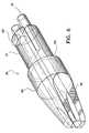
- the applicator tip 26is preferably made from a metallic alloy capable of being sterilized and includes a cylindrical proximal end 97 and an applicator head 98. Further, as mentioned above, applicator tip 26 includes two channels 61 for matingly engaging conduits 58. Each channel 61 extends through the applicator tip 26 to one of the two boresights 30 for dispensing the protein solutions to the application site.
- the cylindrical proximal endincludes a clasping button 100 for matingly engaging a hole 102 in body portion 16. When applicator tip 26 is connected to body portion 16, a circumferential surface 104 dividing the cylindrical proximal end 96 with the applicator head 106 is made flush with a distal end surface 108 of body portion 16.
- FIG. 7depicts the applicator 10 with the activator 24 in an inactivated state
- the activator 24is maintained in the inactivated state by the rachet mechanism 73 which has teeth 70 on rachet member 62 for lockingly engaging teeth 72 on the inner extension of 74 of housing 12.
- FIGS. 8 and 8Athere is illustrated the activator assembly 22 in an activated state.
- the rachet mechanism 73guides the activator 24 downwardly and the shaft 66 is forced further into the housing 12.
- the rachet mechanism 73 and the disc 68compress reservoir 36 to dispense the protein solution via nozzle 60 into conduit assembly 34.
- the activator 24When ceasing to exert pressure to the activation area 64, the activator 24 is prevented from returning to the inactivated state by the rachet mechanism 73. As a result air cannot be sucked into the reservoirs 36 and 38 causing difficulty in further compressing reservoirs 36 and 38. Further, the position of the activator 24 with respect to housing half-section 12a provides a reference as to the amount of solution remaining in the first 36 and second reservoir 38. For example, when the activator 24 is in a fully activated state, as shown by FIG. 9, there is a small amount of solution left in the first 36 and second reservoir 38.
- reservoir 150as reservoir 36, includes includes plug 40 to vacuum seal central throughbore 50 and the cylindrical extension 42 for connecting to the conduit assembly 34.
- reservoir 150is constructed from a collapsible or nonflexible material which prevents the reservoir 150 from resuming its original, uncompressed shape as depicted by FIG. 10 after being compressed. As shown by FIGS. 10A and 10B, after the reservoir 150 is compressed, it does not resume its original, uncompressed shape.
- FIGS. 11 and 11AAn alternative reservoir is illustrated by FIGS. 11 and 11A and is designated generally by numeral 110.
- Reservoir 110is identical to reservoir 36, but with the addition of a frangible partition 112.
- the partition 112separates the dehydrated protein 114 with the mixing liquid 116.
- the frangible partition 112is broken by applying pressure to the collapsible reservoir 110, as indicated by the arrows in FIG. 11A, to mix the ingredients therein to form the protein solution.
- the applicator 10could be fitted with any of a number of different reservoirs, including, without limitation, syringes, bags or tubing.
- the preferred embodiment for the reservoir assembly 32has but two reservoirs, it is to be understood that additional reservoirs containing other solutions can be incorporated within applicator 10.
- FIGS. 12-17illustrate alternative embodiments for the distal end of applicator 10.
- FIGS. 12 and 12Aillustrate body portion 16 being provided with bellows 118 for effectuating articulation of the applicator tip 26 for altering the dispensing angle with respect to longitudinal axis of the body portion 16.
- FIGS. 13 and 13Aillustrate body portion 16 having shape memory metal 120 for altering the dispensing angle as sleeve 122 is moved proximally.
- the memory metal 120resumes a straight configuration when sleeve 122 is pushed distally as shown by the arrow in FIG. 13A.
- FIGS. 14 and 14Athere is illustrated another embodiment for altering the dispensing angle.
- applicator tip 26has been removed and the distal end of body portion 16 is provided with an angular cut 124 having approximately a 45° angle with respect to the longitudinal axis.
- the conduits 58have curved distal ends to align with the 45° angular cut 124 for dispensing the protein solutions at a 45° angle from the longitudinal axis.
- FIGS. 15 and 16illustrate two additional alternative embodiments for the distal end of body portion 16. These embodiments include conduits which extend beyond the distal end of body portion 16.
- the embodiment of FIG. 15includes one straight conduit 126 and one conduit 128 having a circular configuration 130.
- the circular configuration 130is provided with holes 132 on a side 134 facing the center of the circular configuration 130.
- One of the protein solutionsexits the applicator 10 via holes 132 on conduit 128. This protein solution is intermixed with the protein solution which exits conduit 126.
- the embodiment of FIG. 15is best suited for providing the fibrin sealant on small incisions or cuts which can be localized by circular configuration 130.
- FIG. 16includes pads 136 fitted at the distal end of conduits 138.
- the pads 136are formed of a sponge-like material capable of absorbing the protein solutions.
- the pads 136are used to spread the protein solutions on the application site. This embodiment is best suited for external wounds or larger internal site configuration.
- body portion 16With reference to FIG. 17, there is illustrated an alternative embodiment for body portion 16.
- Two coaxial paths 140 and 142are formed within body portion 16.
- a portion of conduits 58are used to transport the protein solutions from the first 36 and second reservoir 38 to the proximal end of body portion 16 where they dispense the protein solutions within coaxial paths 140 and 142.
- the paths 140 and 142transport the solutions to the application site. It is contemplated that the paths 140 and 142 have an identical volumetric capacity for transpotting an equal amount of each solution to the application site.
- FIG. 18illustrates an applicator designated generally by numeral 200 having a housing 202 including a housing head 204 and an elongated body portion 206.
- An applicator tip 208is provided at a distal end 210 of body portion 206.
- An activator assembly 211is provided on housing head 204 having a first and a second set of lateral finger grips 212 and 214. The first set 212 is stationary and the second set 214 is configured for movement along two horizontal slots 216 provided on each side of housing head 204.
- a cylindrical drum 218is affixed to the second set of lateral finger grips 214.
- the drum 218rests against the proximal end of reservoirs 220 and 222.
- the second set of lateral finger grips 214are brought towards the first set 212.
- the forward lateral movement of the second set 214translates the drum 218 over reservoirs 220 and 222 to dispense the protein solutions via nozzles 224 to conduit assembly 226.
- the relative position of the second set of lateral finger grips 214 to the first set 212provides a reference regarding the amount of solution remaining in each reservoir 220 and 222.
- Applicator 300includes an activator assembly 302 having a pair of hinged-plates 304 connected via hinge 306 and a slide 308. Housing 310 is provided with a cut-out portion 312 for guiding the slide 308 forward to create a plying action on reservoirs 314 and 316, as shown by the arrows in FIG. 19B, to dispense the protein solutions via nozzles 318 to conduit assembly 320.
- the relative position of the slide 308 along the cut-out portion 312provides a reference regarding the amount of solution remaining in each reservoir 314 and 316.
- conduits which have different diametersmay be provided for allowing the biological components to be dispensed in different ratios.
- an activator assemblymay be provided which uses pressurized gas to dispense the components from the reservoirs.
Landscapes
- Health & Medical Sciences (AREA)
- Life Sciences & Earth Sciences (AREA)
- Surgery (AREA)
- Heart & Thoracic Surgery (AREA)
- Engineering & Computer Science (AREA)
- Biomedical Technology (AREA)
- Nuclear Medicine, Radiotherapy & Molecular Imaging (AREA)
- Medical Informatics (AREA)
- Molecular Biology (AREA)
- Animal Behavior & Ethology (AREA)
- General Health & Medical Sciences (AREA)
- Public Health (AREA)
- Veterinary Medicine (AREA)
- Surgical Instruments (AREA)
- Materials For Medical Uses (AREA)
Abstract
Description
Claims (26)
- An applicator for dispensing a multicomponent biological adhesive, theapplicator comprising:a housing configured to receive a plurality of collapsible reservoirs eachhaving a sealable opening therein;a conduit assembly having a pair of conduits, in respective fluidcommunication with separate of said reservoirs; andan activator assembly provided on said housing having an activatormoveable from a first position to a second position to compresseach of said plurality of reservoirs to dispense said componentsthrough said pair of conduits to a distal end thereof.
- The applicator of claim 1 further comprising an applicator tip having a pairof channels each being in fluid communication with said distal end of one of said pair ofconduits.
- The applicator of claim 1 wherein said activator assembly includes controlstructure for restricting said activator from returning to said first position after theactivator is moved from said first position.
- The applicator of claim 3 wherein said control structure includes a rachetmechanism.
- The applicator of claim 1 wherein said activator assembly includes a pairof hinged-plates mounted for engagement with said plurality of reservoirs and acompression assembly operably engageable with said hinged-plates to compress saidplurality of reservoirs as said activator is moved from said first to said second positionto dispense said components.
- The applicator of claim 1 wherein said activator assembly includes a drumand the activator is a pair of finger grips for effectuating movement of said drum as saidpair of finger grips are moved from said first to said second position.
- The applicator of claim 1 wherein each of said pair of conduits includeindependent distal exits, such that said first and second components intermix external tosaid applicator.
- The applicator of claim 1 wherein said conduit assembly furthercomprising a first nozzle disposed about a first of said pair of conduits and a secondnozzle disposed about a second of said pair of conduits.
- The applicator of claim 1 wherein said first component is a thrombinsolution and said second component is a fibrinogen solution, whereby said adhesive is afibrin sealant.
- The applicator of claim 1 wherein said adhesive comprises apredetermined ratio of said first component to said second component.
- The applicator of claim 1 wherein said housing includes a housing head forstoring said plurality of reservoirs therein and an elongated body portion extending fromsaid housing head.
- The applicator of claim 1, wherein each of said plurality of reservoirsincludes a frangible partition therein for separating said first component or said secondcomponent from a liquid.
- The applicator of claim 12 wherein said reservoirs include a first portioncontaining said first component or said second component and a second portion containingsaid liquid divided by said frangible partition.
- The applicator of claim 11 wherein a distal end of said elongated bodyportion includes structure for collectively altering the angle of dispensing of said firstcomponent and said second component at an angle with respect to a proximal end of theelongated body portion.
- The applicator of claim 14 wherein said means for altering the angle ofdispensing includes bellows for effectuating articulation of said distal end.
- The applicator of claim 14 wherein said moans for altering the angle ofdispensing includes a shape memory tube in alignment with said body portion and asleeve overlaying said tube, where said tube assumes a different angular configurationwith respect to a longitudinal axis of said body portion as said sleeve is movedproximally.
- The applicator of claim 14 wherein said means for altering the angle ofdispensing includes providing an angular cut to said distal end of said body portion andcurving a distal end of each of said pair of conduits to align with said angular cut.
- The applicator of claim 1 wherein a first of said pair of conduits includesa distal end having a circular configuration aligned with a plurality of holes on a sidefacing inward of said circular configuration, and a second of said pair of conduitsincludes a distal end substantially above the circular configuration.
- The applicator of claim 1 wherein a distal end of each of said pair ofconduits includes a pad for absorbing and spreading said first component and said secondcomponent.
- The applicator of claim 1 wherein said pair of conduits form coaxial pathswithin said body portion.
- An applicator for dispensing a first and a second component of a biologicaladhesive, the applicator comprising:a housing having a first dispensing conduit for dispensing the firstcomponent and a second dispensing conduit for dispensing the second componentindependent of the first component; andan activator assembly in communication with the dispensing conduits andboth a first reservoir containing the first component and a second reservoir containing thesecond component, for exerting pressure on the reservoirs for dispensing the componentsto the dispensing conduits.
- The applicator of claim 21 further comprising an applicator tip incommunication with the dispensing conduits.
- The applicator of claim 21 wherein said first component is a thrombinsolution and said second component is a fibrinogen solution, whereby said adhesive is afibrin sealant.
- The applicator of claim 21 wherein said dispensing conduits form coaxialpaths within said housing.
- A manually-operated applicator for dispensing a multicomponent biologicaladhesive, the applicator comprising:a conduit assembly having a pair of conduits;a collapsible reservoir assembly having a first reservoir containing the firstadhesive component and a second reservoir containing the second adhesive component,the first reservoir being in communication with a first of said pair of conduits and thesecond reservoir being in communication with a second of said pair of conduits; andan activator assembly having an activator for imparting pressure to said first andsecond reservoirs to effect dispensing of said first and second components to said pair ofconduits.
- The manually operated applicator of claim 25 wherein the conduit assemblyand the reservoir assembly are supported within a single housing.
Applications Claiming Priority (2)
| Application Number | Priority Date | Filing Date | Title |
|---|---|---|---|
| US792535 | 1997-01-31 | ||
| US08/792,535US6783514B2 (en) | 1997-01-31 | 1997-01-31 | Fibrin sealant applicator |
Publications (2)
| Publication Number | Publication Date |
|---|---|
| EP0858775A1true EP0858775A1 (en) | 1998-08-19 |
| EP0858775B1 EP0858775B1 (en) | 2004-01-07 |
Family
ID=25157247
Family Applications (1)
| Application Number | Title | Priority Date | Filing Date |
|---|---|---|---|
| EP98101755AExpired - LifetimeEP0858775B1 (en) | 1997-01-31 | 1998-02-02 | Fibrin sealant applicator |
Country Status (4)
| Country | Link |
|---|---|
| US (1) | US6783514B2 (en) |
| EP (1) | EP0858775B1 (en) |
| CA (1) | CA2228705C (en) |
| DE (1) | DE69820916T2 (en) |
Cited By (18)
| Publication number | Priority date | Publication date | Assignee | Title |
|---|---|---|---|---|
| WO2001074253A1 (en)* | 2000-03-31 | 2001-10-11 | 3M Innovative Properties Company | Dispenser for an adhesive tissue sealant having a flexible link distal section |
| WO2002055138A1 (en)* | 2001-01-12 | 2002-07-18 | Biovitrum Ab | A device and a method for dispensing at least two mutually reactive components |
| WO2003002005A1 (en)* | 2001-06-27 | 2003-01-09 | Biovitrum Ab | Dispenser |
| EP1076517A4 (en)* | 1998-05-06 | 2003-01-15 | Bristol Myers Squibb Co | Directional endoscopic delivery of material |
| US6596180B2 (en) | 1996-04-30 | 2003-07-22 | Medtronic, Inc. | System and method for the production of autologous platelet gel |
| WO2004110282A1 (en)* | 2003-06-13 | 2004-12-23 | Medlogic Global Limited | Dual-ended applicator for dispensing two fluids, in particular glue components |
| US6863660B2 (en) | 2002-03-27 | 2005-03-08 | Hapio Biotech, Inc. | Fibrin applicator pistol |
| US8342765B2 (en) | 2008-06-12 | 2013-01-01 | Advanced Medical Solutions (Plymouth) Limited | Liquid applicator |
| US8518076B2 (en) | 2007-01-08 | 2013-08-27 | Advanced Medical Solutions (Plymouth) Limited | Surgical adhesive applicator |
| ES2432467A1 (en)* | 2012-03-27 | 2013-12-03 | B. Braun Surgical, S. A. | Device for applying adhesive from a vial or ampoule with deformable walls and an adhesive dispensing kit that includes said applicator device |
| US8702751B2 (en) | 2006-06-30 | 2014-04-22 | Advanced Medical Solutions (Plymouth) Limited | Surgical adhesive applicator |
| WO2014180902A1 (en)* | 2013-05-07 | 2014-11-13 | Auxin Surgery Sa | Device for chemically assisted dissection |
| US9096839B2 (en) | 2006-04-26 | 2015-08-04 | Arteriocyte Medical Systems, Inc. | Compositions and methods of preparation thereof |
| WO2015126612A1 (en)* | 2014-02-19 | 2015-08-27 | Spinal Generations, Llc | Compressible mixing and delivery system for medical substances |
| US9445852B2 (en) | 2003-07-15 | 2016-09-20 | Spinal Generations, Llc | Method and device for delivering medicine to bone |
| US9603644B2 (en) | 2012-08-07 | 2017-03-28 | Spinal Generations, Llc | Methods and devices for delivery of medicine to bone |
| US9615863B2 (en) | 2014-10-22 | 2017-04-11 | Spinal Generations, Llc | Multichannel cannula for kyphoplasty and method of use |
| WO2020260451A1 (en)* | 2019-06-27 | 2020-12-30 | Adhesys Medical Gmbh | Applicator for a two-component tissue adhesive |
Families Citing this family (68)
| Publication number | Priority date | Publication date | Assignee | Title |
|---|---|---|---|---|
| ES2299223T3 (en) | 1997-12-19 | 2008-05-16 | United States Surgical Corporation | DISPENSER SET. |
| US6884230B1 (en) | 1998-03-09 | 2005-04-26 | Baxter International Inc. | Dispensing head for a tissue sealant applicator and process of use |
| US7014644B1 (en)* | 1999-07-28 | 2006-03-21 | Cardica, Inc. | Tissue bonding system and method for controlling a tissue site during anastomosis |
| US20020173770A1 (en)* | 2001-05-16 | 2002-11-21 | Flory Alan R. | Adhesive delivery system |
| US6692515B2 (en)* | 2001-11-07 | 2004-02-17 | Frank H. Boehm, Jr. | Surgical kit for repairing leaks in fluid carrying vessels and organs and method thereof |
| US7077339B2 (en)* | 2003-02-03 | 2006-07-18 | Biomet, Inc. | Spray applicator |
| US7611494B2 (en)* | 2005-02-08 | 2009-11-03 | Confluent Surgical, Inc. | Spray for fluent materials |
| US7766900B2 (en) | 2005-02-21 | 2010-08-03 | Biomet Manufacturing Corp. | Method and apparatus for application of a fluid |
| US20070197978A1 (en)* | 2006-02-17 | 2007-08-23 | Leon Wortham | Drug Delivery Device |
| US8603138B2 (en) | 2006-10-04 | 2013-12-10 | Ethicon Endo-Surgery, Inc. | Use of an adhesive to treat intraluminal bleeding |
| US7914511B2 (en) | 2006-10-18 | 2011-03-29 | Ethicon Endo-Surgery, Inc. | Use of biosurgical adhesive as bulking agent |
| US7441973B2 (en) | 2006-10-20 | 2008-10-28 | Ethicon Endo-Surgery, Inc. | Adhesive applicator |
| US7749235B2 (en) | 2006-10-20 | 2010-07-06 | Ethicon Endo-Surgery, Inc. | Stomach invagination method and apparatus |
| US7658305B2 (en) | 2006-10-25 | 2010-02-09 | Ethicon Endo-Surgery, Inc. | Adhesive applier with articulating tip |
| US7892250B2 (en) | 2006-11-01 | 2011-02-22 | Ethicon Endo-Surgery, Inc. | Use of biosurgical adhesive on inflatable device for gastric restriction |
| US8876844B2 (en) | 2006-11-01 | 2014-11-04 | Ethicon Endo-Surgery, Inc. | Anastomosis reinforcement using biosurgical adhesive and device |
| US7833216B2 (en) | 2006-11-08 | 2010-11-16 | Ethicon Endo-Surgery, Inc. | Fluid plunger adhesive dispenser |
| EP2247243B1 (en)* | 2008-01-28 | 2019-05-15 | Baxter International Inc. | Sealant application with malleable section |
| US8518272B2 (en) | 2008-04-04 | 2013-08-27 | Biomet Biologics, Llc | Sterile blood separating system |
| US8182769B2 (en) | 2008-04-04 | 2012-05-22 | Biomet Biologics, Llc | Clean transportation system |
| US8408480B2 (en)* | 2008-04-25 | 2013-04-02 | Confluent Surgical, Inc. | Self-cleaning spray tip |
| US8033483B2 (en)* | 2008-04-25 | 2011-10-11 | Confluent Surgical Inc. | Silicone spray tip |
| US20090299328A1 (en) | 2008-05-30 | 2009-12-03 | Allergan, Inc. | Injection device for soft-tissue augmentation fillers, bioactive agents and other biocompatible materials in liquid or gel form |
| US8210453B2 (en) | 2008-09-12 | 2012-07-03 | Confluent Surgical, Inc. | Spray applicator |
| US9681860B2 (en) | 2008-10-24 | 2017-06-20 | Dennis L Steffen | Halo tip spray head atomizer delivery manifold device |
| SI3187219T1 (en)* | 2008-12-02 | 2020-09-30 | Allergan, Inc. | Injection device |
| USD615192S1 (en)* | 2009-06-17 | 2010-05-04 | Allergan, Inc. | Injection device |
| US20110137260A1 (en) | 2009-12-07 | 2011-06-09 | Allergan, Inc. | Slotted syringe |
| US20110204093A1 (en)* | 2010-02-21 | 2011-08-25 | Nathan Tyler Lee | Wine Dispensing Device |
| US8608642B2 (en) | 2010-02-25 | 2013-12-17 | Ethicon Endo-Surgery, Inc. | Methods and devices for treating morbid obesity using hydrogel |
| EP2389969A1 (en) | 2010-05-26 | 2011-11-30 | Omrix Biopharmaceuticals Ltd. | A device for injecting a substance |
| BR112012025498A2 (en) | 2010-04-05 | 2016-06-21 | Neomend Inc | device for releasing a multicomponent sealing compound, multicomponent syringe for releasing a sealing compound and method for releasing a sealing compound for a wound |
| WO2011142821A1 (en)* | 2010-05-12 | 2011-11-17 | St. Jude Medical, Inc. | Bioadhesive applicator and methods of sealing tissue punctures using same |
| US8480630B2 (en) | 2010-05-19 | 2013-07-09 | Allergan, Inc. | Modular injection device |
| US8672237B2 (en)* | 2010-06-25 | 2014-03-18 | Baxter International Inc. | Device for mixing and dispensing of two-component reactive surgical sealant |
| US9125633B2 (en)* | 2010-06-25 | 2015-09-08 | Baxter International Inc. | Device for mixing and dispensing of two-component reactive surgical sealant |
| US20120065600A1 (en)* | 2010-09-10 | 2012-03-15 | E. I. Du Pont De Nemours And Company. | Device for dispensing microliter quantities of a material into a longitudinally extending wound site |
| US20120265159A1 (en) | 2011-04-12 | 2012-10-18 | Velcera, Inc. | Device for storing and dispensing a medicament |
| US8603028B2 (en) | 2011-11-18 | 2013-12-10 | Allergan, Inc. | Injection device having an angled tip portion |
| US9999410B2 (en)* | 2012-03-20 | 2018-06-19 | St. Jude Medical Puerto Rico Llc | Systems and methods for sequential mixing of activator in bioadhesive delivery device |
| US10010311B2 (en)* | 2012-04-11 | 2018-07-03 | St. Jude Medical Puerto Rico Llc | Sealant mixing containers for extra vascular bioadhesive delivery systems and methods |
| US20130331771A1 (en)* | 2012-06-07 | 2013-12-12 | Nordson Corporation | Gas-assisted device and method for dispensing biomaterials |
| US10309430B2 (en) | 2012-08-10 | 2019-06-04 | Confluent Surgical, Inc. | Pneumatic actuation assembly |
| WO2014028463A1 (en) | 2012-08-14 | 2014-02-20 | Allergan, Inc. | Syringe for mixing and dispensing adipose tissue |
| WO2014031150A1 (en)* | 2012-08-24 | 2014-02-27 | St. Jude Medical Puerto Rico Llc | Sealant storage, preparation, and delivery systems and related methods |
| US8757438B1 (en)* | 2012-09-25 | 2014-06-24 | Hector Garcia | Multiple compartmented and condiment dispensing apparatus |
| US20140350518A1 (en) | 2013-05-23 | 2014-11-27 | Allergan, Inc. | Syringe extrusion accessory |
| US20140350516A1 (en) | 2013-05-23 | 2014-11-27 | Allergan, Inc. | Mechanical syringe accessory |
| US9586005B2 (en) | 2013-09-30 | 2017-03-07 | Dennis L Steffen | Dual syringe delivery device and method of use |
| IL230151A0 (en) | 2013-12-24 | 2014-09-30 | Omrix Biopharmaceuticals Ltd | One component fibrin glue comprising a polymerization inhibitor |
| IL231792A0 (en) | 2014-03-27 | 2014-08-31 | Omrix Biopharmaceuticals Ltd | Device and method for preparing and administering one-component fibrin sealant |
| WO2015153828A1 (en) | 2014-04-04 | 2015-10-08 | Hyperbranch Medical Technology, Inc. | Extended tip spray applicator for two-component surgical selant, and methods of use thereof |
| US10029048B2 (en) | 2014-05-13 | 2018-07-24 | Allergan, Inc. | High force injection devices |
| US10004886B2 (en) | 2014-06-27 | 2018-06-26 | Oral Health Outreach, Llc | Dual applicator |
| US10226585B2 (en) | 2014-10-01 | 2019-03-12 | Allergan, Inc. | Devices for injection and dosing |
| EP3268063A4 (en) | 2015-03-10 | 2018-10-31 | Allergan Pharmaceuticals Holdings (Ireland) Unlimited Company | Multiple needle injector |
| CN109310827B (en) | 2016-04-08 | 2021-09-07 | 阿勒根公司 | Suction and Injection Devices |
| WO2018018042A1 (en) | 2016-07-22 | 2018-01-25 | Isto Technologies, Inc. | Multi-component injection system and methods for tissue repair |
| US20180235839A1 (en)* | 2017-02-17 | 2018-08-23 | Leonidas A. Johnson | Dual Container for Sterile Fabrication and Filling |
| USD867582S1 (en) | 2017-03-24 | 2019-11-19 | Allergan, Inc. | Syringe device |
| US12089893B2 (en) | 2018-07-19 | 2024-09-17 | Sanulus Medical, LLC | Devices and methods for targeted delivery of a substance |
| WO2020018843A1 (en) | 2018-07-19 | 2020-01-23 | Sanulus Medical, LLC | Devices and methods for targeted delivery of a substance |
| US20230218874A1 (en)* | 2019-05-28 | 2023-07-13 | Anergent Pharmaceuticals, Inc. | Swab delivery system |
| US20220241521A1 (en)* | 2021-02-02 | 2022-08-04 | Freedom Corp. | Device for fibrin-biopolymer-forming substance application |
| US12220118B2 (en) | 2022-03-31 | 2025-02-11 | Ethicon, Inc. | Systems, devices and methods for reconstituting therapeutic powders, mixing precursor solutions, and expressing sealants for controlling bleeding and sealing fluid and air leaks |
| US12114843B2 (en)* | 2022-03-31 | 2024-10-15 | Ethicon, Inc. | Sealant applicators having mixing and spraying assemblies with malleable sections and spray tips having reduced dimensions |
| CN115282452B (en)* | 2022-07-26 | 2023-06-16 | 刘波 | Facial skin medicine applicator |
| US12329367B2 (en) | 2022-12-02 | 2025-06-17 | Kenneth W Wright | Fluid mixing and delivery injector system |
Citations (8)
| Publication number | Priority date | Publication date | Assignee | Title |
|---|---|---|---|---|
| US4359049A (en) | 1980-04-02 | 1982-11-16 | Immuno Aktiengesellschaft Fur Chemisch-Medizinische Produkte | Apparatus for applying a tissue adhesive on the basis of human or animal proteins |
| EP0124852A2 (en)* | 1983-05-09 | 1984-11-14 | Henkel Kommanditgesellschaft auf Aktien | Delivery device for substances to be mixed in a predetermined proportion |
| GB2192354A (en)* | 1986-07-11 | 1988-01-13 | Advanced Adhesives Ltd | Dispenser for two-part adhesive |
| US4874368A (en) | 1988-07-25 | 1989-10-17 | Micromedics, Inc. | Fibrin glue delivery system |
| WO1990001959A1 (en)* | 1988-08-16 | 1990-03-08 | Corus Medical Corporation | Fibrinogen dispensing kit |
| US4979942A (en) | 1989-10-16 | 1990-12-25 | Johnson & Johnson Medical, Inc. | Two component syringe delivery system |
| FR2651485A1 (en)* | 1989-09-05 | 1991-03-08 | Lir France Sa | Device for packaging and dispensing two pasty products or products of similar consistency |
| DE4217593C1 (en)* | 1992-05-27 | 1993-10-21 | Adatomed Pharma & Med | Applicator to close cuts in eye tissue - has capsules for adhesive and activator delivered simultaneously by finger pressure through mixing channel to a spreader |
Family Cites Families (44)
| Publication number | Priority date | Publication date | Assignee | Title |
|---|---|---|---|---|
| US1948388A (en) | 1932-07-11 | 1934-02-20 | Liberson Frank | Automatic displacement syringe |
| US2112160A (en) | 1933-04-04 | 1938-03-22 | Kenneth Fredericks | Method of and apparatus for effecting medicinal treatment |
| US2576766A (en)* | 1948-06-21 | 1951-11-27 | Sokolik Edward | Syringe |
| US3269389A (en)* | 1963-03-11 | 1966-08-30 | Bernard L Meurer | Compartmental dispensing container for nose and throat preparations |
| US3467096A (en) | 1966-04-12 | 1969-09-16 | Ferrell S Horn | Multiple hypodermic syringe arrangement |
| US3502078A (en)* | 1967-11-15 | 1970-03-24 | Donald E Hill | Dual-tipped nasal syringe and aspirating device |
| US4040420A (en) | 1976-04-22 | 1977-08-09 | General Dynamics | Packaging and dispensing kit |
| US4121739A (en) | 1977-04-20 | 1978-10-24 | Illinois Tool Works Inc. | Dispenser with unitary plunger and seal construction |
| US4226235A (en) | 1979-01-25 | 1980-10-07 | Survival Technology, Inc. | Plural injecting device |
| US4260077A (en) | 1979-10-04 | 1981-04-07 | Aelco Corporation | Dual separable dispenser |
| EP0082251B1 (en) | 1981-12-22 | 1987-08-05 | Contraves Ag | Syringe for two fluids |
| AT379311B (en) | 1984-03-29 | 1985-12-27 | Immuno Ag | DEVICE FOR APPLICATING A TISSUE ADHESIVE |
| US4692157A (en)* | 1985-01-28 | 1987-09-08 | Ergomed | Squeeze-actuated syringe with position-selectable lock |
| EP0189900B1 (en) | 1985-01-29 | 1989-04-05 | Fuji Photo Film Co., Ltd. | Duplex pipette |
| US4673395A (en) | 1985-03-26 | 1987-06-16 | N.J. Phillips Pty. Limited | Dual barrel injector |
| AT382783B (en) | 1985-06-20 | 1987-04-10 | Immuno Ag | DEVICE FOR APPLICATING A TISSUE ADHESIVE |
| US4978336A (en) | 1987-09-29 | 1990-12-18 | Hemaedics, Inc. | Biological syringe system |
| US4950245A (en)* | 1988-07-08 | 1990-08-21 | I-Flow Corporation | Multiple fluid cartridge and pump |
| US5226877A (en)* | 1989-06-23 | 1993-07-13 | Epstein Gordon H | Method and apparatus for preparing fibrinogen adhesive from whole blood |
| US5116315A (en) | 1989-10-03 | 1992-05-26 | Hemaedics, Inc. | Biological syringe system |
| EP0564567A1 (en)* | 1990-12-27 | 1993-10-13 | Block Medical, Inc. | Closed system for iv site flush |
| US5207645A (en)* | 1991-06-25 | 1993-05-04 | Medication Delivery Devices | Infusion pump, treatment fluid bag therefor, and method for the use thereof |
| DK166691D0 (en) | 1991-09-30 | 1991-09-30 | Unes As | MULTI-COMPONENT PROJECT |
| US5368563A (en) | 1991-12-18 | 1994-11-29 | Micromedics, Inc. | Sprayer assembly for physiologic glue |
| CA2124320C (en) | 1992-09-26 | 2007-02-06 | Nobuto Fukunaga | Applicator for applying a biocompatible adhesive |
| US5290259A (en) | 1993-02-18 | 1994-03-01 | Ultradent Products, Inc. | Double syringe delivery system |
| US5665066A (en)* | 1993-09-03 | 1997-09-09 | Ultradent Products, Inc. | Methods and apparatus for mixing and dispensing multi-part compositions |
| US5328462A (en)* | 1993-09-03 | 1994-07-12 | Ultradent Products, Inc. | Methods and apparatus for mixing and dispensing multi-part compositions |
| AT400675B (en) | 1993-10-18 | 1996-02-26 | Immuno Ag | SYRINGE SET FOR STORAGE AND APPLICATION OF A MULTI-COMPONENT MATERIAL, SYRINGE DEVICE AND ACTUATING DEVICE THEREFOR, AND METHOD FOR PRODUCING A FILLED, STERILE SYRINGE DEVICE |
| US5409465A (en) | 1994-02-07 | 1995-04-25 | Boggs; Michael S. | Impression syringe |
| EP0748189A1 (en) | 1994-02-28 | 1996-12-18 | Minnesota Mining And Manufacturing Company | Dual chamber cartridge dispensing system for dental material |
| AT400304B (en)* | 1994-02-28 | 1995-12-27 | Immuno Ag | DEVICE FOR APPLICATING A MULTI-COMPONENT TISSUE ADHESIVE |
| US5474540A (en) | 1994-03-25 | 1995-12-12 | Micromedics, Inc. | Fluid separation control attachment for physiologic glue applicator |
| JP3077135B2 (en)* | 1996-01-31 | 2000-08-14 | 花王株式会社 | Discharge container |
| WO1997033633A1 (en) | 1996-03-15 | 1997-09-18 | Juridical Foundation The Chemo-Sero-Therapeutic Research Institute | Tissue adhesive applied with spray |
| AR013829A1 (en) | 1996-07-12 | 2001-01-31 | Baxter Int | A MEDICAL DEVICE FOR SUPPLYING VOLUMETRIC AMOUNTS OF A FIRST AND A SECOND FLUID, BIOCHEMICALLY REAGENT, AND METHOD FOR SUPPLYING FIBRINE TO A SURFACE WITH SUCH DEVICE |
| CA2266033C (en) | 1996-09-10 | 2005-11-08 | Omrix Biopharmaceuticals S.A. | Applicator device for applying a multiple component fluid |
| DE19636622C1 (en) | 1996-09-10 | 1998-06-10 | Omrix Biopharm Sa | Application device for applying a multi-component tissue adhesive and holder for such an application device |
| AT406452B (en) | 1996-09-19 | 2000-05-25 | Soraton Sa | MANUAL TOOL |
| US5759171A (en) | 1996-09-27 | 1998-06-02 | Thermogenesis Corp. | Sprayer for fibrin glue |
| EP0858776A3 (en) | 1997-02-14 | 2000-01-12 | Tricardia, L.L.C. | Hemostatic agent delivery device having built-in pressure sensor |
| US6223936B1 (en) | 1997-03-10 | 2001-05-01 | Disetronic Licensing Ag | Device for dispensing fluids |
| DE19709896C1 (en) | 1997-03-11 | 1998-12-24 | Omrix Biopharm Sa | Applicator for applying a single or multi-component fluid and method for spraying such a fluid |
| DE69838457T2 (en)* | 1997-12-19 | 2008-06-19 | United States Surgical Corporation, Norwalk | DISTRIBUTION DEVICE COMPRISING TWO ELEMENTS |
- 1997
- 1997-01-31USUS08/792,535patent/US6783514B2/ennot_activeExpired - Fee Related
- 1998
- 1998-01-30CACA002228705Apatent/CA2228705C/ennot_activeExpired - Fee Related
- 1998-02-02DEDE69820916Tpatent/DE69820916T2/ennot_activeExpired - Lifetime
- 1998-02-02EPEP98101755Apatent/EP0858775B1/ennot_activeExpired - Lifetime
Patent Citations (8)
| Publication number | Priority date | Publication date | Assignee | Title |
|---|---|---|---|---|
| US4359049A (en) | 1980-04-02 | 1982-11-16 | Immuno Aktiengesellschaft Fur Chemisch-Medizinische Produkte | Apparatus for applying a tissue adhesive on the basis of human or animal proteins |
| EP0124852A2 (en)* | 1983-05-09 | 1984-11-14 | Henkel Kommanditgesellschaft auf Aktien | Delivery device for substances to be mixed in a predetermined proportion |
| GB2192354A (en)* | 1986-07-11 | 1988-01-13 | Advanced Adhesives Ltd | Dispenser for two-part adhesive |
| US4874368A (en) | 1988-07-25 | 1989-10-17 | Micromedics, Inc. | Fibrin glue delivery system |
| WO1990001959A1 (en)* | 1988-08-16 | 1990-03-08 | Corus Medical Corporation | Fibrinogen dispensing kit |
| FR2651485A1 (en)* | 1989-09-05 | 1991-03-08 | Lir France Sa | Device for packaging and dispensing two pasty products or products of similar consistency |
| US4979942A (en) | 1989-10-16 | 1990-12-25 | Johnson & Johnson Medical, Inc. | Two component syringe delivery system |
| DE4217593C1 (en)* | 1992-05-27 | 1993-10-21 | Adatomed Pharma & Med | Applicator to close cuts in eye tissue - has capsules for adhesive and activator delivered simultaneously by finger pressure through mixing channel to a spreader |
Cited By (36)
| Publication number | Priority date | Publication date | Assignee | Title |
|---|---|---|---|---|
| US7838039B2 (en) | 1996-04-30 | 2010-11-23 | Arteriocyte Medical Systems, Inc. | Autologous fibrin sealant and method for making same |
| US7934603B2 (en) | 1996-04-30 | 2011-05-03 | Arteriocyte Medical Systems, Inc. | Autologous platelet gel spray delivery system |
| US8303993B2 (en) | 1996-04-30 | 2012-11-06 | Ateriocyte Medical Systems, Inc. | Methods of applying a biological composition to an individual |
| US7811607B2 (en) | 1996-04-30 | 2010-10-12 | Arteriocyte Medical Systems, Inc. | Autologous fibrin sealant and method for making the same |
| US6596180B2 (en) | 1996-04-30 | 2003-07-22 | Medtronic, Inc. | System and method for the production of autologous platelet gel |
| US6942639B2 (en) | 1996-04-30 | 2005-09-13 | Medtronic, Inc. | Autologous platelet gel delivery system |
| US6830762B2 (en) | 1996-04-30 | 2004-12-14 | Medtronic, Inc. | Autologous fibrin sealant and method for making the same |
| EP1076517A4 (en)* | 1998-05-06 | 2003-01-15 | Bristol Myers Squibb Co | Directional endoscopic delivery of material |
| US6802822B1 (en) | 2000-03-31 | 2004-10-12 | 3M Innovative Properties Company | Dispenser for an adhesive tissue sealant having a flexible link |
| JP2003534836A (en)* | 2000-03-31 | 2003-11-25 | スリーエム イノベイティブ プロパティズ カンパニー | Dispenser for adhesive tissue sealant with flexible connecting end |
| WO2001074253A1 (en)* | 2000-03-31 | 2001-10-11 | 3M Innovative Properties Company | Dispenser for an adhesive tissue sealant having a flexible link distal section |
| WO2002055138A1 (en)* | 2001-01-12 | 2002-07-18 | Biovitrum Ab | A device and a method for dispensing at least two mutually reactive components |
| WO2003002005A1 (en)* | 2001-06-27 | 2003-01-09 | Biovitrum Ab | Dispenser |
| US6863660B2 (en) | 2002-03-27 | 2005-03-08 | Hapio Biotech, Inc. | Fibrin applicator pistol |
| WO2004110282A1 (en)* | 2003-06-13 | 2004-12-23 | Medlogic Global Limited | Dual-ended applicator for dispensing two fluids, in particular glue components |
| US10188440B2 (en) | 2003-07-15 | 2019-01-29 | Spinal Generations, Llc | Method and device for delivering medicine to bone |
| US9949777B2 (en) | 2003-07-15 | 2018-04-24 | Spinal Generations, Llc | Method and device for delivering medicine to bone |
| US9445852B2 (en) | 2003-07-15 | 2016-09-20 | Spinal Generations, Llc | Method and device for delivering medicine to bone |
| US9096839B2 (en) | 2006-04-26 | 2015-08-04 | Arteriocyte Medical Systems, Inc. | Compositions and methods of preparation thereof |
| US8702751B2 (en) | 2006-06-30 | 2014-04-22 | Advanced Medical Solutions (Plymouth) Limited | Surgical adhesive applicator |
| US8518076B2 (en) | 2007-01-08 | 2013-08-27 | Advanced Medical Solutions (Plymouth) Limited | Surgical adhesive applicator |
| US8807859B2 (en) | 2008-06-12 | 2014-08-19 | Advanced Medical Solutions (Plymouth) Limited | Liquid applicator |
| US8342765B2 (en) | 2008-06-12 | 2013-01-01 | Advanced Medical Solutions (Plymouth) Limited | Liquid applicator |
| ES2432467A1 (en)* | 2012-03-27 | 2013-12-03 | B. Braun Surgical, S. A. | Device for applying adhesive from a vial or ampoule with deformable walls and an adhesive dispensing kit that includes said applicator device |
| US9603644B2 (en) | 2012-08-07 | 2017-03-28 | Spinal Generations, Llc | Methods and devices for delivery of medicine to bone |
| WO2014180902A1 (en)* | 2013-05-07 | 2014-11-13 | Auxin Surgery Sa | Device for chemically assisted dissection |
| US10092312B2 (en) | 2013-05-07 | 2018-10-09 | Auxin Surgery Sa | Device for chemically assisted dissection |
| EP3597128A1 (en)* | 2013-05-07 | 2020-01-22 | AuXin Surgery SA | Device for chemically assisted dissection |
| US11116536B2 (en) | 2013-05-07 | 2021-09-14 | Auxin Surgery Sa | Device for chemically assisted dissection |
| WO2015126612A1 (en)* | 2014-02-19 | 2015-08-27 | Spinal Generations, Llc | Compressible mixing and delivery system for medical substances |
| US10653470B2 (en) | 2014-02-19 | 2020-05-19 | Spinal Generation, LLC | Compressible mixing and delivery system for medical substances |
| US11712278B2 (en) | 2014-02-19 | 2023-08-01 | Spinal Generations, Llc | Compressible mixing and delivery system for medical substances |
| US9615863B2 (en) | 2014-10-22 | 2017-04-11 | Spinal Generations, Llc | Multichannel cannula for kyphoplasty and method of use |
| US10517660B2 (en) | 2014-10-22 | 2019-12-31 | Spinal Generations, Llc | Multichannel cannula for kyphoplasty and method of use |
| WO2020260451A1 (en)* | 2019-06-27 | 2020-12-30 | Adhesys Medical Gmbh | Applicator for a two-component tissue adhesive |
| EP3756705A1 (en)* | 2019-06-27 | 2020-12-30 | Adhesys Medical GmbH | Applicator for a two-component tissue adhesive |
Also Published As
| Publication number | Publication date |
|---|---|
| CA2228705A1 (en) | 1998-07-31 |
| DE69820916T2 (en) | 2004-09-02 |
| US6783514B2 (en) | 2004-08-31 |
| DE69820916D1 (en) | 2004-02-12 |
| CA2228705C (en) | 2007-06-05 |
| EP0858775B1 (en) | 2004-01-07 |
| US20010016709A1 (en) | 2001-08-23 |
Similar Documents
| Publication | Publication Date | Title |
|---|---|---|
| EP0858775B1 (en) | Fibrin sealant applicator | |
| EP1039946B1 (en) | Dispenser assembly | |
| EP1047464B8 (en) | Two component dispenser system | |
| AU2002238143B2 (en) | External mixer assembly | |
| EP0996474B1 (en) | Fibrin glue applicator system | |
| AU2002238143A1 (en) | External mixer assembly | |
| JP4686651B2 (en) | Dispensing tip of adhesive tissue sealant dispenser | |
| US20030009194A1 (en) | Tissue tract sealing device | |
| US9597062B2 (en) | Medical devices for delivering fluids during surgery and methods for their use | |
| US20250143681A1 (en) | Systems, devices and methods for reconstituting therapeutic powders, mixing precursor solutions, and expressing sealants for controlling bleeding and sealing fluid and air leaks | |
| EP1716877B1 (en) | Two component dispenser system | |
| EP1917914B1 (en) | External mixer assembly | |
| CA2295249C (en) | Fibrin glue applicator system |
Legal Events
| Date | Code | Title | Description |
|---|---|---|---|
| PUAI | Public reference made under article 153(3) epc to a published international application that has entered the european phase | Free format text:ORIGINAL CODE: 0009012 | |
| AK | Designated contracting states | Kind code of ref document:A1 Designated state(s):DE ES FR | |
| AX | Request for extension of the european patent | Free format text:AL;LT;LV;MK;RO;SI | |
| 17P | Request for examination filed | Effective date:19990217 | |
| AKX | Designation fees paid | Free format text:DE ES FR | |
| RBV | Designated contracting states (corrected) | Designated state(s):DE ES FR | |
| RBV | Designated contracting states (corrected) | Designated state(s):DE FR GB | |
| 17Q | First examination report despatched | Effective date:20020826 | |
| GRAP | Despatch of communication of intention to grant a patent | Free format text:ORIGINAL CODE: EPIDOSNIGR1 | |
| GRAS | Grant fee paid | Free format text:ORIGINAL CODE: EPIDOSNIGR3 | |
| GRAA | (expected) grant | Free format text:ORIGINAL CODE: 0009210 | |
| AK | Designated contracting states | Kind code of ref document:B1 Designated state(s):DE FR GB | |
| REG | Reference to a national code | Ref country code:GB Ref legal event code:FG4D | |
| REF | Corresponds to: | Ref document number:69820916 Country of ref document:DE Date of ref document:20040212 Kind code of ref document:P | |
| ET | Fr: translation filed | ||
| PLBE | No opposition filed within time limit | Free format text:ORIGINAL CODE: 0009261 | |
| STAA | Information on the status of an ep patent application or granted ep patent | Free format text:STATUS: NO OPPOSITION FILED WITHIN TIME LIMIT | |
| 26N | No opposition filed | Effective date:20041008 | |
| PGFP | Annual fee paid to national office [announced via postgrant information from national office to epo] | Ref country code:FR Payment date:20120306 Year of fee payment:15 | |
| PGFP | Annual fee paid to national office [announced via postgrant information from national office to epo] | Ref country code:DE Payment date:20120228 Year of fee payment:15 | |
| PGFP | Annual fee paid to national office [announced via postgrant information from national office to epo] | Ref country code:GB Payment date:20120224 Year of fee payment:15 | |
| GBPC | Gb: european patent ceased through non-payment of renewal fee | Effective date:20130202 | |
| REG | Reference to a national code | Ref country code:FR Ref legal event code:ST Effective date:20131031 | |
| REG | Reference to a national code | Ref country code:DE Ref legal event code:R119 Ref document number:69820916 Country of ref document:DE Effective date:20130903 | |
| PG25 | Lapsed in a contracting state [announced via postgrant information from national office to epo] | Ref country code:FR Free format text:LAPSE BECAUSE OF NON-PAYMENT OF DUE FEES Effective date:20130228 Ref country code:DE Free format text:LAPSE BECAUSE OF NON-PAYMENT OF DUE FEES Effective date:20130903 Ref country code:GB Free format text:LAPSE BECAUSE OF NON-PAYMENT OF DUE FEES Effective date:20130202 |