EP0858774A2 - Devices for collection of soft tissue - Google Patents
Devices for collection of soft tissueDownload PDFInfo
- Publication number
- EP0858774A2 EP0858774A2EP98300372AEP98300372AEP0858774A2EP 0858774 A2EP0858774 A2EP 0858774A2EP 98300372 AEP98300372 AEP 98300372AEP 98300372 AEP98300372 AEP 98300372AEP 0858774 A2EP0858774 A2EP 0858774A2
- Authority
- EP
- European Patent Office
- Prior art keywords
- tubular body
- tissue
- cutting element
- sampling apparatus
- recited
- Prior art date
- Legal status (The legal status is an assumption and is not a legal conclusion. Google has not performed a legal analysis and makes no representation as to the accuracy of the status listed.)
- Granted
Links
Images


Classifications
- A—HUMAN NECESSITIES
- A61—MEDICAL OR VETERINARY SCIENCE; HYGIENE
- A61B—DIAGNOSIS; SURGERY; IDENTIFICATION
- A61B10/00—Instruments for taking body samples for diagnostic purposes; Other methods or instruments for diagnosis, e.g. for vaccination diagnosis, sex determination or ovulation-period determination; Throat striking implements
- A61B10/02—Instruments for taking cell samples or for biopsy
- A61B10/0233—Pointed or sharp biopsy instruments
- A61B10/0266—Pointed or sharp biopsy instruments means for severing sample
- A—HUMAN NECESSITIES
- A61—MEDICAL OR VETERINARY SCIENCE; HYGIENE
- A61B—DIAGNOSIS; SURGERY; IDENTIFICATION
- A61B18/00—Surgical instruments, devices or methods for transferring non-mechanical forms of energy to or from the body
- A61B18/04—Surgical instruments, devices or methods for transferring non-mechanical forms of energy to or from the body by heating
- A61B18/12—Surgical instruments, devices or methods for transferring non-mechanical forms of energy to or from the body by heating by passing a current through the tissue to be heated, e.g. high-frequency current
- A61B18/14—Probes or electrodes therefor
- A61B18/1482—Probes or electrodes therefor having a long rigid shaft for accessing the inner body transcutaneously in minimal invasive surgery, e.g. laparoscopy
- A—HUMAN NECESSITIES
- A61—MEDICAL OR VETERINARY SCIENCE; HYGIENE
- A61B—DIAGNOSIS; SURGERY; IDENTIFICATION
- A61B10/00—Instruments for taking body samples for diagnostic purposes; Other methods or instruments for diagnosis, e.g. for vaccination diagnosis, sex determination or ovulation-period determination; Throat striking implements
- A61B10/02—Instruments for taking cell samples or for biopsy
- A—HUMAN NECESSITIES
- A61—MEDICAL OR VETERINARY SCIENCE; HYGIENE
- A61B—DIAGNOSIS; SURGERY; IDENTIFICATION
- A61B17/00—Surgical instruments, devices or methods
- A61B17/32—Surgical cutting instruments
- A61B17/320016—Endoscopic cutting instruments, e.g. arthroscopes, resectoscopes
- A61B17/32002—Endoscopic cutting instruments, e.g. arthroscopes, resectoscopes with continuously rotating, oscillating or reciprocating cutting instruments
- A—HUMAN NECESSITIES
- A61—MEDICAL OR VETERINARY SCIENCE; HYGIENE
- A61B—DIAGNOSIS; SURGERY; IDENTIFICATION
- A61B17/00—Surgical instruments, devices or methods
- A61B17/32—Surgical cutting instruments
- A61B17/3205—Excision instruments
- A61B17/32053—Punch like cutting instruments, e.g. using a cylindrical or oval knife
- A—HUMAN NECESSITIES
- A61—MEDICAL OR VETERINARY SCIENCE; HYGIENE
- A61B—DIAGNOSIS; SURGERY; IDENTIFICATION
- A61B17/00—Surgical instruments, devices or methods
- A61B2017/0046—Surgical instruments, devices or methods with a releasable handle; with handle and operating part separable
- A—HUMAN NECESSITIES
- A61—MEDICAL OR VETERINARY SCIENCE; HYGIENE
- A61B—DIAGNOSIS; SURGERY; IDENTIFICATION
- A61B17/00—Surgical instruments, devices or methods
- A61B2017/00743—Type of operation; Specification of treatment sites
- A61B2017/00796—Breast surgery
- A—HUMAN NECESSITIES
- A61—MEDICAL OR VETERINARY SCIENCE; HYGIENE
- A61B—DIAGNOSIS; SURGERY; IDENTIFICATION
- A61B17/00—Surgical instruments, devices or methods
- A61B17/32—Surgical cutting instruments
- A61B17/320016—Endoscopic cutting instruments, e.g. arthroscopes, resectoscopes
- A61B17/32002—Endoscopic cutting instruments, e.g. arthroscopes, resectoscopes with continuously rotating, oscillating or reciprocating cutting instruments
- A61B2017/320024—Morcellators, e.g. having a hollow cutting tube with an annular cutter for morcellating and removing tissue
- A—HUMAN NECESSITIES
- A61—MEDICAL OR VETERINARY SCIENCE; HYGIENE
- A61B—DIAGNOSIS; SURGERY; IDENTIFICATION
- A61B17/00—Surgical instruments, devices or methods
- A61B17/32—Surgical cutting instruments
- A61B17/320016—Endoscopic cutting instruments, e.g. arthroscopes, resectoscopes
- A61B2017/32004—Endoscopic cutting instruments, e.g. arthroscopes, resectoscopes having a laterally movable cutting member at its most distal end which remains within the contours of said end
- A—HUMAN NECESSITIES
- A61—MEDICAL OR VETERINARY SCIENCE; HYGIENE
- A61B—DIAGNOSIS; SURGERY; IDENTIFICATION
- A61B18/00—Surgical instruments, devices or methods for transferring non-mechanical forms of energy to or from the body
- A61B2018/00053—Mechanical features of the instrument of device
- A61B2018/00184—Moving parts
- A61B2018/00202—Moving parts rotating
- A61B2018/00208—Moving parts rotating actively driven, e.g. by a motor
- A—HUMAN NECESSITIES
- A61—MEDICAL OR VETERINARY SCIENCE; HYGIENE
- A61B—DIAGNOSIS; SURGERY; IDENTIFICATION
- A61B18/00—Surgical instruments, devices or methods for transferring non-mechanical forms of energy to or from the body
- A61B18/04—Surgical instruments, devices or methods for transferring non-mechanical forms of energy to or from the body by heating
- A61B18/12—Surgical instruments, devices or methods for transferring non-mechanical forms of energy to or from the body by heating by passing a current through the tissue to be heated, e.g. high-frequency current
- A61B18/14—Probes or electrodes therefor
- A61B2018/1405—Electrodes having a specific shape
- A61B2018/1407—Loop
- A—HUMAN NECESSITIES
- A61—MEDICAL OR VETERINARY SCIENCE; HYGIENE
- A61B—DIAGNOSIS; SURGERY; IDENTIFICATION
- A61B18/00—Surgical instruments, devices or methods for transferring non-mechanical forms of energy to or from the body
- A61B18/18—Surgical instruments, devices or methods for transferring non-mechanical forms of energy to or from the body by applying electromagnetic radiation, e.g. microwaves
- A61B18/1815—Surgical instruments, devices or methods for transferring non-mechanical forms of energy to or from the body by applying electromagnetic radiation, e.g. microwaves using microwaves
- A61B2018/1861—Surgical instruments, devices or methods for transferring non-mechanical forms of energy to or from the body by applying electromagnetic radiation, e.g. microwaves using microwaves with an instrument inserted into a body lumen or cavity, e.g. a catheter
- A—HUMAN NECESSITIES
- A61—MEDICAL OR VETERINARY SCIENCE; HYGIENE
- A61B—DIAGNOSIS; SURGERY; IDENTIFICATION
- A61B90/00—Instruments, implements or accessories specially adapted for surgery or diagnosis and not covered by any of the groups A61B1/00 - A61B50/00, e.g. for luxation treatment or for protecting wound edges
- A61B90/06—Measuring instruments not otherwise provided for
- A61B2090/062—Measuring instruments not otherwise provided for penetration depth
- A—HUMAN NECESSITIES
- A61—MEDICAL OR VETERINARY SCIENCE; HYGIENE
- A61B—DIAGNOSIS; SURGERY; IDENTIFICATION
- A61B90/00—Instruments, implements or accessories specially adapted for surgery or diagnosis and not covered by any of the groups A61B1/00 - A61B50/00, e.g. for luxation treatment or for protecting wound edges
- A61B90/36—Image-producing devices or illumination devices not otherwise provided for
- A61B90/37—Surgical systems with images on a monitor during operation
- A61B2090/378—Surgical systems with images on a monitor during operation using ultrasound
- A—HUMAN NECESSITIES
- A61—MEDICAL OR VETERINARY SCIENCE; HYGIENE
- A61B—DIAGNOSIS; SURGERY; IDENTIFICATION
- A61B90/00—Instruments, implements or accessories specially adapted for surgery or diagnosis and not covered by any of the groups A61B1/00 - A61B50/00, e.g. for luxation treatment or for protecting wound edges
- A61B90/39—Markers, e.g. radio-opaque or breast lesions markers
- A61B2090/3904—Markers, e.g. radio-opaque or breast lesions markers specially adapted for marking specified tissue
- A61B2090/3908—Soft tissue, e.g. breast tissue
Definitions
- the present inventionrelates to methods and devices for tissue sampling, and more specifically to improved instruments and methods for acquiring soft body tissue.
- biopsymay be done by an open or percutaneous technique. Open biopsy, which is an invasive surgical procedure using a scalpel and involving direct vision of the target area, removes the entire mass (excisional biopsy) or a part of the mass (incisional biopsy).
- Percutaneous biopsyis usually done with a needle-like instrument through a relatively small incision, blindly or with the aid of an artificial imaging device, and may be either a fine needle aspiration (FNA) or a core biopsy.
- FNA biopsyindividual cells or clusters of cells are obtained for cytologic examination and may be prepared such as in a Papanicolaou smear.
- core biopsyas the term suggests, a core or fragment of tissue is obtained for histologic examination which may be done via a frozen section or paraffin section.
- biopsyThe type of biopsy utilized depends in large part on circumstances present with respect to the patient, including the location of the lesion(s) within the body, and no single procedure is ideal for all cases. However, core biopsy is extremely useful in a number of conditions and is being used more frequently by the medical profession.
- a very successful type of image guided percutaneous core breast biopsy instrument currently availableis a vacuum-assisted automatic core biopsy device.
- One such successful biopsy deviceis shown and disclosed in U.S. Patent No. 5,526,822, U.S. Patent Application Serial Number 08/386,941, filed on February 10, 1995, and U.S. Patent Application Serial Number 08/568,143, filed on December 6, 1995, all of which are commonly owned by the assignee of the present application and are herein incorporated by reference.
- This deviceknown commercially as the MAMMOTOME® Biopsy System, has the capability to actively capture tissue prior to cutting the tissue. Active capture allows for sampling through non-homogeneous tissues, meaning that the device is equally capable of cutting through hard and soft tissue.
- the deviceis comprised of a disposable probe, a motorized drive unit, and an integrated vacuum source.
- the probeis made of stainless steel and molded plastic and is designed for collection of multiple tissue samples with a single insertion of the probe into the tissue.
- the tip of the probeis configured with a laterally disposed sampling notch for capturing tissue samples. Orientation of the sample notch is directed by the physician, who uses a thumbwheel to direct tissue sampling in any direction about the circumference of the probe.
- a hollow cylindrical cuttersevers and transports tissue samples to a tissue collection chamber for later testing.
- the ability to sample any selected area of a cavity wall from within the cavitymay be important, which ability requires the use of a flexible probe.
- breast cancerstarts in the milk ducts, the mammary glands.
- the initial change towards breast canceris now thought to be the development of atypical ductal hyperplasia.
- the next stepis thought to be represented by ductal carcinoma in situ.
- the last step in the development of breast canceris infiltrating ductal carcinoma.
- breast cancer cellshave developed the ability to migrate from the duct of origin, disassociate themselves from one another, and enter vascular structures, such as the lymphatic channels. When these malignant infiltrative ductal carcinoma cells enter the vascular system, they can spread or metastasize to other parts of the body. It is this metastatic process that ultimately leads to death from breast cancer.
- breast cancer cellsWhen breast cancer cells enter the lymphatic system, they metastasize in an orderly fashion to regional lymph nodes. Drainage can occur to the axillary lymph nodes, the supraclavicular lymph nodes, the lateral thoracic lymph nodes, and to the internal mammary lymph nodes.
- lymphadenectomyIt is the current standard of practice to determine if breast cancer cells have extended to regional lymph nodes by surgically performing an axillary lymph node dissection known as lymphadenectomy. In this open surgical procedure, a relatively large incision (5-10 cm), is made at the axilla (the armpit). Through this incision, a relatively large volume (15 to 30 grams) of fatty tissue and lymph node tissue are removed.
- lymph nodescan be recovered and submitted to pathology, where each of these lymph nodes is examined for the presence or absence of metastatic breast cancer. Based on positive lymph node findings, systemic therapy will be given to the patient with breast cancer, including chemotherapy. If, on the other hand, the lymph nodes of the axilla are free of metastatic disease, then the use of systemic therapies is limited.
- Surgical lymphadenectomycarries a low mortality, but high morbidity.
- the most common morbidityis the development of lymph edema in the arm, which is ipsilateral to the axilla dissected.
- the development of lymph edema in the ipsilateral armis, at times, a debilitating complication.
- Another frequent complication of surgical lymphadenectomyis injury to sensory nerves in the region of the incision, resulting in permanent loss of sensation to the patient, and often in a disfiguring condition termed "winged scapula".
- lymphatic drainage patternscan be defined by the injection of a radioisotope (or other traceable marker such as blue dye) immediately adjacent to the tumor.
- the isotope (or dye)is then followed, either visually, with a gamma camera imaging system, or with a Geiger counter-type of counting system.
- the first lymph node in the draining systemis referred to as the "sentinel" lymph node.
- the elements of a percutaneous sentinel lymph node biopsyare as follows: The tumor site in the breast is injected with a radioisotope (such as technicium 99m labeled sulfur colloid) which travels via the lymphatic channels to the sentinel lymph node. The sentinel lymph node then becomes radioactively visible, or "hot.”
- the apparatus hereafter describedis able to identify or locate the radioactive lymph node through auditory and other signals, indicating when the apparatus is adjacent to the sentinel lymph node.
- the apparatusis further able to then characterize or "visualize" the surrounding tissue with the associated ultrasound portion of the apparatus. It is important to identify the associated structures adjacent to the lymph node, because relatively large blood vessels (arteries, veins,) and nerves traverse the axilla. With the combination of both Geiger counter and ultrasound identification, the sentinel lymph node can be identified and biopsied without entering a major blood vessel or severing a major nerve.
- the patientWith a small entry site, no suturing is required (the procedure is percutaneous), and the patient may be sent home with a simple band-aid over the axillary entry site. The following day, the patient receives the results of the percutaneous sentinel lymph node biopsy determining whether or not metastatic disease is present or absent in the sentinel lymph node draining the affected breast.
- U.S. Patent No. 5,111,828 to Kornberg et al.discloses a percutaneous excisional breast biopsy device having a cannula, open distal and proximal ends, and a sharp cutting surface on the distal end.
- a styletextends through the cannula and includes a distal puncturing end.
- a localization guide wireis used to direct the instrument to a biopsy site. The cannula is moved distally to cut a desired tissue specimen, after which a descending element is pushed to the distal end of the tissue specimen, then pulled proximally to sever the specimen completely from surrounding tissue.
- a significant disadvantage of the Kornberg approachis that only one tissue sample may be obtained for each insertion of the instrument into the patient's body to the biopsy site. Once the descending element has been pulled to sever the tissue sample, there is no opportunity to repeat the procedure while the instrument remains in place.
- the present inventionlacks the disadvantages and shortcomings of the prior art and provides an improved method and device for percutaneous excisional tissue biopsy.
- the present inventionmay be used for purposes others than percutaneous biopsy.
- the devicemay be used for general organ and tissue removal through a trocar to perform various laparascopic procedures including splenectomy, nephrectomy, appendectomy and liver removal.
- the devicemay also be used laparascopically through a trocar to remove abnormal growths such as polyps.
- This inventionprovides an inventive tissue sampling probe which offers many advantages over probes available in the prior art. Unexpectedly superior results are obtained in connection with the retrieval of intact tissue specimens, because of a unique combination of cutting features, including, in particular, the employment of an electrosurgical cutting element which is extendible to permit ready severance of the distal end of the tissue specimen, without impact to surrounding tissue. Additionally, the inventive instrument may be advantageously designed so that portions of the instrument which contact the patient's tissue or discharge (i.e. blood) during a procedure are modular and disposable, to permit ready replacement of those portions with a new module for an ensuing procedure, without the necessity of cleaning and sterilizing the instrument. The versatility of the invention permits its use in many applications, including, for example, breast biopsies, intraoperative staging, laparoscopic surgery, and lymphadenectomy procedures.
- a tissue sampling apparatuswhich comprises a tubular body having a primary lumen for receiving a tissue sample, wherein the tubular body has a distal end and a proximal end.
- An electrosurgical cutting elementpreferably a wire, is disposed along an axial length of the tubular body.
- the cutting elementincludes a distal cutting end and is axially slidable between an axially extended position and an axially retracted position relative to the tubular body.
- the instrumentis particularly suited to axial cutting when the wire is retracted, as it is advanced distally through a tissue region from which a tissue sample is desired.
- the wireWhen the wire is extended, it curves in a radial direction across a portion of the transverse dimension of the distal end of the tissue specimen, so that, as the tubular body is slowly rotated, the curved distal end of the cutting wire functions to cleanly sever the distal end of the specimen from the remaining tissue without impacting the remaining tissue.
- a tissue sampling apparatuswhich comprises a tubular body having a primary lumen for receiving a tissue sample, having a distal end and a proximal end, wherein the tubular body is comprised of disposable materials.
- the apparatusfurther comprises an electrosurgical cutting element which is disposed along an axial length of the tubular body, and a housing for enclosing a portion of the tubular body, wherein the housing comprises a lid portion which is openable relative to a body portion of the housing.
- the tubular bodyis constructed in a modular fashion, so that it may be removed from the housing by opening the lid portion, and readily replaced by another tubular body module between medical procedures.
- a method of capturing a body tissue samplewherein a tissue sampling apparatus comprising a tubular body having a lumen extending therethrough and a distal end is utilized.
- An electrosurgical cutting elementhaving a distal end portion which is disposed distally of the distal end of the tubular body, and an actuator for moving (advancing and retracting) the cutting element, are also disposed on the tissue sampling apparatus.
- the methodcomprises the steps of energizing the electrosurgical cutting element using an electrocautery generator, and rotating the tubular body at a relatively high rate of speed. Then the tubular body is advanced through a tissue portion a desired distance so that the energized electrosurgical element cuts a generally cylindrical tissue sample as the tissue sample enters the lumen.
- the distal end of the tubular bodyreceives (captures) the cylinder of tissue created as the tube and electrosurgical element are energized, rotated, and axially advanced simultaneously.
- distal advancement of the instrumentis halted, and the electrosurgical cutting element is advanced linearly so that the distal end portion thereof extends radially inwardly across a portion of a distal end of the tissue sample core.
- the tubular bodyis rotated at a relatively low rate of speed, so that the distal end portion of the electrosurgical cutting element severs the tissue sample core from the tissue portion.
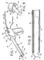
- the inventive tissue sampling probe 10comprises a tube 12 having a lumen 14.
- a cutter channel 16extends axially along the length of the tube outer wall 18 (Fig. 9).
- Extending axially through the cutter channel 16is an electrocautery cutter wire 20, preferably comprised of an electrically conductive shaped metallic memory wire, such as Nitinol, which comprises a proximal portion 22 and a distal portion 24.
- the cutter wire 20is preferably formed as a flattened round wire, because the resultant rectangular shape, which makes the wire stiff in the x-direction and flexible in the y-direction, is preferred for resisting lateral forces which are encountered as the wire is rotated in tissue.
- the tube 12preferably comprises an inner layer 25 and an outer layer 26 (Fig. 9), the inner layer 25 being preferably fabricated of a non-conductive radiolucent or radiodense biocompatible composite material, such as a glass filament wound epoxy impregnated matrix material.
- a non-conductive radiolucent or radiodense biocompatible composite materialsuch as a glass filament wound epoxy impregnated matrix material.
- HDPEhigh density polyethylene
- the tube 12preferably has a round cross-section, though other tube shapes may be used as well .
- Advantageous characteristics of the preferred composite materialinclude light weight, high melt temperature, high dielectric, ductility, non-conductivity, and machinability.
- An outer layer 26may be employed, the outer layer preferably comprising a high dielectric coating which is shrink wrapped about the outer diameter of the inner layer 25. Because the preferred material for the inner layer 25 is easily machinable, the channel 16 is preferably machined into the outer surface of inner layer 25.
- an actuator 27Disposed proximally of the tube 12 is an actuator 27, which preferably comprises a housing 28, a fixed handle 29, a cutter advancement slide knob 30, and an actuation switch 32.
- the housing 28encloses a variable speed electric motor 34 which is connected to a power supply via a power cord 36. Operation of the motor 34 drives interengaging gears 37 and 38, resulting in selective rotation of the tube 12.
- An important aspect of the inventionis the use of an electrocautery generator (not shown).
- the electrical energy from the electrocautery (electrosurgical) generatoris conducted along an electrical line 40 to the cutter wire 20, and is selectively activated or deactivated using the electrosurgical energy actuation switch 32.
- the electrical line 40is connected to an electrode advancement collar 41, which comprises an electrical contact brush 42 and an electrode ring 44.
- a proximal end 46 of the cutter wire (electrode) 20is attached to the electrode advancement collar.
- the cutter advancement slide knob 30is mechanically attached to the electrode advancement collar 41.
- the electrode 20is advanced distally when the cutter advancement slide knob 30 is moved distally.
- the slide knob 30 and the electrode advancement collar 41are electrically insulated from the cable 40, brush 42, and electrode ring 44.
- the electrocautery generatoris activated using the actuation switch 32 to electrically activate the cutter wire 20.
- the switch 32is preferably a momentary switch, which is actuated only when depressed and held by an operator. Simultaneously, the switch 32 actuates the motor 34 to cause the tube 12 to rotate at a relatively high rate of speed by means of gears 37, 3 8. Then, the tube 12 is advanced by the operator through tissue with the cutter wire 20 in its retracted position, as shown in Fig. 3, to obtain the desired tissue sample. With the wire 20 energized to function as an electrocautery cutter, the advancement of the rotating tube 12 easily slices through the tissue to create a tissue specimen 48 (Fig. 1) for capture within the lumen 14. In the preferred embodiment, depth marks (not shown) may be disposed axially along the exterior surface of the tube 12 in order to assist the physician in determining when the tube 12 has been advanced to the desired position.
- the energized conductive cutter wire 20functions to define and cut a tissue sample 48 having approximately the same internal diameter or cross-sectional shape as that of the tube 12.
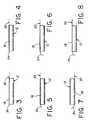
- the distal end of the tube 12receives the generally cylindrical tissue sample, which is created as the tube and cutter wire are energized, rotated, and axially advanced simultaneously.
- advancement of the tube 12is halted, and the cutter wire 20 is advanced distally relative to the tube 12 by sliding the cutter advancement slide knob 30 distally. Distal advancement of the cutter wire 20 is illustrated sequentially in Figs. 4, 5, and 6. As shown in Fig.
- the cutter wire 20is fully advanced so that the electrically energized distal end 24 is curved radially inwardly to sever a portion of the distal end 49 of the tissue specimen 48 (Fig. 2). While the wire 20 is in its fully advanced position, the tube 12 is rotated at a relatively slow rate of speed, by operation of the motor 34, until the tube 12 has been rotated at least 180 degrees, to the position illustrated in Fig. 7, and preferably 360 degrees, to the position illustrated in Fig. 8. In order to rotate the tube 12 at the second lower rate of speed, either the switch 32 may be actuated to a second operating position, or a second switch may be utilized.
- tissue specimenOnce the tissue specimen has been captured within the lumen 14, one or more additional samples may be obtained and accommodated within the lumen if desired.
- the instrumentWhen the desired tissue samples have been obtained, the instrument may be removed from the patient's body so that the tissue sample(s) may be extracted and examined.
- the interior surface of the tube 12may be coated to reduce frictional contact between the tube and the tissue sample as it travels through the lumen 14.
- a source of suctionvacuum
- a source of vacuum pressurewould be employed for drawing a vacuum through the primary lumen 14, so that the vacuum pressure in the primary lumen draws tissue to be sampled into the primary lumen as the electrosurgical cutting element 20 cuts the drawn tissue.
- the vacuum pressuremay then act to assist transport of the tissue specimen proximally through the primary lumen to a tissue receptacle.
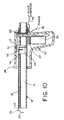
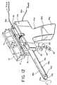
- a modified embodimentwhich is presently preferred, is illustrated in Figs. 11 and 12, wherein all elements corresponding to those of the embodiment of Figure 1 are designated by like reference numerals, succeeded by the letter "a".
- the modified actuation systemincludes a first actuation switch 32a, disposed on a proximal surface of the handle 29a, which is preferably a momentary switch (actuated only when physically depressed and held by the operator).
- the first actuation switch 32asimultaneously actuates the motor 34a to rotate the tube 12a at a relatively high rotational velocity, and energizes the cutter wire 20a for electrosurgical cutting.
- a cutter wire advancement trigger 50is provided distally of the handle 29a.
- the cutter wire advancement trigger 50is pivotally mounted, via pivot pin 52, to a fork 54, as illustrated in Figs. 11 and 12, and is attached at its upper end to an electrode advancement plate 56 (Fig. 11).
- Such attachment between the trigger 50 and the advancement plate 56may be by means of any conventionally known mechanical fastening system.
- the electrode advancement plateis slidably disposed on a carriage pin 58, and is disposed between an electrode carriage block 60 and a proximal surface 62 of the housing 28a, the carriage block 60 also being slidably disposed on the carriage pin 58.
- An upper portion 64 of the carriage block 60is fixedly attached to the electrode advancement collar 41a.
- a second actuation switch 66is disposed on the trigger 50.
- the switch 66is adapted to simultaneously energize the cutter wire 20a and to actuate the motor 34a to rotate the tube 12a, as is the first switch 32a, except that when the second switch is actuated, the motor operates at a lower speed to rotate the tube 12a at a relatively low rotational velocity.
- a biasing spring 68is disposed on the carriage pin 58, between the carriage block 60 and a distal portion 70 of the housing 28a, to bias the carriage block 60 proximally, so that the cutter wire (electrode) 20a is biased to its retracted position.
- the housing 28ais constructed to comprise a lid 72 which is attached by means of hinges 74 to the main housing portion 76 so that the housing 28a is openable to permit access to the entire tube portion 12a. When closed, the lid 72 is secured by a latch 78.
- the entire tube portion 12aas illustrated in Figs.
- the entire tube portion 12a, including the electrode advancement collar 41a and the gear 38a,is preferably constructed of disposable materials, such as biocompatible plastics or composite materials, so that it may be made disposable after a single use for a reasonable cost.
- a practitioner desiring to obtain a particular tissue sample from a patientmay grasp the handle 29a of the instrument 10a and move the instrument 10a toward the targeted entry point on the patient's body using known imaging techniques.
- switch 32ais actuated by the practitioner depressing and holding same so that the cutter wire 20a is energized and the motor 34a is simultaneously actuated to rotate the tube relatively quickly, in order to enhance the cutting process.
- the instrumentcontinues to be advanced through the patient's tissue, with the cutter wire 20a biased by spring 68 to its retracted position, as illustrated in Fig.
- tissue specimen 48a of a desired lengthis captured within the lumen 14a of the tube 12a.
- the entire distal end of the tube 12afunctions effectively as a cutting element to readily obtain a tissue sample core from the desired tissue area.
- depth marksmay be disposed axially along the exterior surface of the tube 12a to assist the physician in determining when the tube 12a has been advanced to the desired position.
- the energized conductive cutter wire 20afunctions to cut a tissue sample 44a having approximately the same diameter or cross-sectional shape as that of the inside diameter of tube 12a.
- This movement of the carriage block 60in turn causes the electrode advancement collar 41a to slide distally, thereby extending the electrode (cutter wire) 20a to its extended position, as shown in Figs. 12 and 13b.
- Contact of the electrode advancement plate 56 with the fork 54serves as a stop, to ensure that the cutter wire 20a is only advanced a desired distance to create the curved portion 24a for severing the distal end of the specimen 48a.
- the switch 66is simultaneously depressed, thereby actuating the motor 34a to rotate the tube 12a at a relatively slow rotational velocity, as opposed to the relatively high rotational velocity initiated by actuation of the switch 32a.
- Depression of the switch 66which is preferably a momentary switch (like switch 32a), also simultaneously energizes the cutter wire 20a to initiate an electrosurgical cutting capability.
- Applicantshave found that the ability to simultaneously advance the cutting wire 20a distally and to slowly rotate the tube 12a is beneficial to the tissue capture process, relative to the alternative of first extending the wire to its advanced position, and then initiating rotation of the tube 12a, which was originally thought to be necessary in order to prevent excessive lateral stresses (torque) on the cutting wire as it is being extended, due to the rotation of the tube 12a.
- the energized distal end 24a of the wire 20afunctions to sever the entire distal end 49 of the tissue specimen 48a, as in the first embodiment illustrated in Fig. 1.
- the tissue specimenis completely captured within the lumen 14a of the instrument 10a (Fig. 12), and the instrument may be withdrawn from the patient's body to retrieve the specimen for examination.
- a source of vacuumcould be employed to assist in drawing tissue into the tube 12a and/or to assist in transporting the tissue specimen proximally through the tube 12a into a tissue receptacle (not shown).
- the lid 72 of the housing 28amay be opened, and the used module 12a separated from the instrument and discarded as medical waste. Then, a new module 12a may be installed within the housing, and the lid secured in a closed position.
- the instrumentmay be used multiple times on the same patient without sterilization or replacement of the disposable module.
- a particularly advantageous aspect of the inventionis its ability to be used in connection with sensing probes for identifying and locating desired tissue to be sampled.
- ultrasound probes or radiation detecting (Geiger) probesmay be employed, such as those disclosed in U.S. Patent Nos. 4,959,547, 5,036,201, 5,119,818, 5,148,040, 5,170,055, and 5,246,005, which are assigned to Care Wise Medical Products Corporation of Morgan Hill, California, and are herein expressly incorporated by reference.
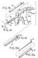
- Figs. 15-16bthe instrument 10a illustrated in Fig. 11 is shown, though the instrument 10 illustrated in Fig. 1 or other similar instruments could be substituted therefor.
- Figs. 15-16bthe instrument 10a illustrated in Fig. 11 is shown, though the instrument 10 illustrated in Fig. 1 or other similar instruments could be substituted therefor.
- Figs. 15-16bthe instrument 10a illustrated in Fig. 11 is shown, though the instrument 10 illustrated in Fig. 1 or other similar instruments could be substitute
- the proximal end 78 of the tube 12ais open, so that there is a sight line through the entire lumen 14a of the tube 12a, from the proximal end 78 to the distal end of the tube 12a.
- the proximal end 78may be configured to receive a sensing probe 80 or 82 (Figs. 15 and 16).
- a stand alone sensing probe 80is illustrated in Fig. 15, which may comprise either an ultrasonic probe or a geiger probe, both of which are conventionally known in the medical diagnostic arts.
- the probe 80is specifically configured to mate into the through hole 78 of the soft tissue acquisition device 10a.
- Electronic control lines 84extend from a proximal end of the probe 80 to appropriate control units, for receiving and processing information obtained by the probe.
- a multi-vision probesuch as the probe 82 illustrated in Fig. 16, may be utilized.
- This type of probeis capable of functioning both as an ultrasonic probe and as a geiger probe, and has two sets of control lines 86 and 88 for communicating with ultrasonic and geiger electronic control units, respectively.
- a lesion (tissue) 90 to be sampled(Fig. 15) is located using a multi-vision probe 82 or a combination of stand-alone probes 80, which are disposed in the soft tissue acquisition device 10a.
- the geiger portion of the probeprovides an X-Y location on the surface of the tissue to be sampled, while the ultrasonic portion provides depth information as well as X-Y location information.
- the soft tissue acquisition device 10ais held in position, while the sensing probe(s) is (are) removed. Following removal of the sensing probe, a tissue sample may be obtained using the methods described supra.
Landscapes
- Health & Medical Sciences (AREA)
- Life Sciences & Earth Sciences (AREA)
- Surgery (AREA)
- Engineering & Computer Science (AREA)
- Biomedical Technology (AREA)
- Veterinary Medicine (AREA)
- Medical Informatics (AREA)
- Molecular Biology (AREA)
- Heart & Thoracic Surgery (AREA)
- Animal Behavior & Ethology (AREA)
- General Health & Medical Sciences (AREA)
- Public Health (AREA)
- Pathology (AREA)
- Physics & Mathematics (AREA)
- Plasma & Fusion (AREA)
- Nuclear Medicine, Radiotherapy & Molecular Imaging (AREA)
- Otolaryngology (AREA)
- Surgical Instruments (AREA)
- Sampling And Sample Adjustment (AREA)
Abstract
Description
Claims (20)
- A tissue sampling apparatus, comprising:a tubular body having a primary lumen for receiving a tissue sample, andhaving a distal end and a proximal end; andan electrosurgical cutting element disposed along an axial length of said tubularbody, said cutting element including a distal cutting end and having an axially extendedposition and an axially retracted position relative to said tubular body.
- The tissue sampling apparatus recited in Claim 1, wherein theelectrosurgical cutting element comprises a wire.
- The tissue sampling apparatus recited in Claim 2, wherein the wirecomprises an electrically conductive shaped metallic memory wire.
- The tissue sampling apparatus recited in Claim 2, wherein the wirecross-section comprises a rectangular shape.
- The tissue sampling apparatus recited in Claim 1, wherein said tubularbody comprises an outer wall, said outer wall having a cutter channel disposed therein,said electrosurgical cutting element being disposed within said cutter channel.
- The tissue sampling apparatus recited in Claim 1, wherein the tubularbody is comprised of a non-electrically conductive material.
- The tissue sampling apparatus as recited in Claim 1, wherein saidtubular body lumen is adapted to accommodate a plurality of tissue samples.
- The tissue sampling apparatus as recited in Claim 1, and furthercomprising a coating on the interior surface of the tubular body to facilitate transport of tissue samples therethrough.
- The tissue sampling apparatus as recited in Claim 1, and furthercomprising depth marks on said tubular body to facilitate positioning of the apparatus ina patient's body.
- The tissue sampling apparatus as recited in Claim 1, wherein a distalportion of the cutting element is curved radially to extend across a portion of the cross-sectionalarea of said lumen when the cutting element is in said axially extendedposition.
- The tissue sampling apparatus as recited in Claim 1, and furthercomprising a first actuation switch for energizing said electrosurgical cutting elementand rotating said tubular body at a first higher rotational velocity when saidelectrosurgical cutting element is in said axially retracted position, and a secondactuation switch for energizing said electrosurgical cutting element and rotating saidtubular body at a second lower rotational velocity when said electrosurgical cuttingelement is in said axially extended position.
- The tissue sampling apparatus as recited in Claim 1, and furthercomprising a pivotable trigger, said trigger being adapted to move said electrosurgicalcutting element to the axially extended position and to simultaneously rotate saidtubular body at a relatively low rotational velocity.
- The tissue sampling apparatus as recited in Claim 1, wherein said tissuesampling apparatus further comprises a housing, said housing having a lid portionwhich is openable relative to a remaining housing portion, said tubular body beingremovable from said housing for ready disposal after a single use.
- The tissue sampling apparatus as recited in Claim 13, wherein said tubular body is constructed of inexpensive disposable plastic material.
- A tissue sampling apparatus, comprising:a tubular body having a primary lumen for receiving a tissue sample, andhaving a distal end and a proximal end, said tubular body being comprised of disposablematerials;an electrosurgical cutting element disposed along an axial length of said tubularbody;a housing for enclosing a portion of the tubular body, the housing comprising alid portion which is openable relative to a body portion thereof;said tubular body being removable from said housing and readily replaceable byanother tubular body between medical procedures.
- The tissue sampling apparatus recited in claim 15, wherein saidelectrosurgical cutting element comprises a wire which is selectively extendible andretractable along an axis of said tubular body.
- The tissue sampling apparatus recited in claim 16, wherein a distal endof said wire curves in a direction generally transverse to said axis when the wire isextended distally.
- A method of capturing a body tissue sample using a tissue samplingapparatus comprising a tubular body having a lumen extending therethrough and a distalend, an electrosurgical cutting element having a distal end portion which is disposeddistally of the distal end of the tubular body, and an actuator for moving the cuttingelement, the method comprising:energizing the electrosurgical cutting element;rotating the tubular body at a relatively high rate of speed;advancing the tubular body through a tissue portion a desired distance so thatthe energized electrosurgical element cuts a tissue sample core as the tissue sample enters the lumen;advancing the electrosurgical cutting element so that said distal end portionextends radially inwardly across a portion of a distal end of said tissue sample core; androtating the tubular body at a relatively low rate of speed, so that the distal endportion of the electrosurgical cutting element severs said tissue sample core from saidtissue portion.
- The method as recited in claim 18, wherein the electrosurgical cuttingelement is advanced to said extended position and the tubular body is rotated at saidrelatively low rate of speed simultaneously.
- The method as recited in claim 18, and further comprising the steps ofremoving the tubular body from the apparatus at the conclusion of a medical procedure,and installing a new tubular body prior to the commencement of another medicalprocedure.
Applications Claiming Priority (2)
| Application Number | Priority Date | Filing Date | Title |
|---|---|---|---|
| US08/786,497US5913857A (en) | 1996-08-29 | 1997-01-21 | Methods and devices for collection of soft tissue |
| US786497 | 1997-01-21 |
Publications (3)
| Publication Number | Publication Date |
|---|---|
| EP0858774A2true EP0858774A2 (en) | 1998-08-19 |
| EP0858774A3 EP0858774A3 (en) | 1998-09-16 |
| EP0858774B1 EP0858774B1 (en) | 2005-08-03 |
Family
ID=25138768
Family Applications (1)
| Application Number | Title | Priority Date | Filing Date |
|---|---|---|---|
| EP98300372AExpired - LifetimeEP0858774B1 (en) | 1997-01-21 | 1998-01-20 | Devices for collection of soft tissue |
Country Status (7)
| Country | Link |
|---|---|
| US (1) | US5913857A (en) |
| EP (1) | EP0858774B1 (en) |
| JP (1) | JP3955374B2 (en) |
| AU (1) | AU719017B2 (en) |
| CA (1) | CA2227348C (en) |
| DE (1) | DE69831027T2 (en) |
| ES (1) | ES2245473T3 (en) |
Cited By (17)
| Publication number | Priority date | Publication date | Assignee | Title |
|---|---|---|---|---|
| WO2000044295A1 (en)* | 1999-01-27 | 2000-08-03 | Senorx, Inc. | Tissue specimen isolating and damaging device and method |
| US6743228B2 (en) | 2001-09-12 | 2004-06-01 | Manoa Medical, Inc. | Devices and methods for tissue severing and removal |
| US6955676B2 (en) | 1999-06-22 | 2005-10-18 | Senorx, Inc. | Shaped scalpel |
| EP1035801A4 (en)* | 1997-11-18 | 2005-10-26 | Care Wise Medical Products Cor | Minimally invasive surgical probe for tissue identification and retrieval and method of use |
| US6997885B2 (en) | 1998-04-08 | 2006-02-14 | Senorx, Inc. | Dilation devices and methods for removing tissue specimens |
| US7819819B2 (en) | 2003-02-24 | 2010-10-26 | Senorx, Inc. | Biopsy device with inner cutting member |
| US7981051B2 (en) | 2005-08-05 | 2011-07-19 | Senorx, Inc. | Biopsy device with fluid delivery to tissue specimens |
| WO2011123446A1 (en)* | 2010-03-30 | 2011-10-06 | Flatland Martin L | Tissue excision device |
| EP2438867A3 (en)* | 2010-10-05 | 2012-05-02 | Trokamed GmbH | Medical instrument |
| US8282573B2 (en) | 2003-02-24 | 2012-10-09 | Senorx, Inc. | Biopsy device with selectable tissue receiving aperture orientation and site illumination |
| US8317725B2 (en) | 2005-08-05 | 2012-11-27 | Senorx, Inc. | Biopsy device with fluid delivery to tissue specimens |
| US8343071B2 (en) | 2004-12-16 | 2013-01-01 | Senorx, Inc. | Biopsy device with aperture orientation and improved tip |
| US9216012B2 (en) | 1998-09-01 | 2015-12-22 | Senorx, Inc | Methods and apparatus for securing medical instruments to desired locations in a patient's body |
| US9408592B2 (en) | 2003-12-23 | 2016-08-09 | Senorx, Inc. | Biopsy device with aperture orientation and improved tip |
| US9750487B2 (en) | 2005-05-23 | 2017-09-05 | Senorx, Inc. | Tissue cutting member for a biopsy device |
| WO2019154523A1 (en)* | 2018-02-12 | 2019-08-15 | Norwegian University Of Science And Technology (Ntnu) | Surgical cutting tool |
| KR20210133694A (en)* | 2020-04-29 | 2021-11-08 | 연세대학교 산학협력단 | Inspection apparatus for breast |
Families Citing this family (157)
| Publication number | Priority date | Publication date | Assignee | Title |
|---|---|---|---|---|
| JPH10508504A (en) | 1994-09-16 | 1998-08-25 | バイオプシス メディカル インコーポレイテッド | Method and apparatus for identifying and marking tissue |
| US5882316A (en)* | 1996-08-29 | 1999-03-16 | City Of Hope | Minimally invasive biopsy device |
| US6436116B1 (en) | 1997-10-06 | 2002-08-20 | Smith & Nephew, Inc. | Methods and apparatus for removing veins |
| US6344026B1 (en)* | 1998-04-08 | 2002-02-05 | Senorx, Inc. | Tissue specimen encapsulation device and method thereof |
| US6517498B1 (en)* | 1998-03-03 | 2003-02-11 | Senorx, Inc. | Apparatus and method for tissue capture |
| US6875182B2 (en) | 1998-03-03 | 2005-04-05 | Senorx, Inc. | Electrosurgical specimen-collection system |
| US6638234B2 (en) | 1998-03-03 | 2003-10-28 | Senorx, Inc. | Sentinel node location and biopsy |
| US6540695B1 (en) | 1998-04-08 | 2003-04-01 | Senorx, Inc. | Biopsy anchor device with cutter |
| US6296639B1 (en)* | 1999-02-12 | 2001-10-02 | Novacept | Apparatuses and methods for interstitial tissue removal |
| US6679851B2 (en)* | 1998-09-01 | 2004-01-20 | Senorx, Inc. | Tissue accessing and anchoring device and method |
| US20080146965A1 (en) | 2003-08-11 | 2008-06-19 | Salvatore Privitera | Surgical Device for The Collection of Soft Tissue |
| US20010047183A1 (en) | 2000-04-05 | 2001-11-29 | Salvatore Privitera | Surgical device for the collection of soft tissue |
| CA2287087C (en)* | 1998-10-23 | 2007-12-04 | Ethicon Endo-Surgery, Inc. | Surgical device for the collection of soft tissue |
| US6036698A (en) | 1998-10-30 | 2000-03-14 | Vivant Medical, Inc. | Expandable ring percutaneous tissue removal device |
| JP4559630B2 (en)* | 1998-11-25 | 2010-10-13 | ユナイテッド ステイツ サージカル コーポレイション | Biopsy system |
| US9669113B1 (en) | 1998-12-24 | 2017-06-06 | Devicor Medical Products, Inc. | Device and method for safe location and marking of a biopsy cavity |
| US6356782B1 (en) | 1998-12-24 | 2002-03-12 | Vivant Medical, Inc. | Subcutaneous cavity marking device and method |
| US6371904B1 (en) | 1998-12-24 | 2002-04-16 | Vivant Medical, Inc. | Subcutaneous cavity marking device and method |
| US6159209A (en)* | 1999-03-18 | 2000-12-12 | Canox International Ltd. | Automatic resectoscope |
| US6193715B1 (en)* | 1999-03-19 | 2001-02-27 | Medical Scientific, Inc. | Device for converting a mechanical cutting device to an electrosurgical cutting device |
| US6162187A (en)* | 1999-08-02 | 2000-12-19 | Ethicon Endo-Surgery, Inc. | Fluid collection apparatus for a surgical device |
| US6280398B1 (en)* | 1999-10-18 | 2001-08-28 | Ethicon Endo-Surgery | Methods and devices for collection of soft tissue |
| US6471659B2 (en) | 1999-12-27 | 2002-10-29 | Neothermia Corporation | Minimally invasive intact recovery of tissue |
| US6325801B1 (en)* | 1999-12-04 | 2001-12-04 | Karl Storz Gmbh & Co. Kg | Instrument for severing tissue with HF current |
| US6277083B1 (en) | 1999-12-27 | 2001-08-21 | Neothermia Corporation | Minimally invasive intact recovery of tissue |
| WO2001060235A2 (en)* | 2000-02-18 | 2001-08-23 | Fogarty Thomas J M D | Improved device for accurately marking tissue |
| US6564806B1 (en)* | 2000-02-18 | 2003-05-20 | Thomas J. Fogarty | Device for accurately marking tissue |
| US6293945B1 (en)* | 2000-03-06 | 2001-09-25 | Everest Medical Corporation | Electrosurgical instrument with suction capability |
| US6512943B1 (en) | 2000-05-22 | 2003-01-28 | Wisconsin Alumni Research Foundation | Combined ultrasound-radionuclide device for percutaneous ultrasound-guided biopsy and method of use |
| US6881209B2 (en)* | 2000-05-25 | 2005-04-19 | Cook Incorporated | Medical device including unitary, continuous portion of varying durometer |
| US6494844B1 (en) | 2000-06-21 | 2002-12-17 | Sanarus Medical, Inc. | Device for biopsy and treatment of breast tumors |
| WO2002005717A1 (en)* | 2000-07-18 | 2002-01-24 | Senorx, Inc. | Apparatus and method for tissue capture |
| DE60117398T2 (en) | 2000-09-24 | 2006-10-12 | Medtronic, Inc., Minneapolis | SURGICAL MICRO RESEARCH INSTRUMENT WITH ELECTROCAUTERISATION FEATURE |
| AU2002211568B2 (en)* | 2000-10-16 | 2005-11-17 | Sanarus Medical, Inc. | Device for biopsy of tumors |
| US6540694B1 (en) | 2000-10-16 | 2003-04-01 | Sanarus Medical, Inc. | Device for biopsy tumors |
| WO2002069808A2 (en) | 2000-11-06 | 2002-09-12 | Suros Surgical Systems, Inc. | Biopsy apparatus |
| US7458940B2 (en) | 2000-11-06 | 2008-12-02 | Suros Surgical Systems, Inc. | Biopsy apparatus |
| US6758824B1 (en)* | 2000-11-06 | 2004-07-06 | Suros Surgical Systems, Inc. | Biopsy apparatus |
| US6673023B2 (en)* | 2001-03-23 | 2004-01-06 | Stryker Puerto Rico Limited | Micro-invasive breast biopsy device |
| US20020138091A1 (en)* | 2001-03-23 | 2002-09-26 | Devonrex, Inc. | Micro-invasive nucleotomy device and method |
| US20020138021A1 (en)* | 2001-03-23 | 2002-09-26 | Devonrex, Inc. | Micro-invasive tissue removal device |
| US6589240B2 (en) | 2001-08-28 | 2003-07-08 | Rex Medical, L.P. | Tissue biopsy apparatus with collapsible cutter |
| US6623437B2 (en) | 2001-08-28 | 2003-09-23 | Rex Medical, L.P. | Tissue biopsy apparatus |
| US6605047B2 (en)* | 2001-09-10 | 2003-08-12 | Vivant Medical, Inc. | Biopsy marker delivery system |
| US8109885B2 (en) | 2002-03-19 | 2012-02-07 | C. R. Bard, Inc. | Biopsy device for removing tissue specimens using a vacuum |
| EP1524940B1 (en) | 2002-03-19 | 2011-08-24 | Bard Dublin ITC Limited | Biopsy device and biopsy needle module that can be inserted into the biopsy device |
| US7247161B2 (en)* | 2002-03-22 | 2007-07-24 | Gyrus Ent L.L.C. | Powered surgical apparatus, method of manufacturing powered surgical apparatus, and method of using powered surgical apparatus |
| DE20305093U1 (en)* | 2003-03-29 | 2003-09-11 | Heske, Norbert F., 82288 Kottgeisering | Coaxial cannula with sealing element |
| DE10314240B4 (en) | 2003-03-29 | 2025-05-28 | Bard Dublin Itc Ltd. | Pressure generation unit |
| WO2004091471A2 (en)* | 2003-04-04 | 2004-10-28 | Berger, Constance, F. | Apparatus for heating bottles and method of manufacturing same |
| WO2004098382A2 (en)* | 2003-05-01 | 2004-11-18 | Sherwood Services Ag | Suction coagulator with dissecting probe |
| US6955653B2 (en)* | 2003-07-30 | 2005-10-18 | Neothermia Corporation | Electrosurgical method and apparatus with dense tissue recovery capacity |
| US7988642B2 (en) | 2003-10-14 | 2011-08-02 | Suros Surgical Systems, Inc. | Vacuum assisted biopsy device |
| US8048003B2 (en) | 2003-10-14 | 2011-11-01 | Suros Surgical Systems, Inc. | Vacuum assisted biopsy device |
| JP4500315B2 (en) | 2003-10-14 | 2010-07-14 | シュロス・サージカル・システムズ・インコーポレーテッド | Vacuum assisted biopsy needle set |
| US6979332B2 (en)* | 2003-11-04 | 2005-12-27 | Medtronic, Inc. | Surgical micro-resecting instrument with electrocautery and continuous aspiration features |
| US7402140B2 (en)* | 2004-02-12 | 2008-07-22 | Sanarus Medical, Inc. | Rotational core biopsy device with liquid cryogen adhesion probe |
| US20050203441A1 (en)* | 2004-03-12 | 2005-09-15 | Voegele James W. | Electrode sleeve for biopsy device |
| US7465279B2 (en)* | 2004-03-31 | 2008-12-16 | Ethicon Endo-Surgery, Inc. | Marker device and method of deploying a cavity marker using a surgical biopsy device |
| US8568334B2 (en)* | 2004-05-11 | 2013-10-29 | Inrad, Inc. | Core biopsy device |
| CA2506961C (en)* | 2004-05-11 | 2013-05-07 | Inrad, Inc. | Core biopsy device |
| US8932233B2 (en)* | 2004-05-21 | 2015-01-13 | Devicor Medical Products, Inc. | MRI biopsy device |
| US7708751B2 (en) | 2004-05-21 | 2010-05-04 | Ethicon Endo-Surgery, Inc. | MRI biopsy device |
| US9638770B2 (en) | 2004-05-21 | 2017-05-02 | Devicor Medical Products, Inc. | MRI biopsy apparatus incorporating an imageable penetrating portion |
| JP4814229B2 (en) | 2004-07-09 | 2011-11-16 | バード ペリフェラル ヴァスキュラー インコーポレイテッド | Transport device for biopsy device |
| US8062230B1 (en)* | 2004-10-14 | 2011-11-22 | Suros Surgical Systems, Inc. | Surgical site marker delivery system |
| US20090204021A1 (en)* | 2004-12-16 | 2009-08-13 | Senorx, Inc. | Apparatus and method for accessing a body site |
| US7517321B2 (en) | 2005-01-31 | 2009-04-14 | C. R. Bard, Inc. | Quick cycle biopsy system |
| US8449477B2 (en)* | 2005-03-02 | 2013-05-28 | Dune Medical Devices Ltd. | Device and method for transporting and handling tissue |
| ATE538737T1 (en)* | 2005-04-15 | 2012-01-15 | Cook Medical Technologies Llc | LINE EXTRACTION DEVICE |
| US10653440B2 (en)* | 2005-04-15 | 2020-05-19 | Cook Medical Technologies Llc | Tip for lead extraction device |
| US7556622B2 (en)* | 2005-05-18 | 2009-07-07 | Suros Surgical Systems, Inc. | Selectively openable tissue filter |
| ES2539578T3 (en) | 2005-08-10 | 2015-07-02 | C.R. Bard, Inc. | Multi-sample biopsy device and single insert with various transport systems |
| EP1921998B8 (en) | 2005-08-10 | 2021-07-07 | C.R.Bard, Inc. | Single-insertion, multiple sampling biopsy device with linear drive |
| JP4991723B2 (en) | 2005-08-10 | 2012-08-01 | シー・アール・バード・インコーポレーテッド | Single insertion multiple sampling biopsy device with integrated marker |
| US20070055173A1 (en)* | 2005-08-23 | 2007-03-08 | Sanarus Medical, Inc. | Rotational core biopsy device with liquid cryogen adhesion probe |
| JP2007229330A (en)* | 2006-03-03 | 2007-09-13 | Toshka Inc | Device and handpiece for hair transplant |
| US20070232954A1 (en)* | 2006-04-04 | 2007-10-04 | Harris Jeffrey P | Automated skin biopsy device |
| EP3417792B1 (en) | 2006-08-21 | 2022-03-02 | C. R. Bard, Inc. | Self-contained handheld biopsy needle |
| EP1897506B1 (en)* | 2006-09-08 | 2010-03-03 | Ethicon Endo-Surgery, Inc. | A surgical instrument for performing controlled myotomies |
| SI2086418T1 (en) | 2006-10-06 | 2011-05-31 | Bard Peripheral Vascular Inc | Tissue handling system with reduced operator exposure |
| US8262586B2 (en) | 2006-10-24 | 2012-09-11 | C. R. Bard, Inc. | Large sample low aspect ratio biopsy needle |
| US20080103412A1 (en) | 2006-11-01 | 2008-05-01 | Yem Chin | Removing Tissue |
| US20080125782A1 (en)* | 2006-11-29 | 2008-05-29 | Disc Dynamics, Inc. | Method and apparatus for removing an extension from a prosthesis |
| US20140039343A1 (en) | 2006-12-13 | 2014-02-06 | Devicor Medical Products, Inc. | Biopsy system |
| US7981049B2 (en)* | 2006-12-13 | 2011-07-19 | Devicor Medical Products, Inc. | Engagement interface for biopsy system vacuum module |
| US8480595B2 (en) | 2006-12-13 | 2013-07-09 | Devicor Medical Products, Inc. | Biopsy device with motorized needle cocking |
| US8251916B2 (en) | 2006-12-13 | 2012-08-28 | Devicor Medical Products, Inc. | Revolving tissue sample holder for biopsy device |
| US9345457B2 (en) | 2006-12-13 | 2016-05-24 | Devicor Medical Products, Inc. | Presentation of biopsy sample by biopsy device |
| US20130324882A1 (en) | 2012-05-30 | 2013-12-05 | Devicor Medical Products, Inc. | Control for biopsy device |
| US8702623B2 (en)* | 2008-12-18 | 2014-04-22 | Devicor Medical Products, Inc. | Biopsy device with discrete tissue chambers |
| US7938786B2 (en)* | 2006-12-13 | 2011-05-10 | Devicor Medical Products, Inc. | Vacuum timing algorithm for biopsy device |
| US8414587B2 (en)* | 2007-01-26 | 2013-04-09 | Laurimed, Llc | Styli used to position device for carrying out selective discetomy |
| US8088119B2 (en)* | 2007-02-01 | 2012-01-03 | Laurimed, Llc | Methods and devices for treating tissue |
| US8795197B2 (en) | 2007-07-17 | 2014-08-05 | Histologics, LLC | Frictional trans-epithelial tissue disruption collection apparatus and method of inducing an immune response |
| WO2009012392A1 (en) | 2007-07-17 | 2009-01-22 | Neal Marc Lonky | Frictional trans-epithelial tissue disruption and collection apparatus and method of inducing and/or augmenting an immune response |
| US20090076412A1 (en)* | 2007-09-13 | 2009-03-19 | Boston Scientific Scimed, Inc. | Apparatus and Methods for Obtaining a Sample of Tissue |
| US8808200B2 (en) | 2007-10-01 | 2014-08-19 | Suros Surgical Systems, Inc. | Surgical device and method of using same |
| US8202229B2 (en) | 2007-10-01 | 2012-06-19 | Suros Surgical Systems, Inc. | Surgical device |
| US8454531B2 (en) | 2007-11-20 | 2013-06-04 | Devicor Medical Products, Inc. | Icon-based user interface on biopsy system control module |
| US8052616B2 (en)* | 2007-11-20 | 2011-11-08 | Devicor Medical Products, Inc. | Biopsy device with fine pitch drive train |
| US20090131819A1 (en)* | 2007-11-20 | 2009-05-21 | Ritchie Paul G | User Interface On Biopsy Device |
| US7806835B2 (en)* | 2007-11-20 | 2010-10-05 | Devicor Medical Products, Inc. | Biopsy device with sharps reduction feature |
| US7858038B2 (en)* | 2007-11-20 | 2010-12-28 | Devicor Medical Products, Inc. | Biopsy device with illuminated tissue holder |
| US9039634B2 (en)* | 2007-11-20 | 2015-05-26 | Devicor Medical Products, Inc. | Biopsy device tissue sample holder rotation control |
| US20090131821A1 (en)* | 2007-11-20 | 2009-05-21 | Speeg Trevor W V | Graphical User Interface For Biopsy System Control Module |
| US7575556B2 (en)* | 2007-11-20 | 2009-08-18 | Ethicon Endo-Surgery, Inc. | Deployment device interface for biopsy device |
| US8241225B2 (en) | 2007-12-20 | 2012-08-14 | C. R. Bard, Inc. | Biopsy device |
| US7854706B2 (en) | 2007-12-27 | 2010-12-21 | Devicor Medical Products, Inc. | Clutch and valving system for tetherless biopsy device |
| US10820825B2 (en) | 2008-10-22 | 2020-11-03 | Cornell University | Method and device for evaluation of local tissue's biological or biomechanical character |
| US20100160777A1 (en)* | 2008-12-22 | 2010-06-24 | Hardin Terry D | Reverse deployment device |
| WO2010107424A1 (en) | 2009-03-16 | 2010-09-23 | C.R. Bard, Inc. | Biopsy device having rotational cutting |
| AU2009344276B2 (en) | 2009-04-15 | 2014-06-05 | C.R. Bard, Inc. | Biopsy apparatus having integrated fluid management |
| US8206316B2 (en) | 2009-06-12 | 2012-06-26 | Devicor Medical Products, Inc. | Tetherless biopsy device with reusable portion |
| US8529468B2 (en) | 2009-07-01 | 2013-09-10 | Suros Surgical Systems, Inc. | Surgical system |
| US8465471B2 (en) | 2009-08-05 | 2013-06-18 | Rocin Laboratories, Inc. | Endoscopically-guided electro-cauterizing power-assisted fat aspiration system for aspirating visceral fat tissue within the abdomen of a patient |
| US8348929B2 (en) | 2009-08-05 | 2013-01-08 | Rocin Laboratories, Inc. | Endoscopically-guided tissue aspiration system for safely removing fat tissue from a patient |
| US9173641B2 (en) | 2009-08-12 | 2015-11-03 | C. R. Bard, Inc. | Biopsy apparatus having integrated thumbwheel mechanism for manual rotation of biopsy cannula |
| US8485989B2 (en) | 2009-09-01 | 2013-07-16 | Bard Peripheral Vascular, Inc. | Biopsy apparatus having a tissue sample retrieval mechanism |
| US8430824B2 (en) | 2009-10-29 | 2013-04-30 | Bard Peripheral Vascular, Inc. | Biopsy driver assembly having a control circuit for conserving battery power |
| US8283890B2 (en) | 2009-09-25 | 2012-10-09 | Bard Peripheral Vascular, Inc. | Charging station for battery powered biopsy apparatus |
| US8597206B2 (en) | 2009-10-12 | 2013-12-03 | Bard Peripheral Vascular, Inc. | Biopsy probe assembly having a mechanism to prevent misalignment of components prior to installation |
| US9044213B1 (en) | 2010-03-26 | 2015-06-02 | Histologics, LLC | Frictional tissue sampling and collection method and device |
| US8685052B2 (en) | 2010-06-30 | 2014-04-01 | Laurimed, Llc | Devices and methods for cutting tissue |
| CN103068327B (en) | 2010-06-30 | 2015-08-05 | 劳瑞弥徳有限责任公司 | For excising and withdraw from the apparatus and method of tissue |
| US8734445B2 (en) | 2010-09-07 | 2014-05-27 | Covidien Lp | Electrosurgical instrument with sealing and dissection modes and related methods of use |
| US9649490B2 (en) | 2011-06-16 | 2017-05-16 | Cook Medical Technologies Llc | Tip for lead extraction device |
| WO2013119336A1 (en)* | 2012-02-10 | 2013-08-15 | Laurimed, Llc | Vacuum powered rotary devices and methods |
| US11351369B2 (en)* | 2012-04-25 | 2022-06-07 | Medtronic Xomed, Inc. | Stimulation probe for robotic and laparoscopic surgery |
| US9113901B2 (en) | 2012-05-14 | 2015-08-25 | Covidien Lp | Modular surgical instrument with contained electrical or mechanical systems |
| CA2876545C (en) | 2012-06-14 | 2021-03-30 | Sanoculis Ltd. | A medical device, assembly and method for creating a channel in soft tissue |
| US10201332B1 (en) | 2012-12-03 | 2019-02-12 | Healoe Llc | Device and method of orienting a biopsy device on epithelial tissue |
| US9259211B2 (en)* | 2012-12-24 | 2016-02-16 | Transmed7, Llc | Automated, selectable, soft tissue excision biopsy devices and methods |
| CA2902221A1 (en) | 2013-03-20 | 2014-09-25 | Bard Peripheral Vascular, Inc. | Biopsy device |
| US9586041B2 (en) | 2013-08-26 | 2017-03-07 | Cook Medical Technologies Llc | Enhanced outer sheath for extraction device |
| ES2726985T3 (en) | 2013-11-05 | 2019-10-11 | Bard Inc C R | Biopsy device that has integrated vacuum |
| US8815099B1 (en) | 2014-01-21 | 2014-08-26 | Laurimed, Llc | Devices and methods for filtering and/or collecting tissue |
| WO2016015233A1 (en) | 2014-07-30 | 2016-02-04 | Covidien Lp | Surgical instruments capable of being selectively disassembled to facilitate replacement of disposable components and/or sterilization of reusable components |
| US10080571B2 (en) | 2015-03-06 | 2018-09-25 | Warsaw Orthopedic, Inc. | Surgical instrument and method |
| WO2016178656A1 (en) | 2015-05-01 | 2016-11-10 | C. R. Bard, Inc. | Biopsy device |
| US11013466B2 (en) | 2016-01-28 | 2021-05-25 | Healoe, Llc | Device and method to control and manipulate a catheter |
| IL269091B2 (en)* | 2017-03-08 | 2024-04-01 | Momentis Surgical Ltd | Electrosurgery device |
| IL251684B (en) | 2017-04-09 | 2019-01-31 | Tel Hashomer Medical Res Infrastructure & Services Ltd | Device and method for creating a canal in soft tissue |
| US11793498B2 (en) | 2017-05-19 | 2023-10-24 | Merit Medical Systems, Inc. | Biopsy needle devices and methods of use |
| US11844500B2 (en) | 2017-05-19 | 2023-12-19 | Merit Medical Systems, Inc. | Semi-automatic biopsy needle device and methods of use |
| US11116483B2 (en) | 2017-05-19 | 2021-09-14 | Merit Medical Systems, Inc. | Rotating biopsy needle |
| CN110141358B (en)* | 2018-02-12 | 2024-04-16 | 崔建春 | Endoscopic sheath electric excision biopsy device for breast tube |
| EP3806756B1 (en) | 2018-06-13 | 2024-01-03 | Stryker European Operations Limited | Bone fragment collector and processor |
| US11103273B2 (en)* | 2018-12-14 | 2021-08-31 | Rasim Kakony | Powered hair restoration and surgical assembly |
| KR20210125513A (en)* | 2019-02-11 | 2021-10-18 | 싱가포르 헬스 서비시즈 피티이 엘티디 | skin biopsy device |
| SE543196C2 (en)* | 2019-05-29 | 2020-10-20 | Szafran Biopsy Ab | A biopsy tool for removing a tissue sample |
| US11712313B2 (en)* | 2019-07-23 | 2023-08-01 | Siemens Medical Solutions Usa, Inc. | Dual manipulation for robotic catheter system |
| US12295556B2 (en) | 2019-09-27 | 2025-05-13 | Merit Medical Systems, Inc. | Rotation biopsy system and handle |
| US12150627B2 (en) | 2019-12-11 | 2024-11-26 | Merit Medical Systems, Inc. | Bone biopsy device and related methods |
| EP4076290B1 (en) | 2019-12-18 | 2024-07-31 | Stryker European Operations Limited | Bone fragment collector and processor |
| CN114983491B (en)* | 2022-06-10 | 2024-09-13 | 苏州市美新迪斯医疗科技有限公司 | Biopsy needle, biopsy needle set and bone marrow biopsy device |
| CN115462842B (en)* | 2022-09-30 | 2024-08-30 | 哈尔滨理工大学 | Mammary gland rotary-cut biopsy device with water conservancy diversion function |
Citations (2)
| Publication number | Priority date | Publication date | Assignee | Title |
|---|---|---|---|---|
| US5111828A (en) | 1990-09-18 | 1992-05-12 | Peb Biopsy Corporation | Device for percutaneous excisional breast biopsy |
| US5526822A (en) | 1994-03-24 | 1996-06-18 | Biopsys Medical, Inc. | Method and apparatus for automated biopsy and collection of soft tissue |
Family Cites Families (42)
| Publication number | Priority date | Publication date | Assignee | Title |
|---|---|---|---|---|
| US2113246A (en)* | 1937-05-17 | 1938-04-05 | Wappler Frederick Charles | Endoscopic forceps |
| AT290712B (en)* | 1969-06-30 | 1971-06-11 | Hubert Dr Reinisch | Biopsy collection device |
| US3850162A (en)* | 1972-07-03 | 1974-11-26 | J Iglesias | Endoscope with continuous irrigation |
| JPS5917290Y2 (en)* | 1979-06-04 | 1984-05-21 | オリンパス光学工業株式会社 | High frequency knife for endoscope |
| US4311145A (en)* | 1979-07-16 | 1982-01-19 | Neomed, Inc. | Disposable electrosurgical instrument |
| GB2053691B (en)* | 1979-07-24 | 1983-04-27 | Wolf Gmbh Richard | Endoscopes |
| DE3148306A1 (en)* | 1981-12-03 | 1983-06-30 | Karl Fritz 1000 Berlin Reich | Hollow needle set with system |
| WO1983003343A1 (en)* | 1982-03-31 | 1983-10-13 | ALLARD, Jan, Hakan | A device for taking tissue samples |
| US4750488A (en)* | 1986-05-19 | 1988-06-14 | Sonomed Technology, Inc. | Vibration apparatus preferably for endoscopic ultrasonic aspirator |
| DE3632197A1 (en)* | 1986-09-23 | 1988-03-31 | Rainer Dr Hofmann | Punching or cutting biopsy cannula |
| US5201731A (en)* | 1988-03-30 | 1993-04-13 | Hakky Said I | Laser resectoscope with ultransonic imaging means |
| NL8801002A (en)* | 1988-04-18 | 1989-11-16 | V O F Metrias | INJECTION WASHER. |
| US5159925A (en)* | 1988-09-09 | 1992-11-03 | Gynelab, Inc. | Cauterizing apparatus and method for laparoscopic cholecystostomy, gallbladder ablation and treatment of benign prostate hypertrophy |
| JP2656955B2 (en)* | 1988-09-14 | 1997-09-24 | オリンパス光学工業株式会社 | Radiation detection and treatment device |
| GB8822492D0 (en)* | 1988-09-24 | 1988-10-26 | Considine J | Apparatus for removing tumours from hollow organs of body |
| DE3916161A1 (en)* | 1989-05-18 | 1990-11-22 | Wolf Gmbh Richard | ELECTROSURGICAL INSTRUMENT |
| GB8928302D0 (en)* | 1989-12-14 | 1990-02-21 | Clinical Product Dev Ltd | Biopsy instruments |
| EP0448857A1 (en)* | 1990-03-27 | 1991-10-02 | Jong-Khing Huang | An apparatus of a spinning type of resectoscope for prostatectomy |
| US5047027A (en)* | 1990-04-20 | 1991-09-10 | Everest Medical Corporation | Tumor resector |
| US5078716A (en)* | 1990-05-11 | 1992-01-07 | Doll Larry F | Electrosurgical apparatus for resecting abnormal protruding growth |
| US5195958A (en)* | 1990-05-25 | 1993-03-23 | Phillips Edward H | Tool for laparoscopic surgery |
| US5201741A (en)* | 1990-07-24 | 1993-04-13 | Andrew Surgical, Inc. | Surgical snare with shape memory effect wire |
| US5133360A (en)* | 1991-03-07 | 1992-07-28 | Spears Colin P | Spears retriever |
| US5395312A (en)* | 1991-10-18 | 1995-03-07 | Desai; Ashvin | Surgical tool |
| US5322503A (en)* | 1991-10-18 | 1994-06-21 | Desai Ashvin H | Endoscopic surgical instrument |
| US5186714A (en)* | 1992-05-18 | 1993-02-16 | Yab Revo-Tech Inc. | Multifunctional surgical instrument |
| US5221281A (en)* | 1992-06-30 | 1993-06-22 | Valleylab Inc. | Electrosurgical tubular trocar |
| US5282800A (en)* | 1992-09-18 | 1994-02-01 | Edward Weck, Inc. | Surgical instrument |
| CA2106039A1 (en)* | 1992-09-23 | 1994-03-24 | David A. Nicholas | Surgical biopsy forceps apparatus |
| US5401272A (en)* | 1992-09-25 | 1995-03-28 | Envision Surgical Systems, Inc. | Multimodality probe with extendable bipolar electrodes |
| US5312327A (en)* | 1992-10-09 | 1994-05-17 | Symbiosis Corporation | Cautery override safety systems endoscopic electrosurgical suction-irrigation instrument |
| US5360427A (en)* | 1992-12-18 | 1994-11-01 | Heshmat Majlessi | Retractable electro-suction device |
| US5403311A (en)* | 1993-03-29 | 1995-04-04 | Boston Scientific Corporation | Electro-coagulation and ablation and other electrotherapeutic treatments of body tissue |
| US5375608A (en)* | 1993-04-21 | 1994-12-27 | Tiefenbrun; Jonathan | Method and instrument assembly for use in obtaining biopsy |
| US5348555A (en)* | 1993-04-26 | 1994-09-20 | Zinnanti William J | Endoscopic suction, irrigation and cautery instrument |
| US5304124A (en)* | 1993-06-07 | 1994-04-19 | Essig Mitchell N | Myoma removal technique |
| DE4323585A1 (en)* | 1993-07-14 | 1995-01-19 | Delma Elektro Med App | Bipolar high-frequency surgical instrument |
| JP3691060B2 (en)* | 1993-09-20 | 2005-08-31 | ボストン・サイエンティフィック・コーポレーション | Multi-action specimen collection device for multiple biopsies |
| JP3647863B2 (en)* | 1993-09-20 | 2005-05-18 | ボストン・サイエンティフィック・コーポレーション | Multiple biopsy specimen extraction device |
| CA2172129A1 (en)* | 1993-09-20 | 1995-04-06 | Bruce H. Diamond | Multiple biopsy sampling device |
| US5437665A (en)* | 1993-10-12 | 1995-08-01 | Munro; Malcolm G. | Electrosurgical loop electrode instrument for laparoscopic surgery |
| US5649547A (en)* | 1994-03-24 | 1997-07-22 | Biopsys Medical, Inc. | Methods and devices for automated biopsy and collection of soft tissue |
- 1997
- 1997-01-21USUS08/786,497patent/US5913857A/ennot_activeExpired - Lifetime
- 1998
- 1998-01-06AUAU50361/98Apatent/AU719017B2/ennot_activeCeased
- 1998-01-19CACA002227348Apatent/CA2227348C/ennot_activeExpired - Fee Related
- 1998-01-20ESES98300372Tpatent/ES2245473T3/ennot_activeExpired - Lifetime
- 1998-01-20EPEP98300372Apatent/EP0858774B1/ennot_activeExpired - Lifetime
- 1998-01-20DEDE69831027Tpatent/DE69831027T2/ennot_activeExpired - Lifetime
- 1998-01-21JPJP00944298Apatent/JP3955374B2/ennot_activeExpired - Fee Related
Patent Citations (2)
| Publication number | Priority date | Publication date | Assignee | Title |
|---|---|---|---|---|
| US5111828A (en) | 1990-09-18 | 1992-05-12 | Peb Biopsy Corporation | Device for percutaneous excisional breast biopsy |
| US5526822A (en) | 1994-03-24 | 1996-06-18 | Biopsys Medical, Inc. | Method and apparatus for automated biopsy and collection of soft tissue |
Cited By (47)
| Publication number | Priority date | Publication date | Assignee | Title |
|---|---|---|---|---|
| EP1035801A4 (en)* | 1997-11-18 | 2005-10-26 | Care Wise Medical Products Cor | Minimally invasive surgical probe for tissue identification and retrieval and method of use |
| US6997885B2 (en) | 1998-04-08 | 2006-02-14 | Senorx, Inc. | Dilation devices and methods for removing tissue specimens |
| US7357801B2 (en) | 1998-04-08 | 2008-04-15 | Senorx, Inc. | Tissue specimen isolating and damaging device and method |
| US7651467B2 (en) | 1998-04-08 | 2010-01-26 | Senorx, Inc | Dilation devices and methods for removing tissue specimens |
| US9216012B2 (en) | 1998-09-01 | 2015-12-22 | Senorx, Inc | Methods and apparatus for securing medical instruments to desired locations in a patient's body |
| US9510809B2 (en) | 1999-01-27 | 2016-12-06 | Senorx, Inc. | Tissue specimen isolating and damaging device and method |
| WO2000044295A1 (en)* | 1999-01-27 | 2000-08-03 | Senorx, Inc. | Tissue specimen isolating and damaging device and method |
| US6955676B2 (en) | 1999-06-22 | 2005-10-18 | Senorx, Inc. | Shaped scalpel |
| US7572256B2 (en) | 1999-06-22 | 2009-08-11 | Senorx, Inc. | Shaped scalpel |
| US6743228B2 (en) | 2001-09-12 | 2004-06-01 | Manoa Medical, Inc. | Devices and methods for tissue severing and removal |
| US10172595B2 (en) | 2003-02-24 | 2019-01-08 | Senorx, Inc. | Biopsy device with selectable tissue receiving aperture orientation and site illumination |
| US10335127B2 (en) | 2003-02-24 | 2019-07-02 | Senorx, Inc. | Biopsy device with selectable tissue receiving aperature orientation and site illumination |
| US8282573B2 (en) | 2003-02-24 | 2012-10-09 | Senorx, Inc. | Biopsy device with selectable tissue receiving aperture orientation and site illumination |
| US7819819B2 (en) | 2003-02-24 | 2010-10-26 | Senorx, Inc. | Biopsy device with inner cutting member |
| US11534147B2 (en) | 2003-02-24 | 2022-12-27 | Senorx, Inc. | Biopsy device with a removable sample recieving cartridge |
| US11589849B2 (en) | 2003-02-24 | 2023-02-28 | Senorx, Inc. | Biopsy device with selectable tissue receiving aperature orientation and site illumination |
| US10231715B2 (en) | 2003-02-24 | 2019-03-19 | Senorx, Inc. | Biopsy device with inner cutting member |
| US9408592B2 (en) | 2003-12-23 | 2016-08-09 | Senorx, Inc. | Biopsy device with aperture orientation and improved tip |
| US8360990B2 (en) | 2004-12-16 | 2013-01-29 | Senorx, Inc. | Biopsy device with aperture orientation and improved tip |
| US10105125B2 (en) | 2004-12-16 | 2018-10-23 | Senorx, Inc. | Biopsy device with aperture orientation and improved tip |
| US8343071B2 (en) | 2004-12-16 | 2013-01-01 | Senorx, Inc. | Biopsy device with aperture orientation and improved tip |
| US10478161B2 (en) | 2005-05-23 | 2019-11-19 | Senorx, Inc. | Tissue cutting member for a biopsy device |
| US11426149B2 (en) | 2005-05-23 | 2022-08-30 | SenoRx., Inc. | Tissue cutting member for a biopsy device |
| US9750487B2 (en) | 2005-05-23 | 2017-09-05 | Senorx, Inc. | Tissue cutting member for a biopsy device |
| US10874381B2 (en) | 2005-08-05 | 2020-12-29 | Senorx, Inc. | Biopsy device with fluid delivery to tissue specimens |
| US7981051B2 (en) | 2005-08-05 | 2011-07-19 | Senorx, Inc. | Biopsy device with fluid delivery to tissue specimens |
| US10064609B2 (en) | 2005-08-05 | 2018-09-04 | Senorx, Inc. | Method of collecting one or more tissue specimens |
| US8915864B2 (en) | 2005-08-05 | 2014-12-23 | Senorx, Inc. | Biopsy device with fluid delivery to tissue specimens |
| US8317725B2 (en) | 2005-08-05 | 2012-11-27 | Senorx, Inc. | Biopsy device with fluid delivery to tissue specimens |
| US8597200B2 (en) | 2010-03-30 | 2013-12-03 | Siteselect Medial Technologies, Inc. | Tissue excision device |
| US8529467B2 (en) | 2010-03-30 | 2013-09-10 | Siteselect Medical Technologies, Inc. | Tissue excision device with a collapsible stylet |
| WO2011123446A1 (en)* | 2010-03-30 | 2011-10-06 | Flatland Martin L | Tissue excision device |
| US8740809B2 (en) | 2010-03-30 | 2014-06-03 | Siteselect Medical Technologies, Inc. | Tissue excision device with a retractable backhook |
| US8597201B2 (en) | 2010-03-30 | 2013-12-03 | Siteselect Medical Technologies, Inc. | Tissue excision device with a flexible transection blade |
| US8597204B2 (en) | 2010-03-30 | 2013-12-03 | Siteselect Medical Technologies, Inc. | Tissue excision device with an independent needle |
| US8597203B2 (en) | 2010-03-30 | 2013-12-03 | Siteselect Medical Technologies, Inc. | Tissue excision device with a reduced diameter cannula |
| US8597202B2 (en) | 2010-03-30 | 2013-12-03 | Siteselect Medical Technologies, Inc. | Tissue excision device with a modified cutting edge |
| US8535240B2 (en) | 2010-03-30 | 2013-09-17 | Siteselect Medical Technologies, Inc. | Tissue excision device with a retracting stylet blade |
| US9226733B2 (en) | 2010-03-30 | 2016-01-05 | Siteselect Medical Technologies, Inc. | Tissue excision device with an independent needle |
| US8444573B2 (en) | 2010-03-30 | 2013-05-21 | Siteselect Medical Technologies, Inc. | Tissue excision device |
| US8529466B2 (en) | 2010-03-30 | 2013-09-10 | Siteselect Medical Technologies, Inc. | Tissue excision device with rotating stylet blades |
| US8485988B2 (en) | 2010-03-30 | 2013-07-16 | Siteselect Medical Technologies, Inc. | Tissue excision device |
| EP2438867A3 (en)* | 2010-10-05 | 2012-05-02 | Trokamed GmbH | Medical instrument |
| US9144432B2 (en) | 2010-10-05 | 2015-09-29 | Trokamed Gmbh | Medical instrument |
| WO2019154523A1 (en)* | 2018-02-12 | 2019-08-15 | Norwegian University Of Science And Technology (Ntnu) | Surgical cutting tool |
| KR20210133694A (en)* | 2020-04-29 | 2021-11-08 | 연세대학교 산학협력단 | Inspection apparatus for breast |
| KR20220097372A (en)* | 2020-04-29 | 2022-07-07 | 연세대학교 산학협력단 | Apparatus and Method for Cutting and Retrieving Breast Specimen |
Also Published As
| Publication number | Publication date |
|---|---|
| CA2227348A1 (en) | 1998-07-21 |
| EP0858774A3 (en) | 1998-09-16 |
| EP0858774B1 (en) | 2005-08-03 |
| AU719017B2 (en) | 2000-05-04 |
| DE69831027D1 (en) | 2005-09-08 |
| US5913857A (en) | 1999-06-22 |
| CA2227348C (en) | 2004-09-28 |
| JPH10201764A (en) | 1998-08-04 |
| ES2245473T3 (en) | 2006-01-01 |
| AU5036198A (en) | 1998-07-23 |
| DE69831027T2 (en) | 2006-04-13 |
| JP3955374B2 (en) | 2007-08-08 |
Similar Documents
| Publication | Publication Date | Title |
|---|---|---|
| US5913857A (en) | Methods and devices for collection of soft tissue | |
| CA2262552C (en) | Methods and devices for collection of soft tissue | |
| EP1093757B1 (en) | Device for collection of soft tissue | |
| US7229439B2 (en) | Apparatus and method for accessing a body site | |
| US7488295B2 (en) | Tissue acquisition system and method of use | |
| EP1249209B1 (en) | Biopsy instrument with tissue marking element | |
| US6050955A (en) | Biopsy apparatus and method | |
| EP0939604A1 (en) | Control system and method for automated biopsy device | |
| WO2002062231A2 (en) | Biopsy apparatus and method |
Legal Events
| Date | Code | Title | Description |
|---|---|---|---|
| PUAI | Public reference made under article 153(3) epc to a published international application that has entered the european phase | Free format text:ORIGINAL CODE: 0009012 | |
| PUAL | Search report despatched | Free format text:ORIGINAL CODE: 0009013 | |
| AK | Designated contracting states | Kind code of ref document:A2 Designated state(s):DE ES FR GB IT | |
| AX | Request for extension of the european patent | Free format text:AL;LT;LV;MK;RO;SI | |
| AK | Designated contracting states | Kind code of ref document:A3 Designated state(s):AT BE CH DE DK ES FI FR GB GR IE IT LI LU MC NL PT SE | |
| AX | Request for extension of the european patent | Free format text:AL;LT;LV;MK;RO;SI | |
| RTI1 | Title (correction) | ||
| PUAL | Search report despatched | Free format text:ORIGINAL CODE: 0009013 | |
| AX | Request for extension of the european patent | Free format text:AL;LT;LV;MK;RO;SI | |
| RTI1 | Title (correction) | ||
| 17P | Request for examination filed | Effective date:19990527 | |
| AKX | Designation fees paid | Free format text:DE ES FR GB IT | |
| 17Q | First examination report despatched | Effective date:20021031 | |
| GRAP | Despatch of communication of intention to grant a patent | Free format text:ORIGINAL CODE: EPIDOSNIGR1 | |
| GRAS | Grant fee paid | Free format text:ORIGINAL CODE: EPIDOSNIGR3 | |
| GRAA | (expected) grant | Free format text:ORIGINAL CODE: 0009210 | |
| AK | Designated contracting states | Kind code of ref document:B1 Designated state(s):DE ES FR GB IT | |
| REG | Reference to a national code | Ref country code:GB Ref legal event code:FG4D | |
| RIC1 | Information provided on ipc code assigned before grant | Ipc:7A 61B 17/32 B Ipc:7A 61B 10/00 A | |
| REF | Corresponds to: | Ref document number:69831027 Country of ref document:DE Date of ref document:20050908 Kind code of ref document:P | |
| REG | Reference to a national code | Ref country code:ES Ref legal event code:FG2A Ref document number:2245473 Country of ref document:ES Kind code of ref document:T3 | |
| ET | Fr: translation filed | ||
| PLBE | No opposition filed within time limit | Free format text:ORIGINAL CODE: 0009261 | |
| STAA | Information on the status of an ep patent application or granted ep patent | Free format text:STATUS: NO OPPOSITION FILED WITHIN TIME LIMIT | |
| 26N | No opposition filed | Effective date:20060504 | |
| PGFP | Annual fee paid to national office [announced via postgrant information from national office to epo] | Ref country code:ES Payment date:20100128 Year of fee payment:13 | |
| PGFP | Annual fee paid to national office [announced via postgrant information from national office to epo] | Ref country code:GB Payment date:20100120 Year of fee payment:13 | |
| REG | Reference to a national code | Ref country code:GB Ref legal event code:732E Free format text:REGISTERED BETWEEN 20101209 AND 20101215 | |
| REG | Reference to a national code | Ref country code:GB Ref legal event code:732E Free format text:REGISTERED BETWEEN 20110203 AND 20110209 | |
| REG | Reference to a national code | Ref country code:FR Ref legal event code:TP | |
| PGFP | Annual fee paid to national office [announced via postgrant information from national office to epo] | Ref country code:IT Payment date:20110126 Year of fee payment:14 Ref country code:DE Payment date:20110127 Year of fee payment:14 | |
| GBPC | Gb: european patent ceased through non-payment of renewal fee | Effective date:20110120 | |
| PG25 | Lapsed in a contracting state [announced via postgrant information from national office to epo] | Ref country code:GB Free format text:LAPSE BECAUSE OF NON-PAYMENT OF DUE FEES Effective date:20110120 | |
| REG | Reference to a national code | Ref country code:ES Ref legal event code:FD2A Effective date:20120220 | |
| REG | Reference to a national code | Ref country code:DE Ref legal event code:R082 Ref document number:69831027 Country of ref document:DE Representative=s name:BOEHMERT & BOEHMERT ANWALTSPARTNERSCHAFT MBB -, DE Effective date:20120216 Ref country code:DE Ref legal event code:R082 Ref document number:69831027 Country of ref document:DE Representative=s name:BOEHMERT & BOEHMERT, DE Effective date:20120216 Ref country code:DE Ref legal event code:R081 Ref document number:69831027 Country of ref document:DE Owner name:DEVICOR MEDICAL PRODUCTS, INC., PLEASANT PRAIR, US Free format text:FORMER OWNER: ETHICON ENDO-SURGERY, INC., CINCINNATI, OHIO, US Effective date:20120216 Ref country code:DE Ref legal event code:R081 Ref document number:69831027 Country of ref document:DE Owner name:DEVICOR MEDICAL PRODUCTS, INC., US Free format text:FORMER OWNER: ETHICON ENDO-SURGERY, INC., CINCINNATI, US Effective date:20120216 | |
| PG25 | Lapsed in a contracting state [announced via postgrant information from national office to epo] | Ref country code:ES Free format text:LAPSE BECAUSE OF NON-PAYMENT OF DUE FEES Effective date:20110121 | |
| REG | Reference to a national code | Ref country code:GB Ref legal event code:732E Free format text:REGISTERED BETWEEN 20120726 AND 20120801 | |
| PG25 | Lapsed in a contracting state [announced via postgrant information from national office to epo] | Ref country code:DE Free format text:LAPSE BECAUSE OF NON-PAYMENT OF DUE FEES Effective date:20120801 | |
| REG | Reference to a national code | Ref country code:DE Ref legal event code:R119 Ref document number:69831027 Country of ref document:DE Effective date:20120801 | |
| PG25 | Lapsed in a contracting state [announced via postgrant information from national office to epo] | Ref country code:IT Free format text:LAPSE BECAUSE OF NON-PAYMENT OF DUE FEES Effective date:20120120 | |
| PGFP | Annual fee paid to national office [announced via postgrant information from national office to epo] | Ref country code:FR Payment date:20130211 Year of fee payment:16 | |
| REG | Reference to a national code | Ref country code:FR Ref legal event code:ST Effective date:20140930 | |
| PG25 | Lapsed in a contracting state [announced via postgrant information from national office to epo] | Ref country code:FR Free format text:LAPSE BECAUSE OF NON-PAYMENT OF DUE FEES Effective date:20140131 |