EP0858066A1 - Method and device for converting the digital image rate - Google Patents
Method and device for converting the digital image rateDownload PDFInfo
- Publication number
- EP0858066A1 EP0858066A1EP98200158AEP98200158AEP0858066A1EP 0858066 A1EP0858066 A1EP 0858066A1EP 98200158 AEP98200158 AEP 98200158AEP 98200158 AEP98200158 AEP 98200158AEP 0858066 A1EP0858066 A1EP 0858066A1
- Authority
- EP
- European Patent Office
- Prior art keywords
- frames
- images
- input
- rate
- output
- Prior art date
- Legal status (The legal status is an assumption and is not a legal conclusion. Google has not performed a legal analysis and makes no representation as to the accuracy of the status listed.)
- Withdrawn
Links
Images


Classifications
- H—ELECTRICITY
- H04—ELECTRIC COMMUNICATION TECHNIQUE
- H04N—PICTORIAL COMMUNICATION, e.g. TELEVISION
- H04N7/00—Television systems
- H04N7/01—Conversion of standards, e.g. involving analogue television standards or digital television standards processed at pixel level
- G—PHYSICS
- G06—COMPUTING OR CALCULATING; COUNTING
- G06F—ELECTRIC DIGITAL DATA PROCESSING
- G06F3/00—Input arrangements for transferring data to be processed into a form capable of being handled by the computer; Output arrangements for transferring data from processing unit to output unit, e.g. interface arrangements
- G06F3/14—Digital output to display device ; Cooperation and interconnection of the display device with other functional units
- G06F3/153—Digital output to display device ; Cooperation and interconnection of the display device with other functional units using cathode-ray tubes
- G—PHYSICS
- G09—EDUCATION; CRYPTOGRAPHY; DISPLAY; ADVERTISING; SEALS
- G09G—ARRANGEMENTS OR CIRCUITS FOR CONTROL OF INDICATING DEVICES USING STATIC MEANS TO PRESENT VARIABLE INFORMATION
- G09G2340/00—Aspects of display data processing
- G09G2340/04—Changes in size, position or resolution of an image
- G09G2340/0407—Resolution change, inclusive of the use of different resolutions for different screen areas
- G09G2340/0435—Change or adaptation of the frame rate of the video stream
- G—PHYSICS
- G09—EDUCATION; CRYPTOGRAPHY; DISPLAY; ADVERTISING; SEALS
- G09G—ARRANGEMENTS OR CIRCUITS FOR CONTROL OF INDICATING DEVICES USING STATIC MEANS TO PRESENT VARIABLE INFORMATION
- G09G3/00—Control arrangements or circuits, of interest only in connection with visual indicators other than cathode-ray tubes
- G09G3/20—Control arrangements or circuits, of interest only in connection with visual indicators other than cathode-ray tubes for presentation of an assembly of a number of characters, e.g. a page, by composing the assembly by combination of individual elements arranged in a matrix no fixed position being assigned to or needed to be assigned to the individual characters or partial characters
- G09G3/2007—Display of intermediate tones
- G09G3/2018—Display of intermediate tones by time modulation using two or more time intervals
- G09G3/2022—Display of intermediate tones by time modulation using two or more time intervals using sub-frames
- G09G3/2025—Display of intermediate tones by time modulation using two or more time intervals using sub-frames the sub-frames having all the same time duration
Definitions
- the inventionrelates to a method and a device for converting digital signals to convert frame rate input at an output image rate, said input images being formed of input data frames.
- Such method and devicehave important applications in the field of moving image transmission, especially to view images on a television screen from a device with a crystal display screen liquids.
- Other applications of the inventionare conceivable such as the videophone, remote monitoring systems or Digital TV.
- Liquid crystal or LCD screens(Liquid Cristal Display) available in the devices commercial electronics are generally intended for display alphanumeric information or still images but are unsuitable for cinematic images. Indeed, the bit rate on an LCD, of the order of 3 to 6 images per second, is too weak to give a good visual reproduction of moving images and a unpleasant effect of jerks appears. To get good quality of moving pictures, the display rate must be higher or equal to 25 frames per second. On the other hand, the small size of Common LCDs do not provide sufficient image accuracy for application to moving pictures.
- An object of the inventionis therefore to provide a means to increase the bit rate of images intended to be displayed on a LCD to make this bit rate compatible with the bit rate of the images video.
- this methodgenerates a a number of drawbacks.
- the low flow rate provided by the LCD systemimplies that successive moving pictures are temporally quite distant from each other and are therefore significantly different.
- the repetition of these images to increasing the number (therefore the flow)remains effective for visualizing still images but not for moving images which, moreover, are distant in time.
- the succession of images thus constructedprovides a visual impression of discontinuity in movement, what the present invention proposes to make less noticeable.
- a method of genre already mentionedis remarkable in that the step of calculating average is preceded by a decision step to trigger the calculation of an arithmetic mean over a plurality of frames stored.
- the device shown in Figure 1consists a telephone 1 provided with an LCD display system connected to a display monitor 2 (here a television) to display on monitor 2 of the images originally intended for the LCD.
- a display monitor 2here a television
- a video imageis made up of two frames intertwined. Since the scanning frequency of a TV is generally close to 50 Hertz, the video frame rate is therefore 25 frames per second. However, an image on an LCD is displayed after 16 successive scans of 76,800 (320 * 240) pixels of the screen. An image displayed on an LCD therefore consists of 16 non-interlaced frames.
- the scanning frequency of an LCDvarying between 50 and 100 Hertz, its flow can vary between 3 and 6 frames per second. This low flow explains that the LCDs are not suitable for still images only.
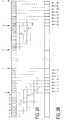
- Figure 2shows the format of a digital image for an LCD. It consists of 16 frames, denoted t 1 to t 16 , corresponding to the 16 successive scans of the screen. Each frame contains data relating to the state of all the pixels of the screen, at a given instant. Each pixel of the LCD is therefore likely to be excited with each scan, that is to say from 0 to 16 times to constitute an image.
- the binary nature of the pixelsrequires averaging over a large number of frames before displaying the result on the screen if we want to observe an acceptable level of detail on a monochrome image.
- the 16 screensmake it possible to obtain a visual impression of 16 gray levels while each pixel can only be in two states, excited or inactive, which corresponds to only two shades.
- the imagesbeing temporally spaced from the time necessary for 16 consecutive scans, the "average" state of a pixel during 16 scans (representing a point of the visual image) is likely to vary greatly from one image to another.
- the data frames representing the state of each pixel at a given timeare supplied at a frequency included between 50 and 100 Hertz. As for the bitrate, it is only 3 to 6 images per second. This offset stems from the fact that we must wait 16 data frames before being able to display an image complete on the LCD screen.
- the principle of the inventionconsists in exploiting the frame data as they are received for produce new digital images intended to increase the output frame rate. For this, we use a method of calculation commonly used in many fields where intervenes smoothing of numerical values. This is the calculation of averages slippery, applied here to image processing. We calculate the sliding average of the pixel states over the last 16 frames received, the result of each averaging producing a new image. This calculation can be performed with each new frame received or every 2, 3, owing, 15 frames, depending on the desired output frame rate.
- a new imageis produced every two frames.
- the calculation of the average of the states of the pixels over the last 16 framesprovides a complete image and renewing the operation as soon as we have received 2 new frames we obtain other distinct images.
- the input frame rateis proportional to the frame rate of input data with a proportionality coefficient equal to 1/16. A flow rate 8 times greater than the flow rate is thus obtained at the outlet. original input images (or twice less than the bit rate of frames), i.e. a rate of 24 to 48 images per second.
- the maximum bit rate of 96 frames per second can be obtained by this processis achieved if we produce an image at each frame received but it requires very computational power higher than that necessary to obtain a bit rate of 48 images per second.
- a 48 frames per second output rateis more than enough to meet the television standard which requires only 25.
- FIG. 3The process is illustrated in Figure 3.
- Aare shown the original images consisting respectively of 16 data frames, displayed on an LCD at the rate of 6 images per second.
- In Bare represented the output images taken at the rate of 48 images per second from the original images.
- Figure 3illustrates in particular the system start-up phase.
- the first averageis calculated on the first 16 frames of data received, referenced t 1 to t 16 and the result constitutes the first available image.
- the last 14 of these previously received framesthat is to say the frames t 3 to t 16 , as well as the following two frames t 17 and t 18 .
- the average of the frames t 3 to t 18is then calculated to construct the second available image.
- the frames t 1 and t 2are then lost. All the images are thus constructed. For example, the tenth image comes from the calculation of the average of the frames t 19 to t 25 , the frames t 1 to t 18 being lost.
- the method according to the inventionprovides a means simple and advantageous for artificially increasing the flow output images without changing the structure of the input data nor require additional data.
- V1is the sum of frames t 1 and t 2 , V2 of frames t 3 and t 4 , etc.
- the average of frames t 1 to t 16 represented in the table by R ( ⁇ )is calculated at time ⁇ , that of frames t 3 to t 18 represented by R ( ⁇ + 1) is calculated at time ⁇ + 1 and that of the frames t 5 to t 20 represented by R ( ⁇ + 2) is calculated at time ⁇ + 2.
- the flowchart in Figure 4breaks down the different process steps (K0 to K9). This can be advantageously implanted in computer-controlled systems, or in integrated electronic circuits for use in small appliances.
- a first preliminary step to the process (K0)consists of initializing an iteration index k to zero and initialize at 1 a variable i used to number the frames received.
- a second preliminary stage (K1)initializes to 100,000 a time variable T.
- a storage step (K2)adds an increment to the index k and stores, under the variables V1 to V9, the sums of consecutive input data frames taken in pairs, so that each frame t i to t i + 17 is only taken into account once.
- step (K4)for calculating the sliding average of the frames.
- the calculation of the sliding average described aboveis briefly recalled in the organization chart with instructions K4 and K5. Then we subtract a unit to the variable T (K6).
- the final result Mk of the calculation of meanis stored under variable A representing an image digital to be taken at the rate set by the flow output images. The process is then repeated in step K2.
- step K8the classical calculation (K8) of the arithmetic mean of the variables V1 to V8 is carried out equivalent to the arithmetic mean of the 16 frames t i to t i + 15 during processing.
- the result ⁇ k (K9)is stored under the sampled variable A (as in step K7) at the rate set by the output image rate to be displayed on a monitor. The process is then repeated in step K1.
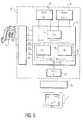
- the calculationsare made by a programmable logic circuit of the FPGA type (Field Programmable Gate Array).
- Information representing data frames, originally intended for the LCDare sent in FPGA input through specific ports F, L, C, D0, D1, D2 and D3.
- Frepresents the frame synchronization signal FRAME on the LCD screen which validates the screen display of each frame.
- Lrepresents the LOAD signal for validation of each of the 240 lines of the screen.
- Cis the clock signal CKD which validates the data D0 to D3 representing the information of 4 adjacent pixels on a screen line.
- the data framesare stored in random access memories 11 and 12 of RAM (Random Access Memory) type.
- the frames with an even index t 2iare stored in memory 11 and the frames with an odd index t 2i + 1 are stored in memory 12.
- a calculation unit 14performs the sums of two successive frames, one coming from memory 11 and the other from memory 12 to provide the VX data.
- a display memory 22makes it possible to store the images calculated using the averages taken at the output of the calculation cells 17 and 18.
- a display interface 24transmits the stored images to a video format setting device and displays them on the monitor 2.
Landscapes
- Engineering & Computer Science (AREA)
- Theoretical Computer Science (AREA)
- Human Computer Interaction (AREA)
- Physics & Mathematics (AREA)
- General Engineering & Computer Science (AREA)
- General Physics & Mathematics (AREA)
- Multimedia (AREA)
- Signal Processing (AREA)
- Transforming Electric Information Into Light Information (AREA)
- Television Systems (AREA)
- Controls And Circuits For Display Device (AREA)
- Liquid Crystal Display Device Control (AREA)
Abstract
Description
Translated fromFrenchL'invention concerne un procédé et un dispositif deconversion de signaux numériques pour convertir un débit d'imagesd'entrée en un débit d'images de sortie, lesdites images d'entréeétant formées de trames de données d'entrée.The invention relates to a method and a device forconverting digital signals to convert frame rateinput at an output image rate, said input imagesbeing formed of input data frames.
De tels procédé et dispositif ont d'importantesapplications dans le domaine de la transmission d'images animées,notamment pour visualiser sur un écran de télévision des imagesprovenant d'un dispositif muni d'un écran d'affichage à cristauxliquides. D'autres applications de l'invention sont envisageablescomme le visiophone, les systèmes de télésurveillance ou latélévision numérique.Such method and device have importantapplications in the field of moving image transmission,especially to view images on a television screenfrom a device with a crystal display screenliquids. Other applications of the invention are conceivablesuch as the videophone, remote monitoring systems orDigital TV.
Les écrans d'affichage à cristaux liquides ou LCD(Liquid Cristal Display) disponibles dans les dispositifsélectroniques du commerce sont généralement destinés à l'affichaged'informations alphanumériques ou d'images fixes mais sontinadaptés aux images cinématiques. En effet, le débit d'images surun LCD, de l'ordre de 3 à 6 images par seconde, est trop faiblepour donner une bonne restitution visuelle des images mobiles et uneffet désagréable de saccades apparaít. Pour obtenir une bonnequalité d'images animées, le débit d'affichage doit être supérieurou égal à 25 images par seconde. D'autre part, la petite taille desLCD usuels ne permet pas d'obtenir une précision d'image suffisantepour une application à des images animées.Liquid crystal or LCD screens(Liquid Cristal Display) available in the devicescommercial electronics are generally intended for displayalphanumeric information or still images but areunsuitable for cinematic images. Indeed, the bit rate onan LCD, of the order of 3 to 6 images per second, is too weakto give a good visual reproduction of moving images and aunpleasant effect of jerks appears. To get goodquality of moving pictures, the display rate must be higheror equal to 25 frames per second. On the other hand, the small size ofCommon LCDs do not provide sufficient image accuracyfor application to moving pictures.
C'est pourquoi il est intéressant de pouvoir augmenterle débit d'images originellement destinées à un LCD, de 3 à 6images par seconde, pour les visualiser confortablement, à l'aided'un moniteur de visualisation (notamment un téléviseur) alimentépar 25 images minimum par seconde.This is why it is interesting to be able to increasethe bit rate of images originally intended for an LCD, from 3 to 6frames per second, to view them comfortably, usinga display monitor (in particular a television) poweredby 25 frames minimum per second.
Un objet de l'invention est donc de fournir un moyenpour augmenter le débit d'images destinées à être affichées sur unLCD afin de rendre ce débit compatible avec le débit des imagesvidéo.An object of the invention is therefore to provide a meansto increase the bit rate of images intended to be displayed on aLCD to make this bit rate compatible with the bit rate of the imagesvideo.
Une méthode du type présenté ci-dessus est connue dudocument EP 0701368A2. Bien qu'orienté vers une applicationdifférente de celle envisagée dans la présente demande, ce documentdivulgue le principe selon lequel le débit d'images numériquesfourni par un dispositif de visualisation électronique peut êtreaugmenté artificiellement en combinant les données d'entrée dudispositif. La méthode décrite repose sur un principe de répétitiondes images constituées des données d'entrée pour obtenir en sortieun débit d'images supérieur à celui fourni par la successiond'exemplaires uniques de chaque image.A method of the type presented above is known fromdocument EP 0701368A2. Although oriented towards an applicationdifferent from that envisaged in this application, this documentdiscloses the principle that the digital frame rateprovided by an electronic display device can beartificially augmented by combining the input data from thedevice. The method described is based on a principle of repetitionimages made up of input data to obtain outputa higher bit rate than that provided by the estateunique copies of each image.
Pour notre application cette méthode engendre uncertain nombre d'inconvénients. En effet, le faible débit fournipar le système LCD implique que les images animées successives sonttemporellement assez éloignées les unes des autres et sont doncsensiblement différentes. La répétition de ces images pour enaugmenter le nombre (donc le débit) reste efficace pour visualiserdes images fixes mais pas pour des images animées qui, de plus,sont éloignées dans le temps. En effet, la succession d'imagesainsi construites procure une impression visuelle de discontinuitédans le mouvement, ce que la présente invention propose de rendremoins perceptible.For our application this method generates aa number of drawbacks. Indeed, the low flow rate providedby the LCD system implies that successive moving pictures aretemporally quite distant from each other and are thereforesignificantly different. The repetition of these images toincreasing the number (therefore the flow) remains effective for visualizingstill images but not for moving images which, moreover,are distant in time. Indeed, the succession of imagesthus constructed provides a visual impression of discontinuityin movement, what the present invention proposes to makeless noticeable.
Pour cela, un procédé du type mentionné dans lepréambule est caractérisé en ce qu'il comporte :
- une étape de stockage pour mémoriser des trames de donnéesd'entrée,
- une étape de calcul de moyenne pour fournir une moyenneglissante calculée sur une pluralité de trames stockées,
- une étape de prélèvement desdites moyennes pour fournir lesimages de sortie à un rythme fixé par le débit d'images de sortie.
- a storage step for storing frames of input data,
- an averaging step for providing a sliding average calculated over a plurality of stored frames,
- a step of sampling said means to provide the output images at a rate fixed by the output image rate.
Il est aussi prévu un dispositif tel que mentionné dansle préambule caractérisé en ce qu'il comporte :
- des moyens de stockage pour mémoriser des trames de donnéesd'entrée,
- une cellule de calcul munie d'un moyen pour fournir unemoyenne glissante calculée sur une pluralité de trames stockées,
- un moyen pour prélever lesdites moyennes et pour fournirles images de sortie à un rythme fixé par le débit d'images de sortie.
- storage means for storing frames of input data,
- a calculation cell provided with means for providing a sliding average calculated over a plurality of stored frames,
- means for taking said averages and for providing the output images at a rate fixed by the output image rate.
Selon une caractéristique de l'invention, un procédé dugenre déjà mentionné est remarquable en ce que l'étape de calcul demoyenne est précédée d'une étape de décision pour déclencher lecalcul d'une moyenne arithmétique sur une pluralité de tramesstockées.According to a characteristic of the invention, a method ofgenre already mentioned is remarkable in that the step of calculatingaverage is preceded by a decision step to trigger thecalculation of an arithmetic mean over a plurality of framesstored.
Selon cette caractéristique, un dispositif du genredéjà mentionné est remarquable en ce que la cellule de calcul estmunie:
- d'un moyen pour fournir une moyenne arithmétique calculéesur une pluralité de trames,
- d'un dispositif de commande pour déclencher le calcul de lamoyenne arithmétique.
Ainsi, on effectue périodiquement ou à des instantsquelconques, le calcul de la moyenne arithmétique sur N trames à laplace du calcul systématique de la moyenne glissante, N étant depréférence le nombre de trames nécessaires à la constitution d'uneimage numérique. Le calcul de la moyenne arithmétique n'utilisantpas de résultat de calculs précédents, on obtient une nouvelleimage privée des erreurs éventuellement propagées par le calcul desmoyennes glissantes précédentes.
- means for providing an arithmetic average calculated over a plurality of frames,
- a control device to trigger the calculation of the arithmetic mean.
Thus, the arithmetic mean over N frames is calculated periodically or at any time, in place of the systematic calculation of the sliding average, N preferably being the number of frames necessary for constituting a digital image. The calculation of the arithmetic mean not using the result of previous calculations, we obtain a new image deprived of the errors possibly propagated by the calculation of the previous sliding averages.
La description suivante, faite en regard des dessinsci-annexés, le tout donné à titre d'exemple non limitatif fera biencomprendre comment l'invention peut être réalisée.
Le dispositif représenté à la figure 1 est constituéd'un téléphone 1 muni d'un système d'affichage LCD relié à unmoniteur de visualisation 2 (ici un téléviseur) pour afficher surle moniteur 2 des images originellement destinées au LCD.The device shown in Figure 1 consistsa
Une image vidéo est composée de deux tramesentrelacées. Comme la fréquence de balayage d'un téléviseur estgénéralement voisine de 50 Hertz, le débit d'images vidéo est doncde 25 images par seconde. En revanche, une image sur un LCD estaffichée après 16 balayages successifs des 76800 (320 * 240) pixelsde l'écran. Une image visualisée sur un LCD est donc constituée de16 trames non entrelacées. La fréquence de balayage d'un LCDvariant entre 50 et 100 Hertz, son débit peut varier entre 3 et 6images par seconde. Ce faible débit explique que les LCD ne sontadaptés qu'aux images fixes.A video image is made up of two framesintertwined. Since the scanning frequency of a TV isgenerally close to 50 Hertz, the video frame rate is therefore25 frames per second. However, an image on an LCD isdisplayed after 16 successive scans of 76,800 (320 * 240) pixelsof the screen. An image displayed on an LCD therefore consists of16 non-interlaced frames. The scanning frequency of an LCDvarying between 50 and 100 Hertz, its flow can vary between 3 and 6frames per second. This low flow explains that the LCDs are notsuitable for still images only.
La figure 2 représente le format d'une image numériquepour un LCD. Elle se compose de 16 trames, notées t1 à t16,correspondant aux 16 balayages successifs de l'écran. Chaque tramecontient des données relatives à l'état de tous les pixels del'écran, à un instant donné. Chaque pixel du LCD est doncsusceptible d'être excité à chaque balayage, c'est-à-dire de 0 à 16fois pour constituer une image. La nature binaire des pixelsnécessite d'effectuer une moyenne sur un grand nombre de tramesavant d'afficher le résultat à l'écran si l'on veut observer unniveau de détails acceptable sur une image monochrome. Les 16trames permettent d'obtenir une impression visuelle de 16 niveauxde gris alors que chaque pixel ne peut être que dans deux états,excité ou inactif, ce qui correspond à deux teintes seulement. Lesimages étant espacées temporellement du temps nécessaire à 16balayages consécutifs, l'état "moyen" d'un pixel durant 16balayages (représentant un point de l'image visuelle) estsusceptible de beaucoup varier d'une image à l'autre.Figure 2 shows the format of a digital image for an LCD. It consists of 16 frames, denoted t1 to t16 , corresponding to the 16 successive scans of the screen. Each frame contains data relating to the state of all the pixels of the screen, at a given instant. Each pixel of the LCD is therefore likely to be excited with each scan, that is to say from 0 to 16 times to constitute an image. The binary nature of the pixels requires averaging over a large number of frames before displaying the result on the screen if we want to observe an acceptable level of detail on a monochrome image. The 16 screens make it possible to obtain a visual impression of 16 gray levels while each pixel can only be in two states, excited or inactive, which corresponds to only two shades. The images being temporally spaced from the time necessary for 16 consecutive scans, the "average" state of a pixel during 16 scans (representing a point of the visual image) is likely to vary greatly from one image to another.
C'est pourquoi la méthode connue qui consiste à répéterun certain nombre de fois la même image afin d'augmenter le débit de sortie est inadapté au format des images destinées aux LCDs. Eneffet, on observerait des "sauts" d'images induisant unediscontinuité visuelle dans le mouvement, désagréable pourl'utilisateur.This is why the known method which consists in repeatinga number of times the same image in order to increase the bitrateoutput is not suitable for the format of images intended for LCDs. Inindeed, we would observe "jumps" of images inducing avisual discontinuity in movement, unpleasant forthe user.
Le procédé selon l'invention de conversion de signauxnumériques pour augmenter le débit d'images destinées notamment àun LCD va maintenant être décrit en détails.The method according to the invention for converting signalsdigital to increase the bit rate of images intended in particular foran LCD will now be described in detail.
Les trames de données représentant l'état de chaquepixel à un instant donné sont fournies à une fréquence compriseentre 50 et 100 Hertz. Quant au débit, il n'est que de 3 à 6 imagespar seconde. Ce décalage provient du fait qu'il faut attendre 16trames de données avant d'être en mesure d'afficher une imagecomplète à l'écran LCD.The data frames representing the state of eachpixel at a given time are supplied at a frequency includedbetween 50 and 100 Hertz. As for the bitrate, it is only 3 to 6 imagesper second. This offset stems from the fact that we must wait 16data frames before being able to display an imagecomplete on the LCD screen.
Le principe de l'invention consiste à exploiter lesdonnées des trames au fur et à mesure de leur réception pourproduire de nouvelles images numériques destinées à augmenter ledébit d'images de sortie. Pour cela, on utilise une méthode decalcul couramment employée dans de nombreux domaines où intervientle lissage de valeurs numériques. Il s'agit du calcul de moyennesglissantes, appliqué ici au traitement d'images. On calcule lamoyenne glissante des états des pixels sur les 16 dernières tramesreçues, le résultat du chaque calcul de moyenne produisant unenouvelle image. Ce calcul peut être effectué à chaque nouvelletrame reçue ou bien toute les 2, 3, ....., 15 trames, selon ledébit d'images de sortie désiré.The principle of the invention consists in exploiting theframe data as they are received forproduce new digital images intended to increase theoutput frame rate. For this, we use a method ofcalculation commonly used in many fields where intervenessmoothing of numerical values. This is the calculation of averagesslippery, applied here to image processing. We calculate thesliding average of the pixel states over the last 16 framesreceived, the result of each averaging producing anew image. This calculation can be performed with each newframe received or every 2, 3, ....., 15 frames, depending on thedesired output frame rate.
Selon un mode de réalisation préféré de l'invention,une nouvelle image est produite toute les deux trames. Le calcul dela moyenne des états des pixels sur les 16 dernières trames fournitune image complète et en renouvelant l'opération dès que l'on areçu 2 nouvelles trames on obtient d'autres images distinctes. Ledébit d'images d'entrée est proportionnel au débit des trames dedonnées d'entrée avec un coefficient de proportionnalité égal à1/16. On obtient ainsi en sortie un débit 8 fois supérieur au débitoriginel des images d'entrée (ou deux fois inférieur au débit des trames), soit un débit de 24 à 48 images par seconde.According to a preferred embodiment of the invention,a new image is produced every two frames. The calculation ofthe average of the states of the pixels over the last 16 frames providesa complete image and renewing the operation as soon as we havereceived 2 new frames we obtain other distinct images. Theinput frame rate is proportional to the frame rate ofinput data with a proportionality coefficient equal to1/16. A
Le débit maximum de 96 images par seconde pouvant êtreobtenu par ce procédé est réalisé si l'on produit une image àchaque trame reçue, mais il exige une puissance de calcul trèssupérieure à celle nécessaire pour obtenir un débit de 48 imagespar seconde. Pour l'application à la vidéo envisagée plus haut, undébit de sortie de 48 images par seconde est largement suffisantpour respecter le standard de la télévision qui n'en exige que 25.The maximum bit rate of 96 frames per second can beobtained by this process is achieved if we produce an image ateach frame received but it requires very computational powerhigher than that necessary to obtain a bit rate of 48 imagesper second. For the application to the video considered above, a48 frames per second output rate is more than enoughto meet the television standard which requires only 25.
Le procédé est illustré à la figure 3. EnA sontreprésentées les images d'origine constituées respectivement de 16trames de données, affichées sur un LCD au débit de 6 images parseconde. EnB sont représentées les images de sortie prélevées aurythme de 48 images par seconde à partir des images d'origine.The process is illustrated in Figure 3. AtA are shown the original images consisting respectively of 16 data frames, displayed on an LCD at the rate of 6 images per second. InB are represented the output images taken at the rate of 48 images per second from the original images.
La figure 3 illustre en particulier la phase dedémarrage du système. La première moyenne est calculée sur les 16premières trames de données reçues, référencées t1 à t16 et lerésultat constitue la première image disponible. On considèreensuite les 14 dernières de ces trames précédemment reçues, c'est-à-direles trames t3 à t16, ainsi que les deux trames suivantes t17et t18. On calcule alors la moyenne des trames t3 à t18 pourconstruire la deuxième image disponible. Les trames t1 et t2 sontalors perdues. Toutes les images sont ainsi construites. Parexemple, la dixième image est issue du calcul de la moyenne destrames t19 à t25, les trames t1 à t18 étant perdues.Figure 3 illustrates in particular the system start-up phase. The first average is calculated on the first 16 frames of data received, referenced t1 to t16 and the result constitutes the first available image. We then consider the last 14 of these previously received frames, that is to say the frames t3 to t16 , as well as the following two frames t17 and t18 . The average of the frames t3 to t18 is then calculated to construct the second available image. The frames t1 and t2 are then lost. All the images are thus constructed. For example, the tenth image comes from the calculation of the average of the frames t19 to t25 , the frames t1 to t18 being lost.
Ainsi, le procédé selon l'invention fournit un moyensimple et avantageux pour augmenter artificiellement le débitd'images de sortie sans modifier la structure des données d'entréeni exiger des données supplémentaires.Thus, the method according to the invention provides a meanssimple and advantageous for artificially increasing the flowoutput images without changing the structure of the input datanor require additional data.
Afin de limiter le nombre de calculs, une méthodeavantageuse est proposée et illustrée par le tableau suivant. Onutilise des variables Vi, contenant les données de deux tramesconsécutives. Physiquement, les variables Vi représententrespectivement des images numériques inachevées qui, une foiscombinées entre elles, constituent une image complète.
Les trames étant traitées deux par deux, le tableau présenteuniquement des sommes de deux trames successives. V1 est la sommedes trames t1 et t2, V2 des trames t3 et t4, etc. La moyenne destrames t1 à t16 représentée dans le tableau par R(τ) est calculée àl'instant τ, celle des trames t3 à t18 représentée par R(τ+1) estcalculée à l'instant τ + 1 et celle des trames t5 à t20 représentéepar R(τ+2) est calculée à l'instant τ + 2.The frames being processed two by two, the table only presents sums of two successive frames. V1 is the sum of frames t1 and t2 , V2 of frames t3 and t4 , etc. The average of frames t1 to t16 represented in the table by R (τ) is calculated at time τ, that of frames t3 to t18 represented by R (τ + 1) is calculated at time τ + 1 and that of the frames t5 to t20 represented by R (τ + 2) is calculated at time τ + 2.
Les calculs sont effectués comme indiqué ci-après.Soit :


Par récurrence sur i, on obtient sans difficulté :
PosonsRτ = 0, alors le calcul de la moyenne glissante devient,pour touti ≥ 0
Pour la mise en route du système, on initialise la variable Rτ àzéro. Le procédé vise à optimiser la fréquence des calculs pourfaciliter sa mise en oeuvre à l'aide de microprocesseurs decapacité moyenne.To start up the system, we initialize the variable Rτ tozero. The method aims to optimize the frequency of calculations forfacilitate its implementation using microprocessorsmedium capacity.
L'organigramme de la figure 4 décompose les différentesétapes du procédé (K0 à K9). Celui-ci peut être avantageusementimplanté dans des systèmes pilotés par ordinateur, ou dans descircuits électroniques intégrés pour une utilisation dans desappareils de petite taille.The flowchart in Figure 4 breaks down the differentprocess steps (K0 to K9). This can be advantageouslyimplanted in computer-controlled systems, or inintegrated electronic circuits for use insmall appliances.
Une première étape préliminaire au procédé (K0)consiste à initialiser à zéro un indice d'itération k et àinitialiser à 1 une variable i utilisée pour numéroter les tramesreçues. Une deuxième étape préliminaire (K1) initialise à 100000une variable de temporisation T .A first preliminary step to the process (K0)consists of initializing an iteration index k to zero andinitialize at 1 a variable i used to number the framesreceived. A second preliminary stage (K1) initializes to 100,000a time variable T.
Une étape de stockage (K2) ajoute un incrément àl'indice k et mémorise sous les variables V1 à V9, les sommes detrames de données d'entrée consécutives prises deux par deux, desorte que chaque trame ti à ti+17 ne soit prise en compte qu'uneseule fois.A storage step (K2) adds an increment to the index k and stores, under the variables V1 to V9, the sums of consecutive input data frames taken in pairs, so that each frame ti to ti + 17 is only taken into account once.
Une étape de test (K3) précède l'étape de calcul demoyenne (K4 ou K8) pour tester le signe de la variable T.A test step (K3) precedes the step of calculatingmean (K4 or K8) to test the sign of the variable T.
S'il est strictement positif (Y) on effectue l'étape(K4) de calcul de la moyenne glissante des trames. Le calcul de lamoyenne glissante décrit ci-dessus est rappelé succinctement dansl'organigramme par les instructions K4 et K5. On soustrait ensuiteune unité à la variable T (K6). Le résultat final Mk du calcul demoyenne est mémorisé sous la variable A représentant une imagenumérique destinée à être prélevée au rythme fixé par le débitd'images de sortie. On reprend ensuite le procédé à l'étape K2.If it is strictly positive (Y) we carry out the step(K4) for calculating the sliding average of the frames. The calculation of thesliding average described above is briefly recalled inthe organization chart with instructions K4 and K5. Then we subtracta unit to the variable T (K6). The final result Mk of the calculation ofmean is stored under variable A representing an imagedigital to be taken at the rate set by the flowoutput images. The process is then repeated in step K2.
Si la variable T s'annule (N), on effectue le calculclassique (K8) de la moyenne arithmétique des variables V1 à V8équivalente à la moyenne arithmétique des 16 trames ti à ti+15 encours de traitement. Le résultat Φk (K9) est mémorisé sous lavariable A prélevée (comme à l'étape K7) au rythme fixé par ledébit d'images de sortie pour être visualisée sur un moniteur. Onreprend ensuite le procédé à l'étape K1.If the variable T is canceled (N), the classical calculation (K8) of the arithmetic mean of the variables V1 to V8 is carried out equivalent to the arithmetic mean of the 16 frames ti to ti + 15 during processing. The result Φk (K9) is stored under the sampled variable A (as in step K7) at the rate set by the output image rate to be displayed on a monitor. The process is then repeated in step K1.
Le mode de réalisation préféré de l'invention vamaintenant être décrit en référence au schéma bloc représenté à lafigure 5. Dans le dispositif de conversion de débit 9, les calculssont effectués par un circuit logique programmable du type FPGA(Field Programmable Gate Array). Les informations représentant lestrames de données, originellement destinées au LCD sont envoyées enentrée du FPGA par des ports spécifiques F, L, C, D0, D1, D2 et D3.F représente le signal FRAME de synchronisation des trames surl'écran LCD qui valide l'affichage à l'écran de chaque trame. Lreprésente le signal LOAD de validation de chacune des 240 lignesde l'écran. C est le signal d'horloge CKD qui valide les données D0à D3 représentant les informations de 4 pixels adjacents sur uneligne de l'écran.The preferred embodiment of the invention willnow be described with reference to the block diagram shown in thefigure 5. In the
Les trames de données sont stockées dans des mémoiresvives 11 et 12 de type RAM (Random Access Memory). Les tramesportant un indice pair t2i sont stockées dans la mémoire 11 et lestrames portant un indice impair t2i+1 sont stockées dans la mémoire12. Une unité de calcul 14 effectue les sommes de deux tramessuccessives, l'une provenant de la mémoire 11 et l'autre de lamémoire 12 pour fournir les données VX. Un ensemble de cellules de respectivement les moyennes glissante et arithmétique sur 8 donnéesVX successives, VX à V(X+7), l'ensemble des données VX à V(X+7)contenant les informations de 16 trames consécutives. Un dispositif20, actionné à l'échéance de la variable de temporisation Tindiquée à la figure 4, sélectionne momentanément la cellule decalcul de moyenne arithmétique 18 pour déclencher le calcul de lamoyenne arithmétique des trames stockées. Le but de cette opérationest d'éviter la propagation d'erreurs dues à l'utilisation derésultats de calculs précédents dans les calculs de moyennesglissantes. Une mémoire de visualisation 22 permet de stocker lesimages calculées à l'aide des moyennes prélevées à la sortie descellules de calcul 17 et 18. Une interface de visualisation 24transmet les images stockées vers un dispositif de mise au formatvidéo et les affiche sur le moniteur 2.The data frames are stored in
Bien entendu, l'invention n'est pas limitée aux modesde réalisations qui viennent d'être décrits et représentés.D'autres variantes de mode de réalisation de l'inventionapparaítront à l'homme ou la femme de l'art, en particulier en cequi concerne les méthodes de calcul de la moyenne glissante, cesvariantes ne sortant pas du cadre de l'invention.Of course, the invention is not limited to the modesof achievements which have just been described and represented.Other variant embodiments of the inventionwill appear to the man or woman of art, especially in thatconcerning the methods of calculating the moving average, thesevariants outside the scope of the invention.
Claims (8)
Translated fromFrenchApplications Claiming Priority (2)
| Application Number | Priority Date | Filing Date | Title |
|---|---|---|---|
| FR9701169 | 1997-02-03 | ||
| FR9701169 | 1997-02-03 |
Publications (1)
| Publication Number | Publication Date |
|---|---|
| EP0858066A1true EP0858066A1 (en) | 1998-08-12 |
Family
ID=9503243
Family Applications (1)
| Application Number | Title | Priority Date | Filing Date |
|---|---|---|---|
| EP98200158AWithdrawnEP0858066A1 (en) | 1997-02-03 | 1998-01-22 | Method and device for converting the digital image rate |
Country Status (3)
| Country | Link |
|---|---|
| US (1) | US6094227A (en) |
| EP (1) | EP0858066A1 (en) |
| JP (1) | JPH10240214A (en) |
Families Citing this family (34)
| Publication number | Priority date | Publication date | Assignee | Title |
|---|---|---|---|---|
| US6542198B1 (en)* | 1999-03-30 | 2003-04-01 | Ati International Srl | Method and apparatus for optimizing video playback at arbitrary refresh rates |
| US6850928B1 (en)* | 2000-01-12 | 2005-02-01 | Avaya Technology Corp. | System and method for automatically retrieving proprietary and standard directory object formats |
| US7953219B2 (en)* | 2001-07-19 | 2011-05-31 | Nice Systems, Ltd. | Method apparatus and system for capturing and analyzing interaction based content |
| US7728870B2 (en) | 2001-09-06 | 2010-06-01 | Nice Systems Ltd | Advanced quality management and recording solutions for walk-in environments |
| US20050030374A1 (en)* | 2001-09-06 | 2005-02-10 | Yoel Goldenberg | Recording and quality management solutions for walk-in environments |
| AU2002337592A1 (en)* | 2001-09-24 | 2003-04-07 | Nice Systems Ltd. | System and method for the automatic control of video frame rate |
| US20050128304A1 (en)* | 2002-02-06 | 2005-06-16 | Manasseh Frederick M. | System and method for traveler interactions management |
| US7436887B2 (en) | 2002-02-06 | 2008-10-14 | Playtex Products, Inc. | Method and apparatus for video frame sequence-based object tracking |
| EP1472869A4 (en)* | 2002-02-06 | 2008-07-30 | Nice Systems Ltd | System and method for video content analysis-based detection, surveillance and alarm management |
| AU2003209654A1 (en) | 2002-03-07 | 2003-09-16 | Nice Systems Ltd. | Method and apparatus for internal and external monitoring of a transportation vehicle |
| US20060089837A1 (en)* | 2003-04-09 | 2006-04-27 | Roy Adar | Apparatus, system and method for dispute resolution, regulation compliance and quality management in financial institutions |
| WO2005018097A2 (en)* | 2003-08-18 | 2005-02-24 | Nice Systems Ltd. | Apparatus and method for audio content analysis, marking and summing |
| AU2003276661A1 (en)* | 2003-11-05 | 2005-05-26 | Nice Systems Ltd. | Apparatus and method for event-driven content analysis |
| EP1634225A4 (en)* | 2004-03-10 | 2008-01-16 | Nice Systems Ltd | Apparatus and method for generating a content-based follow up |
| US7086139B2 (en)* | 2004-04-30 | 2006-08-08 | Hitachi Global Storage Technologies Netherlands B.V. | Methods of making magnetic write heads using electron beam lithography |
| US8204884B2 (en)* | 2004-07-14 | 2012-06-19 | Nice Systems Ltd. | Method, apparatus and system for capturing and analyzing interaction based content |
| WO2006021943A1 (en)* | 2004-08-09 | 2006-03-02 | Nice Systems Ltd. | Apparatus and method for multimedia content based |
| US8724891B2 (en)* | 2004-08-31 | 2014-05-13 | Ramot At Tel-Aviv University Ltd. | Apparatus and methods for the detection of abnormal motion in a video stream |
| US8078463B2 (en)* | 2004-11-23 | 2011-12-13 | Nice Systems, Ltd. | Method and apparatus for speaker spotting |
| WO2006082591A2 (en)* | 2005-02-07 | 2006-08-10 | Nice Systems Ltd. | Upgrading performance using aggregated information shared between management systems |
| US8005675B2 (en)* | 2005-03-17 | 2011-08-23 | Nice Systems, Ltd. | Apparatus and method for audio analysis |
| US10019877B2 (en)* | 2005-04-03 | 2018-07-10 | Qognify Ltd. | Apparatus and methods for the semi-automatic tracking and examining of an object or an event in a monitored site |
| US7386105B2 (en)* | 2005-05-27 | 2008-06-10 | Nice Systems Ltd | Method and apparatus for fraud detection |
| WO2007017853A1 (en)* | 2005-08-08 | 2007-02-15 | Nice Systems Ltd. | Apparatus and methods for the detection of emotions in audio interactions |
| US7716048B2 (en)* | 2006-01-25 | 2010-05-11 | Nice Systems, Ltd. | Method and apparatus for segmentation of audio interactions |
| US8725518B2 (en)* | 2006-04-25 | 2014-05-13 | Nice Systems Ltd. | Automatic speech analysis |
| WO2007135656A1 (en)* | 2006-05-18 | 2007-11-29 | Nice Systems Ltd. | Method and apparatus for combining traffic analysis and monitoring center in lawful interception |
| US7822605B2 (en)* | 2006-10-19 | 2010-10-26 | Nice Systems Ltd. | Method and apparatus for large population speaker identification in telephone interactions |
| US7631046B2 (en)* | 2006-10-26 | 2009-12-08 | Nice Systems, Ltd. | Method and apparatus for lawful interception of web based messaging communication |
| US7577246B2 (en)* | 2006-12-20 | 2009-08-18 | Nice Systems Ltd. | Method and system for automatic quality evaluation |
| US20080189171A1 (en)* | 2007-02-01 | 2008-08-07 | Nice Systems Ltd. | Method and apparatus for call categorization |
| US8571853B2 (en)* | 2007-02-11 | 2013-10-29 | Nice Systems Ltd. | Method and system for laughter detection |
| US7599475B2 (en)* | 2007-03-12 | 2009-10-06 | Nice Systems, Ltd. | Method and apparatus for generic analytics |
| US20090012826A1 (en)* | 2007-07-02 | 2009-01-08 | Nice Systems Ltd. | Method and apparatus for adaptive interaction analytics |
Citations (4)
| Publication number | Priority date | Publication date | Assignee | Title |
|---|---|---|---|---|
| JPH02187788A (en)* | 1989-01-13 | 1990-07-23 | Matsushita Electric Ind Co Ltd | Active matrix liquid crystal display device |
| JPH02187789A (en)* | 1989-01-13 | 1990-07-23 | Matsushita Electric Ind Co Ltd | Active matrix type liquid crystal display device |
| JPH0816128A (en)* | 1994-06-27 | 1996-01-19 | Oki Electric Ind Co Ltd | Display device |
| US5596349A (en)* | 1992-09-30 | 1997-01-21 | Sanyo Electric Co., Inc. | Image information processor |
Family Cites Families (2)
| Publication number | Priority date | Publication date | Assignee | Title |
|---|---|---|---|---|
| GB8310239D0 (en)* | 1983-04-15 | 1983-05-18 | Micro Consultants Ltd | Image processing system |
| GB9417138D0 (en)* | 1994-08-23 | 1994-10-12 | Discovision Ass | Data rate conversion |
- 1998
- 1998-01-22EPEP98200158Apatent/EP0858066A1/ennot_activeWithdrawn
- 1998-01-27USUS09/014,173patent/US6094227A/ennot_activeExpired - Fee Related
- 1998-02-03JPJP10022149Apatent/JPH10240214A/enactivePending
Patent Citations (4)
| Publication number | Priority date | Publication date | Assignee | Title |
|---|---|---|---|---|
| JPH02187788A (en)* | 1989-01-13 | 1990-07-23 | Matsushita Electric Ind Co Ltd | Active matrix liquid crystal display device |
| JPH02187789A (en)* | 1989-01-13 | 1990-07-23 | Matsushita Electric Ind Co Ltd | Active matrix type liquid crystal display device |
| US5596349A (en)* | 1992-09-30 | 1997-01-21 | Sanyo Electric Co., Inc. | Image information processor |
| JPH0816128A (en)* | 1994-06-27 | 1996-01-19 | Oki Electric Ind Co Ltd | Display device |
Non-Patent Citations (2)
| Title |
|---|
| PATENT ABSTRACTS OF JAPAN vol. 014, no. 468 (P - 1115) 12 October 1990 (1990-10-12)* |
| PATENT ABSTRACTS OF JAPAN vol. 096, no. 005 31 May 1996 (1996-05-31)* |
Also Published As
| Publication number | Publication date |
|---|---|
| US6094227A (en) | 2000-07-25 |
| JPH10240214A (en) | 1998-09-11 |
Similar Documents
| Publication | Publication Date | Title |
|---|---|---|
| EP0858066A1 (en) | Method and device for converting the digital image rate | |
| CN112259062B (en) | Special effect display method and device, electronic equipment and computer readable medium | |
| EP0492702A1 (en) | Correlation device | |
| EP0142439B1 (en) | Method of compressing a train of digital information, and apparatus therefor | |
| EP0098763A1 (en) | Methods and devices for visual telecommunication, especially for use by the deaf | |
| EP0211770A1 (en) | Device for sequential picture transformation | |
| EP0349454A1 (en) | Method of coding auxiliary data for the reconstruction of an undersampled electronic image | |
| FR2842628A1 (en) | "METHOD OF PROCESSING AN IMAGE ACQUIRED BY MEANS OF A GUIDE CONSISTING OF A PLURALITY OF OPTICAL FIBERS" | |
| CN112381717A (en) | Image processing method, model training method, device, medium, and apparatus | |
| FR2522490A1 (en) | APPARATUS FOR ULTRASONIC DIAGNOSIS | |
| EP0717372B1 (en) | Motion vector selection process and image processing device carrying out said process | |
| CN116939130A (en) | Video generation method and device, electronic equipment and storage medium | |
| FR2589302A1 (en) | INFRARED THERMOGRAPHY SYSTEM WITH IMPROVED SENSITIVITY BY PROGRESSIVE AMOUNTING OF IMAGE LINES | |
| EP0332553B1 (en) | Method for reallocating the choice of processing for sub-sampling upon the criterium of a bit rate reduction of assistance data which serve in the reconstruction of a sub-sampled electronic image | |
| WO1993023841A1 (en) | Method for displaying different levels of gray and system for implementing such method | |
| EP0536062A2 (en) | Cosina transform data processing method and apparatus | |
| EP0688476B1 (en) | Digital time signal filtering method and device for transmission channel echo correction | |
| FR2678462A1 (en) | REAL TIME DEVICE FOR PRESENTING TELEVISION TYPE IMAGES ON A DISPLAY SCREEN. | |
| WO1988010046A1 (en) | Process and device for temporal interpolation of images | |
| EP0322058A1 (en) | Arrangement for regulating the transmission speed of at least two components of digital video signals | |
| FR2565004A1 (en) | Video display device with interpolation units | |
| EP0063990A1 (en) | Method for image transmission with reduced data rate; transmission system for executing this method | |
| EP0140396B1 (en) | Process and device for reconstituting an analogous signal | |
| EP1368965B1 (en) | Method and device for electronic image sensing in several zones | |
| FR2929795A1 (en) | METHOD FOR CONVERTING A VIDEO SIGNAL FOR SCINTLING COMPENSATION, AND CONVERSION DEVICE THEREFOR |
Legal Events
| Date | Code | Title | Description |
|---|---|---|---|
| PUAI | Public reference made under article 153(3) epc to a published international application that has entered the european phase | Free format text:ORIGINAL CODE: 0009012 | |
| AK | Designated contracting states | Kind code of ref document:A1 Designated state(s):DE FR GB | |
| RAP3 | Party data changed (applicant data changed or rights of an application transferred) | Owner name:KONINKLIJKE PHILIPS ELECTRONICS N.V. | |
| 17P | Request for examination filed | Effective date:19990212 | |
| AKX | Designation fees paid | Free format text:DE FR GB | |
| RBV | Designated contracting states (corrected) | Designated state(s):DE FR GB | |
| STAA | Information on the status of an ep patent application or granted ep patent | Free format text:STATUS: THE APPLICATION HAS BEEN WITHDRAWN | |
| 18W | Application withdrawn | Effective date:20050120 |