EP0857042B1 - Intervertebral implant with compressible shaped hollow element - Google Patents
Intervertebral implant with compressible shaped hollow elementDownload PDFInfo
- Publication number
- EP0857042B1 EP0857042B1EP95934031AEP95934031AEP0857042B1EP 0857042 B1EP0857042 B1EP 0857042B1EP 95934031 AEP95934031 AEP 95934031AEP 95934031 AEP95934031 AEP 95934031AEP 0857042 B1EP0857042 B1EP 0857042B1
- Authority
- EP
- European Patent Office
- Prior art keywords
- implant
- implant according
- bone
- hollow
- lower bone
- Prior art date
- Legal status (The legal status is an assumption and is not a legal conclusion. Google has not performed a legal analysis and makes no representation as to the accuracy of the status listed.)
- Expired - Lifetime
Links
- 239000007943implantSubstances0.000titleclaimsabstractdescription48
- 230000006835compressionEffects0.000claimsabstractdescription4
- 238000007906compressionMethods0.000claimsabstractdescription4
- 239000000463materialSubstances0.000claimsdescription8
- 229920003023plasticPolymers0.000claimsdescription4
- 239000004033plasticSubstances0.000claimsdescription4
- 239000004698PolyethyleneSubstances0.000claimsdescription2
- -1polyethylenePolymers0.000claimsdescription2
- 229920000573polyethylenePolymers0.000claimsdescription2
- 239000001506calcium phosphateSubstances0.000claims2
- QORWJWZARLRLPR-UHFFFAOYSA-Htricalcium bis(phosphate)Chemical compound[Ca+2].[Ca+2].[Ca+2].[O-]P([O-])([O-])=O.[O-]P([O-])([O-])=OQORWJWZARLRLPR-UHFFFAOYSA-H0.000claims2
- 229940078499tricalcium phosphateDrugs0.000claims2
- 229910000391tricalcium phosphateInorganic materials0.000claims2
- 235000019731tricalcium phosphateNutrition0.000claims2
- 229910052588hydroxylapatiteInorganic materials0.000claims1
- XYJRXVWERLGGKC-UHFFFAOYSA-Dpentacalcium;hydroxide;triphosphateChemical compound[OH-].[Ca+2].[Ca+2].[Ca+2].[Ca+2].[Ca+2].[O-]P([O-])([O-])=O.[O-]P([O-])([O-])=O.[O-]P([O-])([O-])=OXYJRXVWERLGGKC-UHFFFAOYSA-D0.000claims1
- 210000000988bone and boneAnatomy0.000abstractdescription15
- 238000003780insertionMethods0.000abstractdescription3
- 230000037431insertionEffects0.000abstractdescription3
- 230000004927fusionEffects0.000abstractdescription2
- 239000000316bone substituteSubstances0.000description3
- 238000011161developmentMethods0.000description2
- 230000018109developmental processEffects0.000description2
- RTAQQCXQSZGOHL-UHFFFAOYSA-NTitaniumChemical compound[Ti]RTAQQCXQSZGOHL-UHFFFAOYSA-N0.000description1
- 238000002513implantationMethods0.000description1
- 210000004705lumbosacral regionAnatomy0.000description1
- 229910052751metalInorganic materials0.000description1
- 239000002184metalSubstances0.000description1
- 238000001356surgical procedureMethods0.000description1
- 239000010936titaniumSubstances0.000description1
- 229910052719titaniumInorganic materials0.000description1
Images
Classifications
- A—HUMAN NECESSITIES
- A61—MEDICAL OR VETERINARY SCIENCE; HYGIENE
- A61F—FILTERS IMPLANTABLE INTO BLOOD VESSELS; PROSTHESES; DEVICES PROVIDING PATENCY TO, OR PREVENTING COLLAPSING OF, TUBULAR STRUCTURES OF THE BODY, e.g. STENTS; ORTHOPAEDIC, NURSING OR CONTRACEPTIVE DEVICES; FOMENTATION; TREATMENT OR PROTECTION OF EYES OR EARS; BANDAGES, DRESSINGS OR ABSORBENT PADS; FIRST-AID KITS
- A61F2/00—Filters implantable into blood vessels; Prostheses, i.e. artificial substitutes or replacements for parts of the body; Appliances for connecting them with the body; Devices providing patency to, or preventing collapsing of, tubular structures of the body, e.g. stents
- A61F2/02—Prostheses implantable into the body
- A61F2/30—Joints
- A61F2/44—Joints for the spine, e.g. vertebrae, spinal discs
- A61F2/4455—Joints for the spine, e.g. vertebrae, spinal discs for the fusion of spinal bodies, e.g. intervertebral fusion of adjacent spinal bodies, e.g. fusion cages
- A—HUMAN NECESSITIES
- A61—MEDICAL OR VETERINARY SCIENCE; HYGIENE
- A61F—FILTERS IMPLANTABLE INTO BLOOD VESSELS; PROSTHESES; DEVICES PROVIDING PATENCY TO, OR PREVENTING COLLAPSING OF, TUBULAR STRUCTURES OF THE BODY, e.g. STENTS; ORTHOPAEDIC, NURSING OR CONTRACEPTIVE DEVICES; FOMENTATION; TREATMENT OR PROTECTION OF EYES OR EARS; BANDAGES, DRESSINGS OR ABSORBENT PADS; FIRST-AID KITS
- A61F2/00—Filters implantable into blood vessels; Prostheses, i.e. artificial substitutes or replacements for parts of the body; Appliances for connecting them with the body; Devices providing patency to, or preventing collapsing of, tubular structures of the body, e.g. stents
- A61F2/02—Prostheses implantable into the body
- A61F2/30—Joints
- A61F2/30767—Special external or bone-contacting surface, e.g. coating for improving bone ingrowth
- A—HUMAN NECESSITIES
- A61—MEDICAL OR VETERINARY SCIENCE; HYGIENE
- A61F—FILTERS IMPLANTABLE INTO BLOOD VESSELS; PROSTHESES; DEVICES PROVIDING PATENCY TO, OR PREVENTING COLLAPSING OF, TUBULAR STRUCTURES OF THE BODY, e.g. STENTS; ORTHOPAEDIC, NURSING OR CONTRACEPTIVE DEVICES; FOMENTATION; TREATMENT OR PROTECTION OF EYES OR EARS; BANDAGES, DRESSINGS OR ABSORBENT PADS; FIRST-AID KITS
- A61F2/00—Filters implantable into blood vessels; Prostheses, i.e. artificial substitutes or replacements for parts of the body; Appliances for connecting them with the body; Devices providing patency to, or preventing collapsing of, tubular structures of the body, e.g. stents
- A61F2/02—Prostheses implantable into the body
- A61F2/30—Joints
- A61F2/44—Joints for the spine, e.g. vertebrae, spinal discs
- A61F2/442—Intervertebral or spinal discs, e.g. resilient
- A—HUMAN NECESSITIES
- A61—MEDICAL OR VETERINARY SCIENCE; HYGIENE
- A61F—FILTERS IMPLANTABLE INTO BLOOD VESSELS; PROSTHESES; DEVICES PROVIDING PATENCY TO, OR PREVENTING COLLAPSING OF, TUBULAR STRUCTURES OF THE BODY, e.g. STENTS; ORTHOPAEDIC, NURSING OR CONTRACEPTIVE DEVICES; FOMENTATION; TREATMENT OR PROTECTION OF EYES OR EARS; BANDAGES, DRESSINGS OR ABSORBENT PADS; FIRST-AID KITS
- A61F2/00—Filters implantable into blood vessels; Prostheses, i.e. artificial substitutes or replacements for parts of the body; Appliances for connecting them with the body; Devices providing patency to, or preventing collapsing of, tubular structures of the body, e.g. stents
- A61F2/02—Prostheses implantable into the body
- A61F2/28—Bones
- A61F2002/2835—Bone graft implants for filling a bony defect or an endoprosthesis cavity, e.g. by synthetic material or biological material
- A—HUMAN NECESSITIES
- A61—MEDICAL OR VETERINARY SCIENCE; HYGIENE
- A61F—FILTERS IMPLANTABLE INTO BLOOD VESSELS; PROSTHESES; DEVICES PROVIDING PATENCY TO, OR PREVENTING COLLAPSING OF, TUBULAR STRUCTURES OF THE BODY, e.g. STENTS; ORTHOPAEDIC, NURSING OR CONTRACEPTIVE DEVICES; FOMENTATION; TREATMENT OR PROTECTION OF EYES OR EARS; BANDAGES, DRESSINGS OR ABSORBENT PADS; FIRST-AID KITS
- A61F2/00—Filters implantable into blood vessels; Prostheses, i.e. artificial substitutes or replacements for parts of the body; Appliances for connecting them with the body; Devices providing patency to, or preventing collapsing of, tubular structures of the body, e.g. stents
- A61F2/02—Prostheses implantable into the body
- A61F2/30—Joints
- A61F2002/30001—Additional features of subject-matter classified in A61F2/28, A61F2/30 and subgroups thereof
- A61F2002/30108—Shapes
- A61F2002/30199—Three-dimensional shapes
- A61F2002/30224—Three-dimensional shapes cylindrical
- A61F2002/30235—Three-dimensional shapes cylindrical tubular, e.g. sleeves
- A—HUMAN NECESSITIES
- A61—MEDICAL OR VETERINARY SCIENCE; HYGIENE
- A61F—FILTERS IMPLANTABLE INTO BLOOD VESSELS; PROSTHESES; DEVICES PROVIDING PATENCY TO, OR PREVENTING COLLAPSING OF, TUBULAR STRUCTURES OF THE BODY, e.g. STENTS; ORTHOPAEDIC, NURSING OR CONTRACEPTIVE DEVICES; FOMENTATION; TREATMENT OR PROTECTION OF EYES OR EARS; BANDAGES, DRESSINGS OR ABSORBENT PADS; FIRST-AID KITS
- A61F2/00—Filters implantable into blood vessels; Prostheses, i.e. artificial substitutes or replacements for parts of the body; Appliances for connecting them with the body; Devices providing patency to, or preventing collapsing of, tubular structures of the body, e.g. stents
- A61F2/02—Prostheses implantable into the body
- A61F2/30—Joints
- A61F2002/30001—Additional features of subject-matter classified in A61F2/28, A61F2/30 and subgroups thereof
- A61F2002/30316—The prosthesis having different structural features at different locations within the same prosthesis; Connections between prosthetic parts; Special structural features of bone or joint prostheses not otherwise provided for
- A61F2002/30329—Connections or couplings between prosthetic parts, e.g. between modular parts; Connecting elements
- A61F2002/30476—Connections or couplings between prosthetic parts, e.g. between modular parts; Connecting elements locked by an additional locking mechanism
- A61F2002/305—Snap connection
- A—HUMAN NECESSITIES
- A61—MEDICAL OR VETERINARY SCIENCE; HYGIENE
- A61F—FILTERS IMPLANTABLE INTO BLOOD VESSELS; PROSTHESES; DEVICES PROVIDING PATENCY TO, OR PREVENTING COLLAPSING OF, TUBULAR STRUCTURES OF THE BODY, e.g. STENTS; ORTHOPAEDIC, NURSING OR CONTRACEPTIVE DEVICES; FOMENTATION; TREATMENT OR PROTECTION OF EYES OR EARS; BANDAGES, DRESSINGS OR ABSORBENT PADS; FIRST-AID KITS
- A61F2/00—Filters implantable into blood vessels; Prostheses, i.e. artificial substitutes or replacements for parts of the body; Appliances for connecting them with the body; Devices providing patency to, or preventing collapsing of, tubular structures of the body, e.g. stents
- A61F2/02—Prostheses implantable into the body
- A61F2/30—Joints
- A61F2002/30001—Additional features of subject-matter classified in A61F2/28, A61F2/30 and subgroups thereof
- A61F2002/30316—The prosthesis having different structural features at different locations within the same prosthesis; Connections between prosthetic parts; Special structural features of bone or joint prostheses not otherwise provided for
- A61F2002/30535—Special structural features of bone or joint prostheses not otherwise provided for
- A61F2002/30563—Special structural features of bone or joint prostheses not otherwise provided for having elastic means or damping means, different from springs, e.g. including an elastomeric core or shock absorbers
- A—HUMAN NECESSITIES
- A61—MEDICAL OR VETERINARY SCIENCE; HYGIENE
- A61F—FILTERS IMPLANTABLE INTO BLOOD VESSELS; PROSTHESES; DEVICES PROVIDING PATENCY TO, OR PREVENTING COLLAPSING OF, TUBULAR STRUCTURES OF THE BODY, e.g. STENTS; ORTHOPAEDIC, NURSING OR CONTRACEPTIVE DEVICES; FOMENTATION; TREATMENT OR PROTECTION OF EYES OR EARS; BANDAGES, DRESSINGS OR ABSORBENT PADS; FIRST-AID KITS
- A61F2/00—Filters implantable into blood vessels; Prostheses, i.e. artificial substitutes or replacements for parts of the body; Appliances for connecting them with the body; Devices providing patency to, or preventing collapsing of, tubular structures of the body, e.g. stents
- A61F2/02—Prostheses implantable into the body
- A61F2/30—Joints
- A61F2002/30001—Additional features of subject-matter classified in A61F2/28, A61F2/30 and subgroups thereof
- A61F2002/30316—The prosthesis having different structural features at different locations within the same prosthesis; Connections between prosthetic parts; Special structural features of bone or joint prostheses not otherwise provided for
- A61F2002/30535—Special structural features of bone or joint prostheses not otherwise provided for
- A61F2002/30593—Special structural features of bone or joint prostheses not otherwise provided for hollow
- A—HUMAN NECESSITIES
- A61—MEDICAL OR VETERINARY SCIENCE; HYGIENE
- A61F—FILTERS IMPLANTABLE INTO BLOOD VESSELS; PROSTHESES; DEVICES PROVIDING PATENCY TO, OR PREVENTING COLLAPSING OF, TUBULAR STRUCTURES OF THE BODY, e.g. STENTS; ORTHOPAEDIC, NURSING OR CONTRACEPTIVE DEVICES; FOMENTATION; TREATMENT OR PROTECTION OF EYES OR EARS; BANDAGES, DRESSINGS OR ABSORBENT PADS; FIRST-AID KITS
- A61F2/00—Filters implantable into blood vessels; Prostheses, i.e. artificial substitutes or replacements for parts of the body; Appliances for connecting them with the body; Devices providing patency to, or preventing collapsing of, tubular structures of the body, e.g. stents
- A61F2/02—Prostheses implantable into the body
- A61F2/30—Joints
- A61F2/30767—Special external or bone-contacting surface, e.g. coating for improving bone ingrowth
- A61F2/30771—Special external or bone-contacting surface, e.g. coating for improving bone ingrowth applied in original prostheses, e.g. holes or grooves
- A61F2002/30772—Apertures or holes, e.g. of circular cross section
- A61F2002/30777—Oblong apertures
- A—HUMAN NECESSITIES
- A61—MEDICAL OR VETERINARY SCIENCE; HYGIENE
- A61F—FILTERS IMPLANTABLE INTO BLOOD VESSELS; PROSTHESES; DEVICES PROVIDING PATENCY TO, OR PREVENTING COLLAPSING OF, TUBULAR STRUCTURES OF THE BODY, e.g. STENTS; ORTHOPAEDIC, NURSING OR CONTRACEPTIVE DEVICES; FOMENTATION; TREATMENT OR PROTECTION OF EYES OR EARS; BANDAGES, DRESSINGS OR ABSORBENT PADS; FIRST-AID KITS
- A61F2/00—Filters implantable into blood vessels; Prostheses, i.e. artificial substitutes or replacements for parts of the body; Appliances for connecting them with the body; Devices providing patency to, or preventing collapsing of, tubular structures of the body, e.g. stents
- A61F2/02—Prostheses implantable into the body
- A61F2/30—Joints
- A61F2/30767—Special external or bone-contacting surface, e.g. coating for improving bone ingrowth
- A61F2/30771—Special external or bone-contacting surface, e.g. coating for improving bone ingrowth applied in original prostheses, e.g. holes or grooves
- A61F2002/30772—Apertures or holes, e.g. of circular cross section
- A61F2002/30784—Plurality of holes
- A61F2002/30785—Plurality of holes parallel
- A—HUMAN NECESSITIES
- A61—MEDICAL OR VETERINARY SCIENCE; HYGIENE
- A61F—FILTERS IMPLANTABLE INTO BLOOD VESSELS; PROSTHESES; DEVICES PROVIDING PATENCY TO, OR PREVENTING COLLAPSING OF, TUBULAR STRUCTURES OF THE BODY, e.g. STENTS; ORTHOPAEDIC, NURSING OR CONTRACEPTIVE DEVICES; FOMENTATION; TREATMENT OR PROTECTION OF EYES OR EARS; BANDAGES, DRESSINGS OR ABSORBENT PADS; FIRST-AID KITS
- A61F2/00—Filters implantable into blood vessels; Prostheses, i.e. artificial substitutes or replacements for parts of the body; Appliances for connecting them with the body; Devices providing patency to, or preventing collapsing of, tubular structures of the body, e.g. stents
- A61F2/02—Prostheses implantable into the body
- A61F2/30—Joints
- A61F2/30767—Special external or bone-contacting surface, e.g. coating for improving bone ingrowth
- A61F2/30771—Special external or bone-contacting surface, e.g. coating for improving bone ingrowth applied in original prostheses, e.g. holes or grooves
- A61F2002/30772—Apertures or holes, e.g. of circular cross section
- A61F2002/30784—Plurality of holes
- A61F2002/30789—Plurality of holes perpendicular with respect to each other
- A—HUMAN NECESSITIES
- A61—MEDICAL OR VETERINARY SCIENCE; HYGIENE
- A61F—FILTERS IMPLANTABLE INTO BLOOD VESSELS; PROSTHESES; DEVICES PROVIDING PATENCY TO, OR PREVENTING COLLAPSING OF, TUBULAR STRUCTURES OF THE BODY, e.g. STENTS; ORTHOPAEDIC, NURSING OR CONTRACEPTIVE DEVICES; FOMENTATION; TREATMENT OR PROTECTION OF EYES OR EARS; BANDAGES, DRESSINGS OR ABSORBENT PADS; FIRST-AID KITS
- A61F2/00—Filters implantable into blood vessels; Prostheses, i.e. artificial substitutes or replacements for parts of the body; Appliances for connecting them with the body; Devices providing patency to, or preventing collapsing of, tubular structures of the body, e.g. stents
- A61F2/02—Prostheses implantable into the body
- A61F2/30—Joints
- A61F2/30767—Special external or bone-contacting surface, e.g. coating for improving bone ingrowth
- A61F2/30771—Special external or bone-contacting surface, e.g. coating for improving bone ingrowth applied in original prostheses, e.g. holes or grooves
- A61F2002/3082—Grooves
- A—HUMAN NECESSITIES
- A61—MEDICAL OR VETERINARY SCIENCE; HYGIENE
- A61F—FILTERS IMPLANTABLE INTO BLOOD VESSELS; PROSTHESES; DEVICES PROVIDING PATENCY TO, OR PREVENTING COLLAPSING OF, TUBULAR STRUCTURES OF THE BODY, e.g. STENTS; ORTHOPAEDIC, NURSING OR CONTRACEPTIVE DEVICES; FOMENTATION; TREATMENT OR PROTECTION OF EYES OR EARS; BANDAGES, DRESSINGS OR ABSORBENT PADS; FIRST-AID KITS
- A61F2220/00—Fixations or connections for prostheses classified in groups A61F2/00 - A61F2/26 or A61F2/82 or A61F9/00 or A61F11/00 or subgroups thereof
- A61F2220/0025—Connections or couplings between prosthetic parts, e.g. between modular parts; Connecting elements
- A—HUMAN NECESSITIES
- A61—MEDICAL OR VETERINARY SCIENCE; HYGIENE
- A61F—FILTERS IMPLANTABLE INTO BLOOD VESSELS; PROSTHESES; DEVICES PROVIDING PATENCY TO, OR PREVENTING COLLAPSING OF, TUBULAR STRUCTURES OF THE BODY, e.g. STENTS; ORTHOPAEDIC, NURSING OR CONTRACEPTIVE DEVICES; FOMENTATION; TREATMENT OR PROTECTION OF EYES OR EARS; BANDAGES, DRESSINGS OR ABSORBENT PADS; FIRST-AID KITS
- A61F2230/00—Geometry of prostheses classified in groups A61F2/00 - A61F2/26 or A61F2/82 or A61F9/00 or A61F11/00 or subgroups thereof
- A61F2230/0063—Three-dimensional shapes
- A61F2230/0069—Three-dimensional shapes cylindrical
- A—HUMAN NECESSITIES
- A61—MEDICAL OR VETERINARY SCIENCE; HYGIENE
- A61F—FILTERS IMPLANTABLE INTO BLOOD VESSELS; PROSTHESES; DEVICES PROVIDING PATENCY TO, OR PREVENTING COLLAPSING OF, TUBULAR STRUCTURES OF THE BODY, e.g. STENTS; ORTHOPAEDIC, NURSING OR CONTRACEPTIVE DEVICES; FOMENTATION; TREATMENT OR PROTECTION OF EYES OR EARS; BANDAGES, DRESSINGS OR ABSORBENT PADS; FIRST-AID KITS
- A61F2310/00—Prostheses classified in A61F2/28 or A61F2/30 - A61F2/44 being constructed from or coated with a particular material
- A61F2310/00005—The prosthesis being constructed from a particular material
- A61F2310/00011—Metals or alloys
- A61F2310/00023—Titanium or titanium-based alloys, e.g. Ti-Ni alloys
- A—HUMAN NECESSITIES
- A61—MEDICAL OR VETERINARY SCIENCE; HYGIENE
- A61F—FILTERS IMPLANTABLE INTO BLOOD VESSELS; PROSTHESES; DEVICES PROVIDING PATENCY TO, OR PREVENTING COLLAPSING OF, TUBULAR STRUCTURES OF THE BODY, e.g. STENTS; ORTHOPAEDIC, NURSING OR CONTRACEPTIVE DEVICES; FOMENTATION; TREATMENT OR PROTECTION OF EYES OR EARS; BANDAGES, DRESSINGS OR ABSORBENT PADS; FIRST-AID KITS
- A61F2310/00—Prostheses classified in A61F2/28 or A61F2/30 - A61F2/44 being constructed from or coated with a particular material
- A61F2310/00389—The prosthesis being coated or covered with a particular material
- A61F2310/00592—Coating or prosthesis-covering structure made of ceramics or of ceramic-like compounds
- A61F2310/00796—Coating or prosthesis-covering structure made of a phosphorus-containing compound, e.g. hydroxy(l)apatite
- Y—GENERAL TAGGING OF NEW TECHNOLOGICAL DEVELOPMENTS; GENERAL TAGGING OF CROSS-SECTIONAL TECHNOLOGIES SPANNING OVER SEVERAL SECTIONS OF THE IPC; TECHNICAL SUBJECTS COVERED BY FORMER USPC CROSS-REFERENCE ART COLLECTIONS [XRACs] AND DIGESTS
- Y10—TECHNICAL SUBJECTS COVERED BY FORMER USPC
- Y10S—TECHNICAL SUBJECTS COVERED BY FORMER USPC CROSS-REFERENCE ART COLLECTIONS [XRACs] AND DIGESTS
- Y10S606/00—Surgery
- Y10S606/90—Lumbar stabilizer
- Y—GENERAL TAGGING OF NEW TECHNOLOGICAL DEVELOPMENTS; GENERAL TAGGING OF CROSS-SECTIONAL TECHNOLOGIES SPANNING OVER SEVERAL SECTIONS OF THE IPC; TECHNICAL SUBJECTS COVERED BY FORMER USPC CROSS-REFERENCE ART COLLECTIONS [XRACs] AND DIGESTS
- Y10—TECHNICAL SUBJECTS COVERED BY FORMER USPC
- Y10S—TECHNICAL SUBJECTS COVERED BY FORMER USPC CROSS-REFERENCE ART COLLECTIONS [XRACs] AND DIGESTS
- Y10S606/00—Surgery
- Y10S606/907—Composed of particular material or coated
- Y10S606/909—Bone
- Y—GENERAL TAGGING OF NEW TECHNOLOGICAL DEVELOPMENTS; GENERAL TAGGING OF CROSS-SECTIONAL TECHNOLOGIES SPANNING OVER SEVERAL SECTIONS OF THE IPC; TECHNICAL SUBJECTS COVERED BY FORMER USPC CROSS-REFERENCE ART COLLECTIONS [XRACs] AND DIGESTS
- Y10—TECHNICAL SUBJECTS COVERED BY FORMER USPC
- Y10S—TECHNICAL SUBJECTS COVERED BY FORMER USPC CROSS-REFERENCE ART COLLECTIONS [XRACs] AND DIGESTS
- Y10S606/00—Surgery
- Y10S606/907—Composed of particular material or coated
- Y10S606/91—Polymer
- Y—GENERAL TAGGING OF NEW TECHNOLOGICAL DEVELOPMENTS; GENERAL TAGGING OF CROSS-SECTIONAL TECHNOLOGIES SPANNING OVER SEVERAL SECTIONS OF THE IPC; TECHNICAL SUBJECTS COVERED BY FORMER USPC CROSS-REFERENCE ART COLLECTIONS [XRACs] AND DIGESTS
- Y10—TECHNICAL SUBJECTS COVERED BY FORMER USPC
- Y10S—TECHNICAL SUBJECTS COVERED BY FORMER USPC CROSS-REFERENCE ART COLLECTIONS [XRACs] AND DIGESTS
- Y10S606/00—Surgery
- Y10S606/907—Composed of particular material or coated
- Y10S606/911—Memory material
Definitions
- the inventionseeks to remedy this.
- the inventionlies based on the task of creating an intervertebral implant, which, if possible, can be controlled without a distraction instrument Can be inserted into the cleared intervertebral space is.
- the flattened hollow body profilecan take the form of a hollow cylinder, hollow truncated cones, hollow truncated pyramids or have hollow wedge stumps.
- Dimensions, geometry and materialshould be chosen so that the maximum distance H between the upper and lower bone contact surface can be reduced by 0.5 - 5.0 mm, preferably by 1 - 3 mm. When a pressure of 12 Newtons is applied to the upper and lower bone contact surface, the maximum distance H should be able to be reduced by 15% to 30%, preferably by 20% to 25%.
- the compressibility of the implantallows it to be inserted without having to use a distraction device.
- a preferred development of the inventionconsists in that a snap-in lip is provided in the interior of the hollow body profile, which can be snapped into a lock. When the snap-in lip is engaged, the compressibility of the hollow body profile is eliminated, so that a customary rigid implant results. Bone chips or bone substitute materials can be easily filled into the hollow body profile, which is open at the front and back, and the implant can be securely mounted in just a few simple steps.
- the upper oneis to increase the positional stability of the implant and / or lower bone contact surface with a three-dimensional Structuring, preferably in the form of Provide longitudinal grooves.
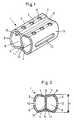
- the intervertebral implant shown in FIGS. 1 and 2consists essentially of a hollow body profile 1 in the form of a hollow cylinder, the outer surface 2 of which consists of a flattened, upper bone contact surface 3, a flattened, lower bone contact surface 4 and two side surfaces 5.
- the implantcan be made from a suitable metal (eg titanium), but in particular also from a body-compatible plastic, such as polyethylene.
- the upper and lower bone contact surfaces 3 and 4can be elastically compressed against the interior 6 of the hollow body profile 1, such that the maximum distance H between the upper and lower bone contact surfaces 3 and 4 can be reduced, typically by 2 mm. This allows an easier insertion of the implant into the intervertebral space.
- the side surfaces 5are provided with slot recesses 12, which can also be omitted when using a plastic material.
- the upper bone contact surface 3 and / or lower bone contact surface 4is provided with perforations 8 and a central groove 9.
- a snap-in lip 10is provided, which can be snapped into a lock 11.
- the hollow body profile 1 shown in FIG. 1is gripped by means of a suitable compression tool, so that a compressive force - typically of 12 Newtons - can be exerted on the upper and lower bone contact surfaces 3 and 4, which compresses the hollow body profile 1.
- a compressive force - typically of 12 Newtons -can be exerted on the upper and lower bone contact surfaces 3 and 4, which compresses the hollow body profile 1.
- the implantis now inserted into the cleared intervertebral space without any distraction instruments, the three-dimensional structuring 7, in the form of longitudinal grooves, making it easier to guide the implant and providing security against any slipping of the implant.
- the compression toolis removed and the latching lip 10 is erected and locked in the lock 11, so that the hollow body profile 1 can no longer be compressed.
- the implantcan now be filled with bone chips or bone substitute material.
Landscapes
- Health & Medical Sciences (AREA)
- Engineering & Computer Science (AREA)
- Biomedical Technology (AREA)
- Orthopedic Medicine & Surgery (AREA)
- Neurology (AREA)
- Heart & Thoracic Surgery (AREA)
- Oral & Maxillofacial Surgery (AREA)
- Transplantation (AREA)
- Cardiology (AREA)
- Vascular Medicine (AREA)
- Life Sciences & Earth Sciences (AREA)
- Animal Behavior & Ethology (AREA)
- General Health & Medical Sciences (AREA)
- Public Health (AREA)
- Veterinary Medicine (AREA)
- Prostheses (AREA)
Abstract
Description
Translated fromGermanDie Erfindung betrifft ein Zwischenwirbel-Implantat gemäss demOberbegriff des Patentanspruchs 1.
Solche Zwischenwirbel-Implantate werden bei der Fusion vonWirbelkörpern eingesetzt, insbesondere im Bereich der lumbalenWirbelsäule. Pro Zwischenwirbelraum werden ein bis zweiImplantate verwendet.
Aus dem Stand der Technik sind bereits verschiedene Typenderartiger Zwischenwirbel-Implantate bekannt, welche allerdingsfolgende Nachteile aufweisen:
- um das Implantat in den Zwischenwirbelbereich einführen zukönnen müssen die betroffenen Wirbel mit geeignetenInstrumenten distrahiert werden; und
- es besteht die Gefahr des Einsinkens des Implantats in dieEndplatten der betroffenen Wirbel.
Dieses bekannte Implantat weist folgende Nachteile auf:
- Zweiteiligkeit statt Einteiligkeit;
- nach erfolgtem Zusammenbau der beiden Teile ist kein Platzmehr im Inneren vorhanden um Knochenersatzmaterialaufzunehmen;
- nach erfolgtem Zusammenbau der beiden Teile ist das Implantatzwingenderweise unelastisch.
Such intervertebral implants are used in the fusion of vertebral bodies, especially in the area of the lumbar spine. One to two implants are used per intervertebral space.
Various types of such intervertebral implants are already known from the prior art, but they have the following disadvantages:
- In order to be able to insert the implant into the intervertebral area, the affected vertebrae must be distracted with suitable instruments; and
- there is a risk of the implant sinking into the end plates of the affected vertebrae.
This known implant has the following disadvantages:
- Two-part instead of one-part;
- after the two parts have been assembled, there is no more space inside to accommodate bone substitute material;
- after the two parts have been assembled, the implant is necessarily inelastic.
Hier will die Erfindung Abhilfe schaffen. Der Erfindung liegtdie Aufgabe zugrunde, ein Zwischenwirbel-Implantat zu schaffen,welches möglichst ohne Distraktionsinstrument in kontrollierbarerWeise in den ausgeräumten Zwischenwirbelraum einführbarist.The invention seeks to remedy this. The invention liesbased on the task of creating an intervertebral implant,which, if possible, can be controlled without a distraction instrumentCan be inserted into the cleared intervertebral spaceis.
Zur Lösung dieses Problems ist die eingangs genannte Anordnungdurch die Merkmale des kennzeichnenden Teils des unabhängigenAnspruchs 1 weitergebildet.The arrangement mentioned at the outset is to solve this problemby the characteristics of the characteristic part of the
Das abgeflachte Hohlkörperprofil kann die Form eines Hohlzylinders,hohlen Kegelstumpfs, hohlen Pyramidenstumpfs oderhohlen Keilstumpfes besitzen.The flattened hollow body profile can take the form of a hollow cylinder,hollow truncated cones, hollow truncated pyramids orhave hollow wedge stumps.
Dimensionen, Geometrie und Werkstoff sollen so gewählt werden,dass der maximale Abstand H zwischen oberer und untererKnochenkontaktfläche um 0,5 - 5,0 mm , vorzugsweise um 1 - 3 mmreduzierbar ist.
Bei Anwendung einer Druckkraft von 12 Newton auf die obere unduntere Knochenkontaktfläche sollte der maximale Abstand H um15 % bis 30 %, vorzugsweise um 20 % bis 25 % reduzierbar sein.
Die Komprimierbarkeit des Implantates gestattet dessen Einführungohne ein Distraktionsinstrument anwenden zu müssen.Dimensions, geometry and material should be chosen so that the maximum distance H between the upper and lower bone contact surface can be reduced by 0.5 - 5.0 mm, preferably by 1 - 3 mm.
When a pressure of 12 Newtons is applied to the upper and lower bone contact surface, the maximum distance H should be able to be reduced by 15% to 30%, preferably by 20% to 25%.
The compressibility of the implant allows it to be inserted without having to use a distraction device.
Damit ist der Vorteil erzielbar, dass ein minimalerKraftaufwand für die Implantation nötig ist und einkontrolliertes Einfügen des komprimierten Implantates möglichist. Eine minimalinvasive und offene Operationstechnik istdamit anwendbar.The advantage that a minimalForce is required for the implantation and onecontrolled insertion of the compressed implant possibleis. A minimally invasive and open surgical technique istherefore applicable.
Die grossen Auflageflächen des Implantates verhindern dessenEinsinken in die Endplatten.The large contact surfaces of the implant prevent thisSink into the end plates.
Eine bevorzugte Weiterbildung der Erfindung besteht darin, dassim Innenraum des Hohlkörperprofils eine Einrastlippe vorgesehenist, welche in eine Sperre einrastbar ist. Bei eingerasteterEinrastlippe ist die Komprimierbarkeit des Hohlkörperprofilswieder aufgehoben, so dass ein übliches rigidesImplantat resultiert.
Knochenspäne oder Knochenersatzmaterialien können leicht in dasvorne und hinten offene Hohlkörperprofil eingefüllt werden unddas Implantat mit wenigen Handgriffen sicher montiert werden.A preferred development of the invention consists in that a snap-in lip is provided in the interior of the hollow body profile, which can be snapped into a lock. When the snap-in lip is engaged, the compressibility of the hollow body profile is eliminated, so that a customary rigid implant results.
Bone chips or bone substitute materials can be easily filled into the hollow body profile, which is open at the front and back, and the implant can be securely mounted in just a few simple steps.
Um ein rasches Einwachsen des Knochens zu fördern, ist dasImplantat zweckmässigerweise mit Perforationen, vorzugsweisein Form von Längsausnehmungen versehen. Die Längsausnehmungenerlauben eine Kontrolle des Knocheneinwachsens mittelsRöntgenaufnahmen bei Verwendung eines röntgenstrahlenundurchlässigenMaterials.This is to promote rapid bone ingrowthConveniently implant with perforations, preferablyprovided in the form of longitudinal recesses. The longitudinal recessesallow control of bone ingrowth withX-rays when using an X-ray opaqueMaterials.
Zur Erhöhung der Lagestabilität des Implantates ist die obereund/oder untere Knochenkontaktfläche mit einer dreidimensionalenStrukturierung, vorzugsweise in Form vonLängsrillen versehen.The upper one is to increase the positional stability of the implantand / or lower bone contact surface with a three-dimensionalStructuring, preferably in the form ofProvide longitudinal grooves.
Folgende weitere Vorteile des erfindungsgemässen Implantatsergeben sich gegenüber dem Stand der Technik:
- Verrutschsicherheit;
- verbesserte Röntgendurchlässigkeit; und
- erhöhte Elastizität des Implantats.
- Slip resistance;
- improved radiopacity; and
- increased elasticity of the implant.
Die Erfindung und Weiterbildungen der Erfindung werden imfolgenden anhand der teilweise schematischen Darstellungeneines Ausführungsbeispiels noch näher erläutert.The invention and developments of the invention are infollowing based on the partially schematic representationsof an embodiment explained in more detail.
Es zeigen:
Das in den Fig. 1 und 2 dargestellte Zwischenwirbel-Implantatbesteht im wesentlichen aus einem Hohlkörperprofil 1 in Formeines Hohlzylinders, dessen Mantelfläche 2 aus einer abgeflachten,oberen Knochenkontaktfläche 3, einer abgeflachten,unteren Knochenkontaktfläche 4 und zwei Seitenflächen 5besteht.
Das Implantat kann aus einem geeigneten Metall (z.B. Titan),insbesondere aber auch aus einem körperverträglichen Kunststoff,wie Polyethylen gefertigt werden.
Die obere und untere Knochenkontaktfläche 3 und 4 ist gegen denInnenraum 6 des Hohlkörperprofils 1 elastisch komprimierbar,derart dass der maximale Abstand H zwischen oberer und untererKnochenkontaktfläche 3 und 4 reduzierbar ist, typischerweise um2 mm. Dies erlaubt eine einfachere Einführung des Implantats inden Zwischenwirbelraum.The intervertebral implant shown in FIGS. 1 and 2 consists essentially of a
The implant can be made from a suitable metal (eg titanium), but in particular also from a body-compatible plastic, such as polyethylene.
The upper and lower
Die Seitenflächen 5 sind mit Langlochausnehmungen 12 versehen,welche bei Verwendung eines Kunststoffmaterials auch weggelassenwerden können. Die obere Knochenkontaktfläche 3 und/oderuntere Knochenkontaktfläche 4 ist mit Perforationen 8 sowieeiner Mittelrille 9 versehen.
Im Innenraum 6 des Hohlkörperprofils 1 ist eine Einrastlippe 10vorgesehen, welche in eine Sperre 11 einrastbar ist.The
In the
Nachstehend wird nun die klinische Anwendung im Detail beschrieben.Das in Fig. 1 gezeigte Hohlkörperprofil 1 wirdmittels eines geeigneten Kompressionswerkzeugs gefasst, so dass auf die obere und untere Knochenkontaktfläche 3 und 4 eineDruckkraft - typischerweise von 12 Newton - ausgeübt werdenkann, welche das Hohlkörperprofil 1 komprimiert. In diesemZustand wird das Implantat nun möglichst ohne Distraktionsinstrumentein den ausgeräumten Zwischenwirbelraum eingeführt,wobei die dreidimensionalen Strukturierungen 7, in Form vonLängsrillen die Führung des Implantats erleichtern und eineSicherung gegen ein allfälliges Verrutschen des Implantatsbieten.
Das Kompressionswerkzeug wird entfernt und die Einrastlippe 10aufgerichtet und in die Sperre 11 eingerastet, so dass dasHohlkörperprofil 1 nun nicht mehr komprimierbar ist. DasImplantat kann nun mit Knochenspänen oder Knochenersatzmaterialgefüllt werden.The clinical application will now be described in detail below. The
The compression tool is removed and the
Claims (13)
- Intervertebral implant comprising a flattened shaped hollow element (1), having anouter surface (2) that includes a flattened upper bone-contact face (3), a flattened lowerbone-contact face (4) and a lateral face (5), whereby the upper and lower bone-contactfaces (3;4) are elastically compressible towards the interior space (6) of the hollowelement (1),
characterized in thata) the hollow element (1) is shaped as a hollow cylinder, hollow truncated cone, hollowtruncated pyramid or hollow truncated wedge;b) the outer surface (2) of the hollow element (1) includes a second lateral face (5); andc) upon application of a force of pressure the upper and lower bone-contact faces (3;4)are compressible towards each other such that the maximum distance H between theupper and lower bone-contact faces (3;4) is reducible between 0,5 - 5,0 mm. - Implant according to claim 1,characterized in that the maximum distance H betweenthe upper and lower bone-contact faces (3;4) is reducible between 1 - 3 mm.
- Implant according to claim 1 or 2,characterized in that the maximum distance H isreducible by 30% to 40% upon application of a force of pressure of 12 Newton onto theupper and lower bone-contact faces (3;4).
- Implant according to claim 3,characterized in that the maximum distance H isreducible by 20% to 25% upon application of a force of pressure of 12 Newton onto theupper and lower bone-contact faces (3;4).
- Implant according to one of the claims 1 to 4,characterized in that within the interiorspace (6) of the hollow element (1) an engagement lip (10) is provided, which is engageable within a interlock means (11) such that compression of the hollow element(1) is prevented.
- Implant according to one of the claims 1 - 5,characterized in that the lateral faces (5)are provided with elongated apertures.
- Implant according to one of the claims 1 - 6,characterized in that the upper bone-contactface (3) and/or the lower bone-contact face (4) are provided with a three-dimensionalstructure (7).
- Implant according to claim 7,characterized in that the three-dimensional structure (7)is realised by means of longitudinal grooves.
- Implant according to one of the claims 1 - 8,characterized in that the upper bone-contactface (3) and/or the lower bone-contact face (4) are provided with perforations(8).
- Implant according to one of the claims 1 - 9,characterized in that the upper bone-contactface (3) and/or the lower bone-contact face (4) are provided with one or aplurality of central grooves (9).
- Implant according to one of the claims 1 - 10,characterized in that it is made of abiocompatible plastic material.
- Implant according to claim 11,characterized in that the biocompatible plasticmaterial is polyethylene.
- Implant according to one of the claims 1 - 12,characterized in that it is coated withhydroxylapatite or tricalciumphosphate (TCP).
Applications Claiming Priority (1)
| Application Number | Priority Date | Filing Date | Title |
|---|---|---|---|
| PCT/CH1995/000244WO1997015247A1 (en) | 1995-10-20 | 1995-10-20 | Intervertebral implant with compressible shaped hollow element |
Publications (2)
| Publication Number | Publication Date |
|---|---|
| EP0857042A1 EP0857042A1 (en) | 1998-08-12 |
| EP0857042B1true EP0857042B1 (en) | 2001-11-07 |
Family
ID=4549982
Family Applications (1)
| Application Number | Title | Priority Date | Filing Date |
|---|---|---|---|
| EP95934031AExpired - LifetimeEP0857042B1 (en) | 1995-10-20 | 1995-10-20 | Intervertebral implant with compressible shaped hollow element |
Country Status (9)
| Country | Link |
|---|---|
| US (1) | US6143031A (en) |
| EP (1) | EP0857042B1 (en) |
| JP (1) | JPH11513598A (en) |
| KR (1) | KR100392091B1 (en) |
| AT (1) | ATE208171T1 (en) |
| CA (1) | CA2229714C (en) |
| DE (1) | DE59509814D1 (en) |
| TW (1) | TW360529B (en) |
| WO (1) | WO1997015247A1 (en) |
Cited By (24)
| Publication number | Priority date | Publication date | Assignee | Title |
|---|---|---|---|---|
| US7678148B2 (en) | 2004-07-23 | 2010-03-16 | Warsaw Orthopedic, Inc. | Expandable spinal implant having interlocking geometry for structural support |
| US10856997B2 (en) | 2018-02-22 | 2020-12-08 | Warsaw Orthopedic, Inc. | Expandable spinal implant system and method of using same |
| US11020239B2 (en) | 2018-02-22 | 2021-06-01 | Warsaw Orthopedic, Inc. | Expandable spinal implant system and method of using same |
| US11285014B1 (en) | 2020-11-05 | 2022-03-29 | Warsaw Orthopedic, Inc. | Expandable inter-body device, system, and method |
| US11291554B1 (en) | 2021-05-03 | 2022-04-05 | Medtronic, Inc. | Unibody dual expanding interbody implant |
| US11376134B1 (en) | 2020-11-05 | 2022-07-05 | Warsaw Orthopedic, Inc. | Dual expanding spinal implant, system, and method of use |
| US11395743B1 (en) | 2021-05-04 | 2022-07-26 | Warsaw Orthopedic, Inc. | Externally driven expandable interbody and related methods |
| US11517443B2 (en) | 2020-11-05 | 2022-12-06 | Warsaw Orthopedic, Inc. | Dual wedge expandable implant, system and method of use |
| US11564724B2 (en) | 2020-11-05 | 2023-01-31 | Warsaw Orthopedic, Inc. | Expandable inter-body device, system and method |
| US11612499B2 (en) | 2021-06-24 | 2023-03-28 | Warsaw Orthopedic, Inc. | Expandable interbody implant |
| US11638653B2 (en) | 2020-11-05 | 2023-05-02 | Warsaw Orthopedic, Inc. | Surgery instruments with a movable handle |
| US11730608B2 (en) | 2021-07-13 | 2023-08-22 | Warsaw Orthopedic, Inc. | Monoblock expandable interbody implant |
| US11833059B2 (en) | 2020-11-05 | 2023-12-05 | Warsaw Orthopedic, Inc. | Expandable inter-body device, expandable plate system, and associated methods |
| US11850163B2 (en) | 2022-02-01 | 2023-12-26 | Warsaw Orthopedic, Inc. | Interbody implant with adjusting shims |
| US11963881B2 (en) | 2020-11-05 | 2024-04-23 | Warsaw Orthopedic, Inc. | Expandable inter-body device, system, and method |
| US12036132B2 (en) | 2018-02-22 | 2024-07-16 | Warsaw Orthopedic, Inc. | Expandable spinal implant system and method of using same |
| US12121453B2 (en) | 2020-11-05 | 2024-10-22 | Warsaw Orthopedic, Inc. | Dual wedge expandable implant with eyelets, system, and method of use |
| US12171439B2 (en) | 2020-11-05 | 2024-12-24 | Warsaw Orthopedic, Inc. | Protected drill |
| US12239544B2 (en) | 2020-11-05 | 2025-03-04 | Warsaw Orthopedic, Inc. | Rhomboid shaped implants |
| US12268614B2 (en) | 2021-06-24 | 2025-04-08 | Warsaw Orthopedic, Inc. | Interbody implant with adjusting shims |
| US12295865B2 (en) | 2021-06-24 | 2025-05-13 | Warsaw Orthopedic, Inc. | Expandable interbody implant and corresponding inserter |
| US12318308B2 (en) | 2020-11-05 | 2025-06-03 | Warsaw Orthopedic, Inc. | Dual expandable inter-body device |
| US12414863B2 (en) | 2021-06-24 | 2025-09-16 | Warsaw Orthopedic, Inc. | Expandable interbody implant and corresponding surgical tool |
| US12440349B2 (en) | 2022-02-04 | 2025-10-14 | Warsaw Orthopedic, Inc. | Expandable interbody implant and breakoff screw |
Families Citing this family (101)
| Publication number | Priority date | Publication date | Assignee | Title |
|---|---|---|---|---|
| US5749916A (en)* | 1997-01-21 | 1998-05-12 | Spinal Innovations | Fusion implant |
| AU744371B2 (en)* | 1997-04-25 | 2002-02-21 | Stryker European Holdings I, Llc | Two-part intersomatic implant |
| DE29720022U1 (en)* | 1997-11-12 | 1998-01-15 | SCHÄFER micomed GmbH, 73035 Göppingen | Intervertebral implant |
| US20010001129A1 (en) | 1997-12-10 | 2001-05-10 | Mckay William F. | Osteogenic fusion device |
| AU775275B2 (en)* | 1997-12-19 | 2004-07-29 | Warsaw Orthopedic, Inc. | Partial disc prosthesis |
| FR2772594B1 (en)* | 1997-12-19 | 2000-05-05 | Henry Graf | REAR PARTIAL DISCAL PROSTHESIS |
| US6224631B1 (en) | 1998-03-20 | 2001-05-01 | Sulzer Spine-Tech Inc. | Intervertebral implant with reduced contact area and method |
| US6835208B2 (en)* | 1998-03-30 | 2004-12-28 | J. Alexander Marchosky | Prosthetic system |
| WO1999049818A1 (en)* | 1998-03-30 | 1999-10-07 | Marchosky J Alexander | Prosthetic system |
| EP1123069B1 (en) | 1998-10-20 | 2008-02-06 | Synthes GmbH | Strain regulating fusion cage for spinal fusion surgery |
| US6193757B1 (en) | 1998-10-29 | 2001-02-27 | Sdgi Holdings, Inc. | Expandable intervertebral spacers |
| FR2790945B1 (en)* | 1999-03-19 | 2001-08-03 | Von Bunau Frederic Hansen | INTERSOMATIC VERTEBRAL IMPLANT |
| FR2897259B1 (en) | 2006-02-15 | 2008-05-09 | Ldr Medical Soc Par Actions Si | INTERSOMATIC TRANSFORAMINAL CAGE WITH INTERBREBAL FUSION GRAFT AND CAGE IMPLANTATION INSTRUMENT |
| ES2270888T3 (en) | 1999-12-01 | 2007-04-16 | Henry Graf | INTERVERTEBRAL STABILIZATION DEVICE. |
| FR2801783B1 (en)* | 1999-12-02 | 2002-06-14 | Claude Laville | INTERSOMATIC CAGE |
| EP1645248B8 (en) | 2000-02-04 | 2010-06-16 | Warsaw Orthopedic, Inc. | Expandable interbody spinal fusion implant having pivotally attached blocker |
| US6500205B1 (en) | 2000-04-19 | 2002-12-31 | Gary K. Michelson | Expandable threaded arcuate interbody spinal fusion implant with cylindrical configuration during insertion |
| US6814756B1 (en) | 2000-02-04 | 2004-11-09 | Gary K. Michelson | Expandable threaded arcuate interbody spinal fusion implant with lordotic configuration during insertion |
| USD493225S1 (en) | 2000-06-12 | 2004-07-20 | Ortho Development Corporation | Implant |
| US6579318B2 (en) | 2000-06-12 | 2003-06-17 | Ortho Development Corporation | Intervertebral spacer |
| US6808537B2 (en)* | 2000-07-07 | 2004-10-26 | Gary Karlin Michelson | Expandable implant with interlocking walls |
| EP1328217A2 (en)* | 2000-09-19 | 2003-07-23 | SDGI Holdings, Inc. | Osteogenic fusion devices |
| DE60224850T2 (en) | 2001-02-04 | 2009-01-22 | Warsaw Orthopedic, Inc., Warsaw | Instrumentation for introducing and positioning an expandable intervertebral fusion implant |
| US6595998B2 (en)* | 2001-03-08 | 2003-07-22 | Spinewave, Inc. | Tissue distraction device |
| US6635087B2 (en) | 2001-08-29 | 2003-10-21 | Christopher M. Angelucci | Laminoplasty implants and methods of use |
| US7267687B2 (en)* | 2001-10-02 | 2007-09-11 | Rex Medical, L.P | Spinal implant and method of use |
| FR2833609B1 (en)* | 2001-12-19 | 2004-12-03 | Natural Implant | ACTIVE PHASE CELL OR TISSUE SAMPLING DEVICE AND USES |
| US7001433B2 (en) | 2002-05-23 | 2006-02-21 | Pioneer Laboratories, Inc. | Artificial intervertebral disc device |
| US8388684B2 (en) | 2002-05-23 | 2013-03-05 | Pioneer Signal Technology, Inc. | Artificial disc device |
| EP1542626B1 (en) | 2002-08-15 | 2012-09-26 | Synthes GmbH | Controlled artificial intervertebral disc implant |
| CA2495404C (en) | 2002-08-15 | 2011-05-03 | Justin K. Coppes | Intervertebral disc implant |
| US6712852B1 (en)* | 2002-09-30 | 2004-03-30 | Depuy Spine, Inc. | Laminoplasty cage |
| US7569074B2 (en)* | 2003-12-11 | 2009-08-04 | Warsaw Orthopedic, Inc. | Expandable intervertebral implant |
| CN1310626C (en)* | 2003-12-15 | 2007-04-18 | 林君甫 | Support body placed between two vertebral bodies |
| US7507241B2 (en)* | 2004-04-05 | 2009-03-24 | Expanding Orthopedics Inc. | Expandable bone device |
| US8425570B2 (en) | 2004-08-09 | 2013-04-23 | Si-Bone Inc. | Apparatus, systems, and methods for achieving anterior lumbar interbody fusion |
| US9949843B2 (en) | 2004-08-09 | 2018-04-24 | Si-Bone Inc. | Apparatus, systems, and methods for the fixation or fusion of bone |
| US20180228621A1 (en) | 2004-08-09 | 2018-08-16 | Mark A. Reiley | Apparatus, systems, and methods for the fixation or fusion of bone |
| US8388667B2 (en) | 2004-08-09 | 2013-03-05 | Si-Bone, Inc. | Systems and methods for the fixation or fusion of bone using compressive implants |
| US20070156241A1 (en) | 2004-08-09 | 2007-07-05 | Reiley Mark A | Systems and methods for the fixation or fusion of bone |
| US8444693B2 (en) | 2004-08-09 | 2013-05-21 | Si-Bone Inc. | Apparatus, systems, and methods for achieving lumbar facet fusion |
| US8414648B2 (en) | 2004-08-09 | 2013-04-09 | Si-Bone Inc. | Apparatus, systems, and methods for achieving trans-iliac lumbar fusion |
| US8470004B2 (en) | 2004-08-09 | 2013-06-25 | Si-Bone Inc. | Apparatus, systems, and methods for stabilizing a spondylolisthesis |
| US9662158B2 (en) | 2004-08-09 | 2017-05-30 | Si-Bone Inc. | Systems and methods for the fixation or fusion of bone at or near a sacroiliac joint |
| US20060036251A1 (en) | 2004-08-09 | 2006-02-16 | Reiley Mark A | Systems and methods for the fixation or fusion of bone |
| US20060167547A1 (en)* | 2005-01-21 | 2006-07-27 | Loubert Suddaby | Expandable intervertebral fusion implants having hinged sidewalls |
| US8066742B2 (en) | 2005-03-31 | 2011-11-29 | Warsaw Orthopedic, Inc. | Intervertebral prosthetic device for spinal stabilization and method of implanting same |
| KR100655170B1 (en) | 2005-04-07 | 2006-12-08 | 한국과학기술원 | Artificial joint device used in the thigh |
| DE602006020043D1 (en)* | 2005-04-29 | 2011-03-24 | Warsaw Orthopedic Inc | EXPANDABLE RIBBON IMPLANT |
| US20070005064A1 (en)* | 2005-06-27 | 2007-01-04 | Sdgi Holdings | Intervertebral prosthetic device for spinal stabilization and method of implanting same |
| US8357181B2 (en) | 2005-10-27 | 2013-01-22 | Warsaw Orthopedic, Inc. | Intervertebral prosthetic device for spinal stabilization and method of implanting same |
| US7862591B2 (en) | 2005-11-10 | 2011-01-04 | Warsaw Orthopedic, Inc. | Intervertebral prosthetic device for spinal stabilization and method of implanting same |
| WO2007075411A2 (en)* | 2005-12-16 | 2007-07-05 | Thomas Haider Patents, A Limited Liability Company | An intervertebral prosthesis for supporting adjacent vertebral bodies enabling the creation of soft fusion and method |
| US8287914B2 (en)* | 2006-01-12 | 2012-10-16 | Rutgers, The State University Of New Jersey | Biomimetic hydroxyapatite synthesis |
| US8083795B2 (en) | 2006-01-18 | 2011-12-27 | Warsaw Orthopedic, Inc. | Intervertebral prosthetic device for spinal stabilization and method of manufacturing same |
| US8262698B2 (en) | 2006-03-16 | 2012-09-11 | Warsaw Orthopedic, Inc. | Expandable device for insertion between anatomical structures and a procedure utilizing same |
| US8016837B2 (en) | 2006-04-06 | 2011-09-13 | Synthes Usa, Llc | Remotely adjustable tissue displacement device |
| US8118844B2 (en) | 2006-04-24 | 2012-02-21 | Warsaw Orthopedic, Inc. | Expandable device for insertion between anatomical structures and a procedure utilizing same |
| US20070270874A1 (en)* | 2006-04-24 | 2007-11-22 | Sdgi Holdings, Inc. | Surgical distraction device and procedure |
| US8062337B2 (en) | 2006-05-04 | 2011-11-22 | Warsaw Orthopedic, Inc. | Expandable device for insertion between anatomical structures and a procedure utilizing same |
| US8048119B2 (en) | 2006-07-20 | 2011-11-01 | Warsaw Orthopedic, Inc. | Apparatus for insertion between anatomical structures and a procedure utilizing same |
| WO2008034135A2 (en) | 2006-09-15 | 2008-03-20 | Pioneer Surgical Technology, Inc. | Joint arthroplasty devices having articulating members |
| US8715350B2 (en) | 2006-09-15 | 2014-05-06 | Pioneer Surgical Technology, Inc. | Systems and methods for securing an implant in intervertebral space |
| US8092533B2 (en)* | 2006-10-03 | 2012-01-10 | Warsaw Orthopedic, Inc. | Dynamic devices and methods for stabilizing vertebral members |
| US20080161920A1 (en)* | 2006-10-03 | 2008-07-03 | Warsaw Orthopedic, Inc. | Dynamizing Interbody Implant and Methods for Stabilizing Vertebral Members |
| CA2668655A1 (en) | 2006-11-16 | 2008-05-29 | Rex Medical, L.P. | Spinal implant and method of use |
| US20080167686A1 (en)* | 2007-01-05 | 2008-07-10 | Warsaw Orthopedic, Inc. | Non-Rigid Intervertebral Spacers |
| BRPI0808018A2 (en)* | 2007-03-07 | 2014-06-17 | Ulrich Gmbh & Co Kg | INTERVERTEBRAL IMPLANT WITH AN ELASTIC COMPONENT |
| FR2914843B1 (en)* | 2007-04-13 | 2010-04-23 | Creaspine | INTERVERTEBRAL IMPLANT FOR THE HUMAN OR ANIMAL BODY |
| US20090180931A1 (en) | 2007-09-17 | 2009-07-16 | Sequenom, Inc. | Integrated robotic sample transfer device |
| US20110029087A1 (en)* | 2008-04-04 | 2011-02-03 | Haider Thomas T | Intervertebral prostheses with compliant filler material for supporting adjacent vertebral bodies and method |
| US8216316B2 (en)* | 2008-12-17 | 2012-07-10 | X-Spine Systems, Inc. | Prosthetic implant with biplanar angulation and compound angles |
| EP2547292B1 (en) | 2010-03-16 | 2019-04-24 | Pinnacle Spine Group, LLC | Ntervertebral implants and graft delivery systems |
| EP3017793A3 (en)* | 2010-07-15 | 2016-08-17 | Spine Wave, Inc. | A plastically deformable inter-osseous device |
| US9380932B1 (en) | 2011-11-02 | 2016-07-05 | Pinnacle Spine Group, Llc | Retractor devices for minimally invasive access to the spine |
| EP2606860B1 (en)* | 2011-12-22 | 2016-07-20 | Biedermann Technologies GmbH & Co. KG | Expandable intervertebral implant |
| US9198769B2 (en) | 2011-12-23 | 2015-12-01 | Pioneer Surgical Technology, Inc. | Bone anchor assembly, bone plate system, and method |
| US9044321B2 (en) | 2012-03-09 | 2015-06-02 | Si-Bone Inc. | Integrated implant |
| US10363140B2 (en) | 2012-03-09 | 2019-07-30 | Si-Bone Inc. | Systems, device, and methods for joint fusion |
| US8778026B2 (en) | 2012-03-09 | 2014-07-15 | Si-Bone Inc. | Artificial SI joint |
| EP3818947B1 (en) | 2012-05-04 | 2023-08-30 | SI-Bone, Inc. | Fenestrated implant |
| EP2716261A1 (en)* | 2012-10-02 | 2014-04-09 | Titan Spine, LLC | Implants with self-deploying anchors |
| US10327910B2 (en) | 2013-03-14 | 2019-06-25 | X-Spine Systems, Inc. | Spinal implant and assembly |
| WO2014159739A1 (en) | 2013-03-14 | 2014-10-02 | Pinnacle Spine Group, Llc | Interbody implants and graft delivery systems |
| WO2014145902A1 (en) | 2013-03-15 | 2014-09-18 | Si-Bone Inc. | Implants for spinal fixation or fusion |
| US11147688B2 (en) | 2013-10-15 | 2021-10-19 | Si-Bone Inc. | Implant placement |
| US9839448B2 (en) | 2013-10-15 | 2017-12-12 | Si-Bone Inc. | Implant placement |
| JP6542362B2 (en) | 2014-09-18 | 2019-07-10 | エスアイ−ボーン・インコーポレイテッドSi−Bone, Inc. | Matrix implant |
| US10166033B2 (en) | 2014-09-18 | 2019-01-01 | Si-Bone Inc. | Implants for bone fixation or fusion |
| US10376206B2 (en) | 2015-04-01 | 2019-08-13 | Si-Bone Inc. | Neuromonitoring systems and methods for bone fixation or fusion procedures |
| WO2019051260A1 (en) | 2017-09-08 | 2019-03-14 | Pioneer Surgical Technology, Inc. | Intervertebral implants, instruments, and methods |
| US11116519B2 (en) | 2017-09-26 | 2021-09-14 | Si-Bone Inc. | Systems and methods for decorticating the sacroiliac joint |
| USD907771S1 (en) | 2017-10-09 | 2021-01-12 | Pioneer Surgical Technology, Inc. | Intervertebral implant |
| ES3011907T3 (en) | 2018-03-28 | 2025-04-08 | Si Bone Inc | Threaded implants for use across bone segments |
| EP4613244A2 (en) | 2019-02-14 | 2025-09-10 | SI-Bone Inc. | Implants for spinal fixation and or fusion |
| US11369419B2 (en) | 2019-02-14 | 2022-06-28 | Si-Bone Inc. | Implants for spinal fixation and or fusion |
| JP7646654B2 (en) | 2019-11-21 | 2025-03-17 | エスアイ-ボーン・インコーポレイテッド | Rod coupling assembly for bone stabilization construct - Patent application |
| AU2020392121B2 (en) | 2019-11-27 | 2025-05-22 | Si-Bone, Inc. | Bone stabilizing implants and methods of placement across SI joints |
| EP4072452A4 (en) | 2019-12-09 | 2023-12-20 | SI-Bone, Inc. | Sacro-iliac joint stabilizing implants and methods of implantation |
| EP4259015A4 (en) | 2020-12-09 | 2024-09-11 | SI-Bone, Inc. | SACROILIAC JOINT STABILIZATION IMPLANTS AND METHODS OF IMPLANTATION |
| WO2025038769A1 (en) | 2023-08-15 | 2025-02-20 | Si-Bone Inc. | Pelvic stabilization implants, methods of use and manufacture |
Family Cites Families (11)
| Publication number | Priority date | Publication date | Assignee | Title |
|---|---|---|---|---|
| GB8620937D0 (en)* | 1986-08-29 | 1986-10-08 | Shepperd J A N | Spinal implant |
| US4863477A (en)* | 1987-05-12 | 1989-09-05 | Monson Gary L | Synthetic intervertebral disc prosthesis |
| DE4012622C1 (en)* | 1990-04-20 | 1991-07-18 | Eska Medical Luebeck Medizintechnik Gmbh & Co, 2400 Luebeck, De | Two-part metal vertebra implant - has parts locked by two toothed racks, pre-stressed by elastic cushion between both implant parts |
| US5123926A (en)* | 1991-02-22 | 1992-06-23 | Madhavan Pisharodi | Artificial spinal prosthesis |
| US5171278A (en)* | 1991-02-22 | 1992-12-15 | Madhavan Pisharodi | Middle expandable intervertebral disk implants |
| US5458642A (en)* | 1994-01-18 | 1995-10-17 | Beer; John C. | Synthetic intervertebral disc |
| FR2715293B1 (en)* | 1994-01-26 | 1996-03-22 | Biomat | Vertebral interbody fusion cage. |
| DE4409392A1 (en)* | 1994-03-18 | 1995-09-21 | Biedermann Motech Gmbh | Adjustable vertebral body |
| FR2728159B1 (en)* | 1994-12-16 | 1997-06-27 | Tornier Sa | ELASTIC DISC PROSTHESIS |
| CN1134810A (en)* | 1995-02-17 | 1996-11-06 | 索发默达纳集团股份有限公司 | Improved interbody spinal fusion implants |
| US5782919A (en)* | 1995-03-27 | 1998-07-21 | Sdgi Holdings, Inc. | Interbody fusion device and method for restoration of normal spinal anatomy |
- 1995
- 1995-10-20USUS09/051,770patent/US6143031A/ennot_activeExpired - Lifetime
- 1995-10-20ATAT95934031Tpatent/ATE208171T1/ennot_activeIP Right Cessation
- 1995-10-20JPJP9516102Apatent/JPH11513598A/enactivePending
- 1995-10-20EPEP95934031Apatent/EP0857042B1/ennot_activeExpired - Lifetime
- 1995-10-20DEDE59509814Tpatent/DE59509814D1/ennot_activeExpired - Lifetime
- 1995-10-20KRKR10-1998-0702784Apatent/KR100392091B1/ennot_activeExpired - Fee Related
- 1995-10-20WOPCT/CH1995/000244patent/WO1997015247A1/enactiveIP Right Grant
- 1995-10-20CACA002229714Apatent/CA2229714C/ennot_activeExpired - Lifetime
- 1996
- 1996-10-02TWTW085111994Apatent/TW360529B/ennot_activeIP Right Cessation
Cited By (30)
| Publication number | Priority date | Publication date | Assignee | Title |
|---|---|---|---|---|
| US8303658B2 (en) | 2004-07-23 | 2012-11-06 | Warsaw Orthopedic, Inc. | Expandable spinal implant having interlocking geometry for structural support |
| US7678148B2 (en) | 2004-07-23 | 2010-03-16 | Warsaw Orthopedic, Inc. | Expandable spinal implant having interlocking geometry for structural support |
| US11752005B2 (en) | 2018-02-22 | 2023-09-12 | Warsaw Orthopedic, Inc. | Expandable spinal implant system and method of using same |
| US10856997B2 (en) | 2018-02-22 | 2020-12-08 | Warsaw Orthopedic, Inc. | Expandable spinal implant system and method of using same |
| US11020239B2 (en) | 2018-02-22 | 2021-06-01 | Warsaw Orthopedic, Inc. | Expandable spinal implant system and method of using same |
| US12036132B2 (en) | 2018-02-22 | 2024-07-16 | Warsaw Orthopedic, Inc. | Expandable spinal implant system and method of using same |
| US12121453B2 (en) | 2020-11-05 | 2024-10-22 | Warsaw Orthopedic, Inc. | Dual wedge expandable implant with eyelets, system, and method of use |
| US11963881B2 (en) | 2020-11-05 | 2024-04-23 | Warsaw Orthopedic, Inc. | Expandable inter-body device, system, and method |
| US11517443B2 (en) | 2020-11-05 | 2022-12-06 | Warsaw Orthopedic, Inc. | Dual wedge expandable implant, system and method of use |
| US11564724B2 (en) | 2020-11-05 | 2023-01-31 | Warsaw Orthopedic, Inc. | Expandable inter-body device, system and method |
| US12364529B2 (en) | 2020-11-05 | 2025-07-22 | Warsaw Orthopedic, Inc. | Expandable inter-body device, system, and method |
| US11617658B2 (en) | 2020-11-05 | 2023-04-04 | Warsaw Orthopedic, Inc. | Expandable inter-body device, system and method |
| US11638653B2 (en) | 2020-11-05 | 2023-05-02 | Warsaw Orthopedic, Inc. | Surgery instruments with a movable handle |
| US12318308B2 (en) | 2020-11-05 | 2025-06-03 | Warsaw Orthopedic, Inc. | Dual expandable inter-body device |
| US11376134B1 (en) | 2020-11-05 | 2022-07-05 | Warsaw Orthopedic, Inc. | Dual expanding spinal implant, system, and method of use |
| US11833059B2 (en) | 2020-11-05 | 2023-12-05 | Warsaw Orthopedic, Inc. | Expandable inter-body device, expandable plate system, and associated methods |
| US12239544B2 (en) | 2020-11-05 | 2025-03-04 | Warsaw Orthopedic, Inc. | Rhomboid shaped implants |
| US12171439B2 (en) | 2020-11-05 | 2024-12-24 | Warsaw Orthopedic, Inc. | Protected drill |
| US11969196B2 (en) | 2020-11-05 | 2024-04-30 | Warsaw Orthopedic, Inc. | Expandable inter-body device, system, and method |
| US11285014B1 (en) | 2020-11-05 | 2022-03-29 | Warsaw Orthopedic, Inc. | Expandable inter-body device, system, and method |
| US12053392B2 (en) | 2020-11-05 | 2024-08-06 | Warsaw Orthopedic, Inc. | Expandable inter-body device, expandable plate system, and associated methods |
| US11291554B1 (en) | 2021-05-03 | 2022-04-05 | Medtronic, Inc. | Unibody dual expanding interbody implant |
| US11395743B1 (en) | 2021-05-04 | 2022-07-26 | Warsaw Orthopedic, Inc. | Externally driven expandable interbody and related methods |
| US12268614B2 (en) | 2021-06-24 | 2025-04-08 | Warsaw Orthopedic, Inc. | Interbody implant with adjusting shims |
| US12295865B2 (en) | 2021-06-24 | 2025-05-13 | Warsaw Orthopedic, Inc. | Expandable interbody implant and corresponding inserter |
| US11612499B2 (en) | 2021-06-24 | 2023-03-28 | Warsaw Orthopedic, Inc. | Expandable interbody implant |
| US12414863B2 (en) | 2021-06-24 | 2025-09-16 | Warsaw Orthopedic, Inc. | Expandable interbody implant and corresponding surgical tool |
| US11730608B2 (en) | 2021-07-13 | 2023-08-22 | Warsaw Orthopedic, Inc. | Monoblock expandable interbody implant |
| US11850163B2 (en) | 2022-02-01 | 2023-12-26 | Warsaw Orthopedic, Inc. | Interbody implant with adjusting shims |
| US12440349B2 (en) | 2022-02-04 | 2025-10-14 | Warsaw Orthopedic, Inc. | Expandable interbody implant and breakoff screw |
Also Published As
| Publication number | Publication date |
|---|---|
| CA2229714C (en) | 2003-12-30 |
| WO1997015247A1 (en) | 1997-05-01 |
| EP0857042A1 (en) | 1998-08-12 |
| CA2229714A1 (en) | 1997-05-01 |
| DE59509814D1 (en) | 2001-12-13 |
| KR100392091B1 (en) | 2004-02-05 |
| KR19990064290A (en) | 1999-07-26 |
| US6143031A (en) | 2000-11-07 |
| ATE208171T1 (en) | 2001-11-15 |
| TW360529B (en) | 1999-06-11 |
| JPH11513598A (en) | 1999-11-24 |
Similar Documents
| Publication | Publication Date | Title |
|---|---|---|
| EP0857042B1 (en) | Intervertebral implant with compressible shaped hollow element | |
| EP0857043B1 (en) | Inter-vertebral implant | |
| DE60034893T2 (en) | ROLLING SPINE IMPLANT | |
| EP1648351B1 (en) | Intervertebral implant comprising temporary blocking means | |
| DE10135771B4 (en) | Facet joint implant | |
| DE69837883T2 (en) | Spinal implant and cutting tool preparation accessory for implant insertion | |
| DE19529605C2 (en) | Intervertebral implant | |
| DE60128391T2 (en) | DYNAMIC IMPLANT INTERMEDIATE SPARKLING | |
| DE60128689T2 (en) | EDDY CAGE IMPLANT | |
| DE69729140T2 (en) | Instrumentation for the implantation of a surgical implant | |
| DE69818246T2 (en) | FUSION DEVICE WITH MULTIVARIABLE HEIGHT | |
| DE69637271T2 (en) | Truncated conical spondylodesis implants | |
| DE102005004563B4 (en) | Spreadable implant for preferably dorsal arrangement between the vertebral bodies of the spine | |
| DE60133370T2 (en) | SPINE IMPLANT AND INTRODUCTION DEVICE | |
| DE4315757C1 (en) | Vertebral implant | |
| DE102010041959A1 (en) | Medical implant | |
| WO2001015637A1 (en) | Intervertebral implant | |
| WO2003075804A1 (en) | Cervical intervertebral prosthesis | |
| EP1415623A1 (en) | Implant for positioning between vertebral bodies of the spine | |
| DE60018988T2 (en) | CURVED CAGE FOR IMMOBILIZING THE SPINE | |
| DE102019000965A1 (en) | Bone anchoring device for pedicle access | |
| DE10061975C2 (en) | Intervertebral disc replacement implant part | |
| EP1624831A1 (en) | Device for implanting in a human or animal vertebral column | |
| DE2839092C3 (en) | One-piece thigh part of a hip joint endoprosthesis | |
| DE20315613U1 (en) | Intervertebral implant |
Legal Events
| Date | Code | Title | Description |
|---|---|---|---|
| PUAI | Public reference made under article 153(3) epc to a published international application that has entered the european phase | Free format text:ORIGINAL CODE: 0009012 | |
| 17P | Request for examination filed | Effective date:19971108 | |
| AK | Designated contracting states | Kind code of ref document:A1 Designated state(s):AT CH DE FR LI | |
| 17Q | First examination report despatched | Effective date:19990111 | |
| GRAG | Despatch of communication of intention to grant | Free format text:ORIGINAL CODE: EPIDOS AGRA | |
| GRAG | Despatch of communication of intention to grant | Free format text:ORIGINAL CODE: EPIDOS AGRA | |
| GRAH | Despatch of communication of intention to grant a patent | Free format text:ORIGINAL CODE: EPIDOS IGRA | |
| GRAH | Despatch of communication of intention to grant a patent | Free format text:ORIGINAL CODE: EPIDOS IGRA | |
| GRAA | (expected) grant | Free format text:ORIGINAL CODE: 0009210 | |
| AK | Designated contracting states | Kind code of ref document:B1 Designated state(s):AT CH DE FR LI | |
| REF | Corresponds to: | Ref document number:208171 Country of ref document:AT Date of ref document:20011115 Kind code of ref document:T | |
| REG | Reference to a national code | Ref country code:CH Ref legal event code:EP | |
| REG | Reference to a national code | Ref country code:CH Ref legal event code:NV Representative=s name:DR. LUSUARDI AG | |
| REF | Corresponds to: | Ref document number:59509814 Country of ref document:DE Date of ref document:20011213 | |
| ET | Fr: translation filed | ||
| PLBE | No opposition filed within time limit | Free format text:ORIGINAL CODE: 0009261 | |
| STAA | Information on the status of an ep patent application or granted ep patent | Free format text:STATUS: NO OPPOSITION FILED WITHIN TIME LIMIT | |
| 26N | No opposition filed | ||
| REG | Reference to a national code | Ref country code:CH Ref legal event code:PUE Owner name:SYNTHES GMBH Free format text:SYNTHES AG, CHUR#GRABENSTRASSE 15#7002 CHUR (CH) -TRANSFER TO- SYNTHES GMBH#EIMATTSTRASSE 3#4436 OBERDORF (CH) | |
| REG | Reference to a national code | Ref country code:FR Ref legal event code:TP | |
| PGFP | Annual fee paid to national office [announced via postgrant information from national office to epo] | Ref country code:AT Payment date:20091013 Year of fee payment:15 | |
| PG25 | Lapsed in a contracting state [announced via postgrant information from national office to epo] | Ref country code:AT Free format text:LAPSE BECAUSE OF NON-PAYMENT OF DUE FEES Effective date:20101020 | |
| PGFP | Annual fee paid to national office [announced via postgrant information from national office to epo] | Ref country code:CH Payment date:20121012 Year of fee payment:18 Ref country code:DE Payment date:20121017 Year of fee payment:18 Ref country code:FR Payment date:20121018 Year of fee payment:18 | |
| REG | Reference to a national code | Ref country code:CH Ref legal event code:PL | |
| PG25 | Lapsed in a contracting state [announced via postgrant information from national office to epo] | Ref country code:CH Free format text:LAPSE BECAUSE OF NON-PAYMENT OF DUE FEES Effective date:20131031 Ref country code:LI Free format text:LAPSE BECAUSE OF NON-PAYMENT OF DUE FEES Effective date:20131031 | |
| REG | Reference to a national code | Ref country code:FR Ref legal event code:ST Effective date:20140630 | |
| REG | Reference to a national code | Ref country code:DE Ref legal event code:R119 Ref document number:59509814 Country of ref document:DE Effective date:20140501 | |
| PG25 | Lapsed in a contracting state [announced via postgrant information from national office to epo] | Ref country code:DE Free format text:LAPSE BECAUSE OF NON-PAYMENT OF DUE FEES Effective date:20140501 Ref country code:FR Free format text:LAPSE BECAUSE OF NON-PAYMENT OF DUE FEES Effective date:20131031 |