EP0856746A2 - Method and system for locating a mobile station - Google Patents
Method and system for locating a mobile stationDownload PDFInfo
- Publication number
- EP0856746A2 EP0856746A2EP98300447AEP98300447AEP0856746A2EP 0856746 A2EP0856746 A2EP 0856746A2EP 98300447 AEP98300447 AEP 98300447AEP 98300447 AEP98300447 AEP 98300447AEP 0856746 A2EP0856746 A2EP 0856746A2
- Authority
- EP
- European Patent Office
- Prior art keywords
- mobile station
- base station
- positional information
- characteristic
- base stations
- Prior art date
- Legal status (The legal status is an assumption and is not a legal conclusion. Google has not performed a legal analysis and makes no representation as to the accuracy of the status listed.)
- Withdrawn
Links
Images


Classifications
- H—ELECTRICITY
- H04—ELECTRIC COMMUNICATION TECHNIQUE
- H04W—WIRELESS COMMUNICATION NETWORKS
- H04W64/00—Locating users or terminals or network equipment for network management purposes, e.g. mobility management
- G—PHYSICS
- G01—MEASURING; TESTING
- G01S—RADIO DIRECTION-FINDING; RADIO NAVIGATION; DETERMINING DISTANCE OR VELOCITY BY USE OF RADIO WAVES; LOCATING OR PRESENCE-DETECTING BY USE OF THE REFLECTION OR RERADIATION OF RADIO WAVES; ANALOGOUS ARRANGEMENTS USING OTHER WAVES
- G01S5/00—Position-fixing by co-ordinating two or more direction or position line determinations; Position-fixing by co-ordinating two or more distance determinations
- G01S5/0009—Transmission of position information to remote stations
- G01S5/0018—Transmission from mobile station to base station
- G01S5/0036—Transmission from mobile station to base station of measured values, i.e. measurement on mobile and position calculation on base station
- G—PHYSICS
- G01—MEASURING; TESTING
- G01S—RADIO DIRECTION-FINDING; RADIO NAVIGATION; DETERMINING DISTANCE OR VELOCITY BY USE OF RADIO WAVES; LOCATING OR PRESENCE-DETECTING BY USE OF THE REFLECTION OR RERADIATION OF RADIO WAVES; ANALOGOUS ARRANGEMENTS USING OTHER WAVES
- G01S5/00—Position-fixing by co-ordinating two or more direction or position line determinations; Position-fixing by co-ordinating two or more distance determinations
- G01S5/0009—Transmission of position information to remote stations
- G01S5/0045—Transmission from base station to mobile station
- G01S5/0054—Transmission from base station to mobile station of actual mobile position, i.e. position calculation on base station
- G—PHYSICS
- G01—MEASURING; TESTING
- G01S—RADIO DIRECTION-FINDING; RADIO NAVIGATION; DETERMINING DISTANCE OR VELOCITY BY USE OF RADIO WAVES; LOCATING OR PRESENCE-DETECTING BY USE OF THE REFLECTION OR RERADIATION OF RADIO WAVES; ANALOGOUS ARRANGEMENTS USING OTHER WAVES
- G01S5/00—Position-fixing by co-ordinating two or more direction or position line determinations; Position-fixing by co-ordinating two or more distance determinations
- G01S5/02—Position-fixing by co-ordinating two or more direction or position line determinations; Position-fixing by co-ordinating two or more distance determinations using radio waves
- G01S5/10—Position of receiver fixed by co-ordinating a plurality of position lines defined by path-difference measurements, e.g. omega or decca systems
Definitions
- the present inventionrelates to a mobile station locating method for locating a mobile station by utilizing a mobile communication system and also relates to a mobile station locating system for realizing this method. Specifically, the present invention makes it possible to reduce the burden in the calculation (amount and time) required for this locating operation.
- a stable communication between a mobile station and a base stationis performed in the following manner.
- the mobile stationmeasures a field intensity of a radio transmitting line to each neighboring base station, and selects a desirable base station having the highest field intensity. Then, the position of the mobile station is registered in a radio zone of the selected base station. In this manner, a stable radio transmitting line is secured between the mobile station and an optimum base station.
- the mobile stationAfter having secured the most reliable radio transmitting line to the optimum base station, the mobile station intermittently executes the measurement of the field intensity etc. Due to a shift movement of the mobile station, the field intensity to the present base station may become weaker than a field intensity to other base station. This will decrease the reliability of communications significantly. In such a case, the registration of the mobile station's position is renewed from the present station to the next station. Then, the radio transmitting line is switched to a new station. In this manner, an optimum communication line is always secured.
- the position of the mobile stationcan be roughly grasped by the size of a radio zone of a base station. It is however impossible to identify the position of the mobile station precisely at the units of a smaller area.
- the base stationcan memorize the positional information of the mobile station.
- the stored positional informationcan be utilized as useful data in the processing of various information, such as utilization rate or statistical processing of mobile stations in the radio zone.
- Identifying the position of the mobile stationcan be realized by utilizing a GPS which is widely used these days. In this case, the mobile station needs to incorporate a new system which has not ever used. In view of the foregoing, to identify the position of the mobile station, it is preferable that the mobile station can utilize existing functions of a conventional mobile communication system without largely modifying the existing system. Some methods have been always proposed.
- a mobile stationtransmits a position detecting signal including information for self-identification. At least three neighboring base stations receive this signal and detect a field intensity of the received signal.
- a central exchange stationconnected to each base station, calculates a position of the mobile station based on the information relating to the field intensity of the received signal supplied from each base station. According to this prior art, the central exchange station calculates a distance between the mobile station and each base station based on the field intensity of the received signal.
- a circle with its center on each base station and having a radius identical with the calculated distanceis drawn with respect to each base station. Then, an intersection of the drawn circles is identified as the position of the mobile station.
- At least three base stationscommunicate with a mobile station.
- a delay timewhich corresponds to a time required for a reciprocative radio wave propagation between each base station and the mobile station, is calculated. Then, based on the delay time obtained in each base station, the position of the mobile station is calculated.
- the above-described mobile station locating methodsare characterized in that the position of the mobile station is obtained as a point, and therefore disadvantageous in that a long calculating time is required and a large calculation error may be caused.
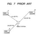
- Fig. 7is a schematic view showing a conventional mobile station locating method.
- a delay time of a received signalis utilized. Namely, delay times ⁇ t1, ⁇ t2 and ⁇ t3 correspond to reciprocative radio propagation times between the mobile station 31 and the base stations 21, 22 and 23, respectively. Using the measured delay times ⁇ t1, ⁇ t2 and ⁇ t3, distances between the mobile station 31 and respective base stations 21, 22 and 23 are calculated. Then, the position of the mobile station 31 is identified based on the calculated distances from three points of respective base stations 21 to 23.
- field intensities R1 to R3represent the attenuation of the radio waves between the mobile station 31 and the base stations 21, 22 and 23, respectively.
- distances between the mobile station 31 and respective base stations 21, 22 and 23are calculated.
- the position of the mobile station 31is identified based on the calculated distances from three points of respective base stations 21 to 23.
- identifying the mobile station's position as a pointis disadvantageous in that a significant amount of calculation error may be caused depending on shifting conditions, such as shifting speed and direction of the mobile station, or radio wave propagating conditions, such as seasons, times, geography, weather, magnetism etc.
- shifting conditionssuch as shifting speed and direction of the mobile station, or radio wave propagating conditions, such as seasons, times, geography, weather, magnetism etc.
- the calculation errortends to be enlarged due to interactions between the above-described various error factors.
- a sophisticated calculation methodwill be required for calculating the delay times or the field intensities. This increases the calculation time largely.
- the present inventionhas an object of providing a mobile station locating method which is capable of enlarging an allowable error range in the calculation and reducing the total calculation time. Furthermore, the presents invention provides a mobile station locating system performing the above-described locating method.
- the present inventionprovides a novel and excellent method for locating a mobile station.
- a plurality of search areaseach being narrower than a radio zone of a base station, are set.
- Each search areais defined by mutual time differences in a radio wave propagation from respective base stations.
- Characteristic signalsare transmitted from respective base stations and received by a mobile station. Time differences caused in the reception of these characteristic signals are used to identify a specific search area where a mobile station is present.
- the present inventionprovides a mobile station locating system with base and mobile stations.
- the base stationcomprises a base station's characteristic signal generating means for generating a characteristic signal, a base station's characteristic signal synchronizing means for controlling a transmitting time of the characteristic signal in synchronism with transmitting times of other characteristic signals of neighboring base stations, a positional information memory means for storing positional information of the search areas, and a positional information calculating means for identifying the specific search area where the mobile station is present based on information sent back from the mobile station in response to reception of the characteristic signal, with reference to the positional information stored in the positional information memory means.
- the mobile stationcomprises a characteristic signal delay time calculating means for calculating time differences in the reception of the characteristic signals transmitted from respective base stations.
- the position of the mobile stationis identified by an area, i.e. a two-dimensional area, not by a point.
- an allowable error range in the calculationcan be enlarged.
- the present inventioncalculates mutual time differences in the reception of the characteristic signals. This makes it possible to reduce the substantial calculation time compared with a case where a radio wave propagation time itself between each base station and the mobile station is used in the calculation.
- a first aspect of the present inventionprovides a method for locating a mobile station based on a mobile communications system, comprising the steps of: setting a plurality of search areas (a1, a2,---) each being narrower than a radio zone (211, 221, 231, 241, or 251) of a base station; defining a positional relationship between each base station and a concerned search area based on mutual time differences in a radio wave propagation between the base stations and the concerned search area; transmitting characteristic signals (d1, d2, d3) from respective base stations (21, 22, 23); obtaining mutual time differences (t12, t23, t13; T12, T23, T13) in the propagation of the characteristic signals caused between transmission of the characteristic signals at respective base stations and reception at a mobile station (31); and identifying a specific search area where the mobile station is present based on the mutual differences between the characteristic signals.
- the position of the mobile stationcan be identified by an area not by a point.
- the base stationstransmit their characteristic signals simultaneously, while the mobile station calculates time differences in a reception of the characteristic signals and sends back a calculated result to the base stations.
- the base stationscan identify a specific search area defined by the time differences calculated by the mobile stations.
- the base stationstransmit the characteristic signals to a target search section, which is successively changed, in such a manner that the characteristic signals arrive the target search area at the same time, while the mobile station sends back a confirmation signal to the base stations when the mobile station receives the characteristic signals simultaneously.
- the base stationscan identify a specific search area based on time differences in the transmitting times of the characteristic signals at respective base stations.
- a second aspect of the present inventionprovides a mobile station locating system for setting a plurality of search areas (a1, a2,---) each being narrower than a radio zone (211, 221, ---, or 251) of a base station (21, 22, ---, or 25) of a mobile communications system and identifying a specific search area where a mobile station is present.
- the mobile station locating systemcomprises base and mobile stations.
- the base station (21)comprises a base station's characteristic signal generating means (41) for generating a characteristic signal (d1) of the base station; a base station's characteristic signal synchronizing means (42) for controlling a transmitting time of the characteristic signal (d1) in synchronism with transmitting times of other characteristic signals (d2, d3) of neighboring base stations (22, 23); a positional information memory means (44) for storing positional information of the search areas: a positional information calculating means (43) for identifying the specific search area where the mobile station (31) is present based on information sent back from the mobile station in response to reception of the characteristic signal, with reference to the positional information stored in the positional information memory means; and a shift hysteresis memory means (45) for storing shift hysteresis of the mobile station.
- a base station's characteristic signal generating means (41)for generating a characteristic signal (d1) of the base station
- a base station's characteristic signal synchronizing means (42)for controlling a transmitting
- the mobile station (31)comprises a characteristic signal delay time calculating means (51) for calculating time differences (t12, t23, t13) in the reception of the characteristic signals transmitted from respective base stations; a positional information output interface means (52) for outputting positional information of the mobile station inquired to the base stations; and a positional information notifying means (53, 54) for notifying positional information of the mobile station obtained from the base station.
- a characteristic signal delay time calculating meansfor calculating time differences (t12, t23, t13) in the reception of the characteristic signals transmitted from respective base stations
- a positional information output interface meansfor outputting positional information of the mobile station inquired to the base stations
- a positional information notifying means53, 54
- the characteristic signal generated from the base station's characteristic signal generating meansis an intrinsic pulse signal allocated to each base station, a modulation signal modulated differently by each base station, or a characteristic frequency signal allocated to each base station.
- the mobile stationreceived the characteristic signals, can discriminate these characteristic signals and calculate mutual time differences in the radio wave propagation between respective base stations.
- the positional information calculating meansidentifies map information, such as latitude/longitude, region name or lot number, representing the specific search area where the mobile station is present based on the positional information stored in the positional information memory means.
- map informationsuch as latitude/longitude, region name or lot number
- the position of the mobile stationcan be indicated by using appropriate latitude/longitude, a region name or a lot number.
- the positional information notifying means of the mobile stationis a sound output device (53) generating voice message including the positional information and/or a character display unit (54) displaying letters representing the positional information.
- a sound output device(53) generating voice message including the positional information and/or a character display unit (54) displaying letters representing the positional information.
- the base stationhas a directional antenna ( ⁇ 1, ⁇ 1) to transmit the characteristic signal.
- ⁇ 1, ⁇ 1the azimuth of the directional antenna can be utilized for identifying the search area.
- the accuracy in the position identificationcan be improved.
- a grid systemis provided to locate a mobile station.
- each two-dimensional (rectangular) section dissected by the grid systemis narrower than a radio zone of each base station 21, 22 or 23.
- This embodimentidentifies a grid section where the mobile station is present.
- the mobile stationmay be present at a grid section (5, b) or (6, b).
- the difference between the grid sections (5, b) and (6, b)can be discriminated by detecting the distance from the mobile station to each base station 21, 22, or 23.
- respective base stations 21, 22 and 23send out position detecting signals (base station's characteristic signals) d1, d2 and d3 simultaneously.
- the mobile stationreceives the base station's characteristic signals sent from base stations.
- a time difference, caused in the reception of the base station's characteristic signals,varies depending on the grid section where the mobile station is present.
- time differencesare memonzed beforehand in relation to each grid section. More specifically, arrival times of the base station's characteristic signals d1, d2 and d3 sent simultaneously from respective base stations 21 to 23 are measured at each grid section. Then, time differences between received signals are stored in a memory. The memorized data in this manner are used later in identifying the present location of the mobile station by comparing actually received base station's characteristic signals with the memorized data.
- Fig. 2shows an arrangement of a communication system performing the above-described mobile station locating method.
- Base stations 21, 22, 23, 24 and 25have their respective radio zones 211, 221, 231, 241 and 251, respectively.
- a plurality of mobile stations 31, 32, 33, 34 and 35are capable of communicating with the base stations 21, 22, 23, 24 and 25.
- These base stations 21, 22, 23, 24 and 25are located in an administration area 111 of a central exchange station 11.
- the central exchange station 11controls all of base stations 21, 22, 23, 24 and 25.
- the central exchange station 11transmits and receives sync signals "b” as well as control signals "c” to and from the base stations 21 to 25 in its administration area 111.
- the sync signals "b”are used to synchronize the base station's characteristic signals "d.”
- the central exchange station 11transmits and receives various signals "a” to and from other exchange stations 12 and 13.
- General subscribers' telephones 9are connected to each exchange station by cable.
- the base stations 21 to 25transmit and receive the control signals "c" to and from the mobile stations 31 to 35 in their respective radio zones. Furthermore, the base stations 21 to 25 transmit and receive the sync signals "b" to and from other base stations. It is assumed that the mobile station 31 is the one to be located by the present invention.
- the base station's characteristic signals d1, d2 and d3are transmitted together with the control signal "c" from base stations 21, 22 and 23 to the mobile station 31.
- the mobile station 31calculates time differences in the reception of respective base station's characteristic signals d1, d2 and d3. Then, a confirmation signal "e" representing a calculation result is sent back to each base station.
- Fig. 3shows a schematic arrangement of each base station employed in this communication system.
- a base station's characteristic signal generator 41generates a base station's characteristic signal.
- a base station's characteristic signal synchronizer 42synchronizes the base station's characteristic signal in response to the sync signal "b.”
- a transmitter/receiver 40transmits and receives the signals.
- a positional information memory 44stores the data relating to the positional information measured beforehand in relation to each grid section.
- a positional information calculator 43converts the confirmation signal received from the mobile station into positional information relating to the grid, with reference to the stored positional data.
- a shift hysteresis memory 45stores hysteresis in the shifting movement of the mobile station.
- the positional information memory 44stores a table describing the range of time differences between the base station's characteristic signals measured at each grid section in connection with the latitude/longitude or a region name or a lot number representing this grid section.
- the positional information calculator 43converts the confirmation signal received from the mobile station into the corresponding latitude/longitude or region mane or the lot number.
- Fig. 4shows a schematic arrangement of the mobile station.
- a characteristic signal delay time calculator 51calculates time differences between received base station's characteristic signals and produces the confirmation signal based on the calculated time differences.
- a transmitter/receiver 50transmits or receives the signals.
- a positional information output interface 52outputs positional information inquired to the base station.
- a sound output device 53generates a voice message including the positional information.
- a character display unit 54displays letters representing the positional information.
- the mobile station 31transmits and receives the control signal "c" to and from the base stations 21, 22 and 23 to register the position of this mobile station 31 to their radio zones. Meanwhile, the field intensity is measured between the mobile station 31 and the base stations 21, 22 and 23. The data relating to the measured field intensities are exchanged with the base stations 21, 22, and 23 together with the control signals. According to the embodiment shown in Fig. 2, the mobile station 31 is registered to the radio zone of the base station 21.
- respective base stations 21, 22 and 23In the exchange of the control signals "c", respective base stations 21, 22 and 23 generate base station's characteristic signals d1, d2 and d3 from their base station's characteristic signal generators 41 under the synchronization control performed by their base station's characteristic signal synchronizers 42.
- the base station's characteristic signals d1, d2 and d3are thus simultaneously transmitted to the mobile station 31.
- the base station's characteristic signals "d”may be an intrinsic pulse signal allocated to each base station, a modulation signal modulated differently by each base station, or a characteristic frequency signal allocated to each base station.
- the mobile station 31needs to receive a plurality of base station's characteristic signals "d" (i.e., d1, d2 and d3) transmitted from at least three base stations (i.e., 21, 22, and 23), except for special cases.
- the radio zones 211, 221, 231, 241 and 251 of the base stationsrequire a strong field intensity of a certain degree to stabilize the communications between the mobile station and the base stations.
- the characteristic signals and confirmation signalswhich are chiefly used for locating the mobile station, can be transmitted under weaker field intensities. Accordingly, the area available such a lower field intensity required for the locating signals is wider than the radio zone of each base station.
- the characteristic signal delay time calculator 51calculates time differences between the received base station's characteristic signals and the transmitter/receiver 50 transmits the confirmation signal "e" to the base station 21 of the radio zone to which the position of the mobile station 31 is registered.
- the base station's characteristic signals d1 to d3are transmitted at the same time from the base stations 21, 22 and 23, respectively.
- the characteristic signal delay time calculator 51 of the mobile station 31calculates a time difference t12 between a reception time t1 of the characteristic signal d1 and a reception time t2 of the characteristic signal d2, a time difference t23 between the reception time t2 of the characteristic signal d2 and a reception time t3 of the characteristic signal d3, and a time difference t13 between the reception time t3 of the characteristic signal d3 and the reception time t1 of the characteristic signal d1.
- the confirmation signal "e"representing the calculated results t12, t23 and t13, is transmitted to the base station 21.
- the characteristic signals's time differences t12, t23 and t13are variable depending on the position of a concerned grid section. In other words, these values are inherent to each grid section. Thus, when a confirmation signal "e" is given, a corresponding grid section can be identified univocally.
- the positional information calculator 43searches or retrieves a confirmation number (b5 in Fig. 1) of a grid section corresponding to the confirmation signal "e” with reference to the positional information data stored in the positional information memory 44. That is, the positional information calculator 43 identifies a corresponding grid section having a time difference range including the time differences t12, t23 and t13 of the base station's characteristic signal represented by the confirmation signal "e.” The searched result is converted into appropriate data, such as latitude/longitude, region name, lot number, which are available as map information.
- the calculated positional informationis stored in the shift hysteresis memory 45 which memorizes the hysteresis in the shifting movement of the mobile station. It is always allowed to refer to the hysteresis data stored in the shift hysteresis memory 45.
- the mobile station 31When the mobile station 31 checks its own position or its shift hysteresis, the mobile station 31 communicates with the base station 21 to which the position of the mobile station 31 is registered and gets the related information stored in the shift hysteresis memory 45.
- the data obtained from the shift hysteresis memory 45are output to the sound output device 53 or to the character display unit 54 via the positional information output interface 52.
- the voices or letters representing the positional informationare generated.
- the base stations 21 to 25can exchange the data stored in their shift hysteresis memories 45 via the central exchange station 11.
- the central exchange station 11 and other exchange stations 12 and 13can exchange the information relating to the shift hysteresis stored in the base stations located in their administration areas. Therefore, the mobile station 31 can check the position or shift hysteresis of its own and other mobile stations 32 to 35 via the base station 21 to which the position of the mobile station 31 is registered.
- the mobile station 31can check the position or shift hysteresis of other mobile stations belonging to other administration area.
- the mobile station 31can check the position or shift hysteresis of any mobile station via each base station or the general subscriber's telephone 9 connected to the exchange station by cable.
- the above-described method for locating a mobile stationidentifies a grid section where an intended mobile station is present. This is robust against an error which may be caused by the mobile station in the calculation of the time difference between the base station's characteristic signals.
- the grid where the mobile station is presentcan be detected accurately even when a calculation error is caused much or less. In other words, an allowable range of the calculation error can be enlarged.
- the mobile stationreceives the base station's characteristic signals transmitted from at least three base stations.
- the number of the base stations from which the base station's characteristic signals are transmittedcan be reduced, when a large error range is allowed or when a position detecting error can be compensated later.
- using a directional antenna shown in a later-described third embodimentis effective to compensate the position detecting error.
- timing for locating the mobile stationis not limited to the registration of the position of the mobile station and therefore can be performed anytime.
- a second embodiment of the present inventionrelates to a mobile station locating method which is capable of reducing the burden of the mobile station.
- the mobile station locating method in accordance with the second embodimentcan be realized by the same arrangement as that of the first embodiment.
- the base station's characteristic signals d1, d2 and d3 transmitted from respective base stationsarrive a target grid section at the same time.
- respective base stationsmutually control the transmitting timings of their base station's characteristic signals d1, d2 and d3. Similar adjustment is performed for each of grid sections.
- each base stationtransmits the base station's characteristic signal in accordance with the adjusted timing.
- a delay time of T23is provided before the base station 22 transmits the base station's characteristic signal d2.
- the base station's characteristic signal synchronizer 42controls the provision of the delay time T23 so that the base station's characteristic signals d2 and d3 arrive the grid section (5, b) at the same time.
- a delay time of T12is provided before the base station 21 transmits the base station's characteristic signal d1.
- the base station's characteristic signal synchronizer 42controls the provision of the delay time T12 so that the base station's characteristic signals d1 and d2 arrive the grid section (5, b) at the same time.
- a delay time of T13is provided before the base station 21 transmits the base station's characteristic signal dl.
- a predetermined time intervalis provided.
- the base stations 21, 22 and 23transmit the base station's characteristic signals d1, d2 and d3 under the control of their transmission timings, so that the base station's characteristic signals d1, d2 and d3 arrive the next grid section (5, c) at the same time.
- the transmitting operations of the base stations 21, 22 and 23are repetitively performed for each target grid sections which is successively changed.
- the mobile station 31receives the base station's characteristic signals d1, d2 and d3 transmitted from the base stations 21, 22 and 23, respectively.
- the mobile station 31transmits the confirmation signal "e" to the base station 21.
- the recognition numberis converted into the corresponding data of latitude/longitude, region name, or lot number representing the identified grid section.
- the shift hysteresis memory 45stores the hysteresis data relating to the shifting movement of the mobile station.
- the above-described mobile station locating methodmakes it possible to detect the position of the mobile station easily.
- the mobile stationdetects its position by solely confirming whether the base station's characteristic signals dl to d3 have arrived within a predetermined time difference. Compared with the method of the first embodiment, the burden of the mobile station for the calculation can be reduced.
- a third embodiment of the present inventionrelates to a mobile station locating method which utilizes a directional antenna to increase the accuracy in the locating of the mobile station.
- Fig. 6shows a base station of this locating system.
- a directional antenna having a beam angle ⁇ 1is used to transmit the base station's characteristic signals "d" and the control signals "c.”
- ⁇ 1represents an azimuth of the directional antenna
- the base station's characteristic signal "d”is transmitted with a narrower angular zone ⁇ 1 having its center on an angular position ⁇ 1.
- the base stationidentifies a grid section where a concerned mobile station is present by using the locating method explained in the first or second embodiment. In this case, the accuracy in the position identification can be improved by processing the information involved in the confirmation signal "e" sent from the mobile station together with the azimuth information ⁇ 1 of the directional antenna. As a result, it becomes possible to reduce the number of base stations transmitting the base station's characteristic signals to the mobile station for the locating of the mobile station.
- the present inventionidentifies the grid section (i.e., two-dimensional area) where the mobile station is present. Accordingly, it becomes possible to enlarge an allowable error range in the locating calculation. The requirement to the calculation accuracy can be moderated and the calculation burden can be reduced.
- the mobile station locating method of the present inventionadopts a method for identifying the grid section based on mutual time differences in the radio wave propagation between respective base stations and the concerned grid section. This makes it possible to reduce the substantial amount and time required in the calculations for the locating of the mobile station compared with a case where a delay time is calculated based on an actual radio wave propagation time between each base station and the grid section or based on a reciprocative radio wave propagation time between them.
- the present inventionadopts the mobile station locating method for controlling the transmitting timings of the base station's characteristic signals so that the base station's characteristic signals arrive the target grid section at the same time. According to this method, it becomes possible to reduce the calculation burden of the mobile station. Thus, the mobile station needs not expand its scale or capacity.
- the mobile station locating method of the present inventionit becomes possible to effectively locate the mobile station.
- the directional antennawhen the directional antenna is employed in the base station, it becomes possible to improve the accuracy in the identification of the position of the mobile station.
Landscapes
- Engineering & Computer Science (AREA)
- Physics & Mathematics (AREA)
- General Physics & Mathematics (AREA)
- Radar, Positioning & Navigation (AREA)
- Remote Sensing (AREA)
- Computer Networks & Wireless Communication (AREA)
- Signal Processing (AREA)
- Mobile Radio Communication Systems (AREA)
- Position Fixing By Use Of Radio Waves (AREA)
Abstract
Description
The present invention relates to a mobile station locating method forlocating a mobile station by utilizing a mobile communication system and alsorelates to a mobile station locating system for realizing this method.Specifically, the present invention makes it possible to reduce the burden in thecalculation (amount and time) required for this locating operation.
According to a conventional mobile communication system, a stablecommunication between a mobile station and a base station is performed in thefollowing manner. The mobile station measures a field intensity of a radiotransmitting line to each neighboring base station, and selects a desirable basestation having the highest field intensity. Then, the position of the mobilestation is registered in a radio zone of the selected base station. In this manner,a stable radio transmitting line is secured between the mobile station and anoptimum base station.
Furthermore, after having secured the most reliable radio transmittingline to the optimum base station, the mobile station intermittently executes themeasurement of the field intensity etc. Due to a shift movement of the mobilestation, the field intensity to the present base station may become weaker thana field intensity to other base station. This will decrease the reliability ofcommunications significantly. In such a case, the registration of the mobilestation's position is renewed from the present station to the next station. Then,the radio transmitting line is switched to a new station. In this manner, anoptimum communication line is always secured.
However, according to the conventional mobile communication system,the position of the mobile station can be roughly grasped by the size of a radiozone of a base station. It is however impossible to identify the position of themobile station precisely at the units of a smaller area.
If identifying the position of the mobile station is feasible, it becomespossible to utilize the positional information of own or a desired mobile stationby accessing from the mobile station or via a general telephone. The obtainedpositional information can be used in various ways. Furthermore, the basestation can memorize the positional information of the mobile station. Thestored positional information can be utilized as useful data in the processing ofvarious information, such as utilization rate or statistical processing of mobilestations in the radio zone.
Identifying the position of the mobile station can be realized by utilizinga GPS which is widely used these days. In this case, the mobile station needsto incorporate a new system which has not ever used. In view of the foregoing,to identify the position of the mobile station, it is preferable that the mobilestation can utilize existing functions of a conventional mobile communicationsystem without largely modifying the existing system. Some methods havebeen always proposed.
According to Unexamined Japanese Patent Application No. 7-38951, amobile station transmits a position detecting signal including information forself-identification. At least three neighboring base stations receive this signaland detect a field intensity of the received signal. A central exchange station,connected to each base station, calculates a position of the mobile stationbased on the information relating to the field intensity of the received signalsupplied from each base station. According to this prior art, the centralexchange station calculates a distance between the mobile station and each base station based on the field intensity of the received signal. A circle with itscenter on each base station and having a radius identical with the calculateddistance is drawn with respect to each base station. Then, an intersection of thedrawn circles is identified as the position of the mobile station.
Furthermore, according to Unexamined Japanese Patent Application No.3-235077, at least three base stations communicate with a mobile station. Adelay time, which corresponds to a time required for a reciprocative radiowave propagation between each base station and the mobile station, iscalculated. Then, based on the delay time obtained in each base station, theposition of the mobile station is calculated.
However, the above-described mobile station locating methods arecharacterized in that the position of the mobile station is obtained as a point,and therefore disadvantageous in that a long calculating time is required anda large calculation error may be caused.
Fig. 7 is a schematic view showing a conventional mobile stationlocating method. According to one method for identifying the position of amobile station 31, a delay time of a received signal is utilized. Namely, delaytimes Δt1, Δt2 and Δt3 correspond to reciprocative radio propagation timesbetween themobile station 31 and thebase stations mobile station 31 andrespective base stations mobile station 31 is identified based on thecalculated distances from three points ofrespective base stations 21 to 23.
According to the other method for identifying the position of themobilestation 31, a field intensity of the received signal is utilized. Namely, fieldintensities R1 to R3 represent the attenuation of the radio waves between themobile station 31 and thebase stations mobile station 31andrespective base stations mobile station 31 is identified based on the calculated distances fromthree points ofrespective base stations 21 to 23.
However, identifying the mobile station's position as a point isdisadvantageous in that a significant amount of calculation error may be causeddepending on shifting conditions, such as shifting speed and direction of themobile station, or radio wave propagating conditions, such as seasons, times,geography, weather, magnetism etc. Especially, in a mobile communicationsystem utilizing microwaves, the calculation error tends to be enlarged due tointeractions between the above-described various error factors. Furthermore,when the calculation error needs to be reduced as small as possible, asophisticated calculation method will be required for calculating the delaytimes or the field intensities. This increases the calculation time largely.
To solve the above-described conventional problems, the presentinvention has an object of providing a mobile station locating method whichis capable of enlarging an allowable error range in the calculation and reducingthe total calculation time. Furthermore, the presents invention provides amobile station locating system performing the above-described locatingmethod.
In order to accomplish the above-described and other related objects,the present invention provides a novel and excellent method for locating amobile station. A plurality of search areas, each being narrower than a radiozone of a base station, are set. Each search area is defined by mutual time differences in a radio wave propagation from respective base stations.Characteristic signals are transmitted from respective base stations andreceived by a mobile station. Time differences caused in the reception of thesecharacteristic signals are used to identify a specific search area where a mobilestation is present.
The present invention provides a mobile station locating system withbase and mobile stations. The base station comprises a base station'scharacteristic signal generating means for generating a characteristic signal, abase station's characteristic signal synchronizing means for controlling atransmitting time of the characteristic signal in synchronism with transmittingtimes of other characteristic signals of neighboring base stations, a positionalinformation memory means for storing positional information of the searchareas, and a positional information calculating means for identifying thespecific search area where the mobile station is present based on informationsent back from the mobile station in response to reception of the characteristicsignal, with reference to the positional information stored in the positionalinformation memory means. The mobile station comprises a characteristicsignal delay time calculating means for calculating time differences in thereception of the characteristic signals transmitted from respective base stations.
According to the present invention, the position of the mobile station isidentified by an area, i.e. a two-dimensional area, not by a point. Thus, anallowable error range in the calculation can be enlarged. Furthermore, thepresent invention calculates mutual time differences in the reception of thecharacteristic signals. This makes it possible to reduce the substantialcalculation time compared with a case where a radio wave propagation timeitself between each base station and the mobile station is used in thecalculation.
More specifically, a first aspect of the present invention provides amethod for locating a mobile station based on a mobile communicationssystem, comprising the steps of: setting a plurality of search areas (a1, a2,---)each being narrower than a radio zone (211, 221, 231, 241, or 251) of a basestation; defining a positional relationship between each base station and aconcerned search area based on mutual time differences in a radio wavepropagation between the base stations and the concerned search area;transmitting characteristic signals (d1, d2, d3) from respective base stations(21, 22, 23); obtaining mutual time differences (t12, t23, t13; T12, T23, T13)in the propagation of the characteristic signals caused between transmission ofthe characteristic signals at respective base stations and reception at a mobilestation (31); and identifying a specific search area where the mobile station ispresent based on the mutual differences between the characteristic signals.Thus, the position of the mobile station can be identified by an area not by apoint.
Preferably, the base stations transmit their characteristic signalssimultaneously, while the mobile station calculates time differences in areception of the characteristic signals and sends back a calculated result to thebase stations. Thus, the base stations can identify a specific search area definedby the time differences calculated by the mobile stations.
Preferably, the base stations transmit the characteristic signals to a targetsearch section, which is successively changed, in such a manner that thecharacteristic signals arrive the target search area at the same time, while themobile station sends back a confirmation signal to the base stations when themobile station receives the characteristic signals simultaneously. Thus, the basestations can identify a specific search area based on time differences in thetransmitting times of the characteristic signals at respective base stations.
A second aspect of the present invention provides a mobile stationlocating system for setting a plurality of search areas (a1, a2,---) each beingnarrower than a radio zone (211, 221, ---, or 251) of a base station (21, 22, ---,or 25) of a mobile communications system and identifying a specific searcharea where a mobile station is present. The mobile station locating systemcomprises base and mobile stations. The base station (21) comprises a basestation's characteristic signal generating means (41) for generating acharacteristic signal (d1) of the base station; a base station's characteristicsignal synchronizing means (42) for controlling a transmitting time of thecharacteristic signal (d1) in synchronism with transmitting times of othercharacteristic signals (d2, d3) of neighboring base stations (22, 23); apositional information memory means (44) for storing positional informationof the search areas: a positional information calculating means (43) foridentifying the specific search area where the mobile station (31) is presentbased on information sent back from the mobile station in response toreception of the characteristic signal, with reference to the positionalinformation stored in the positional information memory means; and a shifthysteresis memory means (45) for storing shift hysteresis of the mobile station.On the other hand, the mobile station (31) comprises a characteristic signaldelay time calculating means (51) for calculating time differences (t12, t23,t13) in the reception of the characteristic signals transmitted from respectivebase stations; a positional information output interface means (52) foroutputting positional information of the mobile station inquired to the basestations; and a positional information notifying means (53, 54) for notifyingpositional information of the mobile station obtained from the base station.With this system, the above-described mobile station locating method can beperformed.
Preferably, the characteristic signal generated from the base station'scharacteristic signal generating means is an intrinsic pulse signal allocated toeach base station, a modulation signal modulated differently by each basestation, or a characteristic frequency signal allocated to each base station. Themobile station, received the characteristic signals, can discriminate thesecharacteristic signals and calculate mutual time differences in the radio wavepropagation between respective base stations.
Preferably, the positional information calculating means identifies mapinformation, such as latitude/longitude, region name or lot number,representing the specific search area where the mobile station is present basedon the positional information stored in the positional information memorymeans. Thus, the position of the mobile station can be indicated by usingappropriate latitude/longitude, a region name or a lot number.
Preferably, the positional information notifying means of the mobilestation is a sound output device (53) generating voice message including thepositional information and/or a character display unit (54) displaying lettersrepresenting the positional information. Thus, it becomes possible to realize asound or character display of the position of own or an intended mobile stationby requesting the base station.
Preferably, the base station has a directional antenna (1, 1) totransmit the characteristic signal. With this arrangement, the azimuth of thedirectional antenna can be utilized for identifying the search area. Thus, theaccuracy in the position identification can be improved.
Reference numerals in parentheses added in the foregoing descriptionshow the correspondence to the components disclosed in preferredembodiments of the present invention. Thus, the reference numerals are merelyused for expediting the understanding to the present invention and not used for narrowly interpreting the scope of the present invention.
The above and other objects, features and advantages of the presentinvention will become more apparent from the following detailed descriptionwhich is to be read in conjunction with the accompanying drawings, in which:
Preferred embodiments of the present invention will be explained inmore detail with reference to Figs. 1 through 6. Identical parts are denoted bythe same reference numerals throughout the drawing.
According to a mobile station locating method in accordance with a firstembodiment, a grid system is provided to locate a mobile station. As shown inFig. 1, each two-dimensional (rectangular) section dissected by the grid systemis narrower than a radio zone of eachbase station
For example, the mobile station may be present at a grid section (5, b)or (6, b). The difference between the grid sections (5, b) and (6, b) can bediscriminated by detecting the distance from the mobile station to eachbasestation respective base stations
According to this mobile station locating method, time differences arememonzed beforehand in relation to each grid section. More specifically,arrival times of the base station's characteristic signals d1, d2 and d3 sentsimultaneously fromrespective base stations 21 to 23 are measured at eachgrid section. Then, time differences between received signals are stored in a memory. The memorized data in this manner are used later in identifying thepresent location of the mobile station by comparing actually received basestation's characteristic signals with the memorized data.
Fig. 2 shows an arrangement of a communication system performing theabove-described mobile station locating method.Base stations respective radio zones mobile stations base stations basestations administration area 111 of acentral exchange station 11. Thecentral exchange station 11 controls all ofbase stations
Thecentral exchange station 11 transmits and receives sync signals "b"as well as control signals "c" to and from thebase stations 21 to 25 in itsadministration area 111. The sync signals "b" are used to synchronize the basestation's characteristic signals "d." Furthermore, thecentral exchange station 11 transmits and receives various signals "a" to and fromother exchangestations telephones 9 are connected to eachexchange station by cable.
Thebase stations 21 to 25 transmit and receive the control signals "c"to and from themobile stations 31 to 35 in their respective radio zones.Furthermore, thebase stations 21 to 25 transmit and receive the sync signals"b" to and from other base stations. It is assumed that themobile station 31 isthe one to be located by the present invention. The base station's characteristicsignals d1, d2 and d3 are transmitted together with the control signal "c" frombase stations mobile station 31. Themobile station 31calculates time differences in the reception of respective base station'scharacteristic signals d1, d2 and d3. Then, a confirmation signal "e" representing a calculation result is sent back to each base station.
Fig. 3 shows a schematic arrangement of each base station employed inthis communication system. A base station'scharacteristic signal generator 41generates a base station's characteristic signal. A base station'scharacteristicsignal synchronizer 42 synchronizes the base station's characteristic signal inresponse to the sync signal "b." A transmitter/receiver 40 transmits andreceives the signals. Apositional information memory 44 stores the datarelating to the positional information measured beforehand in relation to eachgrid section. Apositional information calculator 43 converts the confirmationsignal received from the mobile station into positional information relating tothe grid, with reference to the stored positional data. Ashift hysteresis memory 45 stores hysteresis in the shifting movement of the mobile station.
Thepositional information memory 44 stores a table describing therange of time differences between the base station's characteristic signalsmeasured at each grid section in connection with the latitude/longitude or aregion name or a lot number representing this grid section. Thepositionalinformation calculator 43 converts the confirmation signal received from themobile station into the corresponding latitude/longitude or region mane or thelot number.
Fig. 4 shows a schematic arrangement of the mobile station. Acharacteristic signaldelay time calculator 51 calculates time differencesbetween received base station's characteristic signals and produces theconfirmation signal based on the calculated time differences. Atransmitter/receiver 50 transmits or receives the signals. A positionalinformation output interface 52 outputs positional information inquired to thebase station. Asound output device 53 generates a voice message including thepositional information. Acharacter display unit 54 displays letters representing the positional information.
An operation of this system, especially functions of themobile station 31, will be explained.
First, themobile station 31 transmits and receives the control signal "c"to and from thebase stations mobile station 31 to their radio zones. Meanwhile, the field intensity ismeasured between themobile station 31 and thebase stations basestations mobile station 31 is registered to the radiozone of thebase station 21.
In the exchange of the control signals "c",respective base stations characteristic signal generators 41 under thesynchronization control performed by their base station'scharacteristic signalsynchronizers 42. The base station's characteristic signals d1, d2 and d3 arethus simultaneously transmitted to themobile station 31. The base station'scharacteristic signals "d" may be an intrinsic pulse signal allocated to eachbase station, a modulation signal modulated differently by each base station,or a characteristic frequency signal allocated to each base station.
To identify the present grid section, themobile station 31 needs toreceive a plurality of base station's characteristic signals "d" (i.e., d1, d2 andd3) transmitted from at least three base stations (i.e., 21, 22, and 23), exceptfor special cases. Theradio zones
After themobile station 31 received the base station's characteristicsignals d1 to d3, the characteristic signaldelay time calculator 51 calculatestime differences between the received base station's characteristic signals andthe transmitter/receiver 50 transmits the confirmation signal "e" to thebasestation 21 of the radio zone to which the position of themobile station 31 isregistered.
More specifically, as shown in Fig. 5A, the base station's characteristicsignals d1 to d3 are transmitted at the same time from thebase stations delay time calculator 51 of themobile station 31 calculates a time difference t12 between a reception time t1of the characteristic signal d1 and a reception time t2 of the characteristicsignal d2, a time difference t23 between the reception time t2 of thecharacteristic signal d2 and a reception time t3 of the characteristic signal d3,and a time difference t13 between the reception time t3 of the characteristicsignal d3 and the reception time t1 of the characteristic signal d1. Theconfirmation signal "e", representing the calculated results t12, t23 and t13, istransmitted to thebase station 21.
The characteristic signals's time differences t12, t23 and t13 are variabledepending on the position of a concerned grid section. In other words, thesevalues are inherent to each grid section. Thus, when a confirmation signal "e"is given, a corresponding grid section can be identified univocally.
When thebase station 21 receives the confirmation signal "e", thepositional information calculator 43 searches or retrieves a confirmationnumber (b5 in Fig. 1) of a grid section corresponding to the confirmation signal "e" with reference to the positional information data stored in thepositionalinformation memory 44. That is, thepositional information calculator 43identifies a corresponding grid section having a time difference range includingthe time differences t12, t23 and t13 of the base station's characteristic signalrepresented by the confirmation signal "e." The searched result is convertedinto appropriate data, such as latitude/longitude, region name, lot number,which are available as map information.
The calculated positional information is stored in theshift hysteresismemory 45 which memorizes the hysteresis in the shifting movement of themobile station. It is always allowed to refer to the hysteresis data stored in theshift hysteresis memory 45.
When themobile station 31 checks its own position or its shifthysteresis, themobile station 31 communicates with thebase station 21 towhich the position of themobile station 31 is registered and gets the relatedinformation stored in theshift hysteresis memory 45. The data obtained fromtheshift hysteresis memory 45 are output to thesound output device 53 or tothecharacter display unit 54 via the positionalinformation output interface 52.Thus, the voices or letters representing the positional information aregenerated.
Furthermore, thebase stations 21 to 25 can exchange the data stored intheirshift hysteresis memories 45 via thecentral exchange station 11. Thecentral exchange station 11 andother exchange stations mobile station 31can check the position or shift hysteresis of its own and othermobile stations 32 to 35 via thebase station 21 to which the position of themobile station 31is registered. Moreover, themobile station 31 can check the position or shift hysteresis of other mobile stations belonging to other administration area.Furthermore, themobile station 31 can check the position or shift hysteresis ofany mobile station via each base station or the general subscriber'stelephone 9 connected to the exchange station by cable.
In this manner, the above-described method for locating a mobile stationidentifies a grid section where an intended mobile station is present. This isrobust against an error which may be caused by the mobile station in thecalculation of the time difference between the base station's characteristicsignals. The grid where the mobile station is present can be detected accuratelyeven when a calculation error is caused much or less. In other words, anallowable range of the calculation error can be enlarged.
According to the above-described embodiment, the mobile stationreceives the base station's characteristic signals transmitted from at least threebase stations. However, the number of the base stations from which the basestation's characteristic signals are transmitted can be reduced, when a largeerror range is allowed or when a position detecting error can be compensatedlater. For example, using a directional antenna shown in a later-described thirdembodiment is effective to compensate the position detecting error.
Furthermore, the timing for locating the mobile station is not limited tothe registration of the position of the mobile station and therefore can beperformed anytime.
A second embodiment of the present invention relates to a mobile stationlocating method which is capable of reducing the burden of the mobile station.The mobile station locating method in accordance with the second embodimentcan be realized by the same arrangement as that of the first embodiment.
According to the locating method of the second embodiment, as shown in Fig. 5B, the base station's characteristic signals d1, d2 and d3 transmittedfrom respective base stations arrive a target grid section at the same time. Tothis end, respective base stations mutually control the transmitting timings oftheir base station's characteristic signals d1, d2 and d3. Similar adjustment isperformed for each of grid sections. Thus, by successively changing the targetgrid section, each base station transmits the base station's characteristic signalin accordance with the adjusted timing.
For example, after thebase station 23 transmits the base station'scharacteristic signal d3, a delay time of T23 is provided before thebase station 22 transmits the base station's characteristic signal d2. The base station'scharacteristic signal synchronizer 42 controls the provision of the delay timeT23 so that the base station's characteristic signals d2 and d3 arrive the gridsection (5, b) at the same time. In the same manner, after thebase station 22transmits the base station's characteristic signal d2, a delay time of T12 isprovided before thebase station 21 transmits the base station's characteristicsignal d1. The base station'scharacteristic signal synchronizer 42 controls theprovision of the delay time T12 so that the base station's characteristic signalsd1 and d2 arrive the grid section (5, b) at the same time. In other words, afterthebase station 23 transmits the base station's characteristic signal d3, a delaytime of T13 is provided before thebase station 21 transmits the base station'scharacteristic signal dl. Subsequently, a predetermined time interval isprovided. After the predetermined time has passed, thebase stations base stations
On the other hand, themobile station 31 receives the base station'scharacteristic signals d1, d2 and d3 transmitted from thebase stations mobilestation 31 transmits the confirmation signal "e" to thebase station 21.
Thebase station 21, after received the confirmation signal "e", identifiesa recognition number of a present grid section based on the transmission timedifferences T12, T23 and T13 for the base station's characteristic signalstransmitted last from thebase stations 21 to 23. The recognition number isconverted into the corresponding data of latitude/longitude, region name, or lotnumber representing the identified grid section. Theshift hysteresis memory 45 stores the hysteresis data relating to the shifting movement of the mobilestation.
As apparent from the foregoing description, the above-described mobilestation locating method makes it possible to detect the position of the mobilestation easily. The mobile station detects its position by solely confirmingwhether the base station's characteristic signals dl to d3 have arrived withina predetermined time difference. Compared with the method of the firstembodiment, the burden of the mobile station for the calculation can bereduced.
A third embodiment of the present invention relates to a mobile stationlocating method which utilizes a directional antenna to increase the accuracyin the locating of the mobile station.
Fig. 6 shows a base station of this locating system. A directional antennahaving a beam angle 1 is used to transmit the base station's characteristicsignals "d" and the control signals "c." When 1 represents an azimuth of the directional antenna, the base station's characteristic signal "d" is transmittedwith a narrower angular zone 1 having its center on an angular position 1.The base station identifies a grid section where a concerned mobile station ispresent by using the locating method explained in the first or secondembodiment. In this case, the accuracy in the position identification can beimproved by processing the information involved in the confirmation signal "e"sent from the mobile station together with the azimuth information 1 of thedirectional antenna. As a result, it becomes possible to reduce the number ofbase stations transmitting the base station's characteristic signals to the mobilestation for the locating of the mobile station.
As apparent from the foregoing description, according to the mobilestation locating method of the present invention, there is no necessity ofidentifying the position of the mobile station as a point, as was so in the priorart. Instead, the present invention identifies the grid section (i.e., two-dimensionalarea) where the mobile station is present. Accordingly, it becomespossible to enlarge an allowable error range in the locating calculation. Therequirement to the calculation accuracy can be moderated and the calculationburden can be reduced.
Furthermore, the mobile station locating method of the present inventionadopts a method for identifying the grid section based on mutual timedifferences in the radio wave propagation between respective base stations andthe concerned grid section. This makes it possible to reduce the substantialamount and time required in the calculations for the locating of the mobilestation compared with a case where a delay time is calculated based on anactual radio wave propagation time between each base station and the gridsection or based on a reciprocative radio wave propagation time between them.
Moreover, the present invention adopts the mobile station locating method for controlling the transmitting timings of the base station'scharacteristic signals so that the base station's characteristic signals arrive thetarget grid section at the same time. According to this method, it becomespossible to reduce the calculation burden of the mobile station. Thus, themobile station needs not expand its scale or capacity.
Furthermore, according to the mobile station locating method of thepresent invention, it becomes possible to effectively locate the mobile station.
Moreover, when the directional antenna is employed in the base station,it becomes possible to improve the accuracy in the identification of the positionof the mobile station.
This invention may be embodied in several forms without departing fromthe spirit of essential characteristics thereof. The present embodiments asdescribed are therefore intended to be only illustrative and not restrictive, sincethe scope of the invention is defined by the appended claims rather than by thedescription preceding them. All changes that fall within the metes and boundsof the claims, or equivalents of such metes and bounds, are therefore intendedto be embraced by the claims.
Claims (8)
- A method for locating a mobile station based on a mobilecommunications system, characterized by the steps of:setting a plurality of search areas (a1, a2,---) each being narrower thana radio zone (211, 221,----, or 251) of a base station (21, 22,----, or 25);defining a positional relationship between each base station and aconcerned search area based on mutual time differences in a radio wavepropagation between base stations and said concerned search area;transmitting characteristic signals (d1, d2, d3) from respective basestations (21, 22, 23) to obtain mutual time differences (t12, t23, t13; T12, T23,T13) in the propagation of said characteristic signals caused betweentransmission of said characteristic signals at respective base stations andreception at a mobile station (31); andidentifying a specific search area where said mobile station is presentbased on said mutual time differences between said characteristic signals.
- The mobile station locating method in accordance with claim 1,wherein said base stations transmit said characteristic signals simultaneously,while said mobile station calculates time differences in a reception of saidcharacteristic signals and sends back a calculated result to said base stations.
- The mobile station locating method in accordance with claim 1,wherein said base stations transmit said characteristic signals to a target searchsection, which is successively changed, in such a manner that saidcharacteristic signals arrive the target search area at the same time, while saidmobile station sends back a confirmation signal to said base stations when said mobile station receives said characteristic signals simultaneously.
- A mobile station locating system for setting a plurality of search areas(a1, a2,---) each being narrower than a radio zone (211, 221, ---, or 251) of abase station of a mobile communications system and identifying a specificsearch area where a mobile station (31) is present, characterized bya base station (21) including:base station's characteristic signal generating means (41) for generatinga characteristic signal (d1) of said base station;base station's characteristic signal synchronizing means (52) forcontrolling a transmitting time of said characteristic signal in synchronism withtransmitting times of other characteristic signals (d2, d3) of neighboring basestations (22, 23);positional information memory means (44) for storing positionalinformation of said search areas:positional information calculating means (43) for identifying saidspecific search area where said mobile station is present based on informationsent back from said mobile station in response to reception of saidcharacteristic signal, with reference to said positional information stored in saidpositional information memory means; andshift hysteresis memory means (45) for storing shift hysteresis of saidmobile station, andsaid mobile station (31) including:characteristic signal delay time calculating means (51) for calculatingtime differences (t12, t23, t13) in the reception of said characteristic signals(d1, d2, d3) transmitted from respective base stations (21, 22, 23);positional information output interface means (52) for outputting positional information of said mobile station inquired to said base stations; andpositional information notifying means (53, 54) for notifying positionalinformation of said mobile station obtained from said base station.
- The mobile station locating system in accordance with claim 4,wherein said characteristic signal generated from said base station'scharacteristic signal generating means is an intrinsic pulse signal allocated toeach base station, a modulation signal modulated differently by each basestation, or a characteristic frequency signal allocated to each base station.
- The mobile station locating system in accordance with claim 4 or claim 5,wherein said positional information calculating means identifies mapinformation, such as latitude/longitude, region name or lot number,representing said specific search area where said mobile station is presentbased on the positional information stored in said positional informationmemory means.
- The mobile station locating system in accordance with claim 4, 5 or 6,wherein said positional information notifying means of said mobile station isa sound output device (53) generating voice message including said positionalinformation and/or a character display unit (54) displaying letters representingsaid positional information.
- The mobile station locating system in accordance with claim 4, 5, 6 or 7,wherein said base station has a directional antenna (1, 1) to transmit saidcharacteristic signal.
Applications Claiming Priority (3)
| Application Number | Priority Date | Filing Date | Title |
|---|---|---|---|
| JP03142597AJP3260649B2 (en) | 1997-01-31 | 1997-01-31 | Mobile station location search method and mobile station location search system |
| JP3142597 | 1997-01-31 | ||
| JP31425/97 | 1997-01-31 |
Publications (2)
| Publication Number | Publication Date |
|---|---|
| EP0856746A2true EP0856746A2 (en) | 1998-08-05 |
| EP0856746A3 EP0856746A3 (en) | 1999-07-28 |
Family
ID=12330898
Family Applications (1)
| Application Number | Title | Priority Date | Filing Date |
|---|---|---|---|
| EP98300447AWithdrawnEP0856746A3 (en) | 1997-01-31 | 1998-01-22 | Method and system for locating a mobile station |
Country Status (4)
| Country | Link |
|---|---|
| US (1) | US6108556A (en) |
| EP (1) | EP0856746A3 (en) |
| JP (1) | JP3260649B2 (en) |
| CN (1) | CN1092456C (en) |
Cited By (39)
| Publication number | Priority date | Publication date | Assignee | Title |
|---|---|---|---|---|
| WO2002035875A1 (en)* | 2000-10-20 | 2002-05-02 | Motorola Inc | Mobile station and method of locating the mobile station |
| WO2003039183A1 (en)* | 2001-11-01 | 2003-05-08 | Unwiredfactory A/S | Methods, systems and computer program products for dividing a physical domain |
| WO2010149796A1 (en) | 2009-06-26 | 2010-12-29 | Masat B.V. | Method and system for determining the location of a moving sensor node |
| WO2011106563A1 (en)* | 2010-02-25 | 2011-09-01 | At & T Mobility Ii Llc | Timed fingerprint locating in wireless networks |
| US8254959B2 (en) | 2010-02-25 | 2012-08-28 | At&T Mobility Ii Llc | Timed fingerprint locating for idle-state user equipment in wireless networks |
| EP2498557A1 (en)* | 2011-03-08 | 2012-09-12 | Alcatel Lucent | Apparatus and method for synchronising a mobile station with a base station |
| US8326319B2 (en) | 2009-01-23 | 2012-12-04 | At&T Mobility Ii Llc | Compensation of propagation delays of wireless signals |
| US20130115915A1 (en)* | 2011-11-08 | 2013-05-09 | At&T Intellectual Property I, L.P. | Location based sharing of a network access credential |
| US8509806B2 (en) | 2010-12-14 | 2013-08-13 | At&T Intellectual Property I, L.P. | Classifying the position of a wireless device |
| US8612410B2 (en) | 2011-06-30 | 2013-12-17 | At&T Mobility Ii Llc | Dynamic content selection through timed fingerprint location data |
| US8666390B2 (en) | 2011-08-29 | 2014-03-04 | At&T Mobility Ii Llc | Ticketing mobile call failures based on geolocated event data |
| US8762048B2 (en) | 2011-10-28 | 2014-06-24 | At&T Mobility Ii Llc | Automatic travel time and routing determinations in a wireless network |
| US8761799B2 (en) | 2011-07-21 | 2014-06-24 | At&T Mobility Ii Llc | Location analytics employing timed fingerprint location information |
| US8892112B2 (en) | 2011-07-21 | 2014-11-18 | At&T Mobility Ii Llc | Selection of a radio access bearer resource based on radio access bearer resource historical information |
| US8892054B2 (en) | 2012-07-17 | 2014-11-18 | At&T Mobility Ii Llc | Facilitation of delay error correction in timing-based location systems |
| US8897802B2 (en) | 2011-07-21 | 2014-11-25 | At&T Mobility Ii Llc | Selection of a radio access technology resource based on radio access technology resource historical information |
| US8897805B2 (en) | 2012-06-15 | 2014-11-25 | At&T Intellectual Property I, L.P. | Geographic redundancy determination for time based location information in a wireless radio network |
| US8923134B2 (en) | 2011-08-29 | 2014-12-30 | At&T Mobility Ii Llc | Prioritizing network failure tickets using mobile location data |
| US8925104B2 (en) | 2012-04-13 | 2014-12-30 | At&T Mobility Ii Llc | Event driven permissive sharing of information |
| US8929827B2 (en) | 2012-06-04 | 2015-01-06 | At&T Mobility Ii Llc | Adaptive calibration of measurements for a wireless radio network |
| US8938258B2 (en) | 2012-06-14 | 2015-01-20 | At&T Mobility Ii Llc | Reference based location information for a wireless network |
| US8970432B2 (en) | 2011-11-28 | 2015-03-03 | At&T Mobility Ii Llc | Femtocell calibration for timing based locating systems |
| US8996031B2 (en) | 2010-08-27 | 2015-03-31 | At&T Mobility Ii Llc | Location estimation of a mobile device in a UMTS network |
| US9008684B2 (en) | 2010-02-25 | 2015-04-14 | At&T Mobility Ii Llc | Sharing timed fingerprint location information |
| US9009629B2 (en) | 2010-12-01 | 2015-04-14 | At&T Mobility Ii Llc | Motion-based user interface feature subsets |
| US9026133B2 (en) | 2011-11-28 | 2015-05-05 | At&T Mobility Ii Llc | Handset agent calibration for timing based locating systems |
| US9046592B2 (en) | 2012-06-13 | 2015-06-02 | At&T Mobility Ii Llc | Timed fingerprint locating at user equipment |
| US9053513B2 (en) | 2010-02-25 | 2015-06-09 | At&T Mobility Ii Llc | Fraud analysis for a location aware transaction |
| US9094929B2 (en) | 2012-06-12 | 2015-07-28 | At&T Mobility Ii Llc | Event tagging for mobile networks |
| US9107031B2 (en) | 2000-03-13 | 2015-08-11 | Nokia Technologies Oy | Service provision in a communication system |
| US9196157B2 (en) | 2010-02-25 | 2015-11-24 | AT&T Mobolity II LLC | Transportation analytics employing timed fingerprint location information |
| US9326263B2 (en) | 2012-06-13 | 2016-04-26 | At&T Mobility Ii Llc | Site location determination using crowd sourced propagation delay and location data |
| US9351223B2 (en) | 2012-07-25 | 2016-05-24 | At&T Mobility Ii Llc | Assignment of hierarchical cell structures employing geolocation techniques |
| US9351111B1 (en) | 2015-03-06 | 2016-05-24 | At&T Mobility Ii Llc | Access to mobile location related information |
| US9408174B2 (en) | 2012-06-19 | 2016-08-02 | At&T Mobility Ii Llc | Facilitation of timed fingerprint mobile device locating |
| US9462497B2 (en) | 2011-07-01 | 2016-10-04 | At&T Mobility Ii Llc | Subscriber data analysis and graphical rendering |
| US9519043B2 (en) | 2011-07-21 | 2016-12-13 | At&T Mobility Ii Llc | Estimating network based locating error in wireless networks |
| US10516972B1 (en) | 2018-06-01 | 2019-12-24 | At&T Intellectual Property I, L.P. | Employing an alternate identifier for subscription access to mobile location information |
| US11761766B2 (en) | 2016-12-21 | 2023-09-19 | Blue Vision Labs UK Limited | Localisation of mobile device using image and non-image sensor data in server processing |
Families Citing this family (24)
| Publication number | Priority date | Publication date | Assignee | Title |
|---|---|---|---|---|
| FI105596B (en)* | 1996-05-27 | 2000-09-15 | Nokia Networks Oy | Method for determining the position of a mobile station |
| US6493539B1 (en)* | 1999-07-28 | 2002-12-10 | Lucent Technologies Inc. | Providing an accurate timing source for locating the geographical position of a mobile |
| US6405047B1 (en)* | 1999-12-01 | 2002-06-11 | Samsung Electronics, Co., Ltd. | Device and method for tracking mobile station's position in mobile communication system |
| JP2002034068A (en)* | 2000-07-18 | 2002-01-31 | Pioneer Electronic Corp | Mobile communication system and mobile station and base station |
| FI113832B (en)* | 2001-11-13 | 2004-06-15 | Nokia Corp | A method of performing synchronization to a signal in a wireless terminal and a wireless terminal |
| JP2004357216A (en) | 2003-05-30 | 2004-12-16 | Toshiba Corp | Position search system and position search method |
| US20050119859A1 (en)* | 2003-11-28 | 2005-06-02 | Pqi Consulting | Optimal Surface Mitigated Multiple Targeting System (OSMMTS) |
| JP2007537614A (en)* | 2004-09-17 | 2007-12-20 | ラディアント テクノロジーズ,インク. | Mobile communication terminal location determination method and system based on grid pattern matching |
| KR100536187B1 (en)* | 2004-09-17 | 2005-12-16 | (주)래디안트 | System and method for determining position of mobile communication device |
| US7702338B2 (en)* | 2004-09-29 | 2010-04-20 | Qualcomm Incorporated | Method for finding the location of a mobile terminal in a cellular radio system |
| US8169982B2 (en)* | 2005-08-10 | 2012-05-01 | Qualcomm Incorporated | Method and apparatus for creating a fingerprint for a wireless network |
| EP1932383B1 (en)* | 2005-10-05 | 2018-11-21 | SK Telecom Co., Ltd. | Network based location measurement method and system using pcell database |
| KR100645355B1 (en)* | 2005-10-05 | 2006-11-15 | 에스케이 텔레콤주식회사 | Network-based positioning method and system using pilot cell database |
| JP4982773B2 (en)* | 2007-03-26 | 2012-07-25 | 学校法人慶應義塾 | Position estimation system and program |
| US9137745B2 (en) | 2007-10-12 | 2015-09-15 | Qualcomm Incorporated | System and method to locate femto cells with passive assistance from a macro cellular wireless network |
| US9253653B2 (en) | 2007-11-09 | 2016-02-02 | Qualcomm Incorporated | Access point configuration based on received access point signals |
| KR101196258B1 (en)* | 2008-11-19 | 2012-11-05 | 한국전자통신연구원 | Apparatus and method for providing broadcasting service and system thereof |
| CN101825696A (en)* | 2009-03-05 | 2010-09-08 | 浪潮乐金数字移动通信有限公司 | Mobile phone positioning system and method |
| US8838096B2 (en) | 2009-05-29 | 2014-09-16 | Qualcomm Incorporated | Non-macro cell search integrated with macro-cellular RF carrier monitoring |
| US8923892B2 (en) | 2010-05-14 | 2014-12-30 | Qualcomm Incorporated | Method and apparatus for updating femtocell proximity information |
| CN103684650B (en)* | 2013-12-13 | 2017-11-03 | 上海德思普微电子技术有限公司 | A kind of method for synchronizing time, apparatus and system |
| JP7256111B2 (en) | 2019-11-29 | 2023-04-11 | サトーホールディングス株式会社 | Information processing device, information processing system, program |
| WO2023089708A1 (en)* | 2021-11-17 | 2023-05-25 | 日本電信電話株式会社 | Position measurement device, position measurement method, and program |
| WO2023089709A1 (en)* | 2021-11-17 | 2023-05-25 | 日本電信電話株式会社 | Position measurement device, position measurement method, and program |
Citations (1)
| Publication number | Priority date | Publication date | Assignee | Title |
|---|---|---|---|---|
| US5327144A (en)* | 1993-05-07 | 1994-07-05 | Associated Rt, Inc. | Cellular telephone location system |
Family Cites Families (7)
| Publication number | Priority date | Publication date | Assignee | Title |
|---|---|---|---|---|
| JPH03235077A (en)* | 1990-02-09 | 1991-10-21 | Nippon Telegr & Teleph Corp <Ntt> | Position detector |
| US5293645A (en)* | 1991-10-04 | 1994-03-08 | Sharp Microelectronics Technology, Inc. | Apparatus and method for locating mobile and portable radio terminals in a radio network |
| AU7173694A (en)* | 1993-06-25 | 1995-01-17 | Omniplex, Inc. | Determination of location using time-synchronized cell site transmissions |
| JP2833967B2 (en)* | 1993-07-23 | 1998-12-09 | 日本電気株式会社 | Cell phone position detection method |
| US5717406A (en)* | 1995-06-07 | 1998-02-10 | Sanconix Inc. | Enhanced position calculation |
| DE19533472C2 (en)* | 1995-09-12 | 1998-06-04 | Deutsche Telekom Mobil | Method for the location assignment of measurement data of selected radio parameters of a cellular radio network |
| US5943014A (en)* | 1996-06-06 | 1999-08-24 | Qualcom Incorporated | Using a signal with increased power for determining the position of a mobile subscriber in a CDMA cellular telephone system |
- 1997
- 1997-01-31JPJP03142597Apatent/JP3260649B2/ennot_activeExpired - Fee Related
- 1998
- 1998-01-22EPEP98300447Apatent/EP0856746A3/ennot_activeWithdrawn
- 1998-01-26CNCN98103718Apatent/CN1092456C/ennot_activeExpired - Fee Related
- 1998-01-30USUS09/016,634patent/US6108556A/ennot_activeExpired - Fee Related
Patent Citations (1)
| Publication number | Priority date | Publication date | Assignee | Title |
|---|---|---|---|---|
| US5327144A (en)* | 1993-05-07 | 1994-07-05 | Associated Rt, Inc. | Cellular telephone location system |
Cited By (88)
| Publication number | Priority date | Publication date | Assignee | Title |
|---|---|---|---|---|
| US9107031B2 (en) | 2000-03-13 | 2015-08-11 | Nokia Technologies Oy | Service provision in a communication system |
| WO2002035875A1 (en)* | 2000-10-20 | 2002-05-02 | Motorola Inc | Mobile station and method of locating the mobile station |
| WO2003039183A1 (en)* | 2001-11-01 | 2003-05-08 | Unwiredfactory A/S | Methods, systems and computer program products for dividing a physical domain |
| US8929914B2 (en) | 2009-01-23 | 2015-01-06 | At&T Mobility Ii Llc | Compensation of propagation delays of wireless signals |
| US8326319B2 (en) | 2009-01-23 | 2012-12-04 | At&T Mobility Ii Llc | Compensation of propagation delays of wireless signals |
| WO2010149796A1 (en) | 2009-06-26 | 2010-12-29 | Masat B.V. | Method and system for determining the location of a moving sensor node |
| WO2011106561A3 (en)* | 2010-02-25 | 2015-09-17 | A T & T Mobility Ii Llc | Timed fingerprint locating for idle-state user equipment in wireless networks |
| US8254959B2 (en) | 2010-02-25 | 2012-08-28 | At&T Mobility Ii Llc | Timed fingerprint locating for idle-state user equipment in wireless networks |
| US9008684B2 (en) | 2010-02-25 | 2015-04-14 | At&T Mobility Ii Llc | Sharing timed fingerprint location information |
| US8494557B2 (en) | 2010-02-25 | 2013-07-23 | At&T Mobility Ii Llc | Timed fingerprint locating in wireless networks |
| US8224349B2 (en) | 2010-02-25 | 2012-07-17 | At&T Mobility Ii Llc | Timed fingerprint locating in wireless networks |
| US8620350B2 (en) | 2010-02-25 | 2013-12-31 | At&T Mobility Ii Llc | Timed fingerprint locating for idle-state user equipment in wireless networks |
| US9053513B2 (en) | 2010-02-25 | 2015-06-09 | At&T Mobility Ii Llc | Fraud analysis for a location aware transaction |
| US9196157B2 (en) | 2010-02-25 | 2015-11-24 | AT&T Mobolity II LLC | Transportation analytics employing timed fingerprint location information |
| WO2011106563A1 (en)* | 2010-02-25 | 2011-09-01 | At & T Mobility Ii Llc | Timed fingerprint locating in wireless networks |
| US8886219B2 (en) | 2010-02-25 | 2014-11-11 | At&T Mobility Ii Llc | Timed fingerprint locating in wireless networks |
| US8996031B2 (en) | 2010-08-27 | 2015-03-31 | At&T Mobility Ii Llc | Location estimation of a mobile device in a UMTS network |
| US9009629B2 (en) | 2010-12-01 | 2015-04-14 | At&T Mobility Ii Llc | Motion-based user interface feature subsets |
| US9813900B2 (en) | 2010-12-01 | 2017-11-07 | At&T Mobility Ii Llc | Motion-based user interface feature subsets |
| US8509806B2 (en) | 2010-12-14 | 2013-08-13 | At&T Intellectual Property I, L.P. | Classifying the position of a wireless device |
| EP2498557A1 (en)* | 2011-03-08 | 2012-09-12 | Alcatel Lucent | Apparatus and method for synchronising a mobile station with a base station |
| US8612410B2 (en) | 2011-06-30 | 2013-12-17 | At&T Mobility Ii Llc | Dynamic content selection through timed fingerprint location data |
| US11483727B2 (en) | 2011-07-01 | 2022-10-25 | At&T Mobility Ii Llc | Subscriber data analysis and graphical rendering |
| US9462497B2 (en) | 2011-07-01 | 2016-10-04 | At&T Mobility Ii Llc | Subscriber data analysis and graphical rendering |
| US10701577B2 (en) | 2011-07-01 | 2020-06-30 | At&T Mobility Ii Llc | Subscriber data analysis and graphical rendering |
| US10972928B2 (en) | 2011-07-01 | 2021-04-06 | At&T Mobility Ii Llc | Subscriber data analysis and graphical rendering |
| US10091678B2 (en) | 2011-07-01 | 2018-10-02 | At&T Mobility Ii Llc | Subscriber data analysis and graphical rendering |
| US9232525B2 (en) | 2011-07-21 | 2016-01-05 | At&T Mobility Ii Llc | Selection of a radio access technology resource based on radio access technology resource historical information |
| US8897802B2 (en) | 2011-07-21 | 2014-11-25 | At&T Mobility Ii Llc | Selection of a radio access technology resource based on radio access technology resource historical information |
| US8892112B2 (en) | 2011-07-21 | 2014-11-18 | At&T Mobility Ii Llc | Selection of a radio access bearer resource based on radio access bearer resource historical information |
| US8761799B2 (en) | 2011-07-21 | 2014-06-24 | At&T Mobility Ii Llc | Location analytics employing timed fingerprint location information |
| US9008698B2 (en) | 2011-07-21 | 2015-04-14 | At&T Mobility Ii Llc | Location analytics employing timed fingerprint location information |
| US10085270B2 (en) | 2011-07-21 | 2018-09-25 | At&T Mobility Ii Llc | Selection of a radio access technology resource based on radio access technology resource historical information |
| US9519043B2 (en) | 2011-07-21 | 2016-12-13 | At&T Mobility Ii Llc | Estimating network based locating error in wireless networks |
| US9510355B2 (en) | 2011-07-21 | 2016-11-29 | At&T Mobility Ii Llc | Selection of a radio access technology resource based on radio access technology resource historical information |
| US10229411B2 (en) | 2011-08-05 | 2019-03-12 | At&T Mobility Ii Llc | Fraud analysis for a location aware transaction |
| US8666390B2 (en) | 2011-08-29 | 2014-03-04 | At&T Mobility Ii Llc | Ticketing mobile call failures based on geolocated event data |
| US8923134B2 (en) | 2011-08-29 | 2014-12-30 | At&T Mobility Ii Llc | Prioritizing network failure tickets using mobile location data |
| US10448195B2 (en) | 2011-10-20 | 2019-10-15 | At&T Mobility Ii Llc | Transportation analytics employing timed fingerprint location information |
| US10206113B2 (en) | 2011-10-28 | 2019-02-12 | At&T Mobility Ii Llc | Sharing timed fingerprint location information |
| US9191821B2 (en) | 2011-10-28 | 2015-11-17 | At&T Mobility Ii Llc | Sharing timed fingerprint location information |
| US8762048B2 (en) | 2011-10-28 | 2014-06-24 | At&T Mobility Ii Llc | Automatic travel time and routing determinations in a wireless network |
| US9103690B2 (en) | 2011-10-28 | 2015-08-11 | At&T Mobility Ii Llc | Automatic travel time and routing determinations in a wireless network |
| US9681300B2 (en) | 2011-10-28 | 2017-06-13 | At&T Mobility Ii Llc | Sharing timed fingerprint location information |
| US9232399B2 (en) | 2011-11-08 | 2016-01-05 | At&T Intellectual Property I, L.P. | Location based sharing of a network access credential |
| US10084824B2 (en) | 2011-11-08 | 2018-09-25 | At&T Intellectual Property I, L.P. | Location based sharing of a network access credential |
| US20160099973A1 (en)* | 2011-11-08 | 2016-04-07 | At&T Intellectual Property I, L.P. | Location based sharing of a network access credential |
| US8909247B2 (en)* | 2011-11-08 | 2014-12-09 | At&T Mobility Ii Llc | Location based sharing of a network access credential |
| US11212320B2 (en) | 2011-11-08 | 2021-12-28 | At&T Mobility Ii Llc | Location based sharing of a network access credential |
| US10594739B2 (en) | 2011-11-08 | 2020-03-17 | At&T Intellectual Property I, L.P. | Location based sharing of a network access credential |
| US10362066B2 (en) | 2011-11-08 | 2019-07-23 | At&T Intellectual Property I, L.P. | Location based sharing of a network access credential |
| US9667660B2 (en) | 2011-11-08 | 2017-05-30 | At&T Intellectual Property I, L.P. | Location based sharing of a network access credential |
| US20130115915A1 (en)* | 2011-11-08 | 2013-05-09 | At&T Intellectual Property I, L.P. | Location based sharing of a network access credential |
| US9810765B2 (en) | 2011-11-28 | 2017-11-07 | At&T Mobility Ii Llc | Femtocell calibration for timing based locating systems |
| US8970432B2 (en) | 2011-11-28 | 2015-03-03 | At&T Mobility Ii Llc | Femtocell calibration for timing based locating systems |
| US9026133B2 (en) | 2011-11-28 | 2015-05-05 | At&T Mobility Ii Llc | Handset agent calibration for timing based locating systems |
| US9743369B2 (en) | 2011-11-28 | 2017-08-22 | At&T Mobility Ii Llc | Handset agent calibration for timing based locating systems |
| US9864875B2 (en) | 2012-04-13 | 2018-01-09 | At&T Mobility Ii Llc | Event driven permissive sharing of information |
| US8925104B2 (en) | 2012-04-13 | 2014-12-30 | At&T Mobility Ii Llc | Event driven permissive sharing of information |
| US9563784B2 (en) | 2012-04-13 | 2017-02-07 | At&T Mobility Ii Llc | Event driven permissive sharing of information |
| US8929827B2 (en) | 2012-06-04 | 2015-01-06 | At&T Mobility Ii Llc | Adaptive calibration of measurements for a wireless radio network |
| US10687302B2 (en) | 2012-06-12 | 2020-06-16 | At&T Mobility Ii Llc | Event tagging for mobile networks |
| US9596671B2 (en) | 2012-06-12 | 2017-03-14 | At&T Mobility Ii Llc | Event tagging for mobile networks |
| US9094929B2 (en) | 2012-06-12 | 2015-07-28 | At&T Mobility Ii Llc | Event tagging for mobile networks |
| US9955451B2 (en) | 2012-06-12 | 2018-04-24 | At&T Mobility Ii Llc | Event tagging for mobile networks |
| US9521647B2 (en) | 2012-06-13 | 2016-12-13 | At&T Mobility Ii Llc | Site location determination using crowd sourced propagation delay and location data |
| US9046592B2 (en) | 2012-06-13 | 2015-06-02 | At&T Mobility Ii Llc | Timed fingerprint locating at user equipment |
| US10477347B2 (en) | 2012-06-13 | 2019-11-12 | At&T Mobility Ii Llc | Site location determination using crowd sourced propagation delay and location data |
| US9723446B2 (en) | 2012-06-13 | 2017-08-01 | At&T Mobility Ii Llc | Site location determination using crowd sourced propagation delay and location data |
| US9326263B2 (en) | 2012-06-13 | 2016-04-26 | At&T Mobility Ii Llc | Site location determination using crowd sourced propagation delay and location data |
| US9769623B2 (en) | 2012-06-14 | 2017-09-19 | At&T Mobility Ii Llc | Reference based location information for a wireless network |
| US9473897B2 (en) | 2012-06-14 | 2016-10-18 | At&T Mobility Ii Llc | Reference based location information for a wireless network |
| US8938258B2 (en) | 2012-06-14 | 2015-01-20 | At&T Mobility Ii Llc | Reference based location information for a wireless network |
| US9769615B2 (en) | 2012-06-15 | 2017-09-19 | At&T Intellectual Property I, L.P. | Geographic redundancy determination for time based location information in a wireless radio network |
| US8897805B2 (en) | 2012-06-15 | 2014-11-25 | At&T Intellectual Property I, L.P. | Geographic redundancy determination for time based location information in a wireless radio network |
| US9398556B2 (en) | 2012-06-15 | 2016-07-19 | At&T Intellectual Property I, L.P. | Geographic redundancy determination for time based location information in a wireless radio network |
| US9615349B2 (en) | 2012-06-15 | 2017-04-04 | At&T Intellectual Property I, L.P. | Geographic redundancy determination for time based location information in a wireless radio network |
| US9408174B2 (en) | 2012-06-19 | 2016-08-02 | At&T Mobility Ii Llc | Facilitation of timed fingerprint mobile device locating |
| US10225816B2 (en) | 2012-06-19 | 2019-03-05 | At&T Mobility Ii Llc | Facilitation of timed fingerprint mobile device locating |
| US8892054B2 (en) | 2012-07-17 | 2014-11-18 | At&T Mobility Ii Llc | Facilitation of delay error correction in timing-based location systems |
| US9591495B2 (en) | 2012-07-17 | 2017-03-07 | At&T Mobility Ii Llc | Facilitation of delay error correction in timing-based location systems |
| US9247441B2 (en) | 2012-07-17 | 2016-01-26 | At&T Mobility Ii Llc | Facilitation of delay error correction in timing-based location systems |
| US10039111B2 (en) | 2012-07-25 | 2018-07-31 | At&T Mobility Ii Llc | Assignment of hierarchical cell structures employing geolocation techniques |
| US9351223B2 (en) | 2012-07-25 | 2016-05-24 | At&T Mobility Ii Llc | Assignment of hierarchical cell structures employing geolocation techniques |
| US10206056B2 (en) | 2015-03-06 | 2019-02-12 | At&T Mobility Ii Llc | Access to mobile location related information |
| US9351111B1 (en) | 2015-03-06 | 2016-05-24 | At&T Mobility Ii Llc | Access to mobile location related information |
| US11761766B2 (en) | 2016-12-21 | 2023-09-19 | Blue Vision Labs UK Limited | Localisation of mobile device using image and non-image sensor data in server processing |
| US10516972B1 (en) | 2018-06-01 | 2019-12-24 | At&T Intellectual Property I, L.P. | Employing an alternate identifier for subscription access to mobile location information |
Also Published As
| Publication number | Publication date |
|---|---|
| US6108556A (en) | 2000-08-22 |
| CN1189753A (en) | 1998-08-05 |
| JPH10221425A (en) | 1998-08-21 |
| JP3260649B2 (en) | 2002-02-25 |
| CN1092456C (en) | 2002-10-09 |
| EP0856746A3 (en) | 1999-07-28 |
Similar Documents
| Publication | Publication Date | Title |
|---|---|---|
| US6108556A (en) | Method and system for locating a mobile station | |
| US7151940B2 (en) | Method and apparatus for increasing accuracy for locating cellular mobile station in urban area | |
| US7764574B2 (en) | Positioning system using ultrasonic waves and method for operating the same | |
| US7627329B2 (en) | Positioning system using radio signal sent from node | |
| JP2868113B2 (en) | Moving object position detection method by mobile communication | |
| JP4365298B2 (en) | Method and apparatus for identifying the location of a portable communication device itself | |
| EP1180696B1 (en) | System and method for locating mobile devices | |
| KR100545314B1 (en) | Mobile communications terminal with position determination | |
| CN111405658B (en) | Indoor positioning method based on fusion of sound wave positioning and Bluetooth ranging | |
| WO2005091013B1 (en) | Multi-resolution object location system and method | |
| CN108449793A (en) | One-dimensional positioning base station and localization method | |
| CN101965050A (en) | Use multi-beam to launch the method and apparatus of the position of estimating wireless station | |
| JP2011002459A (en) | Method and system for locating mobile subscriber station in cdma communication system | |
| WO1997022888A1 (en) | Position location system and method | |
| GB2350003A (en) | Locating transmitter | |
| US20040198387A1 (en) | Position detection system and portable terminal | |
| KR101206873B1 (en) | Method for synchronising clock pulse devices | |
| KR20230031337A (en) | Transmission device positioning method and device, system, storage medium and electronic device | |
| CN112799014A (en) | Ultra-wideband positioning system and method based on ellipsoid intersection, wireless terminal and server | |
| FI106602B (en) | Procedure for measuring a time difference and radio system | |
| JP2002522991A (en) | Improvement of time difference measurement for down line observation | |
| CN208609206U (en) | One-dimensional positioning base station | |
| JP3759458B2 (en) | Radar system and target detection method | |
| KR20030083225A (en) | Method for detecting location, system and method for tracking location using that | |
| KR101911503B1 (en) | Wireless positioning system and method based on probabilistic approach in indoor environment |
Legal Events
| Date | Code | Title | Description |
|---|---|---|---|
| PUAI | Public reference made under article 153(3) epc to a published international application that has entered the european phase | Free format text:ORIGINAL CODE: 0009012 | |
| 17P | Request for examination filed | Effective date:19980206 | |
| AK | Designated contracting states | Kind code of ref document:A2 Designated state(s):DE FR GB IT | |
| AX | Request for extension of the european patent | Free format text:AL;LT;LV;MK;RO;SI | |
| PUAL | Search report despatched | Free format text:ORIGINAL CODE: 0009013 | |
| AK | Designated contracting states | Kind code of ref document:A3 Designated state(s):AT BE CH DE DK ES FI FR GB GR IE IT LI LU MC NL PT SE | |
| AX | Request for extension of the european patent | Free format text:AL;LT;LV;MK;RO;SI | |
| RIC1 | Information provided on ipc code assigned before grant | Free format text:6G 01S 5/00 A, 6G 01S 5/10 B | |
| AKX | Designation fees paid | Free format text:DE FR GB IT | |
| 17Q | First examination report despatched | Effective date:20040408 | |
| GRAP | Despatch of communication of intention to grant a patent | Free format text:ORIGINAL CODE: EPIDOSNIGR1 | |
| STAA | Information on the status of an ep patent application or granted ep patent | Free format text:STATUS: THE APPLICATION IS DEEMED TO BE WITHDRAWN | |
| 18D | Application deemed to be withdrawn | Effective date:20060818 |