EP0855595A2 - Method and apparatus for locating coating faults on buried pipeline - Google Patents
Method and apparatus for locating coating faults on buried pipelineDownload PDFInfo
- Publication number
- EP0855595A2 EP0855595A2EP98300421AEP98300421AEP0855595A2EP 0855595 A2EP0855595 A2EP 0855595A2EP 98300421 AEP98300421 AEP 98300421AEP 98300421 AEP98300421 AEP 98300421AEP 0855595 A2EP0855595 A2EP 0855595A2
- Authority
- EP
- European Patent Office
- Prior art keywords
- buried pipe
- pair
- electric signal
- search coils
- coating
- Prior art date
- Legal status (The legal status is an assumption and is not a legal conclusion. Google has not performed a legal analysis and makes no representation as to the accuracy of the status listed.)
- Withdrawn
Links
- 239000011248coating agentSubstances0.000titleclaimsabstractdescription74
- 238000000576coating methodMethods0.000titleclaimsabstractdescription74
- 238000000034methodMethods0.000titleclaimsabstractdescription35
- 230000035945sensitivityEffects0.000claimsabstractdescription8
- 238000001514detection methodMethods0.000claimsdescription9
- 230000001360synchronised effectEffects0.000claimsdescription7
- 239000002184metalSubstances0.000abstractdescription5
- 229910000831SteelInorganic materials0.000description16
- 239000010959steelSubstances0.000description16
- 238000010586diagramMethods0.000description7
- 230000008859changeEffects0.000description6
- 230000007613environmental effectEffects0.000description4
- 230000010363phase shiftEffects0.000description4
- 230000005540biological transmissionEffects0.000description3
- 238000005260corrosionMethods0.000description3
- 230000007797corrosionEffects0.000description3
- 239000002689soilSubstances0.000description2
- 230000008878couplingEffects0.000description1
- 238000010168coupling processMethods0.000description1
- 238000005859coupling reactionMethods0.000description1
- 238000003487electrochemical reactionMethods0.000description1
- 230000004907fluxEffects0.000description1
- 239000000463materialSubstances0.000description1
- 238000012986modificationMethods0.000description1
- 230000004048modificationEffects0.000description1
- 230000008569processEffects0.000description1
- 230000004044responseEffects0.000description1
- 238000011144upstream manufacturingMethods0.000description1
- XLYOFNOQVPJJNP-UHFFFAOYSA-NwaterSubstancesOXLYOFNOQVPJJNP-UHFFFAOYSA-N0.000description1
Images


Classifications
- G—PHYSICS
- G01—MEASURING; TESTING
- G01N—INVESTIGATING OR ANALYSING MATERIALS BY DETERMINING THEIR CHEMICAL OR PHYSICAL PROPERTIES
- G01N27/00—Investigating or analysing materials by the use of electric, electrochemical, or magnetic means
- G01N27/02—Investigating or analysing materials by the use of electric, electrochemical, or magnetic means by investigating impedance
- G01N27/04—Investigating or analysing materials by the use of electric, electrochemical, or magnetic means by investigating impedance by investigating resistance
- G01N27/20—Investigating the presence of flaws
- G01N27/205—Investigating the presence of flaws in insulating materials
- G—PHYSICS
- G01—MEASURING; TESTING
- G01N—INVESTIGATING OR ANALYSING MATERIALS BY DETERMINING THEIR CHEMICAL OR PHYSICAL PROPERTIES
- G01N17/00—Investigating resistance of materials to the weather, to corrosion, or to light
Definitions
- the present inventionrelates to methods and apparatus for locating coating faults on buried pipelines, and in particular to such methods and apparatus that rely upon magnetic field detection.
- buried metal pipee.g., steel pipe
- electro-chemical reactionsFor example, it is known to coat the surface of the steel pipe with a material and/or to keep the pipe's electric potential equal or lower to that of the ground.
- the publication entitled The 30th Automatic Control Annual Meeting(4044, pages 745-746, October 1987) describes a searching system that combines soil-to-soil potential methods with magnetic field measuring methods to locate coating faults.
- a magnetic field change that is generated due to a coating fault in a buried pipeline to which a base electric signal is appliedis detected in order to locate the coating faults.
- This techniqueis prone to difficulties and mistakes because the soil-to-soil potential method requires that an electric signal is run from the road surface.
- Japanese Laid-Open Patent Application No. 3-152411discloses a technique that locates coating faults using only magnetic methods. However, with this arrangement, it is difficult to locate the origin of leakage current (from coating faults) because the magnetic field generated by the leakage current is weak and the disclosed method is strongly influenced from environmental noise.
- a coating fault locating techniquetransmits a base electric signal from a power source to the buried metal pipe.
- a location of a coating fault in the buried pipeis detected by detecting a gradient of a changing magnetic field between two points spaced along the buried pipe.
- the gradientis detected based upon the output differential of at least one pair of search coils.
- the gradientis caused by a leakage of current that occurs at the coating fault.
- the at least one pair of search coilsare provided in a mobile unit that is located above ground.
- the at least one pair of search coilsare spaced apart from one another and have their axes arranged so as to have a low sensitivity to a magnetic field generated by the base electric signal running through the buried pipe.
- the at least one pair of coilsare spaced apart from each other such that a line drawn between midpoints of the search coils' axes crosses a plane normal to the axis of the buried pipe.
- the at least one pair of search coilsare spaced from each other horizontally, with each coil arranged with its axis extending in a vertical plane.
- data detected by the search coils in the mobile unitis transmitted to a GPS system, which then generates a map identifying the locations of any detected coating faults.
- An apparatusincludes structure to perform the method detailed above.
- the apparatusincludes a base electric signal generator that generates a base electric signal in a buried pipe.
- the apparatusalso includes a movable carriage on which at least one pair of search coils are mounted.
- the movable carriageis movable in a direction along the buried pipe.
- the at least one pair of search coilsare spaced from each other to detect a gradient of a magnetic field along a length of the buried pipe.
- a detector unitsynchronously detects an output differential of the at least one pair of search coils based upon a reference signal.
- the reference signalcan be the base electric signal, which is transmitted to the buried pipe and to the detector unit.
- the detector unitcan receive the reference signal by detecting the base electric signal in the buried pipe.
- the movable carriagecan include monitor coils that electromagnetically detect the base electric signal in the buried pipe.
- the base electric signalcan be provided to the detector unit from the base electric signal generator via either a hard-wired coupling or via radiowaves.
- the detector unitcan transmit data relating to detected coating faults to a Global Positioning System (GPS), which then transmits data to a monitor or printing device, to generate a map indicating locations of the coating faults.
- GPSGlobal Positioning System
- a base electric signal generatorapplies a base electric signal to buried metal pipe, such as, for example a buried steel gas pipeline.
- the base electric signal applied to the buried steel piperesults in a magnetic field being generated from the buried steel pipe.
- This leakage currentcreates a magnetic field part orthogonal to the magnetic field generated from the buried pipe.
- At least one pair of search coilsprovided above ground, for example in a movable carriage, detect this orthogonal magnetic field part caused by the leakage current.
- the at least one pair of search coilsare spaced apart from each other, for example, along the length of the buried pipe.
- the axes of the search coilsare oriented so that they are sensitive to magnetic fields in the orthogonal direction (i.e., magnetic fields due to the leakage current) of the pipe.
- a detector unitreceives outputs from the search coils and, using a reference signal, which is based on the base electric signal, detects the orthogonal magnetic field. In particular, the detector uses 90 degree orthogonal synchronous detection.
- the reference signalcan be directly supplied to the detector unit by the base electric signal generator. This can be a hard-wire transmission or a radiowave transmission. Alternatively, the reference signal can be supplied by detecting the base electric signal in the buried steel pipe.
- the movable carriagecan include appropriately arranged monitor coils that detect the base electric signal in the buried steel pipe.
- an additional electric signal generatorthat generates the reference signal having the same frequency as that of the base electric signal generated by the base electric signal generator can be provided, for example, at the search location. In this case, prior to detection, the additional generator and the base generator 7 are synchronized.
- GPSGlobal Positioning System
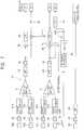
- Fig. 1is a schematic diagram of an apparatus for locating coating faults on buried pipes according to an embodiment of the invention.
- a base electric signal generator 7sends the base electric signal to buried steel pipe 11 via a power amplifier 8.
- a base electric signal line 9is attached between amplifier 8 and the buried steel pipe 11.
- the amplifier 8also is attached to ground 15.
- the base electric signalcauses a current I to run through the buried pipe 11, producing magnetic field 13.
- a leakage current 12is present due to a coating fault 14 in the buried pipe 11.
- the leakage current 12always includes orthogonal part to the current I running in the buried steel pipe. Accordingly, the magnetic field H produced by the leakage current 12 includes orthogonal part to the magnetic field 13 produced by current I running through the buried pipe.
- At least one pair of search coils 1a and 1bare provided on a movable carriage, which is located above ground.
- the search coils 1a and 1bare coupled to a differential amplifier 2.
- the differential amplifier 2is coupled to an amplifier 3, which is coupled to a detector 4.
- the detector 4receives a reference signal (REF) 10 from base electric signal generator 7.
- the output of detector 4is provided to any of various means for indicating the detected output, for example, an oscilloscope 5, etc., and to a recording means such as, for example a pen-recorder 6.
- the magnetic field H caused by the leakage current 12is converted into an induced electromotive force by the pair of search coils 1a and 1b.
- the search coils la and 1bhave respective axes, la and 1b (see Fig. 2).
- the axes of the search coilsare arranged in a direction so as to have a low sensitivity to the magnetic field (13 or 13') generated by the base electric signal running through the buried pipe.
- the search coilsare arranged in a direction so that they have a high sensitivity to the magnetic field H generated by the leakage current 12.
- the search coilshave a highest response when their axes are parallel to the direction of the magnetic field.
- the axes of the search coilsare preferably arranged so as to be parallel to the magnetic field H generated by the leakage current 12, and at least a line interconnecting the center of the axes of the search coils is not in a plane orthogonal to the axis of the buried pipe.
- the search coilsare arranged so as to have a low sensitivity to the magnetic field 13 generated by the base electric signal running in the buried pipe.
- each coil la and 1bis provided to the differential amplifier 2, the output differential of which is amplified by the amplifier 3.
- This signalis supplied to detector 4, which outputs to the oscilloscope 5 and/or the pen-recorder 6.
- This type of sensor devicewhich outputs a differential of each coil's output is referred to as differential-type search coils.
- the base electric signal transmitted from the generator 7can be sent to the buried pipe through the power amplifier 8, which is connected to ground, by, for example, an Mg electrode plate.
- the base electric signalcan be provided to the buried pipe through terminals which are usually provided at the joints of the buried pipe, for example at intervals of 100-200 meters. These terminals are accessible through, for example, a manhole.
- Fig. 1shows the minimum, single pair of search coils. While the search coils la and 1b in Fig. 1 are oriented to extend vertically, the additional pairs, for example, can extend at an angle between horizontal and vertical. It is also preferable, for example, to use a pair of coils that extend vertically and a pair of coils that are parallel to the direction of the buried pipe.
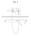
- Fig. 2illustrates the manner in which the coils are arranged relative to the buried pipe 11.
- the coils la and 1bare provided on a movable carriage (not shown in Fig. 2) that is movable in the direction of the arrow in Fig. 2.
- the search coils la and 1bare arranged so that their axes la and 1b are spaced from each other in the horizontal direction in Fig. 2.
- the search coils la and 1bare arranged so that when the carriage is moved, a straight line L drawn through the center points A and B in the longitudinal direction of the axes la and 1b of the two coils crosses a plane S normal to the axis of the buried pipe at point M.
- the use of the alternating currentfacilitates the synchronous detection technique. Moving the two coils enables one to find the gradient of the change in the magnetic field between two points along the buried steel pipe.
- the present inventiontheoretically increases the precision of the detection while removing same-phase noise by using the output differential and by orienting the coils so that they are highly sensitive only to the leakage current.
- the present arrangementalso is advantageous because it is arranged to detect the small amount of leakage current and can distinguish a temporary change in the magnetic field (i.e., a disorder in the magnetic field) created by the coating fault.
- the present inventionalso is advantageous because it uses, as REF signal 10, a signal that is related to the base electric signal provided to the buried pipe 11.
- REF signal 10a signal that is related to the base electric signal provided to the buried pipe 11.
- the present inventionrelies upon synchronous detection in which the base electric signal that is applied to the buried pipe also is applied to the differential amplifier 2 output. Using this technique, a phase deviation of the differential output relative to the base electric signal can be found and distinguished from environmental noises. That is, any phase differential of the electromotive force in the search coils changes in synchronism with any changes of the magnetic field generated by the base electric signal running through the buried pipe.
- a base electric signalhaving a frequency that is not an integer multiple of a common commercial frequency such as, 50 ⁇ 60 Hz.
- the amplifier 3the detector 4, the means for detecting the output 5, and the means for recording the output 6, along with the search coils la and 1b and the differential amplifier 2 in a mobile unit.
- the REF signal 10must be transmitted from the generator 7 to the mobile unit. This can be done via radiowaves, for example.
- a preferred radiowave transmission frequency for the base electric signalis less than or equal to 100 KHz, even more preferably between about 220 Hz and 820 Hz, in order to reduce noise.
- Fig. 3illustrates an embodiment in which the REF signal 10 is generated by a reference signal generator R provided at the search location (i.e., on the mobil unit).
- reference signal generator Rdetects the base signal from the buried pipe 11 using monitor coils 32 provided on the mobil unit.
- the manner in which the REF signal 10 is generatedis not limited to the above two examples.
- the present inventionis also advantageous, as will be described below, when it is used in combination with a GPS to output a map that identifies detected coating faults.
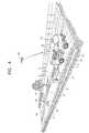
- FIG. 4illustrates one arrangement of an apparatus for locating coating faults in buried steel pipes according to an embodiment of the invention.
- a transmitter 20includes base electric signal generator 7 and power amplifier 8.
- a power supply 21provides power to transmitter 20.
- the base electric signalis output from transmitter 20 via a cable, for example, which is passed through a manhole 16 and attached to the buried pipe 11.
- a mobil unit 17includes the receiving and detecting unit 19.
- a vehicle 18such as a van includes an analyzing and indicating/recording unit 22 and a GPS unit 23.
- GPS unit 23includes a GPS antenna 24 which communicates with a satellite 25.
- the other elementsare the same as similarly referenced elements in Fig. 1.
- the transmitter 20 and power supply 21are located near a manhole 16.
- the receiving and detecting unit 19is provided in the mobil unit 17 which is pulled by vehicle 18.
- the REF signal 10is transmitted to the mobil unit 17 via radiowaves.
- GPSare well known and used as car navigation systems. GPS are capable of generating map data and are capable of indicating the present location of the GPS antenna 24. Accordingly, when coating faults are detected, this data is supplied to the GPS so that the map can mark (either on a monitor or on a printout) the location of the coating fault. Placement of GPS antenna 24 on the mobil unit 17 would further increase the accuracy of the resulting map.
- Fig. 5is a block circuit diagram of the base electric signal transmitter 20. The elements are the same as those described in Figs. 1-4.
- a REF signal transmitter 10stransmits the base electric signal via radiowaves to, for example, the mobil unit 17. In this example, a transmitting frequency of 725 Hz is used for the REF signal 10.
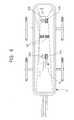
- Fig. 6is a plan view showing the position of the search coils on the mobil unit 17.
- two pairs of search coilsare provided.
- Vertical search coils 30a and 30bare vertical relative to the road surface.
- Horizontal search coils 31a and 31bare parallel to the road surface, with their axes extending parallel to the moving direction of the mobil unit 17. The coils of each pair are separated from each other by 1 meter in the moving direction of the mobil unit 17.
- Monitor coils 32which detect the base electric signal in the buried pipe, are arranged so as to be orthogonal to the search coils and located centrally between the search coils 30a, 31a and 30b, 31b.
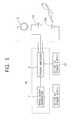
- Fig. 7is a block, circuit diagram showing the receiving and detecting unit 19.
- REF signal receiver 10Rreceives the REF signal 10 transmitted via radiowaves.
- the receiving and detecting unit 19also includes amplifiers 40, phase adjustment devices 41a, 41b, 41c and 41d, 90 degree phase-shift device 42, bandpass-filters (BPF) 43, low-pass-filters (LPF) 44, and multiplication circuits 45 in the arrangement illustrated in Fig. 7.
- Reference numerals E1-E4illustrate the detected outputs.
- the output of vertical coils 30a, 30b and ⁇ or horizontal coils 31a and 31bis sent to the differential amplifier 2 via the phase adjustment devices 41a-d so as to lose any differences in phases after passing through amplifier 40.
- the differential amplifier 2outputs the difference between the phase adjustment devices 41a and 41b and the phase adjustment devices 41c and 41d. These output differentials are output to the BPF 43, the amplifier 40, and finally synchronously detected by using the 90 degree phase-shift device 42.
- This 90 degree orthogonal synchronous detection techniqueseparates the output differential of each coil pair 30, 31. These values then are multiplied by the REF signal in the multiplication circuit 45 to provide the detected outputs El and E3 through the LPF 44.
- the other multiplication circuit 45multiplies by the REF signal 10 after it is shifted by 90 degrees by passing the REF signal 10 through the 90 degrees phase-shift device 42, to produce the detected outputs E2 and E4 through the LPF 44.
- the outputs El and E2 of the vertical search coils (30a and 30b)are plotted along the x axis and y axis, respectively, while the outputs E3 and E4 of the horizontal coils (31a and 31b) are plotted along the x axis and the y axis, respectively. This enables the magnitude and phase of each paired coil output differential to be displayed.
- the detected output coating faulthas a phase-shift.
- the present inventioncan simultaneously estimate the magnitude and phase of each coil pair output differential, the location of coating faults can be found with a higher precision than in previous devices that only roughly detected the magnitude of the magnetic field.
- monitor coils 32when monitor coils 32 are included, the monitor coil output is amplified by amplifier 40, sent through the BPF 43 and output as the monitor coil output.
- Fig. 9is a block circuit diagram showing the analyzing and indicating ⁇ recording unit and the GPS unit.
- the analyzing unitincludes an A ⁇ D and D ⁇ A (analog-to-digital and digital-to-analog converter), a CPU (central processing unit) and a VDT (Video Display Terminal).
- An interfacecouples the analyzing part with the indicating ⁇ recording part and the GPS.
- the detected outputs E1-E4 from the receiving and detecting unit 19 and the monitor coil output 32is provided to the A ⁇ D and D ⁇ A converter as analog signals. These are converted to digital signals.
- the CPUprocesses the data and provides it to the indicating means (e.g., the oscilloscope) and ⁇ or to the recording means (e.g., the pen-recorder).
- the CPUalso can combine the data representing locations of coating faults with map data provided by the GPS via the VDT so as to indicate the location of coating faults on a map.
- Fig. 10illustrates the output of a pen-recorder based upon data E1-E4. As can be seen by Fig. 10, the location of coating faults are easily detected based upon a disruption in the output.
- Fig. 11illustrates a map generated by the GPS and identifying coating faults thereon. There are two coating faults identified on this map. This enables the searching operation to become more efficient because the data relating to locations of coating faults are quickly processed and output on a map.
- the present inventionprovides a higher precision apparatus and method for locating coating faults on buried pipelines than possible with previous methods. This is achieved by detecting local disorders of a magnetic field generated by leakage current from coating faults. As described above, the local disorder is detected by at least one pair of search coils. Additionally, a 90-degree orthogonal synchronization technique is used to detect an output differential of the search coils while using a base electric signal that is transmitted to the buried pipe as a reference signal. The system simultaneously estimates the magnitude and phase of each pair of coil output differential and is able to detect only the magnetic field generated from the leakage current, without being interfered with by environmental noise.
- map datais readily generated that identifies locations of the coating faults.
Landscapes
- Chemical & Material Sciences (AREA)
- Life Sciences & Earth Sciences (AREA)
- Immunology (AREA)
- General Health & Medical Sciences (AREA)
- Pathology (AREA)
- Physics & Mathematics (AREA)
- Health & Medical Sciences (AREA)
- General Physics & Mathematics (AREA)
- Analytical Chemistry (AREA)
- Biochemistry (AREA)
- Ecology (AREA)
- Environmental & Geological Engineering (AREA)
- Biodiversity & Conservation Biology (AREA)
- Environmental Sciences (AREA)
- Chemical Kinetics & Catalysis (AREA)
- Electrochemistry (AREA)
- Investigating Or Analyzing Materials By The Use Of Magnetic Means (AREA)
- Geophysics And Detection Of Objects (AREA)
- Measuring Magnetic Variables (AREA)
Abstract
Description
The present invention relates to methods and apparatus for locatingcoating faults on buried pipelines, and in particular to such methods and apparatusthat rely upon magnetic field detection.
Many steps are taken to prevent buried metal pipe (e.g., steel pipe)from being subjected to corrosion by, for example, electro-chemical reactions. Forexample, it is known to coat the surface of the steel pipe with a material and/or tokeep the pipe's electric potential equal or lower to that of the ground.
In many instances, it is necessary to regularly check the condition ofthe pipe after it is buried to determine whether any corrosion of the pipe has takenplace. This is particularly important when the buried pipe is, for example, a gaspipeline.
Accordingly, it is known to check the condition of buried gas pipelinesfrom above the ground using electromagnetic searching techniques. Using suchtechniques, the location of coating faults in the pipeline or the location where thepipeline touches another buried pipe, for example a water pipe, can be detected.
The publication entitled The 30th Automatic Control Annual Meeting(4044, pages 745-746, October 1987) describes a searching system that combinessoil-to-soil potential methods with magnetic field measuring methods to locatecoating faults. In particular, a magnetic field change that is generated due to acoating fault in a buried pipeline to which a base electric signal is applied isdetected in order to locate the coating faults. This technique is prone to difficultiesand mistakes because the soil-to-soil potential method requires that an electricsignal is run from the road surface.
Japanese Laid-Open Patent Application No. 3-152411 discloses atechnique that locates coating faults using only magnetic methods. However, withthis arrangement, it is difficult to locate the origin of leakage current (from coating faults) because the magnetic field generated by the leakage current is weak and thedisclosed method is strongly influenced from environmental noise.
Additionally, these techniques involve processing and recording the databy hand, which requires much time and complicated work.
It is an object of the present invention to overcome the shortcomingsdiscussed above.
It is another object of the present invention to provide methods andapparatus for locating coating faults on buried metal pipes with a higher precisionand more convenient operation than in previous techniques.
In order to achieve the above and other objects, a coating fault locatingtechnique according to the invention transmits a base electric signal from a powersource to the buried metal pipe. A location of a coating fault in the buried pipe isdetected by detecting a gradient of a changing magnetic field between two pointsspaced along the buried pipe. The gradient is detected based upon the outputdifferential of at least one pair of search coils. The gradient is caused by a leakageof current that occurs at the coating fault.
In particular, the at least one pair of search coils are provided in amobile unit that is located above ground. The at least one pair of search coils arespaced apart from one another and have their axes arranged so as to have a lowsensitivity to a magnetic field generated by the base electric signal running throughthe buried pipe. The at least one pair of coils are spaced apart from each othersuch that a line drawn between midpoints of the search coils' axes crosses a planenormal to the axis of the buried pipe.
For example, the at least one pair of search coils are spaced from eachother horizontally, with each coil arranged with its axis extending in a verticalplane.
According to a preferred embodiment, data detected by the search coilsin the mobile unit is transmitted to a GPS system, which then generates a mapidentifying the locations of any detected coating faults.
An apparatus according to the invention includes structure to performthe method detailed above. According to one embodiment, the apparatus includes a base electric signal generator that generates a base electric signal in a buried pipe.The apparatus also includes a movable carriage on which at least one pair of searchcoils are mounted. The movable carriage is movable in a direction along theburied pipe. The at least one pair of search coils are spaced from each other todetect a gradient of a magnetic field along a length of the buried pipe.
A detector unit synchronously detects an output differential of the atleast one pair of search coils based upon a reference signal. The reference signalcan be the base electric signal, which is transmitted to the buried pipe and to thedetector unit. Alternatively, the detector unit can receive the reference signal bydetecting the base electric signal in the buried pipe. For example, the movablecarriage can include monitor coils that electromagnetically detect the base electricsignal in the buried pipe. As another alternative, the base electric signal can beprovided to the detector unit from the base electric signal generator via either ahard-wired coupling or via radiowaves.
The detector unit can transmit data relating to detected coating faults toa Global Positioning System (GPS), which then transmits data to a monitor orprinting device, to generate a map indicating locations of the coating faults.
The invention will be described in detail with reference to the followingdrawings in which like reference numerals refer to like elements and wherein:
According to the present invention, a base electric signal generatorapplies a base electric signal to buried metal pipe, such as, for example a buriedsteel gas pipeline. The base electric signal applied to the buried steel pipe resultsin a magnetic field being generated from the buried steel pipe. Any coating faultsin the buried pipe, which can lead to (or be caused by) corrosion of the pipe, resultin current (known as leakage current) leaking from the buried steel pipe. Thisleakage current creates a magnetic field part orthogonal to the magnetic fieldgenerated from the buried pipe.
According to the invention, at least one pair of search coils providedabove ground, for example in a movable carriage, detect this orthogonal magneticfield part caused by the leakage current. In particular, the at least one pair ofsearch coils are spaced apart from each other, for example, along the length of theburied pipe. The axes of the search coils are oriented so that they are sensitive tomagnetic fields in the orthogonal direction (i.e., magnetic fields due to the leakagecurrent) of the pipe. A detector unit receives outputs from the search coils and,using a reference signal, which is based on the base electric signal, detects theorthogonal magnetic field. In particular, the detector uses 90 degree orthogonalsynchronous detection.
The reference signal can be directly supplied to the detector unit by thebase electric signal generator. This can be a hard-wire transmission or a radiowavetransmission. Alternatively, the reference signal can be supplied by detecting the base electric signal in the buried steel pipe. For example, the movable carriage caninclude appropriately arranged monitor coils that detect the base electric signal inthe buried steel pipe. As another alternative, an additional electric signal generatorthat generates the reference signal having the same frequency as that of the baseelectric signal generated by the base electric signal generator can be provided, forexample, at the search location. In this case, prior to detection, the additionalgenerator and thebase generator 7 are synchronized.
Furthermore, it is preferable to provide a Global Positioning System(GPS) that receives data relating to the location of detected coating faults. TheGPS then generates a map (either on a monitor or on paper) that identifies thecoating faults.
Fig. 1 is a schematic diagram of an apparatus for locating coating faultson buried pipes according to an embodiment of the invention. A baseelectricsignal generator 7 sends the base electric signal to buriedsteel pipe 11 via apoweramplifier 8. In particular, a baseelectric signal line 9 is attached betweenamplifier 8 and the buriedsteel pipe 11. Theamplifier 8 also is attached toground 15. Thebase electric signal causes a current I to run through the buriedpipe 11, producingmagnetic field 13.
A leakage current 12 is present due to acoating fault 14 in the buriedpipe 11. The leakage current 12 always includes orthogonal part to the current Irunning in the buried steel pipe. Accordingly, the magnetic field H produced bythe leakage current 12 includes orthogonal part to themagnetic field 13 producedby current I running through the buried pipe.
Due to leakage current 12, the current I' and its accompanying magneticfield 13' downstream of thecoating fault 14 is less than the current I andmagneticfield 13 upstream of thecoating fault 14. Roughly speaking, I=I'+12.
At least one pair ofsearch coils search coils differential amplifier 2. Thedifferential amplifier 2 is coupled to anamplifier 3,which is coupled to adetector 4. Thedetector 4 receives a reference signal (REF)10 from baseelectric signal generator 7. The output ofdetector 4 is provided toany of various means for indicating the detected output, for example, anoscilloscope 5, etc., and to a recording means such as, for example a pen-recorder 6.
The magnetic field H caused by the leakage current 12 is converted intoan induced electromotive force by the pair ofsearch coils
In particular, the search coils have a highest response when their axesare parallel to the direction of the magnetic field. Accordingly, the axes of thesearch coils are preferably arranged so as to be parallel to the magnetic field Hgenerated by the leakage current 12, and at least a line interconnecting the center ofthe axes of the search coils is not in a plane orthogonal to the axis of the buriedpipe. Accordingly, the search coils are arranged so as to have a low sensitivity tothemagnetic field 13 generated by the base electric signal running in the buriedpipe.
The output of each coil la and 1b is provided to thedifferentialamplifier 2, the output differential of which is amplified by theamplifier 3. Thissignal is supplied todetector 4, which outputs to theoscilloscope 5 and/or the pen-recorder 6. This type of sensor device, which outputs a differential of each coil'soutput is referred to as differential-type search coils.
The base electric signal transmitted from thegenerator 7 can be sent tothe buried pipe through thepower amplifier 8, which is connected to ground, by,for example, an Mg electrode plate. The base electric signal can be provided to theburied pipe through terminals which are usually provided at the joints of the buriedpipe, for example at intervals of 100-200 meters. These terminals are accessiblethrough, for example, a manhole.
The direction of the magnetic flux in the magnetic field H generated bythe leakage current 12 is not constant because the direction of the current canchange. Accordingly, it is preferable to provide more than one pair of search coils,with each pair extending in different directions. Thus, Fig. 1 shows the minimum, single pair of search coils. While the search coils la and 1b in Fig. 1 are orientedto extend vertically, the additional pairs, for example, can extend at an anglebetween horizontal and vertical. It is also preferable, for example, to use a pair ofcoils that extend vertically and a pair of coils that are parallel to the direction ofthe buried pipe.
Fig. 2 illustrates the manner in which the coils are arranged relative tothe buriedpipe 11. The coils la and 1b are provided on a movable carriage (notshown in Fig. 2) that is movable in the direction of the arrow in Fig. 2. Thesearch coils la and 1b are arranged so that their axes la and 1b are spaced fromeach other in the horizontal direction in Fig. 2. The search coils la and 1b arearranged so that when the carriage is moved, a straight line L drawn through thecenter points A and B in the longitudinal direction of the axes la and 1b of the twocoils crosses a plane S normal to the axis of the buried pipe at point M.
The use of the alternating current facilitates the synchronous detectiontechnique. Moving the two coils enables one to find the gradient of the change inthe magnetic field between two points along the buried steel pipe.
In this case, if there are no coating faults, the magnetic field generatedby the current caused by the base electrical signal is almost constant. Accordingly,there is virtually no differential of the induced electromotive force in the searchcoils. However, when there is a coating fault, a disorder of a magnetic field locallygenerated by the leakage current exists; and is detected because the differential ofthe electromotive force in the search coils changes. As the pair of search coils laand 1b are arranged in the same direction and are maintained at a constant interval,the detection of the gradient of the change in magnetic field between this intervalcan be found. With prior magnetic field-detecting methods, it was difficult todetect a small change in the magnetic field because only absolute values wereconsidered.
However, the present invention theoretically increases the precision ofthe detection while removing same-phase noise by using the output differential andby orienting the coils so that they are highly sensitive only to the leakage current.The present arrangement also is advantageous because it is arranged to detect the small amount of leakage current and can distinguish a temporary change in themagnetic field (i.e., a disorder in the magnetic field) created by the coating fault.
The present invention also is advantageous because it uses, asREFsignal 10, a signal that is related to the base electric signal provided to the buriedpipe 11. In prior systems using a reference signal that is not related to the baseelectric signal applied to the buried pipe, there were many difficulties and mistakesmade due to the difficulty in distinguishing the magnetic field created by the baseelectric signal and magnetic fields created from external sources, for example,environmental noise in the 50\60 Hz range.
The present invention relies upon synchronous detection in which thebase electric signal that is applied to the buried pipe also is applied to thedifferential amplifier 2 output. Using this technique, a phase deviation of thedifferential output relative to the base electric signal can be found and distinguishedfrom environmental noises. That is, any phase differential of the electromotiveforce in the search coils changes in synchronism with any changes of the magneticfield generated by the base electric signal running through the buried pipe.
It is preferable to use a base electric signal having a frequency that isnot an integer multiple of a common commercial frequency such as, 50\60 Hz.
With respect to the coating fault location operation, from the viewpointof working efficiency, it would be better to provide theamplifier 3, thedetector 4,the means for detecting theoutput 5, and the means for recording theoutput 6,along with the search coils la and 1b and thedifferential amplifier 2 in a mobileunit. With such an arrangement, theREF signal 10 must be transmitted from thegenerator 7 to the mobile unit. This can be done via radiowaves, for example.
A preferred radiowave transmission frequency for the base electricsignal is less than or equal to 100 KHz, even more preferably between about 220Hz and 820 Hz, in order to reduce noise.
Fig. 3 illustrates an embodiment in which theREF signal 10 isgenerated by a reference signal generator R provided at the search location (i.e., onthe mobil unit). In this embodiment, reference signal generator R detects the basesignal from the buriedpipe 11 using monitor coils 32 provided on the mobil unit. However, the manner in which theREF signal 10 is generated is not limited to theabove two examples.
The present invention is also advantageous, as will be described below,when it is used in combination with a GPS to output a map that identifies detectedcoating faults.
Fig. 4 illustrates one arrangement of an apparatus for locating coatingfaults in buried steel pipes according to an embodiment of the invention. Atransmitter 20 includes baseelectric signal generator 7 andpower amplifier 8. Apower supply 21 provides power totransmitter 20. The base electric signal isoutput fromtransmitter 20 via a cable, for example, which is passed through amanhole 16 and attached to the buriedpipe 11. Amobil unit 17 includes thereceiving and detectingunit 19. Avehicle 18 such as a van includes an analyzingand indicating/recording unit 22 and aGPS unit 23.GPS unit 23 includes aGPSantenna 24 which communicates with asatellite 25. The other elements are thesame as similarly referenced elements in Fig. 1.
As shown in Fig. 4, thetransmitter 20 andpower supply 21 are locatednear amanhole 16. The receiving and detectingunit 19 is provided in themobilunit 17 which is pulled byvehicle 18. TheREF signal 10 is transmitted to themobil unit 17 via radiowaves.
Recently, GPS are well known and used as car navigation systems.GPS are capable of generating map data and are capable of indicating the presentlocation of theGPS antenna 24. Accordingly, when coating faults are detected,this data is supplied to the GPS so that the map can mark (either on a monitor oron a printout) the location of the coating fault. Placement ofGPS antenna 24 onthemobil unit 17 would further increase the accuracy of the resulting map.
Fig. 5 is a block circuit diagram of the baseelectric signal transmitter 20. The elements are the same as those described in Figs. 1-4. AREF signaltransmitter 10s transmits the base electric signal via radiowaves to, for example, themobil unit 17. In this example, a transmitting frequency of 725 Hz is used for theREF signal 10.
Fig. 6 is a plan view showing the position of the search coils on themobil unit 17. In this embodiment, two pairs of search coils are provided.Vertical search coils Horizontal search coils mobil unit 17. The coils of eachpair are separated from each other by 1 meter in the moving direction of themobilunit 17. Monitor coils 32, which detect the base electric signal in the buried pipe,are arranged so as to be orthogonal to the search coils and located centrallybetween thesearch coils
Fig. 7 is a block, circuit diagram showing the receiving and detectingunit 19.REF signal receiver 10R receives theREF signal 10 transmitted viaradiowaves. The receiving and detectingunit 19 also includesamplifiers 40,phaseadjustment devices shift device 42, bandpass-filters(BPF) 43, low-pass-filters (LPF) 44, andmultiplication circuits 45 inthe arrangement illustrated in Fig. 7. Reference numerals E1-E4 illustrate thedetected outputs.
The output ofvertical coils horizontal coils differential amplifier 2 via thephase adjustment devices 41a-d soas to lose any differences in phases after passing throughamplifier 40. Thedifferential amplifier 2 outputs the difference between thephase adjustment devices phase adjustment devices BPF 43, theamplifier 40, and finally synchronouslydetected by using the 90 degree phase-shift device 42.
This 90 degree orthogonal synchronous detection technique separatesthe output differential of each coil pair 30, 31. These values then are multiplied bythe REF signal in themultiplication circuit 45 to provide the detected outputs Eland E3 through theLPF 44. Theother multiplication circuit 45 multiplies by theREF signal 10 after it is shifted by 90 degrees by passing theREF signal 10through the 90 degrees phase-shift device 42, to produce the detected outputs E2and E4 through theLPF 44.
As shown in Fig. 8, the outputs El and E2 of the vertical search coils(30a and 30b) are plotted along the x axis and y axis, respectively, while the outputs E3 and E4 of the horizontal coils (31a and 31b) are plotted along the x axisand the y axis, respectively. This enables the magnitude and phase of each pairedcoil output differential to be displayed.
In many tests conducted by the inventors, it is clear that the detectedoutput coating fault has a phase-shift. As the present invention can simultaneouslyestimate the magnitude and phase of each coil pair output differential, the locationof coating faults can be found with a higher precision than in previous devices thatonly roughly detected the magnitude of the magnetic field.
As further shown in Fig. 7, when monitor coils 32 are included, themonitor coil output is amplified byamplifier 40, sent through theBPF 43 andoutput as the monitor coil output.
Fig. 9 is a block circuit diagram showing the analyzing andindicating\recording unit and the GPS unit. The analyzing unit includes an A\Dand D\A (analog-to-digital and digital-to-analog converter), a CPU (centralprocessing unit) and a VDT (Video Display Terminal). An interface couples theanalyzing part with the indicating\recording part and the GPS.
The detected outputs E1-E4 from the receiving and detectingunit 19and themonitor coil output 32 is provided to the A\D and D\A converter as analogsignals. These are converted to digital signals. The CPU processes the data andprovides it to the indicating means (e.g., the oscilloscope) and\or to the recordingmeans (e.g., the pen-recorder). The CPU also can combine the data representinglocations of coating faults with map data provided by the GPS via the VDT so asto indicate the location of coating faults on a map.
Fig. 10 illustrates the output of a pen-recorder based upon data E1-E4.As can be seen by Fig. 10, the location of coating faults are easily detected basedupon a disruption in the output.
Fig. 11 illustrates a map generated by the GPS and identifying coatingfaults thereon. There are two coating faults identified on this map. This enablesthe searching operation to become more efficient because the data relating tolocations of coating faults are quickly processed and output on a map.
The present invention provides a higher precision apparatus and methodfor locating coating faults on buried pipelines than possible with previous methods. This is achieved by detecting local disorders of a magnetic field generated byleakage current from coating faults. As described above, the local disorder isdetected by at least one pair of search coils. Additionally, a 90-degree orthogonalsynchronization technique is used to detect an output differential of the search coilswhile using a base electric signal that is transmitted to the buried pipe as areference signal. The system simultaneously estimates the magnitude and phase ofeach pair of coil output differential and is able to detect only the magnetic fieldgenerated from the leakage current, without being interfered with by environmentalnoise.
Additionally, by transmitting data via radiowaves to a GPS, map data isreadily generated that identifies locations of the coating faults.
While this invention has been described in conjunction with specificembodiments thereof, it is evident that many alternatives, modifications andvariations will be apparent to those skilled in the art. Accordingly, the preferredembodiments of the invention set forth herein are intended to be illustrative, notlimiting. Various changes may be made without departing from the spirit andscope of the invention as defined in the following claims.
Claims (24)
- A method of locating coating faults on a buried pipe, comprising thesteps of:transmitting a base electric signal from a source to the buried pipe;anddetecting a location of coating faults on the buried pipe by detectinga gradient of a changing magnetic field between two points along the buried pipecaused by a leakage of current from the coating faults based upon an outputdifferential of at least one pair of search coils.
- The method of claim 1, wherein the detecting step includes:arranging each coil of the at least one pair of search coils so that theaxes of the search coils are spaced from each other by a distance in a directionsuch that a line interconnecting the axes of the search coils crosses a planeorthogonal to an axis of the buried pipe, the axes being arranged so as to have alow sensitivity to a magnetic field generated by the base electric signal running inthe buried pipe;moving the at least one pair of search coils along a direction of theburied pipe; andfinding a disorder of a magnetic field generated by the leakagecurrent from the coating fault in the buried pipe by finding an output differential ofthe at least one pair of search coils, wherein the base electric signal is used as areference signal to synchronously detect the output differential of the at least onepair of search coils.
- The method of claim 2, wherein the reference signal is transmittedfrom the source via radiowaves to a unit that synchronously detects the outputdifferential of the search coils.
- The method of claim 2, wherein the reference signal is generated ata location of the search coils by detecting the base electric signal running in theburied pipe using monitor coils.
- The method of claim 2, wherein the reference signal is generated byan additional electric signal generator that generates the reference signal to have asame frequency as the base electric signal.
- The method of claim 2, wherein the synchronous detecting uses a 90degree phase difference between outputs of the search coils.
- The method of claim 1, further comprising the step of identifyinglocations of the coating faults on a map using a Global Positioning System.
- An apparatus for locating coating faults on a buried pipe,comprising:a movable carriage, at least one pair of search coils mounted on themovable carriage, the at least one pair of search coils spaced from each other in amoving direction of the movable carriage; anda base electric signal generator that applies a base electric signal to aburied pipe, wherein the at least one pair of search coils detects a gradient of amagnetic field resulting from leakage of current through coating faults in the buriedpipe.
- The apparatus of claim 8, further comprising a pair of monitor coilsmounted on the movable carriage to detect the base electric signal in the buriedpipe.
- The apparatus of claim 8, wherein axes of the at least one pair ofcoils are oriented so as to have a low sensitivity to a magnetic field generated bythe base electric signal running in the buried pipe.
- The apparatus of claim 8, further comprising:
a detector coupled to the at least one pair of search coils, thedetector executing synchronous detection of an output differential of the at leastone pair of search coils by using a reference signal that is based on the baseelectric signal. - The apparatus of claim 11, wherein the base electric signal generatorincludes a radiowave emitter, the detector includes a radiowave receiver, and thebase electric signal is transmitted from the base electric signal generator to thedetector by radiowaves.
- The apparatus of claim 11, wherein the detector includes a pair ofmonitor coils that detect the base electric signal running in the buried pipe, thereference signal being based upon the detected base electric signal.
- The apparatus of claim 11, wherein the detector includes anadditional electric signal generator that generates the reference signal so as to havea same frequency as the base electric signal.
- The apparatus of claim 8, further comprising means for visuallyindicating outputs of the at least one pair of search coils.
- The apparatus of claim 15, wherein the means for visually indicatingincludes an oscilloscope.
- The apparatus of claim 15, wherein the means for visually indicatingincludes a pen recorder.
- The apparatus of claim 15, wherein the means for visually indicatinggenerates a map on which the detected coating faults are identified.
- The apparatus of claim 8, further comprising a Global PositioningSystem coupled to the at least one pair of search coils to generate a map on whichthe coating faults are identified.
- A method of locating coating faults on a buried pipe, comprising thesteps of:supplying a base electric signal from a source to the buried pipe;moving a movable carriage above ground in a vicinity of the buriedpipe, the movable carriage including at least one pair of search coils that are spacedfrom each other in a movement direction of the movable carriage; anddetecting a location of coating faults on the buried pipe based oncurrents induced in the at least one pair of search coils by a changing magneticfield caused by a leakage of current, caused by the supplied base electric signal,from the coating faults.
- The method of claim 20, wherein:each search coil of the at least one pair of search coils is arranged onthe movable carriage so that axes of the search coils are spaced from each other bya distance in a direction such that a line interconnecting the axes of the search coilscrosses a plane orthogonal to an axis of the buried pipe, the axes being arranged soas to have a low sensitivity to a magnetic field generated by the base electric signalrunning in the buried pipe;the moving step includes moving the at least one pair of search coilsalong a direction of the buried pipe; andthe detecting step includes finding a disorder of a magnetic fieldgenerated by the leakage current from the coating fault in the buried pipe byfinding an output differential of the at least one pair of search coils, wherein thebase electric signal is used as a reference signal to synchronously detect the outputdifferential of the at least one pair of search coils.
- The method of claim 20, further comprising the step of identifyinglocations of the coating faults on a map using a Global Positioning System.
- A method of locating coating faults on a buried pipe, comprising thesteps of:detecting at least one coating fault on a buried pipe by moving amovable carriage containing a coating fault detector above ground in the vicinity ofthe buried pipe;transmitting position data of a position where the at least one coatingfault was located to a Global Positioning System; andgenerating a map that indicates the position of the at least onecoating fault using data from the Global Positioning System.
- An apparatus for locating coating faults on a buried pipe,comprising:a movable carriage containing a coating fault detector, the movablecarriage being movable above ground in the vicinity of the buried pipe to detectcoating faults in buried pipe;means for transmitting position data of a position where the at leastone coating fault was located to a Global Positioning System; andmeans for generating a map that indicates the position of the at leastone coating fault using data from the Global Positioning System.
Applications Claiming Priority (3)
| Application Number | Priority Date | Filing Date | Title |
|---|---|---|---|
| JP9009615AJPH10206390A (en) | 1997-01-22 | 1997-01-22 | Method for detecting damage to buried steel pipe coating |
| JP9615/97 | 1997-01-22 | ||
| JP961597 | 1997-01-22 |
Publications (2)
| Publication Number | Publication Date |
|---|---|
| EP0855595A2true EP0855595A2 (en) | 1998-07-29 |
| EP0855595A3 EP0855595A3 (en) | 2000-07-26 |
Family
ID=11725207
Family Applications (1)
| Application Number | Title | Priority Date | Filing Date |
|---|---|---|---|
| EP98300421AWithdrawnEP0855595A3 (en) | 1997-01-22 | 1998-01-21 | Method and apparatus for locating coating faults on buried pipeline |
Country Status (3)
| Country | Link |
|---|---|
| US (1) | US6051977A (en) |
| EP (1) | EP0855595A3 (en) |
| JP (1) | JPH10206390A (en) |
Cited By (10)
| Publication number | Priority date | Publication date | Assignee | Title |
|---|---|---|---|---|
| EP0989353A3 (en)* | 1998-09-23 | 2001-08-16 | Pipeline Integrity International, Inc. | Mapping system for the integration and graphical display of pipeline information that enables automated pipeline surveillance |
| WO2005080934A1 (en)* | 2004-02-12 | 2005-09-01 | Dynalog Electronics Ltd | Surveying of buried pipelines |
| WO2005091020A1 (en) | 2004-03-17 | 2005-09-29 | 3M Innovative Properties Company | Gps interface for locating device |
| WO2007017685A3 (en)* | 2005-08-09 | 2007-03-29 | Tuscan Corrosion Control Ltd | Pipe evaluation apparatus and method |
| EP2172158A1 (en) | 1999-10-01 | 2010-04-07 | United States Surgical Corporation | Anastomosis instrument and method for performing same |
| CN102954754A (en)* | 2011-08-19 | 2013-03-06 | 丹阳奥恩能源科技发展有限公司 | Detection method for equivalent diameter of anticorrosive coating damaged surface of buried steel pipeline |
| RU2504763C1 (en)* | 2012-09-12 | 2014-01-20 | Общество с ограниченной ответственностью "Диагностические системы" (Company Limited "DIAS") | Method and device for diagnostics of technical state of underground pipelines |
| RU2510500C1 (en)* | 2012-09-12 | 2014-03-27 | Общество с ограниченной ответственностью "Диагностические системы" (Company Limited "DIAS") | Method and device for diagnostics of buried pipeline |
| CN105699481A (en)* | 2016-03-18 | 2016-06-22 | 中国计量学院 | A device for detecting micro-cracks near the surface of pressure-bearing equipment |
| CN107975680A (en)* | 2017-11-28 | 2018-05-01 | 厦门市特种设备检验检测院 | A kind of buried pipeline PCM detectors positive signal loading device |
Families Citing this family (31)
| Publication number | Priority date | Publication date | Assignee | Title |
|---|---|---|---|---|
| GB0013620D0 (en) | 2000-06-06 | 2000-07-26 | Howell Mark I | A technique for finding the position and depth of any buried pipeline or cable accurately, even where it may be lying close to other long buried conductors |
| RU2187100C2 (en)* | 2000-06-30 | 2002-08-10 | Общество с ограниченной ответственностью "Научно-исследовательский институт природных газов и газовых технологий - ВНИИГАЗ" | Magnetic introscope for monitoring pipe line without breaking soil |
| US6529006B1 (en)* | 2001-10-31 | 2003-03-04 | Paul Hayes | Method and apparatus for resolving the position and identity of buried conductive bodies |
| US6650125B1 (en) | 2001-12-06 | 2003-11-18 | The United States Of America As Represented By The Administrator Of The National Aeronautics And Space Administration | Leak and pipe detection method and system |
| US7642790B2 (en)* | 2003-05-06 | 2010-01-05 | Profile Technologies, Inc. | Systems and methods for testing conductive members employing electromagnetic back scattering |
| JP3746283B2 (en)* | 2003-09-22 | 2006-02-15 | エヌ・ティ・ティ・インフラネット株式会社 | Continuous cable position search device, continuous cable position search method, and continuous cable position search program |
| JP4029118B2 (en)* | 2003-10-28 | 2008-01-09 | 新日鉄エンジニアリング株式会社 | Method for detecting metal touch part of buried metal pipe |
| JP2005351626A (en)* | 2004-06-08 | 2005-12-22 | Shikoku Res Inst Inc | Nondestructive inspection method and its device |
| MXNL04000086A (en)* | 2004-11-04 | 2006-05-09 | Geo Estratos S A De C V | Method for locating leakages in non-metallic underground pipes. |
| US7317308B2 (en)* | 2005-01-27 | 2008-01-08 | Shell Oil Company | System and method for measuring electric current in a pipeline |
| US7821247B2 (en)* | 2005-01-27 | 2010-10-26 | Shell Oil Company | System and method for measuring electric current in a pipeline |
| RU2379673C1 (en)* | 2008-07-21 | 2010-01-20 | Открытое акционерное общество (ОАО) "Гипрогазцентр" | Device contactless measurement of cathode protection current |
| US7880484B2 (en)* | 2008-11-10 | 2011-02-01 | Saudi Arabian Oil Company | Method and apparatus for estimating the condition of a coating on an underground pipeline |
| US8000936B2 (en)* | 2008-11-10 | 2011-08-16 | Saudi Arabian Oil Company | Data analysis system for determining coating conditions of a buried pipeline |
| US7876110B2 (en)* | 2008-11-10 | 2011-01-25 | Saudi Arabian Oil Company | Method and apparatus for simulating electrical characteristics of a coated segment of a pipeline |
| RU2400779C1 (en)* | 2009-02-05 | 2010-09-27 | Общество с ограниченной ответственностью "Парсек", ООО "ПАРСЕК" | Method of searching for damages in underground pipe insulation |
| US9207192B1 (en) | 2009-03-19 | 2015-12-08 | Wavetrue, Inc. | Monitoring dielectric fill in a cased pipeline |
| US8555722B2 (en)* | 2009-09-17 | 2013-10-15 | Gas Technology Institute | Method and apparatus for underground line crossing detection |
| GB201203717D0 (en)* | 2012-03-02 | 2012-04-18 | Speir Hunter Ltd | Fault detection for pipelines |
| WO2015041906A1 (en)* | 2013-09-18 | 2015-03-26 | 3M Innovative Properties Company | Underground data communication apparatus, system, and method |
| EP3418756B1 (en)* | 2013-11-19 | 2025-04-23 | Hyun Chang Lee | Mobile electric leakage detection device and method |
| MX344113B (en) | 2014-01-24 | 2016-10-25 | Inst Mexicano Del Petróleo | High powered current generator for electromagnetic inspection of hydrocarbon pipelines. |
| US9961418B2 (en) | 2014-06-20 | 2018-05-01 | 3M Innovative Properties Company | Data communication appratus, system, and method |
| CN105403618B (en)* | 2015-06-12 | 2018-09-18 | 宁波市鄞州磁泰电子科技有限公司 | Buried pipeline defect magnetic method detection method |
| KR101739705B1 (en)* | 2016-09-27 | 2017-05-26 | 공영상 | Multi test apparatus for buried gas pipelines and multi test method using the same |
| CN106970143A (en)* | 2017-04-20 | 2017-07-21 | 武汉地大华睿地学技术有限公司 | A kind of method that contactless double source magnetic field comprehensive detects metallic conduit defect |
| CN108562639B (en)* | 2018-01-12 | 2022-02-25 | 西南石油大学 | A method for external detection of defects in the whole life cycle of buried steel pipelines |
| CN108254434B (en)* | 2018-02-11 | 2022-02-01 | 广东省特种设备检测研究院顺德检测院 | Buried pipeline excavation-free magnetic induction detection probe array device and detection method |
| CN109632940B (en)* | 2018-11-20 | 2020-02-28 | 西南石油大学 | Non-contact identification and positioning method for circumferential weld of pipeline in mountainous region |
| KR102765644B1 (en)* | 2020-07-20 | 2025-02-11 | 주식회사 엘지에너지솔루션 | Apparatus for detecting crack of electrode plate |
| CN114383998B (en)* | 2021-12-28 | 2024-09-06 | 国家管网集团川气东送天然气管道有限公司 | Pipeline corrosion monitoring method, system and electronic equipment |
Family Cites Families (20)
| Publication number | Priority date | Publication date | Assignee | Title |
|---|---|---|---|---|
| US3745452A (en)* | 1971-02-23 | 1973-07-10 | J Osburn | Magnetic field gradient apparatus and method for detecting pipe line corrosion |
| US4134061A (en)* | 1977-02-02 | 1979-01-09 | Gudgel Howard S | Pipe current detector with plural magnetic flux detectors |
| JPS5422890A (en)* | 1977-07-20 | 1979-02-21 | Sumitomo Chem Co Ltd | Location of damage of corrosion preventive coating film of steel pipe laid on water bottom |
| US4390836A (en)* | 1980-08-11 | 1983-06-28 | Marathon Oil Company | Method and apparatus for the detection of pipeline holidays |
| JPS61210935A (en)* | 1985-03-15 | 1986-09-19 | Nippon Steel Corp | Method for detecting corroded, coated and damaged position of buried metallic tube |
| JPS6279347A (en)* | 1985-10-02 | 1987-04-11 | Osaka Gas Co Ltd | Detection of hidden conductor |
| JPS62113058A (en)* | 1985-11-13 | 1987-05-23 | Nippon Kokan Kk <Nkk> | Method for detecting paint film damage on coated steel pipes |
| JP2526578B2 (en)* | 1986-06-26 | 1996-08-21 | 日本鋼管株式会社 | Coating film damage detection method |
| FI863487A7 (en)* | 1986-08-27 | 1988-02-28 | Matti Viikari | A method and device based on electromagnetic induction for monitoring the condition of the electrical insulation of conductors in a conductive medium. |
| JPS6378063A (en)* | 1986-09-20 | 1988-04-08 | Osaka Gas Co Ltd | Damage detecting method for body buried underground |
| US4839593A (en)* | 1987-12-17 | 1989-06-13 | Atlantic Richfield Company | Transient electromagnetic method for directly detecting corrosion on conductive containers |
| JPH0230050U (en)* | 1988-08-19 | 1990-02-26 | ||
| US5126654A (en)* | 1989-02-10 | 1992-06-30 | New York Gas Group | Non-invasive, high resolution detection of electrical currents and electrochemical impedances at spaced localities along a pipeline |
| JPH0326981A (en)* | 1989-06-23 | 1991-02-05 | Tokyo Gas Co Ltd | Apparatus for detecting ground embedded pipe |
| JPH0326983A (en)* | 1989-06-23 | 1991-02-05 | Tokyo Gas Co Ltd | Method and apparatus for detecting position of ground embedded pipe |
| JPH03152411A (en)* | 1989-11-09 | 1991-06-28 | Japan Steel & Tube Constr Co Ltd | Detecting device for signal current of buried pipe and depth of burying |
| US5087873A (en)* | 1990-04-02 | 1992-02-11 | New York Gas Group | Non-invasive, high resolution detection of electrical currents and electrochemical impedances at spaced localities along a pipeline |
| JPH0786534B2 (en)* | 1991-05-16 | 1995-09-20 | 株式会社横井製作所 | Buried object exploration equipment |
| DE4423623C2 (en)* | 1994-07-06 | 1997-12-04 | Foerster Inst Dr Friedrich | Process and system for the detection of contaminated sites |
| GB9617605D0 (en)* | 1996-08-22 | 1996-10-02 | Radiodetection Ltd | Detecting the condition of a conceald object |
- 1997
- 1997-01-22JPJP9009615Apatent/JPH10206390A/enactivePending
- 1998
- 1998-01-16USUS09/007,775patent/US6051977A/ennot_activeExpired - Fee Related
- 1998-01-21EPEP98300421Apatent/EP0855595A3/ennot_activeWithdrawn
Cited By (18)
| Publication number | Priority date | Publication date | Assignee | Title |
|---|---|---|---|---|
| EP0989353A3 (en)* | 1998-09-23 | 2001-08-16 | Pipeline Integrity International, Inc. | Mapping system for the integration and graphical display of pipeline information that enables automated pipeline surveillance |
| EP2172158A1 (en) | 1999-10-01 | 2010-04-07 | United States Surgical Corporation | Anastomosis instrument and method for performing same |
| WO2005080934A1 (en)* | 2004-02-12 | 2005-09-01 | Dynalog Electronics Ltd | Surveying of buried pipelines |
| GB2426594A (en)* | 2004-02-12 | 2006-11-29 | Dynalog Electronics Ltd | Surveying of buried pipelines |
| GB2426594B (en)* | 2004-02-12 | 2007-12-12 | Dynalog Electronics Ltd | Surveying of buried pipelines |
| US7635976B2 (en) | 2004-02-12 | 2009-12-22 | Dynalog Electronics Ltd. | Surveying of buried pipelines |
| WO2005091020A1 (en) | 2004-03-17 | 2005-09-29 | 3M Innovative Properties Company | Gps interface for locating device |
| US7319387B2 (en) | 2004-03-17 | 2008-01-15 | 3M Innovaative Properties Company | GPS interface for locating device |
| CN1934461B (en)* | 2004-03-17 | 2012-05-23 | 3M创新有限公司 | GPS interface for positioning devices |
| WO2007017685A3 (en)* | 2005-08-09 | 2007-03-29 | Tuscan Corrosion Control Ltd | Pipe evaluation apparatus and method |
| GB2442909A (en)* | 2005-08-09 | 2008-04-16 | Tuscan Corrosion Control Ltd | Pipe evaluation apparatus and method |
| CN102954754A (en)* | 2011-08-19 | 2013-03-06 | 丹阳奥恩能源科技发展有限公司 | Detection method for equivalent diameter of anticorrosive coating damaged surface of buried steel pipeline |
| RU2504763C1 (en)* | 2012-09-12 | 2014-01-20 | Общество с ограниченной ответственностью "Диагностические системы" (Company Limited "DIAS") | Method and device for diagnostics of technical state of underground pipelines |
| RU2510500C1 (en)* | 2012-09-12 | 2014-03-27 | Общество с ограниченной ответственностью "Диагностические системы" (Company Limited "DIAS") | Method and device for diagnostics of buried pipeline |
| CN105699481A (en)* | 2016-03-18 | 2016-06-22 | 中国计量学院 | A device for detecting micro-cracks near the surface of pressure-bearing equipment |
| CN105699481B (en)* | 2016-03-18 | 2019-03-26 | 中国计量学院 | Near-surface micro-crack detection device for pressure-bearing equipment |
| CN107975680A (en)* | 2017-11-28 | 2018-05-01 | 厦门市特种设备检验检测院 | A kind of buried pipeline PCM detectors positive signal loading device |
| CN107975680B (en)* | 2017-11-28 | 2023-06-02 | 厦门市特种设备检验检测院 | Positive signal loading device of buried pipeline PCM detector |
Also Published As
| Publication number | Publication date |
|---|---|
| US6051977A (en) | 2000-04-18 |
| EP0855595A3 (en) | 2000-07-26 |
| JPH10206390A (en) | 1998-08-07 |
Similar Documents
| Publication | Publication Date | Title |
|---|---|---|
| US6051977A (en) | Method and apparatus for locating coating faults on buried pipelines | |
| US5828219A (en) | Method of detecting faults in the insulation layer of an insulated concealed conductor | |
| US7356421B2 (en) | Precise location of buried metallic pipes and cables in the presence of signal distortion | |
| CN1973215B (en) | Method and cable positioner for decoupling interference in metal pipes due to leakage | |
| US7403014B2 (en) | Tracking the positional relationship between a boring tool and one or more buried lines using a composite magnetic signal | |
| US6549011B2 (en) | Conductor tracing system | |
| WO1990000259A1 (en) | System for detecting the location and orientation of an object | |
| US5798644A (en) | Method and apparatus for locating buried conveyances using locating & confirmation signals with an array of sensors | |
| JP2002510394A (en) | Locating hidden conductors | |
| US20170082769A1 (en) | Detection method and detection device of buried metal | |
| US5554934A (en) | Method and apparatus for locating a buried element of inductive material using probe with detector coils | |
| CA2978481A1 (en) | Method and device for detecting buried metal using synchronous detection method | |
| CA2325101C (en) | Method of calculating surge propagation speed and system for locating fault points by the use thereof | |
| JP2866078B2 (en) | Excavation propulsion position detecting device and position detecting method | |
| JPH09325003A (en) | Detection of position | |
| JP2002048875A (en) | Embedded position detection system and receiving device therefor | |
| JP3167654B2 (en) | Method and apparatus for locating corrosion protection coating on buried metal pipes | |
| JP3352549B2 (en) | Position detection method | |
| JPS63313087A (en) | Method for detecting buried metallic pipe or the like | |
| JP3352547B2 (en) | Position detection method | |
| JPH08219781A (en) | Pipe line buried position measuring method and apparatus | |
| JP2004219124A (en) | Method and apparatus for detecting corrosion protection coating damage on buried piping | |
| JPH0326982A (en) | Method and device for detecting the position of underground pipes | |
| JPS6044864A (en) | Damage position detector for coating film of buried piping | |
| JPH04198889A (en) | Induction transmission type buried pipe detection |
Legal Events
| Date | Code | Title | Description |
|---|---|---|---|
| PUAI | Public reference made under article 153(3) epc to a published international application that has entered the european phase | Free format text:ORIGINAL CODE: 0009012 | |
| AK | Designated contracting states | Kind code of ref document:A2 Designated state(s):DE ES FR GB IT NL SE | |
| AX | Request for extension of the european patent | Free format text:AL;LT;LV;MK;RO;SI | |
| 17P | Request for examination filed | Effective date:19991213 | |
| PUAL | Search report despatched | Free format text:ORIGINAL CODE: 0009013 | |
| AK | Designated contracting states | Kind code of ref document:A3 Designated state(s):AT BE CH DE DK ES FI FR GB GR IE IT LI LU MC NL PT SE | |
| AX | Request for extension of the european patent | Free format text:AL;LT;LV;MK;RO;SI | |
| AKX | Designation fees paid | Free format text:DE ES FR GB IT NL SE | |
| RAP1 | Party data changed (applicant data changed or rights of an application transferred) | Owner name:JFE STEEL CORPORATION | |
| STAA | Information on the status of an ep patent application or granted ep patent | Free format text:STATUS: THE APPLICATION HAS BEEN WITHDRAWN | |
| 18W | Application withdrawn | Effective date:20040723 |