EP0854461B1 - Self service terminal (SST) with maintenance feature - Google Patents
Self service terminal (SST) with maintenance featureDownload PDFInfo
- Publication number
- EP0854461B1 EP0854461B1EP97309113AEP97309113AEP0854461B1EP 0854461 B1EP0854461 B1EP 0854461B1EP 97309113 AEP97309113 AEP 97309113AEP 97309113 AEP97309113 AEP 97309113AEP 0854461 B1EP0854461 B1EP 0854461B1
- Authority
- EP
- European Patent Office
- Prior art keywords
- card
- sst
- transport path
- card reader
- position shown
- Prior art date
- Legal status (The legal status is an assumption and is not a legal conclusion. Google has not performed a legal analysis and makes no representation as to the accuracy of the status listed.)
- Expired - Lifetime
Links
Images


Classifications
- G—PHYSICS
- G07—CHECKING-DEVICES
- G07F—COIN-FREED OR LIKE APPARATUS
- G07F19/00—Complete banking systems; Coded card-freed arrangements adapted for dispensing or receiving monies or the like and posting such transactions to existing accounts, e.g. automatic teller machines
- G07F19/20—Automatic teller machines [ATMs]
- G—PHYSICS
- G06—COMPUTING OR CALCULATING; COUNTING
- G06Q—INFORMATION AND COMMUNICATION TECHNOLOGY [ICT] SPECIALLY ADAPTED FOR ADMINISTRATIVE, COMMERCIAL, FINANCIAL, MANAGERIAL OR SUPERVISORY PURPOSES; SYSTEMS OR METHODS SPECIALLY ADAPTED FOR ADMINISTRATIVE, COMMERCIAL, FINANCIAL, MANAGERIAL OR SUPERVISORY PURPOSES, NOT OTHERWISE PROVIDED FOR
- G06Q20/00—Payment architectures, schemes or protocols
- G06Q20/08—Payment architectures
- G06Q20/18—Payment architectures involving self-service terminals [SST], vending machines, kiosks or multimedia terminals
- G—PHYSICS
- G07—CHECKING-DEVICES
- G07D—HANDLING OF COINS OR VALUABLE PAPERS, e.g. TESTING, SORTING BY DENOMINATIONS, COUNTING, DISPENSING, CHANGING OR DEPOSITING
- G07D11/00—Devices accepting coins; Devices accepting, dispensing, sorting or counting valuable papers
- G07D11/20—Controlling or monitoring the operation of devices; Data handling
- G07D11/22—Means for sensing or detection
- G07D11/225—Means for sensing or detection for detecting or indicating tampering
- G—PHYSICS
- G07—CHECKING-DEVICES
- G07D—HANDLING OF COINS OR VALUABLE PAPERS, e.g. TESTING, SORTING BY DENOMINATIONS, COUNTING, DISPENSING, CHANGING OR DEPOSITING
- G07D11/00—Devices accepting coins; Devices accepting, dispensing, sorting or counting valuable papers
- G07D11/20—Controlling or monitoring the operation of devices; Data handling
- G07D11/22—Means for sensing or detection
- G07D11/235—Means for sensing or detection for monitoring or indicating operating conditions; for detecting malfunctions
- G—PHYSICS
- G07—CHECKING-DEVICES
- G07F—COIN-FREED OR LIKE APPARATUS
- G07F19/00—Complete banking systems; Coded card-freed arrangements adapted for dispensing or receiving monies or the like and posting such transactions to existing accounts, e.g. automatic teller machines
- G07F19/20—Automatic teller machines [ATMs]
- G07F19/201—Accessories of ATMs
- G—PHYSICS
- G07—CHECKING-DEVICES
- G07F—COIN-FREED OR LIKE APPARATUS
- G07F19/00—Complete banking systems; Coded card-freed arrangements adapted for dispensing or receiving monies or the like and posting such transactions to existing accounts, e.g. automatic teller machines
- G07F19/20—Automatic teller machines [ATMs]
- G07F19/209—Monitoring, auditing or diagnose of functioning of ATMs
- G—PHYSICS
- G07—CHECKING-DEVICES
- G07F—COIN-FREED OR LIKE APPARATUS
- G07F19/00—Complete banking systems; Coded card-freed arrangements adapted for dispensing or receiving monies or the like and posting such transactions to existing accounts, e.g. automatic teller machines
- G07F19/20—Automatic teller machines [ATMs]
- G07F19/21—Retaining of the payment card by ATMs
Definitions
- the present inventionrelates to a self-service terminal (SST), and is particularly directed to an automated teller machine (ATM) and methods of maintaining a card reader, testing for a fraud tool, or cleaning parts of the ATM.
- SSTself-service terminal
- ATMautomated teller machine
- a typical ATMincludes a card reader having a transport path and a card entry slot at one end of the transport path for receiving a user identification card from an ATM user to enable the ATM user to gain access to the ATM.
- the card readerreads data contained on the card.
- the customeris then prompted on a display to enter a personal identification number (PIN) via a key pad. After the correct PIN is entered, menus are displayed on the display to enable the customer to carry out the desired transaction.
- PINpersonal identification number
- the card readeris a key component of the ATM.
- a service technicianperiodically performs maintenance operations on the card reader to maintain smooth and proper functioning of the card reader.
- a component failure in the card readeris often diagnosed by the service technician.
- the techniciangoes to the particular site of the failure and loads and executes diagnostic software, which alerts the technician of possible causes for the failure. The technician must then order parts. This method of diagnosing a card reader at an ATM is time-consuming and costly.
- Another problem which may occur in an ATMis the use of a fraud tool device in a fraudulent scheme to steal a user identification card belonging to a legitimate ATM user is known.
- the person carrying out the fraudulent schemeinserts a fraud tool device into a card entry slot of a card reader of the ATM.
- the fraud tool deviceis then manipulated and positioned in the card entry slot so that a user identification card inserted by the next legitimate ATM user becomes jammed by the fraud tool device. Since the user identification card is jammed by the fraud tool device, the ATM user is unable to retrieve the card and eventually walks away from the ATM leaving the card behind. After the ATM user walks away from the ATM, the person carrying out the fraudulent scheme retrieves both the fraud tool device and the jammed user identification card.
- a number of known techniqueshave been applied in attempts to prevent a person from carrying out such a fraudulent scheme.
- a disadvantage in using the known techniquesis that the presence of the fraud tool device is detected after a user identification card has been inserted into the ATM and jammed by the fraud tool device.
- a self-service terminalcomprising a card reader having a transport path and a card entry slot at one end of the transport path for receiving a user identification card from an SST user to enable the SST user to gain access to the SST; means to retain a maintenance card in a resting position adjoining the card reader; a transport mechanism for moving the maintenance card between the resting position and a testing positions; and a processor unit for controlling the transport mechanism to move the maintenance card between the two positions, wherein the resting position is within a card capture bin having an opening, the capture bin being divided into a lower compartment and an upper compartment, by an inner wall and a pivotally mounted diverter flap, the maintenance card being located in the upper compartment and access to the lower compartment being gained through movement of the diverter flap, which is controlled by the processor unit, between an open position and a closed position, such that the maintenance card can be moved between the resting position and the testing position through opening when the diverter flap is in the closed position and such that retained cards can be moved to the
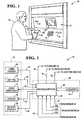
- the ATM 10comprises a user interface in the form of a front panel 12.
- the front panel 12includes a card reader 60, a key pad 16, a cash dispenser 18, a CRT display 20, and a receipt printer 22.
- the card reader 60has a card entry slot through which a customer 24 can insert a user identification card 26 at the commencement of a transaction to be conducted by the customer.
- the cash dispenser 18has a cash slot through which cash currency notes stored inside the ATM 10 can be delivered to the customer 24 during the transaction.
- the receipt printer 22has a receipt slot through which a receipt of the transaction is delivered to the customer 24 at termination of the transaction.
- the card readerWhen the customer 24 inserts the user identification card 26 into the card entry slot of the card reader 60, the card reader reads data contained on the card. The customer 24 is then prompted on the CRT display 20 to enter a personal identification number (PIN) via the key pad 16. After the correct PIN is entered, menus are displayed on the display 20 to enable the customer 24 to carry out the desired transaction. After the transaction is completed, the receipt printer 22 prints a receipt of the transaction and delivers the receipt through the slot of the receipt printer 22 to the customer 24.
- PINpersonal identification number
- the ATM 10further comprises a controller unit 30 which communicates with components of the front panel 12.
- the controller unit 30includes a microcomputer 32 and a memory 34 connected via bus line 36 to the microcomputer 32.
- the microcomputer 32receives input signals on lines 31, 33 from the card reader 60 and the key pad 16, respectively, and provides output signals on lines 35, 37, 39 to the cash dispenser 18, the display 20, and the receipt printer 22, respectively, to control the amount of cash dispensed by the cash dispensed by the cash dispenser 18, the information displayed on the display 20, and the information printed by the receipt printer 22.
- the memory 34may be non-volatile RAM. Suitable microcomputers and memories are readily available in the marketplace. Their structure and operation are well known and, therefore, will not be described.
- the microcomputer 32communicates via a line with a central terminal located remotely from the ATM 10.
- the lineis a proprietary network owned or leased by the financial institution owning the ATM 10.
- the remote central terminalmay be located at headquarters of the financial institution owning the ATM 10.
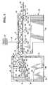
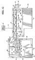
- the card reader 60comprises an enclosure 61 including a side wall portion 63 which is shown broken away in Fig. 3 to show details of a transport path 62 defined within the enclosure.
- the card entry slot of the card reader 60is designated as reference numeral 65" in Fig. 3 .
- the card entry slot 65is disposed at one end of the transport path 62.
- the card reader 60further includes a number of sensors 64a, 64b, 64c located along the transport path 62 , a plurality of drive rollers 66a, 66b, 66c, 66d which are disposed on one side of the transport path, and a plurality of idler rollers 68a, 68b, 68c, 68d which are disposed on the other side of the transport path.
- each of the sensors 64a, 64b, 64cincludes a light source located on one side of the transport path 62 and a light sensor facing the light source and located on the other side of the transport path.
- the sensors 64a, 64b, 64care collectively referred to herein as “sensors 64".
- the drive rollers 66a, 66b, 66c, 66dare collectively referred to herein as “drive rollers 66".
- the idler rollers 68a, 68b, 68c, 68dare collectively referred to herein as "idler rollers 68".
- An endless belt 57extends around the drive rollers 66, as shown in Fig. 3 .
- the endless belt 57defines the transport path 62.
- a drive motor 67is operatively coupled (schematically shown as broken line 47 in Fig. 3 ) to the drive rollers 66 to rotate these rollers about their longitudinal central axes.
- the drive motor 67is controlled by the microcomputer 32 via line 41 (shown only in Fig. 2 ).
- the microcomputer 32monitors signals on line 44a, 44b, 44c (shown only in Fig. 2 ) from the sensors 64a, 64b, 64c, respectively, and controls operation of the drive motor 67 on line 41 in response thereto.
- the drive motor 67drives the endless belt 57 to move a user identification card along the transport path 62 in a known manner.
- a card capture bin 80adjoins the card reader 60, as shown in Fig. 3 .
- the capture bin 80includes an enclosure 89 having a top wall portion 82 interconnecting opposite back and front wall portions 81, 83.
- a side wall portion 84 of the capture bin 80is shown broken away to show details of the interior of the capture bin.
- a generally rectangular slot 96is defined in the front wall portion 83. The slot 96 is aligned with the transport path 62 and has a size such that a user identification card is able to move from the transport path through the slot.
- a shutter mechanism 50is located in front of the card entry slot 65 of the card reader 60, as shown in Fig. 3 .
- the shutter mechanism 50has a shutter passage 51 which aligns with the card entry slot 65 such that the user identification card 26 inserted by the customer 24 is able to be moved through the shutter passage and the card entry slot into the transport path 62.
- the shutter mechanism 50includes a shutter door 52 which is movable between a closed position which blocks the shutter passage 51 (as shown in Fig. 3 ) and an open position which unblocks the shutter passage (as shown in Fig. 4 ) to allow the user identification card 26 to move through the shutter passage into the transport path 62.
- a sensor 54is disposed along the shutter passage 51 and is located in a position which enables the user identification card 26 being inserted by the customer 24 to be detected.
- the sensor 54detects the presence of the leading edge of the user identification card 26 in the shutter passage 51 (as shown in Fig. 3 )
- the sensor 54provides an output signal on line 45 (shown only in Fig. 2 ) indicative thereof.
- the microcomputer 32monitors the signal on line 45 and provides a control signal on line 46 to move the shutter door 52 from the closed position shown in Fig. 3 to the open position shown in Fig. 4 in response to the signal on line 45.
- the structure and operation of the shutter mechanism 50 including the shutter door 52are known and, therefore, will not be described in detail.
- the customer 24is allowed to further insert the leading edge of the user identification card 26 from the position shown in Fig. 4 to the position shown in Fig. 5 .
- the leading edge of the card 26engages the outer circumferential surface of the endless belt 57.
- the first sensor 64adetects the leading edge of the card and provides a signal on line 44a (shown only in Fig. 2 ) indicative thereof.
- the microcomputer 32produces a signal on line 41 to actuate the drive motor 67 to rotate the drive rollers 66 about their longitudinal central axes in a direction indicated by the arrows shown in the drive rollers 66 in Fig. 5 .
- the rotation of the drive rollers 66moves the endless belt 57 in the direction of arrow "B" shown in Fig. 5 . Since the leading edge of the card 26 engages the outer circumferential surface of the endless belt 57, the movement of the endless belt in the direction of arrow "B" in Fig. 5 results in movement of the card from the position shown in Fig. 5 to the position shown in Fig. 6 .
- the leading edge of the card 26is detected by the sensor 64c.
- the sensor 64cprovides a signal on line 44c ( Fig. 2 ) indicative thereof.
- the microcomputer 32produces a signal on line 41 to turn the motor 67 off and a signal on line 52 to close the shutter door 52.
- the customer 24is allowed to carry out the desired financial transaction.
- the shutter door 52is opened and the motor 67 is actuated to rotate in the opposite direction. This results in rotation of the drive rollers 66 in the opposite direction, as indicated by the arrows shown in the drive rollers 66 in Fig. 7 .
- the motor 67is actuated to cause the card to move from the position shown in Fig. 7 to the position shown in Fig. 8 . More specifically, the motor 67 is actuated to move the card 26 from the position shown in Fig. 7 to the position shown in Fig. 8 when the sensor 64a still detects the leading edge of the card 26 upon elapse of a predetermined amount of time since return of the card to the position shown in Fig. 7 . Immediately after the card 26 moves from the position shown in Fig. 7 to the position shown in Fig. 8 , the shutter door 52 closes as shown in Fig. 8 .
- the cardthen drops from the position shown in Fig. 8 to the position shown in Fig. 9 inside the capture bin 80.
- the card 26is thereby retained in the capture bin 80 to prevent a person who is not the card owner from taking the card.
- the first motor 67turns off. This feature of retaining the card 26 after elapse of a predetermined amount of time is well known.
- the capture bin 80includes an inwardly extending wall portion 90 having one end thereof fixedly connected to the back wall portion 81.
- the inwardly extending wall portion 90has an opposite free end 91 which extends inwardly to divide the space inside the capture bin into a lower compartment 85 and an upper compartment 86.
- a support piece 92interconnects the top wall portion 82 and the inwardly extending wall portion 90 to support the inwardly extending wall portion.
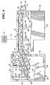
- One end of a diverter flap 87is pivotably connected via a pivot pin 88 to the free end 91 of the inwardly extending wall portion 90.
- the diverter flap 87is pivotable between an open position as shown in Fig. 7 and a closed position as shown in Fig. 10 .
- An energizable solenoid 94 having a rod 93 connected to the armature (not shown) of the solenoid 94is located in the upper compartment 86 and is fixedly mounted to the top wall portion 82.
- the solenoid 94is mounted to the top wall portion 82 such that the rod 93 extends in a downward direction as viewed in Fig. 7 .
- the rod 93is connected to the diverter flap 87 in a manner as shown in Fig. 7 to move the diverter flap from the open position shown in Fig. 7 to the closed position shown in Fig. 10 .
- the solenoid 94is shown in Fig. 7 in a de-engergized condition, and is shown in Fig. 10 in an energized condition.
- the microcomputer 32controls operation of the solenoid 94 in accordance with an application program stored in the memory unit 34 to control movement of the diverter flap 87 between the open position shown in Fig. 7 and the closed position shown in Fig. 10 .
- the movement of the diverter flap 87 between the open position shown in Fig. 7 and the closed position shown in Fig. 10will be described in detail later.
- a first roller 70is located in the upper compartment 86 and is rotatably mounted about its longitudinal central axis on a pivot pin 71 which is fixedly connected at one end to the side wall portion 84.
- a generally flat plate 79is mounted on the diverter flap 87 and is movable together with the diverter flap.
- a second roller 72is located in the upper compartment 86 and is rotatably mounted about its longitudinal central axis on a pivot pin 73 which is fixedly connected at one end to the flat plate 79.
- a third roller 74is located in the upper compartment 86 and is rotatably mounted about its longitudinal central axis on a pivot pin 75 which is fixedly connected at one end to the flat plate 79.
- a fourth roller 76is located in a generally rectangular opening 95 defined in the front wall portion 83.
- the fourth roller 76is rotatably mounted about its longitudinal central axis on a pivot pin 77 which is fixedly mounted between oppositely-facing interior edge surfaces 97 (only one of these edge surfaces 97 being shown in Fig. 7 ) defining the opening 95.
- the capture bin 80is positioned relative to the card reader 60 such that the outer circumferential surface of the fourth roller 76 frictionally engages the outer circumferential surface of the endless belt 57.
- a maintenence card 99which may be a diagnostic card, is located in the upper compartment 86.
- the diagnostic card 99has a size which is identical to the size of a standard magnetic stripe card.
- the diagnostic card 99contains magnetic data which, when read by the card reader 60, enables the microcomputer 32 to determine if components of the card reader are functioning smoothly and properly. The construction and operation of such diagnostic cards is well known and, therefore, will not be described.
- the diagnostic card 99resides in a position adjoining the card reader 60. As shown in Fig. 7 , one end of the diagnostic card 99 is frictionally engaged between the second and third rollers 72, 74. The other end of the diagnostic card 99 rests on the first roller 70.
- the diagnostic card 99is shown in Fig. 7 in a resting position.
- a sensor 98detects the presence of the diagnostic card 99 in its resting position and provides a signal on line 48 (shown only in Fig. 2 ) indicative thereof.
- the diagnostic card 99is movable from the position shown in Fig. 7 to a position shown in Fig. 10 .
- the diagnostic card 99is shown in Fig. 10 in a testing position.
- the movement of the diagnostic card 99 between the position shown in Fig. 7 and the position shown in Fig. 10is under control of an application program stored in the memory 34.
- the movement of the diagnostic card 99 between the position shown in Fig. 7 and the position shown in Fig. 10is described in detail hereinbelow.
- the diagnostic card 99is moved into the transport path 62 of the card reader 60 for the purpose of performing diagnostic tests on the card reader 60.
- the microcomputer 32provides a signal on line 43 to energize the solenoid 94.
- the rod 93 connected to the armature of the solenoid 94moves downward and thereby moves the diverter flap 87 from the open position shown in Fig. 7 to the closed position shown in Fig. 10 .
- the diverter flap 87is in the position shown in Fig. 10 , the outer circumferential surfaces of the third and fourth rollers 74, 76 frictionally engage each other.
- the microcomputer 32then produces a signal on line 42 to actuate the motor 67.
- the motor 67is actuated such that the drive rollers 66 rotate in a direction indicated by the arrow shown in the drive roller 66d in Fig. 10 .
- This rotationcauses the third and fourth rollers 74, 76 to rotate in the directions indicated by the arrows shown in the third and fourth rollers 74, 76 in Fig. 10 .
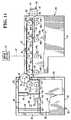
- the leading edge of the diagnostic card 99is detected by the sensor 64a.
- the sensor 64adetects the leading edge of the diagnostic card 99, the sensor 64a provides a signal on line 44a indicative thereof.
- the microcomputer 32In response to the signal on line 44a, the microcomputer 32 provides a signal on line 41 to rotate the motor 67 in the opposite direction which, in turn, results in rotation of the drive rollers 66 in the direction of the arrows shown in the drive rollers 66 shown in Fig. 11 . Also, the third and fourth rollers 74, 76 rotate in the directions indicated by the arrows shown in the third and fourth rollers 74, 76 in Fig. 11 . This results in return movement of the diagnostic card 99 from the position shown in Fig. 11 to the position shown in Fig. 12 . The return of the diagnostic card 99 back to the position shown in Fig. 12 is detected by the sensor 98 which provides a signal on line 48 indicative thereof. In response to the signal on line 48, the microcomputer 32 provides a signal on line 41 to turn off the motor 67 off.
- the card reader 60When the diagnostic card 99 is in the position shown in Fig. 11 , the card reader 60 reads the magnetic data contained on the diagnostic card. The microcomputer 32 then uses this magnetic data to perform diagnostic tests to determine if components of the card reader 60 are functioning smoothly and properly. If the microcomputer 32 determines that the card reader 60 passes all of the diagnostic tests, the microcomputer provides a signal indicative thereof. Upon this determination, the card reader 60 is ready to accept a user identification card from the next customer after the diagnostic card 99 returns to the resting position shown in Fig. 12 .
- the microcomputer 32determines that the card reader 60 has failed one or more of the diagnostic tests, the microcomputer 32 provides a signal indicating that the card reader 60 has malfunctioned and needs to be serviced. Upon this determination, the microcomputer 32 provides a signal on line 46 to disable the shutter door 52 as well as other signals required to disable the ATM 10 and prevent further use of the ATM. When disabled, the shutter door 52 is maintained in its closed position to prevent a user identification card from being inserted into the transport path 62.
- the microcomputer 32may send diagnostic-type messages to the remote central terminal. These messages are displayed on a display at the remote central terminal to provide the service technician with information useful in servicing the card reader 60.
- the diagnostic-type messagesmay contain information which suggests to the technician certain parts of the card reader 60 which may need to be replaced.
- the maintenance card 99may be a cleaning type of card instead of a diagnostic type of card. Cards of the cleaning type are known and commercially available. If the card 99 is of the cleaning type, parts of the card reader 60 are cleaned upon each complete movement of the card 99 from its resting position to its testing position and then back to its resting position. The movement of the card 99 would be controlled by a service technician located at the remote terminal, in the same manner as already described hereinabove.
- a single maintenance cardhas been described as residing in a position adjacent the card reader 60, it is contemplated that more than one card may reside in different positions adjacent the card reader 60.
- a structureis provided which allows the service technician located at the remote terminal 28 to selectively control movement of each card to perform different maintenance operations of the card reader 60.
- a number of advantagesresult by providing an ATM and a method of operating the ATM in accordance with the present invention.
- One advantageis that card readers of a large number of ATMs may be serviced by a single technician located at a remote terminal. This saves time for the technician resulting in cost savings.
- Another advantageis that ATMs currently in the field can be easily retrofitted at relatively low cost with features of the present invention.
- the technicianis able to identify spare components of the card reader which have the greatest chance of being needed for replacement, before actually going out to the particular ATM to service the card reader of that ATM when a service trip is required. Again, this saves time for the technician resulting in cost savings. Also, the quantity of spare components kept in inventory may be reduced.
- the maintenance card 99is a fraud tool detect card (FTDC). As described above, the card 99 can be moved from the resting position to the testing position.
- FTDCfraud tool detect card
- the microcomputer 32determines that the transport path 62 is clear and ready to accept a user identification card from the next customer.
- the ATM 10is enabled and ready to process the next financial transaction.
- the microcomputer 32determines that the transport path 62 is not clear and that a fraud tool device may be present in the transport path. Upon this determination, the microcomputer 32 provides a signal on line 46 to disable the shutter door 52 as well as other signals required to disable the ATM 10 and prevent further use of the ATM. When disabled, the shutter door 52 is maintained in its closed position to prevent a user identification card from being inserted into the transport path 62. This prevents a user identification card from being inserted and jammed in the transport path 62 if a fraud tool is present in the transport path.
- the foregoingdescribes movement of the FTDC 99 into the transport path 62 after completion of each financial transaction, it is possible that movement of the FTDC into the transport path could be effected before each financial transaction.
- the FTDC 99could be moved from its resting position to its testing position and then back to its resting position upon the sensor 64a detecting the presence of a user identification card.
- the shutter door 52would not open until the microcomputer 32 has determined that the FTDC 99 has successfully moved from the resting position shown in Fig. 10 to the testing position shown in Fig. 11 and then back to the resting position shown in Fig. 12 .
- a number of advantagesresult by providing an ATM and a method of operating the ATM in accordance with the present invention.
- One advantageis that the presence of a fraud tool device is detected before a user identification card is inserted into the card reader 60. Jamming of a user identification card by the fraud tool device is avoided.
- Another advantageis that ATMs currently in the field can be easily retrofitted at relatively low cost with features of the present invention.
Landscapes
- Business, Economics & Management (AREA)
- Accounting & Taxation (AREA)
- Physics & Mathematics (AREA)
- General Physics & Mathematics (AREA)
- Finance (AREA)
- Strategic Management (AREA)
- General Business, Economics & Management (AREA)
- Engineering & Computer Science (AREA)
- Theoretical Computer Science (AREA)
- Control Of Vending Devices And Auxiliary Devices For Vending Devices (AREA)
- Financial Or Insurance-Related Operations Such As Payment And Settlement (AREA)
Description
- The present invention relates to a self-service terminal (SST), and is particularly directed to an automated teller machine (ATM) and methods of maintaining a card reader, testing for a fraud tool, or cleaning parts of the ATM.
- A typical ATM includes a card reader having a transport path and a card entry slot at one end of the transport path for receiving a user identification card from an ATM user to enable the ATM user to gain access to the ATM. When a customer inserts a user identification card into the card entry slot of the card reader, the card reader reads data contained on the card. The customer is then prompted on a display to enter a personal identification number (PIN) via a key pad. After the correct PIN is entered, menus are displayed on the display to enable the customer to carry out the desired transaction.
- The card reader is a key component of the ATM. A service technician periodically performs maintenance operations on the card reader to maintain smooth and proper functioning of the card reader. A component failure in the card reader is often diagnosed by the service technician. Typically, the technician goes to the particular site of the failure and loads and executes diagnostic software, which alerts the technician of possible causes for the failure. The technician must then order parts. This method of diagnosing a card reader at an ATM is time-consuming and costly.
- It is one object of the invention to provide a method diagnosing a card reader which overcomes such problems.
- Another problem which may occur in an ATM is the use of a fraud tool device in a fraudulent scheme to steal a user identification card belonging to a legitimate ATM user is known. Typically, the person carrying out the fraudulent scheme inserts a fraud tool device into a card entry slot of a card reader of the ATM. The fraud tool device is then manipulated and positioned in the card entry slot so that a user identification card inserted by the next legitimate ATM user becomes jammed by the fraud tool device. Since the user identification card is jammed by the fraud tool device, the ATM user is unable to retrieve the card and eventually walks away from the ATM leaving the card behind. After the ATM user walks away from the ATM, the person carrying out the fraudulent scheme retrieves both the fraud tool device and the jammed user identification card. A number of known techniques have been applied in attempts to prevent a person from carrying out such a fraudulent scheme. A disadvantage in using the known techniques is that the presence of the fraud tool device is detected after a user identification card has been inserted into the ATM and jammed by the fraud tool device.
- According to the present invention there is provided a self-service terminal (SST) comprising a card reader having a transport path and a card entry slot at one end of the transport path for receiving a user identification card from an SST user to enable the SST user to gain access to the SST; means to retain a maintenance card in a resting position adjoining the card reader; a transport mechanism for moving the maintenance card between the resting position and a testing positions; and a processor unit for controlling the transport mechanism to move the maintenance card between the two positions, wherein the resting position is within a card capture bin having an opening, the capture bin being divided into a lower compartment and an upper compartment, by an inner wall and a pivotally mounted diverter flap, the maintenance card being located in the upper compartment and access to the lower compartment being gained through movement of the diverter flap, which is controlled by the processor unit, between an open position and a closed position, such that the maintenance card can be moved between the resting position and the testing position through opening when the diverter flap is in the closed position and such that retained cards can be moved to the lower compartment when the diverter flap is in the open position.
- The invention will now be described, by way of example, with reference to the accompanying drawings in which:
Fig. 1 is a perspective view of an automated teller machine (ATM) embodying the present invention;Fig. 2 is a block diagram representation of the ATM ofFig. 1 ;Fig. 3 is a view looking generally in the direction of arrow A ofFig. 1 , with certain portions broken away and some parts shown only schematically; andFig. 4-12 are views similar toFig. 3 and showing parts in different positions.- The
ATM 10 comprises a user interface in the form of afront panel 12. Thefront panel 12 includes acard reader 60, akey pad 16, acash dispenser 18, aCRT display 20, and areceipt printer 22. As particularly shown inFig. 1 , thecard reader 60 has a card entry slot through which acustomer 24 can insert auser identification card 26 at the commencement of a transaction to be conducted by the customer. Thecash dispenser 18 has a cash slot through which cash currency notes stored inside theATM 10 can be delivered to thecustomer 24 during the transaction. Thereceipt printer 22 has a receipt slot through which a receipt of the transaction is delivered to thecustomer 24 at termination of the transaction. - When the
customer 24 inserts theuser identification card 26 into the card entry slot of thecard reader 60, the card reader reads data contained on the card. Thecustomer 24 is then prompted on theCRT display 20 to enter a personal identification number (PIN) via thekey pad 16. After the correct PIN is entered, menus are displayed on thedisplay 20 to enable thecustomer 24 to carry out the desired transaction. After the transaction is completed, thereceipt printer 22 prints a receipt of the transaction and delivers the receipt through the slot of thereceipt printer 22 to thecustomer 24. - Referring particularly to
Fig. 2 , theATM 10 further comprises acontroller unit 30 which communicates with components of thefront panel 12. Thecontroller unit 30 includes amicrocomputer 32 and amemory 34 connected viabus line 36 to themicrocomputer 32. Themicrocomputer 32 receives input signals onlines card reader 60 and thekey pad 16, respectively, and provides output signals onlines cash dispenser 18, thedisplay 20, and thereceipt printer 22, respectively, to control the amount of cash dispensed by the cash dispensed by thecash dispenser 18, the information displayed on thedisplay 20, and the information printed by thereceipt printer 22. Thememory 34 may be non-volatile RAM. Suitable microcomputers and memories are readily available in the marketplace. Their structure and operation are well known and, therefore, will not be described. - The
microcomputer 32 communicates via a line with a central terminal located remotely from theATM 10. Preferably, the line is a proprietary network owned or leased by the financial institution owning theATM 10. The remote central terminal may be located at headquarters of the financial institution owning theATM 10. - Referring to
Fig. 3 , thecard reader 60 comprises anenclosure 61 including aside wall portion 63 which is shown broken away inFig. 3 to show details of atransport path 62 defined within the enclosure. The card entry slot of thecard reader 60 is designated asreference numeral 65" inFig. 3 . Thecard entry slot 65 is disposed at one end of thetransport path 62. Thecard reader 60 further includes a number ofsensors transport path 62 , a plurality ofdrive rollers idler rollers - Preferably, each of the
sensors transport path 62 and a light sensor facing the light source and located on the other side of the transport path. Thesensors sensors 64". Thedrive rollers idler rollers - An
endless belt 57 extends around the drive rollers 66, as shown inFig. 3 . Theendless belt 57 defines thetransport path 62. Adrive motor 67 is operatively coupled (schematically shown asbroken line 47 inFig. 3 ) to the drive rollers 66 to rotate these rollers about their longitudinal central axes. Thedrive motor 67 is controlled by themicrocomputer 32 via line 41 (shown only inFig. 2 ). Themicrocomputer 32 monitors signals online Fig. 2 ) from thesensors drive motor 67 online 41 in response thereto. Thedrive motor 67 drives theendless belt 57 to move a user identification card along thetransport path 62 in a known manner. - A card capture bin 80 adjoins the
card reader 60, as shown inFig. 3 . Thecapture bin 80 includes anenclosure 89 having atop wall portion 82 interconnecting opposite back andfront wall portions side wall portion 84 of thecapture bin 80 is shown broken away to show details of the interior of the capture bin. A generallyrectangular slot 96 is defined in thefront wall portion 83. Theslot 96 is aligned with thetransport path 62 and has a size such that a user identification card is able to move from the transport path through the slot. - A
shutter mechanism 50 is located in front of thecard entry slot 65 of thecard reader 60, as shown inFig. 3 . Theshutter mechanism 50 has ashutter passage 51 which aligns with thecard entry slot 65 such that theuser identification card 26 inserted by thecustomer 24 is able to be moved through the shutter passage and the card entry slot into thetransport path 62. Theshutter mechanism 50 includes ashutter door 52 which is movable between a closed position which blocks the shutter passage 51 (as shown inFig. 3 ) and an open position which unblocks the shutter passage (as shown inFig. 4 ) to allow theuser identification card 26 to move through the shutter passage into thetransport path 62. - A
sensor 54 is disposed along theshutter passage 51 and is located in a position which enables theuser identification card 26 being inserted by thecustomer 24 to be detected. When thesensor 54 detects the presence of the leading edge of theuser identification card 26 in the shutter passage 51 (as shown inFig. 3 ), thesensor 54 provides an output signal on line 45 (shown only inFig. 2 ) indicative thereof. Themicrocomputer 32 monitors the signal online 45 and provides a control signal online 46 to move theshutter door 52 from the closed position shown inFig. 3 to the open position shown inFig. 4 in response to the signal online 45. The structure and operation of theshutter mechanism 50 including theshutter door 52 are known and, therefore, will not be described in detail. - After the
shutter door 52 has moved from the closed position shown inFig. 3 to the open position shown inFig. 4 , thecustomer 24 is allowed to further insert the leading edge of theuser identification card 26 from the position shown inFig. 4 to the position shown inFig. 5 . InFig. 5 , the leading edge of thecard 26 engages the outer circumferential surface of theendless belt 57. - When the
user identification card 26 is in the position shown inFig. 5 , thefirst sensor 64a detects the leading edge of the card and provides a signal online 44a (shown only inFig. 2 ) indicative thereof. When this occurs, themicrocomputer 32 produces a signal online 41 to actuate thedrive motor 67 to rotate the drive rollers 66 about their longitudinal central axes in a direction indicated by the arrows shown in the drive rollers 66 inFig. 5 . The rotation of the drive rollers 66 moves theendless belt 57 in the direction of arrow "B" shown inFig. 5 . Since the leading edge of thecard 26 engages the outer circumferential surface of theendless belt 57, the movement of the endless belt in the direction of arrow "B" inFig. 5 results in movement of the card from the position shown inFig. 5 to the position shown inFig. 6 . - In
Fig. 6 , the leading edge of thecard 26 is detected by thesensor 64c. When this occurs, thesensor 64c provides a signal online 44c (Fig. 2 ) indicative thereof. In response to the signal online 44c, themicrocomputer 32 produces a signal online 41 to turn themotor 67 off and a signal online 52 to close theshutter door 52. While thecard 26 is in the position shown inFig. 6 , thecustomer 24 is allowed to carry out the desired financial transaction. After completion of the financial transaction, theshutter door 52 is opened and themotor 67 is actuated to rotate in the opposite direction. This results in rotation of the drive rollers 66 in the opposite direction, as indicated by the arrows shown in the drive rollers 66 inFig. 7 . The rotation of the drive rollers 66 moves theendless belt 57 in the direction of arrow "C" shown inFig. 7 . This results in movement of thecard 26 from the position shown inFig. 6 to the position shown inFig. 7 . Thecard 26 is thereby returned to thecustomer 24. - In the event that the
customer 24 forgets to take the returneduser identification card 26 shown inFig. 7 and walks away from theATM 10 after carrying out the financial transaction, themotor 67 is actuated to cause the card to move from the position shown inFig. 7 to the position shown inFig. 8 . More specifically, themotor 67 is actuated to move thecard 26 from the position shown inFig. 7 to the position shown inFig. 8 when thesensor 64a still detects the leading edge of thecard 26 upon elapse of a predetermined amount of time since return of the card to the position shown inFig. 7 . Immediately after thecard 26 moves from the position shown inFig. 7 to the position shown inFig. 8 , theshutter door 52 closes as shown inFig. 8 . - The card then drops from the position shown in
Fig. 8 to the position shown inFig. 9 inside thecapture bin 80. Thecard 26 is thereby retained in thecapture bin 80 to prevent a person who is not the card owner from taking the card. Shortly after thecard 26 drops from the position shown inFig. 8 to the position shown inFig. 9 , thefirst motor 67 turns off. This feature of retaining thecard 26 after elapse of a predetermined amount of time is well known. - With specific reference to
Fig. 7 in which thecustomer 24 has just completed a financial transaction, thecapture bin 80 includes an inwardly extendingwall portion 90 having one end thereof fixedly connected to theback wall portion 81. The inwardly extendingwall portion 90 has an oppositefree end 91 which extends inwardly to divide the space inside the capture bin into alower compartment 85 and anupper compartment 86. Asupport piece 92 interconnects thetop wall portion 82 and the inwardly extendingwall portion 90 to support the inwardly extending wall portion. One end of adiverter flap 87 is pivotably connected via apivot pin 88 to thefree end 91 of the inwardly extendingwall portion 90. Thediverter flap 87 is pivotable between an open position as shown inFig. 7 and a closed position as shown inFig. 10 . - An
energizable solenoid 94 having arod 93 connected to the armature (not shown) of thesolenoid 94 is located in theupper compartment 86 and is fixedly mounted to thetop wall portion 82. Thesolenoid 94 is mounted to thetop wall portion 82 such that therod 93 extends in a downward direction as viewed inFig. 7 . Therod 93 is connected to thediverter flap 87 in a manner as shown inFig. 7 to move the diverter flap from the open position shown inFig. 7 to the closed position shown inFig. 10 . Thesolenoid 94 is shown inFig. 7 in a de-engergized condition, and is shown inFig. 10 in an energized condition. Themicrocomputer 32 controls operation of thesolenoid 94 in accordance with an application program stored in thememory unit 34 to control movement of thediverter flap 87 between the open position shown inFig. 7 and the closed position shown inFig. 10 . The movement of thediverter flap 87 between the open position shown inFig. 7 and the closed position shown inFig. 10 will be described in detail later. - A
first roller 70 is located in theupper compartment 86 and is rotatably mounted about its longitudinal central axis on apivot pin 71 which is fixedly connected at one end to theside wall portion 84. A generallyflat plate 79 is mounted on thediverter flap 87 and is movable together with the diverter flap. Asecond roller 72 is located in theupper compartment 86 and is rotatably mounted about its longitudinal central axis on apivot pin 73 which is fixedly connected at one end to theflat plate 79. Athird roller 74 is located in theupper compartment 86 and is rotatably mounted about its longitudinal central axis on apivot pin 75 which is fixedly connected at one end to theflat plate 79. - A
fourth roller 76 is located in a generallyrectangular opening 95 defined in thefront wall portion 83. Thefourth roller 76 is rotatably mounted about its longitudinal central axis on apivot pin 77 which is fixedly mounted between oppositely-facing interior edge surfaces 97 (only one of these edge surfaces 97 being shown inFig. 7 ) defining theopening 95. Thecapture bin 80 is positioned relative to thecard reader 60 such that the outer circumferential surface of thefourth roller 76 frictionally engages the outer circumferential surface of theendless belt 57. - A
maintenence card 99, which may be a diagnostic card, is located in theupper compartment 86. Preferably, thediagnostic card 99 has a size which is identical to the size of a standard magnetic stripe card. Thediagnostic card 99 contains magnetic data which, when read by thecard reader 60, enables themicrocomputer 32 to determine if components of the card reader are functioning smoothly and properly. The construction and operation of such diagnostic cards is well known and, therefore, will not be described. - In accordance with the present invention, the
diagnostic card 99 resides in a position adjoining thecard reader 60. As shown inFig. 7 , one end of thediagnostic card 99 is frictionally engaged between the second andthird rollers diagnostic card 99 rests on thefirst roller 70. Thediagnostic card 99 is shown inFig. 7 in a resting position. Asensor 98 detects the presence of thediagnostic card 99 in its resting position and provides a signal on line 48 (shown only inFig. 2 ) indicative thereof. Thediagnostic card 99 is movable from the position shown inFig. 7 to a position shown inFig. 10 . Thediagnostic card 99 is shown inFig. 10 in a testing position. The movement of thediagnostic card 99 between the position shown inFig. 7 and the position shown inFig. 10 is under control of an application program stored in thememory 34. The movement of thediagnostic card 99 between the position shown inFig. 7 and the position shown inFig. 10 is described in detail hereinbelow. - Upon the
microcomputer 32 receiving a command signal from the remote terminal 28 in response to an input from a service technician located at the remote terminal, thediagnostic card 99 is moved into thetransport path 62 of thecard reader 60 for the purpose of performing diagnostic tests on thecard reader 60. When this occurs, themicrocomputer 32 provides a signal online 43 to energize thesolenoid 94. When energized, therod 93 connected to the armature of thesolenoid 94 moves downward and thereby moves thediverter flap 87 from the open position shown inFig. 7 to the closed position shown inFig. 10 . When thediverter flap 87 is in the position shown inFig. 10 , the outer circumferential surfaces of the third andfourth rollers - The
microcomputer 32 then produces a signal on line 42 to actuate themotor 67. Themotor 67 is actuated such that the drive rollers 66 rotate in a direction indicated by the arrow shown in thedrive roller 66d inFig. 10 . This rotation, in turn, causes the third andfourth rollers fourth rollers Fig. 10 . - The rotation of the third and
fourth rollers diagnostic card 99 from the position shown inFig. 10 to the position shown inFig. 11 . InFig. 11 , the leading edge of thediagnostic card 99 is detected by thesensor 64a. When thesensor 64a detects the leading edge of thediagnostic card 99, thesensor 64a provides a signal online 44a indicative thereof. - In response to the signal on
line 44a, themicrocomputer 32 provides a signal online 41 to rotate themotor 67 in the opposite direction which, in turn, results in rotation of the drive rollers 66 in the direction of the arrows shown in the drive rollers 66 shown inFig. 11 . Also, the third andfourth rollers fourth rollers Fig. 11 . This results in return movement of thediagnostic card 99 from the position shown inFig. 11 to the position shown inFig. 12 . The return of thediagnostic card 99 back to the position shown inFig. 12 is detected by thesensor 98 which provides a signal online 48 indicative thereof. In response to the signal online 48, themicrocomputer 32 provides a signal online 41 to turn off themotor 67 off. - When the
diagnostic card 99 is in the position shown inFig. 11 , thecard reader 60 reads the magnetic data contained on the diagnostic card. Themicrocomputer 32 then uses this magnetic data to perform diagnostic tests to determine if components of thecard reader 60 are functioning smoothly and properly. If themicrocomputer 32 determines that thecard reader 60 passes all of the diagnostic tests, the microcomputer provides a signal indicative thereof. Upon this determination, thecard reader 60 is ready to accept a user identification card from the next customer after thediagnostic card 99 returns to the resting position shown inFig. 12 . - However, if the
microcomputer 32 determines that thecard reader 60 has failed one or more of the diagnostic tests, themicrocomputer 32 provides a signal indicating that thecard reader 60 has malfunctioned and needs to be serviced. Upon this determination, themicrocomputer 32 provides a signal online 46 to disable theshutter door 52 as well as other signals required to disable theATM 10 and prevent further use of the ATM. When disabled, theshutter door 52 is maintained in its closed position to prevent a user identification card from being inserted into thetransport path 62. - When the
microcomputer 32 determines that thecard reader 60 is not operating properly and needs to be serviced, themicrocomputer 32 may send diagnostic-type messages to the remote central terminal. These messages are displayed on a display at the remote central terminal to provide the service technician with information useful in servicing thecard reader 60. For example, the diagnostic-type messages may contain information which suggests to the technician certain parts of thecard reader 60 which may need to be replaced. - It is contemplated that the
maintenance card 99 may be a cleaning type of card instead of a diagnostic type of card. Cards of the cleaning type are known and commercially available. If thecard 99 is of the cleaning type, parts of thecard reader 60 are cleaned upon each complete movement of thecard 99 from its resting position to its testing position and then back to its resting position. The movement of thecard 99 would be controlled by a service technician located at the remote terminal, in the same manner as already described hereinabove. - Although a single maintenance card has been described as residing in a position adjacent the
card reader 60, it is contemplated that more than one card may reside in different positions adjacent thecard reader 60. In this case, a structure is provided which allows the service technician located at the remote terminal 28 to selectively control movement of each card to perform different maintenance operations of thecard reader 60. - A number of advantages result by providing an ATM and a method of operating the ATM in accordance with the present invention. One advantage is that card readers of a large number of ATMs may be serviced by a single technician located at a remote terminal. This saves time for the technician resulting in cost savings. Another advantage is that ATMs currently in the field can be easily retrofitted at relatively low cost with features of the present invention. Still another advantage is that the technician is able to identify spare components of the card reader which have the greatest chance of being needed for replacement, before actually going out to the particular ATM to service the card reader of that ATM when a service trip is required. Again, this saves time for the technician resulting in cost savings. Also, the quantity of spare components kept in inventory may be reduced.
- In a variation, the
maintenance card 99 is a fraud tool detect card (FTDC). As described above, thecard 99 can be moved from the resting position to the testing position. - When the
FTDC 99 is able to complete the entire movement from the position shown inFig. 10 to the position shown inFig. 11 and then back to the position shown inFig. 12 , themicrocomputer 32 determines that thetransport path 62 is clear and ready to accept a user identification card from the next customer. TheATM 10 is enabled and ready to process the next financial transaction. - However, if the
FTDC 99 is unable to move completely from the position shown inFig. 10 to the position shown inFig. 11 and then return completely from the position shown inFig. 11 to the position shown inFig. 12 , then themicrocomputer 32 determines that thetransport path 62 is not clear and that a fraud tool device may be present in the transport path. Upon this determination, themicrocomputer 32 provides a signal online 46 to disable theshutter door 52 as well as other signals required to disable theATM 10 and prevent further use of the ATM. When disabled, theshutter door 52 is maintained in its closed position to prevent a user identification card from being inserted into thetransport path 62. This prevents a user identification card from being inserted and jammed in thetransport path 62 if a fraud tool is present in the transport path. - Although the foregoing describes movement of the
FTDC 99 into thetransport path 62 after completion of each financial transaction, it is possible that movement of the FTDC into the transport path could be effected before each financial transaction. For example, theFTDC 99 could be moved from its resting position to its testing position and then back to its resting position upon thesensor 64a detecting the presence of a user identification card. Theshutter door 52 would not open until themicrocomputer 32 has determined that theFTDC 99 has successfully moved from the resting position shown inFig. 10 to the testing position shown inFig. 11 and then back to the resting position shown inFig. 12 . - A number of advantages result by providing an ATM and a method of operating the ATM in accordance with the present invention. One advantage is that the presence of a fraud tool device is detected before a user identification card is inserted into the
card reader 60. Jamming of a user identification card by the fraud tool device is avoided. Another advantage is that ATMs currently in the field can be easily retrofitted at relatively low cost with features of the present invention.
Claims (6)
- A self-service terminal (SST) (10) comprising:a card reader (60) having a transport path (62) and a card entry slot (65) at one end of the transport path for receiving a user identification card from an SST user to enable the SST user to gain access to the SST;means (70, 73, 75) to retain a maintenance card (99) in a resting position adjoining the card reader;a transport mechanism (57, 66, 70, 72, 74, 76, 94) for moving the maintenance card (99) between the resting position and a testing position; anda processor unit (30) for controlling the transport mechanism to move the maintenance card (99) between the two positions,wherein the resting position is within a card capture bin (80) having an opening (95), the capture bin being divided into a lower compartment (85) and an upper compartment (86), by an inner wall (90) and a pivotally mounted diverter flap (87), the maintenance card (26) being located in the upper compartment (86) and access to the lower compartment being gained through movement of the diverter flap (87), which is controlled by the processor unit (30), between an open position and a closed position, such that the maintenance card (99) can be moved between the resting position and the testing position through opening (95) when the diverter flap (87) is in the closed position and such that retained cards (26) can be moved to the lower compartment (85) when the diverter flap (87) is in the open position.
- An SST according to claim 1, in which the testing position is within the card reader (60).
- An SST according to claim 2, in which the transport mechanism (57, 66) is also arranged to move a user identification card between the card entry slot (65) and the testing position.
- An SST according to any preceding claim, in which the card reader (60) includes a number of sensors (64) located along the transport path for detecting the presence of either a user identification card or the maintenance card (99) along the transport path (62).
- An SST according to claim 4, in which each sensor (64) includes a light source located on one side of the transport path (62) and a light sensor facing the light source and located on the other side of the transport path.
- An SST according to any preceding claim further comprising means of connecting to a remote terminal.
Applications Claiming Priority (4)
| Application Number | Priority Date | Filing Date | Title |
|---|---|---|---|
| GBGB9626197.9AGB9626197D0 (en) | 1996-12-18 | 1996-12-18 | Self-service terminal and method of performing a maintenance operation of a card reader of a self-service terminal |
| GB9626196 | 1996-12-18 | ||
| GB9626197 | 1996-12-18 | ||
| GBGB9626196.1AGB9626196D0 (en) | 1996-12-18 | 1996-12-18 | Self-service terminal (sst) and a method of oerating the sst to control movement of a card of the sst |
Publications (3)
| Publication Number | Publication Date |
|---|---|
| EP0854461A2 EP0854461A2 (en) | 1998-07-22 |
| EP0854461A3 EP0854461A3 (en) | 2004-12-15 |
| EP0854461B1true EP0854461B1 (en) | 2008-10-15 |
Family
ID=26310657
Family Applications (1)
| Application Number | Title | Priority Date | Filing Date |
|---|---|---|---|
| EP97309113AExpired - LifetimeEP0854461B1 (en) | 1996-12-18 | 1997-11-13 | Self service terminal (SST) with maintenance feature |
Country Status (4)
| Country | Link |
|---|---|
| EP (1) | EP0854461B1 (en) |
| JP (1) | JP4500375B2 (en) |
| DE (1) | DE69739043D1 (en) |
| ES (1) | ES2312172T3 (en) |
Cited By (25)
| Publication number | Priority date | Publication date | Assignee | Title |
|---|---|---|---|---|
| US7494058B2 (en) | 2004-07-01 | 2009-02-24 | American Express Travel Related Services Company, Inc. | Smartcard transaction method and system using voiceprint recognition |
| US7494414B2 (en) | 2003-09-12 | 2009-02-24 | Igt | Gaming device having a card management system for the management of circulating data cards |
| US7506819B2 (en) | 2001-07-10 | 2009-03-24 | Xatra Fund Mx, Llc | Biometric security using a fob |
| US7543738B1 (en) | 2001-07-10 | 2009-06-09 | American Express Travel Related Services Company, Inc. | System and method for secure transactions manageable by a transaction account provider |
| US7578448B2 (en) | 2001-07-10 | 2009-08-25 | Blayn W Beenau | Authorizing radio frequency transactions using a keystroke scan |
| US7607583B2 (en) | 2001-07-10 | 2009-10-27 | American Express Travel Related Services Company, Inc. | Clear contactless card |
| US7639116B2 (en) | 2001-07-10 | 2009-12-29 | Peter D Saunders | Converting account data associated with a radio frequency device |
| US7668750B2 (en) | 2001-07-10 | 2010-02-23 | David S Bonalle | Securing RF transactions using a transactions counter |
| US7705732B2 (en) | 2001-07-10 | 2010-04-27 | Fred Bishop | Authenticating an RF transaction using a transaction counter |
| US7725427B2 (en) | 2001-05-25 | 2010-05-25 | Fred Bishop | Recurrent billing maintenance with radio frequency payment devices |
| US7793845B2 (en) | 2004-07-01 | 2010-09-14 | American Express Travel Related Services Company, Inc. | Smartcard transaction system and method |
| US7827106B2 (en) | 2001-07-10 | 2010-11-02 | American Express Travel Related Services Company, Inc. | System and method for manufacturing a punch-out RFID transaction device |
| US7837118B2 (en) | 1999-09-07 | 2010-11-23 | American Express Travel Related Services Company, Inc. | Infrared blocking article |
| US7886157B2 (en) | 2001-07-10 | 2011-02-08 | Xatra Fund Mx, Llc | Hand geometry recognition biometrics on a fob |
| US7889052B2 (en) | 2001-07-10 | 2011-02-15 | Xatra Fund Mx, Llc | Authorizing payment subsequent to RF transactions |
| US8001054B1 (en) | 2001-07-10 | 2011-08-16 | American Express Travel Related Services Company, Inc. | System and method for generating an unpredictable number using a seeded algorithm |
| US8057296B2 (en) | 2003-09-12 | 2011-11-15 | Igt | Gaming device including a card processing assembly having vertically-stacked card holders operable with thermally-printable data cards and portable card changeover machines |
| US8061913B2 (en) | 2003-09-02 | 2011-11-22 | Igt | Machine having a card processing assembly |
| US8066190B2 (en) | 1999-09-07 | 2011-11-29 | American Express Travel Related Services Company, Inc. | Transaction card |
| USRE43157E1 (en) | 2002-09-12 | 2012-02-07 | Xatra Fund Mx, Llc | System and method for reassociating an account number to another transaction account |
| US8197334B2 (en) | 2007-10-29 | 2012-06-12 | Igt | Circulating data card apparatus and management system |
| US8284025B2 (en) | 2001-07-10 | 2012-10-09 | Xatra Fund Mx, Llc | Method and system for auditory recognition biometrics on a FOB |
| USRE45416E1 (en) | 2001-07-10 | 2015-03-17 | Xatra Fund Mx, Llc | Processing an RF transaction using a routing number |
| US9031880B2 (en) | 2001-07-10 | 2015-05-12 | Iii Holdings 1, Llc | Systems and methods for non-traditional payment using biometric data |
| US9454752B2 (en) | 2001-07-10 | 2016-09-27 | Chartoleaux Kg Limited Liability Company | Reload protocol at a transaction processing entity |
Families Citing this family (7)
| Publication number | Priority date | Publication date | Assignee | Title |
|---|---|---|---|---|
| US7837116B2 (en) | 1999-09-07 | 2010-11-23 | American Express Travel Related Services Company, Inc. | Transaction card |
| GB0007361D0 (en) | 2000-03-28 | 2000-05-17 | Ncr Int Inc | Self-service terminal |
| JP5193409B2 (en)* | 2001-09-21 | 2013-05-08 | 株式会社東芝 | Inspection method and test medium for paper sheet processing apparatus and paper sheet processing apparatus |
| AT501236B1 (en)* | 2004-06-29 | 2007-07-15 | Keba Ag | READER FOR CARDBOARD CARRIER AND OPERATING PROCEDURES THEREFOR |
| US8251282B2 (en)* | 2007-12-20 | 2012-08-28 | Ncr Corporation | Card reader device with sensor for sensing card trapping device |
| EP3769290B1 (en)* | 2018-03-21 | 2025-04-23 | Diebold Nixdorf Incorporated | Self service terminal with magnetic card reader and optical scanner |
| CN111932798B (en)* | 2020-08-19 | 2022-08-09 | 中国银行股份有限公司 | Card-retaining processing method and device |
Family Cites Families (6)
| Publication number | Priority date | Publication date | Assignee | Title |
|---|---|---|---|---|
| JPS60123980A (en)* | 1983-12-08 | 1985-07-02 | Mitsubishi Heavy Ind Ltd | Test device of card processing machine |
| JPS60241158A (en)* | 1984-05-16 | 1985-11-30 | Toshiba Corp | Transaction test equipment for automatic transaction equipment |
| FR2587132B1 (en)* | 1985-09-12 | 1987-11-20 | Bull Transac | METHOD FOR CONFISCATION OF A CARD FOR A MIXED READER AND MIXED READER |
| JPH02244296A (en)* | 1989-03-17 | 1990-09-28 | Hitachi Ltd | Passbook handling device |
| JP2754745B2 (en)* | 1989-06-15 | 1998-05-20 | 株式会社日立製作所 | Remote maintenance system for automatic teller machine |
| JP2654611B2 (en)* | 1994-12-26 | 1997-09-17 | 日本電気株式会社 | Cash machine |
- 1997
- 1997-11-13DEDE69739043Tpatent/DE69739043D1/ennot_activeExpired - Lifetime
- 1997-11-13EPEP97309113Apatent/EP0854461B1/ennot_activeExpired - Lifetime
- 1997-11-13ESES97309113Tpatent/ES2312172T3/ennot_activeExpired - Lifetime
- 1997-11-27JPJP32605097Apatent/JP4500375B2/ennot_activeExpired - Fee Related
Cited By (33)
| Publication number | Priority date | Publication date | Assignee | Title |
|---|---|---|---|---|
| US8066190B2 (en) | 1999-09-07 | 2011-11-29 | American Express Travel Related Services Company, Inc. | Transaction card |
| US7837118B2 (en) | 1999-09-07 | 2010-11-23 | American Express Travel Related Services Company, Inc. | Infrared blocking article |
| US7725427B2 (en) | 2001-05-25 | 2010-05-25 | Fred Bishop | Recurrent billing maintenance with radio frequency payment devices |
| US7889052B2 (en) | 2001-07-10 | 2011-02-15 | Xatra Fund Mx, Llc | Authorizing payment subsequent to RF transactions |
| US7506819B2 (en) | 2001-07-10 | 2009-03-24 | Xatra Fund Mx, Llc | Biometric security using a fob |
| US7607583B2 (en) | 2001-07-10 | 2009-10-27 | American Express Travel Related Services Company, Inc. | Clear contactless card |
| US7639116B2 (en) | 2001-07-10 | 2009-12-29 | Peter D Saunders | Converting account data associated with a radio frequency device |
| US7637434B2 (en) | 2001-07-10 | 2009-12-29 | Blayn W Beenau | Registering a biometric for radio frequency transactions |
| US7668750B2 (en) | 2001-07-10 | 2010-02-23 | David S Bonalle | Securing RF transactions using a transactions counter |
| US7690577B2 (en) | 2001-07-10 | 2010-04-06 | Blayn W Beenau | Registering a biometric for radio frequency transactions |
| US7705732B2 (en) | 2001-07-10 | 2010-04-27 | Fred Bishop | Authenticating an RF transaction using a transaction counter |
| US7543738B1 (en) | 2001-07-10 | 2009-06-09 | American Express Travel Related Services Company, Inc. | System and method for secure transactions manageable by a transaction account provider |
| US9454752B2 (en) | 2001-07-10 | 2016-09-27 | Chartoleaux Kg Limited Liability Company | Reload protocol at a transaction processing entity |
| US7827106B2 (en) | 2001-07-10 | 2010-11-02 | American Express Travel Related Services Company, Inc. | System and method for manufacturing a punch-out RFID transaction device |
| US8284025B2 (en) | 2001-07-10 | 2012-10-09 | Xatra Fund Mx, Llc | Method and system for auditory recognition biometrics on a FOB |
| US7886157B2 (en) | 2001-07-10 | 2011-02-08 | Xatra Fund Mx, Llc | Hand geometry recognition biometrics on a fob |
| US9031880B2 (en) | 2001-07-10 | 2015-05-12 | Iii Holdings 1, Llc | Systems and methods for non-traditional payment using biometric data |
| US7578448B2 (en) | 2001-07-10 | 2009-08-25 | Blayn W Beenau | Authorizing radio frequency transactions using a keystroke scan |
| USRE45416E1 (en) | 2001-07-10 | 2015-03-17 | Xatra Fund Mx, Llc | Processing an RF transaction using a routing number |
| US8266056B2 (en) | 2001-07-10 | 2012-09-11 | American Express Travel Related Services Company, Inc. | System and method for manufacturing a punch-out RFID transaction device |
| US8001054B1 (en) | 2001-07-10 | 2011-08-16 | American Express Travel Related Services Company, Inc. | System and method for generating an unpredictable number using a seeded algorithm |
| US8548927B2 (en) | 2001-07-10 | 2013-10-01 | Xatra Fund Mx, Llc | Biometric registration for facilitating an RF transaction |
| USRE43157E1 (en) | 2002-09-12 | 2012-02-07 | Xatra Fund Mx, Llc | System and method for reassociating an account number to another transaction account |
| US8500349B2 (en) | 2003-09-02 | 2013-08-06 | Igt | Machine having a card processing assembly |
| US8210759B2 (en) | 2003-09-02 | 2012-07-03 | Igt | Machine having a card processing assembly |
| US8061913B2 (en) | 2003-09-02 | 2011-11-22 | Igt | Machine having a card processing assembly |
| US8057296B2 (en) | 2003-09-12 | 2011-11-15 | Igt | Gaming device including a card processing assembly having vertically-stacked card holders operable with thermally-printable data cards and portable card changeover machines |
| US8523664B2 (en) | 2003-09-12 | 2013-09-03 | Igt | Machine having a card processing assembly |
| US7494414B2 (en) | 2003-09-12 | 2009-02-24 | Igt | Gaming device having a card management system for the management of circulating data cards |
| US8016191B2 (en) | 2004-07-01 | 2011-09-13 | American Express Travel Related Services Company, Inc. | Smartcard transaction system and method |
| US7494058B2 (en) | 2004-07-01 | 2009-02-24 | American Express Travel Related Services Company, Inc. | Smartcard transaction method and system using voiceprint recognition |
| US7793845B2 (en) | 2004-07-01 | 2010-09-14 | American Express Travel Related Services Company, Inc. | Smartcard transaction system and method |
| US8197334B2 (en) | 2007-10-29 | 2012-06-12 | Igt | Circulating data card apparatus and management system |
Also Published As
| Publication number | Publication date |
|---|---|
| ES2312172T3 (en) | 2009-02-16 |
| JPH10247265A (en) | 1998-09-14 |
| JP4500375B2 (en) | 2010-07-14 |
| EP0854461A3 (en) | 2004-12-15 |
| EP0854461A2 (en) | 1998-07-22 |
| DE69739043D1 (en) | 2008-11-27 |
Similar Documents
| Publication | Publication Date | Title |
|---|---|---|
| EP0854461B1 (en) | Self service terminal (SST) with maintenance feature | |
| US5861614A (en) | Self-service terminal and method of performing a maintenance operation of a card reader of a self-service terminal | |
| US5929413A (en) | Self-service terminal (SST) and method of operating the SST to control movement of a card of the SST | |
| US4997076A (en) | Merchandise transaction machine and system with emergency operational modes | |
| RU2232423C2 (en) | Automation to implement transactions with testing of transfer channel | |
| US7000778B2 (en) | Bill handling machine | |
| US4600828A (en) | Automatic issuance of passbooks and the like | |
| US6520408B1 (en) | Method for operating automated banking machine | |
| EP2546809B1 (en) | Paper currency handling apparatus and method of depositing paper currencies using same | |
| US7523857B1 (en) | ATM with security sensing system for cash dispenser customer interface gate | |
| KR910005330B1 (en) | Remote monitoring and control system | |
| CA2305319C (en) | Automated banking machine with self auditing capabilities and system | |
| US20040220859A1 (en) | Self service checkout system | |
| EP1544807A2 (en) | Improved media transport cassette | |
| KR0140967B1 (en) | Automated Transaction Device Monitoring System | |
| JP3784899B2 (en) | Automatic record recovery device | |
| EP1002301B1 (en) | Method and apparatus for performing transactions | |
| RU2206125C2 (en) | Electronic automatic teller machine and system with separate audit means | |
| JP3383135B2 (en) | Power off control device in window system | |
| JPH0325234Y2 (en) | ||
| JP2003108948A (en) | Card processing equipment | |
| EP1950712A1 (en) | Automated banking machine with self auditing capabilities and system | |
| JPH1021447A (en) | Passbook processor | |
| JP2010102389A (en) | Vending machine management system, electronic settlement device, and analysis device | |
| JPH07152841A (en) | Transaction equipment automatic check method |
Legal Events
| Date | Code | Title | Description |
|---|---|---|---|
| PUAI | Public reference made under article 153(3) epc to a published international application that has entered the european phase | Free format text:ORIGINAL CODE: 0009012 | |
| AK | Designated contracting states | Kind code of ref document:A2 Designated state(s):AT BE CH DE DK ES FI FR GB GR IE IT LI LU MC NL PT SE | |
| AX | Request for extension of the european patent | Free format text:AL;LT;LV;MK;RO;SI | |
| PUAL | Search report despatched | Free format text:ORIGINAL CODE: 0009013 | |
| AK | Designated contracting states | Kind code of ref document:A3 Designated state(s):AT BE CH DE DK ES FI FR GB GR IE IT LI LU MC NL PT SE | |
| AX | Request for extension of the european patent | Extension state:AL LT LV MK RO SI | |
| RIC1 | Information provided on ipc code assigned before grant | Ipc:7G 06K 13/08 B Ipc:7G 07F 19/00 A | |
| 17P | Request for examination filed | Effective date:20050615 | |
| AKX | Designation fees paid | Designated state(s):DE ES FR GB IT | |
| 17Q | First examination report despatched | Effective date:20060309 | |
| GRAP | Despatch of communication of intention to grant a patent | Free format text:ORIGINAL CODE: EPIDOSNIGR1 | |
| GRAS | Grant fee paid | Free format text:ORIGINAL CODE: EPIDOSNIGR3 | |
| GRAA | (expected) grant | Free format text:ORIGINAL CODE: 0009210 | |
| AK | Designated contracting states | Kind code of ref document:B1 Designated state(s):DE ES FR GB IT | |
| REG | Reference to a national code | Ref country code:GB Ref legal event code:FG4D | |
| REG | Reference to a national code | Ref country code:GB Ref legal event code:746 Effective date:20081029 | |
| REF | Corresponds to: | Ref document number:69739043 Country of ref document:DE Date of ref document:20081127 Kind code of ref document:P | |
| REG | Reference to a national code | Ref country code:ES Ref legal event code:FG2A Ref document number:2312172 Country of ref document:ES Kind code of ref document:T3 | |
| PLBE | No opposition filed within time limit | Free format text:ORIGINAL CODE: 0009261 | |
| STAA | Information on the status of an ep patent application or granted ep patent | Free format text:STATUS: NO OPPOSITION FILED WITHIN TIME LIMIT | |
| 26N | No opposition filed | Effective date:20090716 | |
| PGFP | Annual fee paid to national office [announced via postgrant information from national office to epo] | Ref country code:FR Payment date:20101026 Year of fee payment:14 | |
| PGFP | Annual fee paid to national office [announced via postgrant information from national office to epo] | Ref country code:DE Payment date:20101111 Year of fee payment:14 | |
| PG25 | Lapsed in a contracting state [announced via postgrant information from national office to epo] | Ref country code:IT Free format text:LAPSE BECAUSE OF NON-PAYMENT OF DUE FEES Effective date:20091113 | |
| PGFP | Annual fee paid to national office [announced via postgrant information from national office to epo] | Ref country code:GB Payment date:20101118 Year of fee payment:14 | |
| PGFP | Annual fee paid to national office [announced via postgrant information from national office to epo] | Ref country code:ES Payment date:20101122 Year of fee payment:14 | |
| PGFP | Annual fee paid to national office [announced via postgrant information from national office to epo] | Ref country code:IT Payment date:20101124 Year of fee payment:14 | |
| PGRI | Patent reinstated in contracting state [announced from national office to epo] | Ref country code:IT Effective date:20110616 | |
| GBPC | Gb: european patent ceased through non-payment of renewal fee | Effective date:20111113 | |
| REG | Reference to a national code | Ref country code:FR Ref legal event code:ST Effective date:20120731 | |
| PG25 | Lapsed in a contracting state [announced via postgrant information from national office to epo] | Ref country code:IT Free format text:LAPSE BECAUSE OF NON-PAYMENT OF DUE FEES Effective date:20111113 | |
| REG | Reference to a national code | Ref country code:DE Ref legal event code:R119 Ref document number:69739043 Country of ref document:DE Effective date:20120601 | |
| PG25 | Lapsed in a contracting state [announced via postgrant information from national office to epo] | Ref country code:GB Free format text:LAPSE BECAUSE OF NON-PAYMENT OF DUE FEES Effective date:20111113 | |
| PG25 | Lapsed in a contracting state [announced via postgrant information from national office to epo] | Ref country code:FR Free format text:LAPSE BECAUSE OF NON-PAYMENT OF DUE FEES Effective date:20111130 | |
| REG | Reference to a national code | Ref country code:ES Ref legal event code:FD2A Effective date:20130603 | |
| PG25 | Lapsed in a contracting state [announced via postgrant information from national office to epo] | Ref country code:DE Free format text:LAPSE BECAUSE OF NON-PAYMENT OF DUE FEES Effective date:20120601 | |
| PG25 | Lapsed in a contracting state [announced via postgrant information from national office to epo] | Ref country code:ES Free format text:LAPSE BECAUSE OF NON-PAYMENT OF DUE FEES Effective date:20111114 |