EP0854353A2 - Route determination in a vehicle navigation system - Google Patents
Route determination in a vehicle navigation systemDownload PDFInfo
- Publication number
- EP0854353A2 EP0854353A2EP98300263AEP98300263AEP0854353A2EP 0854353 A2EP0854353 A2EP 0854353A2EP 98300263 AEP98300263 AEP 98300263AEP 98300263 AEP98300263 AEP 98300263AEP 0854353 A2EP0854353 A2EP 0854353A2
- Authority
- EP
- European Patent Office
- Prior art keywords
- route
- partial
- generation
- road
- navigation system
- Prior art date
- Legal status (The legal status is an assumption and is not a legal conclusion. Google has not performed a legal analysis and makes no representation as to the accuracy of the status listed.)
- Granted
Links
Images


Classifications
- G—PHYSICS
- G01—MEASURING; TESTING
- G01C—MEASURING DISTANCES, LEVELS OR BEARINGS; SURVEYING; NAVIGATION; GYROSCOPIC INSTRUMENTS; PHOTOGRAMMETRY OR VIDEOGRAMMETRY
- G01C21/00—Navigation; Navigational instruments not provided for in groups G01C1/00 - G01C19/00
- G01C21/26—Navigation; Navigational instruments not provided for in groups G01C1/00 - G01C19/00 specially adapted for navigation in a road network
- G01C21/34—Route searching; Route guidance
- G01C21/3446—Details of route searching algorithms, e.g. Dijkstra, A*, arc-flags or using precalculated routes
Definitions
- the present inventionrelates to the determination of routes in a vehicle navigation system.
- Various methods and apparatuswill be described below, by way of example in illustration of the invention, for determining an optimal route to a user's final destination.
- a usermay begin driving before the entire route to the final destination has been determined due to the generation of one or more intermediate routes.
- methods and apparatuswill be described for quickly generating an optimal route to the final destination, "seaming" the optimal route with the intermediate route, and determining a termination point for the intermediate route.
- Also described hereinis a method and apparatus for optimizing route generation in a grid pattern region.
- A*artificial intelligence graph search technique
- A*performs a directed, breadth-first search through the graph, i.e., map database, from the source to the destination, building a tree of possible solution paths as it progresses, the root of the tree being the source segment.
- the A* algorithmsiterate by determining all of the nearest connected segments to each "branch" or tree segment beginning with the source segment.
- the heuristic costis essentially an intelligent guess of the actual cost from segment n to the destination.
- the segment with the lowest overall costis then selected as part of the route and the algorithm continues until a segment corresponding to the desired destination is selected.
- the use of the cost formula in equation (1 )has the effect of progressively narrowing the search area toward the destination.
- the route generation times using the unmodified A* algorithmare still fairly long, it remains desirable to provide route generation solutions which mitigate the undesirable effects of this overhead.
- a two-ended searchis performed based on the principles of the A* algorithm. That is, two routes are simultaneously generated, one from the source to the destination, and one from the destination to the source.
- the route generation algorithmdetermines when to stop searching for route candidates.
- the algorithmsearches a map database for a first number of iterations thereby generating a first route candidate. After the generation of the first route candidate, the searching of the map database is terminated after a second number of additional iterations which may or may not yield additional route candidates. A best route candidate is then selected as the route.
- the route generation algorithmmakes the searching of the map database more efficient by excluding certain types of road segments from the searchable population.
- the algorithmsearches the map database for a plurality of iterations thereby generating one or more route candidates. While searching the database, the algorithm identifies a first road segment having a first rank associated therewith. Once such a road segment is identified, all other road segments having ranks below the first rank are excluded from subsequent searching. A best route candidate is then selected from among the route candidates.
- the route generation algorithmmanipulates the characteristics of the search region used to search the map database, thereby tailoring the search region to correspond to the characteristics of the specific region of the database being searched.
- the algorithmexpands the search region to search the map database for the road segments to be included in the generated route.
- the search regionhas at least one parameter associated therewith. While searching the map database, the algorithm determines whether the search region encompasses a portion of the map database characterized by a grid pattern. If it does, the parameter associated with the search region is manipulated.
- the parametermay be, for example, the size of the search region. In this way, the size of the search region may be adjusted to account for the digitization density of a particular map region.
- an intermediate routemay be determined to some location between a vehicle's initial starting location and the desired destination.
- the user of a vehicle navigation systemdoes not want to wait around for an entire route to be calculated before leaving the starting location. Therefore, it is possible, in some arrangements to generate a partial route to some intermediate location, and communicate the manoeuvres necessary to reach the intermediate location to the user, while simultaneously generating the remainder of the route to the desired destination.
- the determination of the partial routebeing much less computationally intense than the generation of the entire route, requires only a few seconds, thereby allowing the user to begin driving before the entire route is known.
- methods and apparatusare provided for seaming, i.e., connecting, two partial routes together to form a single route.
- the systemgenerates the first and second routes which are connected at a connection point, thereby forming a combined route.
- a replacement routeis then generated from a source point on the first route near the connection point to a destination point on the second route near the connection point.
- the portion of the single route between the source and destination pointsis then replaced with the replacement route.
- the systemdetermines whether the first and second routes intersect at an intersection point. Where the first and second routes do intersect, unnecessary portions of the combined route coupled to the intersection point are removed. This "smooths" over any anomalous route configurations at the original connection point.
- the map databaseis searched to generate a plurality of partial route candidates, each having a travel cost and a heuristic cost associated therewith.
- the searching of the databaseis terminated where the travel cost associated with at least one of the partial route candidates reaches a threshold value.
- the partial route candidate having the lowest heuristic costis then selected as the partial route.
- partial route generationis terminated upon selection as part of a partial route a road segment which provides access to a limited access road. A second road segment in the partial route is then identified from which access to both directions of the limited access road is possible.
- the algorithm's search regionis expanded until a portion of a limited access road is selected as part of a partial route.
- the algorithmthen terminates expansion along the limited access road but continues expansion in at least one other direction until a second limited access road is encountered.
- a systemgenerates a route and a first plurality of manoeuvre instructions corresponding to a first portion of the route.
- the first plurality of manoeuvre instructionsare then communicated to the user via a user interface.
- a second plurality of manoeuvre instructions corresponding to the remainder of the routeare generated after communication of the first manoeuvre instructions begins.
- Methods and apparatus to be described as examplesare provided in one arrangement for route generation which favour the inclusion of a particular type of road, e.g., a freeway, in the generated route.
- the system's map databaseis searched thereby generating at least one route candidate. While the algorithm is searching the database, a cost associated with each of a plurality of selected road segments is dynamically adjusted to favour the inclusion of the particular road segment type in the route.
- Fig. 1is a block diagram of a specific embodiment of a vehicle navigation system 100 for use with the present invention.
- Sensors 112 and 114 and GPS receiver 118are coupled to computing means 120 through sensor/GPS interface 122.
- mileage sensor 112is an odometer
- angular velocity sensor 114is a gyroscope, or a differential odometer coupled to the wheels of the vehicle.
- a global positioning system (GPS) data receiver 118is provided for receiving signals from, for example, a satellite-based navigation system. Data from sensor/GPS interface 122 is transmitted to CPU 124, which performs calibration, signal processing, dead-reckoning, vehicle positioning, and route guidance functions.
- GPSglobal positioning system
- a database containing map informationmay be stored in database medium 126, with software directing the operation of computing means 120 stored in main memory 128 for execution by CPU 124.
- Memory 128may comprise read-only memory (ROM) , or reprogrammable non-volatile memory such as flash memory or SRAM.
- System RAM 130permits reading and writing of the information necessary to execute such software programs.
- Database medium 126may include a non-volatile memory, a hard disk drive, CD-ROM, or an integrated circuit in which digitized map information has been stored.
- Output controller 132which may include a graphics controller, receives data processed by CPU 124 and transmits the data to display console 140 which includes output communicator 134, usually a display screen. The user may input data, such as a desired destination, through user interface 136, typically a keyboard.
- the map database stored in database medium 126preferably includes positional data, for example, latitude and longitude coordinates, to describe road intersections or nodes, road segments, landmarks and points of interest, and other geographical information.
- the data basemay further include data representing characteristics of roads or places on the map, such as road and place names, road features such as dividers, one-way restrictions, surface, speed limits, shape, elevation, and other properties.
- the map databaseincludes cost values associatea with individual nodes and road segments. These cost values correspond to the estimates of time intervals for traversing the respective node or segment. Node cost values take into consideration such information as, for example, whether the vehicle would encounter oncoming traffic, thus delaying a left turn manoeuvre.
- Segment costsreflect road segment characteristics such as speed limit and segment length, both of which affect the travel time along the segment.
- a road rank valuewhich relates to the category or type of the road. For example, the highest level category of the hierarchy, i.e., rank 3, includes freeways and expressways. The lowest level, i.e., rank 0, includes residential streets and/or alleys.
- the present inventiontakes advantage of the manner in which the map database is organized to efficiently generate the best route from a source location to a final destination.
- the determination of a route from a source location A to a final destination B using the vehicle navigation system of Fig. 1will be described with reference to Fig. 2.
- the vehicle navigation system 100employs a two-ended route generation algorithm. That is, the system explores paths emanating from source point A and paths leading backwards from destination point B. The two searches each generate a plurality of partial routes, two of which eventually meet somewhere between points A and B to form a single route.
- Fig. 2illustrates how one of four road segments emanating from point A is chosen for continued route exploration.
- Each road segment, nhas an associated segment cost, g(n)
- each node, khas associated node and heuristic costs, g(k) and h(k) , respectively.
- the segment cost for each segmentis added to the node and heuristic costs for its endpoint to obtain an overall cost value for each.
- the road segment having the lowest overall costis then selected for further generation.
- the road segment terminating at point Dis selected primarily because the heuristic cost associated with point D, i.e., the distance between points D and B, is less than the heuristic costs associated with points C, E, and F. This process is then repeated for point D, and each newly generated route point thereafter. This has the effect of redirecting and narrowing the search area over the course of the route generation so that the search concentrates more on the area between points A and B as indicated by regions 206 and 208.
- the systemwaits for one of two events to occur before termination of the route generation algorithm.
- One of the two eventsis the generation of a programmable number of routes between the source and the destination.
- the programmable route countis four.
- the systemcommunicates the route with the lowest cost to the user.
- the other of the two eventsis when a parameter called the iteration termination count reaches zero.
- the iteration termination countis decremented for each segment expansion executed by the route generation algorithm while searching for additional routes.
- the initial value of the iteration termination countmay be set in a variety of ways according to various specific embodiments of the invention.
- the initial iteration termination countis fixed at 500 iterations. That is, the route generation algorithm expands at least one partial route an additional 500 segments before terminating its search.
- such a fixed initial countmay not be appropriate for all route generation problems because it does not take into account the great variability in route lengths.
- an initial iteration termination count of 500might be appropriate for a source and destination which are 2 miles apart, it will likely be insufficient for a source and destination which are a 25 miles apart.
- an initial count which is appropriate fon a sparsely digitized areae.g., a rural region
- may not provide a sufficient number of additional iterations in a densely digitized areae.g., a downtown urban region.
- the initial value of the iteration termination countmay be variable.
- the initial countis dependent upon the distance between the source and the destination locations. That is, the greater the distance between the source and destination, the higher the initial count is set.
- the initial countis dependent upon the number of segment expansions required to generate the first route. That is, the greater the number of segments in the first generated route, the higher the initial count is set. In this way, the initial iteration termination count may be tailored to each specific route generation problem.
- any of the iteration termination count embodiments described abovemay be further enhanced such that the count is decremented by a bonus amount each time an additional route from the source to destination is generated. For example, in addition to decrementing the count by one for each segment expansion, it may also be decremented by, for example, 50 for each route generated after the first route. Thus, as the number of generated routes increases and the need for further searching correlatively decreases, the iteration termination count is adjusted to reflect this. According to the arrangements of specific embodiments, the bonus amount by which the count is adjusted may vary according to the distance between the source and the destination, or the number of segments in the first generated route.
- route generation methodmay be enhanced to address the problem illustrated by Fig. 3A. Because the heuristic cost at node 301 (represented vector H1) is less than the heuristic cost at node 303 (represented by vector H2), route 302 is more likely to be generated than route 304. This occurs even where route 304 is an obviously superior route, e.g., because it primarily includes road segments of rank 3, i.e., freeways. Therefore, in such a specific embodiment illustrative of the invention, heuristic costs are dynamically adjusted and weighted to favour the use of higher rank road segments in the generation of a route.
- the heuristic cost for a particular nodeis determined by multiplying the distance between the node and the destination by a constant corresponding to the rank of the associated road segment.
- the constants associated with the ranksincrease in value from the highest to the lowest rank, thereby favouring the higher rank segments.
- heuristic costsare dynamically adjusted and weighted to favour the use of road segments based on their importance.
- the segment cost fis adjusted to favour the use of higher rank segments by introduction of a discount value which is calculated as a percentage of the route g cost up to that point.
- 3Bshows four road segments emanating from a source S.
- the larger segments 352 and 354represent freeway segments.
- the smaller segments 356 and 358represent surface street segments.
- the f cost associated with each segment and the components thereofare given on the line connecting the associated end point node and the destination D. So, for example, the f cost for segment 356 is the g cost (100) , plus the h cost (950) as determined by the distance between node 357 and D. This yields a total of 1050.
- the f costis 1100.
- segments 352 and 354 (and the associated nodes 353 and 355)are part of a freeway, the f cost is decreased by a 5% discount.
- the discountcould be any of a range of values without departing from the scope of the protection sought by the appended claims.
- the f costs associated with segments 352 and 354are 1095 and 1200, respectively.
- the route generation algorithmwould initially favour segment 356 because it has the lowest f cost.
- the discount associated with the freeway route(which includes segments 352 and 354) will increase as the cumulative g cost for that route increases. Therefore, the algorithm may eventually reach a point at which the f cost for the freeway route is less than the f cost for the route beginning with segment 356. In this way, as the route generation algorithm gets farther from the source location, it will tend to favour the route having more higher rank segments.
- Another embodiment to be describedprovides a further enhancement to the two-ended search algorithm described above.
- the search algorithmidentifies a road segment to be included in the route which is of a higher rank than the previous road segment, road segments of the lower rank are ignored for subsequent route searching. This may be done for both ends of the search.
- This techniquegreatly reduces the number of road links which must be included in the search, thereby providing a correlative reduction in route generation time.
- This featurereflects the fact that the most logical routes generally increase road categories at the beginning and decrease road categories at the end. For example, a typical route might start on a residential street, move onto a major road, and then onto a freeway. The user would most likely remain on the freeway until the final destination is near, at which point the user would exit the freeway on to a major road, and then end up on a residential street.
- Fig. 4provides a visual illustration of the effects of the successive suppression of road segments of ranks 0, 1 and 2 in ascending order.
- Layer 402represents a portion of a the system's map database which includes road segments of ranks 0-3.
- Layer 404represents the same portion of the map database in which road segments of rank 0 (i.e., residential/local roads) have been suppressed for searching algorithm purposes. That is, the route generation search algorithm ignores road segments of rank 0.
- Layer 406represents the same portion of the map database after road segments of both rank 0 and rank 1 (i.e., surface arteries) have been suppressed.
- layer 408represents the same portion of the map database after ranks 0, 1, and 2 have been suppressed.
- Rank 2represents expressways. By successively ignoring various segment ranks, the search area remains the same, but the search time may be dramatically reduced.
- the suppression of lower rank segmentsis not done immediately upon encountering a higher rank segment because this may result in missing the optimal route. Instead, a suppression limit is set for each rank which allows the system to continue to search segments of the associated rank even after a segment of a higher rank is encountered.
- the suppression limit for each rankcorresponds to the number of segments (of any rank) which must be searched before the corresponding rank of road segments may be suppressed. Thus, for example, if the suppression limit for rank 0 segments is 100, the route generation algorithm ignores rank 0 segments if the route has expanded to meet a rank 1 segment and at least 100 road segments have subsequently been searched.
- the suppression limits for each rankare variable and are dependent upon the distance between the source and the destination.
- the suppression limitsdecrease. This reflects the fact that when the source and destination are far apart, higher rank roads such as freeways are generally favoured over lower rank roads such as local surface streets.
- the suppression limitsare variable and are dependent on the digitization density of the map region in which the search algorithm is operating. That is, for densely digitized regions in the map database, the suppression limits are increased. This reflects the fact that a greater number of segment expansions are typically required to reach a desirable higher rank road in such densely digitized regions.
- the route generation methodis further adapted to generate more efficient routes in grid-pattern regions, i.e., regions in which road segments are laid out in a substantially regular grid pattern, such as, for example, many urban and suburban areas. Recognition of such regions is described in commonly assigned, copending U.S. Patent Application Serial No. 08/480,759, entitled RECOGNITION OF GEOGRAPHICAL REGION TYPES IN A MAP DATABASE, filed on June 7, 1995.
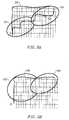
- Fig. 5AOne of the problems associated with employing a two- ended search algorithm based on A* in a grid-pattern region is illustrated by Fig. 5A.
- search regions 502 and 504tend toward the opposite route end point, the generated route tends to lie within a narrow region around the diagonal between S and D. This results in a route 506 with several turns as opposed to a more desirable route 508 with only one turn. Therefore, once the vehicle navigation system has determined that it is currently operating in a grid-pattern region, the search regions are loosened, as illustrated by search regions 502' and 504' of Fig. 5B. This has the effect of including routes with fewer turns within the search regions, including route 508.
- the route generation algorithmconsiders the costs associated with making turns, especially left turns, it becomes more likely that a route between S and D with fewer turns will be generated.
- the cost of making turns in grid-pattern regionsis increased, in order to increase the likelihood that a route with fewer turns will be generated.
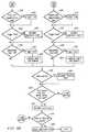
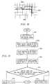
- Figs. 6A and 6Bcomprise a flowchart which illustrates the operation of a particular embodiment of the two-ended search algorithm illustrative of the present invention.
- the algorithmgenerates a route from a source location to a destination. Initially, the first and second current route nodes, i.e., the nodes in the forward and backward search path from which the algorithm is searching, are set to the source and destination, respectively, the iteration termination count its set to 500 and the route count is set to 4 (step 602).
- the route generation algorithmthen performs two searches substantially in parallel, i.e., from the source toward the destination and vice versa.
- Road segments emanating from the current route nodesare identified (steps 604 and 606), and heuristic costs are determined for each relative to the current route node of the other search (steps 608 and 610). In some embodiments, the heuristic costs are then weighted according to their respective road classes (steps 612 and 614), with the weights favouring higher class segments. The overall cost for each segment is then determined (steps 616 and 618) and the lowest cost segments for each of the searches are selected as the next segments in the respective routes (steps 620 and 622). The current route nodes are then updated to the end points of the selected segments (steps 624 and 626).
- Figs. 6A and 6Bshow an embodiment illustrative of the invention in which class 0 road segments are suppressed, i.e., ignored in subsequent searching, in each of the searches after 100 iterations of the two-ended search algorithm, and after class 1 road segments have already been encountered by each search (steps 628-654).
- class 0 segmentsmay be suppressed after fewer iterations, or alternatively, immediately after the first encounter of a class 1 segment.
- higher level segmentsmay be similarly suppressed after some number of iterations and upon encountering a still higher level segment, e.g., class 2.
- the systemdetermines whether any routes from the source to the destination have been generated by referring to the route count. If the route count is less than its initial value (step 656) , in this example, four, the iteration termination count is decremented (step 658) The system then determines whether the current route nodes for each end of the two-ended search coincide (step 660). If not, the algorithm performs another iteration beginning with steps 604 and 606. If the current route nodes coincide, i.e., a complete route has been generated, the route count is decremented (step 662). The system then determines whether the iteration termination count has reached zero (step 664). If not, the algorithm performs another iteration beginning with steps 604 and 606. If the iteration termination count has timed out, the system selects the lowest cost route from among all of the possible routes generated so far (step 666).
- the above-described route generation procedurebecomes a highly complicated and time consuming determination which results in delays in the communication of route instructions and upcoming manoeuvres to the user.
- the arrangements describedenable these delays to be avoided by selecting an intermediate destination close to the initial source location, generating a route to the intermediate location, and communicating the intermediate route while continuing to determine the route to the final destination.
- the featuremay be selected based on parameters such as the known relationship between the initial source location and the final destination and their geographical surroundings, e.g., both locations are in densely digitized urban areas separated by a sparsely digitized rural or highway area.
- intermediate destinationsare always determined, but a best intermediate destination is not chosen and the intermediate route is not communicated to the user unless the determination of the entire route takes longer than a programmable timeout period. This embodiment will be discussed in greater detail below. The method by which the intermediate destination is selected is described with reference to Fig. 7.
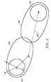
- Fig. 7shows a source location at point A and a final destination at point B.
- Point Agenerally represents the stationary starting position of the vehicle. However, if route generation is performed while the vehicle is moving, point A may be chosen at a position ahead of the current vehicle position. Parameters such as the vehicle's direction and speed may be taken into account for the determination of the source location in such a situation.
- Four possible intermediate routes 701, 703, 705, and 707are shown from point A to four different intermediate destinations 702, 704, 706, and 708, respectively.
- the intermediate destinations in this exampleare access points to highways 710 and 712. Highway access points are often chosen as intermediate destinations because they are easily identifiable, and the forward route generation from the highway access point becomes simplified for the reasons discussed above. Essentially, the intersection with any road which is of a higher category than the road of the source location may be selected as a possible intermediate destination.
- the navigation systemexplores several possible paths in the map database emanating from point A during a timeout interval, after the expiration of which, the best candidate for the intermediate destination is chosen.
- the timeout intervalmay be a multilevel interval. That is, the interval may be programmed to expire after 10 seconds if 3 or more candidates are found, and after 20 seconds if only one or two are found.
- the figureshows a situation in which four candidates for an intermediate destination have been found, i.e., highway access points 702, 704, 706, and 708.
- the systemcalculates an overall cost f(dest) for each possible intermediate destination by combining all of the segment and node costs, i.e., g(n) and g(k), for the route leading to that destination with the heuristic cost associated with that destination, i.e., h(dest) .
- the relationshipappears as follows: It will be understood that there are a number of different ways in which these values could be combined, or in which cost values may be assigned to derive an overall cost value for each intermediate route. The present invention is not limited to the specific embodiment described.
- Another method for selecting an intermediate destinationmay be used.
- the useris presented with a list of highways and highway access points within 10 miles of the source location.
- the usermay then select the desired highway and/or specific access point. This feature may be useful where, for example, the user knows that a certain highway is to be accessed, but requires route generation to get to that highway from the current location.
- the appropriate series of manoeuvresis communicated to the user via the system display.
- Thesegenerally include a series of screens, each of which communicates information regarding the next manoeuvre to be performed by the user, for example, the distance to the next manoeuvre, or the nature of the next manoeuvre (e.g., left turn) .
- the systemis providing the user with this information, the remainder of the route to the final destination and the corresponding manoeuvres are determined using the intermediate destination as the starting point. In this way, navigation is allowed to begin before the entire route is determined, thereby allowing the user to begin driving almost immediately.
- Manoeuvre generation and route guidancewill be discussed in more detail below.
- the vehicle navigation systemmay be programmed to wait until the expiration of a timeout period before selecting an intermediate destination. If the entire route to the final destination is determined within the timeout period, then the communication of an intermediate route is considered unnecessary and the intermediate destination is not selected. If, however, the entire route to the final destination is not complete before the expiration of the timeout interval, the system selects an intermediate destination and operates as described above. If the entire route is still not complete before the expiration of another timeout interval, the system may be programmed to determine another intermediate destination beyond the first intermediate destination. The selection of the next intermediate destination proceeds similarly to the selection of the first as described above. This process may be repeated until the remainder of the entire route has been determined.
- the systemmay be programmed to begin determining the next intermediate destination immediately if it is determined that the generation of the route to the final destination is not yet complete.
- the systemmay be programmed so that each successive intermediate route is fully determined and the corresponding manoeuvres communicated to the user only when the determination of the remainder of the entire route is not yet complete or requires more than a programmable timeout interval.
- the intermediate locationis a highway access point
- the manoeuvre on to the highwaycan be communicated to the user with a follow up instruction such as, for example, "Stay on the highway - Generating the rest of the route".
- a follow up instructionsuch as, for example, "Stay on the highway - Generating the rest of the route”.
- the direction of travelis deduced based on the direction from the highway access point to the final destination.
- a first intermediate destination 801is chosen before either of the access points 802 or 803 as shown in Fig. 8 so that either highway direction may be selected.
- there is chosen another intermediate destination beyond the first intermediate destinationthe route to which will be known by the time the first intermediate destination is reached.
- Another solution to the problem of arriving at the first intermediate destinationrelates to the determination of further intermediate destinations.
- the systemmay be programmed to determine another intermediate destination beyond the first intermediate destination. The selection of the next intermediate destination proceeds similarly to the selection of the first as described above. This process may be repeated until the remainder of the entire route has been determined.
- each intermediate routeis fully determined and the corresponding manoeuvres communicated to the user only when the determination of the remainder of the entire route requires more than a programmable timeout interval.
- Fig. 9is a flowchart 900 which describes the operation of a specific embodiment illustrative of the invention.
- the systemreceives a destination input by a user for the purpose of generating a route to the destination (step 902).
- the systemthen begins to determine the route from the vehicle's current position to the desired destination while simultaneously determining at least one intermediate destination (step 904).
- the systemdetermines a cost value for each intermediate destination (step 906). If a programmable time interval passes and the determination of the entire route from the initial position to the final destination is not complete (step 908), the system selects the intermediate destination having the lowest cost value as the best intermediate destination (step 910) and communicates the intermediate route to the user (step 912).
- the systemthen continues to determine a route to the final destination from the intermediate destination (step 914). If, on the other hand, the determination of the entire route is complete, the entire route is communicated to the user (step 916).
- step 918the system determines another group of intermediate destinations between the first intermediate destination and the final destination (step 920) and determines a cost value for each (step 922). If the route generation is not complete after a second programmable time interval (step 924), the system again selects the intermediate destination with the lowest cost value (step 926) and communicates the next intermediate route to the user (step 928). Steps 918-928 may be repeated until the remainder route to the final destination has been determined, at which point it is communicated to the user (step 930).
- Fig. 10is a flowchart 1000 for use in describing the selection of a plurality of intermediate routes according to a specific embodiment illustrative of the invention.
- the systemexplores possible routes emanating from one of the road segments directly connected to the vehicle's original position until a connecting road is encountered having a hierarchy level greater than the hierarchy level of the original position's road (step 1002).
- the systemdesignates the access point to the connecting road as one of the intermediate destinations (step 1004). Steps 1002 and 1004 are then repeated for each of the road segments emanating from the original position (step 1006).
- Fig. 11is a flowchart 1100 describing the determination of cost values for a plurality of intermediate destinations according to a specific embodiment illustrative of the invention.
- the systemcombines the segment and node costs for the road segments and nodes in one of the intermediate routes emanating from the vehicle's initial position, thereby generating a route cost for that intermediate route (step 1102).
- the systemdetermines a heuristic cost for the intermediate destination associated with the intermediate route (step 1104).
- the heuristic costcorresponds to the distance between the intermediate destination and the final destination.
- the systemthen combines the route cost with the heuristic cost and generates a cost value for the intermediate destination (step 1106). Steps 1102-1106 are then repeated for each of the intermediate destinations (step 1108).
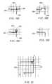
- Figs. 12A-Cillustrate some of the typical detours encountered when seaming two partial routes together.
- the first partial routeends at node 1202 which is beyond street 1204 upon which the second route eventually proceeds to the destination X.
- the second routemust "backtrack" to some extent resulting in an inefficiency which, from the user's perspective, may end up being rather inconvenient.
- Fig. 12A-Cillustrate some of the typical detours encountered when seaming two partial routes together.
- the first partial routeends at node 1202 which is beyond street 1204 upon which the second route eventually proceeds to the destination X.
- the second routemust "backtrack" to some extent resulting in an inefficiency which, from the user's perspective, may end up being rather inconvenient.
- second route 1206loops back over first route 1208 requiring the user to make three turns where only one should be required. That is, in the real world, the user would most likely prefer to execute the manoeuvre illustrated in Fig. 12D, i.e., simply turn left onto street 1204 without first proceeding to node 1202. In Fig. 12B, second route 1210 instead turns left but still requires two additional turns to get on to street 1204. Second route 1212 of Fig. 12C requires only two turns to get on to street 1204. However, one of these is a U-turn which, in some circumstances, may be extremely difficult or time consuming.
- first and second routesare generated (step 1502).
- first generated route 1402ends just beyond node N1 with segment S2
- second generated route 1404begins where route 1402 ends and proceeds with segments S3-S6 requiring a loop-back manoeuvre similar to the detour described with reference to Fig. 1 2A.
- step 1504determines whether the route directly from S1 to S6 is driveable (step 1506) If the routes do not intersect, or if the route from S1 to S6 is not navigable, an alternate seaming algorithm is performed (step 1508). If the routes intersect and S1-S6 is driveable, the system discards segments S2-S5 (step 1510). It will be understood that the u-turn scenario of Fig. 12C may also be used to illustrate this embodiment.
- first and second routes 1602 and 1604are generated (step 1702).
- the systemselects a source location S1 along first route 1602 preceding connection point X (step 1704).
- the systemselects a destination D1 along second route 1604 a short distance after connection point X (step 1706) and generates a partial route 1606 between source S1 and destination D1 (step 1708). If the cost associated with partial route 1606 is less than the cost associated with the portions of the first and second routes between source S1 and destination D1 (step 1710), partial route 1606 replaces those portions of the first and second route (step 1712). Otherwise, the original route is retained (step 1714).
- end points of partial route 1606, i.e., source S1 and destination D1represent new seaming points at which partial route 1606 is seamed with first and second routes 1602 and 1604, and that the above- described procedure may be employed in an iterative manner to optimize the overall route at each successive set of seaming points.
- Fig. 18Ashows a situation in which a first partial route 1802 has been generated from S onto freeway 1804 eastbound.
- the eastbound directionwas chosen because it is in the direction of the destination D.
- freeway 1804eventually turns toward the south, it turns out that the optimal route 1806 initially takes freeway 1804 westbound and then freeway 1808 north.
- the drivermust eventually exit eastbound freeway 1804 and reenter in the westbound direction to follow second partial route 1810 to D.
- Fig. 1 8Bis a magnified view of area 1812 of Fig. 1 8A which shows first partial route 1802 and the east and westbound entrances to freeway 1804.
- Fig. 1 8Cis a view of the same area with a truncated first partial route 1802' which allows the second partial route 1810'to enter freeway 1804 using the westbound entrance.
- the arrangement of this embodimentterminates partial route generation and backs up along the partial route until it reaches a road segment which precedes the point at which a decision must be made whether to proceed in one direction or the other. This prevents the situation shown in Fig. 1 8A where the user proceeds in the wrong direction.
- FIG. 19A and 19BAnother situation related to the termination of partial route generation is illustrated in Figs. 19A and 19B.
- search region 1902 in Fig. 1 9Awhen the A* search algorithm encounters a freeway 1904, it tends to expand search region 1902 in the direction of destination D along freeway 1904, resulting in a situation in which the use of freeway 1906 may be overlooked despite the fact that it lies on optimal route 1908.
- a stopis placed on the expansion of a partial route which reaches a freeway, but there is a continued look for alternate routes. This results in the expansion of a search region as illustrated by region 1902'of Fig. 19B. Because expansion along freeway 1904 is suspended, search region 1902' eventually reaches freeway 1906 by which a more efficient route is realized.
- each of the possible partial routes being explored by the route generation algorithmis expanded to a point where the combined g costs (representative of driving time) of the segments in at least one of the possible partial routes reaches a threshold value.
- the systemselects the partial route having the lowest h cost, i.e., the one with an endpoint closest to the destination.
- the systemwaits until each possible partial route is expanded to reach the g cost threshold before making the selection.
- the g cost threshold valueis either fixed or variable.
- the g cost thresholdis variable its value relates to the distance between the source and the destination. That is, the greater the distance between the source and the destination, the higher the g cost threshold will be set. This ensures that the driving time (i.e., g cost) associated with the generated partial route is sufficiently long for the complete route to the destination to be generated before the vehicle reaches the end of the partial route.
- the variable g cost thresholdalso ensures that the length of the selected partial route will not be overly long with respect to the complete route.
- the longer the partial route is with respect to the complete routethe greater the chance that the optimal route is not being generated This often results in undesirable backtracking manoeuvres, such as u-turns or exiting and reentering freeways, being included in the complete route. Maintaining the partial route in proper proportion to the complete route reduces the risk of such undesirable occurrences.
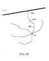
- the g cost thresholdis set high enough to ensure that at least one of the partial route candidates includes the nearest highway entrance. It will be understood, however, that this goal may, in some instances, conflict with the goal of maintaining the length of the partial route in proper proportion to the distance between the source and the destination. Therefore, in one particular embodiment illustrative of the invention this conflict is resolved in the following manner as described with reference to Fig. 20. Initially, the g cost threshold is set such that the closest highway entrance (at node 2002) is included in at least one partial route candidate. The search algorithm then expands the various partial routes until the highway entrance is reached.
- the systembacks up the end point of the partial route to a point 2006 where its g cost does not exceed the distance-based threshold. This makes it more likely that the complete route will be closer to the optimal route and less likely that the driver will do something like enter the highway going the wrong direction.
- the useris allowed to specify certain parameters which affect the operation of the route generation algorithm.
- the useris allowed to specify a preference regarding the use of freeways. That is, the user may specify that the algorithm should make the most or the least use of freeways in generating the route.
- the algorithmaccommodates the user's preference by manipulating the g costs associated with the freeway segments. So, for example, if the user specifies that the algorithm should make the least use of freeways, the g costs associated with freeway segments are increased to make them less desirable candidates for inclusion in the generated route.
- the g costs employed by the route generation algorithmare not always the actual g costs for the corresponding road segments.
- the systemkeeps track of the actual g costs of the segments in the partial route candidate in parallel with the manipulation of the g costs for implementing options such as the most/least use of freeways option.
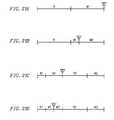
- Figs. 21A-Dare a series of time lines which illustrate the manner in which manoeuvre instructions associated with generated routes may be generated and communicated to a driver.
- the entire routeis generated (as represented by R)
- the generation of the manoeuvre instructions corresponding to the generated route(as represented by M) .
- Gfor "guidance"
- the point at which route guidance beginsmay be advanced significantly.
- the systemgenerates the entire route (R), followed by the generation of the first several manoeuvre instructions (as represented by M1), followed by the generation of the remainder of the manoeuvre instructions (as represented by M2) .
- Route guidance (G)may thus begin after the first several instructions have been generated; well in advance of the point at which all of the instructions have been generated. In many route generation scenarios, this represents a substantial improvement. Unfortunately, the undesirable delay represented by the route generation remains.
- a third embodiment illustrative of the inventioncombines incremental manoeuvre generation with incremental route generation as described above.
- Fig. 21Cshows a time line in which the route generation is divided into two partial route generations (as represented by R1 and R2) .
- the manoeuvres corresponding to the first partial routeare generated immediately after the first partial route is generated (as represented by M1) and route guidance begins immediately thereafter.
- the manoeuvres corresponding to the remainder of the routeare generated (as represented by M2) after the second partial route has been generated.
- FIG. 21Droute generation is again divided into two partial route generations (R1 and R2). However, instead of waiting until all of the manoeuvre instructions corresponding to the first partial route are generated before beginning route guidance, only a portion of these are generated (as represented by M1 at which time route guidance begins (G) . The remainder of the manoeuvre instructions is then generated (M2) followed by the second partial route generation (R2) and the generation of the remainder of the manoeuvre instructions which correspond to the second partial route (M2) . Again, comparison of the time lines of Figs. 21C and 21D reveal that another improvement is realized.
- the number of “incremental” manoeuvre instructions generatedmay vary according to the different embodiments described above. “Incremental” manoeuvre instructions refers to the manoeuvre instructions after generation of which route guidance begins. For example, in the embodiment of Fig. 21B, enough “incremental” manoeuvre instructions are generated (M1) to allow the remainder of the manoeuvre instructions to be generated (M2) before the driver actually executes all of the first set of manoeuvres. Such a number may be established, for example, with reference to the distance between the source and destination. Alternatively, the number of "incremental” manoeuvre instructions may be determined by relating the g cost corresponding to the part of the route encompassed by the "incremental” manoeuvre instructions to the time required to generate the remainder of the instructions. In the embodiment of Fig.
- the number of "incremental” manoeuvre instructions generated (M1)directly relates to the number of manoeuvres in the first partial route.
- the number of "incremental" manoeuvre instructions generated (M1)may relate to the time required for generation of the remainder of the instructions corresponding to the first partial route (M2). That is, the g cost associated with the portion of the first partial route corresponding to the "incremental” manoeuvre instructions should be such that the remainder of the instructions corresponding to the first partial route may be generated before the driver executes all of the "incremental" manoeuvres.
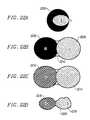
- Fig. 22Ashows a comparison between the search region shapes emanating from a source location S toward a destination D for a single-ended algorithm, i.e., circular region 2202, and an A* search algorithm in which road segments are assigned heuristic costs, i.e., elliptical search region 2204.
- Fig. 22Ashows a comparison between the search region shapes emanating from a source location S toward a destination D for a single-ended algorithm, i.e., circular region 2202, and an A* search algorithm in which road segments are assigned heuristic costs, i.e., elliptical search region 2204.
- FIG. 22Bshows a two-ended search with search regions 2206 and 2208 combining to cover the area enclosed by region 2210.
- Fig. 22Cshows a two-ended search algorithm in which road segments of at least one rank have been suppressed from both ends of the search as represented by cross-hatched search regions 2212 and 2214.
- Fig. 22Dshows a two-ended search algorithm according to a specific embodiment of the invention in which the segment rank suppression and heuristic cost features of the present invention have been combined resulting in a search area 2220, i.e., regions 2216 and 2218, which is considerably smaller than and less computationally intense than previous route generation methods.
Landscapes
- Engineering & Computer Science (AREA)
- Radar, Positioning & Navigation (AREA)
- Remote Sensing (AREA)
- Automation & Control Theory (AREA)
- Physics & Mathematics (AREA)
- General Physics & Mathematics (AREA)
- Navigation (AREA)
Abstract
Description

Claims (30)
- A method for determining a route from a first location to asecond location using a vehicle navigation system, the method including thesteps ofsearching a map database for a first number of iterationsthereby generating a first route candidate,after generation of the first route candidate, terminating thesearching step after a second number of additional iterations, andselecting a best route candidate as the route.
- A method as claimed in claim 1 wherein the secondnumber is determined with reference to a distance between the first andsecond locations.
- A method as claimed in claim 1 wherein the secondnumber is determined with reference to the first number.
- A method as claimed in claim 1 further including, wherethe second number of additional iterations has not yet occurred, the step ofterminating the searching step after a second number of route candidateshas been generated.
- A method as claimed in claim 1 wherein the secondnumber is reduced by a bonus amount for each additional route candidategenerated after the generation of the first route candidate.
- A method as claimed in claim 1 wherein the searching step includes searching the map database beginning from the first location.
- A method as claimed in claim 6 wherein the searchingstep also includes searching the map database beginning from the secondlocation.
- A method for determining a route from a first location to asecond location using a vehicle navigation system, the method including thesteps ofsearching a map database for a plurality of iterations therebygenerating at least one route candidate,during the searching step, identifying a first road segmenthaving a first rank associated therewith,in response to the identifying step, excluding from subsequentiterations of the searching step all other road segments having ranksassociated therewith below the first rank, andselecting a best route candidate as the route.
- A method as claimed in claim 8 further including the stepof executing a first number of iterations of the searching step after the firstroad segment is identified and before performing the excluding step.
- A method as claimed in claim 9 wherein the first numberis determined with reference to a distance between the first and secondlocations.
- A method for determining a route using a vehiclenavigation system, the route including a plurality of contiguous roadsegments, the method including the steps ofexpanding a search region to search the map database for thecontiguous road segments, the search region having at least one parameterassociated therewith,determining whether the search region encompasses aportion of the map database characterized by a grid pattern, andwhere the search region encompasses the portion of the mapdatabase characterized by the grid pattern, manipulating the parameterassociated with the search region.
- A method for connecting a first route generated by avehicle navigation system to a second route generated by the vehiclenavigation system, the method including the steps ofgenerating the first and second routes, the first and secondroutes being connected at a connection point forming a third route,generating a fourth route from a source point on the first routenear the connection point to a destination point on the second route near theconnection point, andreplacing a portion of the third route between the source anddestination points with the fourth route.
- A method for connecting a first route generated by avehicle navigation system to a second route generated by the vehiclenavigation system, the method including the steps ofgenerating the first and second routes,removing unnecessary portions of the third route coupled to the intersectionpoint.connecting the first and second routes at a connectionpoint forming a third route,determining whether the first and second routesintersect at an intersection point, andwhere the first and second routes intersect,
- A method for generating a partial route in a vehiclenavigation system prior to the generation of a complete route between firstand second locations, the method including the steps ofsearching a map database to generate a plurality of partialroute candidates, each of the partial route candidates having a travel costand a heuristic cost associated therewith,terminating the searching step where the travel costassociated with at least one of the partial route candidates reaches a firstthreshold value, andselecting as the partial route one of the partial routecandidates having the lowest heuristic cost associated therewith.
- A method as claimed in claim 14 wherein the firstthreshold value is determined with reference to the distance between thefirst and second locations.
- A method as claimed in claim 14 wherein the terminatingstep includes terminating the searching step where the travel costsassociated with all of the partial route candidates reach the first thresholdvalue.
- A method as claimed in claim 14 wherein the firstthreshold value is set such that a limited access road entrance is included inat least one of the partial route candidates.
- A method as claimed in claim 17 wherein total costs associated with limited access roads are reduced to favour use of the limitedaccess roads in route generation, the total cost including the sum of traveland heuristic costs associated with the limited access roads.
- A method as claimed in claim 17 wherein a secondthreshold value is determined with reference to the distance between thefirst and second locations, and the method further includes the step of,where the second threshold value is less than the first threshold value,truncating the at least one of the partial route candidates such that the travelcost associated therewith does not exceed the second threshold value.
- A method as claimed in claim 14 wherein the vehiclenavigation system operates in a mode in which selected travel costs areadjusted to generate adjusted travel costs for route generation purposes, themethod further including the step of, while the vehicle navigation system isoperating in the mode, keeping track of the selected travel costs for partialroute termination purposes.
- A method as claimed in claim 20 wherein the modeincludes a freeway mode in which the vehicle navigation system decreasestravel costs associated with freeways to favour the use of freeways for routegeneration.
- A method as claimed in claim 20 wherein the modeincludes a surface street mode in which the vehicle navigation systemincreases travel costs associated with freeways to favour the use of surfacestreets for route generation.
- A method for terminating partial route generation in avehicle navigation system, the partial route including a plurality of contiguousroad segments stored in a map database, the method including the steps ofsearching the map database for the contiguous roadsegments,terminating partial route generation upon selecting as part ofthe partial route a first road segment having access to a limited access road,the limited access road having two directions associated therewith,identifying a second road segment in the partial route fromwhich access to both directions of the limited access road is possible, andremoving any of the contiguous road segments in the partialroute beyond the second road segment.
- A method for terminating partial route generation in avehicle navigation system, the partial route including a plurality of contiguousroad segments stored in a map database, the method including the steps ofexpanding a search region to search the map database for thecontiguous road segments,upon selecting as part of the partial route a first road segmentincluding a portion of a first limited access road, terminating the expansion ofthe search region along the first limited access road, andcontinuing the expansion of the search region in at least oneother direction until a second limited access road is encountered.
- A method for providing route guidance using a vehiclenavigation system, including the steps ofgenerating a route from a first location to a second location,generating a first plurality of manoeuvre instructionscorresponding to a first portion of the route,communicating the first plurality of manoeuvre instructions viaa user interface, andgenerating a second plurality of manoeuvre instructionscorresponding to a remainder of the route after the communication of thefirst plurality of manoeuvre instructions begins.
- A method as claimed in claim 25 wherein the routeincludes a first partial route from the first location to an intermediate locationand a second partial route from the intermediate location to the secondlocation, the first partial route including the first portion of the route, andwherein the generation of the first plurality of manoeuvre instructions occursbefore the generation of the second partial route begins.
- A method for determining a route from a first location to asecond location using a vehicle navigation system, the method including thesteps ofsearching a map database thereby generating at least oneroute candidate, the map database comprising a plurality of road segments,during the searching step, dynamically adjusting a costassociated with each of a plurality of selected road segments to favour theinclusion of a particular type of road segment in the route, andselecting a best route candidate as the route.
- A method as claimed in claim 27 wherein the costassociated with each of the selected road segments includes a heuristic costwhich relates to the distance between the selected road segment and thesecond location, and a travel cost which relates to the time required totraverse the selected road segment.
- A method as claimed in claim 28 wherein the step ofdynamically adjusting the cost includes adjusting the heuristic costsassociated with the selected road segments.
- A method as claimed in claim 28 wherein the step ofdynamically adjusting the cost includes reducing the cost associated witheach of the selected road segments by a discount value, the discount valuefor each selected road segment being determined with reference to thetravel cost associated therewith.
Applications Claiming Priority (2)
| Application Number | Priority Date | Filing Date | Title |
|---|---|---|---|
| US784204 | 1997-01-15 | ||
| US08/784,204US5938720A (en) | 1995-02-09 | 1997-01-15 | Route generation in a vehicle navigation system |
Publications (3)
| Publication Number | Publication Date |
|---|---|
| EP0854353A2true EP0854353A2 (en) | 1998-07-22 |
| EP0854353A3 EP0854353A3 (en) | 2000-04-26 |
| EP0854353B1 EP0854353B1 (en) | 2004-09-01 |
Family
ID=25131672
Family Applications (1)
| Application Number | Title | Priority Date | Filing Date |
|---|---|---|---|
| EP98300263AExpired - LifetimeEP0854353B1 (en) | 1997-01-15 | 1998-01-15 | Route determination in a vehicle navigation system |
Country Status (5)
| Country | Link |
|---|---|
| US (1) | US5938720A (en) |
| EP (1) | EP0854353B1 (en) |
| JP (1) | JP3078520B2 (en) |
| CA (1) | CA2224745C (en) |
| DE (1) | DE69825924T2 (en) |
Cited By (17)
| Publication number | Priority date | Publication date | Assignee | Title |
|---|---|---|---|---|
| EP0978706A3 (en)* | 1998-08-04 | 2000-08-30 | Ford Global Technologies, Inc., A subsidiary of Ford Motor Company | A method and system for generating a navigation route |
| WO2000079219A1 (en)* | 1999-06-22 | 2000-12-28 | Robert Bosch Gmbh | Method and device for determining a route from a starting location to a final destination |
| EP1149344A4 (en)* | 1998-12-10 | 2002-05-15 | Tele Atlas North America Inc | Shortcut generator |
| FR2818414A1 (en)* | 2000-12-20 | 2002-06-21 | Webraska Mobile Technologies S | Method for determining the minimum cost between two points on a road network in which route calculation starts from both start and end point at the same time to reduce server calculation time |
| WO2003058170A1 (en)* | 2002-01-09 | 2003-07-17 | Webraska Mobile Technologies | Method and device for determining the minimal cost path between two points in a road network |
| US7035856B1 (en)* | 2000-09-28 | 2006-04-25 | Nobuyoshi Morimoto | System and method for tracking and routing shipped items |
| WO2006042687A1 (en)* | 2004-10-18 | 2006-04-27 | Societe De Technologie Michelin | Route calculation device and method with progressive elimination of data corresponding to the road network |
| EP1115101A4 (en)* | 1999-05-25 | 2006-05-17 | Mitsubishi Electric Corp | CARD MANUFACTURING DEVICE |
| EP1939590A1 (en)* | 2006-12-29 | 2008-07-02 | MAGNETI MARELLI SISTEMI ELETTRONICI S.p.A. | A method of calculating an optimal path between a starting point and a destination point, and constrained to pass through an intermediate waypoint, a navigation system and a corresponding computer program product |
| US7428525B1 (en) | 1999-11-12 | 2008-09-23 | Tele Atlas North America, Inc. | Virtual street addressing radius |
| WO2009006351A1 (en)* | 2007-06-29 | 2009-01-08 | Tele Atlas North America, Inc. | System and method for determining routing point placement for aiding in encoding and decoding a path |
| EP2075537A2 (en) | 2007-12-25 | 2009-07-01 | Aisin Aw Co., Ltd. | Navigation apparatus and program |
| CN103971008A (en)* | 2014-05-19 | 2014-08-06 | 浪潮电子信息产业股份有限公司 | Improved heuristic A * algorithm |
| EP2310971A4 (en)* | 2008-06-24 | 2015-11-11 | Tomtom North America Inc | Methods and systems for dynamically adaptive road network hierarchy and routing |
| EP2955482A1 (en)* | 2014-06-10 | 2015-12-16 | Sikorsky Aircraft Corporation | Aircraft motion planning method |
| CN106371439A (en)* | 2016-09-13 | 2017-02-01 | 同济大学 | Unified automatic driving transverse planning method and system |
| WO2020154670A1 (en)* | 2019-01-25 | 2020-07-30 | Uatc, Llc | Vehicle routing with local and general routes |
Families Citing this family (131)
| Publication number | Priority date | Publication date | Assignee | Title |
|---|---|---|---|---|
| US6249740B1 (en)* | 1998-01-21 | 2001-06-19 | Kabushikikaisha Equos Research | Communications navigation system, and navigation base apparatus and vehicle navigation apparatus both used in the navigation system |
| JPH11261626A (en)* | 1998-03-09 | 1999-09-24 | Mitsubishi Electric Corp | Data delivery system and data delivery method |
| US6192314B1 (en) | 1998-03-25 | 2001-02-20 | Navigation Technologies Corp. | Method and system for route calculation in a navigation application |
| US6539080B1 (en) | 1998-07-14 | 2003-03-25 | Ameritech Corporation | Method and system for providing quick directions |
| DE19836485A1 (en) | 1998-08-12 | 2000-02-17 | Bosch Gmbh Robert | Method for determining a route from a starting point to a destination on a route network |
| DE19908941A1 (en)* | 1999-03-02 | 2000-09-07 | Bosch Gmbh Robert | Navigation method and navigation system for determining a route from a starting point to a destination for a means of transportation |
| US6222485B1 (en)* | 1999-05-20 | 2001-04-24 | Garmin Corporation | Use of desired orientation in automotive navigation equipment |
| US6266615B1 (en) | 1999-09-27 | 2001-07-24 | Televigation, Inc. | Method and system for an interactive and real-time distributed navigation system |
| US6654683B2 (en) | 1999-09-27 | 2003-11-25 | Jin Haiping | Method and system for real-time navigation using mobile telephones |
| US6564224B1 (en)* | 1999-12-06 | 2003-05-13 | Kivera, Inc. | Method and apparatus for merging multiple road map databases |
| US6615131B1 (en) | 1999-12-21 | 2003-09-02 | Televigation, Inc. | Method and system for an efficient operating environment in a real-time navigation system |
| US6405123B1 (en) | 1999-12-21 | 2002-06-11 | Televigation, Inc. | Method and system for an efficient operating environment in a real-time navigation system |
| JP2001216286A (en)* | 2000-02-03 | 2001-08-10 | Sony Corp | Information processing method and information processor |
| GB0002985D0 (en)* | 2000-02-09 | 2000-03-29 | Travelfusion Limited | Integrated journey planner |
| KR100770644B1 (en) | 2000-02-16 | 2007-10-29 | 텔레비게이션 인크 | Method and system for efficient operating environment in real time navigation system |
| WO2001063456A2 (en) | 2000-02-22 | 2001-08-30 | Pointserve, Inc. | Data formats and usage for massive point to point route calculation |
| DE10012441C2 (en)* | 2000-03-15 | 2002-03-14 | Bosch Gmbh Robert | Method for entering a destination on a navigation device |
| US6456935B1 (en) | 2000-03-28 | 2002-09-24 | Horizon Navigation, Inc. | Voice guidance intonation in a vehicle navigation system |
| US6278939B1 (en)* | 2000-07-24 | 2001-08-21 | Navigation Technologies Corp. | Method and system for providing data from a remotely located geographic database for use in navigation system units |
| ES2377638T3 (en)* | 2001-01-24 | 2012-03-29 | Telenav, Inc. | Real-time navigation system for mobile environment |
| US6456931B1 (en)* | 2001-03-07 | 2002-09-24 | Visteon Technologies, Llc | Indicating directions to destination and intermediate locations in vehicle navigation systems |
| US20020169543A1 (en)* | 2001-04-02 | 2002-11-14 | Blewitt Ronald L. | Long distance routing |
| JP4707877B2 (en)* | 2001-06-11 | 2011-06-22 | パイオニア株式会社 | Drive candidate location presentation apparatus and method, navigation apparatus, and computer program |
| DE10128517A1 (en)* | 2001-06-13 | 2003-01-02 | Vodafone Ag | Method for generating navigation data for route guidance and navigation system |
| DE10162359B4 (en)* | 2001-12-18 | 2012-10-31 | Robert Bosch Gmbh | Method for providing route data for a navigation device |
| US7221287B2 (en) | 2002-03-05 | 2007-05-22 | Triangle Software Llc | Three-dimensional traffic report |
| US20040243533A1 (en)* | 2002-04-08 | 2004-12-02 | Wsi Corporation | Method for interactively creating real-time visualizations of traffic information |
| US20040034467A1 (en)* | 2002-08-09 | 2004-02-19 | Paul Sampedro | System and method for determining and employing road network traffic status |
| US20040044465A1 (en)* | 2002-08-29 | 2004-03-04 | Nesbitt David W. | Automated route determination based on day of route traversal |
| US20040052239A1 (en)* | 2002-08-29 | 2004-03-18 | Nesbitt David W. | Automated route determination |
| US7133771B1 (en)* | 2002-08-29 | 2006-11-07 | America Online, Inc. | Automated route determination to avoid a particular maneuver |
| JP2004108803A (en)* | 2002-09-13 | 2004-04-08 | Pioneer Electronic Corp | Navigation terminal, navigation system, its program, and travel guidance method |
| US6807483B1 (en) | 2002-10-11 | 2004-10-19 | Televigation, Inc. | Method and system for prediction-based distributed navigation |
| JP3722108B2 (en)* | 2002-11-01 | 2005-11-30 | 株式会社デンソー | Car navigation system |
| US7321824B1 (en) | 2002-12-30 | 2008-01-22 | Aol Llc | Presenting a travel route using more than one presentation style |
| US7818116B1 (en) | 2002-12-30 | 2010-10-19 | Mapquest, Inc. | Presenting a travel route in a ground-based vehicle |
| US7474960B1 (en) | 2002-12-30 | 2009-01-06 | Mapquest, Inc. | Presenting a travel route |
| WO2005013063A2 (en) | 2003-07-25 | 2005-02-10 | Landsonar, Inc. | System and method for determining recommended departure time |
| US7065448B1 (en) | 2003-10-01 | 2006-06-20 | America Online, Inc. | Presenting driving directions |
| KR101128921B1 (en) | 2004-07-09 | 2012-03-27 | 테직 커뮤니케이션 인코포레이티드 | Disambiguating ambiguous characters |
| JP4130441B2 (en) | 2004-07-16 | 2008-08-06 | 三菱電機株式会社 | Map information processing device |
| DE102004044968A1 (en)* | 2004-09-16 | 2006-04-06 | Siemens Ag | Navigation system and method for determining a route |
| FR2876819A1 (en)* | 2004-10-18 | 2006-04-21 | Michelin Soc Tech | METHOD FOR DETERMINING ROUTE BASED ON SINUOSITY INDEX |
| US20060095171A1 (en)* | 2004-11-02 | 2006-05-04 | Whittaker William L | Methods, devices and systems for high-speed autonomous vehicle and high-speed autonomous vehicle |
| DE102004061636A1 (en)* | 2004-12-17 | 2006-07-06 | Eads Deutschland Gmbh | Method for determining optimized tracks of a vehicle intended for implementation in a computer system, and system for determining optimized target tracks |
| US7689349B1 (en) | 2004-12-23 | 2010-03-30 | Aol Llc | Automatic determination of a surrogate origin for personalized routing |
| US7395153B1 (en) | 2004-12-23 | 2008-07-01 | Aol Llc | Reducing driving directions |
| US7908080B2 (en) | 2004-12-31 | 2011-03-15 | Google Inc. | Transportation routing |
| US20060161337A1 (en)* | 2005-01-19 | 2006-07-20 | Ping-Chung Ng | Route planning process |
| FR2881862B1 (en)* | 2005-02-07 | 2007-04-13 | Michelin Soc Tech | METHOD AND DEVICE FOR DETERMINING ROUTE WITH POINTS OF INTEREST |
| US7627423B2 (en)* | 2005-03-10 | 2009-12-01 | Wright Ventures, Llc | Route based on distance |
| US7945383B2 (en)* | 2005-04-20 | 2011-05-17 | Alpine Electronics, Inc | Route determination method and apparatus for navigation system |
| JP4581912B2 (en)* | 2005-08-24 | 2010-11-17 | 株式会社デンソー | Navigation device |
| DE102005049769A1 (en)* | 2005-10-18 | 2007-04-26 | Robert Bosch Gmbh | An information processing system and method for processing information relating to successive units |
| US7761350B1 (en)* | 2006-04-26 | 2010-07-20 | Aol Inc. | Biasing of search result clustering to ensure more effective point of interest (POI) targeting |
| US7920965B1 (en)* | 2006-05-05 | 2011-04-05 | Mapquest, Inc. | Identifying a route configured to travel through multiple points of interest |
| US20080097688A1 (en)* | 2006-06-27 | 2008-04-24 | Microsoft Corporation | Route generation based upon activity criteria |
| US7610151B2 (en)* | 2006-06-27 | 2009-10-27 | Microsoft Corporation | Collaborative route planning for generating personalized and context-sensitive routing recommendations |
| US8793066B2 (en)* | 2006-06-27 | 2014-07-29 | Microsoft Corporation | Route monetization |
| US8392111B2 (en)* | 2006-08-04 | 2013-03-05 | Samsung Electronics Co., Ltd. | Navigation method, medium, and system |
| GB2443472A (en)* | 2006-10-30 | 2008-05-07 | Cotares Ltd | Method of generating routes |
| US8745041B1 (en)* | 2006-12-12 | 2014-06-03 | Google Inc. | Ranking of geographic information |
| US8095303B1 (en) | 2006-12-29 | 2012-01-10 | Mapquest, Inc. | Identifying a route configured to travel through multiple points of interest |
| US9037409B2 (en)* | 2007-05-04 | 2015-05-19 | Ian Cummings | Navigator database search methods |
| US8000892B2 (en)* | 2007-06-12 | 2011-08-16 | Campus Destinations, Inc. | Pedestrian mapping system |
| JP4345897B2 (en)* | 2007-07-05 | 2009-10-14 | 本田技研工業株式会社 | Navigation device, navigation system |
| DE102007043037A1 (en)* | 2007-09-11 | 2009-04-16 | Navigon Ag | Method and navigation device for determining a route |
| US8090532B2 (en)* | 2007-12-14 | 2012-01-03 | Microsoft Corporation | Pedestrian route production |
| US20090157540A1 (en)* | 2007-12-14 | 2009-06-18 | Microsoft Corporation | Destination auctioned through business of interest |
| US8473198B2 (en)* | 2007-12-14 | 2013-06-25 | Microsoft Corporation | Additional content based on intended travel destination |
| US20090157498A1 (en)* | 2007-12-14 | 2009-06-18 | Microsoft Corporation | Generational intelligent navigation synchronization or update |
| US20090157312A1 (en)* | 2007-12-14 | 2009-06-18 | Microsoft Corporation | Social network based routes |
| US20090157499A1 (en)* | 2007-12-14 | 2009-06-18 | Microsoft Corporation | Automatic splices for targeted advertisements |
| US8428859B2 (en)* | 2007-12-14 | 2013-04-23 | Microsoft Corporation | Federated route production |
| US8060297B2 (en)* | 2007-12-14 | 2011-11-15 | Microsoft Corporation | Route transfer between devices |
| JP5239328B2 (en)* | 2007-12-21 | 2013-07-17 | ソニー株式会社 | Information processing apparatus and touch motion recognition method |
| US8676489B2 (en)* | 2008-02-07 | 2014-03-18 | Microsoft Corporation | Positioning map views to show more optimal route information |
| US20090210142A1 (en)* | 2008-02-19 | 2009-08-20 | Microsoft Corporation | Safe route configuration |
| US20090210276A1 (en)* | 2008-02-19 | 2009-08-20 | Microsoft Corporation | Ad hoc and opportunistic transportation services |
| US20090210242A1 (en)* | 2008-02-19 | 2009-08-20 | Microsoft Corporation | Load balance payment |
| US8793065B2 (en)* | 2008-02-19 | 2014-07-29 | Microsoft Corporation | Route-based activity planner |
| DE102008027957B4 (en)* | 2008-03-11 | 2012-01-12 | Navigon Ag | Routing method for calculating a route |
| US20100021013A1 (en)* | 2008-07-25 | 2010-01-28 | Gale William N | Open area maps with guidance |
| US8374780B2 (en)* | 2008-07-25 | 2013-02-12 | Navteq B.V. | Open area maps with restriction content |
| US8417446B2 (en)* | 2008-07-25 | 2013-04-09 | Navteq B.V. | Link-node maps based on open area maps |
| US8339417B2 (en)* | 2008-07-25 | 2012-12-25 | Navteq B.V. | Open area maps based on vector graphics format images |
| US8099237B2 (en) | 2008-07-25 | 2012-01-17 | Navteq North America, Llc | Open area maps |
| US8229176B2 (en) | 2008-07-25 | 2012-07-24 | Navteq B.V. | End user image open area maps |
| US8825387B2 (en)* | 2008-07-25 | 2014-09-02 | Navteq B.V. | Positioning open area maps |
| US20100023251A1 (en)* | 2008-07-25 | 2010-01-28 | Gale William N | Cost based open area maps |
| US8219317B2 (en)* | 2008-09-22 | 2012-07-10 | Mitac International Corporation | Route navigation via a proximity point |
| US20100121564A1 (en)* | 2008-10-31 | 2010-05-13 | Hitachi Automotive Systems, Ltd. | Remote guide system, remote guide method and remote guide device |
| US8219316B2 (en)* | 2008-11-14 | 2012-07-10 | Google Inc. | System and method for storing and providing routes |
| TW201022633A (en)* | 2008-12-11 | 2010-06-16 | Mitac Int Corp | Route planning methods and systems, and machine readable medium and computer program products thereof |
| US9250094B2 (en) | 2009-02-03 | 2016-02-02 | Telenav, Inc. | Navigation system with path prediction and method of operation thereof |
| JP5393195B2 (en)* | 2009-02-26 | 2014-01-22 | アルパイン株式会社 | Navigation device and route search method |
| US9046924B2 (en) | 2009-03-04 | 2015-06-02 | Pelmorex Canada Inc. | Gesture based interaction with traffic data |
| US8982116B2 (en) | 2009-03-04 | 2015-03-17 | Pelmorex Canada Inc. | Touch screen based interaction with traffic data |
| US8619072B2 (en) | 2009-03-04 | 2013-12-31 | Triangle Software Llc | Controlling a three-dimensional virtual broadcast presentation |
| CN102859323A (en) | 2009-11-24 | 2013-01-02 | 特洛吉斯有限公司 | Vehicle route selection based on energy usage |
| GB2487701B (en)* | 2009-12-18 | 2013-01-16 | Ibm | Cost evaluation system, method and program |
| US9123243B2 (en)* | 2010-01-15 | 2015-09-01 | Toyota Jidosha Kabushiki Kaisha | Vehicle control device |
| US8700327B2 (en)* | 2010-04-27 | 2014-04-15 | Honda Motor Co., Ltd. | Method of determining routes for use in navigation |
| US8583363B2 (en)* | 2010-05-26 | 2013-11-12 | Microsoft Corporation | Determining alternative routes |
| DE102010030715B4 (en)* | 2010-06-30 | 2018-01-18 | Preh Car Connect Gmbh | Method and device for the efficient calculation of routes |
| US8374792B2 (en)* | 2010-07-30 | 2013-02-12 | Primordial Inc. | System and method for multi-resolution routing |
| US8718910B2 (en) | 2010-11-14 | 2014-05-06 | Pelmorex Canada Inc. | Crowd sourced traffic reporting |
| US8725396B2 (en) | 2011-05-18 | 2014-05-13 | Pelmorex Canada Inc. | System for providing traffic data and driving efficiency data |
| EP2557395A1 (en)* | 2011-08-11 | 2013-02-13 | Harman Becker Automotive Systems GmbH | Method and system for navigation |
| WO2013113029A1 (en) | 2012-01-27 | 2013-08-01 | Triangle Software, Llc | Estimating time travel distributions on signalized arterials |
| JP5895630B2 (en)* | 2012-03-15 | 2016-03-30 | 富士通株式会社 | Route search method, route search device, and program |
| US9958272B2 (en)* | 2012-08-10 | 2018-05-01 | Telogis, Inc. | Real-time computation of vehicle service routes |
| US10223909B2 (en) | 2012-10-18 | 2019-03-05 | Uber Technologies, Inc. | Estimating time travel distributions on signalized arterials |
| US9811797B2 (en) | 2013-03-15 | 2017-11-07 | Sap Se | Transportation connection cache for dynamic network and route determination |
| DE102013211602A1 (en) | 2013-06-20 | 2014-12-24 | Bayerische Motoren Werke Aktiengesellschaft | Method and device for determining a route |
| CN104426767B (en)* | 2013-08-28 | 2019-08-02 | Sap欧洲公司 | The method and system of Route Selection based on route distance and capacity |
| KR101567151B1 (en)* | 2013-12-03 | 2015-11-13 | 현대자동차주식회사 | A route searching method of navigation and the apparatus for this |
| US9413707B2 (en) | 2014-04-11 | 2016-08-09 | ACR Development, Inc. | Automated user task management |
| US8942727B1 (en) | 2014-04-11 | 2015-01-27 | ACR Development, Inc. | User Location Tracking |
| CN104978420B (en)* | 2015-06-30 | 2018-09-07 | 百度在线网络技术(北京)有限公司 | Traffic route matching process and device |
| US10274331B2 (en) | 2016-09-16 | 2019-04-30 | Polaris Industries Inc. | Device and method for improving route planning computing devices |
| US10274327B2 (en) | 2016-12-29 | 2019-04-30 | Fastzach, Llc | Configurable routes |
| US10970291B2 (en)* | 2018-08-10 | 2021-04-06 | MachineVantage, Inc. | Detecting topical similarities in knowledge databases |
| US11604073B1 (en) | 2018-09-24 | 2023-03-14 | Apple Inc. | Route guidance system |
| US11358585B2 (en) | 2019-01-04 | 2022-06-14 | Delphi Technologies Ip Limited | System and method for torque split arbitration |
| US11137258B2 (en)* | 2019-01-07 | 2021-10-05 | Servicenow, Inc. | Systems and methods for comprehensive routing |
| US11781875B2 (en)* | 2019-08-21 | 2023-10-10 | Toyota Motor Engineering & Manufacturing North America, Inc. | Apparatus and method for forming and analyzing connected roads |
| US11761772B2 (en)* | 2019-10-28 | 2023-09-19 | Here Global B.V. | Method and apparatus for providing speculative navigation routing in incomplete offline maps |
| CN112669624B (en)* | 2021-01-22 | 2022-08-12 | 胡渐佳 | Traffic intersection signal control method and system based on intelligent navigation |
| JP2022152476A (en)* | 2021-03-29 | 2022-10-12 | セコム株式会社 | Route search device, route search method and route search program |
| PL247549B1 (en)* | 2023-06-06 | 2025-07-28 | Politechnika Krakowska Im Tadeusza Kosciuszki | Fixing assembly |
Family Cites Families (58)
| Publication number | Priority date | Publication date | Assignee | Title |
|---|---|---|---|---|
| US3845289A (en)* | 1972-07-18 | 1974-10-29 | Avon Inc | Method and apparatus employing automatic route control system |
| US4672565A (en)* | 1981-03-10 | 1987-06-09 | Nippon Soken, Inc. | Direction detecting system for vehicles |
| JPS57169785A (en)* | 1981-04-13 | 1982-10-19 | Nissan Motor | Travelling guidance system for car |
| JPH0619276B2 (en)* | 1981-08-17 | 1994-03-16 | 工業技術院長 | Portable map display device assembly |
| JPS58151513A (en)* | 1982-03-05 | 1983-09-08 | Alps Electric Co Ltd | Present position updating display of moving body |
| US4797841A (en)* | 1983-11-28 | 1989-01-10 | Magnavox Government And Industrial Electronics Company | Method and apparatus for automatic calibration of magnetic compass |
| US4611293A (en)* | 1983-11-28 | 1986-09-09 | Magnavox Government And Industrial Electronics Company | Method and apparatus for automatic calibration of magnetic compass |
| US4796191A (en)* | 1984-06-07 | 1989-01-03 | Etak, Inc. | Vehicle navigational system and method |
| US4914605A (en)* | 1984-10-22 | 1990-04-03 | Etak, Inc. | Apparatus and method for displaying a map |
| US4734863A (en)* | 1985-03-06 | 1988-03-29 | Etak, Inc. | Apparatus for generating a heading signal for a land vehicle |
| JPH0644184B2 (en)* | 1985-03-11 | 1994-06-08 | 日産自動車株式会社 | Vehicle route guidance device |
| JPH0650559B2 (en)* | 1985-04-03 | 1994-06-29 | 日産自動車株式会社 | Vehicle route guidance device |
| US4751512A (en)* | 1986-01-21 | 1988-06-14 | Oceanonics, Inc. | Differential navigation system for remote mobile users |
| US4831563A (en)* | 1986-07-01 | 1989-05-16 | Pioneer Electronic Corporation | Method of processing output data from geomagnetic sensor |
| US4862398A (en)* | 1986-11-18 | 1989-08-29 | Sumitomo Electric Industries, Ltd. | Correcting method and correcting errors in a terrestrial magnetism heading sensor |
| US4737218A (en)* | 1986-12-29 | 1988-04-12 | Armstrong World Industries, Inc. | Method of forming a fabric covered spline assembly |
| DE3715007A1 (en)* | 1987-05-06 | 1988-11-17 | Bosch Gmbh Robert | METHOD AND DEVICE FOR DETERMINING THE COURSE OF A LAND VEHICLE |
| EP0314806B1 (en)* | 1987-05-11 | 1995-04-19 | Sumitomo Electric Industries Limited | Position detection system |
| DE3719017A1 (en)* | 1987-06-06 | 1988-12-15 | Bosch Gmbh Robert | METHOD AND DEVICE FOR DETERMINING A DRIVING ROUTE BETWEEN A START POINT AND A DESTINATION POINT |
| NL8702087A (en)* | 1987-09-04 | 1989-04-03 | Philips Nv | VEHICLE NAVIGATION DEVICE WITH DISPLAY OF A SELECTED MAP ELEMENT ACCORDING TO A PRE-DEFINED REPRESENTATION STANDARD. |
| US4964052A (en)* | 1987-10-30 | 1990-10-16 | Nec Home Electronics Ltd. | Navigation device for use in a vehicle |
| JP2680318B2 (en)* | 1987-12-28 | 1997-11-19 | アイシン・エィ・ダブリュ株式会社 | Navigation device |
| JP2637446B2 (en)* | 1987-12-28 | 1997-08-06 | アイシン・エィ・ダブリュ株式会社 | Navigation device |
| JPH01173824A (en)* | 1987-12-28 | 1989-07-10 | Aisin Aw Co Ltd | Navigation device for vehicle with help function |
| JPH01214711A (en)* | 1988-02-23 | 1989-08-29 | Toshiba Corp | navigation device |
| JPH023900A (en)* | 1988-06-16 | 1990-01-09 | Nissan Motor Co Ltd | Current location display device for mobile objects |
| JPH07117420B2 (en)* | 1988-06-27 | 1995-12-18 | パイオニア株式会社 | Road data generation method in vehicle-mounted navigation device |
| JPH07119617B2 (en)* | 1988-07-05 | 1995-12-20 | マツダ株式会社 | Vehicle navigation system |
| US4918609A (en)* | 1988-10-11 | 1990-04-17 | Koji Yamawaki | Satellite-based position-determining system |
| US5060162A (en)* | 1988-12-09 | 1991-10-22 | Matsushita Electric Industrial Co., Ltd. | Vehicle in-situ locating apparatus |
| JP2920639B2 (en)* | 1989-03-31 | 1999-07-19 | アイシン精機株式会社 | Moving route search method and apparatus |
| US5287297A (en)* | 1989-11-02 | 1994-02-15 | Matsushita Electric Industrial Co., Ltd. | Magnetic direction finder with correcting circuit |
| US5177685A (en)* | 1990-08-09 | 1993-01-05 | Massachusetts Institute Of Technology | Automobile navigation system using real time spoken driving instructions |
| DE69117661T2 (en)* | 1990-11-06 | 1996-07-18 | Fujitsu Ten Ltd | Direction sensor with an earth magnetism sensor and a rotation speed gyro sensor and navigation system, which contains this direction sensor |
| US5220507A (en)* | 1990-11-08 | 1993-06-15 | Motorola, Inc. | Land vehicle multiple navigation route apparatus |
| EP0485120B1 (en)* | 1990-11-09 | 1998-07-29 | Sumitomo Electric Industries, Limited | Optimum route determination apparatus |
| JP2874397B2 (en)* | 1991-03-19 | 1999-03-24 | 松下電器産業株式会社 | Route selection device |
| JPH04315913A (en)* | 1991-04-16 | 1992-11-06 | Pioneer Electron Corp | Vehicle bearing measuring device |
| US5272638A (en)* | 1991-05-31 | 1993-12-21 | Texas Instruments Incorporated | Systems and methods for planning the scheduling travel routes |
| US5285391A (en)* | 1991-08-05 | 1994-02-08 | Motorola, Inc. | Multiple layer road memory storage device and route planning system |
| JP2771911B2 (en)* | 1991-08-09 | 1998-07-02 | 三菱電機株式会社 | Car navigation system |
| JPH05119701A (en)* | 1991-10-29 | 1993-05-18 | Clarion Co Ltd | Map display device for car navigation |
| JP2782135B2 (en)* | 1991-12-18 | 1998-07-30 | 本田技研工業株式会社 | Vehicle travel guidance device |
| WO1993013385A2 (en)* | 1991-12-23 | 1993-07-08 | Motorola Inc. | Vehicle navigation apparatus |
| JP2673403B2 (en)* | 1992-06-23 | 1997-11-05 | 本田技研工業株式会社 | Route search device |
| DE4334701C2 (en)* | 1992-10-12 | 1997-01-16 | Maspro Denko Kk | Navigation system and navigation method with a route determination process that is able to determine a desired route quickly and completely |
| JP2834952B2 (en)* | 1992-10-22 | 1998-12-14 | アルパイン株式会社 | Route search method |
| JPH06180235A (en)* | 1992-12-14 | 1994-06-28 | Pioneer Electron Corp | Navigation apparatus |
| JPH06309595A (en)* | 1993-04-26 | 1994-11-04 | Pioneer Electron Corp | Navigator |
| US5412573A (en)* | 1993-05-20 | 1995-05-02 | Motorola Inc. | Multi-mode route guidance system and method therefor |
| JP3302445B2 (en)* | 1993-06-18 | 2002-07-15 | パイオニア株式会社 | Navigation device |
| JPH0727568A (en)* | 1993-07-09 | 1995-01-27 | Zanabui Informatics:Kk | Route guidance device and route search method |
| US5519619A (en)* | 1994-03-14 | 1996-05-21 | Motorola, Inc. | Route planning method for hierarchical map routing and apparatus therefor |
| JPH07294267A (en)* | 1994-04-28 | 1995-11-10 | Pioneer Electron Corp | Method and apparatus for setting route |
| EP0706031B1 (en)* | 1994-10-05 | 1999-09-15 | Xanavi Informatics Corporation | Navigation system and path search method |
| JP3414873B2 (en)* | 1995-01-20 | 2003-06-09 | 三菱電機株式会社 | Car navigation system |
| US5712788A (en)* | 1995-02-09 | 1998-01-27 | Zexel Corporation | Incremental route calculation |
| US5731978A (en)* | 1995-06-07 | 1998-03-24 | Zexel Corporation | Method and apparatus for enhancing vehicle navigation through recognition of geographical region types |
- 1997
- 1997-01-15USUS08/784,204patent/US5938720A/ennot_activeExpired - Lifetime
- 1997-12-12CACA002224745Apatent/CA2224745C/ennot_activeExpired - Fee Related
- 1998
- 1998-01-14JPJP10005552Apatent/JP3078520B2/ennot_activeExpired - Lifetime
- 1998-01-15EPEP98300263Apatent/EP0854353B1/ennot_activeExpired - Lifetime
- 1998-01-15DEDE69825924Tpatent/DE69825924T2/ennot_activeExpired - Lifetime
Cited By (32)
| Publication number | Priority date | Publication date | Assignee | Title |
|---|---|---|---|---|
| EP0978706A3 (en)* | 1998-08-04 | 2000-08-30 | Ford Global Technologies, Inc., A subsidiary of Ford Motor Company | A method and system for generating a navigation route |
| EP1149344A4 (en)* | 1998-12-10 | 2002-05-15 | Tele Atlas North America Inc | Shortcut generator |
| US6885937B1 (en) | 1998-12-10 | 2005-04-26 | Tele Atlas North America, Inc. | Shortcut generator |
| EP1115101A4 (en)* | 1999-05-25 | 2006-05-17 | Mitsubishi Electric Corp | CARD MANUFACTURING DEVICE |
| WO2000079219A1 (en)* | 1999-06-22 | 2000-12-28 | Robert Bosch Gmbh | Method and device for determining a route from a starting location to a final destination |
| US6567743B1 (en) | 1999-06-22 | 2003-05-20 | Robert Bosch Gmbh | Method and device for determining a route from a starting location to a final destination |
| AU765064B2 (en)* | 1999-06-22 | 2003-09-04 | Robert Bosch Gmbh | Method and device for determining a route from a starting location to a final destination |
| US7428525B1 (en) | 1999-11-12 | 2008-09-23 | Tele Atlas North America, Inc. | Virtual street addressing radius |
| US7035856B1 (en)* | 2000-09-28 | 2006-04-25 | Nobuyoshi Morimoto | System and method for tracking and routing shipped items |
| FR2818414A1 (en)* | 2000-12-20 | 2002-06-21 | Webraska Mobile Technologies S | Method for determining the minimum cost between two points on a road network in which route calculation starts from both start and end point at the same time to reduce server calculation time |
| AU2002231861B2 (en)* | 2002-01-09 | 2008-05-15 | Webraska Mobile Technologies | Method and device for determining the minimal cost path between two points in a road network |
| WO2003058170A1 (en)* | 2002-01-09 | 2003-07-17 | Webraska Mobile Technologies | Method and device for determining the minimal cost path between two points in a road network |
| US7437239B2 (en) | 2002-01-09 | 2008-10-14 | Webraska Mobile Technologies | Method and device for determining the minimal cost path between two points in a road network |
| WO2006042687A1 (en)* | 2004-10-18 | 2006-04-27 | Societe De Technologie Michelin | Route calculation device and method with progressive elimination of data corresponding to the road network |
| EP1939590A1 (en)* | 2006-12-29 | 2008-07-02 | MAGNETI MARELLI SISTEMI ELETTRONICI S.p.A. | A method of calculating an optimal path between a starting point and a destination point, and constrained to pass through an intermediate waypoint, a navigation system and a corresponding computer program product |
| US8170793B2 (en) | 2007-06-29 | 2012-05-01 | Tele Atlas North America, Inc. | System and method for determining routing point placement for aiding in encoding and decoding a path |
| WO2009006351A1 (en)* | 2007-06-29 | 2009-01-08 | Tele Atlas North America, Inc. | System and method for determining routing point placement for aiding in encoding and decoding a path |
| JP2010532482A (en)* | 2007-06-29 | 2010-10-07 | テレ アトラス ノース アメリカ インコーポレイテッド | System and method for determining placement of routing points to assist in encoding and decoding paths |
| CN101688781B (en)* | 2007-06-29 | 2014-05-07 | 电子地图北美公司 | Method for determining routing point placement for aiding in encoding and decoding a path |
| EP2075537A2 (en) | 2007-12-25 | 2009-07-01 | Aisin Aw Co., Ltd. | Navigation apparatus and program |
| EP2075537A3 (en)* | 2007-12-25 | 2011-12-14 | Aisin Aw Co., Ltd. | Navigation apparatus and program |
| EP2310971A4 (en)* | 2008-06-24 | 2015-11-11 | Tomtom North America Inc | Methods and systems for dynamically adaptive road network hierarchy and routing |
| US9448081B2 (en) | 2008-06-24 | 2016-09-20 | Tomtom North America, Inc. | Methods and systems for dynamically adaptive road network hierarchy and routing |
| CN103971008A (en)* | 2014-05-19 | 2014-08-06 | 浪潮电子信息产业股份有限公司 | Improved heuristic A * algorithm |
| EP2955482A1 (en)* | 2014-06-10 | 2015-12-16 | Sikorsky Aircraft Corporation | Aircraft motion planning method |
| US9620022B2 (en) | 2014-06-10 | 2017-04-11 | Sikorsky Aircraft Corporation | Aircraft motion planning method |
| CN106371439A (en)* | 2016-09-13 | 2017-02-01 | 同济大学 | Unified automatic driving transverse planning method and system |
| CN106371439B (en)* | 2016-09-13 | 2020-11-20 | 同济大学 | A unified lateral planning method and system for autonomous driving |
| WO2020154670A1 (en)* | 2019-01-25 | 2020-07-30 | Uatc, Llc | Vehicle routing with local and general routes |
| US11435200B2 (en) | 2019-01-25 | 2022-09-06 | Uatc, Llc | Autonomous vehicle routing with local and general routes |
| US20220412755A1 (en)* | 2019-01-25 | 2022-12-29 | Uatc, Llc | Autonomous vehicle routing with local and general routes |
| US12305997B2 (en) | 2019-01-25 | 2025-05-20 | Aurora Operations, Inc. | Routing multiple autonomous vehicles using local and general route planning |
Also Published As
| Publication number | Publication date |
|---|---|
| CA2224745A1 (en) | 1998-07-15 |
| EP0854353A3 (en) | 2000-04-26 |
| JPH10197269A (en) | 1998-07-31 |
| DE69825924T2 (en) | 2005-09-15 |
| EP0854353B1 (en) | 2004-09-01 |
| CA2224745C (en) | 2003-04-01 |
| DE69825924D1 (en) | 2004-10-07 |
| US5938720A (en) | 1999-08-17 |
| JP3078520B2 (en) | 2000-08-21 |
Similar Documents
| Publication | Publication Date | Title |
|---|---|---|
| EP0854353B1 (en) | Route determination in a vehicle navigation system | |
| US5712788A (en) | Incremental route calculation | |
| US8214142B2 (en) | System and method for efficient routing on a network in the presence of multiple-edge restrictions and other constraints | |
| EP0575943B1 (en) | Route searching apparatus for vehicle | |
| JP3769104B2 (en) | Intersection routing navigation system and intersection routing method | |
| US7054742B2 (en) | Method and system for route calculation in a navigation application | |
| JPH09218047A (en) | Vehicle route calculation device | |
| CN109564099A (en) | Method and system for map matching | |
| WO2009063449A2 (en) | Corridor mapping with alternative routes | |
| JP2021524018A (en) | How and system to generate parking routes | |
| WO1997024705A1 (en) | Cost zones | |
| JP2002098540A (en) | Method for searching route | |
| US20080120022A1 (en) | Method and Device for Determining a Route with Points of Interest | |
| JP7135699B2 (en) | Pathfinding system and pathfinding program | |
| CN102042836A (en) | Navigation method, navigation device, electronic map system and generation method | |
| CN102879006B (en) | Route search system, method for searching path | |
| EP3779363B1 (en) | Method and system for vehicle routing based on parking probabilities | |
| JP4736590B2 (en) | Candidate route creation device, method, program, traffic simulation device, method and program, route search device, method, and program | |
| JP4369343B2 (en) | Guide route search apparatus and guide route search method | |
| JP4524017B2 (en) | Navigation device, navigation device control method, and route search program | |
| JP2004205409A (en) | Navigation system in consideration of intersectional right and left turn cost, and its method | |
| JP4128423B2 (en) | Route search device and navigation device | |
| JP4677767B2 (en) | Navigation device and information presentation method | |
| JP4482421B2 (en) | Guide route search apparatus and guide route search method | |
| JPH0861972A (en) | Route search method, route search device, and vehicle-mounted navigation device |
Legal Events
| Date | Code | Title | Description |
|---|---|---|---|
| PUAI | Public reference made under article 153(3) epc to a published international application that has entered the european phase | Free format text:ORIGINAL CODE: 0009012 | |
| 17P | Request for examination filed | Effective date:19980130 | |
| AK | Designated contracting states | Kind code of ref document:A2 Designated state(s):DE FR GB | |
| AX | Request for extension of the european patent | Free format text:AL;LT;LV;MK;RO;SI | |
| RAP1 | Party data changed (applicant data changed or rights of an application transferred) | Owner name:VISTEON TECHNOLOGIES, LLC | |
| PUAL | Search report despatched | Free format text:ORIGINAL CODE: 0009013 | |
| AK | Designated contracting states | Kind code of ref document:A3 Designated state(s):AT BE CH DE DK ES FI FR GB GR IE IT LI LU MC NL PT SE | |
| AX | Request for extension of the european patent | Free format text:AL;LT;LV;MK;RO;SI | |
| AKX | Designation fees paid | Free format text:DE FR GB | |
| 17Q | First examination report despatched | Effective date:20030610 | |
| GRAP | Despatch of communication of intention to grant a patent | Free format text:ORIGINAL CODE: EPIDOSNIGR1 | |
| GRAS | Grant fee paid | Free format text:ORIGINAL CODE: EPIDOSNIGR3 | |
| RAP1 | Party data changed (applicant data changed or rights of an application transferred) | Owner name:HORIZON NAVIGATION, INC | |
| GRAA | (expected) grant | Free format text:ORIGINAL CODE: 0009210 | |
| AK | Designated contracting states | Kind code of ref document:B1 Designated state(s):DE FR GB | |
| PG25 | Lapsed in a contracting state [announced via postgrant information from national office to epo] | Ref country code:FR Free format text:LAPSE BECAUSE OF FAILURE TO SUBMIT A TRANSLATION OF THE DESCRIPTION OR TO PAY THE FEE WITHIN THE PRESCRIBED TIME-LIMIT Effective date:20040901 | |
| REG | Reference to a national code | Ref country code:GB Ref legal event code:FG4D | |
| REF | Corresponds to: | Ref document number:69825924 Country of ref document:DE Date of ref document:20041007 Kind code of ref document:P | |
| PG25 | Lapsed in a contracting state [announced via postgrant information from national office to epo] | Ref country code:GB Free format text:LAPSE BECAUSE OF NON-PAYMENT OF DUE FEES Effective date:20050115 | |
| PLBE | No opposition filed within time limit | Free format text:ORIGINAL CODE: 0009261 | |
| STAA | Information on the status of an ep patent application or granted ep patent | Free format text:STATUS: NO OPPOSITION FILED WITHIN TIME LIMIT | |
| 26N | No opposition filed | Effective date:20050602 | |
| EN | Fr: translation not filed | ||
| GBPC | Gb: european patent ceased through non-payment of renewal fee | Effective date:20050115 | |
| REG | Reference to a national code | Ref country code:DE Ref legal event code:R082 Ref document number:69825924 Country of ref document:DE Representative=s name:WINTER, BRANDL, FUERNISS, HUEBNER, ROESS, KAIS, DE | |
| PGFP | Annual fee paid to national office [announced via postgrant information from national office to epo] | Ref country code:DE Payment date:20170120 Year of fee payment:20 | |
| REG | Reference to a national code | Ref country code:DE Ref legal event code:R071 Ref document number:69825924 Country of ref document:DE |