EP0853923B1 - Intramedullary cavity nail for the treatment of fractures of the hip - Google Patents
Intramedullary cavity nail for the treatment of fractures of the hipDownload PDFInfo
- Publication number
- EP0853923B1 EP0853923B1EP97122921AEP97122921AEP0853923B1EP 0853923 B1EP0853923 B1EP 0853923B1EP 97122921 AEP97122921 AEP 97122921AEP 97122921 AEP97122921 AEP 97122921AEP 0853923 B1EP0853923 B1EP 0853923B1
- Authority
- EP
- European Patent Office
- Prior art keywords
- intramedullary cavity
- proximal portion
- nail according
- cavity nail
- screws
- Prior art date
- Legal status (The legal status is an assumption and is not a legal conclusion. Google has not performed a legal analysis and makes no representation as to the accuracy of the status listed.)
- Expired - Lifetime
Links
- 206010017076FractureDiseases0.000titledescription4
- 210000000988bone and boneAnatomy0.000claimsdescription13
- 210000003275diaphysisAnatomy0.000claimsdescription13
- 238000005553drillingMethods0.000claimsdescription13
- 210000000689upper legAnatomy0.000claimsdescription12
- 239000008280bloodSubstances0.000claimsdescription5
- 210000004369bloodAnatomy0.000claimsdescription5
- 238000003780insertionMethods0.000claimsdescription3
- 230000037431insertionEffects0.000claimsdescription3
- 239000007787solidSubstances0.000claimsdescription3
- 208000008924Femoral FracturesDiseases0.000claimsdescription2
- 210000002436femur neckAnatomy0.000claimsdescription2
- 230000000087stabilizing effectEffects0.000claims2
- 230000004308accommodationEffects0.000claims1
- 230000035515penetrationEffects0.000claims1
- 230000006641stabilisationEffects0.000description7
- 210000001519tissueAnatomy0.000description3
- 208000010392Bone FracturesDiseases0.000description2
- 238000009434installationMethods0.000description2
- 238000000034methodMethods0.000description2
- 238000003786synthesis reactionMethods0.000description2
- 229910001200FerrotitaniumInorganic materials0.000description1
- 206010020100Hip fractureDiseases0.000description1
- 235000004442Polygonum persicariaNutrition0.000description1
- 244000110797Polygonum persicariaSpecies0.000description1
- 206010061363Skeletal injuryDiseases0.000description1
- RTAQQCXQSZGOHL-UHFFFAOYSA-NTitaniumChemical compound[Ti]RTAQQCXQSZGOHL-UHFFFAOYSA-N0.000description1
- 230000006978adaptationEffects0.000description1
- 230000015572biosynthetic processEffects0.000description1
- 238000007596consolidation processMethods0.000description1
- 210000003414extremityAnatomy0.000description1
- 231100000518lethalToxicity0.000description1
- 230000001665lethal effectEffects0.000description1
- 239000000463materialSubstances0.000description1
- 230000002503metabolic effectEffects0.000description1
- 229910052751metalInorganic materials0.000description1
- 239000002184metalSubstances0.000description1
- 230000007170pathologyEffects0.000description1
- 230000000750progressive effectEffects0.000description1
- 230000003019stabilising effectEffects0.000description1
- 229910001220stainless steelInorganic materials0.000description1
- 239000010935stainless steelSubstances0.000description1
- 238000011477surgical interventionMethods0.000description1
- 208000011580syndromic diseaseDiseases0.000description1
- 239000010936titaniumSubstances0.000description1
Images


Classifications
- A—HUMAN NECESSITIES
- A61—MEDICAL OR VETERINARY SCIENCE; HYGIENE
- A61B—DIAGNOSIS; SURGERY; IDENTIFICATION
- A61B17/00—Surgical instruments, devices or methods
- A61B17/56—Surgical instruments or methods for treatment of bones or joints; Devices specially adapted therefor
- A61B17/58—Surgical instruments or methods for treatment of bones or joints; Devices specially adapted therefor for osteosynthesis, e.g. bone plates, screws or setting implements
- A61B17/68—Internal fixation devices, including fasteners and spinal fixators, even if a part thereof projects from the skin
- A61B17/74—Devices for the head or neck or trochanter of the femur
- A61B17/742—Devices for the head or neck or trochanter of the femur having one or more longitudinal elements oriented along or parallel to the axis of the neck
- A61B17/744—Devices for the head or neck or trochanter of the femur having one or more longitudinal elements oriented along or parallel to the axis of the neck the longitudinal elements coupled to an intramedullary nail
- A—HUMAN NECESSITIES
- A61—MEDICAL OR VETERINARY SCIENCE; HYGIENE
- A61B—DIAGNOSIS; SURGERY; IDENTIFICATION
- A61B17/00—Surgical instruments, devices or methods
- A61B17/56—Surgical instruments or methods for treatment of bones or joints; Devices specially adapted therefor
- A61B17/58—Surgical instruments or methods for treatment of bones or joints; Devices specially adapted therefor for osteosynthesis, e.g. bone plates, screws or setting implements
- A61B17/68—Internal fixation devices, including fasteners and spinal fixators, even if a part thereof projects from the skin
- A61B17/72—Intramedullary devices, e.g. pins or nails
- A61B17/7233—Intramedullary devices, e.g. pins or nails with special means of locking the nail to the bone
- A—HUMAN NECESSITIES
- A61—MEDICAL OR VETERINARY SCIENCE; HYGIENE
- A61B—DIAGNOSIS; SURGERY; IDENTIFICATION
- A61B17/00—Surgical instruments, devices or methods
- A61B17/16—Instruments for performing osteoclasis; Drills or chisels for bones; Trepans
- A61B17/17—Guides or aligning means for drills, mills, pins or wires
- A61B17/1721—Guides or aligning means for drills, mills, pins or wires for applying pins along or parallel to the axis of the femoral neck
- A—HUMAN NECESSITIES
- A61—MEDICAL OR VETERINARY SCIENCE; HYGIENE
- A61B—DIAGNOSIS; SURGERY; IDENTIFICATION
- A61B17/00—Surgical instruments, devices or methods
- A61B17/16—Instruments for performing osteoclasis; Drills or chisels for bones; Trepans
- A61B17/17—Guides or aligning means for drills, mills, pins or wires
- A61B17/1725—Guides or aligning means for drills, mills, pins or wires for applying transverse screws or pins through intramedullary nails or pins
- A—HUMAN NECESSITIES
- A61—MEDICAL OR VETERINARY SCIENCE; HYGIENE
- A61B—DIAGNOSIS; SURGERY; IDENTIFICATION
- A61B17/00—Surgical instruments, devices or methods
- A61B17/56—Surgical instruments or methods for treatment of bones or joints; Devices specially adapted therefor
- A61B17/58—Surgical instruments or methods for treatment of bones or joints; Devices specially adapted therefor for osteosynthesis, e.g. bone plates, screws or setting implements
- A61B17/68—Internal fixation devices, including fasteners and spinal fixators, even if a part thereof projects from the skin
- A61B17/72—Intramedullary devices, e.g. pins or nails
- A61B17/7233—Intramedullary devices, e.g. pins or nails with special means of locking the nail to the bone
- A61B17/725—Intramedullary devices, e.g. pins or nails with special means of locking the nail to the bone with locking pins or screws of special form
- A—HUMAN NECESSITIES
- A61—MEDICAL OR VETERINARY SCIENCE; HYGIENE
- A61B—DIAGNOSIS; SURGERY; IDENTIFICATION
- A61B17/00—Surgical instruments, devices or methods
- A61B17/56—Surgical instruments or methods for treatment of bones or joints; Devices specially adapted therefor
- A61B17/58—Surgical instruments or methods for treatment of bones or joints; Devices specially adapted therefor for osteosynthesis, e.g. bone plates, screws or setting implements
- A61B17/68—Internal fixation devices, including fasteners and spinal fixators, even if a part thereof projects from the skin
- A61B17/84—Fasteners therefor or fasteners being internal fixation devices
- A61B17/86—Pins or screws or threaded wires; nuts therefor
- A61B17/8605—Heads, i.e. proximal ends projecting from bone
- A—HUMAN NECESSITIES
- A61—MEDICAL OR VETERINARY SCIENCE; HYGIENE
- A61B—DIAGNOSIS; SURGERY; IDENTIFICATION
- A61B17/00—Surgical instruments, devices or methods
- A61B17/56—Surgical instruments or methods for treatment of bones or joints; Devices specially adapted therefor
- A61B17/58—Surgical instruments or methods for treatment of bones or joints; Devices specially adapted therefor for osteosynthesis, e.g. bone plates, screws or setting implements
- A61B17/68—Internal fixation devices, including fasteners and spinal fixators, even if a part thereof projects from the skin
- A61B17/84—Fasteners therefor or fasteners being internal fixation devices
- A61B17/86—Pins or screws or threaded wires; nuts therefor
- A61B17/8625—Shanks, i.e. parts contacting bone tissue
- A61B17/863—Shanks, i.e. parts contacting bone tissue with thread interrupted or changing its form along shank, other than constant taper
Definitions
- the present inventionrelates to an intramedullary cavity nail for the treatment of proximal femoral fractures of the type comprising a solid elongated body having a proximal portion with at least one hole for accommodating corresponding screws for stabilisation of the femoral neck, united to a distal portion with at least one distal hole for accommodating at least one diaphysis screw for stabilisation of the distal part of the femur.
- the inventionalso concerns an instrument for the installation of the nail in the medullary canal of the femur.
- pertrochanteric fracturesare the most frequent in connection with those of the region of the neck of the bone amongst geriatric patients.
- the advanced age and the pathologies which are encountered in these patientsmake necessary a timely stabilisation of skeletal injuries in order to reduce to a minimum the bed confinement and the rehabilitation times by means of interventions which are less sanguinary and invasive as possible.
- the syntheses means utilisedmust be stable in order to allow the patient to very timely assume the seated position and already after two or three days after the intervention to reassume the erect stature with progressive weight.
- a known technique for the consolidation of intertrochanteric, pertrochanteric, and subtrochanteric fractures of the femurinvolves the use of tubular intramedullary cavity nails with a proximal portion bent by some degrees in a medium-lateral plane with respect to the smaller diameter diaphysis portion in order to adapt to the physiological curvature of the femur.
- the curvatureis present in two mutually orthogonal planes in order to favour further the adaptation of the medullary cavity of the bone.
- the known tubular nailsare generally fixed by means of two diaphysis nails in order to block the rotation of the nail and one or two cephalic screws for compressing the spongy tissue in the focus fracture.
- a first drawback of the known intramedullary cavity nails of the above described typeis constituted by the fact that they have both a proximal part and a distal part of relatively elevated diameter, generally greater than 10mm, and therefore their installation requires complex drilling of the bone for the entire length of the nail and can provoke internal stresses of the bone.
- the diaphysis screwsare rather close to the distal end of the nail and can provoke stress concentrations and rupture of the femur at the base of the nail.
- cephalic screwsare normally mutually parallel and therefore the head can be subject to slipping with consequent losses of stability of the fracture.
- EP-A-O73628disclosed an intramedullary nail of the above described type, wherein the distal part has a diameter which is less than that of the proximal part and wherein the proximal part has a hole for accommodating a diaphysis screw.
- a principal aim of the present inventionis to eliminate or at least reduce the above described drawbacks by providing an intramedullary cavity nail which has characteristics of elevated robustness, reliability and biocompatibility, and which is hardly invasive.
- a particular aimis to provide an intramedullary cavity nail which requires minimum bone drilling operations and skin incisions so as to limit blood loss and operating intervention and rehabilitation times.
- a further aimis to provide an intramedullary cavity nail of elevated biocompatibility and of reduced cost.
- Another further aimis to provide an intramedullary cavity nail which is easily installable in the medullary canal with an extremely simplified and effective instrument.
- an intramedullary cavity nailof the type defined in appended claim 1.
- an intramedullary cavity nailaccording to a preferred aspect of the invention, indicated globally by the reference numeral 1, is generally constituted by a solid elongated body in biocompatible metal, for example titanium or stainless steel of the type AISI 316LVM, essentially formed by a proximal portion 2 united to a distal portion 3 by means of a substantially truncated-conical intermediate portion 4.
- biocompatible metalfor example titanium or stainless steel of the type AISI 316LVM
- Both the portions 2, 3are substantially rectilinear and their axes form between them a deviation angle ⁇ of limited value, for example included between 4° and 5°.
- the proximal portion 2having a length L p included for example between 70mm and 80mm, has a substantially constant and relatively high average diameter ⁇ p , for example comprised between 12mm and 16 mm and preferably equal to about 14mm, such as to be able to be stably anchored in a hole bored in the trochanteric zone of limited length of the bone.
- ⁇ paverage diameter
- the proximal portion 2having a length L p included for example between 70mm and 80mm, has a substantially constant and relatively high average diameter ⁇ p , for example comprised between 12mm and 16 mm and preferably equal to about 14mm, such as to be able to be stably anchored in a hole bored in the trochanteric zone of limited length of the bone.
- a threaded seat 5is formed whose end edge has a diametrical notch 6.
- proximal portion 2there is provided at least one pair of transverse through holes 7, 8 for cephalic screws 9, 10 for stabilising the femoral head and inclined with respect to the axis a p of the proximal portion 2.
- the holes 7, 8are inclined with respect to the axis of the proximal portion 2 by an average angle of about 115° and may be mutually inclined by about 10° so as to be convergent, in order to prevent the shifting of the head and the exit of the screws therefrom.
- the cephalic screws 9, 10have respective proximal end portions 11, 12 with possibly but not necessarily increased diameter, stably engageable in the holes 7, 8 of the nail 2, and distal end portions 13, 14 with lesser or equal diameter, and with self-threading tips for screwing into the femoral head.
- a third through hole 15inclined by an average angle of for example about 115° with respect to the axis a p for a medial Kirschner wire substantially coaxial to the femoral head, with a smaller diameter than the first two screws and not illustrated in the drawings.
- a single through hole 16is provided, substantially perpendicular to the axis a d , for a diaphysis stabilisation and torsional blockage pin 17.
- the hole 16is preferably provided at about half of the length L d so as to result sufficiently distant from the free tip of the pin and reduce risks of breakage of its end portion.
- the diaphysis pin 17has a smooth portion 18 with a substantially constant diameter stably engageable in the hole 15, and a threaded proximal end portion 19 engageable in the spongy tissue of the bone.
- the nail 1allows for an optimal stabilisation and a stable and quick synthesis of the bone with a hardly invasive technique and with limited blood loss.
- Both the cephalic screws and the diaphysis pinmay be provided with the same materials as the nail for obvious reasons of biocompatibility.
- an instrumentfor positioning the above described intramedullary cavity nail and for performing the necessary drilling of the bone.
- such instrumentis constituted by a drilling mask 20 which extends in a principal plane and is formed by a grip 21 which is graspable by the surgeon and from which a transverse appendix 22 having an end hole 23 extends.
- a guide sleeve 24is keyed in the hole 23 having diametrical protrusions or end teeth 25 at its lower end which pass through the principal plane of development of the mask and which are engageable in the diametrical notch 6 of the seat 5 of the nail 1 in order to guarantee its alignment during the intervention.
- a pin 26 with a manoeuvre knob 27may cross the internal cavity of the sleeve 24 and has a threaded end 28 which engages in the threaded seat 5 of the pin 1 in order to guarantee its connection with the mask 20.
- the surgeonperforms the drilling of the trochanteric zone of the femur for about 10cm, whereafter the nail is inserted taking care that the notch 6 along the edge of its threaded seat is positioned in a lateral plane of the limb. Thereafter the nail is connected to the drilling mask 20 taking care that the protrusions or teeth 25 of the guide sleeve 24 of the later are engaged in the notch 6. Finally, the pin 26 is inserted in the sleeve 24 and its threaded end 28 is screwed in the threaded seat 5 of the pin thereby providing its stable connection. At this point, the drilling of the bone may be initiated in correspondence with the holes 7, 8, 15, 16 of the pin and finally the screws 9, 10, 17 may be inserted in the respective holes for providing the stabilisation of the femur in a rapid and secure manner.
- the toolhas a manoeuvring stem 30 with a head 31 having a central locking appendix 32 of hexagonal section engageable in the hexagonal fitting of the screw and an external tubular portion 33 with a diametrical longitudinal notch 34 for forming two semicylindrical elastic wings which grip the head of the screw.
Landscapes
- Health & Medical Sciences (AREA)
- Orthopedic Medicine & Surgery (AREA)
- Surgery (AREA)
- Life Sciences & Earth Sciences (AREA)
- Heart & Thoracic Surgery (AREA)
- Nuclear Medicine, Radiotherapy & Molecular Imaging (AREA)
- Engineering & Computer Science (AREA)
- Biomedical Technology (AREA)
- Neurology (AREA)
- Medical Informatics (AREA)
- Molecular Biology (AREA)
- Animal Behavior & Ethology (AREA)
- General Health & Medical Sciences (AREA)
- Public Health (AREA)
- Veterinary Medicine (AREA)
- Surgical Instruments (AREA)
- Cosmetics (AREA)
Description
- The present invention relates to an intramedullary cavity nail for thetreatment of proximal femoral fractures of the type comprising a solidelongated body having a proximal portion with at least one hole foraccommodating corresponding screws for stabilisation of the femoral neck,united to a distal portion with at least one distal hole for accommodating atleast one diaphysis screw for stabilisation of the distal part of the femur.
- The invention also concerns an instrument for the installation of the nailin the medullary canal of the femur.
- It is known that pertrochanteric fractures are the most frequent inconnection with those of the region of the neck of the bone amongst geriatricpatients. In fact, the advanced age and the pathologies which areencountered in these patients make necessary a timely stabilisation of skeletalinjuries in order to reduce to a minimum the bed confinement and therehabilitation times by means of interventions which are less sanguinary andinvasive as possible. In fact, it is necessary to avoid the complicationsbrought about by immobilisation syndrome which may be lethal for patients indelicate metabolical compensation and it is necessary to reduce blood lossesrelated to the intervention to a minimum.
- At the same time, the syntheses means utilised must be stable in orderto allow the patient to very timely assume the seated position and already aftertwo or three days after the intervention to reassume the erect stature withprogressive weight.
- A known technique for the consolidation of intertrochanteric,pertrochanteric, and subtrochanteric fractures of the femur involves the use oftubular intramedullary cavity nails with a proximal portion bent by some degrees in a medium-lateral plane with respect to the smaller diameterdiaphysis portion in order to adapt to the physiological curvature of thefemur. Sometimes, the curvature is present in two mutually orthogonalplanes in order to favour further the adaptation of the medullary cavityof the bone.
- The known tubular nails are generally fixed by means of two diaphysisnails in order to block the rotation of the nail and one or two cephalicscrews for compressing the spongy tissue in the focus fracture.
- A first drawback of the known intramedullary cavity nails of the abovedescribed type is constituted by the fact that they have both a proximalpart and a distal part of relatively elevated diameter, generally greaterthan 10mm, and therefore their installation requires complex drilling ofthe bone for the entire length of the nail and can provoke internalstresses of the bone.
- Moreover, the diaphysis screws are rather close to the distal end of thenail and can provoke stress concentrations and rupture of the femur atthe base of the nail.
- Finally, the cephalic screws are normally mutually parallel andtherefore the head can be subject to slipping with consequent losses ofstability of the fracture.
- EP-A-O73628 disclosed an intramedullary nail of the above describedtype, wherein the distal part has a diameter which is less than that ofthe proximal part and wherein the proximal part has a hole foraccommodating a diaphysis screw.
- A principal aim of the present invention is to eliminate or at leastreduce the above described drawbacks by providing an intramedullarycavity nail which has characteristics of elevated robustness, reliabilityand biocompatibility, and which is hardly invasive.
- A particular aim is to provide an intramedullary cavity nail whichrequires minimum bone drilling operations and skin incisions so as tolimit blood loss and operating intervention and rehabilitation times.
- A further aim is to provide an intramedullary cavity nail of elevatedbiocompatibility and of reduced cost.
- Another further aim is to provide an intramedullary cavity nail which iseasily installable in the medullary canal with an extremely simplifiedand effective instrument.
- In accordance with the invention, there is provided an intramedullarycavity nail of the type defined in appended
claim 1. - The particular characteristics and advantages of the invention willbecome apparent from the description of some preferred but notexclusive embodiments of the intramedullary cavity nail according tothe invention, illustrated for illustrative and non-limiting purposes withthe help of the attached drawing sheets in which:
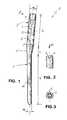
- Fig. 1 illustrates a lateral elevation view of the intramedullaycavity nail according to a preferred aspect of the invention;
- Fig. 2 illustrates a detail of the nail of Fig. 1 seen according toarrow II;
- Fig. 3 illustrates a detail of Fig. 2 seen according to arrow III;
- Figure 4 illustrates a lateral elevation view of the intramedullarycavity nail of Fig. 1 inserted in the medullary canal of a femur;
- Figure 5 illustrates a lateral elevation view of a detail of the nail ofFig. 4;
- Fig. 6 illustrates a lateral elevation view of another detail of thenail of Fig. 4;
- Fig. 7 illustrates a lateral elevation view of a part of an instrumentaccording to a preferred aspect of the invention for fixing theintramedullary cavity nail to the bone;
- Fig. 8 illustrates a general lateral elevation view of the intramedullarycavity nail of Fig. 1, coupled to the instrument for insertion in the medullarycanal.
- With reference to the cited figures, an intramedullary cavity nailaccording to a preferred aspect of the invention, indicated globally by the
reference numeral 1, is generally constituted by a solid elongated body inbiocompatible metal, for example titanium or stainless steel of the type AISI316LVM, essentially formed by aproximal portion 2 united to adistal portion 3by means of a substantially truncated-conicalintermediate portion 4. - Both the
portions - The
proximal portion 2, having a length Lp included for example between70mm and 80mm, has a substantially constant and relatively high averagediameter p, for example comprised between 12mm and 16 mm and preferablyequal to about 14mm, such as to be able to be stably anchored in a hole boredin the trochanteric zone of limited length of the bone. In this manner, oneobtains a reduction of blood loss during the operation of tissue incision and asimplification of the surgical intervention with greater chances of success. - Towards the free end of the
proximal portion 2, a threadedseat 5 isformed whose end edge has a diametrical notch 6. - In the
proximal portion 2 there is provided at least one pair of transversethroughholes cephalic screws 9, 10 for stabilising the femoral headand inclined with respect to the axis ap of theproximal portion 2. - The
holes proximalportion 2 by an average angle of about 115° and may be mutually inclined byabout 10° so as to be convergent, in order to prevent the shifting of the headand the exit of the screws therefrom. - Preferably, the
cephalic screws 9, 10 have respectiveproximal endportions holes nail 2, anddistal end portions - If necessary, in the
proximal portion 2 there may be provided a thirdthroughhole 15, inclined by an average angle of for example about 115° withrespect to the axis ap for a medial Kirschner wire substantially coaxial to thefemoral head, with a smaller diameter than the first two screws and notillustrated in the drawings. - The
distal portion 3, having a length Ld included for example between100mm and 120mm, has an average diameter d less than diameter p of theproximal portion, for example included between 8mm and 10mm andpreferably equal to about 9mm, so as to be able to be easily inserted in themedullary canal of the femur without any boring of the same. - In the distal portion 3 a single through
hole 16 is provided, substantiallyperpendicular to the axis ad, for a diaphysis stabilisation andtorsionalblockage pin 17. Thehole 16 is preferably provided at about half of the lengthLd so as to result sufficiently distant from the free tip of the pin and reducerisks of breakage of its end portion. - Preferably, the
diaphysis pin 17 has asmooth portion 18 with asubstantially constant diameter stably engageable in thehole 15, and athreadedproximal end portion 19 engageable in the spongy tissue of the bone. - Thanks to this configuration, the
nail 1 allows for an optimal stabilisationand a stable and quick synthesis of the bone with a hardly invasive techniqueand with limited blood loss. - Both the cephalic screws and the diaphysis pin may be provided withthe same materials as the nail for obvious reasons of biocompatibility.
- According to a further aspect of the invention, there is provided aninstrument for positioning the above described intramedullary cavity nail andfor performing the necessary drilling of the bone.
- Advantageously, such instrument is constituted by a
drilling mask 20which extends in a principal plane and is formed by agrip 21 which isgraspable by the surgeon and from which atransverse appendix 22 having anend hole 23 extends. Aguide sleeve 24 is keyed in thehole 23 havingdiametrical protrusions orend teeth 25 at its lower end which pass through theprincipal plane of development of the mask and which are engageable in thediametrical notch 6 of theseat 5 of thenail 1 in order to guarantee itsalignment during the intervention. - A
pin 26 with amanoeuvre knob 27 may cross the internal cavity of thesleeve 24 and has a threadedend 28 which engages in the threadedseat 5 ofthepin 1 in order to guarantee its connection with themask 20. - In the lower part of the
grip 21 of themask 20 there are provided guideholes for bone drilling bits in correspondence with theholes - In use, the surgeon performs the drilling of the trochanteric zone of thefemur for about 10cm, whereafter the nail is inserted taking care that the notch6 along the edge of its threaded seat is positioned in a lateral plane of thelimb. Thereafter the nail is connected to the
drilling mask 20 taking care thatthe protrusions orteeth 25 of the guide sleeve 24 of the later are engaged inthe notch 6. Finally, thepin 26 is inserted in thesleeve 24 and its threadedend 28 is screwed in the threadedseat 5 of the pin thereby providing its stableconnection. At this point, the drilling of the bone may be initiated incorrespondence with theholes screws - For the insertion and stabilisation of such screws while avoidingaccidentally dropping them, it is possible to utilise a particular T-shaped tool, illustrated clearly in Fig. 7 and globally indicated by the
reference numeral 29.The tool has amanoeuvring stem 30 with ahead 31 having acentral lockingappendix 32 of hexagonal section engageable in the hexagonal fitting of thescrew and an externaltubular portion 33 with a diametricallongitudinal notch 34 for forming two semicylindrical elastic wings which grip the head of thescrew.
Claims (16)
- Intramedullary cavity nail for the treatment of femoral fractures,comprising a solid elongated body having a proximal portion (2) with atleast one hole for accommodating corresponding screws (9,10) forstabilizing the femoral neck, joined to a distal portion (3) with at leastone distal hole (16) for accommodating at least one diaphysis screw (17)for stabilizing the distal part of the femur, wherein said proximalportion (2) has a substantially constant diameter (Φp) adapted to bestably anchored in a relatively limited length bore of the femur forreducing blood losses, while said distal portion (3) has a substantiallyconstant diameter (Φd) which is less than that of said proximal portionfor being easily inserted in the medullary canal of the femur withoutany drilling,characterized in that said proximal portion (2) has a pairof holes (7, 8) adapted for accommodating respective cephalic screws(9, 10) for the fixing of the femoral head, said holes being inclined withrespect to the axis (ap) of the proximal portion (2) and being alsomutually inclined by about 10° so as to be convergent, in order toprevent the shifting of the femoral head and the exit of the screwstherefrom.
- Intramedullary cavity nail according to claim 1,characterized inthat said holes (7, 8) in the proximal portion (2) are inclined withrespect to the axis (ap) of the proximal portion by an average angle ofabout 115°.
- Intramedullary cavity nail according to claim 1,characterized inthat said cephalic screws (9, 10) have a notably smaller diameter thanthat of said proximal portion (2) and are slightly convergent with respectto one another and with respect to the median axis of the femoral headin order to exert on the latter a reaction force with a longitudinalcomponent for contrasting its shifting and/or the axial penetration.
- Intramedullary cavity nail according to claim 1,characterized inthat said proximal and distal portions (2; 3) are substantially rectilinearand form between themselves a predetermined deviation angle (β) in alateral plane.
- Intramedullary cavity nail according to claim 4,characterized inthat said angle of deviation (β) is comprised between 3° and 10° and ispreferably equal to about 5°.
- Intramedullary cavity nail according to claim 1,characterized inthat the diameter (Φp) of said proximal portion (2) is comprised between12 mm and 16mm and is preferably equal to about 14 mm.
- Intramedullary cavity nail according to claim 1,characterized inthat the diameter (Φd) of said distal portion (3) is comprised between 7mm 25 and 11 mm and is preferably equal to about 9 mm.
- Intramedullary cavity nail according to claim 2,characterized inthat said cephalic screws (9, 10) have respective maximum diameterportions (11, 12) for the accommodation in corresponding holes (7, 8) ofsaid proximal portion (2), with a maximum diameter comprised between3 mm and 8 mm and preferably approximately 7mm.
- Intramedullary cavity nail according to claim 1,characterized inof providing a single diaphysis screw (17) for contrasting torsionalstresses of the nail, accommodated in a single hole (16) substantiallyperpendicular to the axis (ad) of the distal portion (3) provided towardsthe end of the latter farther from said proximal portion (2).
- Intramedullary cavity nail according to claim 9,characterized inthat said diaphysis screw (17) has a substantially constant diameterprincipal portion (18) corresponding to that of said single hole (16) ofsaid 20 distal portion, and an increased diameter threaded portion (19).
- Intramedullary cavity nail according to claim 10,characterizedin that said diaphysis screw (17) is positioned approximately at halflength (Ld) of said distal portion for avoiding breakage of the nailtowards its free end.
- Intramedullary cavity nail according to claim 1,characterized inthat said proximal portion (2) has, in correspondence with its free end, athreaded seat (5) for a connection pin (26) for connection to a drillingmask (20) arranged in the principal plane of the nail.
- Intramedullary cavity nail according to claim 12,characterizedin that the edge of said threaded seat (5) has a diametrical notch (6) coplanar with the principal plane of the nail for the insertion ofalignment protrusions (25) between nail and mask (20).
- Intramedullary cavity nail according to claim 12, characterizedinthat said drilling mask (20) has a grip (21) with a transversalappendix (22) having at its free end an axial hole (23) for the passage ofsaid connection pin (26).
- Intramedullary cavity nail according to claim 14,characterizedin that said grip (21) has a series of guide holes for drilling bits,alignable with the holes (7, 8, 15) of the cephalic and diaphysis screwsin the drilling phase of the bone.
- Intramedullary cavity nail according to claim 1,characterized inthat said screws (9, 10, 17) have such heads to be engaged by a specialtool (29), provided with a longitudinal stem (30) and a head (31) havinga central locking appendix (32) and lateral gripping means (33) forengaging said screws heads ,for avoiding accidentally dropping them.
Applications Claiming Priority (2)
| Application Number | Priority Date | Filing Date | Title |
|---|---|---|---|
| IT97VR000003AIT1293934B1 (en) | 1997-01-21 | 1997-01-21 | ENDOMIDOLLAR NAIL FOR THE TREATMENT OF HIP FRACTURES |
| ITVR970003 | 1997-01-21 |
Publications (2)
| Publication Number | Publication Date |
|---|---|
| EP0853923A1 EP0853923A1 (en) | 1998-07-22 |
| EP0853923B1true EP0853923B1 (en) | 2003-03-26 |
Family
ID=11428280
Family Applications (1)
| Application Number | Title | Priority Date | Filing Date |
|---|---|---|---|
| EP97122921AExpired - LifetimeEP0853923B1 (en) | 1997-01-21 | 1997-12-28 | Intramedullary cavity nail for the treatment of fractures of the hip |
Country Status (13)
| Country | Link |
|---|---|
| US (1) | US6126661A (en) |
| EP (1) | EP0853923B1 (en) |
| JP (1) | JP3630214B2 (en) |
| CN (1) | CN1134244C (en) |
| AR (1) | AR009158A1 (en) |
| AT (1) | ATE235191T1 (en) |
| CA (1) | CA2227290A1 (en) |
| DE (1) | DE69720177T2 (en) |
| ES (1) | ES2195077T3 (en) |
| IT (1) | IT1293934B1 (en) |
| PT (1) | PT853923E (en) |
| TR (1) | TR199800083A2 (en) |
| ZA (1) | ZA9711353B (en) |
Cited By (7)
| Publication number | Priority date | Publication date | Assignee | Title |
|---|---|---|---|---|
| EP1639953A1 (en) | 2004-09-27 | 2006-03-29 | Orthofix International B.V. | Intramedullary nail for the treatment of proximal femur fractures |
| US7527627B2 (en) | 2003-09-08 | 2009-05-05 | Smith & Nephew, Inc. | Orthopaedic implant and screw assembly |
| US7780667B2 (en) | 2003-09-08 | 2010-08-24 | Smith & Nephew, Inc. | Orthopaedic plate and screw assembly |
| US7799030B2 (en) | 2003-09-08 | 2010-09-21 | Smith & Nephew, Inc. | Orthopaedic plate and screw assembly |
| US7918853B2 (en) | 2007-03-20 | 2011-04-05 | Smith & Nephew, Inc. | Orthopaedic plate and screw assembly |
| US8449544B2 (en) | 2009-06-30 | 2013-05-28 | Smith & Nephew, Inc. | Orthopaedic implant and fastener assembly |
| US8834469B2 (en) | 2009-06-30 | 2014-09-16 | Smith & Nephew, Inc. | Orthopaedic implant and fastener assembly |
Families Citing this family (176)
| Publication number | Priority date | Publication date | Assignee | Title |
|---|---|---|---|---|
| US6632224B2 (en)* | 1996-11-12 | 2003-10-14 | Triage Medical, Inc. | Bone fixation system |
| US6648890B2 (en) | 1996-11-12 | 2003-11-18 | Triage Medical, Inc. | Bone fixation system with radially extendable anchor |
| US20050143734A1 (en)* | 1996-11-12 | 2005-06-30 | Cachia Victor V. | Bone fixation system with radially extendable anchor |
| DE29804268U1 (en) | 1998-03-11 | 1998-05-14 | Synthes AG Chur, Chur, Graubünden | Spiral blade insertion instrument |
| US6228445B1 (en)* | 1999-04-06 | 2001-05-08 | Crucible Materials Corp. | Austenitic stainless steel article having a passivated surface layer |
| US6235031B1 (en)* | 2000-02-04 | 2001-05-22 | Encore Medical Corporation | Intramedullary fracture fixation device |
| US6527775B1 (en) | 2000-09-22 | 2003-03-04 | Piper Medical, Inc. | Intramedullary interlocking fixation device for the distal radius |
| US6887243B2 (en) | 2001-03-30 | 2005-05-03 | Triage Medical, Inc. | Method and apparatus for bone fixation with secondary compression |
| US6511481B2 (en) | 2001-03-30 | 2003-01-28 | Triage Medical, Inc. | Method and apparatus for fixation of proximal femoral fractures |
| US6620195B2 (en)* | 2001-04-18 | 2003-09-16 | Medicinelodge, Inc. | Apparatus and method for attaching a graft ligament to a bone |
| US6443954B1 (en) | 2001-04-24 | 2002-09-03 | Dale G. Bramlet | Femoral nail intramedullary system |
| US6648889B2 (en) | 2001-04-24 | 2003-11-18 | Dale G. Bramlet | Intramedullary hip nail with bifurcated lock |
| US6488684B2 (en) | 2001-04-25 | 2002-12-03 | Dale G. Bramlet | Intramedullary nail |
| US6641542B2 (en) | 2001-04-30 | 2003-11-04 | Medtronic, Inc. | Method and apparatus to detect and treat sleep respiratory events |
| EP1260188B1 (en) | 2001-05-25 | 2014-09-17 | Zimmer GmbH | Femoral bone nail for implantation in the knee |
| US20030069581A1 (en)* | 2001-10-04 | 2003-04-10 | Stinson David T. | Universal intramedullary nails, systems and methods of use thereof |
| US6835197B2 (en) | 2001-10-17 | 2004-12-28 | Christoph Andreas Roth | Bone fixation system |
| US7175633B2 (en)* | 2001-10-17 | 2007-02-13 | Synthes (Usa) | Orthopedic implant insertion instruments |
| US6685706B2 (en) | 2001-11-19 | 2004-02-03 | Triage Medical, Inc. | Proximal anchors for bone fixation system |
| US7575578B2 (en)* | 2002-02-13 | 2009-08-18 | Karl Storz Gmbh & Co. Kg | Surgical drill guide |
| DE20204126U1 (en)* | 2002-03-15 | 2003-07-24 | stryker Trauma GmbH, 24232 Schönkirchen | Aiming device for locking nails |
| DE20204655U1 (en) | 2002-03-21 | 2002-06-13 | stryker Trauma GmbH, 24232 Schönkirchen | Locking nail and target device |
| US6793678B2 (en) | 2002-06-27 | 2004-09-21 | Depuy Acromed, Inc. | Prosthetic intervertebral motion disc having dampening |
| JP4988203B2 (en) | 2002-07-19 | 2012-08-01 | インターヴェンショナル スパイン、インコーポレイテッド | Spinal fixation method and spinal fixation device |
| US7001386B2 (en)* | 2002-07-23 | 2006-02-21 | Advanced Orthopaedic Solutions, Inc. | Intramedullary nail for long bone fractures |
| DE20211806U1 (en)* | 2002-08-01 | 2002-10-17 | stryker Trauma GmbH, 24232 Schönkirchen | Aiming device for a locking nail |
| DE20213166U1 (en)* | 2002-08-28 | 2004-01-08 | Stryker Trauma Gmbh | humeral |
| CA2500845C (en)* | 2002-10-03 | 2012-07-31 | Virginia Tech Intellectual Properties, Inc. | Magnetic targeting device |
| US20100249782A1 (en)* | 2002-10-03 | 2010-09-30 | Durham Alfred A | Intramedullary nail targeting device |
| DE20216857U1 (en) | 2002-11-02 | 2003-02-20 | stryker Trauma GmbH, 24232 Schönkirchen | Aiming device for a locking nail |
| US7070601B2 (en) | 2003-01-16 | 2006-07-04 | Triage Medical, Inc. | Locking plate for bone anchors |
| EP1601297B1 (en) | 2003-03-07 | 2013-07-17 | Synthes GmbH | Locking screw for an intramedullary nail |
| ATE477757T1 (en)* | 2003-03-21 | 2010-09-15 | Synthes Gmbh | INTRAMEDULLARY NAIL |
| US7094236B2 (en) | 2003-03-25 | 2006-08-22 | Marc Waisman | Hybrid interlocking proximal femoral fracture fixation |
| WO2004098453A2 (en) | 2003-05-06 | 2004-11-18 | Triage Medical, Inc. | Proximal anchors for bone fixation system |
| WO2004110291A1 (en) | 2003-06-12 | 2004-12-23 | Synthes Ag Chur | Surgical nail |
| ES2348003T3 (en) | 2003-06-12 | 2010-11-26 | Synthes Gmbh | SURGICAL KEY. |
| DE20309399U1 (en)* | 2003-06-18 | 2003-08-28 | stryker Trauma GmbH, 24232 Schönkirchen | Bone nail, especially proximal femoral nail |
| ES2319179T3 (en) | 2003-07-30 | 2009-05-05 | Synthes Gmbh | SURGICAL KEY. |
| US20050027295A1 (en)* | 2003-08-01 | 2005-02-03 | Yang Lin Min | Interlocking nail |
| NZ545342A (en) | 2003-08-29 | 2008-11-28 | Synthes Gmbh | Intramedullary nail |
| ES2340479T3 (en)* | 2003-10-21 | 2010-06-04 | Synthes Gmbh | INTRAMEDULAR KEY. |
| ATE426366T1 (en) | 2004-06-22 | 2009-04-15 | Synthes Gmbh | INTRAMEDULLAR INTRAMEDULLAR NAIL |
| WO2006000109A1 (en)* | 2004-06-24 | 2006-01-05 | Synthes Gmbh | Intramedullary nail |
| CA2571508C (en) | 2004-06-30 | 2012-03-13 | Synthes (U.S.A.) | Surgical nail |
| US20060036248A1 (en)* | 2004-07-01 | 2006-02-16 | Ferrante Joseph M | Fixation elements |
| US7955357B2 (en) | 2004-07-02 | 2011-06-07 | Ellipse Technologies, Inc. | Expandable rod system to treat scoliosis and method of using the same |
| US7588577B2 (en) | 2004-07-15 | 2009-09-15 | Wright Medical Technology, Inc. | Guide assembly for intramedullary fixation and method of using the same |
| US20060015101A1 (en) | 2004-07-15 | 2006-01-19 | Wright Medical Technology, Inc. | Intramedullary fixation assembly and devices and methods for installing the same |
| US20070276404A1 (en)* | 2004-09-16 | 2007-11-29 | Alfa Plastics S.R.L. | Aligning Device for Correctly Inserting Screws Into Holes of Endomedullary Prostheses, and Relative Alignment Method |
| US7481815B2 (en) | 2004-09-23 | 2009-01-27 | Synthes (U.S.A.) | Coplanar X-ray guided aiming arm for locking of intramedullary nails |
| AU2004323972A1 (en)* | 2004-10-14 | 2006-04-20 | Synthes Gmbh | Intramedullary pin for insertion into the medullary space of a femur |
| CA2598679C (en)* | 2005-02-22 | 2014-09-16 | Smith & Nephew, Inc. | Instrument for targeting blocking screws |
| JP2008532707A (en)* | 2005-03-17 | 2008-08-21 | スミス アンド ネフュー インコーポレーテッド | Medical fixing member placement system |
| US7575575B2 (en) | 2005-03-18 | 2009-08-18 | Ron Anthon Olsen | Adjustable splint for osteosynthesis with modular components |
| US7582093B2 (en)* | 2005-04-26 | 2009-09-01 | Amei Technologies, Inc. | Screw extraction and insertion device |
| US20060264951A1 (en) | 2005-05-18 | 2006-11-23 | Nelson Charles L | Minimally Invasive Actuable Bone Fixation Devices Having a Retractable Interdigitation Process |
| US9060820B2 (en) | 2005-05-18 | 2015-06-23 | Sonoma Orthopedic Products, Inc. | Segmented intramedullary fracture fixation devices and methods |
| US8961516B2 (en) | 2005-05-18 | 2015-02-24 | Sonoma Orthopedic Products, Inc. | Straight intramedullary fracture fixation devices and methods |
| US20080249580A1 (en)* | 2005-09-28 | 2008-10-09 | Smith & Nephew, Inc. | Methods and Instruments of Reducing a Fracture |
| ES2251888B1 (en)* | 2005-11-08 | 2007-04-01 | Carlos Enrique Morales Berenguer | DELTA DEVICE FOR THE TREATMENT OF TROCANTERIC AND SUBTOCANTERIC FRACTURES OF FEMUR. |
| US7731738B2 (en) | 2005-12-09 | 2010-06-08 | Orthopro, Llc | Cannulated screw |
| PL1859750T3 (en)* | 2006-05-24 | 2010-01-29 | Lopez Oliva Munoz Felipe | Locking nail system for arthrodesis reconstruction in calcaneus fractures |
| US7862502B2 (en) | 2006-10-20 | 2011-01-04 | Ellipse Technologies, Inc. | Method and apparatus for adjusting a gastrointestinal restriction device |
| WO2008064346A2 (en) | 2006-11-22 | 2008-05-29 | Sonoma Orthopedic Products, Inc. | Fracture fixation device, tools and methods |
| US8579985B2 (en) | 2006-12-07 | 2013-11-12 | Ihip Surgical, Llc | Method and apparatus for hip replacement |
| EP2094197B8 (en) | 2006-12-07 | 2016-03-09 | IHip Surgical, LLC | Apparatus for total hip replacement |
| US8974540B2 (en) | 2006-12-07 | 2015-03-10 | Ihip Surgical, Llc | Method and apparatus for attachment in a modular hip replacement or fracture fixation device |
| WO2008070863A2 (en) | 2006-12-07 | 2008-06-12 | Interventional Spine, Inc. | Intervertebral implant |
| DE102007022648B3 (en)* | 2007-05-15 | 2008-09-11 | Aesculap Ag & Co. Kg | Medullary nail with target body |
| US7998176B2 (en) | 2007-06-08 | 2011-08-16 | Interventional Spine, Inc. | Method and apparatus for spinal stabilization |
| KR101503665B1 (en)* | 2007-06-22 | 2015-03-18 | 이픽스 오소페딕스, 인코포레이티드 | Intramedullary rod for pivoting a fastener |
| US8900307B2 (en) | 2007-06-26 | 2014-12-02 | DePuy Synthes Products, LLC | Highly lordosed fusion cage |
| US8157803B1 (en) | 2007-08-21 | 2012-04-17 | Surgical Implant Generation Network | Bone fixation using an intramedullary nail interlocked with a buttress member |
| US8273091B2 (en)* | 2007-10-04 | 2012-09-25 | Ebi, Llc | Alignment device for locking nail |
| US20090112262A1 (en) | 2007-10-30 | 2009-04-30 | Scott Pool | Skeletal manipulation system |
| US20090112209A1 (en)* | 2007-10-31 | 2009-04-30 | Zimmer, Inc. | Implantation system for intramedullary nail and related methods for implanting intramedullary nails |
| US8771283B2 (en) | 2007-12-17 | 2014-07-08 | Wright Medical Technology, Inc. | Guide assembly for intramedullary fixation and method of using the same |
| EP2237748B1 (en) | 2008-01-17 | 2012-09-05 | Synthes GmbH | An expandable intervertebral implant |
| US20100049198A1 (en)* | 2008-02-21 | 2010-02-25 | Tyco Healthcare Group Lp | Tibial guide for acl repair having off-axis guide wire arrangement |
| US11202707B2 (en) | 2008-03-25 | 2021-12-21 | Nuvasive Specialized Orthopedics, Inc. | Adjustable implant system |
| US8936641B2 (en) | 2008-04-05 | 2015-01-20 | DePuy Synthes Products, LLC | Expandable intervertebral implant |
| US20090299375A1 (en)* | 2008-06-03 | 2009-12-03 | Zimmer, Inc. | Catheter nail targeting guide |
| JP2011523889A (en) | 2008-06-10 | 2011-08-25 | ソノマ・オーソペディック・プロダクツ・インコーポレーテッド | Device, tool and method for fixing fractures |
| US9289220B2 (en) | 2008-06-24 | 2016-03-22 | Extremity Medical Llc | Intramedullary fixation assembly and method of use |
| US9044282B2 (en)* | 2008-06-24 | 2015-06-02 | Extremity Medical Llc | Intraosseous intramedullary fixation assembly and method of use |
| US8343199B2 (en) | 2008-06-24 | 2013-01-01 | Extremity Medical, Llc | Intramedullary fixation screw, a fixation system, and method of fixation of the subtalar joint |
| US8303589B2 (en) | 2008-06-24 | 2012-11-06 | Extremity Medical Llc | Fixation system, an intramedullary fixation assembly and method of use |
| US8328806B2 (en)* | 2008-06-24 | 2012-12-11 | Extremity Medical, Llc | Fixation system, an intramedullary fixation assembly and method of use |
| US9017329B2 (en)* | 2008-06-24 | 2015-04-28 | Extremity Medical, Llc | Intramedullary fixation assembly and method of use |
| US8313487B2 (en) | 2008-06-24 | 2012-11-20 | Extremity Medical Llc | Fixation system, an intramedullary fixation assembly and method of use |
| JP2012504027A (en) | 2008-09-26 | 2012-02-16 | ソノマ・オーソペディック・プロダクツ・インコーポレーテッド | Bone fixation device, tool and method |
| US8790343B2 (en) | 2008-10-11 | 2014-07-29 | Epix Orthopaedics, Inc. | Intramedullary rod with pivotable and fixed fasteners and method for using same |
| US11241257B2 (en) | 2008-10-13 | 2022-02-08 | Nuvasive Specialized Orthopedics, Inc. | Spinal distraction system |
| US8382756B2 (en) | 2008-11-10 | 2013-02-26 | Ellipse Technologies, Inc. | External adjustment device for distraction device |
| US8197490B2 (en) | 2009-02-23 | 2012-06-12 | Ellipse Technologies, Inc. | Non-invasive adjustable distraction system |
| US9526620B2 (en) | 2009-03-30 | 2016-12-27 | DePuy Synthes Products, Inc. | Zero profile spinal fusion cage |
| US9622792B2 (en) | 2009-04-29 | 2017-04-18 | Nuvasive Specialized Orthopedics, Inc. | Interspinous process device and method |
| WO2011002753A1 (en)* | 2009-07-01 | 2011-01-06 | Synthes Usa, Llc | Intramedullary nail and protruding screw locking mechanism |
| US8932301B2 (en)* | 2009-08-26 | 2015-01-13 | Biomet C.V. | Targeting jig for hip fracture nail system |
| JP5751642B2 (en)* | 2009-09-04 | 2015-07-22 | エリプス テクノロジーズ, インク.Ellipse Technologies, Inc. | Bone growth apparatus and method |
| US9393129B2 (en) | 2009-12-10 | 2016-07-19 | DePuy Synthes Products, Inc. | Bellows-like expandable interbody fusion cage |
| JP5497194B2 (en) | 2009-12-11 | 2014-05-21 | スモール・ボーン・イノベーションズ・インコーポレーテッド | Ankle fusion device, instrument, and method |
| US8979860B2 (en) | 2010-06-24 | 2015-03-17 | DePuy Synthes Products. LLC | Enhanced cage insertion device |
| US9907560B2 (en) | 2010-06-24 | 2018-03-06 | DePuy Synthes Products, Inc. | Flexible vertebral body shavers |
| US8623091B2 (en) | 2010-06-29 | 2014-01-07 | DePuy Synthes Products, LLC | Distractible intervertebral implant |
| US9248043B2 (en) | 2010-06-30 | 2016-02-02 | Ellipse Technologies, Inc. | External adjustment device for distraction device |
| WO2012021378A2 (en) | 2010-08-09 | 2012-02-16 | Ellipse Technologies, Inc. | Maintenance feature in magnetic implant |
| US9402732B2 (en) | 2010-10-11 | 2016-08-02 | DePuy Synthes Products, Inc. | Expandable interspinous process spacer implant |
| WO2012112396A2 (en) | 2011-02-14 | 2012-08-23 | Ellipse Technologies, Inc. | Device and method for treating fractured bones |
| US10743794B2 (en) | 2011-10-04 | 2020-08-18 | Nuvasive Specialized Orthopedics, Inc. | Devices and methods for non-invasive implant length sensing |
| US10016220B2 (en) | 2011-11-01 | 2018-07-10 | Nuvasive Specialized Orthopedics, Inc. | Adjustable magnetic devices and methods of using same |
| JP6247644B2 (en) | 2012-02-08 | 2017-12-13 | エピックス オーソペディックス インコーポレイテッド | Implant insertion device having a continuously adjustable targeting assembly |
| WO2013151501A1 (en)* | 2012-04-04 | 2013-10-10 | Kok Sun Khong | Surgical implant device, method and apparatus for implanting thereof |
| US20130338714A1 (en) | 2012-06-15 | 2013-12-19 | Arvin Chang | Magnetic implants with improved anatomical compatibility |
| CN102727288B (en)* | 2012-07-16 | 2016-12-21 | 徐永清 | A kind of carpal bone four foot fusion device location and drilling aid |
| EP2877127B1 (en) | 2012-07-26 | 2019-08-21 | Synthes GmbH | Expandable implant |
| US20140067069A1 (en) | 2012-08-30 | 2014-03-06 | Interventional Spine, Inc. | Artificial disc |
| ITTO20120771A1 (en)* | 2012-09-05 | 2014-03-06 | Im Ligure S R L Unipersonale | NAIL FOR OSTEOSYNTHESIS |
| US9044281B2 (en) | 2012-10-18 | 2015-06-02 | Ellipse Technologies, Inc. | Intramedullary implants for replacing lost bone |
| EP2911616B1 (en) | 2012-10-29 | 2020-10-07 | NuVasive Specialized Orthopedics, Inc. | Adjustable devices for treating arthritis of the knee |
| US9717601B2 (en) | 2013-02-28 | 2017-08-01 | DePuy Synthes Products, Inc. | Expandable intervertebral implant, system, kit and method |
| US9522070B2 (en) | 2013-03-07 | 2016-12-20 | Interventional Spine, Inc. | Intervertebral implant |
| US9179938B2 (en) | 2013-03-08 | 2015-11-10 | Ellipse Technologies, Inc. | Distraction devices and method of assembling the same |
| US10123828B2 (en) | 2013-03-15 | 2018-11-13 | Epix Orthopaedics, Inc. | Implantable device with pivotable fastener and self-adjusting set screw |
| US9522028B2 (en) | 2013-07-03 | 2016-12-20 | Interventional Spine, Inc. | Method and apparatus for sacroiliac joint fixation |
| US10226242B2 (en) | 2013-07-31 | 2019-03-12 | Nuvasive Specialized Orthopedics, Inc. | Noninvasively adjustable suture anchors |
| US9801734B1 (en) | 2013-08-09 | 2017-10-31 | Nuvasive, Inc. | Lordotic expandable interbody implant |
| US10751094B2 (en) | 2013-10-10 | 2020-08-25 | Nuvasive Specialized Orthopedics, Inc. | Adjustable spinal implant |
| US9770278B2 (en) | 2014-01-17 | 2017-09-26 | Arthrex, Inc. | Dual tip guide wire |
| JP6396484B2 (en)* | 2014-02-12 | 2018-09-26 | スウェマック・イノヴェーション・アーベー | Target setting device and target setting method |
| CN106456215B (en) | 2014-04-28 | 2020-04-10 | 诺威适骨科专科公司 | External adjustment device for adjusting a medical implant |
| DE102014113556A1 (en)* | 2014-09-19 | 2016-03-24 | Königsee Implantate GmbH | Osteosynthesis aids for the treatment of subtrochanteric fractures and / or pertrochanteric fractures and / or femoral neck fractures |
| US9814499B2 (en) | 2014-09-30 | 2017-11-14 | Arthrex, Inc. | Intramedullary fracture fixation devices and methods |
| KR102588501B1 (en) | 2014-10-23 | 2023-10-11 | 누베이시브 스페셜라이즈드 오소페딕스, 인크. | Remotely adjustable interactive bone reshaping implant |
| ES2908064T3 (en) | 2014-12-26 | 2022-04-27 | Nuvasive Specialized Orthopedics Inc | distraction systems |
| US10238427B2 (en) | 2015-02-19 | 2019-03-26 | Nuvasive Specialized Orthopedics, Inc. | Systems and methods for vertebral adjustment |
| US11426290B2 (en) | 2015-03-06 | 2022-08-30 | DePuy Synthes Products, Inc. | Expandable intervertebral implant, system, kit and method |
| TWI589263B (en)* | 2015-06-04 | 2017-07-01 | 愛派司生技股份有限公司 | A fixation system for hip fracture use thereof |
| US9913727B2 (en) | 2015-07-02 | 2018-03-13 | Medos International Sarl | Expandable implant |
| US11213334B2 (en) | 2015-10-07 | 2022-01-04 | Stabiliz Orthopaedics, LLC | Bone fracture fixation device with transverse set screw and aiming guide |
| BR112018007347A2 (en) | 2015-10-16 | 2018-10-23 | Nuvasive Specialized Orthopedics, Inc. | adjustable devices for the treatment of knee arthritis |
| CN108601611B (en) | 2015-12-10 | 2021-11-02 | 诺威适骨科专科公司 | External adjustment device for stretcher |
| AU2016382956A1 (en)* | 2015-12-28 | 2018-08-09 | Glenhurst Labs, Llc | Surgical devices for small bone fracture surgery |
| BR112018015504A2 (en) | 2016-01-28 | 2018-12-18 | Nuvasive Specialized Orthopedics, Inc. | bone transport systems |
| WO2017139548A1 (en) | 2016-02-10 | 2017-08-17 | Nuvasive Specialized Orthopedics, Inc. | Systems and methods for controlling multiple surgical variables |
| KR101722252B1 (en)* | 2016-03-18 | 2017-04-03 | 이동훈 | Intramedullary nail having an anti-tilting fuction |
| US10695110B2 (en)* | 2016-04-25 | 2020-06-30 | Sakae Tanaka | Internal fixator for bone fracture |
| ITUA20163613A1 (en)* | 2016-05-19 | 2017-11-19 | Orthofix Srl | Perfected instruments for aligning fixing screws to be inserted in the cross holes of nails for long bones, in particular marrow nails |
| EP3474784A2 (en) | 2016-06-28 | 2019-05-01 | Eit Emerging Implant Technologies GmbH | Expandable and angularly adjustable intervertebral cages with articulating joint |
| US11510788B2 (en) | 2016-06-28 | 2022-11-29 | Eit Emerging Implant Technologies Gmbh | Expandable, angularly adjustable intervertebral cages |
| US10537436B2 (en) | 2016-11-01 | 2020-01-21 | DePuy Synthes Products, Inc. | Curved expandable cage |
| US10888433B2 (en) | 2016-12-14 | 2021-01-12 | DePuy Synthes Products, Inc. | Intervertebral implant inserter and related methods |
| US10874433B2 (en) | 2017-01-30 | 2020-12-29 | Stryker European Holdings I, Llc | Strut attachments for external fixation frame |
| US10398563B2 (en) | 2017-05-08 | 2019-09-03 | Medos International Sarl | Expandable cage |
| US11344424B2 (en) | 2017-06-14 | 2022-05-31 | Medos International Sarl | Expandable intervertebral implant and related methods |
| US10940016B2 (en) | 2017-07-05 | 2021-03-09 | Medos International Sarl | Expandable intervertebral fusion cage |
| US11446072B2 (en) | 2017-10-10 | 2022-09-20 | DePuy Synthes Products, Inc. | Self-retaining nail to insertion handle interface |
| MX2020003481A (en) | 2017-10-11 | 2020-12-07 | Howmedica Osteonics Corp | Humeral fixation plate guides. |
| US10932828B2 (en) | 2018-01-25 | 2021-03-02 | Advanced Orthopaedic Solutions, Inc. | Bone nail |
| US11446156B2 (en) | 2018-10-25 | 2022-09-20 | Medos International Sarl | Expandable intervertebral implant, inserter instrument, and related methods |
| JP2022519380A (en) | 2019-02-07 | 2022-03-23 | ニューベイシブ スペシャライズド オーソペディックス,インコーポレイテッド | Ultrasonic communication in medical devices |
| US11589901B2 (en) | 2019-02-08 | 2023-02-28 | Nuvasive Specialized Orthopedics, Inc. | External adjustment device |
| IT201900005180A1 (en)* | 2019-04-05 | 2020-10-05 | Enrico Paganelli | ENDOMIDOLLAR NAIL |
| CN109984873A (en)* | 2019-05-14 | 2019-07-09 | 赵滨 | It is a kind of for filling up and supporting the ossis implants block of the dry epiphysis defect of long bone of limbs |
| EP4003198B1 (en) | 2019-07-26 | 2025-01-08 | GLW, Inc. | Intramedullary rod with intrabody outrigger interface |
| US11426286B2 (en) | 2020-03-06 | 2022-08-30 | Eit Emerging Implant Technologies Gmbh | Expandable intervertebral implant |
| US12213708B2 (en) | 2020-09-08 | 2025-02-04 | Nuvasive Specialized Orthopedics, Inc. | Remote control module for adjustable implants |
| US20220265326A1 (en) | 2021-02-23 | 2022-08-25 | Nuvasive Specialized Orthopedics, Inc. | Adjustable implant, system and methods |
| US11850160B2 (en) | 2021-03-26 | 2023-12-26 | Medos International Sarl | Expandable lordotic intervertebral fusion cage |
| US11752009B2 (en) | 2021-04-06 | 2023-09-12 | Medos International Sarl | Expandable intervertebral fusion cage |
| US11737787B1 (en) | 2021-05-27 | 2023-08-29 | Nuvasive, Inc. | Bone elongating devices and methods of use |
| EP4380480A1 (en) | 2021-08-03 | 2024-06-12 | NuVasive Specialized Orthopedics, Inc. | Adjustable implant |
| US12090064B2 (en) | 2022-03-01 | 2024-09-17 | Medos International Sarl | Stabilization members for expandable intervertebral implants, and related systems and methods |
| US12004785B2 (en) | 2022-04-21 | 2024-06-11 | DePuy Synthes Products, Inc. | Retrograde femoral intramedullary nail, and related systems and methods |
| CN114795436B (en)* | 2022-04-27 | 2025-05-16 | 航天中心医院 | Internal fixation device |
Family Cites Families (21)
| Publication number | Priority date | Publication date | Assignee | Title |
|---|---|---|---|---|
| US3433220A (en)* | 1966-12-30 | 1969-03-18 | Robert E Zickel | Intramedullary rod and cross-nail assembly for treating femur fractures |
| US4622959A (en)* | 1985-03-05 | 1986-11-18 | Marcus Randall E | Multi-use femoral intramedullary nail |
| US5167663A (en)* | 1986-12-30 | 1992-12-01 | Smith & Nephew Richards Inc. | Femoral fracture device |
| US5312406A (en)* | 1986-12-30 | 1994-05-17 | Smith & Nephew Richards Inc. | Method of treating an intertrochanteric fracture |
| US5176681A (en)* | 1987-12-14 | 1993-01-05 | Howmedica International Inc. | Intramedullary intertrochanteric fracture fixation appliance and fitting device |
| US4875474A (en)* | 1988-01-29 | 1989-10-24 | Biomet, Inc. | Variable wall thickness interlocking intramedullary nail |
| EP0355411A1 (en)* | 1988-08-10 | 1990-02-28 | Ace Medical Company | Intramedullary rod for femur stabilization |
| CH683065A5 (en)* | 1990-03-20 | 1994-01-14 | Synthes Ag | Tibial intramedullary nail with adapted cross-section. |
| DE9109883U1 (en)* | 1991-08-09 | 1991-09-26 | Howmedica GmbH, 2314 Schönkirchen | Locking nail for the treatment of femoral fractures in the middle and trochanteric region |
| DE4318150C2 (en)* | 1993-06-01 | 1996-08-01 | Endocare Ag | Osteosynthesis tools for the treatment of subtrochanteric and pertrochanteric fractures as well as fractures of the femoral neck |
| US5429640A (en)* | 1992-11-27 | 1995-07-04 | Clemson University | Intramedullary rod for fracture fixation of femoral shaft independent of ipsilateral femoral neck fracture fixation |
| WO1994013219A1 (en)* | 1992-12-04 | 1994-06-23 | Frigg, Robert | Modular marrow nail |
| IT1272537B (en)* | 1993-08-30 | 1997-06-23 | Synos Medical Spa | ENDOMIDOLLAR NAIL FOR THE SYNTHESIS OF THE PROXIMAL FEMORE FRACTURES AND EQUIPMENT FOR ITS POSITIONING |
| FR2713914B1 (en)* | 1993-12-21 | 1996-02-09 | Medinov Sa | Central medullary tibial nail and its delivery device. |
| US5472444A (en)* | 1994-05-13 | 1995-12-05 | Acumed, Inc. | Humeral nail for fixation of proximal humeral fractures |
| US5536127A (en)* | 1994-10-13 | 1996-07-16 | Pennig; Dietmar | Headed screw construction for use in fixing the position of an intramedullary nail |
| JP3345235B2 (en)* | 1995-01-30 | 2002-11-18 | 旭光学工業株式会社 | Intramedullary nail for humerus |
| US5766174A (en)* | 1995-09-26 | 1998-06-16 | Orthologic Corporation | Intramedullary bone fixation device |
| US5941885A (en)* | 1996-10-08 | 1999-08-24 | Jackson; Roger P. | Tools for use in installing osteosynthesis apparatus utilizing set screw with break-off head |
| US5766179A (en)* | 1997-03-05 | 1998-06-16 | Orthofix S.R.L. | Mechanical system for blind nail-hole alignment of bone screws |
| US5800440A (en)* | 1997-03-18 | 1998-09-01 | Johnson & Johnson Professional, Inc. | Device for inserting a surgical pin |
- 1997
- 1997-01-21ITIT97VR000003Apatent/IT1293934B1/enactiveIP Right Grant
- 1997-12-18ZAZA9711353Apatent/ZA9711353B/enunknown
- 1997-12-26JPJP35873897Apatent/JP3630214B2/ennot_activeExpired - Fee Related
- 1997-12-28EPEP97122921Apatent/EP0853923B1/ennot_activeExpired - Lifetime
- 1997-12-28ATAT97122921Tpatent/ATE235191T1/enactive
- 1997-12-28PTPT97122921Tpatent/PT853923E/enunknown
- 1997-12-28DEDE69720177Tpatent/DE69720177T2/ennot_activeExpired - Lifetime
- 1997-12-28ESES97122921Tpatent/ES2195077T3/ennot_activeExpired - Lifetime
- 1998
- 1998-01-20CACA002227290Apatent/CA2227290A1/ennot_activeAbandoned
- 1998-01-20TRTR1998/00083Apatent/TR199800083A2/enunknown
- 1998-01-20USUS09/008,943patent/US6126661A/ennot_activeExpired - Lifetime
- 1998-01-20CNCNB98105630XApatent/CN1134244C/ennot_activeExpired - Fee Related
- 1998-01-21ARARP980100265Apatent/AR009158A1/ennot_activeApplication Discontinuation
Cited By (14)
| Publication number | Priority date | Publication date | Assignee | Title |
|---|---|---|---|---|
| US8187275B2 (en) | 2003-09-08 | 2012-05-29 | Smith & Nephew, Inc. | Orthopaedic implant and fastening assembly |
| US8617161B2 (en) | 2003-09-08 | 2013-12-31 | Smith & Nephew, Inc. | Orthopaedic plate and fastener assembly |
| US7534244B2 (en) | 2003-09-08 | 2009-05-19 | Smith & Nephew, Inc. | Orthopaedic plate and screw assembly |
| US7780667B2 (en) | 2003-09-08 | 2010-08-24 | Smith & Nephew, Inc. | Orthopaedic plate and screw assembly |
| US7799030B2 (en) | 2003-09-08 | 2010-09-21 | Smith & Nephew, Inc. | Orthopaedic plate and screw assembly |
| US7883509B2 (en) | 2003-09-08 | 2011-02-08 | Smith & Nephew, Inc. | Orthopaedic implant and screw assembly |
| US8105326B2 (en) | 2003-09-08 | 2012-01-31 | Smith & Nephew, Inc. | Orthopaedic implant and fastener assembly |
| US7931652B2 (en) | 2003-09-08 | 2011-04-26 | Smith & Nephew, Inc. | Orthopaedic plate and screw assembly |
| US7527627B2 (en) | 2003-09-08 | 2009-05-05 | Smith & Nephew, Inc. | Orthopaedic implant and screw assembly |
| US8298234B2 (en) | 2003-09-08 | 2012-10-30 | Smith & Nephew, Inc. | Orthopaedic implant and fastener assembly |
| EP1639953A1 (en) | 2004-09-27 | 2006-03-29 | Orthofix International B.V. | Intramedullary nail for the treatment of proximal femur fractures |
| US7918853B2 (en) | 2007-03-20 | 2011-04-05 | Smith & Nephew, Inc. | Orthopaedic plate and screw assembly |
| US8449544B2 (en) | 2009-06-30 | 2013-05-28 | Smith & Nephew, Inc. | Orthopaedic implant and fastener assembly |
| US8834469B2 (en) | 2009-06-30 | 2014-09-16 | Smith & Nephew, Inc. | Orthopaedic implant and fastener assembly |
Also Published As
| Publication number | Publication date |
|---|---|
| ITVR970003A1 (en) | 1998-07-21 |
| ES2195077T3 (en) | 2003-12-01 |
| ATE235191T1 (en) | 2003-04-15 |
| US6126661A (en) | 2000-10-03 |
| JP3630214B2 (en) | 2005-03-16 |
| CN1134244C (en) | 2004-01-14 |
| DE69720177T2 (en) | 2004-02-12 |
| CA2227290A1 (en) | 1998-07-21 |
| IT1293934B1 (en) | 1999-03-11 |
| JPH10211214A (en) | 1998-08-11 |
| PT853923E (en) | 2003-07-31 |
| DE69720177D1 (en) | 2003-04-30 |
| TR199800083A2 (en) | 1998-08-21 |
| EP0853923A1 (en) | 1998-07-22 |
| ZA9711353B (en) | 1998-06-23 |
| CN1198317A (en) | 1998-11-11 |
| AR009158A1 (en) | 2000-03-08 |
Similar Documents
| Publication | Publication Date | Title |
|---|---|---|
| EP0853923B1 (en) | Intramedullary cavity nail for the treatment of fractures of the hip | |
| JP4932715B2 (en) | Intramedullary rod with spiral flutes | |
| EP0192840B1 (en) | Appliance for fixing fractures of the femur | |
| EP2782511B1 (en) | Implant system for bone fixation | |
| US8128627B2 (en) | Segmented intramedullary system and apparatus | |
| US6123708A (en) | Intramedullary bone fixation rod | |
| EP3448291B1 (en) | Intramedullary nail system | |
| GB2209947A (en) | Device for fixing femur fractures | |
| EP3636175A2 (en) | Systems for intramedullary nail implantation | |
| EP4252682B1 (en) | A femoral nail and instrumentation system | |
| JP2023105819A (en) | Systems and methods for intramedullary nail implantation | |
| CN218391247U (en) | Femoral intertrochanteric fracture restorer | |
| MXPA98000013A (en) | Nail of intramedular cavity for the treatment of fractures of the cad | |
| KR101200899B1 (en) | Intramedullary rod with spiraling flutes |
Legal Events
| Date | Code | Title | Description |
|---|---|---|---|
| PUAI | Public reference made under article 153(3) epc to a published international application that has entered the european phase | Free format text:ORIGINAL CODE: 0009012 | |
| AK | Designated contracting states | Kind code of ref document:A1 Designated state(s):AT CH DE ES FR GB GR IT LI PT | |
| AX | Request for extension of the european patent | Free format text:AL;LT;LV;MK;RO;SI | |
| 17P | Request for examination filed | Effective date:19981204 | |
| AKX | Designation fees paid | Free format text:AT CH DE ES FR GB GR IT LI PT | |
| RBV | Designated contracting states (corrected) | Designated state(s):AT CH DE ES FR GB GR IT LI PT | |
| 17Q | First examination report despatched | Effective date:20010322 | |
| GRAH | Despatch of communication of intention to grant a patent | Free format text:ORIGINAL CODE: EPIDOS IGRA | |
| GRAH | Despatch of communication of intention to grant a patent | Free format text:ORIGINAL CODE: EPIDOS IGRA | |
| GRAA | (expected) grant | Free format text:ORIGINAL CODE: 0009210 | |
| AK | Designated contracting states | Designated state(s):AT CH DE ES FR GB GR IT LI PT | |
| PG25 | Lapsed in a contracting state [announced via postgrant information from national office to epo] | Ref country code:LI Free format text:LAPSE BECAUSE OF FAILURE TO SUBMIT A TRANSLATION OF THE DESCRIPTION OR TO PAY THE FEE WITHIN THE PRESCRIBED TIME-LIMIT Effective date:20030326 Ref country code:CH Free format text:LAPSE BECAUSE OF FAILURE TO SUBMIT A TRANSLATION OF THE DESCRIPTION OR TO PAY THE FEE WITHIN THE PRESCRIBED TIME-LIMIT Effective date:20030326 | |
| REG | Reference to a national code | Ref country code:GB Ref legal event code:FG4D | |
| REG | Reference to a national code | Ref country code:CH Ref legal event code:EP | |
| REF | Corresponds to: | Ref document number:69720177 Country of ref document:DE Date of ref document:20030430 Kind code of ref document:P | |
| REG | Reference to a national code | Ref country code:GR Ref legal event code:EP Ref document number:20030402323 Country of ref document:GR | |
| REG | Reference to a national code | Ref country code:CH Ref legal event code:PL | |
| ET | Fr: translation filed | ||
| PLBE | No opposition filed within time limit | Free format text:ORIGINAL CODE: 0009261 | |
| STAA | Information on the status of an ep patent application or granted ep patent | Free format text:STATUS: NO OPPOSITION FILED WITHIN TIME LIMIT | |
| 26N | No opposition filed | Effective date:20031230 | |
| REG | Reference to a national code | Ref country code:GB Ref legal event code:732E | |
| REG | Reference to a national code | Ref country code:FR Ref legal event code:TP | |
| REG | Reference to a national code | Ref country code:GB Ref legal event code:732E | |
| REG | Reference to a national code | Ref country code:PT Ref legal event code:PC4A Owner name:ORTHOFIX S.R.L., IT Effective date:20080314 | |
| PGFP | Annual fee paid to national office [announced via postgrant information from national office to epo] | Ref country code:AT Payment date:20101125 Year of fee payment:14 | |
| PGFP | Annual fee paid to national office [announced via postgrant information from national office to epo] | Ref country code:GB Payment date:20101201 Year of fee payment:14 Ref country code:GR Payment date:20101125 Year of fee payment:14 | |
| PGFP | Annual fee paid to national office [announced via postgrant information from national office to epo] | Ref country code:PT Payment date:20111205 Year of fee payment:15 | |
| PGFP | Annual fee paid to national office [announced via postgrant information from national office to epo] | Ref country code:DE Payment date:20121122 Year of fee payment:16 | |
| PGFP | Annual fee paid to national office [announced via postgrant information from national office to epo] | Ref country code:ES Payment date:20121205 Year of fee payment:16 Ref country code:IT Payment date:20121126 Year of fee payment:16 | |
| PGFP | Annual fee paid to national office [announced via postgrant information from national office to epo] | Ref country code:FR Payment date:20130130 Year of fee payment:16 | |
| REG | Reference to a national code | Ref country code:PT Ref legal event code:MM4A Free format text:LAPSE DUE TO NON-PAYMENT OF FEES Effective date:20130628 | |
| REG | Reference to a national code | Ref country code:AT Ref legal event code:MM01 Ref document number:235191 Country of ref document:AT Kind code of ref document:T Effective date:20121228 | |
| GBPC | Gb: european patent ceased through non-payment of renewal fee | Effective date:20121228 | |
| PG25 | Lapsed in a contracting state [announced via postgrant information from national office to epo] | Ref country code:PT Free format text:LAPSE BECAUSE OF NON-PAYMENT OF DUE FEES Effective date:20130628 | |
| REG | Reference to a national code | Ref country code:GR Ref legal event code:ML Ref document number:20030402323 Country of ref document:GR Effective date:20130703 | |
| PG25 | Lapsed in a contracting state [announced via postgrant information from national office to epo] | Ref country code:AT Free format text:LAPSE BECAUSE OF NON-PAYMENT OF DUE FEES Effective date:20121228 Ref country code:GR Free format text:LAPSE BECAUSE OF NON-PAYMENT OF DUE FEES Effective date:20130703 | |
| PG25 | Lapsed in a contracting state [announced via postgrant information from national office to epo] | Ref country code:GB Free format text:LAPSE BECAUSE OF NON-PAYMENT OF DUE FEES Effective date:20121228 | |
| REG | Reference to a national code | Ref country code:DE Ref legal event code:R119 Ref document number:69720177 Country of ref document:DE | |
| REG | Reference to a national code | Ref country code:FR Ref legal event code:ST Effective date:20140829 | |
| REG | Reference to a national code | Ref country code:DE Ref legal event code:R119 Ref document number:69720177 Country of ref document:DE Effective date:20140701 | |
| PG25 | Lapsed in a contracting state [announced via postgrant information from national office to epo] | Ref country code:DE Free format text:LAPSE BECAUSE OF NON-PAYMENT OF DUE FEES Effective date:20140701 | |
| PG25 | Lapsed in a contracting state [announced via postgrant information from national office to epo] | Ref country code:FR Free format text:LAPSE BECAUSE OF NON-PAYMENT OF DUE FEES Effective date:20131231 | |
| REG | Reference to a national code | Ref country code:ES Ref legal event code:FD2A Effective date:20150406 | |
| PG25 | Lapsed in a contracting state [announced via postgrant information from national office to epo] | Ref country code:ES Free format text:LAPSE BECAUSE OF NON-PAYMENT OF DUE FEES Effective date:20131229 | |
| PG25 | Lapsed in a contracting state [announced via postgrant information from national office to epo] | Ref country code:IT Free format text:LAPSE BECAUSE OF NON-PAYMENT OF DUE FEES Effective date:20131231 | |
| PG25 | Lapsed in a contracting state [announced via postgrant information from national office to epo] | Ref country code:IT Free format text:LAPSE BECAUSE OF NON-PAYMENT OF DUE FEES Effective date:20131228 |