EP0853908B1 - Valve arrangement - Google Patents
Valve arrangementDownload PDFInfo
- Publication number
- EP0853908B1 EP0853908B1EP19980300184EP98300184AEP0853908B1EP 0853908 B1EP0853908 B1EP 0853908B1EP 19980300184EP19980300184EP 19980300184EP 98300184 AEP98300184 AEP 98300184AEP 0853908 B1EP0853908 B1EP 0853908B1
- Authority
- EP
- European Patent Office
- Prior art keywords
- aperture
- trigger member
- carriage member
- coffee
- valve
- Prior art date
- Legal status (The legal status is an assumption and is not a legal conclusion. Google has not performed a legal analysis and makes no representation as to the accuracy of the status listed.)
- Expired - Lifetime
Links
- 239000012530fluidSubstances0.000claimsdescription11
- 238000007789sealingMethods0.000claimsdescription2
- 230000037452primingEffects0.000claims1
- 238000010276constructionMethods0.000description3
- 230000003993interactionEffects0.000description3
- 239000007788liquidSubstances0.000description3
- 230000000694effectsEffects0.000description2
- 238000004519manufacturing processMethods0.000description2
- 235000013361beverageNutrition0.000description1
- 230000002939deleterious effectEffects0.000description1
- 238000010186stainingMethods0.000description1
- 238000010025steamingMethods0.000description1
Images

Classifications
- A—HUMAN NECESSITIES
- A47—FURNITURE; DOMESTIC ARTICLES OR APPLIANCES; COFFEE MILLS; SPICE MILLS; SUCTION CLEANERS IN GENERAL
- A47J—KITCHEN EQUIPMENT; COFFEE MILLS; SPICE MILLS; APPARATUS FOR MAKING BEVERAGES
- A47J31/00—Apparatus for making beverages
- A47J31/06—Filters or strainers for coffee or tea makers ; Holders therefor
- A47J31/0605—Filters or strainers for coffee or tea makers ; Holders therefor with a valve at the filter-outlet; Anti-drip devices
- A47J31/061—Filters or strainers for coffee or tea makers ; Holders therefor with a valve at the filter-outlet; Anti-drip devices activated by the beverage container
Definitions
- This inventionrelates to valve arrangements and it relates especially, though not exclusively, to such arrangements as may be used, for example, in domestic beverage-making appliances to ensure that the beverage is not released unless the intended receptacle is properly placed to receive it.
- Such arrangementsare commonly used in domestic coffee-making appliances in which a carafe, intended to hold the brewed coffee, is positioned beneath an outlet from the coffee-brewing station anal stands upon a heated base which is intended to keep the coffee warm until it is used.
- the outlethas associated with it a valve arrangement which is biased to the closed position, being urged open only in response to interaction between a component of the valve arrangement and the lid, or the rim, of the carafe.
- valve arrangementsinclude, as the closure member for the outlet, a conically-shaped resilient valve head which is urged into or withdrawn from the outlet, depending on the presence or absence of the carafe as outlined above.
- a conically-shaped resilient valve headwhich is urged into or withdrawn from the outlet, depending on the presence or absence of the carafe as outlined above.
- the coffeecan run down on to the heated base on which the carafe stands, and cause unwanted spattering and steaming or even invade the area, beneath the base, where various electrical connections exist.
- the depositscan, indeed, build up to such an extent that the valve cannot seal properly, and this can allow coffee to drip from the brewing station even when there is no carafe in place to receive it, so that direct dripping of coffee on to the heated base can occur.
- EP-A-11 1969describes a valving arrangement for appliances such as coffee makers according to the preamble of claim 1, in which a valve head is carried at the end of a cranked arm that can be tilted, in response to vertical movement of a knob that is pushed upwards by contact with a coffee pot, to open or close a valve aperture through which coffee exits to the pot.
- the degree to which the valve opens, and thus the exit flow rate of the coffeeis controllable by means of a manually adjustable slider which mechanically limits the travel of the arm bearing the valve head.
- This constructionrequires the cranked arm to be pivotally mounted in the close vicinity of the aperture through which the coffee exits, however, and the relatively small pivoting movements made might be interfered with, over time, by coffee products and debris.
- the present inventionseeks to avoid such problems by imparting a robust and positively acting opening and closure motion to the valve head.
- a valve arrangement for controlling the flow of a fluidcomprising a reservoir for the fluid, an aperture (2) formed in an inclined portion of a base-wall (1) of the reservoir, a valve head (3) for selectively sealing the aperture (2) against flow of the fluid therethrough, a carriage member (4) bearing the valve head and capable of movement relative to the aperture, and a trigger member (8) capable of movement relative to the carriage member, said relative movement being constrained, by respective path-defining components (6,7) associated with the members (4,8), to operate between a first position, in which the head is urged by the action of resilient means (9) into the aperture, and a second position in which the valve head is withdrawn from the aperture against the action of said resilient means, thereby opening the aperture to fluid flow, the trigger member (8) being disposed, in said first position, to be engageable by part of a receptacle (19) positioned to receive fluid exiting the aperture in a flow direction, the trigger member (8) being urged, by contact with said part of the receptacle, to
- Another feature typical of coffee-makersis that they are provided with a housing which can be hinged open to permit the brewing cavity to be charged with fresh coffee and filters. It is quite important that the aforementioned valve assembly, which is commonly located at the bale of the brewing cavity's housing, remains closed until such time as the housing is properly closed.
- valve assemblythat interacts with the carafe should also be effective to detect the open condition of the housing, and some attempts have been made in the past to achieve this.
- the valving arrangementhas a closure member which does not lie in the direct flow path of fluid when the valve is open.
- Figures 1(a), 1(b) and 1(c)show, in cross-section, various stages of operation of a valving arrangement, in accordance with one example of the invention, used in a coffee-making appliance
- Figure 2shows, in cross-sectional view, the interaction of the valving arrangement of Figure 1 with a carafe intended to receive the coffee.
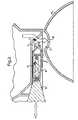
- Figure 1(a)shows the valving arrangement in its closed position.
- a part of the base of the brewing cavityis shown at 1; the valve arrangement generally shown at 1 a being secured to it.
- the base 1is formed with an outlet aperture 2 which is closed by a conical, resilient valve-head 3.
- the head 3is supported by a carriage member 4 of box section, the upper surface of which can slide along the flat undersurface 5 of the base 1.
- the side-walls of the carriage member 4are formed with shaped slots such as 6 which form cam surfaces in which a pin 7, which is part of a trigger member 8, can slide.
- the pin 7runs transversely across the trigger member 8 and protrudes through its side-walls such as 9 into the slots such as 6.
- the shaped slots 6 and the pin 7constitute path-defining elements that constrain the relative motion of the trigger member 8 and the carriage member 4 to follow a predetermined path.
- the rear wall 10 of trigger member 8 and a front wall 11 of the carriage member 4are urged apart by a spring 12.
- FIG. 1(b)this illustrates the situation that obtains when the housing which includes the base 1 is hinged to its properly closed position in relation to the appliance, but no carafe is in place.
- a nose member 14integrally formed with or secured to a fixed part of the appliance, engages with the rear wall 10 of trigger member 8 and causes this member to slide forwards relative to carriage member 4.
- This movementis accommodated by virtue of movement of the pin 7 down the ramp portion 15 of slot 6 and into a flat, intermediate portion 16 thereof, and causes a misalignment of the two members 8 and 4 which is critical to the operation of the valve.
- the valve head 3remains firmly urged into the aperture 2 but the trigger member adopts a primed condition in which it is ready to be actuated by engagement with part of a carafe when the latter is placed beneath the aperture.
- Figure 2shows how the lid 19 of a carafe (not shown) can be used to interact with the trigger member 8 to open the valve.
- the lid 19is formed with a central aperture 20, through which the coffee is intended to enter the carafe.
- the aperturelies in a well 21 which allows for some build-up of brewed coffee so that spillage does not occur in the event that, temporarily, the outflow of coffee from the outlet 2 exceeds the inflow capacity of the aperture 1.
- a valve assembly operative only between the primed position ( Figure 1(b)) and the opened position ( Figure 1(c))may be provided within the scope of the invention for applications in which the part of the operation associated with the nose 14 is not required.
Landscapes
- Engineering & Computer Science (AREA)
- Food Science & Technology (AREA)
- Apparatus For Making Beverages (AREA)
Description
- This invention relates to valve arrangements and it relates especially, though notexclusively, to such arrangements as may be used, for example, in domestic beverage-makingappliances to ensure that the beverage is not released unless the intendedreceptacle is properly placed to receive it.
- Such arrangements are commonly used in domestic coffee-making appliances inwhich a carafe, intended to hold the brewed coffee, is positioned beneath an outlet fromthe coffee-brewing station anal stands upon a heated base which is intended to keep thecoffee warm until it is used. Conventionally, the outlet has associated with it a valvearrangement which is biased to the closed position, being urged open only in response tointeraction between a component of the valve arrangement and the lid, or the rim, of thecarafe.
- Usually such valve arrangements include, as the closure member for the outlet, aconically-shaped resilient valve head which is urged into or withdrawn from the outlet,depending on the presence or absence of the carafe as outlined above. When the valvehead is withdrawn from the outlet, however, it remains in the direct flow path of thecoffee, which effectively spills over it, and in time this causes build-up of deposits on thevalve head with associated reduction in the valving efficiency and in the generalappearance and operation of the appliance as a whole, since the flow of coffee tends to beinterfered with by the valve head and the liquid tends to dribble into areas where it causesstaining.
- In extreme cases, the coffee can run down on to the heated base on which thecarafe stands, and cause unwanted spattering and steaming or even invade the area,beneath the base, where various electrical connections exist. Furthermore, the depositscan, indeed, build up to such an extent that the valve cannot seal properly, and this canallow coffee to drip from the brewing station even when there is no carafe in place toreceive it, so that direct dripping of coffee on to the heated base can occur.
- It is an object of this invention to provide a reliable valving arrangement which isconstructed so as to reduce the risk of deleterious build-up of deposits and/or of the effects of such deposits, by arranging that the valve's closure member is withdrawn fromthe direct path of liquid flowing through the valved outlet when the valve is opened.
- EP-A-11 1969 describes a valving arrangement for appliances such as coffeemakers according to the preamble of
claim 1, in which a valve head is carried at the end of a cranked arm that can be tilted, inresponse to vertical movement of a knob that is pushed upwards by contact with a coffeepot, to open or close a valve aperture through which coffee exits to the pot. The degree towhich the valve opens, and thus the exit flow rate of the coffee is controllable by meansof a manually adjustable slider which mechanically limits the travel of the arm bearingthe valve head. This construction requires the cranked arm to be pivotally mounted in theclose vicinity of the aperture through which the coffee exits, however, and the relativelysmall pivoting movements made might be interfered with, over time, by coffee productsand debris. The present invention seeks to avoid such problems by imparting a robust andpositively acting opening and closure motion to the valve head. - According to the invention there is provided a valve arrangement for controllingthe flow of a fluid, comprising a reservoir for the fluid, an aperture (2) formed in aninclined portion of a base-wall (1) of the reservoir, a valve head (3) for selectivelysealing the aperture (2) against flow of the fluid therethrough, a carriage member (4)bearing the valve head and capable of movement relative to the aperture, and a triggermember (8) capable of movement relative to the carriage member, said relativemovement being constrained, by respective path-defining components (6,7) associatedwith the members (4,8), to operate between a first position, in which the head is urged bythe action of resilient means (9) into the aperture, and a second position in which thevalve head is withdrawn from the aperture against the action of said resilient means,thereby opening the aperture to fluid flow, the trigger member (8) being disposed, in saidfirst position, to be engageable by part of a receptacle (19) positioned to receive fluidexiting the aperture in a flow direction, the trigger member (8) being urged, by contactwith said part of the receptacle, to move relative to the carriage member (4), thearrangement being characterised by:
- the base-wall (1) having a predominantly flat underside across which saidcarriage member (4) can slide;
- said carriage member (4) comprising side walls formed with inclined slots (6)forming part of said path-defining means, and
- said trigger member (8) bearing a pin (7) adapted to run in said slots (6) andforming the co-operative part of said path-defining means; whereby movement of the trigger member (8) causes the carriage member (4) to slidealong said underside of the base wall in a direction substantially transverse to said flowdirection, causing the valve head (3) to open or close said aperture.
- Another feature typical of coffee-makers is that they are provided with a housingwhich can be hinged open to permit the brewing cavity to be charged with fresh coffeeand filters. It is quite important that the aforementioned valve assembly, which iscommonly located at the bale of the brewing cavity's housing, remains closed until suchtime as the housing is properly closed.
- If there were no such provision, there would be a risk that the coffee maker couldbe started up with the housing fully or partly open, and this could result in hot liquidshowering out of the appliance. It is clearly desirable therefore that the valve assemblythat interacts with the carafe should also be effective to detect the open condition of thehousing, and some attempts have been made in the past to achieve this.
- However, most such attempts have not been successful, usually because they havebeen too complex to render them either rugged and reliable on the one hand, or economicto manufacture on the other.
- It is another object of this invention to provide a valving arrangement which iscapable both of detecting the presence of a receptacle and the closure of the housing andwhich is efficient, reliable and economic to manufacture. Preferably also the valvingarrangement has a closure member which does not lie in the direct flow path of fluidwhen the valve is open.
- In order that the invention may be clearly understood and readily carried intoeffect, one embodiment thereof will now be described, by way of example only, withreference to the accompanying drawings of which:
- Figures 1(a), 1(b) and 1(c) show, in cross-section, various stages of operation of avalving arrangement, in accordance with one example of the invention, used in a coffee-making appliance, and Figure 2 shows, in cross-sectional view, theinteraction of the valving arrangement of Figure 1 with a carafe intended to receivethe coffee.
- Referring now to the drawings, Figure 1(a) shows the valving arrangement inits closed position.
- A part of the base of the brewing cavity is shown at 1; the valve arrangementgenerally shown at 1a being secured to it. The
base 1 is formed with an outletaperture 2 which is closed by a conical, resilient valve-head 3. Thehead 3 issupported by acarriage member 4 of box section, the upper surface of which canslide along the flat undersurface 5 of thebase 1. - The side-walls of the
carriage member 4 are formed with shaped slots such as6 which form cam surfaces in which a pin 7, which is part of atrigger member 8, canslide. The pin 7 runs transversely across thetrigger member 8 and protrudesthrough its side-walls such as 9 into the slots such as 6. The shaped slots 6 and thepin 7 constitute path-defining elements that constrain the relative motion of thetrigger member 8 and thecarriage member 4 to follow a predetermined path. Therear wall 10 oftrigger member 8 and afront wall 11 of thecarriage member 4 areurged apart by aspring 12. - In Figure 1(a), where there is no external agency acting on the valveassembly, the trigger member and the carriage member are urged apart to themaximum extent provide by the construction. In this situation, the dimensioningand configuration of the various components is such that the
valve head 3 is urgedfirmly into the aperture 2, the pin 7 rests at the rearmost end 13 of the slot 6 andthetrigger member 8 andcarriage member 4 are axially aligned in a stableconfiguration. - Referring now to Figure 1(b), this illustrates the situation that obtains whenthe housing which includes the
base 1 is hinged to its properly closed position inrelation to the appliance, but no carafe is in place. Here, anose member 14,integrally formed with or secured to a fixed part of the appliance, engages with therear wall 10 oftrigger member 8 and causes this member to slide forwards relativetocarriage member 4. This movement is accommodated by virtue of movement ofthe pin 7 down theramp portion 15 of slot 6 and into a flat,intermediate portion 16thereof, and causes a misalignment of the twomembers valve head 3 remains firmly urgedinto the aperture 2 but the trigger member adopts a primed condition in which it is ready to be actuated by engagement with part of a carafe when the latter is placedbeneath the aperture. - In Figure 1(c) it is assumed that a carafe is in place. A selected feature orcomponent of the carafe is arranged to urge the
trigger member 8 upwards so as toagain align it withcarriage member 4, the movement being permitted by virtue ofmovement of the pin 7 up theramp 17 forming part of the slot 6, to an extreme endposition 18. In this position, thevalve head 3 is withdrawn from the outlet aperture2, to such an extent that it does not lie in the direct flow path of coffee out of theoutlet 2. It will be noted in this respect that the movement of the valve head is not,as is usual, in and out along its own axis, but rather comprises a lateral shiftrelative to the outlet aperture. - Figure 2 shows how the
lid 19 of a carafe (not shown) can be used to interactwith thetrigger member 8 to open the valve. Thelid 19 is formed with acentralaperture 20, through which the coffee is intended to enter the carafe. The aperturelies in a well 21 which allows for some build-up of brewed coffee so that spillage doesnot occur in the event that, temporarily, the outflow of coffee from the outlet 2exceeds the inflow capacity of theaperture 1. - It will be observed that only when the
trigger member 8 is displaced laterallyand vertically with regards tocarriage member 4, into its primed position as shownin Figure 1(b), can the necessary interaction between thelid 19 and thetriggermember 8 occur to open the valve. Thus, if thenose member 14 has not displacedthetrigger member 8 as shown, the valve cannot be opened by the carafe. - It will be appreciated that the characteristics of
spring 12 and the shape andconfiguration of the slots such as 6 in the upright walls ofcarriage member 4 aredesigned to meet the criteria of any particular appliance. It will be appreciated alsothat the specific embodiment of the invention described with reference to thedrawings is not intended to delimit the scope of the invention, either as to itsconstruction or its application. - In particular, but without limitation, a valve assembly operative onlybetween the primed position (Figure 1(b)) and the opened position (Figure 1(c)) maybe provided within the scope of the invention for applications in which the part ofthe operation associated with the
nose 14 is not required.
Claims (8)
- A valve arrangement for controlling the flow of a fluid, comprising a reservoirfor the fluid, an aperture (2) formed in an inclined portion of a base-wall (1) of thereservoir, a valve head (3) for selectively sealing the aperture (2) against flow of the fluidtherethrough, a carriage member (4) bearing the valve head and capable of movementrelative to the aperture, and a trigger member (8) capable of movement relative to thecarriage member, said relative movement being constrained, by respective path-definingcomponents (6,7) associated with the members (4,8), to operate between a first position,in which the head is urged by the action of resilient means (9) into the aperture, and asecond position in which the valve head is withdrawn from the aperture against theaction of said resilient means, thereby opening the aperture to fluid flow, the triggermember (8) being disposed, in said first position, to be engageable by part of a receptacle(19) positioned to receive fluid exiting the aperture in a flow direction, the triggermember (8) being urged. by contact with said part of the receptacle, to move relative tothe carriage member (4), the arrangement being characterised by:whereby movement of the trigger member (8) causes the carriage member (4) to slidealong said underside of the base wall in a direction substantially transverse to said flowdirection, causing the valve head (3) to open or close said aperture.the base-wall (1) having a predominantly flat underside across which saidcarriage member (4) can slide;said carriage member (4) comprising side walls formed with inclined slots (6)forming part of said path-defining means, andsaid trigger member (8) bearing a pin (7) adapted to run in said slots (6) andforming the co-operative part of said path-defining means;
- An arrangement according to Claim 1, characterised in that said carriagemember (4) is provided with a leading edge wall substantially parallel to said inclinedwall portion and in that said valve head (3) comprises a conically shaped member carriedby said leading edge wall and disposed with its axis substantially normal thereto.
- An arrangement according to claim 1 or claim 2, characterised in that saidresilient means (9) comprises a spring adapted to urge said carriage member (4) and saidtrigger member (8) apart along the direction of movement of the carriage member (4).
- A coffee-maker including a valve arrangement according to any preceding claim,characterised by the valve arrangement (1(a)) being mounted to the base (1) of a coffeebrewing station and the trigger member (8) being adapted for engagement with part ofthe lid (19) of a carafe intended to receive brewed coffee through said aperture (2).
- A coffee maker according to claim 4 characterised in that the brewing station isopenable and the trigger member (8) is adapted for engagement with a nose part (14),carried by a fixed part of the coffee maker, to cause the valve arrangement to adopt saidfirst position.
- A coffee maker according to claim 5 characterised in that the path-definingcomponents in said carriage member (4) comprise substantially V-shaped slots includinga downwardly inclined ramp portion (15), a flat, intermediate portion (16),and anupwardly inclined ramp portion (17) formed in respective side-walls thereof and in thatsaid trigger member (8) carries a pin (7) to run in said slots; the flat, intermediateportions (16) of said slots accommodating the pin (7) when the valve arrangement is insaid first position.
- A coffee maker according to Claim 6 characterised in that, prior to itsengagement by the nose part (14) the trigger member (8) is substantially aligned with thecarriage member (4) with the pin (7) at the top of the downwardly-inclined ramp (15);engagement with the nose part (14) causing the pin to move down the ramp and to latchat the first position with the trigger member misaligned with and protruding downwardlybelow, the carriage member (4), thereby priming the trigger member for actuation byengagement with said part of said receptacle (19).
- A coffee maker according to Claim 7 characterised in that the trigger member (8)and the carriage member (4) are again in substantial alignment when the valvearrangement assumes the second position, in which said aperture (2) is opened.
Applications Claiming Priority (2)
| Application Number | Priority Date | Filing Date | Title |
|---|---|---|---|
| GBGB9700839.5AGB9700839D0 (en) | 1997-01-16 | 1997-01-16 | Valve arrangement |
| GB9700839 | 1997-01-16 |
Publications (2)
| Publication Number | Publication Date |
|---|---|
| EP0853908A1 EP0853908A1 (en) | 1998-07-22 |
| EP0853908B1true EP0853908B1 (en) | 2000-07-05 |
Family
ID=10806083
Family Applications (1)
| Application Number | Title | Priority Date | Filing Date |
|---|---|---|---|
| EP19980300184Expired - LifetimeEP0853908B1 (en) | 1997-01-16 | 1998-01-13 | Valve arrangement |
Country Status (3)
| Country | Link |
|---|---|
| EP (1) | EP0853908B1 (en) |
| DE (1) | DE69800191T2 (en) |
| GB (1) | GB9700839D0 (en) |
Families Citing this family (1)
| Publication number | Priority date | Publication date | Assignee | Title |
|---|---|---|---|---|
| GB2336764B (en)* | 1998-03-21 | 2001-12-12 | Kenwood Marks Ltd | Valved reservoir |
Family Cites Families (5)
| Publication number | Priority date | Publication date | Assignee | Title |
|---|---|---|---|---|
| DE7243540U (en)* | 1972-11-28 | 1973-08-02 | Philips Gmbh | Machine for brewing beverages, in particular for brewing coffee |
| DE7814741U1 (en)* | 1978-05-16 | 1978-09-07 | Stiebel Eltron Gmbh & Co Kg, 3450 Holzminden | Device for making coffee or tea |
| FR2524790B1 (en)* | 1982-04-09 | 1986-07-25 | Moulinex Sa | HOUSEHOLD COFFEE MAKER |
| DE8235364U1 (en)* | 1982-12-16 | 1984-03-15 | N.V. Philips' Gloeilampenfabrieken, 5621 Eindhoven | FILTER DEVICE |
| NL9302082A (en)* | 1993-11-30 | 1995-06-16 | Smitdesign Bv | Coffee maker with removable anti-leakage filter. |
- 1997
- 1997-01-16GBGBGB9700839.5Apatent/GB9700839D0/enactivePending
- 1998
- 1998-01-13EPEP19980300184patent/EP0853908B1/ennot_activeExpired - Lifetime
- 1998-01-13DEDE1998600191patent/DE69800191T2/ennot_activeExpired - Fee Related
Also Published As
| Publication number | Publication date |
|---|---|
| EP0853908A1 (en) | 1998-07-22 |
| DE69800191T2 (en) | 2001-03-22 |
| DE69800191D1 (en) | 2000-08-10 |
| GB9700839D0 (en) | 1997-03-05 |
Similar Documents
| Publication | Publication Date | Title |
|---|---|---|
| US5133247A (en) | Coffee maker | |
| US6571686B1 (en) | Brew basket with overflow channel | |
| EP1915075B1 (en) | Closing mechanism for brewing device | |
| EP2946701B1 (en) | Improved coffee maker with single serve setting | |
| US8028616B2 (en) | Beverage maker with adjustable brew chamber | |
| US7146904B2 (en) | Top load coffee maker with front access water reservoir | |
| US4882983A (en) | Appliance for brewing coffee/tea | |
| US20060283332A1 (en) | Hot beverage maker | |
| US4893552A (en) | Beverage-making machine | |
| US4969392A (en) | Gravity feed coffee maker | |
| WO2002089646A1 (en) | Dripless funnel assembly | |
| US7278349B2 (en) | Carafe with outlet in handle | |
| CN107529907B (en) | Beverage Dispensing Machine | |
| US7024984B2 (en) | Method of making coffee and coffee maker | |
| EP0853908B1 (en) | Valve arrangement | |
| US4749107A (en) | Beverage reservoir with overflow passageway in the handle | |
| EP1338232B1 (en) | Method of making coffee and coffee maker | |
| KR102663382B1 (en) | Coffee dripper | |
| US20240081575A1 (en) | Coffee maker drip stop mechanism | |
| US11930955B2 (en) | Device and method for producing a brewed beverage | |
| CN222443844U (en) | Brewing mechanism | |
| GB2336764A (en) | Valve arrangement | |
| JPH0233718Y2 (en) | ||
| KR200354879Y1 (en) | coffee maker | |
| FR2591090A3 (en) | FILTER FOR A COFFEE MAKER, A TEAPOT OR ANOTHER APPARATUS OF THE SAME TYPE. |
Legal Events
| Date | Code | Title | Description |
|---|---|---|---|
| PUAI | Public reference made under article 153(3) epc to a published international application that has entered the european phase | Free format text:ORIGINAL CODE: 0009012 | |
| AK | Designated contracting states | Kind code of ref document:A1 Designated state(s):BE DE FR GB IT NL | |
| AX | Request for extension of the european patent | Free format text:AL;LT;LV;MK;RO;SI | |
| 17P | Request for examination filed | Effective date:19990120 | |
| 17Q | First examination report despatched | Effective date:19990209 | |
| AKX | Designation fees paid | Free format text:BE DE FR GB IT NL | |
| RBV | Designated contracting states (corrected) | Designated state(s):BE DE FR GB IT NL | |
| GRAG | Despatch of communication of intention to grant | Free format text:ORIGINAL CODE: EPIDOS AGRA | |
| GRAG | Despatch of communication of intention to grant | Free format text:ORIGINAL CODE: EPIDOS AGRA | |
| GRAH | Despatch of communication of intention to grant a patent | Free format text:ORIGINAL CODE: EPIDOS IGRA | |
| GRAH | Despatch of communication of intention to grant a patent | Free format text:ORIGINAL CODE: EPIDOS IGRA | |
| GRAA | (expected) grant | Free format text:ORIGINAL CODE: 0009210 | |
| AK | Designated contracting states | Kind code of ref document:B1 Designated state(s):BE DE FR GB IT NL | |
| REF | Corresponds to: | Ref document number:69800191 Country of ref document:DE Date of ref document:20000810 | |
| ET | Fr: translation filed | ||
| ITF | It: translation for a ep patent filed | ||
| PLBE | No opposition filed within time limit | Free format text:ORIGINAL CODE: 0009261 | |
| STAA | Information on the status of an ep patent application or granted ep patent | Free format text:STATUS: NO OPPOSITION FILED WITHIN TIME LIMIT | |
| 26N | No opposition filed | ||
| PGFP | Annual fee paid to national office [announced via postgrant information from national office to epo] | Ref country code:FR Payment date:20011127 Year of fee payment:5 | |
| PGFP | Annual fee paid to national office [announced via postgrant information from national office to epo] | Ref country code:DE Payment date:20011224 Year of fee payment:5 | |
| REG | Reference to a national code | Ref country code:GB Ref legal event code:IF02 | |
| PGFP | Annual fee paid to national office [announced via postgrant information from national office to epo] | Ref country code:BE Payment date:20020116 Year of fee payment:5 | |
| PGFP | Annual fee paid to national office [announced via postgrant information from national office to epo] | Ref country code:NL Payment date:20020131 Year of fee payment:5 | |
| PG25 | Lapsed in a contracting state [announced via postgrant information from national office to epo] | Ref country code:BE Free format text:LAPSE BECAUSE OF NON-PAYMENT OF DUE FEES Effective date:20030131 | |
| PG25 | Lapsed in a contracting state [announced via postgrant information from national office to epo] | Ref country code:NL Free format text:LAPSE BECAUSE OF NON-PAYMENT OF DUE FEES Effective date:20030801 Ref country code:DE Free format text:LAPSE BECAUSE OF NON-PAYMENT OF DUE FEES Effective date:20030801 | |
| PG25 | Lapsed in a contracting state [announced via postgrant information from national office to epo] | Ref country code:FR Free format text:LAPSE BECAUSE OF NON-PAYMENT OF DUE FEES Effective date:20030930 | |
| NLV4 | Nl: lapsed or anulled due to non-payment of the annual fee | Effective date:20030801 | |
| REG | Reference to a national code | Ref country code:FR Ref legal event code:ST | |
| PG25 | Lapsed in a contracting state [announced via postgrant information from national office to epo] | Ref country code:IT Free format text:LAPSE BECAUSE OF NON-PAYMENT OF DUE FEES Effective date:20050113 | |
| PGFP | Annual fee paid to national office [announced via postgrant information from national office to epo] | Ref country code:GB Payment date:20050127 Year of fee payment:8 | |
| PG25 | Lapsed in a contracting state [announced via postgrant information from national office to epo] | Ref country code:GB Free format text:LAPSE BECAUSE OF NON-PAYMENT OF DUE FEES Effective date:20060113 | |
| GBPC | Gb: european patent ceased through non-payment of renewal fee | Effective date:20060113 |