EP0851618A2 - Method and system for controlling remote multipoint stations - Google Patents
Method and system for controlling remote multipoint stationsDownload PDFInfo
- Publication number
- EP0851618A2 EP0851618A2EP97310547AEP97310547AEP0851618A2EP 0851618 A2EP0851618 A2EP 0851618A2EP 97310547 AEP97310547 AEP 97310547AEP 97310547 AEP97310547 AEP 97310547AEP 0851618 A2EP0851618 A2EP 0851618A2
- Authority
- EP
- European Patent Office
- Prior art keywords
- signal
- frequency
- pilot
- pilot signal
- receiver
- Prior art date
- Legal status (The legal status is an assumption and is not a legal conclusion. Google has not performed a legal analysis and makes no representation as to the accuracy of the status listed.)
- Withdrawn
Links
- 238000000034methodMethods0.000titledescription8
- 230000010287polarizationEffects0.000claimsdescription23
- 238000004891communicationMethods0.000claimsdescription18
- 238000002347injectionMethods0.000claims2
- 239000007924injectionSubstances0.000claims2
- 239000000969carrierSubstances0.000description12
- 238000011144upstream manufacturingMethods0.000description9
- 230000005540biological transmissionEffects0.000description5
- 238000001228spectrumMethods0.000description4
- 239000013078crystalSubstances0.000description3
- 230000009977dual effectEffects0.000description3
- 230000001419dependent effectEffects0.000description2
- 238000005315distribution functionMethods0.000description2
- 230000004075alterationEffects0.000description1
- 230000003466anti-cipated effectEffects0.000description1
- 230000000903blocking effectEffects0.000description1
- 230000008878couplingEffects0.000description1
- 238000010168coupling processMethods0.000description1
- 238000005859coupling reactionMethods0.000description1
- 230000007423decreaseEffects0.000description1
- 230000006735deficitEffects0.000description1
- 238000010586diagramMethods0.000description1
- 239000000835fiberSubstances0.000description1
- 238000002955isolationMethods0.000description1
- 238000011084recoveryMethods0.000description1
- 238000006467substitution reactionMethods0.000description1
Images


Classifications
- H—ELECTRICITY
- H04—ELECTRIC COMMUNICATION TECHNIQUE
- H04L—TRANSMISSION OF DIGITAL INFORMATION, e.g. TELEGRAPHIC COMMUNICATION
- H04L5/00—Arrangements affording multiple use of the transmission path
- H04L5/003—Arrangements for allocating sub-channels of the transmission path
- H04L5/0048—Allocation of pilot signals, i.e. of signals known to the receiver
- H04L5/0051—Allocation of pilot signals, i.e. of signals known to the receiver of dedicated pilots, i.e. pilots destined for a single user or terminal
- H—ELECTRICITY
- H04—ELECTRIC COMMUNICATION TECHNIQUE
- H04W—WIRELESS COMMUNICATION NETWORKS
- H04W52/00—Power management, e.g. Transmission Power Control [TPC] or power classes
- H04W52/04—Transmission power control [TPC]
- H04W52/06—TPC algorithms
- H04W52/08—Closed loop power control
- H—ELECTRICITY
- H01—ELECTRIC ELEMENTS
- H01Q—ANTENNAS, i.e. RADIO AERIALS
- H01Q21/00—Antenna arrays or systems
- H01Q21/28—Combinations of substantially independent non-interacting antenna units or systems
- H—ELECTRICITY
- H01—ELECTRIC ELEMENTS
- H01Q—ANTENNAS, i.e. RADIO AERIALS
- H01Q3/00—Arrangements for changing or varying the orientation or the shape of the directional pattern of the waves radiated from an antenna or antenna system
- H01Q3/26—Arrangements for changing or varying the orientation or the shape of the directional pattern of the waves radiated from an antenna or antenna system varying the relative phase or relative amplitude of energisation between two or more active radiating elements; varying the distribution of energy across a radiating aperture
- H01Q3/2605—Array of radiating elements provided with a feedback control over the element weights, e.g. adaptive arrays
- H—ELECTRICITY
- H03—ELECTRONIC CIRCUITRY
- H03G—CONTROL OF AMPLIFICATION
- H03G3/00—Gain control in amplifiers or frequency changers
- H03G3/005—Control by a pilot signal
- H—ELECTRICITY
- H03—ELECTRONIC CIRCUITRY
- H03J—TUNING RESONANT CIRCUITS; SELECTING RESONANT CIRCUITS
- H03J7/00—Automatic frequency control; Automatic scanning over a band of frequencies
- H03J7/02—Automatic frequency control
- H03J7/04—Automatic frequency control where the frequency control is accomplished by varying the electrical characteristics of a non-mechanically adjustable element or where the nature of the frequency controlling element is not significant
- H03J7/06—Automatic frequency control where the frequency control is accomplished by varying the electrical characteristics of a non-mechanically adjustable element or where the nature of the frequency controlling element is not significant using counters or frequency dividers
- H03J7/065—Automatic frequency control where the frequency control is accomplished by varying the electrical characteristics of a non-mechanically adjustable element or where the nature of the frequency controlling element is not significant using counters or frequency dividers the counter or frequency divider being used in a phase locked loop
- H—ELECTRICITY
- H04—ELECTRIC COMMUNICATION TECHNIQUE
- H04L—TRANSMISSION OF DIGITAL INFORMATION, e.g. TELEGRAPHIC COMMUNICATION
- H04L27/00—Modulated-carrier systems
- H04L27/26—Systems using multi-frequency codes
- H04L27/2601—Multicarrier modulation systems
- H04L27/2602—Signal structure
- H04L27/261—Details of reference signals
- H—ELECTRICITY
- H04—ELECTRIC COMMUNICATION TECHNIQUE
- H04L—TRANSMISSION OF DIGITAL INFORMATION, e.g. TELEGRAPHIC COMMUNICATION
- H04L5/00—Arrangements affording multiple use of the transmission path
- H04L5/0001—Arrangements for dividing the transmission path
- H04L5/0014—Three-dimensional division
- H04L5/0023—Time-frequency-space
- H—ELECTRICITY
- H04—ELECTRIC COMMUNICATION TECHNIQUE
- H04W—WIRELESS COMMUNICATION NETWORKS
- H04W16/00—Network planning, e.g. coverage or traffic planning tools; Network deployment, e.g. resource partitioning or cells structures
- H04W16/24—Cell structures
Definitions
- This inventionrelates to wireless point to multipoint communication systems and more particularly to pilot signal method for controlling remote stations.
- a central stationcommunicates throughout a coverage area with multiple remote stations.
- the remote stationwould be located somewhere within a node to communicate with a nodal transmitter receiver.
- a more complete description of such a systemfor example may be a point-to-multipoint system as described in Published European Patent document No.0, 715, 478.
- the distribution system network 10comprises a plurality of nodes, such as node 11 through 13 covering a given combined area. For example, this area may cover a few city blocks only, but with hundreds of such nodes the area may comprise an entire large city.
- a central office 15would be, for example, the central message center or source of programming for distribution to the other nodes 11 through 13.
- Each of the nodeswould include a nodal broadcast transmitter or transmitter and receiver system. This is represented by system 11a, 12a, and 13a in the center of the nodes 11 through 13.
- the transmission from the central office 15 to the nodal broadcast transmitter systems 11a, 12a, or 13amay be done by cabling in or around the city such as fiber optic telephone exchange cables represented here as cable 16 between the central office 15 and the node transmitter systems 11a, 12a, and 13a.
- This couplingmay also be done using microwave antennas such as using antenna 17 from the central office 15 communicating with antennas 18 at the center of the nodes at the systems 11a, 12a, or 13a.
- This distributionmay be implemented in a variety of other configurations well known in the state of the art.
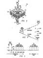
- FIG. 2there is illustrated a sketch of a nodal broadcast transmitter or system 12a.
- the nodal transmitter broadcast systems 11a and 13aare like system 12a illustrated in Fig. 2, but with the polarizations indicated in the sketches as +45° rotation and -45° (315°) rotation of Fig. 1. (Other orthogonal polarization may preferably be used, e.g., vertical and horizontal polarization).
- the system 12aincludes a post 35 for supporting a four-quadrant sectorized antenna complex system represented by 12b.
- the system 12aincludes a transmitter and receiver represented schematically by 21.
- Signals transmitted from system 12aare coupled from transmitter 21 to the nodal transmitter coverage or broadcast antenna system 12b comprised of four panel array antennas 31, 32, 33, and 34 via leads 22.
- the panel antennas 31-34are mounted to post 35 via supports 22a housing transmission lines 22.
- Each of these panel antennas 31-34comprises an array of transmitting antenna elements and receiving antenna elements as will be discussed in more detail later.
- Polarization of these antenna elements 30 for antenna system 12bis such that panels 31 and 33 for system 12b transmit 45° slant polarized waves (marked +45° in Fig. 1), while panels 32 and 34 for system 12b transmit -45° (315°) slant polarized waves (marked -45° slant in Fig. 1). See Fig. 1.
- These panel antennasfor example, produce a 90 degree beam width so that each of the panel antennas 31-34 covers approximately 90 degrees beam width and the polarization from these panel antennas 31-34 alternates from +45° slant polarization to -45° slant (315°) polarization to +45° slant polarization and then to -45° (315°) polarization about the center of the node on post 35.
- Thistherefore, provides a 360 degree pattern about the center of the node where the node broadcast transmitter is located.
- the adjacent nodes 11 and 13 on either side of node 12present orthogonal polarization.
- the panel antennas 31 and 33 in nodes 11 and 13produce -45° (315°) polarized signals and the panel antennas 32 and 34 in nodes 11 and 13 produce +45° polarized signals. Therefore, at the adjacent sectors of the nodes, that is where node 11 is adjacent to node 12, the polarizations are orthogonal, and where node 12 meets node 13 the polarization is orthogonal.
- the node broadcast transmitting antennas systems 11b, 12b and 13btransmit and communicate with receiving stations 41 scattered in the area of the nodes.
- Receiving station 41may be located anywhere in any of the nodes 11-13 and will receive the signal radiated from the antenna complex at the center of one of the nodes from the sectorized antenna system 20.
- the polarization of the receiving station 41would determine which sector it is receiving from.
- the receiving station 41a in Fig. 1 in node 12would be in the +45° slant polarized sector and receive +45° slant polarized signals from the panel antenna 33 of system 12b.
- Station 41b in node 12would receive preferably -45° (315°) slant polarized signals from the panel antenna 32 and not +45° polarized signals from panels 31 or 33 from system 12b or from panel 34 of system 11b.
- the receiving antenna 41clocated in the overlapping area of the pattern of 32 and 33, it is possible to receive both +45° polarized signals from panel antenna 33 and -45° (315°) slant polarized signals from panel antenna 32.
- a signal received from the face which is of the wrong polarization from the antenna 41would be 20 to 30 dB lower in power than the other face.
- the antenna of 41cwas -45° (315°) polarized it would receive the signal from panel antenna (+45° polarized) 33 of system 12b from 20 to 30 dB down from that of the 45° (315°) polarized signal from antenna 32 of system 12b.
- the systemis designed such that the signals from all four panels 31-34 are transmitting at the same carrier frequencies but may contain different information.
- the systemis dependent upon space (different coverage areas) as well as frequency and polarization diversity.
- the systemutilizes a four-quadrant sectorized antenna.
- the systemcould be of any even number of sectors such as two, four, eight, etc.
- the four-quadrant sectorized antenna discussed in Fig. 1has an azimuth pattern relatively flat over a plus and minus 45 degrees from the center (90° beam width) which is easy to implement and is, therefore, more easily implemented, for example on a building or a tower for mounting panel antennas.
- An octagon, or eight sector, antenna systemmay be practical in some cases, but receivers located a line drawn to the corners will be able to see more than two panels and, hence, see signals having the same polarization.
- the four sectoris the preferred embodiment where frequency re-use is required.
- the transmission to and from the central office 15, as stated previously,may include a microwave network with the microwave dish 18 coupled to a transceiver via an up/down converter 18a.
- the received signals from the central office 15are upconverted to millimeter waves and sent via the panel antennas and the received signals at the panel antennas are down converted to microwave frequencies and sent back to the central office 15 via antenna 18 or cables 16.
- WiFi frequenciese.g., millimeter frequency, may also be used to interconnect the nodes).
- the base station BS or the node transmittertransmits over a given sector as represented within the dashed lines in Fig. 3.
- the subscriber or remote stations RSare represented by RS #1, RS #2, etc. in Fig. 3.
- the transmission from the node directional base station antennas BS in the systemrepresents the down stream information and the signals from the remote stations RS represents the upstream signals in Figs. 3-5.
- the accuracy of frequency setting devicesbecomes difficult to achieve.
- Microwave systems that use digital modulationmust maintain good frequency tolerance.
- the remote station costsdominates the cost per subscriber. Remote stations need a low cost method for creating frequency reference.
- remote stationsmust have local oscillators with specific requirements on operating frequency and phase noise.
- the cost and complexity of local oscillatorscan add significantly to the cost of the remote stations.
- local oscillatorscreate a signal on a specific frequency by using either a high-Q component such as a crystal or by synchronizing to a signal with a known frequency.
- High-Q componentcan be expensive, especially if oscillators use ovens to stabilize frequency drifts over the operating temperature range.
- the signal strength at a remote stationvaries as a function of the distance between the base station and the remote station.
- designersuse automatic gain control (AGC) circuits to automatically adjust the gain of receivers and maximize the dynamic range of the payload signals.
- AGCautomatic gain control
- An AGC circuitrequires a gain setting control signal that payload demodulators often create.
- Remote station wiringroutes the control signal to a variable gain amplifier in the front end of the receiver and sets the gain at the receiver.
- the control signalbecomes expensive to route to the front end receives function. It is highly desirable to provide a system which avoids the wiring or telemetry for a control signal from the payload demodulator to the front end of the receiver.
- a communication systemwherein a receiver receives two pilot signals separated by a fixed frequency and utilizes the difference frequency from these two pilot signals to control the local oscillator frequency of the receiver.
- a point-to-multipoint communications systemthe point transmitter transmits a pilot signal to the remote multipoint receive stations and the remote receive stations utilize the received pilot signal to control the local oscillators of the receive stations.
- the point transmittertransmit a pilot signal to the remote multipoint receive stations and the amplitude level of the received pilot signal is detected and used to control the gain of the received signal.
- the detected amplitude levelsis used to control the gain of the transmitted signal from the remote station.
- a low cost method for creating a frequency referenceis provided by a pilot signal and in addition, a pilot signal with amplitude independent of the payload signals set the remote station gain and provides a range estimate.
- the remote station RSmay be like that illustrated in Fig. 4, which may include, for example, a roof unit assembly 50 with a diplexer 51 between the antenna 52 and remote station receive down converter 53 and the remote station up converter 54.
- the down converted signalsare coupled to a set top box and network interface 55 for doing distribution functions to a television example or via the modem to telephone or computer functions.
- the signal output from the telephone or computerwould be modulated onto an IF carrier sent through the interface modem distribution function box 55 to the up-converter 54 on the roof unit assembly, for example, which is then sent to the diplexer 51 to the antenna 52.
- the communications between a point base station BS and a remote station RSuse as a frequency band as illustrated in Fig. 5 containing upstream payload carriers (1), down stream payload carriers (2), and one or more pilot tones (3) (4) .
- the inventionuses a node base station (BS) to broadcast a reference pilot signal f3 that synchronizes the frequency of the local oscillators (LO) in the remote stations (RS).
- the communications bandcan have additional pilot signal f4.
- the frequency difference f3 - f4 between two pilot signalscan create reference signals with precise accuracy using simple circuitry.
- f3may be 28.1 GHz and f 4 may be 28 GHz leaving a 100 MHz difference signal.
- base stations (BS)broadcast to remote stations (RS) in a point-to-multipoint protocol.
- the remote station (RS)transmits to the base station BS.
- the downstream channelsmay be, for example, over frequency band 27.86 GHz to 28.50 GHz or 28.50 GHz to 29.5 GHz.
- the upstreamoperating, for example, over the frequency bands of 27.5 - 27.64 GHz or 29.38 to 29.5 GHz
- the pilot signalis positioned in frequency near the downstream carriers to allow common equipment (such as: transmitters, amplifiers, and antennas) to accommodate the pilot signal as well as the downstream payload carriers.
- the upstream and downstream signalsare preferably at the same polarization in a given sector but may be at different orthogonal polarization.
- the pilot signalhas a guard band (Fig. 5, Item 6) to keep interference from payload channels away from the pilot.
- the guard bandallows remote station circuitry to use simple filters and frequency recovery loops.
- the accuracy of the reference signalhas tight tolerances. For operation at say 28 GHz and with demodulators requiring payload carriers to be within 20 KHz, local oscillators require 0.7 parts-per-million frequency accuracy. Such oscillators are relatively expensive to implement without the use of a pilot signal.
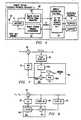
- the remote station RS 60receive section 53 and a transmit section 54.
- the receive section 61contains a variable attenuator 63, a mixer 64, a first narrow band pilot signal filter 65 at 28.1 GHz, a frequency lock loop 66, a local oscillator 67, a second narrow band pilot signal detector 68 at 28 GHz, a telemetry receiver and demodulator 73, and an automatic gain control 69.
- the polarized antenna inputis applied through variable gain amplifier 63 to mixer 64 which translates the frequency of the incoming radio frequency (RF) (input frequency band) signal to an intermediate frequency (IF) signal such as L-band (950 MHz to 1950 MHz).
- RFradio frequency
- IFintermediate frequency
- the pilot signal filter 65isolates the pilot signal from the downstream payload carriers.
- the frequency lock loop 66generates a reference signal for the local oscillators 67 and 70.
- the frequency of the reference signalis a function of the pilot signal frequency (Fig. 10).
- the reference signalmust be stable, be on a known frequency relative to the base station, and must have low phase noise.
- Fig. 7there is illustrated the one tone method wherein the received frequency F r is mixed with the local oscillator frequency F L0 at local oscillator (LO) 67 to produce a difference frequency F r - F L0 (960 MHz) which pilot signal (3) is divided by N at divider 66a to produce F r -F L 0 / N .
- a stable crystal controlled oscillator frequency (F refApprox. F r -F L 0 / N from the temperature compensated crystal oscillator(TCXO) 66b is subtracted by mixer 66c to get the voltage error Verr.
- a second pilot signal(Figs. 5 and 6, item 68) in place of a costly TCXO.
- the frequency difference between the signal 1 from filter 65 and signal 2 from filter 68can simplify precise frequency determination circuitry (Figs. 8).
- the base station transmitter BSsends downstream two pilot signals 3 and 4 at F r1 and F r2 respectively.
- the two receive pilot frequencies F r1 and Fr 2are received at the mixer 64 and these signals at F r1 - F LO and F r2 - F LO are passed through the separate narrow band filters 65 and 68 to mixer 66c and a derived reference frequency F ref is the difference frequency which is equal to (F r1 - F LO ) - (F r2 - F LO ) or Fr 1 - F r2 which is filtered by low pass filter 66d which passes the F ref frequency.
- This difference frequencyis then used to frequency lock the local oscillator 67 with the frequency input from the difference between the two pilot signals.
- the one filter 65can, for example, pass 28.1 GHz and filter 68 pass 28 GHz for a 100 MHz difference signal.
- the frequency lock loop circuit(Fig. 6, item 66) can also generate a reference signal for the transmit local oscillator (Fig. 6, item 70).
- the modulated IF carrier signalis up converted at mixer 71.
- the local oscillator 70 frequencycan use the same frequency lock loop 66 to control the transmit local oscillator 70. Therefore the downstream pilot signal or pilot signals controls the local oscillator for the upstream. It is anticipated that the IF frequency of the transmitter would be offset from the receive IF from mixer 64 to isolate the transmit RF from the receiver RF.
- the pilot signal amplitudeindicates receive signal strength.
- gain of the receive section 53can be increased to compensate for time varying path loss.
- Remote station RScan use the pilot to set the gain of the receiver.
- the pilot signal detector 78detects the amplitude of the pilot signal.
- An automatic gain control(AGC) (Fig. 6) uses the detected pilot signal amplitude to set the attenuation level for the variable gain amplifier (Fig. 6, item 63).
- the AGC(Fig. 6, item 69) can control the drive level to the transmit amplifier (Fig. 6, item 75)with the Variable Gain (Fig. 6, item 72) and thus control the output power of the RS transmitter 54.
- the telemetry detector(Fig. 6, item 73) recovers modulation on the pilot signal at filter 65 and passes the bit stream to the telemetry control function (Fig. 6, item 74)
- the telemetry controlcan perform such functions as roof unit addressing or ON/OFF control.
- the mixer 64 output payload signalsare passed on to the rest of the remote station RS receiver including the set top box and the subscriber equipment in the demodulators.
- phase noise of the IF signalmust be less than a specified level. Phase noise from the local oscillator contributes to the phase noise of the received signal.
- the spectrum of the local oscillator(Fig. 9) must be accurate in terms of frequency (F LO ) and phase noise.
- the phase noiseFor digitally modulated payload carriers, the phase noise must be typically less that -90 dBc at 10 KHz from F LO .
- the single and dual pilot tone approachproduce a local oscillator signal that has a phase noise dominated by the phase noise of the pilot tone. Because the pilot tone generator is located at a single point at the base station, the expense of a high purity (low phase noise) pilot signal generator is insignificant to per subscriber's cost.
- the pilot signalallows all down and upstream payload carriers to track a single master oscillator located at the base station thus eliminating the chance for frequency differences between the payload carriers.
- F refreference frequency
- the presence of a pilot signalenables transmission of the remote station. That is, if the remote station is not receiving a pilot signal (detected at detector 78) for whatever reason (such as pointing in the wrong direction ) the remote station RS is not allowed to transmit. This blocking is at gain control 72 with a signal from gain control 69. If on the other hand the pilot tone is weak, the gain is increased to reach the base station and if the pilot tone is strong, the gain is reduced.
- the payload carrierscan be turned off or changed in format without effecting the operation of the remote stations.
- the pilot signal amplitudeis also used to set the transmit power level of the remote station.
- a weak pilot signalcauses the transmitter to increase power.
- Applicants'utilize a pilot separated from payload carriers, one or more pilot tones broadcast to all remote stations, a pilot tone to synchronize the frequency of remote station LOs, a pilot tone as a low phase noise reference signal, a pilot tone at the signal strength indicator at a remote station, a pilot tone as a transmit interlock, and a pilot tone to send control telemetry to remote stations.
- the controlled local oscillatoris the second local oscillator.
- the received down stream RF signalsare filtered at band pass filter 100 centered at 28 GHz, amplified at variable gain amplifier 107 and mixer 103 with a local oscillator 101 which is selected at for example 25 to 28 GHz to produce the first IF of, for example, 1GHz may be 1-4 GHz dependent on the first local oscillator.
- the IF outputis then amplified at amplifier 109 and mixed at second mixer 110 with the second local oscillator 111 output.
- the second IF signal from mixer 110may be at the CATV frequency band (10MHz to 1GHz).
- the output from mixer 110is amplified by amplifier 113 and amplifier 115 and applied to the rest of receiver containing the distribution and subscriber equipment as in Fig. 4.
- a pilot signal detector 117is coupled to the output of amplifier 113 and includes a pilot signal filter and detector.
- the detected pilot frequencyis used as discussed above with the Automatic Frequency Control Circuit (AFC) 119 to control the frequency of the second local oscillator 111 and the amplitude level is used to control the gain of amplifiers 107, 109, and 113 via the automatic gain control circuit 121.
- the identification ID control 23may be used to require a password access to the received signals by modulating the pilot signal with telemetry.
Landscapes
- Engineering & Computer Science (AREA)
- Signal Processing (AREA)
- Computer Networks & Wireless Communication (AREA)
- Mobile Radio Communication Systems (AREA)
- Radio Relay Systems (AREA)
Abstract
Description
This invention relates to wireless point to multipointcommunication systems and more particularly to pilot signal methodfor controlling remote stations.
In a point-to-multipoint wireless communication system, acentral station communicates throughout a coverage area with multipleremote stations. The remote station would be located somewherewithin a node to communicate with a nodal transmitter receiver. Amore complete description of such a system for example may be apoint-to-multipoint system as described in Published European Patentdocument No.0, 715, 478. Referring to Fig. 1 from that application,there is illustrated thedistribution system network 10. Thisnetwork comprises a plurality of nodes, such as node 11 through 13covering a given combined area. For example, this area may cover afew city blocks only, but with hundreds of such nodes the area maycomprise an entire large city. Acentral office 15 would be, forexample, the central message center or source of programming fordistribution to the other nodes 11 through 13. Each of the nodeswould include a nodal broadcast transmitter or transmitter andreceiver system. This is represented by system 11a, 12a, and 13a inthe center of the nodes 11 through 13. The transmission from thecentral office 15 to the nodal broadcast transmitter systems 11a,12a, or 13a may be done by cabling in or around the city such asfiber optic telephone exchange cables represented here ascable 16between thecentral office 15 and the node transmitter systems 11a,12a, and 13a. This coupling may also be done using microwaveantennas such as usingantenna 17 from thecentral office 15communicating withantennas 18 at the center of the nodes at thesystems 11a, 12a, or 13a. This distribution may be implemented in avariety of other configurations well known in the state of the art.
Referring to Fig. 2, there is illustrated a sketch of a nodalbroadcast transmitter or system 12a. In the case of microwavedistribution from a central office, there is the microwave antennarepresented schematically by 18. The nodal transmitter broadcastsystems 11a and 13a are like system 12a illustrated in Fig. 2, butwith the polarizations indicated in the sketches as +45° rotation and-45° (315°) rotation of Fig. 1. (Other orthogonal polarization maypreferably be used, e.g., vertical and horizontal polarization). Thesystem 12a includes apost 35 for supporting a four-quadrantsectorized antenna complex system represented by 12b. The system 12aincludes a transmitter and receiver represented schematically by 21.Signals transmitted from system 12a are coupled fromtransmitter 21to the nodal transmitter coverage orbroadcast antenna system 12bcomprised of fourpanel array antennas leads 22. The panel antennas 31-34 are mounted topost 35 via supports 22ahousing transmission lines 22. Each of these panel antennas 31-34comprises an array of transmitting antenna elements and receivingantenna elements as will be discussed in more detail later.Polarization of theseantenna elements 30 forantenna system 12b issuch thatpanels system 12b transmit 45° slantpolarized waves (marked +45° in Fig. 1), whilepanels system 12b transmit -45° (315°) slant polarized waves (marked -45°slant in Fig. 1). See Fig. 1.
These panel antennas, for example, produce a 90 degree beamwidth so that each of the panel antennas 31-34 covers approximately90 degrees beam width and the polarization from these panel antennas31-34 alternates from +45° slant polarization to -45° slant (315°)polarization to +45° slant polarization and then to -45° (315°)polarization about the center of the node onpost 35. This,therefore, provides a 360 degree pattern about the center of the nodewhere the node broadcast transmitter is located.
Theadjacent nodes 11 and 13 on either side ofnode 12 presentorthogonal polarization. For example, thepanel antennas nodes 11 and 13 produce -45° (315°) polarized signals and thepanel antennas nodes 11 and 13 produce +45° polarizedsignals. Therefore, at the adjacent sectors of the nodes, that iswhere node 11 is adjacent tonode 12, the polarizations areorthogonal, and wherenode 12 meetsnode 13 the polarization isorthogonal. The node broadcast transmittingantennas systems 11b,12b and 13b transmit and communicate with receivingstations 41scattered in the area of the nodes.
Receivingstation 41 may be located anywhere in any of the nodes11-13 and will receive the signal radiated from the antenna complexat the center of one of the nodes from the sectorized antenna system20. The polarization of thereceiving station 41 would determinewhich sector it is receiving from. For example, the receivingstation 41a in Fig. 1 innode 12 would be in the +45° slant polarizedsector and receive +45° slant polarized signals from thepanelantenna 33 ofsystem 12b.Station 41b innode 12 would receivepreferably -45° (315°) slant polarized signals from thepanelantenna 32 and not +45° polarized signals frompanels system 12b or frompanel 34 of system 11b. For thereceiving antenna 41c, located in the overlapping area of the pattern of 32 and 33, itis possible to receive both +45° polarized signals frompanel antenna 33 and -45° (315°) slant polarized signals frompanel antenna 32.However, a signal received from the face which is of the wrongpolarization from theantenna 41 would be 20 to 30 dB lower in powerthan the other face. For example, if the antenna of 41c was -45°(315°) polarized it would receive the signal from panel antenna (+45°polarized) 33 ofsystem 12b from 20 to 30 dB down from that of the45° (315°) polarized signal fromantenna 32 ofsystem 12b.Similarly,stations nodes station 41e with a -45° (315°) polarizedantenna picks up signals frompanel antenna 32 ofsystem 12b. Thesignals frompanel antenna 34 of system 11b are 20 to 30 dB lowerthan those frompanel antenna 32 ofsystem 12b. Again the system may preferably be with the receiver antennas polarized vertical and/orhorizontal to match the nodal transmitting antennas.
The system is designed such that the signals from all fourpanels 31-34 are transmitting at the same carrier frequencies but maycontain different information. The system is dependent upon space(different coverage areas) as well as frequency and polarizationdiversity.
The system, as described herein, utilizes a four-quadrantsectorized antenna. However the system could be of any even numberof sectors such as two, four, eight, etc. The four-quadrantsectorized antenna discussed in Fig. 1 has an azimuth patternrelatively flat over a plus andminus 45 degrees from the center (90°beam width) which is easy to implement and is, therefore, more easilyimplemented, for example on a building or a tower for mounting panelantennas. An octagon, or eight sector, antenna system may bepractical in some cases, but receivers located a line drawn to thecorners will be able to see more than two panels and, hence, seesignals having the same polarization. Thus, the four sector is thepreferred embodiment where frequency re-use is required.
The transmission to and from thecentral office 15, as statedpreviously, may include a microwave network with themicrowave dish 18 coupled to a transceiver via an up/down converter 18a. Thereceived signals from thecentral office 15 are upconverted tomillimeter waves and sent via the panel antennas and the receivedsignals at the panel antennas are down converted to microwavefrequencies and sent back to thecentral office 15 viaantenna 18 orcables 16. (Other frequencies, e.g., millimeter frequency, may alsobe used to interconnect the nodes). This application is incorporatedherein by reference.
Viewing a particular sector, for example, the base station BS orthe node transmitter transmits over a given sector as representedwithin the dashed lines in Fig. 3. The subscriber or remote stationsRS are represented byRS # 1,RS # 2, etc. in Fig. 3. The transmissionfrom the node directional base station antennas BS in the system represents the down stream information and the signals from theremote stations RS represents the upstream signals in Figs. 3-5.
At the high operating frequencies of the microwave systems, suchas at the 27 - 30 GHz range, the accuracy of frequency settingdevices becomes difficult to achieve. Microwave systems that usedigital modulation must maintain good frequency tolerance. In apoint-to-multipoint communication system, the remote station costsdominates the cost per subscriber. Remote stations need a low costmethod for creating frequency reference.
For heterodyne receiver architectures, remote stations must havelocal oscillators with specific requirements on operating frequencyand phase noise. For digitally modulated payload signals atmicrowave operating frequencies, the cost and complexity of localoscillators can add significantly to the cost of the remote stations.Normally, local oscillators create a signal on a specific frequencyby using either a high-Q component such as a crystal or bysynchronizing to a signal with a known frequency. High-Q componentcan be expensive, especially if oscillators use ovens to stabilizefrequency drifts over the operating temperature range.
When multiple remote stations use closely spaced channels,errors in operating frequency can cause interference between thechannels.
The signal strength at a remote station varies as a function ofthe distance between the base station and the remote station.Traditionally designers use automatic gain control (AGC) circuits toautomatically adjust the gain of receivers and maximize the dynamicrange of the payload signals. An AGC circuit requires a gain settingcontrol signal that payload demodulators often create. Remotestation wiring routes the control signal to a variable gain amplifierin the front end of the receiver and sets the gain at the receiver.However, in a physical configuration where the payload demodulator isremotely located from the front end of the receiver the controlsignal becomes expensive to route to the front end receives function.It is highly desirable to provide a system which avoids the wiring or telemetry for a control signal from the payload demodulator to thefront end of the receiver.
In accordance with an embodiment of the present invention acommunication system is provided wherein a receiver receives twopilot signals separated by a fixed frequency and utilizes thedifference frequency from these two pilot signals to control thelocal oscillator frequency of the receiver.
In accordance with another embodiment of the present invention apoint-to-multipoint communications system the point transmittertransmits a pilot signal to the remote multipoint receive stationsand the remote receive stations utilize the received pilot signal tocontrol the local oscillators of the receive stations.
In accordance with another embodiment of the present invention,in a point-to-multipoint communications system, the point transmittertransmit a pilot signal to the remote multipoint receive stations andthe amplitude level of the received pilot signal is detected and usedto control the gain of the received signal.
In accordance with another embodiment the detected amplitudelevels is used to control the gain of the transmitted signal from theremote station.
These and other features of the invention that will be apparentto those skilled in the art from the following detailed descriptionof the invention, taken together with the accompanying drawings.
The present invention will now be further described by way ofexample, with reference to the accompanying drawings in which:
In accordance with one embodiment of the present invention a lowcost method for creating a frequency reference is provided by a pilotsignal and in addition, a pilot signal with amplitude independent ofthe payload signals set the remote station gain and provides a rangeestimate. The remote station RS may be like that illustrated in Fig.4, which may include, for example, aroof unit assembly 50 with adiplexer 51 between theantenna 52 and remote station receive downconverter 53 and the remote station upconverter 54. The downconverted signals are coupled to a set top box andnetwork interface 55 for doing distribution functions to a television example or viathe modem to telephone or computer functions. The signal output fromthe telephone or computer would be modulated onto an IF carrier sentthrough the interface modemdistribution function box 55 to the up-converter 54 on the roof unit assembly, for example, which is thensent to thediplexer 51 to theantenna 52. The communicationsbetween a point base station BS and a remote station RS use as afrequency band as illustrated in Fig. 5 containing upstream payload carriers (1), down stream payload carriers (2), and one or more pilottones (3) (4) .
As shown in Fig. 5, the invention uses a node base station (BS)to broadcast a reference pilot signal f3 that synchronizes thefrequency of the local oscillators (LO) in the remote stations (RS).As an option, the communications band can have additional pilotsignal f4. The frequency difference f3 - f4 between two pilot signalscan create reference signals with precise accuracy using simplecircuitry. For example f3 may be 28.1 GHz and f4 may be 28 GHzleaving a 100 MHz difference signal. For the downstream path, basestations (BS) broadcast to remote stations (RS) in a point-to-multipointprotocol. For the upstream path, the remote station (RS)transmits to the base station BS. The downstream channels may be,for example, over frequency band 27.86 GHz to 28.50 GHz or 28.50 GHzto 29.5 GHz. The upstream operating, for example, over the frequencybands of 27.5 - 27.64 GHz or 29.38 to 29.5 GHz
The pilot signal is positioned in frequency near the downstreamcarriers to allow common equipment (such as: transmitters,amplifiers, and antennas) to accommodate the pilot signal as well asthe downstream payload carriers. The upstream and downstream signalsare preferably at the same polarization in a given sector but may beat different orthogonal polarization. The pilot signal has a guardband (Fig. 5, Item 6) to keep interference from payload channels awayfrom the pilot. The guard band allows remote station circuitry touse simple filters and frequency recovery loops. The accuracy of thereference signal has tight tolerances. For operation at say 28 GHzand with demodulators requiring payload carriers to be within 20 KHz,local oscillators require 0.7 parts-per-million frequency accuracy.Such oscillators are relatively expensive to implement without theuse of a pilot signal.
Referring to Fig. 6, there is illustrated theremote station RS 60 receivesection 53 and a transmitsection 54. The receive section61 contains avariable attenuator 63, amixer 64, a first narrow bandpilot signal filter 65 at 28.1 GHz, afrequency lock loop 66, alocal oscillator 67, a second narrow bandpilot signal detector 68 at 28GHz, a telemetry receiver anddemodulator 73, and anautomatic gaincontrol 69. The transmitsection 54 contains a local oscillator 70(Ftransmit = FIF + FLO), amixer 71, a variable attenuator 72 a transmitpower amplifier 75, and transmit antenna 76. During receiveoperations, the polarized antenna input is applied throughvariablegain amplifier 63 tomixer 64 which translates the frequency of theincoming radio frequency (RF) (input frequency band) signal to anintermediate frequency (IF) signal such as L-band (950 MHz to 1950MHz). Thepilot signal filter 65 isolates the pilot signal from thedownstream payload carriers. Thefrequency lock loop 66 generates areference signal for thelocal oscillators
In accordance with Fig. 7 there is illustrated the one tonemethod wherein the received frequency Fr is mixed with the localoscillator frequency FL0 at local oscillator (LO) 67 to produce adifference frequency Fr - FL0 (960 MHz) which pilot signal (3) isdivided by N at divider 66a to produceFr-FL0 /N. A stable crystalcontrolled oscillator frequency (Fref = Approx.Fr-FL0 /N from thetemperature compensated crystal oscillator(TCXO) 66b is subtracted bymixer 66c to get the voltage error Verr. =Fr-FL0 /N-Fref · This voltageerror is applied to voltage controlledoscillator 67 to get thefrequency LO. If Verr increases then FLO decreases which tends tokeep FLO such that Fr - FLO equals precisely the pilot frequency (inthis case 960 MHz).
An option exists to use a second pilot signal (Figs. 5 and 6,item 68) in place of a costly TCXO. The frequency difference betweenthesignal 1 fromfilter 65 andsignal 2 fromfilter 68 can simplifyprecise frequency determination circuitry (Figs. 8). In accordance with the dual tone method of the system the base station transmitterBS sends downstream twopilot signals mixer 64 and these signals at Fr1 - FLO and Fr2 - FLOare passed through the separate narrow band filters 65 and 68 tomixer 66c and a derived reference frequency Fref is the differencefrequency which is equal to (Fr1 - FLO) - (Fr2 - FLO) or Fr1 - Fr2 whichis filtered bylow pass filter 66d which passes the Fref frequency.This difference frequency is then used to frequency lock thelocaloscillator 67 with the frequency input from the difference betweenthe two pilot signals. The onefilter 65 can, for example, pass 28.1GHz and filter 68 pass 28 GHz for a 100 MHz difference signal.
The frequency lock loop circuit (Fig. 6, item 66) can alsogenerate a reference signal for the transmit local oscillator (Fig.6, item 70). For the upstream signals from the remote stations RSthe modulated IF carrier signal is up converted atmixer 71. Thelocal oscillator 70 frequency can use the samefrequency lock loop 66to control the transmitlocal oscillator 70. Therefore thedownstream pilot signal or pilot signals controls the localoscillator for the upstream. It is anticipated that the IF frequencyof the transmitter would be offset from the receive IF frommixer 64to isolate the transmit RF from the receiver RF.
The pilot signal amplitude indicates receive signal strength.In the downstream path when an impairment such as rain occurs, thengain of the receivesection 53 can be increased to compensate fortime varying path loss. Remote station RS can use the pilot to setthe gain of the receiver.
The pilot signal detector 78 (Fig. 6) detects the amplitude ofthe pilot signal. An automatic gain control (AGC) (Fig. 6) uses thedetected pilot signal amplitude to set the attenuation level for thevariable gain amplifier (Fig. 6, item 63). The AGC (Fig. 6, item 69)can control the drive level to the transmit amplifier (Fig. 6, item75)with the Variable Gain (Fig. 6, item 72) and thus control theoutput power of theRS transmitter 54. The telemetry detector (Fig. 6, item 73) recovers modulation on the pilot signal atfilter 65 andpasses the bit stream to the telemetry control function (Fig. 6,item 74) The telemetry control can perform such functions as roofunit addressing or ON/OFF control. Themixer 64 output payloadsignals are passed on to the rest of the remote station RS receiverincluding the set top box and the subscriber equipment in thedemodulators.
For proper operation of the demodulator, phase noise of the IFsignal must be less than a specified level. Phase noise from thelocal oscillator contributes to the phase noise of the receivedsignal. The spectrum of the local oscillator (Fig. 9) must beaccurate in terms of frequency (FLO) and phase noise. For digitallymodulated payload carriers, the phase noise must be typically lessthat -90 dBc at 10 KHz from FLO .Both the single and dual pilot toneapproach produce a local oscillator signal that has a phase noisedominated by the phase noise of the pilot tone. Because the pilottone generator is located at a single point at the base station, theexpense of a high purity (low phase noise) pilot signal generator isinsignificant to per subscriber's cost.
For a multi-carrier payload it is important that all carrierstrack the frequency of a master oscillator at the base station BS.The pilot signal allows all down and upstream payload carriers totrack a single master oscillator located at the base station thuseliminating the chance for frequency differences between the payloadcarriers. By elementing reference frequency (Fref) differences, morepayload channels can be placed within a given operating band, becausespectrum need not be used for frequency differences between channels.
The presence of a pilot signal enables transmission of theremote station. That is, if the remote station is not receiving apilot signal (detected at detector 78) for whatever reason (such aspointing in the wrong direction ) the remote station RS is notallowed to transmit. This blocking is atgain control 72 with asignal fromgain control 69. If on the other hand the pilot tone is weak, the gain is increased to reach the base station and if thepilot tone is strong, the gain is reduced.
By placing the pilot signal separate from the payload carrier,the payload carriers can be turned off or changed in format withouteffecting the operation of the remote stations.
The pilot signal amplitude is also used to set the transmitpower level of the remote station. A weak pilot signal causes thetransmitter to increase power.
Applicants' utilize a pilot separated from payload carriers, oneor more pilot tones broadcast to all remote stations, a pilot tone tosynchronize the frequency of remote station LOs, a pilot tone as alow phase noise reference signal, a pilot tone at the signal strengthindicator at a remote station, a pilot tone as a transmit interlock,and a pilot tone to send control telemetry to remote stations.
Referring to Fig. 10 another embodiment is illustrated where thecontrolled local oscillator is the second local oscillator. Thereceived down stream RF signals are filtered atband pass filter 100centered at 28 GHz, amplified atvariable gain amplifier 107 andmixer 103 with alocal oscillator 101 which is selected at forexample 25 to 28 GHz to produce the first IF of, for example, 1GHzmay be 1-4 GHz dependent on the first local oscillator. The IFoutput is then amplified atamplifier 109 and mixed atsecond mixer 110 with the secondlocal oscillator 111 output. The second IFsignal frommixer 110 may be at the CATV frequency band (10MHz to1GHz). The output frommixer 110 is amplified byamplifier 113 andamplifier 115 and applied to the rest of receiver containing thedistribution and subscriber equipment as in Fig. 4. Apilot signaldetector 117 is coupled to the output ofamplifier 113 and includes apilot signal filter and detector. The detected pilot frequency isused as discussed above with the Automatic Frequency Control Circuit(AFC) 119 to control the frequency of the secondlocal oscillator 111and the amplitude level is used to control the gain ofamplifiers gain control circuit 121. Theidentification ID control 23 may be used to require a password access to the received signals by modulating the pilot signal withtelemetry.
Although the present invention and its advantages have beendescribed in detail, it should be understood that various changes,substitutions and alterations can be made herein without departingfrom the spirit and scope of the invention as defined by the appendedclaims.
Claims (15)
- A communications system comprising:a transmitter for transmitting transmitting a pair of pilotsignals separated by a fixed frequency;a receiver for receiving said pair of pilot signal, saidreceiver including means for recovering said fixed frequency fromsaid pair of pilot signals; and said receiver including localoscillator means controlled by said recovered fixed frequency.
- The communications system of Claim 1 wherein said meansfor recovering includes a mixer and filter.
- The communications system of Claim 1 or Claim 2, whereinsaid local oscillator is injection locked to said recovered fixedfrequency.
- A point-to-multipoint communications system comprising:a transmitter for transmitting a pair of pilot signals separatedby a fixed frequency;a receiver for receiving said pair of pilot signal, saidreceiver including means for recovering said fixed frequency fromsaid pair of pilot signals; and said receiver including localoscillator means controlled by said recovered fixed frequency.
- The communications system of Claim 4 wherein said meansfor recovering includes a mixer and filter.
- The communications system of Claim 4 or 5 wherein saidlocal oscillator is injection locked to said recovered fixedfrequency.
- A point-to-multipoint communications system comprising:a point transmitter for transmitting payload signals and a pilotsignal separate from said payload signals to multipoint receivestations;said multipoint receiver stations adapted for receiving saidpilot signal and for utilizing said received pilot signal to controlsaid receive stations local oscillator.
- The system of Claim 7, wherein said receiver stations eachinclude a receiver local oscillator for down converting said receivedsignal and a local reference oscillator;said detected pilot signal being divided by a factor toapproximate the frequency of said local reference oscillator;said divided pilot signal and said local reference oscillatorfrequencies being compared and a control signal equal to thedifference between said divided pilot signal frequency and the localreference frequency being generated and used for controlling thereceiver local oscillator.
- The system of Claim 8 wherein said receive stations aretransceiver stations and the transmitter local oscillator used forupconverting is controlled by said control signal.
- The system of Claim 9 wherein said receiver stationsinclude amplitude detector means for detecting the amplitude of thereceived pilot signal and means coupled to said detector means forcontrolling the gain of the received signals at the receiver stationsin proportion to the detected amplitude of the received signal.
- The system of Claim 10 wherein the transmitter outputamplitude is controlled by said detected amplitude of the receivedsignal.
- A point-to-multipoint communications system comprising:a nodal transmitter transmitting alternating polarizationsignals at the same frequency band about a node; said nodaltransmitter transmitting over each sector of the same polarization apilot signal;a plurality of transceivers located at multipoints about eachsector each adapted for receiving said pilot signal; andsaid transceivers responsive to said pilot signal forcontrolling the amplitude level of the incoming signal received atthe multipoint transceiver and for controlling the amplitude level ofthe transmitted signal from the multipoint transceivers back to thenodal transmitter.
- The system of Claim 12, wherein said transceiver isresponsive to said pilot signal for controlling the local oscillatorfrequency for both transmit and receive.
- A point-to-multipoint communications system comprising:a nodal transmitter for transmitting alternating polarizationsignal at the same frequency band about a node; said nodaltransmitter transmitting over each sector of the same polarization apair of pilot signals separated by a fixed frequency;a plurality of transceivers located at multipoints about eachsector each adapted for receiving said pilot signals; andsaid transceivers responsive to one of said pair of pilotsignals for controlling the amplitude level of the incoming signalreceived at the multipoint transceiver and for controlling theamplitude level of the transmitted signal from the multipointtransceivers back to the nodal transmitter.
- The system of Claim 14, wherein said transceiver isresponsive to said pair of pilot signals for controlling the localoscillator frequency for both transmit and receive.
Applications Claiming Priority (2)
| Application Number | Priority Date | Filing Date | Title |
|---|---|---|---|
| US3434396P | 1996-12-23 | 1996-12-23 | |
| US34343P | 1996-12-23 |
Publications (2)
| Publication Number | Publication Date |
|---|---|
| EP0851618A2true EP0851618A2 (en) | 1998-07-01 |
| EP0851618A3 EP0851618A3 (en) | 2001-10-04 |
Family
ID=21875839
Family Applications (1)
| Application Number | Title | Priority Date | Filing Date |
|---|---|---|---|
| EP97310547AWithdrawnEP0851618A3 (en) | 1996-12-23 | 1997-12-23 | Method and system for controlling remote multipoint stations |
Country Status (4)
| Country | Link |
|---|---|
| US (1) | US6212397B1 (en) |
| EP (1) | EP0851618A3 (en) |
| JP (1) | JPH10200473A (en) |
| KR (1) | KR19980064516A (en) |
Cited By (57)
| Publication number | Priority date | Publication date | Assignee | Title |
|---|---|---|---|---|
| WO1999023759A1 (en)* | 1997-11-03 | 1999-05-14 | Wireless Systems International Limited | Apparatus for and method of synchronising oscillators within a data communication system |
| EP0949770A1 (en)* | 1998-04-09 | 1999-10-13 | BetaResearch Gesellschaft für Entwicklung und Vermarktung digitaler Infrastrukturen mbH | Bidirectional broadcasting system |
| US6212397B1 (en)* | 1996-12-23 | 2001-04-03 | Texas Instruments Incorporated | Method and system for controlling remote multipoint stations |
| WO2002025966A1 (en)* | 2000-09-25 | 2002-03-28 | Ogier Electronics Limited | Incoherent beacons to provide a spectrally efficient frequency reference in point to multipoint radio systems |
| EP1659712A1 (en)* | 2004-11-17 | 2006-05-24 | Boris Sijanec | Microwave hybrid bidirectional distribution and communication system |
| US8532492B2 (en) | 2009-02-03 | 2013-09-10 | Corning Cable Systems Llc | Optical fiber-based distributed antenna systems, components, and related methods for calibration thereof |
| US8639121B2 (en) | 2009-11-13 | 2014-01-28 | Corning Cable Systems Llc | Radio-over-fiber (RoF) system for protocol-independent wired and/or wireless communication |
| US8644844B2 (en) | 2007-12-20 | 2014-02-04 | Corning Mobileaccess Ltd. | Extending outdoor location based services and applications into enclosed areas |
| US8718478B2 (en) | 2007-10-12 | 2014-05-06 | Corning Cable Systems Llc | Hybrid wireless/wired RoF transponder and hybrid RoF communication system using same |
| US8867919B2 (en) | 2007-07-24 | 2014-10-21 | Corning Cable Systems Llc | Multi-port accumulator for radio-over-fiber (RoF) wireless picocellular systems |
| US8873585B2 (en) | 2006-12-19 | 2014-10-28 | Corning Optical Communications Wireless Ltd | Distributed antenna system for MIMO technologies |
| US8983301B2 (en) | 2010-03-31 | 2015-03-17 | Corning Optical Communications LLC | Localization services in optical fiber-based distributed communications components and systems, and related methods |
| US9158864B2 (en) | 2012-12-21 | 2015-10-13 | Corning Optical Communications Wireless Ltd | Systems, methods, and devices for documenting a location of installed equipment |
| US9178635B2 (en) | 2014-01-03 | 2015-11-03 | Corning Optical Communications Wireless Ltd | Separation of communication signal sub-bands in distributed antenna systems (DASs) to reduce interference |
| US9184843B2 (en) | 2011-04-29 | 2015-11-10 | Corning Optical Communications LLC | Determining propagation delay of communications in distributed antenna systems, and related components, systems, and methods |
| US9185674B2 (en) | 2010-08-09 | 2015-11-10 | Corning Cable Systems Llc | Apparatuses, systems, and methods for determining location of a mobile device(s) in a distributed antenna system(s) |
| US9240835B2 (en) | 2011-04-29 | 2016-01-19 | Corning Optical Communications LLC | Systems, methods, and devices for increasing radio frequency (RF) power in distributed antenna systems |
| US9247543B2 (en) | 2013-07-23 | 2016-01-26 | Corning Optical Communications Wireless Ltd | Monitoring non-supported wireless spectrum within coverage areas of distributed antenna systems (DASs) |
| US9258052B2 (en) | 2012-03-30 | 2016-02-09 | Corning Optical Communications LLC | Reducing location-dependent interference in distributed antenna systems operating in multiple-input, multiple-output (MIMO) configuration, and related components, systems, and methods |
| US9319138B2 (en) | 2010-02-15 | 2016-04-19 | Corning Optical Communications LLC | Dynamic cell bonding (DCB) for radio-over-fiber (RoF)-based networks and communication systems and related methods |
| US9357551B2 (en) | 2014-05-30 | 2016-05-31 | Corning Optical Communications Wireless Ltd | Systems and methods for simultaneous sampling of serial digital data streams from multiple analog-to-digital converters (ADCS), including in distributed antenna systems |
| US9385810B2 (en) | 2013-09-30 | 2016-07-05 | Corning Optical Communications Wireless Ltd | Connection mapping in distributed communication systems |
| US9420542B2 (en) | 2014-09-25 | 2016-08-16 | Corning Optical Communications Wireless Ltd | System-wide uplink band gain control in a distributed antenna system (DAS), based on per band gain control of remote uplink paths in remote units |
| US9419712B2 (en) | 2010-10-13 | 2016-08-16 | Ccs Technology, Inc. | Power management for remote antenna units in distributed antenna systems |
| US9455784B2 (en) | 2012-10-31 | 2016-09-27 | Corning Optical Communications Wireless Ltd | Deployable wireless infrastructures and methods of deploying wireless infrastructures |
| US9497706B2 (en) | 2013-02-20 | 2016-11-15 | Corning Optical Communications Wireless Ltd | Power management in distributed antenna systems (DASs), and related components, systems, and methods |
| US9509133B2 (en) | 2014-06-27 | 2016-11-29 | Corning Optical Communications Wireless Ltd | Protection of distributed antenna systems |
| US9525472B2 (en) | 2014-07-30 | 2016-12-20 | Corning Incorporated | Reducing location-dependent destructive interference in distributed antenna systems (DASS) operating in multiple-input, multiple-output (MIMO) configuration, and related components, systems, and methods |
| US9531452B2 (en) | 2012-11-29 | 2016-12-27 | Corning Optical Communications LLC | Hybrid intra-cell / inter-cell remote unit antenna bonding in multiple-input, multiple-output (MIMO) distributed antenna systems (DASs) |
| US9590733B2 (en) | 2009-07-24 | 2017-03-07 | Corning Optical Communications LLC | Location tracking using fiber optic array cables and related systems and methods |
| US9602210B2 (en) | 2014-09-24 | 2017-03-21 | Corning Optical Communications Wireless Ltd | Flexible head-end chassis supporting automatic identification and interconnection of radio interface modules and optical interface modules in an optical fiber-based distributed antenna system (DAS) |
| US9621293B2 (en) | 2012-08-07 | 2017-04-11 | Corning Optical Communications Wireless Ltd | Distribution of time-division multiplexed (TDM) management services in a distributed antenna system, and related components, systems, and methods |
| US9648580B1 (en) | 2016-03-23 | 2017-05-09 | Corning Optical Communications Wireless Ltd | Identifying remote units in a wireless distribution system (WDS) based on assigned unique temporal delay patterns |
| US9647758B2 (en) | 2012-11-30 | 2017-05-09 | Corning Optical Communications Wireless Ltd | Cabling connectivity monitoring and verification |
| US9653861B2 (en) | 2014-09-17 | 2017-05-16 | Corning Optical Communications Wireless Ltd | Interconnection of hardware components |
| US9661781B2 (en) | 2013-07-31 | 2017-05-23 | Corning Optical Communications Wireless Ltd | Remote units for distributed communication systems and related installation methods and apparatuses |
| US9673904B2 (en) | 2009-02-03 | 2017-06-06 | Corning Optical Communications LLC | Optical fiber-based distributed antenna systems, components, and related methods for calibration thereof |
| US9681313B2 (en) | 2015-04-15 | 2017-06-13 | Corning Optical Communications Wireless Ltd | Optimizing remote antenna unit performance using an alternative data channel |
| US9685782B2 (en) | 2010-11-24 | 2017-06-20 | Corning Optical Communications LLC | Power distribution module(s) capable of hot connection and/or disconnection for distributed antenna systems, and related power units, components, and methods |
| US9699723B2 (en) | 2010-10-13 | 2017-07-04 | Ccs Technology, Inc. | Local power management for remote antenna units in distributed antenna systems |
| US9715157B2 (en) | 2013-06-12 | 2017-07-25 | Corning Optical Communications Wireless Ltd | Voltage controlled optical directional coupler |
| US9730228B2 (en) | 2014-08-29 | 2017-08-08 | Corning Optical Communications Wireless Ltd | Individualized gain control of remote uplink band paths in a remote unit in a distributed antenna system (DAS), based on combined uplink power level in the remote unit |
| US9729267B2 (en) | 2014-12-11 | 2017-08-08 | Corning Optical Communications Wireless Ltd | Multiplexing two separate optical links with the same wavelength using asymmetric combining and splitting |
| US9729251B2 (en) | 2012-07-31 | 2017-08-08 | Corning Optical Communications LLC | Cooling system control in distributed antenna systems |
| US9775123B2 (en) | 2014-03-28 | 2017-09-26 | Corning Optical Communications Wireless Ltd. | Individualized gain control of uplink paths in remote units in a distributed antenna system (DAS) based on individual remote unit contribution to combined uplink power |
| US9781553B2 (en) | 2012-04-24 | 2017-10-03 | Corning Optical Communications LLC | Location based services in a distributed communication system, and related components and methods |
| US9807700B2 (en) | 2015-02-19 | 2017-10-31 | Corning Optical Communications Wireless Ltd | Offsetting unwanted downlink interference signals in an uplink path in a distributed antenna system (DAS) |
| US9948349B2 (en) | 2015-07-17 | 2018-04-17 | Corning Optical Communications Wireless Ltd | IOT automation and data collection system |
| US9974074B2 (en) | 2013-06-12 | 2018-05-15 | Corning Optical Communications Wireless Ltd | Time-division duplexing (TDD) in distributed communications systems, including distributed antenna systems (DASs) |
| US10128951B2 (en) | 2009-02-03 | 2018-11-13 | Corning Optical Communications LLC | Optical fiber-based distributed antenna systems, components, and related methods for monitoring and configuring thereof |
| US10136200B2 (en) | 2012-04-25 | 2018-11-20 | Corning Optical Communications LLC | Distributed antenna system architectures |
| US10236924B2 (en) | 2016-03-31 | 2019-03-19 | Corning Optical Communications Wireless Ltd | Reducing out-of-channel noise in a wireless distribution system (WDS) |
| US10257056B2 (en) | 2012-11-28 | 2019-04-09 | Corning Optical Communications LLC | Power management for distributed communication systems, and related components, systems, and methods |
| US10455497B2 (en) | 2013-11-26 | 2019-10-22 | Corning Optical Communications LLC | Selective activation of communications services on power-up of a remote unit(s) in a wireless communication system (WCS) based on power consumption |
| US10560214B2 (en) | 2015-09-28 | 2020-02-11 | Corning Optical Communications LLC | Downlink and uplink communication path switching in a time-division duplex (TDD) distributed antenna system (DAS) |
| US10992484B2 (en) | 2013-08-28 | 2021-04-27 | Corning Optical Communications LLC | Power management for distributed communication systems, and related components, systems, and methods |
| US11296504B2 (en) | 2010-11-24 | 2022-04-05 | Corning Optical Communications LLC | Power distribution module(s) capable of hot connection and/or disconnection for wireless communication systems, and related power units, components, and methods |
Families Citing this family (25)
| Publication number | Priority date | Publication date | Assignee | Title |
|---|---|---|---|---|
| US6415150B1 (en)* | 1998-09-11 | 2002-07-02 | Ameritech Corporation | System and method for providing telecommunications service using a wireless link |
| US6581208B1 (en)* | 1999-02-19 | 2003-06-17 | Masprodenkoh Kabushikikaisha | Up-converter and down-converter for in-building CATV system |
| US6615407B1 (en)* | 1999-02-19 | 2003-09-02 | Masprodenkoh Kabushikikaisha | In-building CATV system, and up-converter and down-converter for use therein |
| US6456823B1 (en) | 1999-06-25 | 2002-09-24 | Raytheon Company | System and method for recovering a pilot tone in a local multipoint distribution system signal |
| US7047555B1 (en)* | 1999-07-23 | 2006-05-16 | Masprodenkoh Kabushikikaisha | In-building CATV system, down-converter, up-converter and amplifier |
| EP1085676B1 (en)* | 1999-09-16 | 2014-10-22 | Alcatel Lucent | Method of controlling power in a point to multipoint communication network and system for carrying out said method |
| US8363757B1 (en)* | 1999-10-12 | 2013-01-29 | Qualcomm Incorporated | Method and apparatus for eliminating the effects of frequency offsets in a digital communication system |
| AU2001289298A1 (en)* | 2000-03-30 | 2001-10-15 | Coaxmedia, Inc. | Architecture and method for automatic distributed gain control for modem communications over passive multipoint networks |
| WO2001093475A1 (en)* | 2000-05-25 | 2001-12-06 | Passover, Inc. | Mobile radio service over catv network |
| US7493143B2 (en)* | 2001-05-07 | 2009-02-17 | Qualcomm Incorporated | Method and system for utilizing polarization reuse in wireless communications |
| CA2347927A1 (en)* | 2001-05-16 | 2002-11-16 | Telecommunications Research Laboratories | Centralized synchronization for wireless networks |
| US6563893B2 (en)* | 2001-05-17 | 2003-05-13 | Ut-Battelle, Llc | Carrier-frequency synchronization system for improved amplitude modulation and television broadcast reception |
| US7587017B2 (en)* | 2001-05-17 | 2009-09-08 | Ut-Battelle, Llc | Carrier phase synchronization system for improved amplitude modulation and television broadcast reception |
| US7088958B2 (en)* | 2001-06-19 | 2006-08-08 | Intersil Americas Inc. | Remote power amplifier linearization |
| KR100915275B1 (en)* | 2001-11-05 | 2009-09-03 | 가부시키가이샤 히타치세이사쿠쇼 | Wireless communication system and communication control method therefor and wireless communication station |
| US7107027B2 (en)* | 2001-11-29 | 2006-09-12 | Intel Corporation | Distributed transmitter automatic gain control |
| US7248625B2 (en)* | 2002-09-05 | 2007-07-24 | Silicon Storage Technology, Inc. | Compensation of I-Q imbalance in digital transceivers |
| JP2005283543A (en)* | 2004-03-31 | 2005-10-13 | Tau Giken:Kk | Suspicious person detection system |
| ES2454198T3 (en)* | 2006-07-07 | 2014-04-09 | E-Blink | Synchronization procedure of two electronic devices of a wireless link, particularly of a mobile telephone network and implementation system of this procedure |
| US8457562B2 (en)* | 2007-03-27 | 2013-06-04 | Adc Telecommunications, Inc. | Digitized reverse link monitor |
| EP2228920B1 (en)* | 2009-03-12 | 2013-05-15 | Alcatel Lucent | Antenna synchronization for coherent network MIMO |
| FR2956934B1 (en) | 2010-02-26 | 2012-09-28 | Blink E | METHOD AND DEVICE FOR TRANSMITTING / RECEIVING ELECTROMAGNETIC SIGNALS RECEIVED / EMITTED ON ONE OR MORE FIRST FREQUENCY BANDS. |
| JP4846864B2 (en)* | 2010-06-14 | 2011-12-28 | 株式会社東芝 | Signal transmission apparatus and signal transmission method |
| FR2990315B1 (en) | 2012-05-04 | 2014-06-13 | Blink E | METHOD FOR TRANSMITTING INFORMATION BETWEEN A TRANSMITTING UNIT AND A RECEIVING UNIT |
| US9785175B2 (en) | 2015-03-27 | 2017-10-10 | Corning Optical Communications Wireless, Ltd. | Combining power from electrically isolated power paths for powering remote units in a distributed antenna system(s) (DASs) |
Citations (1)
| Publication number | Priority date | Publication date | Assignee | Title |
|---|---|---|---|---|
| US4500921A (en)* | 1981-07-23 | 1985-02-19 | Clarion Co., Ltd. | AGC Arrangement for a television system |
Family Cites Families (23)
| Publication number | Priority date | Publication date | Assignee | Title |
|---|---|---|---|---|
| US3970965A (en)* | 1975-03-26 | 1976-07-20 | The United States Of America As Represented By The Secretary Of The Navy | Injection locked Josephson oscillator systems |
| US4034296A (en)* | 1975-12-29 | 1977-07-05 | Motorola, Inc. | Omni-frequency pilot system |
| US4063188A (en)* | 1976-03-22 | 1977-12-13 | Rca Corporation | Injection-locked voltage controlled oscillators |
| US4165486A (en)* | 1976-12-16 | 1979-08-21 | Alps Electric Co., Ltd. | Single sideband transceiver |
| US4218772A (en)* | 1978-08-28 | 1980-08-19 | The United States Of America As Represented By The Secretary Of The Army | Locked-oscillator repeater with modulation frequency feedback |
| US4479256A (en)* | 1982-10-04 | 1984-10-23 | Ael Microtel, Limited | Two pilot frequency control for communication systems |
| US4466130A (en)* | 1982-10-04 | 1984-08-14 | Ael Microtel Limited | Two pilot frequency control for communication systems |
| US4541118A (en)* | 1983-12-22 | 1985-09-10 | Motorola, Inc. | SSB System with pilot coded squelch |
| US4618996A (en)* | 1984-04-24 | 1986-10-21 | Avnet, Inc. | Dual pilot phase lock loop for radio frequency transmission |
| US5199045A (en)* | 1987-06-09 | 1993-03-30 | Canon Kabushiki Kaisha | Communication apparatus |
| US5133081A (en)* | 1989-11-03 | 1992-07-21 | Mayo Scott T | Remotely controllable message broadcast system including central programming station, remote message transmitters and repeaters |
| US5109532A (en)* | 1990-01-30 | 1992-04-28 | General Instrument Corporation | Elimination of phase noise and drift incident to up and down conversion in a broadcast communication system |
| US5802173A (en)* | 1991-01-15 | 1998-09-01 | Rogers Cable Systems Limited | Radiotelephony system |
| CA2071421C (en)* | 1991-06-19 | 2000-08-08 | Yoshiaki Kumagai | Automatic frequency control circuit |
| DE4122004C2 (en)* | 1991-07-03 | 1994-01-13 | Rundfunk Betriebstechnik Gmbh | Method for transmitting a manipulated variable that changes over time |
| DE4319830A1 (en)* | 1993-06-16 | 1995-03-09 | Philips Patentverwaltung | CDMA transmission system |
| JPH07221546A (en)* | 1994-01-28 | 1995-08-18 | Nippon Telegr & Teleph Corp <Ntt> | Injection locked oscillator |
| US5559789A (en)* | 1994-01-31 | 1996-09-24 | Matsushita Electric Industrial Co., Ltd. | CDMA/TDD Radio Communication System |
| US6006069A (en)* | 1994-11-28 | 1999-12-21 | Bosch Telecom Gmbh | Point-to-multipoint communications system |
| US5566366A (en)* | 1994-11-30 | 1996-10-15 | Motorola, Inc. | Method of power conservation in a data communications system |
| US5627499A (en)* | 1995-10-13 | 1997-05-06 | Pacific Communication Sciences, Inc. | Digital modulator and upconverter having single-bit delta-sigma data converters |
| US5867485A (en)* | 1996-06-14 | 1999-02-02 | Bellsouth Corporation | Low power microcellular wireless drop interactive network |
| US6212397B1 (en)* | 1996-12-23 | 2001-04-03 | Texas Instruments Incorporated | Method and system for controlling remote multipoint stations |
- 1997
- 1997-12-22USUS08/996,270patent/US6212397B1/ennot_activeExpired - Lifetime
- 1997-12-23EPEP97310547Apatent/EP0851618A3/ennot_activeWithdrawn
- 1997-12-23KRKR1019970072505Apatent/KR19980064516A/ennot_activeWithdrawn
- 1997-12-24JPJP9370225Apatent/JPH10200473A/enactivePending
Patent Citations (1)
| Publication number | Priority date | Publication date | Assignee | Title |
|---|---|---|---|---|
| US4500921A (en)* | 1981-07-23 | 1985-02-19 | Clarion Co., Ltd. | AGC Arrangement for a television system |
Cited By (111)
| Publication number | Priority date | Publication date | Assignee | Title |
|---|---|---|---|---|
| US6212397B1 (en)* | 1996-12-23 | 2001-04-03 | Texas Instruments Incorporated | Method and system for controlling remote multipoint stations |
| WO1999023759A1 (en)* | 1997-11-03 | 1999-05-14 | Wireless Systems International Limited | Apparatus for and method of synchronising oscillators within a data communication system |
| EP0949770A1 (en)* | 1998-04-09 | 1999-10-13 | BetaResearch Gesellschaft für Entwicklung und Vermarktung digitaler Infrastrukturen mbH | Bidirectional broadcasting system |
| WO1999053636A1 (en)* | 1998-04-09 | 1999-10-21 | Betaresearch Gesellschaft Für Entwicklung Und Vermarktung Digitaler Infrastrukturen Mbh | Bidirectional broadcasting system |
| WO2002025966A1 (en)* | 2000-09-25 | 2002-03-28 | Ogier Electronics Limited | Incoherent beacons to provide a spectrally efficient frequency reference in point to multipoint radio systems |
| EP1659712A1 (en)* | 2004-11-17 | 2006-05-24 | Boris Sijanec | Microwave hybrid bidirectional distribution and communication system |
| WO2006054955A1 (en)* | 2004-11-17 | 2006-05-26 | Boris Sijanec | Microwave hybrid bidirectional distribution communication system |
| US8873585B2 (en) | 2006-12-19 | 2014-10-28 | Corning Optical Communications Wireless Ltd | Distributed antenna system for MIMO technologies |
| US9130613B2 (en) | 2006-12-19 | 2015-09-08 | Corning Optical Communications Wireless Ltd | Distributed antenna system for MIMO technologies |
| US8867919B2 (en) | 2007-07-24 | 2014-10-21 | Corning Cable Systems Llc | Multi-port accumulator for radio-over-fiber (RoF) wireless picocellular systems |
| US8718478B2 (en) | 2007-10-12 | 2014-05-06 | Corning Cable Systems Llc | Hybrid wireless/wired RoF transponder and hybrid RoF communication system using same |
| US8644844B2 (en) | 2007-12-20 | 2014-02-04 | Corning Mobileaccess Ltd. | Extending outdoor location based services and applications into enclosed areas |
| US10128951B2 (en) | 2009-02-03 | 2018-11-13 | Corning Optical Communications LLC | Optical fiber-based distributed antenna systems, components, and related methods for monitoring and configuring thereof |
| US9900097B2 (en) | 2009-02-03 | 2018-02-20 | Corning Optical Communications LLC | Optical fiber-based distributed antenna systems, components, and related methods for calibration thereof |
| US10153841B2 (en) | 2009-02-03 | 2018-12-11 | Corning Optical Communications LLC | Optical fiber-based distributed antenna systems, components, and related methods for calibration thereof |
| US9112611B2 (en) | 2009-02-03 | 2015-08-18 | Corning Optical Communications LLC | Optical fiber-based distributed antenna systems, components, and related methods for calibration thereof |
| US9673904B2 (en) | 2009-02-03 | 2017-06-06 | Corning Optical Communications LLC | Optical fiber-based distributed antenna systems, components, and related methods for calibration thereof |
| US8532492B2 (en) | 2009-02-03 | 2013-09-10 | Corning Cable Systems Llc | Optical fiber-based distributed antenna systems, components, and related methods for calibration thereof |
| US9590733B2 (en) | 2009-07-24 | 2017-03-07 | Corning Optical Communications LLC | Location tracking using fiber optic array cables and related systems and methods |
| US10070258B2 (en) | 2009-07-24 | 2018-09-04 | Corning Optical Communications LLC | Location tracking using fiber optic array cables and related systems and methods |
| US9729238B2 (en) | 2009-11-13 | 2017-08-08 | Corning Optical Communications LLC | Radio-over-fiber (ROF) system for protocol-independent wired and/or wireless communication |
| US9219879B2 (en) | 2009-11-13 | 2015-12-22 | Corning Optical Communications LLC | Radio-over-fiber (ROF) system for protocol-independent wired and/or wireless communication |
| US9485022B2 (en) | 2009-11-13 | 2016-11-01 | Corning Optical Communications LLC | Radio-over-fiber (ROF) system for protocol-independent wired and/or wireless communication |
| US8639121B2 (en) | 2009-11-13 | 2014-01-28 | Corning Cable Systems Llc | Radio-over-fiber (RoF) system for protocol-independent wired and/or wireless communication |
| US9319138B2 (en) | 2010-02-15 | 2016-04-19 | Corning Optical Communications LLC | Dynamic cell bonding (DCB) for radio-over-fiber (RoF)-based networks and communication systems and related methods |
| US9967032B2 (en) | 2010-03-31 | 2018-05-08 | Corning Optical Communications LLC | Localization services in optical fiber-based distributed communications components and systems, and related methods |
| US8983301B2 (en) | 2010-03-31 | 2015-03-17 | Corning Optical Communications LLC | Localization services in optical fiber-based distributed communications components and systems, and related methods |
| US9913094B2 (en) | 2010-08-09 | 2018-03-06 | Corning Optical Communications LLC | Apparatuses, systems, and methods for determining location of a mobile device(s) in a distributed antenna system(s) |
| US9185674B2 (en) | 2010-08-09 | 2015-11-10 | Corning Cable Systems Llc | Apparatuses, systems, and methods for determining location of a mobile device(s) in a distributed antenna system(s) |
| US11653175B2 (en) | 2010-08-09 | 2023-05-16 | Corning Optical Communications LLC | Apparatuses, systems, and methods for determining location of a mobile device(s) in a distributed antenna system(s) |
| US10448205B2 (en) | 2010-08-09 | 2019-10-15 | Corning Optical Communications LLC | Apparatuses, systems, and methods for determining location of a mobile device(s) in a distributed antenna system(s) |
| US12160789B2 (en) | 2010-08-09 | 2024-12-03 | Corning Optical Communications LLC | Apparatuses, systems, and methods for determining location of a mobile device(s) in a distributed antenna system(s) |
| US10959047B2 (en) | 2010-08-09 | 2021-03-23 | Corning Optical Communications LLC | Apparatuses, systems, and methods for determining location of a mobile device(s) in a distributed antenna system(s) |
| US10420025B2 (en) | 2010-10-13 | 2019-09-17 | Corning Optical Communications LLC | Local power management for remote antenna units in distributed antenna systems |
| US11212745B2 (en) | 2010-10-13 | 2021-12-28 | Corning Optical Communications LLC | Power management for remote antenna units in distributed antenna systems |
| US11178609B2 (en) | 2010-10-13 | 2021-11-16 | Corning Optical Communications LLC | Power management for remote antenna units in distributed antenna systems |
| US11671914B2 (en) | 2010-10-13 | 2023-06-06 | Corning Optical Communications LLC | Power management for remote antenna units in distributed antenna systems |
| US10045288B2 (en) | 2010-10-13 | 2018-08-07 | Corning Optical Communications LLC | Power management for remote antenna units in distributed antenna systems |
| US11224014B2 (en) | 2010-10-13 | 2022-01-11 | Corning Optical Communications LLC | Power management for remote antenna units in distributed antenna systems |
| US10104610B2 (en) | 2010-10-13 | 2018-10-16 | Corning Optical Communications LLC | Local power management for remote antenna units in distributed antenna systems |
| US10425891B2 (en) | 2010-10-13 | 2019-09-24 | Corning Optical Communications LLC | Power management for remote antenna units in distributed antenna systems |
| US9699723B2 (en) | 2010-10-13 | 2017-07-04 | Ccs Technology, Inc. | Local power management for remote antenna units in distributed antenna systems |
| US9419712B2 (en) | 2010-10-13 | 2016-08-16 | Ccs Technology, Inc. | Power management for remote antenna units in distributed antenna systems |
| US11715949B2 (en) | 2010-11-24 | 2023-08-01 | Corning Optical Communications LLC | Power distribution module(s) capable of hot connection and/or disconnection for wireless communication systems, and related power units, components, and methods |
| US10454270B2 (en) | 2010-11-24 | 2019-10-22 | Corning Optical Communicatons LLC | Power distribution module(s) capable of hot connection and/or disconnection for wireless communication systems, and related power units, components, and methods |
| US11296504B2 (en) | 2010-11-24 | 2022-04-05 | Corning Optical Communications LLC | Power distribution module(s) capable of hot connection and/or disconnection for wireless communication systems, and related power units, components, and methods |
| US9685782B2 (en) | 2010-11-24 | 2017-06-20 | Corning Optical Communications LLC | Power distribution module(s) capable of hot connection and/or disconnection for distributed antenna systems, and related power units, components, and methods |
| US11114852B2 (en) | 2010-11-24 | 2021-09-07 | Corning Optical Communications LLC | Power distribution module(s) capable of hot connection and/or disconnection for wireless communication systems, and related power units, components, and methods |
| US9184843B2 (en) | 2011-04-29 | 2015-11-10 | Corning Optical Communications LLC | Determining propagation delay of communications in distributed antenna systems, and related components, systems, and methods |
| US9369222B2 (en) | 2011-04-29 | 2016-06-14 | Corning Optical Communications LLC | Determining propagation delay of communications in distributed antenna systems, and related components, systems, and methods |
| US9807722B2 (en) | 2011-04-29 | 2017-10-31 | Corning Optical Communications LLC | Determining propagation delay of communications in distributed antenna systems, and related components, systems, and methods |
| US9240835B2 (en) | 2011-04-29 | 2016-01-19 | Corning Optical Communications LLC | Systems, methods, and devices for increasing radio frequency (RF) power in distributed antenna systems |
| US9806797B2 (en) | 2011-04-29 | 2017-10-31 | Corning Optical Communications LLC | Systems, methods, and devices for increasing radio frequency (RF) power in distributed antenna systems |
| US10148347B2 (en) | 2011-04-29 | 2018-12-04 | Corning Optical Communications LLC | Systems, methods, and devices for increasing radio frequency (RF) power in distributed antenna systems |
| US9813127B2 (en) | 2012-03-30 | 2017-11-07 | Corning Optical Communications LLC | Reducing location-dependent interference in distributed antenna systems operating in multiple-input, multiple-output (MIMO) configuration, and related components, systems, and methods |
| US9258052B2 (en) | 2012-03-30 | 2016-02-09 | Corning Optical Communications LLC | Reducing location-dependent interference in distributed antenna systems operating in multiple-input, multiple-output (MIMO) configuration, and related components, systems, and methods |
| US9781553B2 (en) | 2012-04-24 | 2017-10-03 | Corning Optical Communications LLC | Location based services in a distributed communication system, and related components and methods |
| US10136200B2 (en) | 2012-04-25 | 2018-11-20 | Corning Optical Communications LLC | Distributed antenna system architectures |
| US10349156B2 (en) | 2012-04-25 | 2019-07-09 | Corning Optical Communications LLC | Distributed antenna system architectures |
| US9729251B2 (en) | 2012-07-31 | 2017-08-08 | Corning Optical Communications LLC | Cooling system control in distributed antenna systems |
| US9973968B2 (en) | 2012-08-07 | 2018-05-15 | Corning Optical Communications Wireless Ltd | Distribution of time-division multiplexed (TDM) management services in a distributed antenna system, and related components, systems, and methods |
| US9621293B2 (en) | 2012-08-07 | 2017-04-11 | Corning Optical Communications Wireless Ltd | Distribution of time-division multiplexed (TDM) management services in a distributed antenna system, and related components, systems, and methods |
| US9455784B2 (en) | 2012-10-31 | 2016-09-27 | Corning Optical Communications Wireless Ltd | Deployable wireless infrastructures and methods of deploying wireless infrastructures |
| US10530670B2 (en) | 2012-11-28 | 2020-01-07 | Corning Optical Communications LLC | Power management for distributed communication systems, and related components, systems, and methods |
| US11665069B2 (en) | 2012-11-28 | 2023-05-30 | Corning Optical Communications LLC | Power management for distributed communication systems, and related components, systems, and methods |
| US10257056B2 (en) | 2012-11-28 | 2019-04-09 | Corning Optical Communications LLC | Power management for distributed communication systems, and related components, systems, and methods |
| US10999166B2 (en) | 2012-11-28 | 2021-05-04 | Corning Optical Communications LLC | Power management for distributed communication systems, and related components, systems, and methods |
| US9531452B2 (en) | 2012-11-29 | 2016-12-27 | Corning Optical Communications LLC | Hybrid intra-cell / inter-cell remote unit antenna bonding in multiple-input, multiple-output (MIMO) distributed antenna systems (DASs) |
| US10361782B2 (en) | 2012-11-30 | 2019-07-23 | Corning Optical Communications LLC | Cabling connectivity monitoring and verification |
| US9647758B2 (en) | 2012-11-30 | 2017-05-09 | Corning Optical Communications Wireless Ltd | Cabling connectivity monitoring and verification |
| US9414192B2 (en) | 2012-12-21 | 2016-08-09 | Corning Optical Communications Wireless Ltd | Systems, methods, and devices for documenting a location of installed equipment |
| US9158864B2 (en) | 2012-12-21 | 2015-10-13 | Corning Optical Communications Wireless Ltd | Systems, methods, and devices for documenting a location of installed equipment |
| US9497706B2 (en) | 2013-02-20 | 2016-11-15 | Corning Optical Communications Wireless Ltd | Power management in distributed antenna systems (DASs), and related components, systems, and methods |
| US9974074B2 (en) | 2013-06-12 | 2018-05-15 | Corning Optical Communications Wireless Ltd | Time-division duplexing (TDD) in distributed communications systems, including distributed antenna systems (DASs) |
| US11792776B2 (en) | 2013-06-12 | 2023-10-17 | Corning Optical Communications LLC | Time-division duplexing (TDD) in distributed communications systems, including distributed antenna systems (DASs) |
| US11291001B2 (en) | 2013-06-12 | 2022-03-29 | Corning Optical Communications LLC | Time-division duplexing (TDD) in distributed communications systems, including distributed antenna systems (DASs) |
| US9715157B2 (en) | 2013-06-12 | 2017-07-25 | Corning Optical Communications Wireless Ltd | Voltage controlled optical directional coupler |
| US10292056B2 (en) | 2013-07-23 | 2019-05-14 | Corning Optical Communications LLC | Monitoring non-supported wireless spectrum within coverage areas of distributed antenna systems (DASs) |
| US9967754B2 (en) | 2013-07-23 | 2018-05-08 | Corning Optical Communications Wireless Ltd | Monitoring non-supported wireless spectrum within coverage areas of distributed antenna systems (DASs) |
| US9247543B2 (en) | 2013-07-23 | 2016-01-26 | Corning Optical Communications Wireless Ltd | Monitoring non-supported wireless spectrum within coverage areas of distributed antenna systems (DASs) |
| US9526020B2 (en) | 2013-07-23 | 2016-12-20 | Corning Optical Communications Wireless Ltd | Monitoring non-supported wireless spectrum within coverage areas of distributed antenna systems (DASs) |
| US9661781B2 (en) | 2013-07-31 | 2017-05-23 | Corning Optical Communications Wireless Ltd | Remote units for distributed communication systems and related installation methods and apparatuses |
| US10992484B2 (en) | 2013-08-28 | 2021-04-27 | Corning Optical Communications LLC | Power management for distributed communication systems, and related components, systems, and methods |
| US11516030B2 (en) | 2013-08-28 | 2022-11-29 | Corning Optical Communications LLC | Power management for distributed communication systems, and related components, systems, and methods |
| US9385810B2 (en) | 2013-09-30 | 2016-07-05 | Corning Optical Communications Wireless Ltd | Connection mapping in distributed communication systems |
| US10455497B2 (en) | 2013-11-26 | 2019-10-22 | Corning Optical Communications LLC | Selective activation of communications services on power-up of a remote unit(s) in a wireless communication system (WCS) based on power consumption |
| US9178635B2 (en) | 2014-01-03 | 2015-11-03 | Corning Optical Communications Wireless Ltd | Separation of communication signal sub-bands in distributed antenna systems (DASs) to reduce interference |
| US9775123B2 (en) | 2014-03-28 | 2017-09-26 | Corning Optical Communications Wireless Ltd. | Individualized gain control of uplink paths in remote units in a distributed antenna system (DAS) based on individual remote unit contribution to combined uplink power |
| US9357551B2 (en) | 2014-05-30 | 2016-05-31 | Corning Optical Communications Wireless Ltd | Systems and methods for simultaneous sampling of serial digital data streams from multiple analog-to-digital converters (ADCS), including in distributed antenna systems |
| US9807772B2 (en) | 2014-05-30 | 2017-10-31 | Corning Optical Communications Wireless Ltd. | Systems and methods for simultaneous sampling of serial digital data streams from multiple analog-to-digital converters (ADCs), including in distributed antenna systems |
| US9509133B2 (en) | 2014-06-27 | 2016-11-29 | Corning Optical Communications Wireless Ltd | Protection of distributed antenna systems |
| US9929786B2 (en) | 2014-07-30 | 2018-03-27 | Corning Incorporated | Reducing location-dependent destructive interference in distributed antenna systems (DASS) operating in multiple-input, multiple-output (MIMO) configuration, and related components, systems, and methods |
| US9525472B2 (en) | 2014-07-30 | 2016-12-20 | Corning Incorporated | Reducing location-dependent destructive interference in distributed antenna systems (DASS) operating in multiple-input, multiple-output (MIMO) configuration, and related components, systems, and methods |
| US10256879B2 (en) | 2014-07-30 | 2019-04-09 | Corning Incorporated | Reducing location-dependent destructive interference in distributed antenna systems (DASS) operating in multiple-input, multiple-output (MIMO) configuration, and related components, systems, and methods |
| US10397929B2 (en) | 2014-08-29 | 2019-08-27 | Corning Optical Communications LLC | Individualized gain control of remote uplink band paths in a remote unit in a distributed antenna system (DAS), based on combined uplink power level in the remote unit |
| US9730228B2 (en) | 2014-08-29 | 2017-08-08 | Corning Optical Communications Wireless Ltd | Individualized gain control of remote uplink band paths in a remote unit in a distributed antenna system (DAS), based on combined uplink power level in the remote unit |
| US9653861B2 (en) | 2014-09-17 | 2017-05-16 | Corning Optical Communications Wireless Ltd | Interconnection of hardware components |
| US9929810B2 (en) | 2014-09-24 | 2018-03-27 | Corning Optical Communications Wireless Ltd | Flexible head-end chassis supporting automatic identification and interconnection of radio interface modules and optical interface modules in an optical fiber-based distributed antenna system (DAS) |
| US9602210B2 (en) | 2014-09-24 | 2017-03-21 | Corning Optical Communications Wireless Ltd | Flexible head-end chassis supporting automatic identification and interconnection of radio interface modules and optical interface modules in an optical fiber-based distributed antenna system (DAS) |
| US9420542B2 (en) | 2014-09-25 | 2016-08-16 | Corning Optical Communications Wireless Ltd | System-wide uplink band gain control in a distributed antenna system (DAS), based on per band gain control of remote uplink paths in remote units |
| US9788279B2 (en) | 2014-09-25 | 2017-10-10 | Corning Optical Communications Wireless Ltd | System-wide uplink band gain control in a distributed antenna system (DAS), based on per-band gain control of remote uplink paths in remote units |
| US10135561B2 (en) | 2014-12-11 | 2018-11-20 | Corning Optical Communications Wireless Ltd | Multiplexing two separate optical links with the same wavelength using asymmetric combining and splitting |
| US9729267B2 (en) | 2014-12-11 | 2017-08-08 | Corning Optical Communications Wireless Ltd | Multiplexing two separate optical links with the same wavelength using asymmetric combining and splitting |
| US9807700B2 (en) | 2015-02-19 | 2017-10-31 | Corning Optical Communications Wireless Ltd | Offsetting unwanted downlink interference signals in an uplink path in a distributed antenna system (DAS) |
| US10292114B2 (en) | 2015-02-19 | 2019-05-14 | Corning Optical Communications LLC | Offsetting unwanted downlink interference signals in an uplink path in a distributed antenna system (DAS) |
| US10009094B2 (en) | 2015-04-15 | 2018-06-26 | Corning Optical Communications Wireless Ltd | Optimizing remote antenna unit performance using an alternative data channel |
| US9681313B2 (en) | 2015-04-15 | 2017-06-13 | Corning Optical Communications Wireless Ltd | Optimizing remote antenna unit performance using an alternative data channel |
| US9948349B2 (en) | 2015-07-17 | 2018-04-17 | Corning Optical Communications Wireless Ltd | IOT automation and data collection system |
| US10560214B2 (en) | 2015-09-28 | 2020-02-11 | Corning Optical Communications LLC | Downlink and uplink communication path switching in a time-division duplex (TDD) distributed antenna system (DAS) |
| US9648580B1 (en) | 2016-03-23 | 2017-05-09 | Corning Optical Communications Wireless Ltd | Identifying remote units in a wireless distribution system (WDS) based on assigned unique temporal delay patterns |
| US10236924B2 (en) | 2016-03-31 | 2019-03-19 | Corning Optical Communications Wireless Ltd | Reducing out-of-channel noise in a wireless distribution system (WDS) |
Also Published As
| Publication number | Publication date |
|---|---|
| JPH10200473A (en) | 1998-07-31 |
| KR19980064516A (en) | 1998-10-07 |
| US6212397B1 (en) | 2001-04-03 |
| EP0851618A3 (en) | 2001-10-04 |
Similar Documents
| Publication | Publication Date | Title |
|---|---|---|
| US6212397B1 (en) | Method and system for controlling remote multipoint stations | |
| AU715343B2 (en) | Distribution of radio-frequency signals through low bandwidth infrastructures | |
| US5835128A (en) | Wireless redistribution of television signals in a multiple dwelling unit | |
| US6032057A (en) | Cellular radio system repeater and base station | |
| US5574970A (en) | Paging system providing continvous synchronization of simulcast delay | |
| JP3889885B2 (en) | Millimeter-wave transmitter, millimeter-wave receiver, millimeter-wave transmission / reception system, and electronic device | |
| EP0442617A1 (en) | Apparatus and method for expanding cellular system capacity | |
| JPH11313020A5 (en) | ||
| US6078800A (en) | Method and device for reducing RF transmission interference and use thereof in an interactive television network | |
| US4809006A (en) | Satellite communications using the telemetry tracking and control system | |
| US2627021A (en) | Airborne transoceanic radio relay system | |
| JPH0365691B2 (en) | ||
| US5497402A (en) | Automatic frequency control device for satellite communications ground system | |
| US4571621A (en) | Television transmitter | |
| JP4663087B2 (en) | Gap filler for digital terrestrial broadcasting | |
| US6349215B1 (en) | Synchronization of broadcast facilities via microwave tone | |
| US6349214B1 (en) | Synchronization of broadcast facilities via satellite | |
| US6643509B1 (en) | Civil aviation communication system | |
| JP2812194B2 (en) | Satellite communication earth receiving station equipment | |
| CA2621797C (en) | Satellite communications system having transmitting station diversity | |
| JPS6157741B2 (en) | ||
| KR970007605B1 (en) | Radio frequency broadcasting systems | |
| WO1994006205A1 (en) | Transmission via a common communication link of both a downconverted modulated radio frequency signal and a pilot signal used for conversion | |
| JP2001044907A (en) | Microwave communication equipment having multipolarization interference rejection circuit |
Legal Events
| Date | Code | Title | Description |
|---|---|---|---|
| PUAI | Public reference made under article 153(3) epc to a published international application that has entered the european phase | Free format text:ORIGINAL CODE: 0009012 | |
| AK | Designated contracting states | Kind code of ref document:A2 Designated state(s):AT BE CH DE DK ES FI FR GB GR IE IT LI LU MC NL PT SE Kind code of ref document:A2 Designated state(s):DE FR GB IT NL | |
| AX | Request for extension of the european patent | Free format text:AL;LT;LV;MK;RO;SI | |
| PUAL | Search report despatched | Free format text:ORIGINAL CODE: 0009013 | |
| AK | Designated contracting states | Kind code of ref document:A3 Designated state(s):AT BE CH DE DK ES FI FR GB GR IE IT LI LU MC NL PT SE | |
| AX | Request for extension of the european patent | Free format text:AL;LT;LV;MK;RO;SI | |
| RIC1 | Information provided on ipc code assigned before grant | Free format text:7H 04H 1/00 A, 7H 04B 7/005 B | |
| 17P | Request for examination filed | Effective date:20020404 | |
| AKX | Designation fees paid | Free format text:DE FR GB IT NL | |
| STAA | Information on the status of an ep patent application or granted ep patent | Free format text:STATUS: THE APPLICATION IS DEEMED TO BE WITHDRAWN | |
| 18D | Application deemed to be withdrawn | Effective date:20060123 |