EP0850665A2 - Magnetic stimulus type urinary incontinence treatment coil apparatus - Google Patents
Magnetic stimulus type urinary incontinence treatment coil apparatusDownload PDFInfo
- Publication number
- EP0850665A2 EP0850665A2EP97122810AEP97122810AEP0850665A2EP 0850665 A2EP0850665 A2EP 0850665A2EP 97122810 AEP97122810 AEP 97122810AEP 97122810 AEP97122810 AEP 97122810AEP 0850665 A2EP0850665 A2EP 0850665A2
- Authority
- EP
- European Patent Office
- Prior art keywords
- coil
- region
- fitted
- treatment
- face
- Prior art date
- Legal status (The legal status is an assumption and is not a legal conclusion. Google has not performed a legal analysis and makes no representation as to the accuracy of the status listed.)
- Granted
Links
Images


Classifications
- A—HUMAN NECESSITIES
- A61—MEDICAL OR VETERINARY SCIENCE; HYGIENE
- A61N—ELECTROTHERAPY; MAGNETOTHERAPY; RADIATION THERAPY; ULTRASOUND THERAPY
- A61N2/00—Magnetotherapy
- A61N2/004—Magnetotherapy specially adapted for a specific therapy
- A61N2/006—Magnetotherapy specially adapted for a specific therapy for magnetic stimulation of nerve tissue
- A—HUMAN NECESSITIES
- A61—MEDICAL OR VETERINARY SCIENCE; HYGIENE
- A61N—ELECTROTHERAPY; MAGNETOTHERAPY; RADIATION THERAPY; ULTRASOUND THERAPY
- A61N2/00—Magnetotherapy
- A61N2/02—Magnetotherapy using magnetic fields produced by coils, including single turn loops or electromagnets
- Y—GENERAL TAGGING OF NEW TECHNOLOGICAL DEVELOPMENTS; GENERAL TAGGING OF CROSS-SECTIONAL TECHNOLOGIES SPANNING OVER SEVERAL SECTIONS OF THE IPC; TECHNICAL SUBJECTS COVERED BY FORMER USPC CROSS-REFERENCE ART COLLECTIONS [XRACs] AND DIGESTS
- Y10—TECHNICAL SUBJECTS COVERED BY FORMER USPC
- Y10S—TECHNICAL SUBJECTS COVERED BY FORMER USPC CROSS-REFERENCE ART COLLECTIONS [XRACs] AND DIGESTS
- Y10S128/00—Surgery
- Y10S128/25—Artificial sphincters and devices for controlling urinary incontinence
Definitions
- the present inventionrelates to a magnetic stimulus type urinary incontinence treatment apparatus for magnetically treating a patient for urinary incontinence by supplying pulse current and thereby generating flux for generating eddy current in a physiological body.
- an electrical stimulus treatment for stress incontinence, urge incontinence and the like by fitting a stimulus electrode to a physiological body and supplying electrical pulses theretohas been well known in addition to a medical treatment and the like.
- a plug-shaped electrode having a diameter of 2 cm and a length of 4 cm for a vagina or double enveloping electrode having the same dimensions for an anus connected to a pulse wave generatoris inserted into the vagina or anus, and pulse current of a repeated frequency of several Hz to several tens Hz, a peak current of 1 to 100 mA and a pulse width of 100 ⁇ s to 1 ms is applied directly from the body surface.
- pelvic floor muscleis stimulated and trained by the pulse current applied from the body surface and the weaken muscle is reinforced to thereby strengthen the force for tightening a urethra.
- itis effective in the treatment for stress incontinence.
- pudendal nerves or their branches formed from the second to fourth sacral nerves of lunbosacral plexusare stimulated to thereby reflexively prevent the involuntary contraction of the urinary bladder, whereby urinary incontinence can be prevented.
- the above-stated electrical stimulus treatment using a plug-type electroderequires inserting the electrode into the vagina or anus every time the treatment is conducted. Due to this, there occur problems such as a patient refuses treatment or refuses to continue treatment. Furthermore, if stimulus current is increased so as to obtain a prompt effect in a short period time, there is a possibility that this gives rise to a pain or, what is worse, a burn.
- the present applicantproposed a urinary incontinence treatment apparatus wherein a magnetic stimulus coil for generating repeated pulse-like flux provided at a coil installation tool installed in a room are fitted to regions from the patient's waist to crural region and the flux applied into the body allows eddy current to stimulate pelvic floor muscle, pudendal nerves and the like, as disclosed in the US Patent Application Serial No. 08, 800, 709.
- the magnetic stimulus type urinary incontinence treatment coil apparatusgenerates flux for generating eddy current in a physiological body by comprising a foil having at least an upper surface curved in a convex manner in a longitudinal direction such that the coil is wound along and fitted to at least part of a region from an upper face region of a female patient's urethra opening to a rear face of her anus; and a support for supporting the coil to a position at which the coil is fitted to the patient.
- the coilDue to the upper surface having a corresponding convex -curved shape, the coil is closely attached to or comes in at least close contact with at least part of the region from an upper face region positioned in front of the urethra opening to a rear face region positioned in the back of the anus.
- eddy current due to fluxis generated at a position outside of the patient's body close to a magnetic stimulus target region while the front and rear coil portions approach each other from the same plane in the direction in which they face each other.
- the coilis fitted to be closely attached to or comes in close contact with a fitting target position. Therefore, flux is generated while oriented to the stimulus target region and the region can be stimulated with high eddy current generated by strong magnetic field on the coil surface. The region is effectively stimulated while avoiding stimulating irrelevant regions. Treatment without the need to forcedly cooling the coil is also possible.
- the apparatusis characterized by comprising a coil wound around a magnetic core and a support for supporting the magnetic core to a position at which the coil is fitted to the patient and in that the magnetic core is formed such that the front and rear end faces of the coil are fitted to at least pat of a region from a front face region of a female patient's urethra opening to a rear face region of her anus.
- the end faces of the magnetic coreare fitted to be closely attached to or at least come in close contact with at least part of a region from the front face region of the urethra opening to the rear face region of the anus.
- a pair of front and rear rotating plates having inner end portions adjacent to each otherare rotatably supported by a tip end portion of a support such that positions of the rotating plates are adjusted in a longitudinal direction, respectively, and a pair of front and rear coils wound around surfaces of the rotating plates are provided at the rotating plates, respectively.
- the upper surface part of the rear coil of the coils of the front rotating plate and an upper surface part of the front coil of the coils of the rear rotating plateare positioned such that the upper surface parts are fitted to at least regions from a front face region of a urethra opening at rotating adjusted positions, and the pair of front and rear coils are supplied with current in directions opposite to each other.
- the coils provided at the pair of rotating plates, respectivelyare fitted to be closely attached to or at least come in close contact with at least part of a region from the front end region of the urethra opening to the rear face region of the anus by adjusting the pair of rotating plates in the longitudinal direction, independently of each other.
- FIGS. 1shows an air-core type coil apparatus in an embodiment according to the present invention.
- FIG. 1Ais a cross-sectional view of the important parts of the apparatus and
- FIG. 1Bis a back view thereof.
- FIGS. 2show a modification of the coil apparatus shown in FIG. 1.
- FIG. 2Ais a front view and
- FIG. 2Bis a side view of the apparatus.
- FIG. 3is a perspective view of a urinary incontinence treatment apparatus employing the coil of FIG. 1.
- FIGS. 4show a feeder system for the apparatus of FIG. 3.
- FIG. 4Ashows a circuit arrangement of the feeder system and
- FIG. 4Bshows output pulses of the circuit of FIG. 4A.
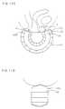
- FIG. 5is a cross-sectional view of the important parts of an air-core type coil apparatus in another embodiment according to the present invention.
- FIG. 6is a perspective view showing a support of the coil shown in FIG. 5.
- FIG. 7is a cross-sectional view and a plan view showing the typical shape of the air-core type coil according to the present invention.
- FIG. 8is a cross-sectional view of the important parts of the coil apparatus having a magnetic core installed at the air-core part of the air-core type coil of FIG. 1.
- FIG. 9is a cross-sectional view of the important parts of a coil having with one magnetic core in an embodiment according to the preset invention.
- FIG. 10is a perspective view showing part of a support of the coil shown in FIG. 9.
- FIGS. 11show a coil fitting type coil apparatus in another embodiment according to the preset invention.
- FIG. 11Ais a cross-sectional view of the apparatus with one coil and
- FIG. 11Bis a cross-sectional view of the apparatus with two coils.
- FIG. 11Cis a cross-sectional view of a coil which is a modified version of the coil of FIG. 11A or FIG. 11B.
- FIG. 11Dis a front view of the coil shown in FIG. 11C.
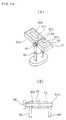
- FIG. 12is a perspective view of a support in another embodiment according to the present invention.
- FIG. 13is a cross-sectional view showing the important parts of the rotatable plate type coil apparatus.
- FIGS. 14show the coil apparatus of FIG. 13.
- FIG. 14Ais a perspective view of the apparatus and
- FIG. 14Bis a cross-sectional view showing part of the apparatus.
- FIG. 3denotes a urinary incontinence treatment apparatus.
- the apparatuscomprises a feeder system 2 in the back of a chair serving as a support of the apparatus, and a coil 10 provided on a seat 1a.
- the coilconsists of three layers formed by rectangularly coiling a rectangular conductor 11 having an insulating material coated film three times along a patient's fitting target region while an air core part 11a is formed at the center. These three layers are connected to one another in parallel and also connected to the feeder system 2.
- the upper surfaceis formed to be curved in a concave manner in the longitudinal direction such that a front coil part 10a which is in front of the air core part 11a is fitted along a region of a urethra opening 3 and a rear coil part 10b is fitted along a region of an anus 4.
- the coilhas a longitudinal width of about 200 mm and a lateral width slightly smaller than the standard gap between joints of both femoral regions to about 100 mm, and the air-core part has a longitudinal width of about 80 mm, a lateral width of about 10 mm and a radius of curvature of about 100 mm.
- the coil 10has respective layers connected to one another and is embedded into the seat part 1a serving as a cushion while the coil 10 remains slightly protruding therefrom such that the coil 10 is securely and closely attached to the fitting target region.
- the central portion of the coil 10 in the lateral directionis preferably protuberant in a corrugated manner to ensure closely fitting the coil to the target region. It is possible to protrude the coil 10 higher with smaller width in stead of the corrugate shape.
- FIG. 4Ashows a circuit arrangement of the feeder system 2.
- the feeder system 2consists of a DC power supply 15 capable of adjusting voltage in a range between 100 V to 2 kV, a capacitor C1 of about 300 ⁇ F to be charged by the DC power supply, a thyristor 16 for applying the charging voltage to the coil 10 through a protective resistor R1, a thyristor 16a for absorbing reverse voltage in a switch-off state and a switching control circuit 17 for on-controlling, that is, ignition-controlling these thyristors through a transformer 16b.
- the repeated frequency of the switching control circuit 17can be adjusted in a range between 1 Hz and 100 Hz.
- the winding structure of the coil 10, the voltage of the DC power supply 15 and the capacity of the capacitor C1allow entire current pulses of about 100 ⁇ s of the coil 10 to generate flux of a flux density of a peak value of about 0.01 to 3 teslas at a maximum of about 3000 A by adjusting voltage.
- a single pulse but also double pulses of about 100 ⁇ s as stated abovecan be employed so as not to give pain to the patient as a result of making a pulse wider.
- various pulse stimulus modescan be selected such as a plurality of continuous pulses, bipolar double pulses shown in the lower part of FIG. 4B.
- the pulse widthis not limited to 100 ⁇ s, but can be set to about 1 ⁇ s to 2 ms depending on the state and symptom of the stimulus target region as in the case of the conventional electrical stimulus treatment.
- the patientsits down on the seat part 1a with his or her clothes on.
- the front coil part 10aslightly protruding at its central portion is fitted to the urethra opening 3 and the rear coil part 10b is fitted to a region of the anus 4.
- the pelvic floor muscle B1 and the pudendal nerves B2are effectively stimulated without unnecessary gaps provided while avoiding stimulating regions such as a urinary bladder 6, a womb 7, an ovary, testicles and the like which are irrelevant to the treatment. Since the hip region is supported at the seat part 1a, the patient feels it comfortable to sit down on the seat part 1a and does not feel tired. Normally, it is enough to apply electric current to such an extent that no forced cooling is required. If needed, however, it may be set to a maximum of about 200 W on condition of cooling the coil.
- FIGS. 5 and 6show a small size coil apparatus of, again, air core type.
- a coil 20is formed to be a closed shape having a longitudinal width of 30 mm and a lateral width of 20 mm according to a plan view.
- the coil 20also consists of conductors 21 insulated from each other on both ends facing each other.
- the air-core part of the coil 20is fitted into a head part 22a of a coil holding member 22 made of synthetic resin.
- Upper surfaces of the conductors 21 and the heat part 22aare molded to have convex surfaces corresponding to the urethra 3 and its surrounding surface regions.
- the coil holding member 22is slightly protruded from a seat part 23 of bicycle saddle shape installed on the tip end portion of a stand 24 such that the upper surface of the coil 20 can be securely and closely attached to the surface regions around the urethra opening 3.
- the pudendal nerves B2are mainly stimulated, which is effective against urge incontinence.
- FIG. 7shows a typical shape of coils including the above-stated coil according to the present invention.
- the longitudinal width L1 of the outer dimensionis 30 to 300 mm and the lateral width W1 is 20 to 120 mm.
- the longitudinal width L2 of the air core partis 20 to 160 mm and the lateral width W2 thereof is 10 to 40 mm.
- the radius of curvature R on the upper surface of the coilis 90 to 150 mm.
- a female patient of large buildhas a longitudinal width L1 of about 300 mm from an upper face region in front of the urethra opening to a rear face region in the back of the anus, and has a lateral width W1 of a maximum of about 120 mm corresponding to the gap between joints of the both femoral regions.
- the eddy currentcan be generated and the shape or inner dimension is specified by a width of a conductor with respect to its outer dimension.
- the upper surfaceis not necessarily completely arc shaped. It can precisely correspond to the shape of the fitting target region and, in some cases, may be slightly curved in the lateral direction.
- the curved shape of the coilcan be provided by molding the surface of the conductor, or by coiling a plurality of conductors along curved surfaces.
- the shape of the coilis not limited to rectangular. It may be circular, ellipsoidal and the like depending on the stimulus target region.
- FIG. 8shows a coil apparatus wherein a magnetic core 29, such as a ferrite core, having good frequency characteristics and low loss is fitted into the air-core part 11a of the coil 10 shown in FIG. 1.
- a magnetic core 29such as a ferrite core
- the pudendal nerves B2are mainly stimulated in a concentrated manner while the flux hardly arrives at the pelvic floor muscle B1. This is especially effective in the treatment for urge incontinence and it can greatly prevent regions irrelevant to the treatment from being stimulated.
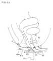
- FIG. 9shows a magnetic core fitting type coil apparatus for fitting a magnetic core to a patient.
- a front end face 35a serving as one magnetic pole of a U-shaped magnetic core 35 around which a coil 30 is woundis located at a slightly upper position than a rear end face 35 b serving as the other magnetic pole thereof and upper surfaces thereof are formed to be concave -curved such that the front end face 35a is fitted to a front face region of the female patient's urethra opening 3 and the rear end face 35b is fitted to a rear face region of the patient's clitoris.
- the magnetic core 35is fitted into a concave portion 37a of a holding member 37 made of synthetic resin and having an upper surface slightly concave-curved. As shown in FIG.
- the holding member 37is installed on the seat part 1a such that the end faces 35a and 35b are slightly protruded from the above-mentioned seat part 1a, and the lower end portion of the coil 30 is exposed to be air-cooled.
- the arch -like fluxcan be generated between the end faces 35a and 35b in a convergent manner to thereby stimulate both the pelvic floor muscle B1 and the pudendal nerves B2. Since the flux can be generated in an effectively convergent manner, power consumption can be greatly reduced.
- FIG. 11Ashows a coil apparatus of, again, magnetic core fitting type.
- a front end face 45a of a U-shaped magnetic core 45 around which a coil 40 is wound,is located at a slightly upper position than a rear end face 45b and upper surfaces thereof are formed to be concave-curved such that the front end face 45a is fitted to a region of the female patient's urethra opening 3 and the rear end face 45b is fitted to a region of a clitoris 5.
- the portion between the end faces 45a and 45bis molded and the surfaces thereof are formed on corresponding curved surface, respectively.
- the magnetic core 45is embedded into a seat part 42 of a chair or stand having a central portion in the longitudinal direction curved to be of corresponding concave shape.
- the end faces 45a and 45b serving as magnetic polesare fitted to come in close contact with a fitting target region. Since the distance between the end faces 45a and 45b is short, the flux does hardly reach the pelvic floor muscle B1 and mainly stimulates the pudendal nerves B2.
- the coil 40includes two coil parts 40a and 40b.
- the coil parts 40a and 40bare wound in the vicinity of the end faces 45a and 45b of the U-shaped magnetic core 45 positioned in the vicinity of the female patient's urethra opening 3 and the clitoris 5, respectively and current is supplied to the coil parts 40a and 40b, respectively such that the flux of the coil parts 40a and 40b flows through the magnetic core 45 in the same direction.
- the coil 40consists of a conductor 46 coiled once to be U-shaped.
- the coil 40comprises a front coil part 40c surrounding vicinity of the urethra opening 3 by forming an air-core part 48 and a rear coil part 40d surrounding the vicinity of the anus 4 by forming an air-core part 48.
- the central portion of the conductor of these coil partsare protuberant in the lateral direction as shown in Fig. 11D. It is possible to install a common U-shaped magnetic core at the air-core part 48 of the conductor 46. Alternatively, the coil 40 can be continuously wound by one conductive line.
- FIG. 12shows a stand type coil support.
- a pipe 51 of the supportslidably supports a rod having a coil 50 with an air core or a magnetic core installed on a tip end portion thereof.
- the position of the coil 50can be locked to a position slidably adjusted by a thumbscrew 52.
- the supportenables the coil 50 to be fitted to a patient who remain standing while adjusting the position of the coil 50 as required.
- FIGS. 13 and 14show a rotation type coil apparatus.
- Complementary-shape protrusion parts 62 and 62a on inner end portions of a pair of rotating plates 61 and 61a into which coils 60 and 60a are embedded, respectively,are rotatably supported by a rotation axis 64 of a stand 65.
- a thumbscrew 66is engaged with the rotation axis 64 and the rotating operation allows a flange part 64a on the opposite end of the rotation axis 64 to be secured to the stand 65 and the adjusted position to be locked.
- the stand 65is provided with a stopper 66 for supporting the rotating plates 61 and 61a in the horizontal direction.
- the lateral widths of the rotating plates 61 and 61aare set in accordance with the gap between the joints of both femoral regions to, for example, 100 mm.
- the coils 60 and 60aare wound around surfaces of the corresponding rotating plates 61 and 61a such that air core parts are formed at central portions, respectively.
- the coil upper surface portion 60b which is in the rear of the air-core part of the coil 60 on the front side rotating plate 61 and the coil upper surface part 60c which is in front of the air core part of the coil 60a of the rear side rotating plate 61aare positioned such that the coil upper surface part 60b is fitted to a region of a female patient's urethra opening 3 and the coil upper surface part 60c is fitted to a region of the patient's clitoris 5.
- the coils 60 and 60aare connected such that they are supplied with current flowing opposite directions.
- the rotation positionis adjusted in accordance with the patient's form and the coil upper surface part 60b is fitted to the urethra opening 3 and the coil upper surface part 60c is fitted to the clitoris 5, thereby stimulating mainly the pudendal nerves B2. It is noted here that if the coil upper surface part 60c is deformed to be positioned in a rear face region of the clitoris 5, a flux generation region becomes wider and the pelvic floor muscle can be simultaneously stimulated.
- the rotating plates 61 and 61aare installed on the tip end portion of the stand as shown in FIG. 12 and to provide a coil apparatus capable of treating a patient while the patient remains standing.
- the lateral widths of the rotating plates 61 and 61aare set to be slightly smaller than that of the standard gap between the joints of femoral regions.
- the rotating plates 61 and 61aare friction -engaged with the rotation axis and held at appropriate adjusted positions so that the structure of the side of the thumbscrew and the like may not be a hindrance to the apparatus.
Landscapes
- Health & Medical Sciences (AREA)
- Engineering & Computer Science (AREA)
- Biomedical Technology (AREA)
- Nuclear Medicine, Radiotherapy & Molecular Imaging (AREA)
- Radiology & Medical Imaging (AREA)
- Life Sciences & Earth Sciences (AREA)
- Animal Behavior & Ethology (AREA)
- General Health & Medical Sciences (AREA)
- Public Health (AREA)
- Veterinary Medicine (AREA)
- Neurology (AREA)
- Magnetic Treatment Devices (AREA)
Abstract
Description
Claims (16)
- A treatment coil apparatus for magnetically treating apatient for urinary incontinence by applying pulsecurrent and thereby generating flux for generatingeddy current to stimulate a physiological body, saidapparatus comprising:a coil (10) having at least an upper surface curved ina convex manner in a longitudinal direction such thatthe coil (10) is fitted to at least part of an areafrom the region of the urethra to the region of theanus, said coil (10) wound around the area: and asupport (1a) for supporting the coil (10) at aposition to be fitted to the patient.
- A treatment coil apparatus according to Claim 1,wherein the longitudinal dimension of the coil (10) is30 to 300 mm and the lateral width of the coil is 20to 120 mm in plan view.
- A treatment coil apparatus according to Claim 1,wherein the longitudinal dimension of the coil (20) isabout 30 mm and the lateral width of the coil is 20 to30 mm in plan view so as to fit the coil to a regionin the vicinity of the urethra opening.
- A treatment coil apparatus according to Claim 1,wherein the longitudinal dimension of the coil (10) is200 to 300 mm and the lateral width of the coil is 50to 120 mm in plan view so as to fit the coil to aregion from the vicinity of the urethra opening to theregion of the anus.
- A treatment coil apparatus according to any one of theClaims 1 to 4, wherein a magnetic core (29, 35) isprovided in an air-core part (11a, 22a) formed at acentral portion around which the coil (10, 20) iswound.
- A treatment coil apparatus according to any one of theClaims 1 to 5, wherein the coil (10, 20) is fitted toa seat part (1a, 23) of the support to sit thepatient, the coil (10, 20) protruding from an uppersurface of the seat part (1a, 23) .
- A treatment coil apparatus according to any one of theClaims 1 to 6, wherein the coil (40) is protuberant ata central portion in a lateral direction.
- A treatment coil apparatus according to any one of theClaims 1 to 7, wherein the support is a chair (1) puton a floor.
- A treatment coil apparatus according to any one of theClaims 1 to 7, wherein the support is a stand (51) puton a floor.
- A treatment coil apparatus according to Claim 1,wherein the coil consists of a front coil part (40c)surrounding the urethra opening with an air core part(48) and a rear coil part (40d) surrounding thevicinity of the anus with an air core part (48a) .
- A treatment coil apparatus according to Claim 10,wherein a common U-shaped magnetic core is provided inthe air core part (48) of the front coil part (40c)and the air core part (48) of the rear coil part(40d) .
- A treatment coil apparatus for magnetically treating apatient for urinary incontinence by applying pulsecurrent and thereby generating flux for generatingeddy current to stimulate a physiological body, saidapparatus comprising:a coil (30) wound around a magnetic core (35); anda support (1a) for supporting said magnetic core (30)at a position to be fitted to the patient, whereinsaid magnetic core is formed such that a pair of endfaces (35a, 35b) spaced from each other for formingmagnetic poles of the magnetic core (35) are fitted toat least part of a region from a front region of theurethra opening to a rear region of the anus.
- A treatment coil apparatus according to Claim 12,wherein the magnetic core (45) is formed such that thefront end face (45a) is fitted to the region in thevicinity of the urethra opening and the rear end face(45b) is fitted to the clitoris region, and said frontend face (45a) is located slightly elevated withrespect to said rear end face (45b).
- A treatment coil apparatus according to Claim 12,wherein the magnetic core (45) is formed such that thefront end face (45a) is fitted to a front face regionof the urethra opening and the rear end face (45b) isfitted to a rear face region of the clitoris, and saidfront end face (45a) is located slightly elevated withrespect to said rear end face (45b) .
- A treatment coil apparatus according to Claim 12, 13or 14, wherein the magnetic core is fitted to a seat part (32) supported by the support (1a) to sit thepatient such that the end faces (35a, 35b) protrudefrom the upper surface of the seat part.
- A treatment coil apparatus for magnetically treating apatient for urinary incontinence by applying pulsecurrent and thereby generating flux for generatingeddy current to stimulate a physiological body, saidapparatus comprising:a pair of front and rear pivotal plates (61, 61a)having inner end portions adjacent to each other androtatably supported at an end portion of a support(65) such that positions of the pivotal plates areadjustable; anda pair of front and rear coils (60, 60a) wound aroundsurfaces of the front and rear pivotal plates (61,61a), respectively, andwherein an upper surface part (60c) of said rear coil(60a) and an upper surface part (60b) of said frontcoil (60) are positioned to fit to at least regionsfrom a front face region of the urethra opening to theanus region at rotating adjusted positions, and saidpair of front and rear coils (60, 60a) are suppliedwith current flowing in directions opposite to eachother.
Applications Claiming Priority (3)
| Application Number | Priority Date | Filing Date | Title |
|---|---|---|---|
| JP35679496 | 1996-12-27 | ||
| JP35679496 | 1996-12-27 | ||
| JP356794/96 | 1996-12-27 |
Publications (3)
| Publication Number | Publication Date |
|---|---|
| EP0850665A2true EP0850665A2 (en) | 1998-07-01 |
| EP0850665A3 EP0850665A3 (en) | 1999-09-01 |
| EP0850665B1 EP0850665B1 (en) | 2004-03-03 |
Family
ID=18450807
Family Applications (1)
| Application Number | Title | Priority Date | Filing Date |
|---|---|---|---|
| EP97122810AExpired - LifetimeEP0850665B1 (en) | 1996-12-27 | 1997-12-23 | Magnetic stimulus type urinary incontinence treatment coil apparatus |
Country Status (3)
| Country | Link |
|---|---|
| US (1) | US6179769B1 (en) |
| EP (1) | EP0850665B1 (en) |
| DE (1) | DE69727902T2 (en) |
Cited By (10)
| Publication number | Priority date | Publication date | Assignee | Title |
|---|---|---|---|---|
| WO2000007665A1 (en)* | 1998-08-03 | 2000-02-17 | Amei Technologies, Inc. | Pemf treatment for osteoporosis and tissue growth stimulation |
| EP0960632A3 (en)* | 1998-05-27 | 2000-08-02 | Nihon Kohden Corporation | Urinary incontinence treatment instrument |
| US6132362A (en)* | 1996-11-01 | 2000-10-17 | Amei Technologies, Inc. | Pulsed electromagnetic field (PEMF) stimulation therapy system with bi-phasic coil |
| US6261221B1 (en) | 1996-11-01 | 2001-07-17 | Amei Technologies Inc. | Flexible coil pulsed electromagnetic field (PEMF) stimulation therapy system |
| EP1120131A3 (en)* | 2000-01-27 | 2001-10-10 | Nihon Kohden Corporation | Electromagnetic coil apparatus for urinary incontinence treatment |
| EP1092451A3 (en)* | 1999-09-30 | 2002-12-11 | Nihon Kohden Corporation | Air-cooling system for a urinary incontinence device |
| WO2010067180A3 (en)* | 2008-12-09 | 2010-08-05 | Pro.Vita S.R.L. | Magnetotherapy apparatus |
| WO2011089472A1 (en)* | 2010-01-19 | 2011-07-28 | Sergey Vladimirovich Pletnev | Portable apparatus for local combined electromagnetic irradiation |
| WO2017055471A1 (en)* | 2015-10-02 | 2017-04-06 | Pontemed Ag | Magnetic stimulation device |
| WO2018051279A1 (en)* | 2016-09-15 | 2018-03-22 | Amel Medical Division S.R.L. | Support structure for the human body for magnetotherapy and sitting including the structure |
Families Citing this family (64)
| Publication number | Priority date | Publication date | Assignee | Title |
|---|---|---|---|---|
| US6436029B1 (en)* | 1995-11-13 | 2002-08-20 | Theodore V. Benderev | External vibratory exercising device for pelvic muscles |
| US6500110B1 (en)* | 1996-08-15 | 2002-12-31 | Neotonus, Inc. | Magnetic nerve stimulation seat device |
| CA2317410A1 (en) | 1998-01-14 | 1999-07-22 | Surx, Inc. | Ribbed electrodes and methods for their use |
| US20020097125A1 (en)* | 2000-06-05 | 2002-07-25 | Kent Davey | Method for optimizing transcranial magnetic stimulation cores and magnetic cores produced thereby |
| KR100497500B1 (en)* | 2002-04-24 | 2005-07-01 | (주) 엠큐브테크놀로지 | A stimulation coil using magnetic mirror and use thereof |
| US7153256B2 (en)* | 2003-03-07 | 2006-12-26 | Neuronetics, Inc. | Reducing discomfort caused by electrical stimulation |
| US8118722B2 (en) | 2003-03-07 | 2012-02-21 | Neuronetics, Inc. | Reducing discomfort caused by electrical stimulation |
| US7601115B2 (en)* | 2004-05-24 | 2009-10-13 | Neuronetics, Inc. | Seizure therapy method and apparatus |
| US7857746B2 (en)* | 2004-10-29 | 2010-12-28 | Nueronetics, Inc. | System and method to reduce discomfort using nerve stimulation |
| DE202004019194U1 (en)* | 2004-12-06 | 2006-04-13 | Storz Medical Ag | Pelvictrainer |
| US7396326B2 (en)* | 2005-05-17 | 2008-07-08 | Neuronetics, Inc. | Ferrofluidic cooling and acoustical noise reduction in magnetic stimulators |
| US7824324B2 (en)* | 2005-07-27 | 2010-11-02 | Neuronetics, Inc. | Magnetic core for medical procedures |
| DE102007006901B4 (en)* | 2007-02-13 | 2011-02-24 | Med.Sse-System Gmbh | Device for the treatment of stool and urinary incontinence by stimulation |
| US8128549B2 (en)* | 2007-02-20 | 2012-03-06 | Neuronetics, Inc. | Capacitor failure detection |
| US7744523B2 (en)* | 2007-06-07 | 2010-06-29 | Emory University | Drive circuit for magnetic stimulation |
| KR101037599B1 (en) | 2008-04-15 | 2011-05-27 | 강선학 | Jade inserts to activate female genital organs and their surrounding tissues |
| DE102012013534B3 (en) | 2012-07-05 | 2013-09-19 | Tobias Sokolowski | Apparatus for repetitive nerve stimulation for the degradation of adipose tissue by means of inductive magnetic fields |
| US9149634B2 (en)* | 2012-12-03 | 2015-10-06 | Alpha Medic Co., Ltd. | Device for strengthening pelvic floor muscles and method for controlling the same |
| US9591925B2 (en)* | 2013-06-21 | 2017-03-14 | Ambreen S Qureshi | Seating cushion for treating pelvic pressure, pain and discomfort |
| US9919161B2 (en) | 2015-07-01 | 2018-03-20 | Btl Holdings Limited | Method of neural structure stimulation by magnetic field |
| US9636519B2 (en) | 2015-07-01 | 2017-05-02 | Btl Holdings Limited | Magnetic stimulation methods and devices for therapeutic treatments |
| US10124187B2 (en) | 2015-04-28 | 2018-11-13 | Btl Holdings Limited | Combination of radiofrequency and magnetic treatment methods |
| US11491342B2 (en) | 2015-07-01 | 2022-11-08 | Btl Medical Solutions A.S. | Magnetic stimulation methods and devices for therapeutic treatments |
| US10549109B2 (en) | 2015-07-01 | 2020-02-04 | Btl Medical Technologies S.R.O. | Aesthetic method of biological structure treatment by magnetic field |
| US20180001107A1 (en) | 2016-07-01 | 2018-01-04 | Btl Holdings Limited | Aesthetic method of biological structure treatment by magnetic field |
| US11266850B2 (en) | 2015-07-01 | 2022-03-08 | Btl Healthcare Technologies A.S. | High power time varying magnetic field therapy |
| US10478634B2 (en) | 2015-07-01 | 2019-11-19 | Btl Medical Technologies S.R.O. | Aesthetic method of biological structure treatment by magnetic field |
| US10821295B1 (en) | 2015-07-01 | 2020-11-03 | Btl Medical Technologies S.R.O. | Aesthetic method of biological structure treatment by magnetic field |
| US10695575B1 (en) | 2016-05-10 | 2020-06-30 | Btl Medical Technologies S.R.O. | Aesthetic method of biological structure treatment by magnetic field |
| US10709894B2 (en) | 2015-07-01 | 2020-07-14 | Btl Medical Technologies S.R.O. | Aesthetic method of biological structure treatment by magnetic field |
| US10549110B1 (en) | 2015-07-01 | 2020-02-04 | Btl Medical Technologies S.R.O. | Aesthetic method of biological structure treatment by magnetic field |
| US10695576B2 (en) | 2015-07-01 | 2020-06-30 | Btl Medical Technologies S.R.O. | Aesthetic method of biological structure treatment by magnetic field |
| US9974519B1 (en) | 2015-07-01 | 2018-05-22 | Btl Holdings Limited | Aesthetic method of biologoical structure treatment by magnetic field |
| US10245439B1 (en) | 2015-07-01 | 2019-04-02 | Medical Technologies Cz A.S. | Aesthetic method of biological structure treatment by magnetic field |
| US10478633B2 (en) | 2015-07-01 | 2019-11-19 | Btl Medical Technologies S.R.O. | Aesthetic method of biological structure treatment by magnetic field |
| US9937358B2 (en) | 2015-07-01 | 2018-04-10 | Btl Holdings Limited | Aesthetic methods of biological structure treatment by magnetic field |
| US10471269B1 (en) | 2015-07-01 | 2019-11-12 | Btl Medical Technologies S.R.O. | Aesthetic method of biological structure treatment by magnetic field |
| US10569094B2 (en) | 2015-07-01 | 2020-02-25 | Btl Medical Technologies S.R.O. | Aesthetic method of biological structure treatment by magnetic field |
| US10493293B2 (en) | 2015-07-01 | 2019-12-03 | Btl Medical Technologies S.R.O. | Aesthetic method of biological structure treatment by magnetic field |
| US11253717B2 (en) | 2015-10-29 | 2022-02-22 | Btl Healthcare Technologies A.S. | Aesthetic method of biological structure treatment by magnetic field |
| US11464993B2 (en) | 2016-05-03 | 2022-10-11 | Btl Healthcare Technologies A.S. | Device including RF source of energy and vacuum system |
| US11247039B2 (en) | 2016-05-03 | 2022-02-15 | Btl Healthcare Technologies A.S. | Device including RF source of energy and vacuum system |
| US11534619B2 (en) | 2016-05-10 | 2022-12-27 | Btl Medical Solutions A.S. | Aesthetic method of biological structure treatment by magnetic field |
| US10583287B2 (en) | 2016-05-23 | 2020-03-10 | Btl Medical Technologies S.R.O. | Systems and methods for tissue treatment |
| US10556122B1 (en) | 2016-07-01 | 2020-02-11 | Btl Medical Technologies S.R.O. | Aesthetic method of biological structure treatment by magnetic field |
| US11141219B1 (en) | 2016-08-16 | 2021-10-12 | BTL Healthcare Technologies, a.s. | Self-operating belt |
| US10039929B1 (en) | 2017-04-04 | 2018-08-07 | BLT Holdings Limited | Method and device for pelvic floor tissue treatment |
| US11896823B2 (en) | 2017-04-04 | 2024-02-13 | Btl Healthcare Technologies A.S. | Method and device for pelvic floor tissue treatment |
| USD913384S1 (en)* | 2017-10-23 | 2021-03-16 | Greenhouse-Team Ag | Pelvic exercise apparatus |
| GB201719104D0 (en)* | 2017-11-17 | 2018-01-03 | Hofmeir Magnetics Ltd | Pulsed electromagnetic field therapy device |
| US11666775B2 (en)* | 2018-03-29 | 2023-06-06 | Minnesota Medical Physics Llc | Method and apparatus for treatment of benign prostatic hyperplasia (BPH) |
| US12156689B2 (en) | 2019-04-11 | 2024-12-03 | Btl Medical Solutions A.S. | Methods and devices for aesthetic treatment of biological structures by radiofrequency and magnetic energy |
| ES2926904T3 (en) | 2019-04-11 | 2022-10-31 | Btl Medical Solutions A S | Device for the aesthetic treatment of biological structures using radiofrequency and magnetic energy |
| US11878167B2 (en) | 2020-05-04 | 2024-01-23 | Btl Healthcare Technologies A.S. | Device and method for unattended treatment of a patient |
| WO2021224678A1 (en) | 2020-05-04 | 2021-11-11 | Btl Medical Technologies S.R.O. | Device and method for unattended treatment of a patient |
| WO2022019695A1 (en)* | 2020-07-23 | 2022-01-27 | 대양의료기(주) | Apparatus for treating urinary incontinence using magnetic field |
| WO2022019696A1 (en)* | 2020-07-23 | 2022-01-27 | 대양의료기(주) | Apparatus for operating urinary incontinence treatment device using magnetic fields, and method therefor |
| US12133812B2 (en) | 2020-09-18 | 2024-11-05 | Suzanne Mary O'Neill | Female urinary incontinence management system |
| KR102506170B1 (en)* | 2020-09-24 | 2023-03-06 | 주식회사 리메드 | Magnetic field application device |
| DE102021111627A1 (en) | 2021-05-05 | 2022-11-10 | Prof. Dr. Fischer AG | Device for magnetic field stimulation of a user's body tissue |
| EP4415812A1 (en) | 2021-10-13 | 2024-08-21 | BTL Medical Solutions a.s. | Devices for aesthetic treatment of biological structures by radiofrequency and magnetic energy |
| US11896816B2 (en) | 2021-11-03 | 2024-02-13 | Btl Healthcare Technologies A.S. | Device and method for unattended treatment of a patient |
| US11583380B1 (en) | 2022-06-16 | 2023-02-21 | Magnetic Five LLC | Male continence device |
| WO2024258812A1 (en)* | 2023-06-13 | 2024-12-19 | Sonostics, Inc. | Apparatus, system and method using magnetic nerve modulation for treatment of reduced cardiac output in the human and methods related thereto |
Family Cites Families (9)
| Publication number | Priority date | Publication date | Assignee | Title |
|---|---|---|---|---|
| DE3721864A1 (en) | 1987-07-02 | 1989-01-12 | Merk Electronic Gmbh | High-reactance transformer (high-leakage-reactance transformer) |
| US5061234A (en)* | 1989-09-25 | 1991-10-29 | Corteks, Inc. | Magnetic neural stimulator for neurophysiology |
| DE3937793A1 (en)* | 1989-11-14 | 1991-05-16 | Datron Electronic Gmbh | Inductive stimulation appts. for diagnostics or therapy - switches precharged capacitor to stimulation coil for rapid discharge via thyristor |
| EP0501048A1 (en)* | 1991-02-25 | 1992-09-02 | Lti-Imd Usa, Inc. | Shielded electromagnetic transducer |
| US5344384A (en)* | 1992-12-11 | 1994-09-06 | Electromagnetic Bracing Systems, Inc. | Magnetotherapy apparatus |
| DE9300499U1 (en)* | 1993-01-21 | 1993-03-25 | Ralf Schrank Magnetfeldtechnik, 7770 Überlingen | Seating furniture for use in magnetic field therapy |
| GB9402545D0 (en)* | 1994-02-10 | 1994-04-06 | Magstim Co Ltd | Magnetic stimulators |
| AU2209195A (en)* | 1994-04-12 | 1995-10-30 | Australasian Medical Technology (Nz) Limited | Orthotic devices incorporating pulsed electromagnetic field therapy |
| US5725471A (en)* | 1994-11-28 | 1998-03-10 | Neotonus, Inc. | Magnetic nerve stimulator for exciting peripheral nerves |
- 1997
- 1997-12-23EPEP97122810Apatent/EP0850665B1/ennot_activeExpired - Lifetime
- 1997-12-23DEDE69727902Tpatent/DE69727902T2/ennot_activeExpired - Lifetime
- 1997-12-23USUS08/996,541patent/US6179769B1/ennot_activeExpired - Lifetime
Cited By (15)
| Publication number | Priority date | Publication date | Assignee | Title |
|---|---|---|---|---|
| US6261221B1 (en) | 1996-11-01 | 2001-07-17 | Amei Technologies Inc. | Flexible coil pulsed electromagnetic field (PEMF) stimulation therapy system |
| US6132362A (en)* | 1996-11-01 | 2000-10-17 | Amei Technologies, Inc. | Pulsed electromagnetic field (PEMF) stimulation therapy system with bi-phasic coil |
| EP0960632A3 (en)* | 1998-05-27 | 2000-08-02 | Nihon Kohden Corporation | Urinary incontinence treatment instrument |
| US6223750B1 (en) | 1998-05-27 | 2001-05-01 | Nihon Kohden Corporation | Urinary incontinence treatment instrument |
| US6418345B1 (en) | 1998-08-03 | 2002-07-09 | Amei Technologies Inc. | PEMF stimulator for treating osteoporosis and stimulating tissue growth |
| WO2000007665A1 (en)* | 1998-08-03 | 2000-02-17 | Amei Technologies, Inc. | Pemf treatment for osteoporosis and tissue growth stimulation |
| US6839595B2 (en)* | 1998-08-03 | 2005-01-04 | Amei Technologies Inc. | PEMF stimulator for treating osteoporosis and stimulating tissue growth |
| EP1092451A3 (en)* | 1999-09-30 | 2002-12-11 | Nihon Kohden Corporation | Air-cooling system for a urinary incontinence device |
| US6527694B1 (en) | 1999-09-30 | 2003-03-04 | Nihon Kohden Corporation | Air-cooling device for coil for urinary incontinence treatment |
| EP1120131A3 (en)* | 2000-01-27 | 2001-10-10 | Nihon Kohden Corporation | Electromagnetic coil apparatus for urinary incontinence treatment |
| WO2010067180A3 (en)* | 2008-12-09 | 2010-08-05 | Pro.Vita S.R.L. | Magnetotherapy apparatus |
| WO2011089472A1 (en)* | 2010-01-19 | 2011-07-28 | Sergey Vladimirovich Pletnev | Portable apparatus for local combined electromagnetic irradiation |
| CN102905759B (en)* | 2010-01-19 | 2015-09-02 | 谢尔盖·弗拉基米罗维奇·普列特尼奥夫 | Portable instrument for locally integrating electromagnetic irradiation |
| WO2017055471A1 (en)* | 2015-10-02 | 2017-04-06 | Pontemed Ag | Magnetic stimulation device |
| WO2018051279A1 (en)* | 2016-09-15 | 2018-03-22 | Amel Medical Division S.R.L. | Support structure for the human body for magnetotherapy and sitting including the structure |
Also Published As
| Publication number | Publication date |
|---|---|
| DE69727902T2 (en) | 2005-03-03 |
| DE69727902D1 (en) | 2004-04-08 |
| EP0850665B1 (en) | 2004-03-03 |
| EP0850665A3 (en) | 1999-09-01 |
| US6179769B1 (en) | 2001-01-30 |
Similar Documents
| Publication | Publication Date | Title |
|---|---|---|
| EP0850665B1 (en) | Magnetic stimulus type urinary incontinence treatment coil apparatus | |
| US20010011152A1 (en) | Coil apparatus for urinary incontinence treatment | |
| US5984854A (en) | Method for treating urinary incontinence and an apparatus therefor | |
| US6223750B1 (en) | Urinary incontinence treatment instrument | |
| AU700482B2 (en) | Magnetic nerve stimulator for exciting peripheral nerves | |
| US6500110B1 (en) | Magnetic nerve stimulation seat device | |
| AU758938B2 (en) | Magnetic nerve stimulator for exciting peripheral nerves | |
| EP1145738B1 (en) | Magnetic stimulation device with litz wire coil | |
| US6527694B1 (en) | Air-cooling device for coil for urinary incontinence treatment | |
| WO2003090863A1 (en) | A stimulation coil using magnetic mirror and use thereof | |
| JPH09276418A (en) | Urinary incontinence treatment device | |
| KR100484618B1 (en) | Apparatus for stimulating nerves | |
| USRE41463E1 (en) | Apparatus for stimulating living tissue | |
| EP3628369B1 (en) | Magnetic field generating-apparatus for biostimulation | |
| JPH10234870A (en) | Magnetic stimulation type incontinence treatment coil device | |
| JP3979013B2 (en) | Coil device for urinary incontinence treatment | |
| JPH1119223A (en) | Urinary incontinence treatment device | |
| KR200345468Y1 (en) | Electromagnetic medical treatment | |
| CN119280685A (en) | Mode-adjustable eye magnetic stimulator and eye care method | |
| MXPA00006350A (en) | Magnetic nerve stimulator for exciting peripheral nerves | |
| JP2001309988A (en) | Magnetic therapeutic instrument | |
| Ishikawa et al. | Eddy current density for non-invasive treatment system for urinary incontinence using Functional Continuous Magnetic Stimulator (FCMS) | |
| JP2005137384A (en) | Potential therapy apparatus and induction current control method | |
| MXPA97003910A (en) | Magnetic stimulator for nerve to excitate peripheral nervous | |
| HK1019207B (en) | Magnetic nerve stimulator for exciting peripheral nerves |
Legal Events
| Date | Code | Title | Description |
|---|---|---|---|
| PUAI | Public reference made under article 153(3) epc to a published international application that has entered the european phase | Free format text:ORIGINAL CODE: 0009012 | |
| AK | Designated contracting states | Kind code of ref document:A2 Designated state(s):DE DK GB | |
| AX | Request for extension of the european patent | Free format text:AL;LT;LV;MK;RO;SI | |
| PUAL | Search report despatched | Free format text:ORIGINAL CODE: 0009013 | |
| AK | Designated contracting states | Kind code of ref document:A3 Designated state(s):AT BE CH DE DK ES FI FR GB GR IE IT LI LU MC NL PT SE | |
| AX | Request for extension of the european patent | Free format text:AL;LT;LV;MK;RO;SI | |
| 17P | Request for examination filed | Effective date:20000223 | |
| AKX | Designation fees paid | Free format text:DE DK GB | |
| GRAH | Despatch of communication of intention to grant a patent | Free format text:ORIGINAL CODE: EPIDOS IGRA | |
| GRAS | Grant fee paid | Free format text:ORIGINAL CODE: EPIDOSNIGR3 | |
| GRAA | (expected) grant | Free format text:ORIGINAL CODE: 0009210 | |
| AK | Designated contracting states | Kind code of ref document:B1 Designated state(s):DE DK GB | |
| REG | Reference to a national code | Ref country code:GB Ref legal event code:FG4D | |
| REF | Corresponds to: | Ref document number:69727902 Country of ref document:DE Date of ref document:20040408 Kind code of ref document:P | |
| PG25 | Lapsed in a contracting state [announced via postgrant information from national office to epo] | Ref country code:DK Free format text:LAPSE BECAUSE OF FAILURE TO SUBMIT A TRANSLATION OF THE DESCRIPTION OR TO PAY THE FEE WITHIN THE PRESCRIBED TIME-LIMIT Effective date:20040603 | |
| PLBE | No opposition filed within time limit | Free format text:ORIGINAL CODE: 0009261 | |
| STAA | Information on the status of an ep patent application or granted ep patent | Free format text:STATUS: NO OPPOSITION FILED WITHIN TIME LIMIT | |
| 26N | No opposition filed | Effective date:20041206 | |
| PGFP | Annual fee paid to national office [announced via postgrant information from national office to epo] | Ref country code:GB Payment date:20131230 Year of fee payment:17 | |
| PGFP | Annual fee paid to national office [announced via postgrant information from national office to epo] | Ref country code:DE Payment date:20140227 Year of fee payment:17 | |
| REG | Reference to a national code | Ref country code:DE Ref legal event code:R119 Ref document number:69727902 Country of ref document:DE | |
| GBPC | Gb: european patent ceased through non-payment of renewal fee | Effective date:20141223 | |
| PG25 | Lapsed in a contracting state [announced via postgrant information from national office to epo] | Ref country code:DE Free format text:LAPSE BECAUSE OF NON-PAYMENT OF DUE FEES Effective date:20150701 Ref country code:GB Free format text:LAPSE BECAUSE OF NON-PAYMENT OF DUE FEES Effective date:20141223 |