EP0850077B1 - Pressure infusion apparatus in combination with a flow regulating valve - Google Patents
Pressure infusion apparatus in combination with a flow regulating valveDownload PDFInfo
- Publication number
- EP0850077B1 EP0850077B1EP96927231AEP96927231AEP0850077B1EP 0850077 B1EP0850077 B1EP 0850077B1EP 96927231 AEP96927231 AEP 96927231AEP 96927231 AEP96927231 AEP 96927231AEP 0850077 B1EP0850077 B1EP 0850077B1
- Authority
- EP
- European Patent Office
- Prior art keywords
- pressure
- infusion
- chamber
- bag
- infusion bag
- Prior art date
- Legal status (The legal status is an assumption and is not a legal conclusion. Google has not performed a legal analysis and makes no representation as to the accuracy of the status listed.)
- Expired - Lifetime
Links
- 238000001802infusionMethods0.000titleclaimsabstractdescription88
- 230000001105regulatory effectEffects0.000titleclaimsabstractdescription26
- 239000012528membraneSubstances0.000claimsabstractdescription16
- 239000007788liquidSubstances0.000claimsdescription25
- 238000004891communicationMethods0.000claimsdescription4
- 210000002445nippleAnatomy0.000claimsdescription3
- 239000012530fluidSubstances0.000claimsdescription2
- 239000003978infusion fluidSubstances0.000abstractdescription3
- 230000008878couplingEffects0.000description9
- 238000010168coupling processMethods0.000description9
- 238000005859coupling reactionMethods0.000description9
- 239000000463materialSubstances0.000description5
- 238000010276constructionMethods0.000description4
- 229920003023plasticPolymers0.000description4
- 239000003814drugSubstances0.000description3
- 239000004033plasticSubstances0.000description3
- 230000001154acute effectEffects0.000description2
- 230000033228biological regulationEffects0.000description2
- 210000001035gastrointestinal tractAnatomy0.000description2
- 238000001990intravenous administrationMethods0.000description2
- 238000000034methodMethods0.000description2
- 230000035764nutritionEffects0.000description2
- 235000016709nutritionNutrition0.000description2
- 210000003462veinAnatomy0.000description2
- XLYOFNOQVPJJNP-UHFFFAOYSA-NwaterSubstancesOXLYOFNOQVPJJNP-UHFFFAOYSA-N0.000description2
- 210000004204blood vesselAnatomy0.000description1
- 230000007423decreaseEffects0.000description1
- 238000013461designMethods0.000description1
- 238000010586diagramMethods0.000description1
- 229940079593drugDrugs0.000description1
- 239000004744fabricSubstances0.000description1
- 239000011521glassSubstances0.000description1
- 239000007924injectionSubstances0.000description1
- 238000002347injectionMethods0.000description1
- 230000007774longtermEffects0.000description1
- 230000002093peripheral effectEffects0.000description1
- 239000002574poisonSubstances0.000description1
- 231100000614poisonToxicity0.000description1
- 230000002980postoperative effectEffects0.000description1
- 230000003389potentiating effectEffects0.000description1
- 238000003825pressingMethods0.000description1
- 230000002265preventionEffects0.000description1
- 230000035939shockEffects0.000description1
- 239000000243solutionSubstances0.000description1
- 238000007920subcutaneous administrationMethods0.000description1
- 238000012360testing methodMethods0.000description1
- 230000001225therapeutic effectEffects0.000description1
Images


Classifications
- A—HUMAN NECESSITIES
- A61—MEDICAL OR VETERINARY SCIENCE; HYGIENE
- A61M—DEVICES FOR INTRODUCING MEDIA INTO, OR ONTO, THE BODY; DEVICES FOR TRANSDUCING BODY MEDIA OR FOR TAKING MEDIA FROM THE BODY; DEVICES FOR PRODUCING OR ENDING SLEEP OR STUPOR
- A61M5/00—Devices for bringing media into the body in a subcutaneous, intra-vascular or intramuscular way; Accessories therefor, e.g. filling or cleaning devices, arm-rests
- A61M5/14—Infusion devices, e.g. infusing by gravity; Blood infusion; Accessories therefor
- A61M5/142—Pressure infusion, e.g. using pumps
- A61M5/145—Pressure infusion, e.g. using pumps using pressurised reservoirs, e.g. pressurised by means of pistons
- A61M5/148—Pressure infusion, e.g. using pumps using pressurised reservoirs, e.g. pressurised by means of pistons flexible, e.g. independent bags
- A61M5/1483—Pressure infusion, e.g. using pumps using pressurised reservoirs, e.g. pressurised by means of pistons flexible, e.g. independent bags using flexible bags externally pressurised by fluid pressure
Definitions
- the present inventionconcerns a pressure infusion apparatus comprising an infusion chamber adapted to accept at least one infusion bag, the infusion bag being adapted to contain liquid and being in fluid communication with an infusion tube, and a pressure apparatus adapted for exerting a pressure on the infusion bag so as to supply liquid from the infusion bag to the infusion tube, wherein the pressure apparatus comprises pressure supply chamber, and a pressure expressing means in pneumatic communication with the pressure supply chamber and connected thereto via a pressure reduction valve, which pressure expressing means expels a pressure upon the said infusion bag, the pressure reduction valve being adapted to significantly reduce a pressure in the pressure expressing means relative to the maximum loading pressure in the pressure supply chamber, the pressure expressing means further comprising an unstretchable, air tight, flexible membrane) being the active pressure expressing object of the pressure expressing means and exerting a pressure upon an infusion bag present in the infusion chamber, and wherein the membrane applies pressure from the pressure supply chamber directly to the at least one infusion bag,
- the most usual method of applying the liquid intravenouslyis to hang up the bag on a support about a meter over the patient and to bring the liquid from the bag to the needle in the vein, usually placed in the arm, via a plastic tube.
- the flowis regulated by a flow reduction apparatus in the tube and the amount of liquid is controlled by observation of the drop rate in a drop chamber higher up in the tube.
- the Swedish publication text nr 467 951shows an infusion apparatus consisting of an infusion bag and on it a normally permanently fixed infusion tube including an opening tool and a flow indicator, a clip and a stop valve which prevents return flow to the bag. In use the infusion apparatus is placed under the patient to provide pressure.
- the Swedish publication text nr 448 822shows a portable apparatus including a spring for providing liquid at constant pressure for medical or other similar applications.
- the springexerts a constant force moment whereby sticking due to possible twisting of the sliding piece on which the spring exerts its force is eliminated.
- WO 89/11303shows an apparatus including a spring which exerts an axial force on a vessel containing a liquid in order to squeeze out the liquid.
- German Publication text 2053995shows a system including a lower and an upper pressure plate which can be provided with a rubber band around the plates to press them together whereby pressure is applied to an infusion bag placed between the plates so that the liquid is squeezed out of the bag.
- German patent application DE-A-2,246,054which shows the features of the preamble of claim 1 relates to an apparatus for subcutaneous distribution of intravenous liquids comprising a means for expelling pressure on an compressible bottle provided with an outlet, which bottle comprises a gaseous and a liquid content.
- the gaseous contentis provided to expel a pressure upon the liquid content to distribute the same.
- the bottleis provided with pressure reducing valve to regulate the pressure on the gaseous content.
- the purpose of the present inventionis to achieve an infusion apparatus
- the apparatuscan also be used for continuous application of nutrition to the digestive tract through a thin tube.
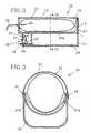
- the pressure infusion apparatus 10 shown in fig. 1-5includes a housing 11 consisting of a chamber 13 with a top 12 for an infusion bag 21 and below it a vessel 14 which contains part of a pressure apparatus 18. At one end of the housing 11 there is an instrument panel including further parts belonging to the pressure apparatus 18, namely a flow meter 15, a pressure indicator, for instance a pressure gauge 16, a close off valve 17 and a connection nipple 19, which parts will be described in greater detail below. At the same end the top 12 has a slit 20 through which the output tube 24 of the infusion bag is inserted.
- the top 12preferably made of a transparent plastic material with a semicircular cross section, is attached to the lower part of the housing on hinges 31 (fig. 3) on one long side and can be made fast with locks 22, for example eccentric locks, on the other long side.
- Fig. 2 and 3show schematically a cross section through the exemplification shown in fig. 1.
- a pressure source 27which consists of a membrane 27a or similar thing which divides the chamber 13 into an infusion chamber and a pressure chamber 27b.
- the membrane 27ais made of a supple, flexible air tight material, for example a cloth, which essentially cannot be stretched but which is so large that in the passive state it lies against the bottom of the chamber and in the stretched state it presses against the inside of the top.
- the pressure chamber 27b of the pressure source 27is thus formed by the said membrane 27a and the bottom and side walls of the pressure chamber.
- the membrane (27a)is attached to the inside of the chamber (13) at about half its height, the membrane being so dimensioned that in the passive state it lies against the bottom of the pressure chamber (27b) and in the pressurised, inflated state it presses against the top or cap (12) of the chamber (13).
- the function and use of the pressure apparatus 18will now be described with reference to fig. 6. It contains a pressure storage chamber 25 in the form of a pressure vessel 14 for compressed air, which storage chamber 25 can be attached to a pump (not shown) via a nipple 19 with a stop valve 34, which pump fills the storage chamber with compressed air, for example at a pressure of 6.5 kg/cm 2 .
- the pressure gauge 16shows the pressure in the pressure storage chamber 25. In use, that is, when an infusion bag 21 has been placed in the infusion chamber, the two way valve 17 is opened and compressed air flows to the pressure reduction valve 26 of conventional type.
- the pressureis reduced, for example to 0.15 kg/cm 2 , and the pressure chamber 27b is pressurised, whereby the flow meter 15 indicates how much air has been let into the chamber, that being an approximate measure of the amount of infusion liquid that has flowed out of the infusion bag 21.
- the valve 17is readjusted so that the interior of the pressure chamber 27b communicates with the atmosphere and air enters it.
- the infusion apparatusis designed to be mobile it can also be equipped with a pump, for example a hand or foot pump to pump air into the pressure storage chamber. It can also be detachable for quick exchange with a pressurised vessel.
- a pumpfor example a hand or foot pump to pump air into the pressure storage chamber. It can also be detachable for quick exchange with a pressurised vessel.
- the tube 24 attached to the bag 21is equipped in a known way with a needle 33 for perforation of a membrane in the output channel of the bag while the other end of the tube is equipped with a coupling 37, for example in the form of a luer lock coupling 41, as is shown in fig. 7 and 8.
- a flow regulating valve 28is coupled, which in the exemplification according to fig. 8 has been given a form similar to that of the coupling 37 and which consists of a neck 39 and an inner conical hole 40 to which the luer lock coupling's 37 male coupling 38 having the same conical form is attached.
- the other part of the valveis equipped with a luer lock coupling 41 while the conical piece 35 corresponding to the male coupling 38 has a hole 30, for example with a diameter of 0.2-0.5 mm.
- the holeis made of a part of an infusion needle of desired inner diameter moulded in the flow regulating valve 28.
- Each flow regulating valve 28thus has an exactly determined hole diameter, on the drawing fig. 8 indicated by a d, and a given hole length 1 for each type of valve.
- Several flow regulating valves 28can be arranged in series after each other, possibly with different hole lengths 1 from 3 to 15 mm, but with the same hole diameter, if a greater reduction is desired.
- the flow regulating valve (28)is a constant reduction valve with a flow hole (30) with an exact length (1) to diameter (d) ratio, preferably of the order of 5-10 mm length and 0.2-0.5 mm inner diameter, and whereby preferably there is several reducing valves (28) with the same flow hole diameter connected in series.
- each flow regulating valve (28)is separately attachable to a common output via a direction regulating valve (43).
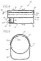
- Fig. 4 and 5show the infusion apparatus illustrated in fig. 2 and 3 but with the membrane 27a of the pressure source 27 inflated and with the infusion bag 21 in the compressed, almost empty state.
- valves 28can be parallel coupled in an infusion unit 36 as is shown in fig. 9.
- the unit 36includes a stop-cock 43 with an input flow opening and three output flow openings each of which is separately attachable to the input flow opening which in turn is attachable to the coupling 37 of the output tube 24.
- One or more flow regulating valves 28are coupled to each output opening via appropriate filters.
- Valve combination I (mm) d (mm)1 5 0.3 2 10 0.3 3 5 0.5 4 10 0.5
- valve combination 1For valve combination 1 an infusion bag lasts for 2 1/2 hours.
- valve combination 3an infusion bag lasts for about 20 minutes.
- valve combination 4an infusion bag lasts for about 50 minutes.
- valve combination (3 + 4)an infusion bag lasts for about 1 hour.
- the flow regulating valvesare thus calibrated to give a certain amount of liquid per unit time. They can be coupled in series according to fig. 8 to increase the number of possibilities and they can be marked with clear information. For increased safety colour markings can be used.
- the flow regulating valves' free endsare coupled to a needle 32 in a vein.
- the whole apparatuscan then be placed beside the patent on the bed, on a table or something else near the patient. It requires no elevation above the patent and it can also be carried by the patient on a strap or in a bag. No drop indicator is needed. No one is needed to hold the bag when there has been an accident or a catastrophe. It is easy to use for example in an ambulance. Because there is no air in the system air embolii are eliminated and the risk of incorrect dosage is minimal. In most cases the precision is sufficient for dosage of medicines.
- the pressure infusion apparatuscan be placed in the conventional manner about 1 1/2 meters above the patient thus ensuring a flow due to gravitational force.
- the chamber 13 in the housing 11can be cylindrical with only one opening in the forward end of the housing through which the infusion bag 21 is inserted into the apparatus 10 (the top 13 thus being eliminated).
Landscapes
- Health & Medical Sciences (AREA)
- Hematology (AREA)
- Animal Behavior & Ethology (AREA)
- Vascular Medicine (AREA)
- Engineering & Computer Science (AREA)
- Anesthesiology (AREA)
- Biomedical Technology (AREA)
- Fluid Mechanics (AREA)
- Heart & Thoracic Surgery (AREA)
- Life Sciences & Earth Sciences (AREA)
- Physics & Mathematics (AREA)
- General Health & Medical Sciences (AREA)
- Public Health (AREA)
- Veterinary Medicine (AREA)
- Infusion, Injection, And Reservoir Apparatuses (AREA)
- Closures For Containers (AREA)
- Containers And Packaging Bodies Having A Special Means To Remove Contents (AREA)
Abstract
Description
- which does not depend on an external source of energy,
- for which no one need hold the liquid containing bag in acute situations,
- for which there is no drop support,
- in which the amount of liquid to be given the patient per unit time is easily adjusted,
- in which the liquid flow is constant during the infusion making checks andadjustments unnecessary,
- in which air is absent from the system, thus eliminating air bubbles,
- which is simple and robust and requires few instructions making it especiallyappropriate in connection with large catastrophes when many people must be treated atthe same time,
- the price of which is kept low through use of disposable material.
| Valve combination | I (mm) | d (mm) |
| 1 | 5 | 0.3 |
| 2 | 10 | 0.3 |
| 3 | 5 | 0.5 |
| 4 | 10 | 0.5 |
| Valve combination | flow (ml/hr) |
| 1 | 400 |
| 2 | 200 |
| 1 + 2 (in series) | 120 |
| 3 | 3200 |
| 4 | 1200 |
| 3 + 4 (in series) | 900 |
Claims (7)
- A pressure infusion apparatus (10) in combination with at least one infusion bag (21) and a flow regulating valve (28) comprising an infusion chamber (13) adapted toaccept said at least one infusion bag (21), the infusion bag (21) being arranged to containliquid and being in fluid communication with an infusion tube (24), and a pressureapparatus (18) adapted for exerting a pressure on the infusion bag (21) so as to supplyliquid from the infusion bag (21) to the infusion tube (24), wherein the pressureapparatus (18) comprises a pressure supply chamber (25) and a pressure expressingmeans (27) in pneumatic communication with the pressure supply chamber (25) andconnected thereto via a pressure reduction valve (26), which pressure expressingmeans (27) expels a pressure upon the said infusion bag (21), the pressure reductionvalve (26) being adapted to significantly reduce a pressure in the pressure expressingmeans (27) relative to the maximum loading pressure in the pressure supply chamber(25), the pressure expressing means (27) further comprising an unstretchable, air tight,flexible membrane (27a) being the active pressure expressing object of the pressureexpressing means and exerting a pressure upon the infusion bag present in the infusionchamber, and wherein the membrane applies pressure from the pressure supplychamber directly to the at least one infusion bag,
characterized inthat the infusion bag (21) or an extension from the infusion bag is connected to at leastone subsequent flow regulating valve (28)) in the form of a constant reduction valve with a flow hole (30) with an exact length (ℓ) to diameter (d) ratiogiving an exactly determined flow rate per unit time. - Pressure infusion apparatus according to claim 1,
characterized inthat the pressure storage chamber (25) is suitable to be filled using a separate pump or comprises a pumpintegrated into the pressure apparatus. - Pressure infusion apparatus according to claim 1 or 2,
characterized inthat the pressure storage chamber (25) is equipped with a nipple (19) for attachmentto an external pressure source. - Pressure infusion apparatus according to claim 1,
characterized inthat the membrane (27a) is attached to the inside of the chamber (13) at about half itsheight, the membrane being so dimensioned that in the passive state it lies against thebottom of the pressure chamber (27b) and in the pressurised, inflated state it pressesagainst the top or cap (12) of the chamber (13). - Pressure infusion apparatus according to claim 1,
characterized inthat the length(I) to diameter (d) ratio is preferably of the order of 5-10 mm length and 0.2-0.5 mminner diameter. - Pressure infusion apparatus according to claim 5,
characterized inthat there are several reducing valves (28) with the same flow hole diameter coupled inseries. - Pressure infusion apparatus according to claim 5,
characterized inthat there are several flow regulating valves (28) having different flow hole diameters (d)and/or lengths (I) parallel coupled to an infusion unit (36) and
each flow regulating valve (28) is separately attachable to a common output via adirection regulating valve (43).
Applications Claiming Priority (3)
| Application Number | Priority Date | Filing Date | Title |
|---|---|---|---|
| SE9502789ASE9502789D0 (en) | 1995-08-09 | 1995-08-09 | Pressure infusion apparatus |
| SE9502789 | 1995-08-09 | ||
| PCT/SE1996/001007WO1997005915A1 (en) | 1995-08-09 | 1996-08-09 | Pressure infusion apparatus |
Publications (2)
| Publication Number | Publication Date |
|---|---|
| EP0850077A1 EP0850077A1 (en) | 1998-07-01 |
| EP0850077B1true EP0850077B1 (en) | 2005-04-06 |
Family
ID=20399144
Family Applications (1)
| Application Number | Title | Priority Date | Filing Date |
|---|---|---|---|
| EP96927231AExpired - LifetimeEP0850077B1 (en) | 1995-08-09 | 1996-08-09 | Pressure infusion apparatus in combination with a flow regulating valve |
Country Status (12)
| Country | Link |
|---|---|
| US (1) | US6406458B1 (en) |
| EP (1) | EP0850077B1 (en) |
| JP (1) | JPH11510415A (en) |
| AT (1) | ATE292486T1 (en) |
| AU (1) | AU700259B2 (en) |
| CA (1) | CA2228760C (en) |
| DE (1) | DE69634570T2 (en) |
| ES (1) | ES2240998T3 (en) |
| NO (1) | NO319594B1 (en) |
| RU (1) | RU2177806C2 (en) |
| SE (1) | SE9502789D0 (en) |
| WO (1) | WO1997005915A1 (en) |
Cited By (1)
| Publication number | Priority date | Publication date | Assignee | Title |
|---|---|---|---|---|
| WO2024261272A1 (en)* | 2023-06-22 | 2024-12-26 | EasyJector GmbH | Automatic syringe |
Families Citing this family (36)
| Publication number | Priority date | Publication date | Assignee | Title |
|---|---|---|---|---|
| SE8301395L (en)* | 1983-03-15 | 1984-09-16 | Wallac Oy | KELATIZING COMPOUNDS WITH FUNCTIONAL GROUPS WHICH ALLOW COVALENT COUPLING TO BIO-ORGANIC MOLECULES |
| ES2327985T3 (en)* | 1997-11-04 | 2009-11-05 | Smiths Medical Asd, Inc. | INFUSION SYSTEM WITH IMPROVED CONTROL VALVE. |
| DE19907744A1 (en)* | 1999-02-23 | 2000-08-24 | Backes Claus H | Unit for intracorporal injections comprises a space for a bag with the injection medium, and a device allowing the bag to be subjected directly or indirectly to a pressurized fluid |
| SE0000866L (en)* | 2000-03-16 | 2001-09-17 | Peter Unger Med P U Med Konsul | Method and apparatus for the treatment of biological material |
| IL152950A0 (en) | 2002-11-19 | 2003-06-24 | Biometrix Ltd | A fluid administrating manifold |
| EP1624915A1 (en)* | 2003-04-11 | 2006-02-15 | Novo Nordisk A/S | Delivery device |
| US20060069382A1 (en)* | 2003-04-11 | 2006-03-30 | Novo Nordisk A/S | Delivery device |
| AT413649B (en)* | 2003-08-04 | 2006-04-15 | Pro Med Medizinische Produktio | DEVICE FOR DOSED DISPENSING OF A LIQUID |
| DE602004022075D1 (en)* | 2003-10-21 | 2009-08-27 | Novo Nordisk As | RESERVOIR DEVICE WITH INTEGRATED FASTENER |
| CN100586414C (en)* | 2003-10-21 | 2010-02-03 | 诺沃挪第克公司 | Reservoir device with inclined needle |
| EP1755522A1 (en)* | 2004-06-07 | 2007-02-28 | Novo Nordisk A/S | Reservoir with liquidly applied seal |
| US8070668B2 (en)* | 2006-01-20 | 2011-12-06 | L-Vad Technology | Controlled inflation of a pneumatic L-VAD |
| WO2009023797A1 (en)* | 2007-08-14 | 2009-02-19 | Innercool Therapies, Inc. | Methods and systems for inducing therapeutic hypothermia in a pre-hospital, field, or ambulance setting |
| WO2009119519A1 (en)* | 2008-03-24 | 2009-10-01 | オリンパス株式会社 | Medicine administration device |
| US20120164718A1 (en)* | 2008-05-06 | 2012-06-28 | Innovative Micro Technology | Removable/disposable apparatus for MEMS particle sorting device |
| WO2010014673A1 (en)* | 2008-07-29 | 2010-02-04 | Mallinckrodt Inc. | Injection device with expandable drive fluid chamber |
| GB0821492D0 (en)* | 2008-11-25 | 2008-12-31 | Team Holdings Uk Ltd | Integrated auto-injector cartridge system |
| WO2010141458A2 (en) | 2009-06-03 | 2010-12-09 | Biometrix Ltd | Apparatus and method for bedside collection of body fluids and automatic volume level monitoring |
| US9357950B2 (en) | 2009-06-03 | 2016-06-07 | Biometrix Ltd. | Apparatus and method of fluid aspiration |
| US8696630B2 (en)* | 2011-01-28 | 2014-04-15 | Calibra Medical, Inc. | Detachable drug delivery device |
| CN103874519B (en)* | 2011-06-24 | 2016-03-16 | 解救点滴有限公司 | Elasticity infusion pump |
| WO2013123257A1 (en)* | 2012-02-14 | 2013-08-22 | Paul Miller | Pump and monitor for iv pressure bag infusers |
| US9364610B2 (en) | 2012-05-07 | 2016-06-14 | Antares Pharma, Inc. | Injection device with cammed ram assembly |
| CN104043158A (en)* | 2013-03-13 | 2014-09-17 | 解救点滴有限公司 | Rugged Infusion Device |
| WO2016089554A1 (en)* | 2014-12-04 | 2016-06-09 | University Of Florida Research Foundation, Inc. | Devices and methods for minimizing infusion of air into an intravenous fluid line from an intravenous fluid bag by a pressure infusion cuff |
| CN106564704B (en)* | 2016-11-02 | 2019-03-15 | 东华理工大学 | Micro-control sampler bag |
| US11504472B2 (en) | 2017-07-06 | 2022-11-22 | Quasuras, Inc. | Medical pump with flow control |
| DE102017125266B4 (en) | 2017-10-27 | 2025-03-13 | IDTM GmbH | Multi-piston contrast medium injector |
| CN107929871A (en)* | 2018-01-10 | 2018-04-20 | 程基才 | A kind of free style can retention transfusion system without draw point essence control |
| CN110141720B (en)* | 2019-06-21 | 2021-04-27 | 青岛大学附属医院 | An operating room blood transfusion bag heat preservation and pressure device |
| US11717636B2 (en)* | 2019-10-01 | 2023-08-08 | GE Precision Healthcare LLC | Anesthesia vaporizer system having a variable volume reservoir |
| WO2021113538A1 (en) | 2019-12-06 | 2021-06-10 | Quasuras, Inc. | Training cartridge for medical pump systems |
| CN111068173B (en)* | 2020-01-03 | 2022-07-29 | 上海旭润医学科技有限责任公司 | Disposable wearable micro-flow continuous drug delivery system |
| US11817197B2 (en) | 2020-02-07 | 2023-11-14 | Quasuras, Inc. | Medical pump electronic pairing with device |
| JP7439961B2 (en)* | 2021-02-01 | 2024-02-28 | 株式会社村田製作所 | Pressure device |
| DE102024000953A1 (en)* | 2024-03-21 | 2025-09-25 | EasyJector GmbH | Shielded infusion system |
Family Cites Families (11)
| Publication number | Priority date | Publication date | Assignee | Title |
|---|---|---|---|---|
| US3640277A (en)* | 1968-12-09 | 1972-02-08 | Marvin Adelberg | Medical liquid administration device |
| DE2053995A1 (en) | 1970-11-03 | 1972-05-04 | Lang, Volker, Dr.Med., 8045 Ismaning | Pressure infusion system especially suitable for emergencies |
| ZA726230B (en)* | 1971-09-28 | 1973-05-30 | Bestnu Eng Ltd | Intravenous fluids administration apparatus |
| IL50038A0 (en) | 1976-07-14 | 1976-09-30 | Cohen A | A device for pressure-infusion of fluids |
| US4447232A (en) | 1982-05-21 | 1984-05-08 | Repro-Med Systems, Inc. | Spring-operated liquid-dispensing device |
| US4778451A (en)* | 1986-03-04 | 1988-10-18 | Kamen Dean L | Flow control system using boyle's law |
| FR2631551A1 (en) | 1988-05-17 | 1989-11-24 | Soudant Jacques | SYSTEM FOR PERFUSION OF A LIQUID INTO A BLOOD PATH, PARTICULARLY OF A HUMAN BEING |
| SE467951B (en) | 1990-12-13 | 1992-10-12 | Axel Johnson Lab System | Infusion apparatus |
| US5207645A (en)* | 1991-06-25 | 1993-05-04 | Medication Delivery Devices | Infusion pump, treatment fluid bag therefor, and method for the use thereof |
| US5348539A (en)* | 1993-06-29 | 1994-09-20 | Glenn Herskowitz | Infusion pump for use with prepackaged IV bags |
| US5700245A (en)* | 1995-07-13 | 1997-12-23 | Winfield Medical | Apparatus for the generation of gas pressure for controlled fluid delivery |
- 1995
- 1995-08-09SESE9502789Apatent/SE9502789D0/enunknown
- 1996
- 1996-08-09EPEP96927231Apatent/EP0850077B1/ennot_activeExpired - Lifetime
- 1996-08-09ATAT96927231Tpatent/ATE292486T1/ennot_activeIP Right Cessation
- 1996-08-09CACA002228760Apatent/CA2228760C/ennot_activeExpired - Fee Related
- 1996-08-09WOPCT/SE1996/001007patent/WO1997005915A1/enactiveIP Right Grant
- 1996-08-09RURU98104423/14Apatent/RU2177806C2/ennot_activeIP Right Cessation
- 1996-08-09AUAU67121/96Apatent/AU700259B2/ennot_activeCeased
- 1996-08-09ESES96927231Tpatent/ES2240998T3/ennot_activeExpired - Lifetime
- 1996-08-09USUS09/011,444patent/US6406458B1/ennot_activeExpired - Fee Related
- 1996-08-09JPJP9508381Apatent/JPH11510415A/enactivePending
- 1996-08-09DEDE69634570Tpatent/DE69634570T2/ennot_activeExpired - Fee Related
- 1998
- 1998-02-04NONO19980476Apatent/NO319594B1/enunknown
Cited By (1)
| Publication number | Priority date | Publication date | Assignee | Title |
|---|---|---|---|---|
| WO2024261272A1 (en)* | 2023-06-22 | 2024-12-26 | EasyJector GmbH | Automatic syringe |
Also Published As
| Publication number | Publication date |
|---|---|
| DE69634570T2 (en) | 2006-02-16 |
| ATE292486T1 (en) | 2005-04-15 |
| EP0850077A1 (en) | 1998-07-01 |
| DE69634570D1 (en) | 2005-05-12 |
| WO1997005915A1 (en) | 1997-02-20 |
| JPH11510415A (en) | 1999-09-14 |
| US6406458B1 (en) | 2002-06-18 |
| ES2240998T3 (en) | 2005-10-16 |
| NO319594B1 (en) | 2005-08-29 |
| RU2177806C2 (en) | 2002-01-10 |
| CA2228760A1 (en) | 1997-02-20 |
| NO980476L (en) | 1998-02-04 |
| AU6712196A (en) | 1997-03-05 |
| CA2228760C (en) | 2004-08-03 |
| SE9502789D0 (en) | 1995-08-09 |
| AU700259B2 (en) | 1998-12-24 |
| NO980476D0 (en) | 1998-02-04 |
Similar Documents
| Publication | Publication Date | Title |
|---|---|---|
| EP0850077B1 (en) | Pressure infusion apparatus in combination with a flow regulating valve | |
| US5549672A (en) | Method and apparatus for filling mammary prostheses and tissue expanders | |
| US5059182A (en) | Portable infusion device | |
| US5911716A (en) | Platen pump | |
| US4043332A (en) | Constant flow rate liquid medicament administering device | |
| US3469578A (en) | Infusion device for ambulatory patients with flow control means | |
| EP2047876B1 (en) | Self-contained portable apparatus for administration of a drug solution | |
| US4337769A (en) | Pressure infusion module | |
| US3640277A (en) | Medical liquid administration device | |
| US5304153A (en) | Apparatus and system for the self-dosing of a liquid medicine | |
| US4636197A (en) | Intravenous fluid infusion device | |
| US4505701A (en) | Automatic parenteral infusion apparatus | |
| GB2039849A (en) | Liquid metering device | |
| JPH02500816A (en) | Methods and devices for drug administration particularly useful in the field of injections | |
| EP0951307B1 (en) | Drug delivery means | |
| US5298025A (en) | Sequential flow rate infusion rate | |
| US5263935A (en) | Pressurized fluid dispenser | |
| US8313475B2 (en) | Liquid dispenser | |
| US4186740A (en) | Method and apparatus for regulating intravenous flow of a liquid | |
| US4345594A (en) | Closely controllable intravenous injection system | |
| AU2002340621A1 (en) | Liquid dispenser | |
| US7762982B1 (en) | Breast implant fill device | |
| JPS61164564A (en) | Automatic solution injector | |
| JPH02131778A (en) | Discharging method for medicine introduced into body and its dosing method thereby | |
| EP0600754A2 (en) | Constant pharmaceutical infuser |
Legal Events
| Date | Code | Title | Description |
|---|---|---|---|
| PUAI | Public reference made under article 153(3) epc to a published international application that has entered the european phase | Free format text:ORIGINAL CODE: 0009012 | |
| 17P | Request for examination filed | Effective date:19980309 | |
| AK | Designated contracting states | Kind code of ref document:A1 Designated state(s):AT BE CH DE DK ES FI FR GB GR IE IT LI LU MC NL PT SE | |
| RAP1 | Party data changed (applicant data changed or rights of an application transferred) | Owner name:PREMETEC AB | |
| RIN1 | Information on inventor provided before grant (corrected) | Inventor name:TILLANDER, HANS | |
| 17Q | First examination report despatched | Effective date:20010302 | |
| RTI1 | Title (correction) | Free format text:PRESSURE INFUSION APPARATUS IN COMBINATION WITH A FLOW REGULATING VALVE | |
| GRAP | Despatch of communication of intention to grant a patent | Free format text:ORIGINAL CODE: EPIDOSNIGR1 | |
| GRAS | Grant fee paid | Free format text:ORIGINAL CODE: EPIDOSNIGR3 | |
| GRAA | (expected) grant | Free format text:ORIGINAL CODE: 0009210 | |
| AK | Designated contracting states | Kind code of ref document:B1 Designated state(s):AT BE CH DE DK ES FI FR GB GR IE IT LI LU MC NL PT SE | |
| PG25 | Lapsed in a contracting state [announced via postgrant information from national office to epo] | Ref country code:LI Free format text:LAPSE BECAUSE OF FAILURE TO SUBMIT A TRANSLATION OF THE DESCRIPTION OR TO PAY THE FEE WITHIN THE PRESCRIBED TIME-LIMIT Effective date:20050406 Ref country code:CH Free format text:LAPSE BECAUSE OF FAILURE TO SUBMIT A TRANSLATION OF THE DESCRIPTION OR TO PAY THE FEE WITHIN THE PRESCRIBED TIME-LIMIT Effective date:20050406 | |
| REG | Reference to a national code | Ref country code:GB Ref legal event code:FG4D | |
| REG | Reference to a national code | Ref country code:CH Ref legal event code:EP | |
| REG | Reference to a national code | Ref country code:IE Ref legal event code:FG4D | |
| REF | Corresponds to: | Ref document number:69634570 Country of ref document:DE Date of ref document:20050512 Kind code of ref document:P | |
| PG25 | Lapsed in a contracting state [announced via postgrant information from national office to epo] | Ref country code:GR Free format text:LAPSE BECAUSE OF FAILURE TO SUBMIT A TRANSLATION OF THE DESCRIPTION OR TO PAY THE FEE WITHIN THE PRESCRIBED TIME-LIMIT Effective date:20050706 Ref country code:DK Free format text:LAPSE BECAUSE OF FAILURE TO SUBMIT A TRANSLATION OF THE DESCRIPTION OR TO PAY THE FEE WITHIN THE PRESCRIBED TIME-LIMIT Effective date:20050706 | |
| REG | Reference to a national code | Ref country code:SE Ref legal event code:TRGR | |
| PG25 | Lapsed in a contracting state [announced via postgrant information from national office to epo] | Ref country code:LU Free format text:LAPSE BECAUSE OF NON-PAYMENT OF DUE FEES Effective date:20050809 | |
| PG25 | Lapsed in a contracting state [announced via postgrant information from national office to epo] | Ref country code:MC Free format text:LAPSE BECAUSE OF NON-PAYMENT OF DUE FEES Effective date:20050831 | |
| PGFP | Annual fee paid to national office [announced via postgrant information from national office to epo] | Ref country code:ES Payment date:20050831 Year of fee payment:10 | |
| PG25 | Lapsed in a contracting state [announced via postgrant information from national office to epo] | Ref country code:PT Free format text:LAPSE BECAUSE OF FAILURE TO SUBMIT A TRANSLATION OF THE DESCRIPTION OR TO PAY THE FEE WITHIN THE PRESCRIBED TIME-LIMIT Effective date:20050908 | |
| REG | Reference to a national code | Ref country code:CH Ref legal event code:PL | |
| REG | Reference to a national code | Ref country code:ES Ref legal event code:FG2A Ref document number:2240998 Country of ref document:ES Kind code of ref document:T3 | |
| PLBE | No opposition filed within time limit | Free format text:ORIGINAL CODE: 0009261 | |
| STAA | Information on the status of an ep patent application or granted ep patent | Free format text:STATUS: NO OPPOSITION FILED WITHIN TIME LIMIT | |
| ET | Fr: translation filed | ||
| 26N | No opposition filed | Effective date:20060110 | |
| PGFP | Annual fee paid to national office [announced via postgrant information from national office to epo] | Ref country code:NL Payment date:20060731 Year of fee payment:11 | |
| PGFP | Annual fee paid to national office [announced via postgrant information from national office to epo] | Ref country code:IE Payment date:20060801 Year of fee payment:11 Ref country code:BE Payment date:20060801 Year of fee payment:11 | |
| PGFP | Annual fee paid to national office [announced via postgrant information from national office to epo] | Ref country code:AT Payment date:20060803 Year of fee payment:11 | |
| PGFP | Annual fee paid to national office [announced via postgrant information from national office to epo] | Ref country code:FI Payment date:20060804 Year of fee payment:11 | |
| BERE | Be: lapsed | Owner name:*PREMETEC A.B. Effective date:20070831 | |
| PG25 | Lapsed in a contracting state [announced via postgrant information from national office to epo] | Ref country code:NL Free format text:LAPSE BECAUSE OF NON-PAYMENT OF DUE FEES Effective date:20080301 | |
| NLV4 | Nl: lapsed or anulled due to non-payment of the annual fee | Effective date:20080301 | |
| PG25 | Lapsed in a contracting state [announced via postgrant information from national office to epo] | Ref country code:FI Free format text:LAPSE BECAUSE OF NON-PAYMENT OF DUE FEES Effective date:20070809 | |
| PGFP | Annual fee paid to national office [announced via postgrant information from national office to epo] | Ref country code:IT Payment date:20080227 Year of fee payment:12 Ref country code:GB Payment date:20080225 Year of fee payment:12 Ref country code:DE Payment date:20080226 Year of fee payment:12 | |
| REG | Reference to a national code | Ref country code:IE Ref legal event code:MM4A | |
| PG25 | Lapsed in a contracting state [announced via postgrant information from national office to epo] | Ref country code:AT Free format text:LAPSE BECAUSE OF NON-PAYMENT OF DUE FEES Effective date:20070809 | |
| PGFP | Annual fee paid to national office [announced via postgrant information from national office to epo] | Ref country code:FR Payment date:20080226 Year of fee payment:12 | |
| PG25 | Lapsed in a contracting state [announced via postgrant information from national office to epo] | Ref country code:BE Free format text:LAPSE BECAUSE OF NON-PAYMENT OF DUE FEES Effective date:20070831 | |
| PG25 | Lapsed in a contracting state [announced via postgrant information from national office to epo] | Ref country code:IE Free format text:LAPSE BECAUSE OF NON-PAYMENT OF DUE FEES Effective date:20070809 | |
| REG | Reference to a national code | Ref country code:ES Ref legal event code:FD2A Effective date:20070810 | |
| PG25 | Lapsed in a contracting state [announced via postgrant information from national office to epo] | Ref country code:ES Free format text:LAPSE BECAUSE OF NON-PAYMENT OF DUE FEES Effective date:20070810 | |
| GBPC | Gb: european patent ceased through non-payment of renewal fee | Effective date:20080809 | |
| REG | Reference to a national code | Ref country code:FR Ref legal event code:ST Effective date:20090430 | |
| PG25 | Lapsed in a contracting state [announced via postgrant information from national office to epo] | Ref country code:IT Free format text:LAPSE BECAUSE OF NON-PAYMENT OF DUE FEES Effective date:20080809 Ref country code:FR Free format text:LAPSE BECAUSE OF NON-PAYMENT OF DUE FEES Effective date:20080901 Ref country code:DE Free format text:LAPSE BECAUSE OF NON-PAYMENT OF DUE FEES Effective date:20090303 | |
| PG25 | Lapsed in a contracting state [announced via postgrant information from national office to epo] | Ref country code:GB Free format text:LAPSE BECAUSE OF NON-PAYMENT OF DUE FEES Effective date:20080809 | |
| PGFP | Annual fee paid to national office [announced via postgrant information from national office to epo] | Ref country code:SE Payment date:20090821 Year of fee payment:14 | |
| EUG | Se: european patent has lapsed | ||
| PG25 | Lapsed in a contracting state [announced via postgrant information from national office to epo] | Ref country code:SE Free format text:LAPSE BECAUSE OF NON-PAYMENT OF DUE FEES Effective date:20100810 |