EP0850033B1 - Intraurethral bladder control device with retainer apparatus - Google Patents
Intraurethral bladder control device with retainer apparatusDownload PDFInfo
- Publication number
- EP0850033B1 EP0850033B1EP96928224AEP96928224AEP0850033B1EP 0850033 B1EP0850033 B1EP 0850033B1EP 96928224 AEP96928224 AEP 96928224AEP 96928224 AEP96928224 AEP 96928224AEP 0850033 B1EP0850033 B1EP 0850033B1
- Authority
- EP
- European Patent Office
- Prior art keywords
- housing
- bladder
- retainer
- urethra
- control apparatus
- Prior art date
- Legal status (The legal status is an assumption and is not a legal conclusion. Google has not performed a legal analysis and makes no representation as to the accuracy of the status listed.)
- Expired - Lifetime
Links
- 238000007915intraurethral administrationMethods0.000titleabstractdescription8
- 210000003708urethraAnatomy0.000claimsabstractdescription34
- 239000012530fluidSubstances0.000claimsabstractdescription16
- 241001313288LabiaSpecies0.000claimsabstractdescription6
- 239000004606Fillers/ExtendersSubstances0.000claimsdescription9
- 230000000717retained effectEffects0.000description3
- 210000005070sphincterAnatomy0.000description3
- 230000014759maintenance of locationEffects0.000description2
- 230000015572biosynthetic processEffects0.000description1
- 238000013016dampingMethods0.000description1
- 230000010339dilationEffects0.000description1
- 239000003112inhibitorSubstances0.000description1
- 208000014674injuryDiseases0.000description1
- 238000000034methodMethods0.000description1
- 210000003205muscleAnatomy0.000description1
- 230000008733traumaEffects0.000description1
Images


Classifications
- A—HUMAN NECESSITIES
- A61—MEDICAL OR VETERINARY SCIENCE; HYGIENE
- A61F—FILTERS IMPLANTABLE INTO BLOOD VESSELS; PROSTHESES; DEVICES PROVIDING PATENCY TO, OR PREVENTING COLLAPSING OF, TUBULAR STRUCTURES OF THE BODY, e.g. STENTS; ORTHOPAEDIC, NURSING OR CONTRACEPTIVE DEVICES; FOMENTATION; TREATMENT OR PROTECTION OF EYES OR EARS; BANDAGES, DRESSINGS OR ABSORBENT PADS; FIRST-AID KITS
- A61F2/00—Filters implantable into blood vessels; Prostheses, i.e. artificial substitutes or replacements for parts of the body; Appliances for connecting them with the body; Devices providing patency to, or preventing collapsing of, tubular structures of the body, e.g. stents
- A61F2/0004—Closure means for urethra or rectum, i.e. anti-incontinence devices or support slings against pelvic prolapse
- A61F2/0009—Closure means for urethra or rectum, i.e. anti-incontinence devices or support slings against pelvic prolapse placed in or outside the body opening close to the surface of the body
- Y—GENERAL TAGGING OF NEW TECHNOLOGICAL DEVELOPMENTS; GENERAL TAGGING OF CROSS-SECTIONAL TECHNOLOGIES SPANNING OVER SEVERAL SECTIONS OF THE IPC; TECHNICAL SUBJECTS COVERED BY FORMER USPC CROSS-REFERENCE ART COLLECTIONS [XRACs] AND DIGESTS
- Y10—TECHNICAL SUBJECTS COVERED BY FORMER USPC
- Y10S—TECHNICAL SUBJECTS COVERED BY FORMER USPC CROSS-REFERENCE ART COLLECTIONS [XRACs] AND DIGESTS
- Y10S128/00—Surgery
- Y10S128/25—Artificial sphincters and devices for controlling urinary incontinence
Definitions
- the present inventiongenerally relates to the field of medical devices and more particularly to intraurethral bladder control devices, and still more particularly to intraurethral bladder control devices with retaining means.
- bladder control devicesoften referred to as artificial sphincters
- the use of bladder control devicesis wide spread in the field of the present invention.
- the use of such intraurethral valving apparatus and its general knowledge in the field of artcan be evidenced by, for example US-A-4, 553, 533, US-A-4, 679, 546; US-A-4, 969, 474 and US-A-5,123,428.
- the US-A-4,553,533discloses a prosthetic urethral sphincter valve that is placed totally within a patient's urethra.
- the valveincluding a collapsible flexible thin-walled annular bag member secured in a rigid casing with flexible retaining petals at its top end receivable in the patient's bladder.
- An upstanding annular flexible thin-walled diaphragmis provided over an inturned top flange on the casing, the flange having small flow apertures forming damping ports communicating with the flexible bag member.
- the bottom end of the bag memberis engaged with an annular guide urged upwardly by a coiled spring bearing on an inturned bottom flange of the casing.
- a plurality of evenly spaced resilient retaining petal membersare fixedly secured to an outer corner rim of the annular top flange in outwardly and upwardly divergent relationship to the top of the casing and are flatly retentively engageable with the upwardly divergent bottom wall surface of the bladder to hold the sphincter valve assembly in the working position.
- the US-A-3 812 841shows a urethra magnetic valve structure comprising an implantable tubular valve housing to be located in the urethra at its juncture with the bladder.
- the valve housinghas a pair of spaced, inflatable retention collars to be inflated for supporting the valve unit in proper position with a slotted head portion of the housing in the bladder.
- the first re-tainer meansare leaf springs which are compressed during placement of the bladder control device into the urethra. The leaves spring open when the distal end of the bladder control device reaches the opening into the bladder from the urethra.
- distal endshall mean the end of a device or internal lumen which is in-tended to be closest to the bladder, and the term “proximal end” shall mean the end of the device or lumen which is closest to the urethral labia.
- a bladder control apparatuswhich is retained in a patient's urethra by a first retaining means operable within the bladder and by a second retaining means abutting the labia of the urethra.
- Fig. 1discloses a perspective view of the bladder control device 10 of this invention. It can be seen that the device 10 includes an upper or retainer housing 12 and a lower or full control housing 15. The distal end of housing 15 is connected to the proximal end of housing 12 such that an internal lumen within each of housings 12 and 15 (as fully depicted in each of Figs. 2, 3 and 4 of the following drawings) combine to make one continuous fluid flow path through the device 10.
- a first retainer 30is connected to the distal end of housing 12.
- retainer 30is shown as a leaf spring having a plurality of leaves, in this embodiment four leaves 30a to 30d.
- each of the leaves of spring 30is provided with a generally hemispherical deposit 31 which acts as a safety device to prevent the tips of each leaf or spring 30 from damaging the internal wall of the bladder.
- a second retainer(not shown in Fig. 1, but present in each of the following figures of the drawings) is adapted to be connected to the proximal end 17 of housing 15 after device 10 has been placed in the urethra of a patient and retainer 30 has opened in the bladder of the patient.
- a cross-sectional plane view of the assembled apparatus of this inventioncomprising bladder control device 10. It can be seen that a nut 33, having a central lumen, is used to mount spring 30 within the lumen of housing 12. It can be seen that the leaves of spring or upper retainer 30 are in their uncompressed or extended position, as they would be when inside the bladder of a patient. It can also be clearly seen how safety device 31 takes the form of a hemispherical formation at the tip of each of the leaves of leaf spring or retainer 30.
- a valve assemblyfor controlling the flow of fluid through the lumen, the assembly comprising a stopper 16, a biasing means or spring 22, a first mounting ring 18 that defines the inner housing chamber within which stopper moves, and a second spring mounting ring 24.
- the ring 24is mounted within housing 15 and receives the proximal end of the bias means or spring 22.
- Ring 18is mounted for rotational movement within housing 15, and has its distal movement inhibited by a ridge 13 within housing 15.
- Spring 22extends through mounting ring 18 and has its distal end connected to stopper 16, which stopper 16 is slidably mounted for movement within the lumen of housing 15.
- a second or lower retainer 35has a first portion adapted to be connected to the proximal end of housing 15, preferably by a threaded connection.
- Retainer 35also has a second section which is significantly wider than either of housings 12 or 15, and thus it will be wider than the urethra after placement of device 10 within the urethral.
- the second portion or wider portion of retainer 35is adapted to contact the labia.
- FIG. 3the apparatus of Fig. 2 is shown in exploded view.
- nut 33is placed to hold the bladder retaining means or spring 30 within the lumen of housing 12.
- housing 15has its distal end connected to the proximal end of housing 12.
- stopper 16is positioned through the lumen of housing 15 to abut a narrowed inner portion of the lumen of housing 15 and how ring 18 is then slid through the proximal end 17 of the lumen of housing 15 to abut the ridge 13 in the wall of the lumen of housing 15.
- Spring 22then has its upper or distal portion placed through the lumen of housing 15, through ring 18 and into connection with stopper 16.
- Ring 24is then placed to receive the proximal end of bias means or spring 22 and is pushed through the proximal end 17 of housing 15 and connected within the lumen of housing 15. Finally, after placement of the apparatus of Fig. 3 within the urethra of the patient, the second retainer or lower retainer 35 is threaded into position at the proximal end 17 of housing 15.
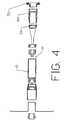
- FIG. 4there is shown another exploded view forming yet another embodiment of the apparatus of this invention. It will be apparent from Fig. 4 that all the parts of this embodiment are the same as the parts of Figs. 2 and 3 with the exception of an extender 40 placed between ring 24 and retaining means 35.
- housing 15is adapted to receive the distal end of extender 40, preferably by threading, and retainer 35 is then connected to the proximal end of extender 40 instead of the proximal end of housing 15.
- the apparatus of Fig. 4shows an embodiment of the apparatus of this invention whereby the length of device 10 can be selectively changed by utilizing any one of a number of different sizes of extender 40.
- FIG. 5there is shown a partial cross-sectional view representative of the urethra and bladder of a patient.
- the bladder control device 10is shown after placement in the urethra of the patient and after whatever placement devices which were used have been removed and the urethra has undilated to closely hold and form to the outer surface of device 10. It can be seen how retainer 30 in the form of a leaf spring has opened within the bladder and how the safety devices on the tips of the leaves of spring 30 provide a safety factor to prevent puncture of the bladder wall by the tips of the leaves.
Landscapes
- Health & Medical Sciences (AREA)
- Urology & Nephrology (AREA)
- Cardiology (AREA)
- Oral & Maxillofacial Surgery (AREA)
- Transplantation (AREA)
- Engineering & Computer Science (AREA)
- Biomedical Technology (AREA)
- Heart & Thoracic Surgery (AREA)
- Vascular Medicine (AREA)
- Life Sciences & Earth Sciences (AREA)
- Animal Behavior & Ethology (AREA)
- General Health & Medical Sciences (AREA)
- Public Health (AREA)
- Veterinary Medicine (AREA)
- Prostheses (AREA)
- Orthopedics, Nursing, And Contraception (AREA)
- Supply Devices, Intensifiers, Converters, And Telemotors (AREA)
- Massaging Devices (AREA)
- Medicines Containing Antibodies Or Antigens For Use As Internal Diagnostic Agents (AREA)
- Thermotherapy And Cooling Therapy Devices (AREA)
- Medicines Containing Material From Animals Or Micro-Organisms (AREA)
- External Artificial Organs (AREA)
Abstract
Description
Claims (7)
- Bladder control apparatus for placement within the urethra of a patient, comprising:characterized in that said first retainer means comprises a leaf spring (30) including a pluralityof spring leaves (30a to 30d) extending out of said housing (12, 15) and that a hemispherical deposit (31)is mounted on the tip of each of said plurality of leaves (30a to 30d) to inhibit damage to the bladderwalls.a housing (12, 15) defining a fluid flow lumen;flow control valve (16, 22) mounted in the lumen for controlling the flow of fluid,first retainer means (30) connected to the bladder end of the lumen, and operablewithin the bladder after placement of the housing (12, 15) in the urethra, for retaining a placedhousing (12, 15) within the urethra, andsecond retainer means (35) connected to the other end of the housing (12, 15) and extendingfrom the urethra, for retaining the placed housing (12, 15) within the urethra,
- The bladder control apparatus of claim 1, wherein the valve comprises:stopper means (16) mounted in said housing flow path;bias means (22) mounted in said housing flow path, and connected to said stoppermeans (16) for normally biasing said stopper means to block said flow path; whereinsaid bias means (22) is responsive to fluid pressure on said stopper means (16) for unblockingsaid flow path.
- The bladder control apparatus of claim 2, including calibration means mounted in saidhousing (12,15) for adjusting the tension said bias means (22) applies on said stopper means(16).
- The bladder control apparatus of claim 1, wherein the housing comprises
a retainer housing (12) including a first lumen, and said retainer housing (12) includingdistal and proximal ends, the first retainer means (30) being connected adjacent said distal endof said retainer housing (12);
a flow control housing (15) including a second lumen, and said control housing (15)including distal and proximal ends, the flow control valve (16, 22) mounted in said secondlumen, the second retainer means (35) being connected adjacent said proximal end of saidcontrol housing (159; and wherein
said distal end of said control housing (15) is connected to said proximal end of saidretainer housing (12) for forming a housing end for aligning said first and second lumens forproviding a continuous fluid flow path. - The bladder control apparatus of claim 4, wherein said second retainer (35) includes afirst section for selective connection to said housing (12, 15) proximal end when said housing(12, 15) is placed within a urethra; and a second section for extending out of and being widerthan the urethra, for contact with the urethral labia.
- The bladder control apparatus of claim 5, further comprising
an extender housing (40) including a third lumen, and said extender housing includingdistal and proximal ends;
means for connecting said extender housing (40) distal end to said control housing (15)proximal end; and
means for connecting said second retainer (35) first section to said extender housing(40) proximal end. - The bladder control apparatus of claim 1, wherein said spring leaves (30 a to 30d) arecompressed during passage of said housing (12) through the urethra and automatically openedwithin the bladder when the bladder end of said housing (12) has reached the bladder.
Applications Claiming Priority (3)
| Application Number | Priority Date | Filing Date | Title |
|---|---|---|---|
| US08/515,920US5701916A (en) | 1995-08-16 | 1995-08-16 | Intraurethral bladder control device with retainer apparatus |
| US515920 | 1995-08-16 | ||
| PCT/US1996/013348WO1997006758A1 (en) | 1995-08-16 | 1996-08-15 | Intraurethral bladder control device with retainer apparatus |
Publications (3)
| Publication Number | Publication Date |
|---|---|
| EP0850033A1 EP0850033A1 (en) | 1998-07-01 |
| EP0850033A4 EP0850033A4 (en) | 1999-10-27 |
| EP0850033B1true EP0850033B1 (en) | 2003-12-03 |
Family
ID=24053327
Family Applications (1)
| Application Number | Title | Priority Date | Filing Date |
|---|---|---|---|
| EP96928224AExpired - LifetimeEP0850033B1 (en) | 1995-08-16 | 1996-08-15 | Intraurethral bladder control device with retainer apparatus |
Country Status (10)
| Country | Link |
|---|---|
| US (3) | US5701916A (en) |
| EP (1) | EP0850033B1 (en) |
| JP (1) | JPH11511989A (en) |
| AT (1) | ATE255388T1 (en) |
| AU (1) | AU702335B2 (en) |
| CA (1) | CA2229533A1 (en) |
| DE (1) | DE69630962T2 (en) |
| ES (1) | ES2211967T3 (en) |
| NO (1) | NO980635D0 (en) |
| WO (1) | WO1997006758A1 (en) |
Families Citing this family (43)
| Publication number | Priority date | Publication date | Assignee | Title |
|---|---|---|---|---|
| US5701916A (en)* | 1995-08-16 | 1997-12-30 | Hk Medical Technologies Incorporated | Intraurethral bladder control device with retainer apparatus |
| US5751606A (en)* | 1996-05-03 | 1998-05-12 | Hk Medical Technologies Incorporated | Automatic valve test apparatus |
| US5782916A (en)* | 1996-08-13 | 1998-07-21 | Galt Laboratories, Inc. | Device for maintaining urinary continence |
| US5964732A (en) | 1997-02-07 | 1999-10-12 | Abbeymoor Medical, Inc. | Urethral apparatus with position indicator and methods of use thereof |
| US6042535A (en)* | 1997-07-17 | 2000-03-28 | Srs Medical Systems, Inc. | Flow-around valve |
| US5971967A (en) | 1997-08-19 | 1999-10-26 | Abbeymoor Medical, Inc. | Urethral device with anchoring system |
| US5996585A (en)* | 1997-08-21 | 1999-12-07 | Hk Medical Technologies Incorporated | Nonsurgical intraurethral bladder control device retainer |
| US5871016A (en)* | 1997-10-08 | 1999-02-16 | Hk Medical Technologies Incorporated | Bladder control device retainer and method |
| US6056687A (en) | 1997-12-04 | 2000-05-02 | American Medical Systems, Inc. | Device for alleviating urinary incontinence |
| US6200261B1 (en) | 1998-03-04 | 2001-03-13 | American Medical Systems, Inc. | Valve and methods for urinary control |
| US6030337A (en)* | 1998-07-30 | 2000-02-29 | American Medical Systems, Inc. | Continence augmentor and methods for urinary control |
| US6093191A (en)* | 1998-10-28 | 2000-07-25 | Srs Medical, Inc. | Flow-around valve with contoured fixation balloon |
| US6213936B1 (en) | 1998-11-20 | 2001-04-10 | Hk Medical Technologies Incorporated | Bladder control device actuator |
| US6183413B1 (en)* | 1998-12-09 | 2001-02-06 | Hk Medical Technologies Incorporated | Valve for bladder control device |
| EP1191902B1 (en)* | 1999-04-30 | 2005-03-09 | HK Medical Technologies Incorporated | Intraurethral device |
| NO993788L (en)* | 1999-08-05 | 2001-02-06 | Knut Ove Kristensen | Urinary valve with electronic opening / closing |
| US6551304B1 (en)* | 1999-12-01 | 2003-04-22 | Abbeymoor Medical, Inc. | Magnetic retrieval device and method of use |
| US6527702B2 (en)* | 2000-02-01 | 2003-03-04 | Abbeymoor Medical, Inc. | Urinary flow control device and method |
| US10327880B2 (en) | 2000-04-14 | 2019-06-25 | Attenuex Technologies, Inc. | Attenuation device for use in an anatomical structure |
| US7141038B2 (en)* | 2000-08-07 | 2006-11-28 | Abbeymoor Medical, Inc. | Endourethral device and method |
| US6719709B2 (en)* | 2000-08-31 | 2004-04-13 | Abbeymoor Medical, Inc. | Diagnostic urethral assembly and method |
| ATE483492T1 (en)* | 2001-01-23 | 2010-10-15 | Abbeymoor Medical Inc | ENDOURETHRAL DEVICE |
| WO2002060357A1 (en)* | 2001-01-29 | 2002-08-08 | Eutech Medical Ab | Valve assembly |
| JP4083683B2 (en)* | 2001-09-07 | 2008-04-30 | マーディル, インコーポレイテッド | Method and apparatus for external heart fixation |
| US6991596B2 (en)* | 2001-10-18 | 2006-01-31 | Abbeymoor Medical, Inc. | Endourethral device and method |
| US20060195006A1 (en)* | 2005-02-28 | 2006-08-31 | Daurelle Bernard Adrien S | Intraurethral incontinence device and methods |
| WO2007072469A2 (en) | 2005-12-23 | 2007-06-28 | Vysera Biomedical Limited | A medical device suitable for treating reflux from a stomach to an oesophagus |
| US20070208217A1 (en) | 2006-03-03 | 2007-09-06 | Acorn Cardiovascular, Inc. | Self-adjusting attachment structure for a cardiac support device |
| US20070276342A1 (en)* | 2006-03-28 | 2007-11-29 | Bryant Lin | Devices and related methods for treating incontinence |
| US8092363B2 (en)* | 2007-09-05 | 2012-01-10 | Mardil, Inc. | Heart band with fillable chambers to modify heart valve function |
| AU2009261580B2 (en) | 2008-06-20 | 2016-01-28 | Coloplast A/S | Esophageal valve |
| WO2010068467A1 (en) | 2008-11-25 | 2010-06-17 | Attenuex Technologies, Inc. | Implant with high vapor pressure medium |
| CA3063081C (en) | 2009-12-18 | 2022-04-12 | Coloplast A/S | A urological device |
| US20120238802A1 (en)* | 2011-03-15 | 2012-09-20 | Joseph Allen Knight | Short-term device for the treatment of urinary incontinence in women |
| US8992410B2 (en) | 2010-11-03 | 2015-03-31 | Vysera Biomedical Limited | Urological device |
| CA3100305A1 (en) | 2011-12-19 | 2013-06-27 | Coloplast A/S | A luminal prosthesis and a gastrointestinal implant device |
| ITPI20120025A1 (en) | 2012-03-17 | 2013-09-18 | Giuliani Giuseppe | STRUCTURE OF ENETURETHRAL URETHRO-VESICAL BORDER |
| US8894563B2 (en) | 2012-08-10 | 2014-11-25 | Attenuex Technologies, Inc. | Methods and systems for performing a medical procedure |
| AU2013328871B2 (en) | 2012-10-12 | 2018-08-16 | Diaxamed, Llc | Cardiac treatment system and method |
| USD717954S1 (en) | 2013-10-14 | 2014-11-18 | Mardil, Inc. | Heart treatment device |
| WO2016005824A1 (en)* | 2014-07-09 | 2016-01-14 | Ovitigalage Saliya Ovitigala | Intra-urethral device for the treatment of urinary incontinence of females |
| WO2020163625A1 (en) | 2019-02-07 | 2020-08-13 | Solace Therapeutics, Inc. | Pressure attenuation device |
| US11865270B2 (en) | 2020-01-16 | 2024-01-09 | Starling Medical, Inc. | Bodily fluid management system |
Family Cites Families (15)
| Publication number | Priority date | Publication date | Assignee | Title |
|---|---|---|---|---|
| US3628530A (en)* | 1969-03-24 | 1971-12-21 | Jerome Schwartz | Intrauterine device for contraception |
| US3812841A (en)* | 1972-08-21 | 1974-05-28 | L Isaacson | Urethra magnetic valve structure |
| US4246896A (en)* | 1978-10-30 | 1981-01-27 | Dynatech Corp. | Intracervical cuff (ICC) for contraception and prevention of venereal disease and applicator therefor |
| US4553533A (en)* | 1983-11-08 | 1985-11-19 | Leighton Stephen B | Intra-urethral prosthetic sphincter valve |
| NL8403174A (en)* | 1984-10-17 | 1986-05-16 | Franciscus Jacobus Maria De Vr | IMPLANTABLE SEALING DEVICE. |
| US4969474A (en)* | 1988-10-11 | 1990-11-13 | Schwarz Gerald R | Incontinence bladder control method and apparatus |
| US5123428A (en)* | 1988-10-11 | 1992-06-23 | Schwarz Gerald R | Laparoscopically implanting bladder control apparatus |
| US5234409A (en)* | 1989-07-07 | 1993-08-10 | Cabot Technology Corporation | Female incontinence control device and method |
| US5041092A (en)* | 1989-08-29 | 1991-08-20 | Medical Engineering Corporation | Urethral indwelling catheter with magnetically controlled drainage valve and method |
| US5140999A (en)* | 1991-09-30 | 1992-08-25 | Primed International Corp. | Urinary incontinence valve device |
| US5512032A (en)* | 1993-12-23 | 1996-04-30 | Hk Medical Technologies, Inc. | Nonsurgical intraurethral bladder control device |
| US5762599A (en)* | 1994-05-02 | 1998-06-09 | Influence Medical Technologies, Ltd. | Magnetically-coupled implantable medical devices |
| US5624374A (en)* | 1994-11-03 | 1997-04-29 | Von Iderstein; Irwin F. | Involuntary urine control apparatus, system and method |
| IL111953A (en)* | 1994-12-12 | 2012-04-30 | Medical Influence Technologies Ltd | Device for catheter fixation |
| US5701916A (en)* | 1995-08-16 | 1997-12-30 | Hk Medical Technologies Incorporated | Intraurethral bladder control device with retainer apparatus |
- 1995
- 1995-08-16USUS08/515,920patent/US5701916A/ennot_activeExpired - Fee Related
- 1996
- 1996-08-15ESES96928224Tpatent/ES2211967T3/ennot_activeExpired - Lifetime
- 1996-08-15ATAT96928224Tpatent/ATE255388T1/ennot_activeIP Right Cessation
- 1996-08-15AUAU67779/96Apatent/AU702335B2/ennot_activeCeased
- 1996-08-15EPEP96928224Apatent/EP0850033B1/ennot_activeExpired - Lifetime
- 1996-08-15WOPCT/US1996/013348patent/WO1997006758A1/enactiveIP Right Grant
- 1996-08-15JPJP9509525Apatent/JPH11511989A/ennot_activeCeased
- 1996-08-15DEDE69630962Tpatent/DE69630962T2/ennot_activeExpired - Fee Related
- 1996-08-15CACA002229533Apatent/CA2229533A1/ennot_activeAbandoned
- 1997
- 1997-04-08USUS08/833,649patent/US5887592A/ennot_activeExpired - Fee Related
- 1998
- 1998-02-16NONO980635Apatent/NO980635D0/ennot_activeApplication Discontinuation
- 1999
- 1999-02-09USUS09/246,466patent/US6193646B1/ennot_activeExpired - Fee Related
Also Published As
| Publication number | Publication date |
|---|---|
| NO980635L (en) | 1998-02-16 |
| US5701916A (en) | 1997-12-30 |
| CA2229533A1 (en) | 1997-02-27 |
| NO980635D0 (en) | 1998-02-16 |
| EP0850033A4 (en) | 1999-10-27 |
| DE69630962T2 (en) | 2004-10-28 |
| WO1997006758A1 (en) | 1997-02-27 |
| US6193646B1 (en) | 2001-02-27 |
| DE69630962D1 (en) | 2004-01-15 |
| US5887592A (en) | 1999-03-30 |
| EP0850033A1 (en) | 1998-07-01 |
| ATE255388T1 (en) | 2003-12-15 |
| AU6777996A (en) | 1997-03-12 |
| JPH11511989A (en) | 1999-10-19 |
| ES2211967T3 (en) | 2004-07-16 |
| AU702335B2 (en) | 1999-02-18 |
Similar Documents
| Publication | Publication Date | Title |
|---|---|---|
| EP0850033B1 (en) | Intraurethral bladder control device with retainer apparatus | |
| CA2029154C (en) | Female incontinence control device with magnetically operable valve and method | |
| US5437604A (en) | Nonsurgical intraurethral bladder control device | |
| CA2021568C (en) | Implantable artificial sphincter system | |
| US5131906A (en) | Incontinence device | |
| US5088980A (en) | Intra-urethral valve with integral spring | |
| US5785674A (en) | Device and method for treating glaucoma | |
| CA1253651A (en) | Single circuit fluidic sphincter | |
| CA1184357A (en) | Prosthetic occlusive device for an internal passageway | |
| CA2020881C (en) | Urethral indwelling catheter with magnetically controlled drainage valve and method | |
| JPH0575421B2 (en) | ||
| CA2177144A1 (en) | Percutaneous prosthetic graft | |
| AU2978399A (en) | Valve and methods for urinary control | |
| NZ277351A (en) | Bladder control device includes a cylindrical mount for receiving a valve assembly, valve closing means and valve control means | |
| US20250050057A1 (en) | Drainage device |
Legal Events
| Date | Code | Title | Description |
|---|---|---|---|
| PUAI | Public reference made under article 153(3) epc to a published international application that has entered the european phase | Free format text:ORIGINAL CODE: 0009012 | |
| 17P | Request for examination filed | Effective date:19980311 | |
| AK | Designated contracting states | Kind code of ref document:A1 Designated state(s):AT BE CH DE DK ES FI FR GB GR IE IT LI LU MC NL PT SE | |
| A4 | Supplementary search report drawn up and despatched | Effective date:19990909 | |
| AK | Designated contracting states | Kind code of ref document:A4 Designated state(s):AT BE CH DE DK ES FI FR GB GR IE IT LI LU MC NL PT SE | |
| 17Q | First examination report despatched | Effective date:20020109 | |
| GRAH | Despatch of communication of intention to grant a patent | Free format text:ORIGINAL CODE: EPIDOS IGRA | |
| GRAS | Grant fee paid | Free format text:ORIGINAL CODE: EPIDOSNIGR3 | |
| GRAA | (expected) grant | Free format text:ORIGINAL CODE: 0009210 | |
| AK | Designated contracting states | Kind code of ref document:B1 Designated state(s):AT BE CH DE DK ES FI FR GB GR IE IT LI LU MC NL PT SE | |
| PG25 | Lapsed in a contracting state [announced via postgrant information from national office to epo] | Ref country code:FI Free format text:LAPSE BECAUSE OF FAILURE TO SUBMIT A TRANSLATION OF THE DESCRIPTION OR TO PAY THE FEE WITHIN THE PRESCRIBED TIME-LIMIT Effective date:20031203 Ref country code:BE Free format text:LAPSE BECAUSE OF FAILURE TO SUBMIT A TRANSLATION OF THE DESCRIPTION OR TO PAY THE FEE WITHIN THE PRESCRIBED TIME-LIMIT Effective date:20031203 Ref country code:AT Free format text:LAPSE BECAUSE OF FAILURE TO SUBMIT A TRANSLATION OF THE DESCRIPTION OR TO PAY THE FEE WITHIN THE PRESCRIBED TIME-LIMIT Effective date:20031203 | |
| REG | Reference to a national code | Ref country code:GB Ref legal event code:FG4D | |
| REG | Reference to a national code | Ref country code:CH Ref legal event code:EP | |
| RAP2 | Party data changed (patent owner data changed or rights of a patent transferred) | Owner name:FEELSURE HEALTH CORPORATION | |
| REG | Reference to a national code | Ref country code:IE Ref legal event code:FG4D | |
| REF | Corresponds to: | Ref document number:69630962 Country of ref document:DE Date of ref document:20040115 Kind code of ref document:P | |
| NLT2 | Nl: modifications (of names), taken from the european patent patent bulletin | Owner name:FEELSURE HEALTH CORPORATION | |
| PG25 | Lapsed in a contracting state [announced via postgrant information from national office to epo] | Ref country code:GR Free format text:LAPSE BECAUSE OF FAILURE TO SUBMIT A TRANSLATION OF THE DESCRIPTION OR TO PAY THE FEE WITHIN THE PRESCRIBED TIME-LIMIT Effective date:20040303 Ref country code:DK Free format text:LAPSE BECAUSE OF FAILURE TO SUBMIT A TRANSLATION OF THE DESCRIPTION OR TO PAY THE FEE WITHIN THE PRESCRIBED TIME-LIMIT Effective date:20040303 | |
| REG | Reference to a national code | Ref country code:SE Ref legal event code:TRGR | |
| REG | Reference to a national code | Ref country code:CH Ref legal event code:NV Representative=s name:STRAHLBERG & PARTNERS PATENTANWAELTE | |
| ET | Fr: translation filed | ||
| REG | Reference to a national code | Ref country code:ES Ref legal event code:FG2A Ref document number:2211967 Country of ref document:ES Kind code of ref document:T3 | |
| PG25 | Lapsed in a contracting state [announced via postgrant information from national office to epo] | Ref country code:LU Free format text:LAPSE BECAUSE OF NON-PAYMENT OF DUE FEES Effective date:20040815 Ref country code:GB Free format text:LAPSE BECAUSE OF NON-PAYMENT OF DUE FEES Effective date:20040815 | |
| PG25 | Lapsed in a contracting state [announced via postgrant information from national office to epo] | Ref country code:SE Free format text:LAPSE BECAUSE OF NON-PAYMENT OF DUE FEES Effective date:20040816 Ref country code:IE Free format text:LAPSE BECAUSE OF NON-PAYMENT OF DUE FEES Effective date:20040816 | |
| PG25 | Lapsed in a contracting state [announced via postgrant information from national office to epo] | Ref country code:ES Free format text:LAPSE BECAUSE OF NON-PAYMENT OF DUE FEES Effective date:20040817 | |
| PG25 | Lapsed in a contracting state [announced via postgrant information from national office to epo] | Ref country code:MC Free format text:LAPSE BECAUSE OF NON-PAYMENT OF DUE FEES Effective date:20040831 Ref country code:LI Free format text:LAPSE BECAUSE OF NON-PAYMENT OF DUE FEES Effective date:20040831 Ref country code:CH Free format text:LAPSE BECAUSE OF NON-PAYMENT OF DUE FEES Effective date:20040831 | |
| PLBE | No opposition filed within time limit | Free format text:ORIGINAL CODE: 0009261 | |
| STAA | Information on the status of an ep patent application or granted ep patent | Free format text:STATUS: NO OPPOSITION FILED WITHIN TIME LIMIT | |
| 26N | No opposition filed | Effective date:20040906 | |
| PG25 | Lapsed in a contracting state [announced via postgrant information from national office to epo] | Ref country code:NL Free format text:LAPSE BECAUSE OF NON-PAYMENT OF DUE FEES Effective date:20050301 Ref country code:DE Free format text:LAPSE BECAUSE OF NON-PAYMENT OF DUE FEES Effective date:20050301 | |
| EUG | Se: european patent has lapsed | ||
| GBPC | Gb: european patent ceased through non-payment of renewal fee | Effective date:20040815 | |
| REG | Reference to a national code | Ref country code:CH Ref legal event code:PL | |
| PG25 | Lapsed in a contracting state [announced via postgrant information from national office to epo] | Ref country code:FR Free format text:LAPSE BECAUSE OF NON-PAYMENT OF DUE FEES Effective date:20050429 | |
| NLV4 | Nl: lapsed or anulled due to non-payment of the annual fee | Effective date:20050301 | |
| REG | Reference to a national code | Ref country code:IE Ref legal event code:MM4A | |
| REG | Reference to a national code | Ref country code:FR Ref legal event code:ST | |
| PG25 | Lapsed in a contracting state [announced via postgrant information from national office to epo] | Ref country code:IT Free format text:LAPSE BECAUSE OF NON-PAYMENT OF DUE FEES;WARNING: LAPSES OF ITALIAN PATENTS WITH EFFECTIVE DATE BEFORE 2007 MAY HAVE OCCURRED AT ANY TIME BEFORE 2007. THE CORRECT EFFECTIVE DATE MAY BE DIFFERENT FROM THE ONE RECORDED. Effective date:20050815 | |
| REG | Reference to a national code | Ref country code:ES Ref legal event code:FD2A Effective date:20040817 | |
| PG25 | Lapsed in a contracting state [announced via postgrant information from national office to epo] | Ref country code:PT Free format text:LAPSE BECAUSE OF NON-PAYMENT OF DUE FEES Effective date:20040503 |