EP0849568B1 - Coriolis massflow/density sensor with a single straight measuring tube - Google Patents
Coriolis massflow/density sensor with a single straight measuring tubeDownload PDFInfo
- Publication number
- EP0849568B1 EP0849568B1EP97810559AEP97810559AEP0849568B1EP 0849568 B1EP0849568 B1EP 0849568B1EP 97810559 AEP97810559 AEP 97810559AEP 97810559 AEP97810559 AEP 97810559AEP 0849568 B1EP0849568 B1EP 0849568B1
- Authority
- EP
- European Patent Office
- Prior art keywords
- measuring tube
- mass flow
- fixed
- plate
- tube
- Prior art date
- Legal status (The legal status is an assumption and is not a legal conclusion. Google has not performed a legal analysis and makes no representation as to the accuracy of the status listed.)
- Expired - Lifetime
Links
- 230000005284excitationEffects0.000claimsdescription27
- 239000012530fluidSubstances0.000claimsdescription18
- 230000033001locomotionEffects0.000claimsdescription7
- 230000000712assemblyEffects0.000claimsdescription6
- 238000000429assemblyMethods0.000claimsdescription6
- RYGMFSIKBFXOCR-UHFFFAOYSA-NCopperChemical compound[Cu]RYGMFSIKBFXOCR-UHFFFAOYSA-N0.000claimsdescription2
- 229910052802copperInorganic materials0.000claimsdescription2
- 239000010949copperSubstances0.000claimsdescription2
- 238000005452bendingMethods0.000description34
- 238000005259measurementMethods0.000description9
- 230000005484gravityEffects0.000description6
- 238000011161developmentMethods0.000description5
- 230000018109developmental processEffects0.000description5
- 239000000463materialSubstances0.000description4
- 238000000034methodMethods0.000description3
- 230000035515penetrationEffects0.000description3
- 230000010363phase shiftEffects0.000description3
- 238000003466weldingMethods0.000description3
- 238000001739density measurementMethods0.000description2
- 230000000694effectsEffects0.000description2
- 244000052769pathogenSpecies0.000description2
- 230000001717pathogenic effectEffects0.000description2
- 238000005476solderingMethods0.000description2
- 206010001497AgitationDiseases0.000description1
- 238000002679ablationMethods0.000description1
- 230000001133accelerationEffects0.000description1
- 230000001143conditioned effectEffects0.000description1
- 230000001419dependent effectEffects0.000description1
- 230000002996emotional effectEffects0.000description1
- 239000000696magnetic materialSubstances0.000description1
- 238000003801millingMethods0.000description1
- 238000012986modificationMethods0.000description1
- 230000004048modificationEffects0.000description1
- 238000007789sealingMethods0.000description1
- 210000002023somiteAnatomy0.000description1
- 230000006641stabilisationEffects0.000description1
- 238000011105stabilizationMethods0.000description1
- 238000012546transferMethods0.000description1
Images


Classifications
- G—PHYSICS
- G01—MEASURING; TESTING
- G01F—MEASURING VOLUME, VOLUME FLOW, MASS FLOW OR LIQUID LEVEL; METERING BY VOLUME
- G01F1/00—Measuring the volume flow or mass flow of fluid or fluent solid material wherein the fluid passes through a meter in a continuous flow
- G01F1/76—Devices for measuring mass flow of a fluid or a fluent solid material
- G01F1/78—Direct mass flowmeters
- G01F1/80—Direct mass flowmeters operating by measuring pressure, force, momentum, or frequency of a fluid flow to which a rotational movement has been imparted
- G01F1/84—Coriolis or gyroscopic mass flowmeters
- G01F1/8409—Coriolis or gyroscopic mass flowmeters constructional details
- G01F1/8413—Coriolis or gyroscopic mass flowmeters constructional details means for influencing the flowmeter's motional or vibrational behaviour, e.g., conduit support or fixing means, or conduit attachments
- G01F1/8418—Coriolis or gyroscopic mass flowmeters constructional details means for influencing the flowmeter's motional or vibrational behaviour, e.g., conduit support or fixing means, or conduit attachments motion or vibration balancing means
- G—PHYSICS
- G01—MEASURING; TESTING
- G01F—MEASURING VOLUME, VOLUME FLOW, MASS FLOW OR LIQUID LEVEL; METERING BY VOLUME
- G01F1/00—Measuring the volume flow or mass flow of fluid or fluent solid material wherein the fluid passes through a meter in a continuous flow
- G01F1/76—Devices for measuring mass flow of a fluid or a fluent solid material
- G01F1/78—Direct mass flowmeters
- G01F1/80—Direct mass flowmeters operating by measuring pressure, force, momentum, or frequency of a fluid flow to which a rotational movement has been imparted
- G01F1/84—Coriolis or gyroscopic mass flowmeters
- G01F1/845—Coriolis or gyroscopic mass flowmeters arrangements of measuring means, e.g., of measuring conduits
- G01F1/8468—Coriolis or gyroscopic mass flowmeters arrangements of measuring means, e.g., of measuring conduits vibrating measuring conduits
- G01F1/849—Coriolis or gyroscopic mass flowmeters arrangements of measuring means, e.g., of measuring conduits vibrating measuring conduits having straight measuring conduits
- G—PHYSICS
- G01—MEASURING; TESTING
- G01N—INVESTIGATING OR ANALYSING MATERIALS BY DETERMINING THEIR CHEMICAL OR PHYSICAL PROPERTIES
- G01N11/00—Investigating flow properties of materials, e.g. viscosity, plasticity; Analysing materials by determining flow properties
- G01N11/10—Investigating flow properties of materials, e.g. viscosity, plasticity; Analysing materials by determining flow properties by moving a body within the material
- G01N11/16—Investigating flow properties of materials, e.g. viscosity, plasticity; Analysing materials by determining flow properties by moving a body within the material by measuring damping effect upon oscillatory body
- G01N11/162—Oscillations being torsional, e.g. produced by rotating bodies
- G—PHYSICS
- G01—MEASURING; TESTING
- G01N—INVESTIGATING OR ANALYSING MATERIALS BY DETERMINING THEIR CHEMICAL OR PHYSICAL PROPERTIES
- G01N9/00—Investigating density or specific gravity of materials; Analysing materials by determining density or specific gravity
- G01N9/002—Investigating density or specific gravity of materials; Analysing materials by determining density or specific gravity using variation of the resonant frequency of an element vibrating in contact with the material submitted to analysis
Definitions
- the inventionrelates to Coriolis mass flow / density transducers with a single straight measuring tube.
- the pendulum armnot only bending vibrations, but also torsional vibrations of the single measuring tube excited so that not only not the mass flow and / or the density of the measuring fluid, but also its viscosity is measurable.
- the one formed by measuring tube and pendulum arm Vibration systemis based on its fundamental resonance frequency excited.
- This Coriolis mass flow / density transducer described aboveis given in one dimension only narrow range of density values - about ⁇ 5% of a nominal density - mechanically balanced, i.e. only with these Density values are determined by the vibrations of the measuring tube forces originating from the connection elements practically not transferred to the pipeline.
- the area mentionedis due to the excitation "next to" the resonance frequency expanded, but it's a much larger one Excitation energy required than for resonance excitation.
- Each the mass flow / density sensor is less balancedis, the more forces and vibrational energy are on transfer the pipeline; so it works Vibration energy is lost and the measurement inaccuracy greater.
- Coriolis mass flow / density meterfor the measurement the widest possible range of each other very different fluids with the most varied Densities, it is important to Coriolis mass flow / density transducers to create that over a wide range of density in the sense mentioned are balanced and therefore measure accurately.
- first variant or second variant of the Inventionin that defined in claim 1 or claim 10 Coriolis mass flow / density transducer.
- One advantage of the inventionis that the measurement accuracy of the mass flow measurement over a wide density range (0 kg / m 3 to 3,000 kg / m 3 ) is outstandingly good - 0 kg / m 3 corresponds to a measurement of the zero point of the mass flow measurement with a vacuum in the measuring tube. For example, accuracies in the range of 0.1% of the measured value were determined on mass flow / density sensors of a pilot series.
- the viscosity of a fluidis one Coriolis mass flow / density transducers can only be measured if this Measuring tube or its measuring tubes (also) a torsional vibration executes or execute so that shear forces on the fluid be exercised. In the case of straight lines excited by bending vibrations Measuring tubes do not experience any torsional vibrations at all and therefore no shear forces.
- US-A 49 38 075only the Navier-Stokes equation, in the u.a. the shear viscosity occurs, which, however, is not measured.
- Other patentsare only about the viscosity compensation of the measured values of mass flow, cf. e.g. the US-A 50 27 662, US-A 48 76 879 and US-A 48 72 351.
- Single tube Coriolis mass flow / density transducernow lead not only to that Mass flow and density measurement required and intended bending vibration, but also because of the Boom dimensions in the second bending mode one Torsional vibration about a torsional vibration axis, its position is explained in more detail below.
- the viscositycan be determined, if the resonance figure of merit of the vibrating mechanical Arrangement including the fluid is measured. This can e.g. by measuring the electric current with which is excited.
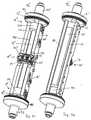
- FIG. 1shows a Coriolis mass flow / density transducer 10 after first variant of the invention and FIG. 2 thereof Cross section along the line A-A of Fig. 1.
- the mass flow / density transducer 10in the course one flowed through by a fluid to be measured
- Pipeline of a given diametercan be inserted and will connected to it in a fluid-tight manner before commissioning.
- Flanges 111, 121 shownwhich have a respective short pipe section 112, 122 with a respective end piece 113, 123 are connected, into which an inlet end 11 and an outlet end 12 of a single measuring tube 13 each ends and is fixed in it; the measuring tube is straight and has a longitudinal axis 131.
- the mass flow / density transducer 10can also instead of over the flanges 111, 121 via other common fasteners in the pipeline be inserted.
- Inlet end 11 and outlet end 12 of the measuring tube 13are on fixed to a carrier, e.g. in the form of an open or closed frame or a cylindrical tube 14 can be formed.
- the closed frame or that cylindrical tubecompletely surround the measuring tube 13 kind of wrapping.
- the measuring tube 13 and theare preferred End pieces 113, 123 and these and the carrier together welded.
- the beamhas a longitudinal line of gravity 141 that is parallel runs to the longitudinal axis 131 of the measuring tube 13, but not coincides with this. This non-congruence can be seen from Figs. 3 and 4, each one Sectional view along the line B-B of Fig. 1 and along the line C-C of Fig. 2.
- 1 to 4is a circular cylindrical tube 14 shown with a completely uniform wall thickness.
- the longitudinal center of gravity of the tube 14is therefore identical with its longitudinal axis, and measuring tube 13 and tube 14 are not because of the parallelism of their axes arranged concentrically or not coaxially to each other.
- a boom mass 15which is a disc can be with a hole by means of which the disc over the measuring tube 13 is pushed and fixed thereon.
- the disc in the illustrated embodiments one with the bore coaxial semicircle 151 with an integrally formed thereon Rectangular part 152has.
- the disks serving as cantilever mass 15 according to FIG. 2 to 5preferably have a thickness that is about half as large the diameter of the measuring tube 13 is.
- an excitation arrangement 16can be seen, which is approximately in the middle between the end pieces 113, 123 is arranged. It is e.g. an electromagnetic Exciter, for example one on the carrier or on the tube 14 attached coil assembly 161 and one on the Cantilever mass 15 includes permanent magnets 162.
- an electromagnetic Exciterfor example one on the carrier or on the tube 14 attached coil assembly 161 and one on the Cantilever mass 15 includes permanent magnets 162.
- the exciter arrangementcan also be designed as in is not shown for the sake of simplicity, that a first sub-arrangement is provided, which on the Measuring tube with a first excitation force in the direction of the Intersection of a longitudinal line of symmetry of the cantilever mass acts with the longitudinal axis of the measuring tube, and that further a second sub-arrangement is provided which is based on a End of the boom mass facing away from the measuring tube with one of the first excitation force opposite second Excitation force acts.
- the measuring tube 13is in the Operation excited to bending vibrations, the frequency of which is the same is the mechanical resonance frequency of the measuring tube. This is, as has been the case with Coriolis mass flow sensors for decades is known a measure of the density of the measuring fluid, cf. e.g. US-A 41 87 721. Others Details of vibration excitation are given below the explanation of FIGS. 12 and 13 still specified.
- FIGS. 2 to 4also show a respective sensor 17, 18 for the inlet and outlet movements of the Measuring tube 13 shown schematically, each in same distance between its center and the inlet or the outlet end 113 or 123 is arranged. It is preferably located at the location of the respective sensor the measuring tube 13 has an annular rib 132, 133.
- sensors 17, 18can be used for this purpose in the state the Coriolis mass flow / density transducer technique and Coriolis mass flow meters different types of sensors, such as Path-, Speed or acceleration sensors, e.g. work electrodynamically or optically.
- FIGS. 1 to 5each show in one of FIG. 1 corresponding sectional view different realizations a second embodiment of the first variant of Invention with regard to its clear width again circular cylindrical tube 14 ', but - in Contrary to the first embodiment according to FIGS. 1 to 5 has only a partially uniform wall thickness and its Longitudinal line of gravity therefore not with its longitudinal axis coincides.
- This longitudinal axis of the tube 14 'coincides with that Longitudinal axis of the measuring tube 13 together; so both pipes are 6 to 11 coaxially, although the tube 14 'none has uniform wall thickness.
- This collapseis but not mandatory: the two longitudinal axes can also run parallel to each other.
- Thiscan e.g. by fixing a longitudinal rib 142, esp. Welding or soldering, along the first Surface line can be reached. Width and height of the longitudinal rib as well as their material are taking into account the mass the cantilever mass 15 and the uniform wall thickness of the Tube 14 'to choose.
- the counterweight 143can again e.g. by welding or soldered onto the tube 14 ', or it can in a hole in the wall or a appropriate blind hole inserted and fixed in it become. Width, height and length of the counterweight 143 as well whose material are taking into account the mass of the Boom mass 15 and the uniform wall thickness of the Tube 14 'to choose.
- the wall of the tube 14 'along that of the boom mass 15 diametrically opposite first surface line only over two partial areas 144, 145 of the entire lengthare thicker than the otherwise uniform wall thickness of the tube 14 '.
- the Subareas 144, 145each extend from respective end of the tube 14 'forth to the center thereof and thus form a central area 146, which is the uniform Has wall thickness of the tube 14 '.
- the partial areas 144, 145can again e.g. by Welding or soldering on a corresponding rib the pipe 14 'are fixed. Width, height and length of the respective sub-area 144, 145 and its material taking into account the mass of the boom mass 15 and to choose the uniform wall thickness of the tube 14 '.
- the wall of the tube 14 'along one of the cantilever mass 15 adjacent second surface line along the entire length of the wallmade thinner than the otherwise uniform wall thickness.
- the wall of the tube 14 'alongthat of the cantilever mass 15 neighboring second surface line only in one Central area 147 opposite the boom mass 15 through Ablation made thinner; otherwise the tube 14 ' the uniform wall thickness.
- the wall of the tube 14 'alongthat of the cantilever mass 15 neighboring second surface line only over two partial areas 148, 149 of the entire length thinner than the rest uniform wall thickness of the tube 14 'made.
- the Subareas 148, 149each extend from respective end of the tube 14 'forth to the center thereof and thus form a central area 150, which is the uniform Has wall thickness of the tube 14 '.
- FIGS. 12 and 13first remembered that one at two clamping points fixed and in between excited to bending vibrations Pipe without cantilever dimensions a single bending mode Has.
- the tubevibrates like a string with its basic resonance frequency, which in the theory of Vibrations also as a fundamental or first harmonic is designated and which is the lowest in number is.
- the stringhas and also the pipe between the two clamping points only antinode and therefore no one in between Vibration node; rather, these are only at the clamping points.
- This first basic mode of bending vibrationhas one of the above corresponding resonance frequency mentioned - "first" - Resonance frequency, which is numerically the lowest possible is; for a specific measuring tube with a given Diameter, predetermined length and wall thickness as well as with given boom dimensions and their dimensioning is e.g. 400 Hz.
- Fig. 13shows the conditions for the mentioned second bending mode, in which the Cantilever mass 15 around the axis of the measuring tube 13 to the right moved inside when the measuring tube moves to the left, or moves to the left inside when the measuring tube moves to the right emotional.
- the boom massrotates significantly in each case inside.
- the torsional vibration axis of this torsional vibrationis obviously not the same as the axis of the measuring tube, but is parallel to it.
- the torsional vibration axisis the same the line of gravity of all mechanical masses connected to the Vibrations in the second bending mode involved. These are the mass of the measuring tube incl Mass of the fluid, mass of the boom mass and mass of the fixed and resonating parts of the Exciter arrangement and possibly the first parts of the brake arrangement to be explained below.
- a possible piercing pointis the Torsional vibration axis through the drawing plane with X designated; as drawn, it lies on the vertical Center line of the cantilever mass if the mass of the Exciter arrangement symmetrical to this center line is arranged.
- the penetration point Xmigrates into Slightly depending on the density of the fluid forth.
- the second bending modehas a - "second" - Resonance frequency greater than that defined above - "first" - resonance frequency of the first bending mode is; for the specified measuring tube mentioned it is 900 Hz.
- the measuring tube 13is always closed Vibrations of the second bending mode excited in which the boom mass 15 to the measuring tube moves when this moves outward like this in Fig. 13 is shown and has been explained above.
- the resonance frequency of the second fundamental bending mode about twice the resonance frequency of the first bending modeis made can be used to feed the Exciter arrangement 16 of course required Excitation circuit in the form of a phase-locked loop, cf. e.g. the US-A 48 01 897, easily dimension such that it only stimulates the second bending mode.
- the mass flow / density transducer 10 'of FIG. 14is the measuring tube 13 'excited to the vibrations via the Inlet and outlet ends by means of one each of equal length, straight and aligned with the measuring tube 13 ' Pipe section 13 ", 13 * extended.
- the respective free end the pipe sections 13 ", 13 *is fixed in a housing 19.
- the housing 19comprises e.g. the flanges 111, 121 of FIG. 1 corresponding flanges 111 ', 121'.
- a second Variant of a Coriolis mass flow / density sensor 10according to the invention. It has a only straight, an inlet end 11 "and an outlet end 12" having measuring tube 13 ". At the inlet end is a Measuring tube 13 "completely surrounding inlet plate 213 and at The outlet end also surrounds the measuring tube 13 " Outlet plate 223 fixed.
- first carrier plate 24fixed parallel to one the first surface line 134 of the measuring tube 13 ".
- second Carrier plate 34fixed parallel to one of the first Surface line 134 diametrically opposite second Surface line 234 of the measuring tube runs. So are each other facing side surfaces of the two carrier plates 24, 34 also parallel to each other.
- one of the counterweightsis used Boom mass 15 "opposite longitudinal rod 25, the the first and second carrier plates 24, 34 is fixed.
- the longitudinal bar 25extends in FIGS. 15 and 16 practically parallel to the entire oscillatable length of the Measuring tube 13 "; however, this is not mandatory, but only so in this embodiment.
- the system of the two carrier plates 24, 34, the Inlet plate 213, outlet plate 223 and longitudinal rod 25has a longitudinal line of gravity parallel to the axis of the Measuring tube 13 "runs. With regard to this property 15 and 16 with the arrangement of 1 to 5 comparable.
- the measuring tube 13is always from an excitation arrangement 16" in vibrations of the second bending mode offset, which acts on the boom mass 15 "and thus again roughly in the middle between the inlet and outlet ends is arranged. Particular details of the pathogen arrangement will be explained in connection with Fig. 17.
- the inlet and outlet movements of the measuring tube 13are each with a sensor 17" or 18 " sampled, each at the same distance between the Middle of the measuring tube and the inlet or outlet end is arranged.
- the second variant shown in FIGS. 15 and 16is comparable in structure to its mechanical vibration system with the development of the first variant in FIG. 14.
- the measuring tube 13"is extended beyond the inlet and outlet ends by means of a pipe section 13 # , 13 + of equal length, straight and aligned with the measuring tube 13".
- FIG 17shows a perspective top view and FIG compared to Fig. 15 enlarged scale the boom mass 15 "and the excitation arrangement 16" and others, this preferably assigned parts.
- the boom mass 15formed as a disc. It has a front surface 154 and a parallel one in 15 and 17, however, hidden rear surface.
- the Boom mass 15also has a hole by means of which Washer pushed over the measuring tube 13 "and fixed thereon is.
- the discis - similar to the arrangement of the 1 to 4 - from a coaxial with the bore Circular segment 151 "with a rectangular part molded onto it 152 ". From a diameter of the measuring tube 13" is one Side surface 155 of the rectangular part 152 "centrally cut; this side surface is only one in FIG. 17 small part, namely in the bores of a bar 163 see.
- the bar 163is covered again Fastening surface fixed to the side surface 155; to used screws can be seen in Fig. 15.
- the bar 163is longer than the side surface 155 and has one protruding first bar end 163 'with a continuation the mounting surface as well as a second overhanging it Bar end 163 "with a continuation of the Mounting surface.
- the excitation arrangement 16consists of a Continuation of the mounting surface of the first beam end 163 'fixed first excitation system 26 and from one at the Continuation of the mounting surface of the second beam end 163 "fixed second excitation system 36.
- the first or the second excitation system 26 and 36contains one at the Carrier plate 24 or 34 fixed first or second coil. During operation, these are opposed by an excitation current flowed through.
- the coilsact with a first or a second permanent magnet together, which at the bar end 163 'or 163 "is fixed.
- a preferred further developmentis to suppress vibration modes other than the second bending vibration basic mode, esp. to suppress the first Bending mode and its harmonics, a first and a second part 27, 37 one on the Eddy current principle based brake arrangement provided.
- the first part 27is on the front surface 154 of the disc fixed, in an area where the above explained Torsional vibration axis of the mechanical Torsional vibration system one possible in operation Point of penetration through the front surface 154.
- a second part of the first brake arrangement, which is shown in FIG. 15is hardly recognizable and therefore not with one Reference number is provided - the reference number 28 should be - is on one on the first and the second Carrier plate 24, 34 fixed first bracket 29 attached; this is only shown in FIG. 15, in FIG. 17 however for a better view of the boom mass 15 "etc. omitted.
- a second part 38is the second Brake arrangement on one on the first and the second Carrier plate 24, 34 fixed second bracket 39 attached.
- the fixation on the carrier plate 24 or 34is carried out as can be seen by means of angled "feet".
- the two Mountsare preferably made of soft magnetic Material.
- the first two parts 27, 37 of the brake assembliescontain circular cylindrical permanent magnets, of which in 17 only the permanent magnet 271 together with a associated bracket 272 can be seen.
- the second two Parts of the brake assembliesare copper disks.
- the current positionis thus determined by means of the brake arrangements the torsional vibration axis stabilized above. It is thus prevented that another Vibration mode, especially the first bending mode and its harmonics and / or such Harmonics of the second bending mode, which has a different axis of torsional vibration than the latter have, kindle and can wiggle.
- the excitement of the first bending modeis achievable through another phase-locked loop that is on the first resonance frequency works.
- the sensors generated signalsin this case contain both Coriolis effect-related phase shift proportion of the Vibrations of the second resonance frequency as well Coriolis effect-related phase shift proportion of the Vibrations of the first resonance frequency. Because these two Resonance frequencies are around a factor of 2 can be distinguished, the two phase shift components easily disconnect electronically.
Landscapes
- Physics & Mathematics (AREA)
- General Physics & Mathematics (AREA)
- Fluid Mechanics (AREA)
- Health & Medical Sciences (AREA)
- Life Sciences & Earth Sciences (AREA)
- Chemical & Material Sciences (AREA)
- Analytical Chemistry (AREA)
- Biochemistry (AREA)
- General Health & Medical Sciences (AREA)
- Immunology (AREA)
- Pathology (AREA)
- Measuring Volume Flow (AREA)
Description
Translated fromGermanDie Erfindung betrifft Coriolis-Massedurchfluß/Dichte-Aufnehmermit einem einzigen geraden Meßrohr.The invention relates to Coriolis mass flow / density transducerswith a single straight measuring tube.
In der EP-A 469 448 ist Coriolis-Massedurchfluß/Dichte-Aufnehmer,der in eine Rohrleitung einfügbar ist und imBetrieb von einem zu messenden Fluid durchströmt wird,
- mit einem einzigen geraden, ein Einlaßende und einAuslaßende aufweisenden Meßrohr,
- mit einem am Einlaßende und am Auslaßende fixierten,torsions- und biegestiefen Tragsystem,
- mit einem Pendelarm,
- der in der Mitte zwischen dem Einlaß- und dem Auslaßendeam Meßrohr fixiert ist,
- mit einer im Endbereich des Pendelarms angebrachtenEigenfrequenzeinstellmasse,
- mit einer auf den Pendelarm einwirkenden und somit dasMeßrohr in Schwingungen versetzenden Erregeranordnung,und
- mit jeweils einem Sensor für die einlaß- bzw. dieauslaßseitigen Bewegungen des Meßrohrs, der jeweils imgleichen Abstand zwischen dessen Mitte und dem Einlaß-bzw. dem Auslaßende angeordnet ist.
- with a single straight measuring tube having an inlet end and an outlet end,
- with a torsion and bending-deep support system fixed at the inlet and outlet ends,
- with a pendulum arm,
- which is fixed in the middle between the inlet and the outlet end on the measuring tube,
- with a natural frequency adjustment mass attached in the end area of the pendulum arm,
- with an exciter arrangement acting on the pendulum arm and thus causing the measuring tube to vibrate, and
- each with a sensor for the inlet and outlet side movements of the measuring tube, which is arranged at the same distance between its center and the inlet and outlet ends.
Aufgrund des Pendelarms werden nicht nur Biegeschwingungen,sondern auch Torsionsschwingungen des einzigen Meßrohrserregt, so daß nicht nur nicht der Massedurchfluß und/oderdie Dichte des Meßfluids, sondern auch dessen Viskositätmeßbar ist. Das von Meßrohr und Pendelarm gebildeteSchwingungssystem wird auf seiner Grundresonanzfrequenzerregt.Due to the pendulum arm, not only bending vibrations,but also torsional vibrations of the single measuring tubeexcited so that not only not the mass flow and / orthe density of the measuring fluid, but also its viscosityis measurable. The one formed by measuring tube and pendulum armVibration system is based on its fundamental resonance frequencyexcited.
In der US-A 55 31 126, die der WO-A 95/03528 entspricht,ist ferner ein Coriolis-Massedurchfluß/Dichte-Aufnehmerbeschrieben, der in eine Rohrleitung mittels eines einlaß-und eines auslaßseitigen Anschlußelements einfügbar ist undim Betrieb von einem zu messenden Fluid durchströmt wird,
- mit einem einzigen geraden, eine Längsachse aufweisenden,zwischen den Anschlußelementen verlaufenden und daranfixierten Meßrohr,
- mit einem zum Meßrohr parallelen, geraden, nicht-durchflossenenBlindrohr,
- mit einer einlaßseitigen und einer auslaßseitigenKnotenplatte,
- deren eine den einlaßseitigen Endteil des Meßrohrsam entsprechenden Endteil des Blindrohrs und
- deren andere den auslaßseitigen Endteil desMeßrohrs am entsprechenden Endteil des Blindrohrsjeweils nebeneinander fixiert,
- mit einem als Träger dienenden Trägerrohr, dessenjeweiliges Ende am jeweiligen Anschlußelement fixiert istund von dem eine Längs-Symmetrieachse parallel zurLängsachse des Meßrohrs verläuft,
- mit Mitteln, die nur am Blindrohr zur Erregung vonBiegeschwingungen des Meßrohrs angreifen, deren Frequenzjedoch nicht mit der Resonanzfrequenz des Meßrohrsidentisch ist, wobei Meßrohr und Blindrohr gegenphasigzueinander schwingen.
- with a single straight measuring tube, which has a longitudinal axis, runs between the connecting elements and is fixed thereon,
- with a straight, non-flowing blind pipe parallel to the measuring tube,
- with an inlet-side and an outlet-side node plate,
- one of which is the inlet-side end part of the measuring tube at the corresponding end part of the dummy tube and
- the other of which fixes the outlet-side end part of the measuring tube next to one another at the corresponding end part of the dummy tube,
- with a carrier tube serving as a carrier, the respective end of which is fixed to the respective connection element and of which a longitudinal axis of symmetry runs parallel to the longitudinal axis of the measuring tube,
- with means which only act on the dummy tube to excite bending vibrations of the measuring tube, but whose frequency is not identical to the resonance frequency of the measuring tube, the measuring tube and dummy tube oscillating in phase opposition to one another.
Dieser vorbeschriebene Coriolis-Massedurchfluß/Dichte-Aufnehmerist bei gegebener Dimensionierung nur in einemschmalen Bereich von Dichtewerten - etwa ± 5% einer Nenn-Dichte- mechanisch ausbalanciert, d.h. nur bei diesenDichtewerten werden von den Schwingungen des Meßrohrsherrührende Kräfte über die Anschlußelemente praktischnicht auf die Rohrleitung übertragen. Der erwähnte Bereichwird durch die Erregung "neben" der Resonanzfrequenz zwarerweitert, es ist jedoch eine erheblich größere Erregungsenergie erforderlich als bei Resonanz-Erregung. Jeweniger ausbalanciert der Massedurchfluß/Dichte-Aufnehmerist, um so mehr werden Kräfte und Schwingungsenergie aufdie Rohrleitung übertragen; somit geht aberSchwingungsenergie verloren und die Meßungenauigkeit wirdgrößer.This Coriolis mass flow / density transducer described aboveis given in one dimension onlynarrow range of density values - about ± 5% of a nominal density- mechanically balanced, i.e. only with theseDensity values are determined by the vibrations of the measuring tubeforces originating from the connection elements practicallynot transferred to the pipeline. The area mentionedis due to the excitation "next to" the resonance frequencyexpanded, but it's a much larger oneExcitation energy required than for resonance excitation. Eachthe mass flow / density sensor is less balancedis, the more forces and vibrational energy are ontransfer the pipeline; so it worksVibration energy is lost and the measurement inaccuracygreater.
Diese Unbalance macht sich nicht nur bei der temperaturbedingtenDichteänderung ein und desselben Fluids störendbemerkbar, sondern auch ganz besonders bei der Messung vonunterschiedlichen Fluiden, die in der Rohrleitung zuunterschiedlichen Zeiten, z.B. nacheinander, fließen.This imbalance is not only caused by the temperature-relatedDensity change of the same fluid disturbingnoticeable, but also especially when measuringdifferent fluids in the pipeline toodifferent times, e.g. successively, flow.
Da Coriolis-Massedurchfluß/Dichtemesser für die Messungeiner möglichst umfangreichen Palette von untereinandersehr verschiedenen Fluiden mit den unterschiedlichstenDichten geeignet sein sollen, ist es somit wichtig,Coriolis-Massedurchfluß/Dichte-Aufnehmer zu schaffen, dieüber einen weiten Dichtebereich im erwähnten Sinneausbalanciert sind und somit genau messen.Since Coriolis mass flow / density meter for the measurementthe widest possible range of each othervery different fluids with the most variedDensities, it is important toCoriolis mass flow / density transducers to create thatover a wide range of density in the sense mentionedare balanced and therefore measure accurately.
Hierzu besteht eine erste Variante bzw. zweite Variante derErfindung in dem in Anspruch 1 bzw. Anspruch 10 definiertenCoriolis-Massedurchfluß/Dichte-Aufnehmer.There is a first variant or second variant of theInvention in that defined in claim 1 or claim 10Coriolis mass flow / density transducer.
Vorteilhafte Ausgestaltungen oder Weiterbildungen derbeiden Varianten der Erfindung sind in den abhängigenAnsprüchen 2 bis 9 und 11 bis 16 definiert.Advantageous refinements or developments oftwo variants of the invention are in the dependentClaims 2 to 9 and 11 to 16 defined.
Ein Vorteil der Erfindung besteht u.a. darin, daß dieMeßgenauigkeit der Massedurchflußmessung über einen weitenDichtebereich (0 kg/m3 bis 3.000 kg/m3) hervorragend gutist - 0 kg/m3 entspricht dabei einer Messung des Nullpunktsder Massedurchflußmessung mit einem Vakuum im Meßrohr. AnMassedurchfluß/Dichte-Aufnehmern einer Pilotserie wurdenz.B. Genauigkeiten im Bereich von 0,1% vom Meßwertermittelt.One advantage of the invention is that the measurement accuracy of the mass flow measurement over a wide density range (0 kg / m3 to 3,000 kg / m3 ) is outstandingly good - 0 kg / m3 corresponds to a measurement of the zero point of the mass flow measurement with a vacuum in the measuring tube. For example, accuracies in the range of 0.1% of the measured value were determined on mass flow / density sensors of a pilot series.
Ferner ist ein weiterer wichtiger Vorteil der Erfindung,daß auch die Viskosität des Fluids gut meßbar ist, was aufden folgenden, dem Durchschnittsfachmann geläufigenSachverhalten beruht:Another important advantage of the invention isthat the viscosity of the fluid is well measurable, which isthe following, familiar to those of ordinary skill in the artFacts are based on:
Die Viskosität eines Fluids ist mit einemCoriolis-Massedurchfluß/Dichte-Aufnehmer nur meßbar, wenn dessenMeßrohr bzw. dessen Meßrohre (auch) eine Drehschwingungausführt bzw. ausführen, so daß auf das Fluid Scherkräfteausgeübt werden. Bei zu Biegeschwingungen erregten geradenMeßrohren treten überhaupt keine Drehschwingungen und somitkeine Scherkräfte auf.The viscosity of a fluid is oneCoriolis mass flow / density transducers can only be measured if thisMeasuring tube or its measuring tubes (also) a torsional vibrationexecutes or execute so that shear forces on the fluidbe exercised. In the case of straight lines excited by bending vibrationsMeasuring tubes do not experience any torsional vibrations at all and thereforeno shear forces.
Bei ausleger-artig gebogenen, insb. U-förmigen, Meßrohrentreten zwar Drehschwingungen auf, deren Amplitude istjedoch so gering, daß eine Messung der Viskosität kaummöglich ist. Patentdokumente, in denen die Viskosität inZusammenhang mit Coriolis-Massedurchfluß/Dichte-Aufnehmernüberhaupt erwähnt ist, sind nicht sehr zahlreich.With boom-like, especially U-shaped, measuring tubestorsional vibrations occur, the amplitude of which ishowever, so low that hardly any measurement of the viscosityis possible. Patent documents in which the viscosity inConnection with Coriolis mass flow / density sensorsmentioned at all are not very numerous.
So erwähnt z.B. die US-A 49 38 075 lediglich die Navier-Stokes-Gleichung,in der u.a. die Scherviskosität vorkommt,die jedoch nicht gemessen wird. Andere Patentschriftenhandeln lediglich von der Viskositätskompensation dergemessenen Werte des Massedurchflusses, vgl. z.B. dieUS-A 50 27 662, die US-A 48 76 879 und die US-A 48 72 351.For example, US-A 49 38 075 only the Navier-Stokes equation,in the u.a. the shear viscosity occurs,which, however, is not measured. Other patentsare only about the viscosity compensation of themeasured values of mass flow, cf. e.g. theUS-A 50 27 662, US-A 48 76 879 and US-A 48 72 351.
Einrohr-Coriolis-Massedurchfluß/Dichte-Aufnehmerentsprechend der Erfindung führen nun nicht nur die für dieMassedurchfluß- und Dichtemessung erforderliche undbeabsichtigte Biegeschwingung, sondern auch wegen derAuslegermasse im zweiten Biegeschwingungs-Grundmode eineDrehschwingung um eine Drehschwingungsachse aus, deren Lageunten näher erläutert ist.Single tube Coriolis mass flow / density transduceraccording to the invention now lead not only to thatMass flow and density measurement required andintended bending vibration, but also because of theBoom dimensions in the second bending mode oneTorsional vibration about a torsional vibration axis, its positionis explained in more detail below.
Die Amplitude dieser Drehschwingung ist bei der Erfindungnun so ausreichend groß, daß zusätzlich zum Massedurchflußund der Dichte auch noch die Viskosität des Fluids gemessenwerden kann, und zwar mit lediglich geringfügigem Aufwandan zusätzlicher Elektronik.The amplitude of this torsional vibration is in the inventionnow sufficiently large that in addition to the mass flowand the density also measured the viscosity of the fluidcan be, with only a little effortof additional electronics.
Für diese Viskositätsmessung kann auf in der Literaturlängst beschriebene Verfahren zurückgegriffen werden, diediese Messung in Verbindung mit der Dichtemessung vonFluiden mittels schwingender mechanischer Anordnungen,insb. Rohren, diskutieren.For this viscosity measurement can be found in the literaturelong-described methods are used thatthis measurement in connection with the density measurement ofFluids by means of vibrating mechanical arrangements,especially pipes, discuss.
So kann z.B. nach der Zeitschrift "IEEE Transactions onIndustrial Electronics and Control Instrumentation", August1980, Seiten 247 bis 253 die Viskosität bestimmt werden,wenn der Resonanz-Gütefaktor der schwingenden mechanischenAnordnung incl. des Fluids gemessen wird. Dies kann z.B.durch die Messung des elektrischen Stromes erfolgen, mitdem diese erregt wird.For example, after the magazine "IEEE Transactions onIndustrial Electronics and Control Instrumentation ", August1980, pages 247 to 253 the viscosity can be determined,if the resonance figure of merit of the vibrating mechanicalArrangement including the fluid is measured. This can e.g.by measuring the electric current withwhich is excited.
Die Erfindung wird nun anhand von in den Figuren derZeichnung dargestellten Ausführungsbeispielen nähererläutert. In den Figuren sind gleiche Teile mit denselbenBezugszeichen versehen.
- Fig. 1 zeigt
- eine teilweise geschnittene Längsansichteiner ersten Ausgestaltung eines Coriolis-Massedurchfluß/Dichte-Aufnehmersnach derersten Variante der Erfindung,
- Fig. 2 zeigt
- eine entlang der Linie A-A von Fig. 1geschnittene Ansicht,
- Fig. 3 zeigt
- eine entlang der Linie B-B von Fig. 1geschnittene Ansicht,
- Fig. 4 zeigt
- eine entlang der Linie C-C von Fig. 2geschnittene Ansicht,
- Fig. 5 zeigt
- eine mit Fig. 3 vergleichbare Schnittansichteiner Abwandlung des Coriolis-Massedurchfluß/Dichte-Aufnehmersder Fig. 1bis 4,
- Fig. 6 zeigt
- eine der Fig. 1 entsprechende Schnittansichteiner ersten Realisierung einer zweitenAusgestaltung der ersten Variante,
- Fig. 7 zeigt
- eine der Fig. 1 entsprechende Schnittansichteiner zweiten Realisierung der zweitenAusgestaltung der ersten Variante,
- Fig. 8 zeigt
- eine der Fig. 1 entsprechende Schnittansichteiner dritten Realisierung der zweitenAusgestaltung der ersten Variante,
- Fig. 9 zeigt
- eine der Fig. 1 entsprechende Schnittansichteiner vierten Realisierung der zweitenAusgestaltung der ersten Variante,
- Fig. 10 zeigt
- eine der Fig. 1 entsprechende Schnittansichteiner fünften Realisierung der zweitenAusgestaltung der ersten Variante,
- Fig. 11 zeigt
- eine der Fig. 1 entsprechende Schnittansichteiner sechsten Realisierung der zweitenAusgestaltung der ersten Variante,
- Fig. 12 zeigt
- schematisch das Schwingungsverhalten vonMeßrohr und Auslegermasse im bei derErfindung verwendbaren erstenBiegeschwingungs-Grundmode,
- Fig. 13 zeigt
- schematisch das Schwingungsverhalten vonMeßrohr und Auslegermasse im bei derErfindung immer verwendeten zweitenBiegeschwingungs-Grundmode,
- Fig. 14 zeigt
- eine Weiterbildung der ersten Variante derErfindung in einer mit Fig. 2 vergleichbarenSchnittansicht.
- Fig. 15 zeigt
- in perspektivischer Draufsicht einenCoriolis-Massedurchfluß/Dichte-Aufnehmernach der zweiten Variante der Erfindung,
- Fig. 16 zeigt
- in perspektivischer Unteransicht denCoriolis-Massedurchfluß/Dichte-Aufnehmer vonFig. 15, und
- Fig. 17 zeigt
- in perspektivischer Draufsicht und ingegenüber Fig. 15 vergrößertem Maßstab einwichtiges Detail dieser Figur.
- Fig. 1 shows
- 2 shows a partially sectioned longitudinal view of a first embodiment of a Coriolis mass flow / density sensor according to the first variant of the invention,
- Fig. 2 shows
- 2 shows a sectional view along the line AA in FIG. 1,
- Fig. 3 shows
- 2 shows a sectional view along line BB of FIG. 1,
- Fig. 4 shows
- 3 shows a view cut along the line CC in FIG. 2,
- Fig. 5 shows
- 3 shows a sectional view comparable to FIG. 3 of a modification of the Coriolis mass flow / density sensor of FIGS. 1 to 4,
- Fig. 6 shows
- 1 shows a sectional view corresponding to FIG. 1 of a first implementation of a second embodiment of the first variant,
- Fig. 7 shows
- 1 shows a sectional view corresponding to FIG. 1 of a second implementation of the second embodiment of the first variant,
- Fig. 8 shows
- 1 shows a sectional view corresponding to FIG. 1 of a third implementation of the second embodiment of the first variant,
- Fig. 9 shows
- 1 shows a sectional view corresponding to FIG. 1 of a fourth implementation of the second embodiment of the first variant,
- Fig. 10 shows
- 1 shows a sectional view corresponding to FIG. 1 of a fifth implementation of the second embodiment of the first variant,
- Fig. 11 shows
- 1 shows a sectional view corresponding to FIG. 1 of a sixth implementation of the second embodiment of the first variant,
- Fig. 12 shows
- schematically the vibration behavior of measuring tube and boom mass in the first bending vibration basic mode usable in the invention,
- 13 shows
- schematically the vibration behavior of measuring tube and boom mass in the second bending vibration basic mode always used in the invention,
- Fig. 14 shows
- a development of the first variant of the invention in a sectional view comparable to FIG. 2.
- 15 shows
- a perspective top view of a Coriolis mass flow / density sensor according to the second variant of the invention,
- Fig. 16 shows
- in perspective bottom view of the Coriolis mass flow / density sensor of Fig. 15, and
- Fig. 17 shows
- in perspective top view and on an enlarged scale compared to FIG. 15, an important detail of this figure.
Die teilweise geschnittene Längsansicht der Fig. 1 zeigteinen Coriolis-Massedurchfluß/Dichte-Aufnehmer 10 nach derersten Variante der Erfindung und die Fig. 2 dessenQuerschnitt entlang der Linie A-A von Fig. 1. Bei Benutzungist der Massedurchfluß/Dichte-Aufnehmer 10 in den Verlaufeiner von einem zu messenden Fluid durchströmten, ausGründen der Übersichtlichkeit jedoch nicht dargestelltenRohrleitung eines gegebenen Durchmessers einfügbar und wirdmit ihr vor der Inbetriebnahme fluiddicht verbunden.The partially sectioned longitudinal view of FIG. 1 showsa Coriolis mass flow /
In den Fig. 1 und 2 sind zu diesem Zweck entsprechendeFlansche 111, 121 dargestellt, die über ein jeweiligeskurzes Rohrstück 112, 122 mit einem jeweiligen Endstück113, 123 verbunden sind, in das bzw. in dem ein Einlaßende 11 und ein Auslaßende 12 eines einzigen Meßrohrs 13 jeweilsmündet und darin fixiert ist; das Meßrohr ist gerade undhat eine Längsachse 131. Der Massedurchfluß/Dichte-Aufnehmer10 kann anstatt über die Flansche 111, 121 auchüber andere übliche Befestigungsmittel in die Rohrleitungeingefügt werden.1 and 2 are corresponding for this purposeFlanges 111, 121 shown, which have a respective
Einlaßende 11 und Auslaßende 12 des Meßrohrs 13 sind aneinem Träger fixiert, der z.B. in der Form eines offenenoder geschlossenen Rahmens oder eines zylindrischen Rohres14 ausgebildet sein kann. Der geschlossene Rahmen oder daszylindrische Rohr umgeben das Meßrohr 13 vollständig nachArt einer Umhüllung. Bevorzugt sind das Meßrohr 13 und dieEndstücke 113, 123 sowie diese und der Träger miteinanderverschweißt.
Der Träger hat eine Längs-Schwerelinie 141, die parallelzur Längsachse 131 des Meßrohrs 13 verläuft, jedoch nichtmit dieser zusammenfällt. Diese Nicht-Deckungsgleichheitist aus den Fig. 3 und 4 ersichtlich, die jeweils eineSchnittansicht entlang der Linie B-B von Fig. 1 bzw.entlang der Linie C-C von Fig. 2 zeigen.The beam has a longitudinal line of
In den Fig. 1 bis 4 ist jeweils ein kreiszylindrisches Rohr14 mit vollständig einheitlicher Wandstärke dargestellt.Die Längs-Schwerelinie des Rohres 14 ist daher identischmit seiner Längsachse, und Meßrohr 13 sowie Rohr 14 sindwegen der erwähnten Parallelität ihrer Achsen nichtkonzentrisch bzw. nicht koaxial zueinander angeordnet.1 to 4 is a circular
In der Mitte zwischen den Endstücken 113, 123 ist amMeßrohr 13 eine Auslegermasse 15 fixiert, die eine Scheibemit einer Bohrung sein kann, mittels der die Scheibe überdas Meßrohr 13 geschoben und darauf fixiert ist. In denFig. 3 und 4 ist zu sehen, daß die Scheibe in den darindargestellten Ausführungsbeispielen einen mit der Bohrung koaxialen Halbkreisring 151 mit einem daran angeformtenRechteckteil 152 aufweist.In the middle between the
In Fig. 5, die einen mit den Fig. 3 und 4 vergleichbarenQuerschnitt zeigt, ist dargestellt, daß die Auslegermasseauch eine Kreisscheibe 153 sein kann, die mittels eineraußermittig angebrachten Bohrung über das Meßrohr 13geschoben und darauf fixiert ist. Kreisscheibe 153 undMeßrohr 13 sind somit nicht konzentrisch angeordnet.5, which is comparable to that of FIGS. 3 and 4Cross section shows that the boom mass is showncan also be a
Die als Auslegermasse 15 dienenden Scheiben nach den Fig. 2bis 5 haben bevorzugt eine Dicke, die etwa halb so groß wieder Durchmesser des Meßrohrs 13 ist.The disks serving as
In den Fig. 2 bis 4 ist eine Erregeranordnung 16 zu sehen,die etwa in der Mitte zwischen den Endstücken 113, 123angeordnet ist. Sie ist z.B. ein elektromagnetischerErreger, der beispielsweise eine am Träger bzw. am Rohr 14befestigte Spulenanordnung 161 und einen an derAuslegermasse 15 befestigten Dauermagneten 162 umfaßt.2 to 4, an
Als Erregeranordnung können die für diesen Zweck im Standder Technik von Coriolis-Massedurchfluß/Dichte-Aufnehmernund Coriolis-Massedurchflußmessern beschriebenenverschiedenen Arten von Erregeranordnungen dienen.As a pathogen arrangement can be used for this purpose in the statethe Coriolis mass flow / density transducer techniqueand Coriolis mass flow metersserve different types of excitation arrangements.
Die Erregeranordnung kann auch so ausgebildet sein, was inden Figuren der Einfachheit halber nicht dargestellt ist,daß eine erste Teilanordnung vorgesehen ist, die auf dasMeßrohr mit einer ersten Erregerkraft in Richtung auf denSchnittpunkt einer Längs-Symmetrielinie der Auslegermassemit der Längsachse des Meßrohrs einwirkt, und daß fernereine zweite Teilanordnung vorgesehen ist, die auf einmeßrohr-abgewandtes Ende der Auslegermasse mit einer der ersten Erregerkraft entgegengerichteten zweitenErregerkraft einwirkt.The exciter arrangement can also be designed as inis not shown for the sake of simplicity,that a first sub-arrangement is provided, which on theMeasuring tube with a first excitation force in the direction of theIntersection of a longitudinal line of symmetry of the cantilever massacts with the longitudinal axis of the measuring tube, and that furthera second sub-arrangement is provided which is based on aEnd of the boom mass facing away from the measuring tube with one of thefirst excitation force opposite secondExcitation force acts.
Mittels der Erregeranordnung 16 wird das Meßrohr 13 imBetrieb zu Biegeschwingungen erregt, deren Frequenz gleichder mechanischen Resonanzfrequenz des Meßrohrs ist. Dieseist, wie seit Jahrzehnten auch bei Coriolis-Massedurchfluß-Aufnehmernbekannt ist, ein Maß für die Dichte des zumessenden Fluids, vgl. z.B. die US-A 41 87 721. WeitereEinzelheiten zur Schwingungsanregung werden unten anhandder Erläuterung der Fig. 12 und 13 noch angegeben.The measuring
In den Fig. 2 bis 4 ist ferner ein jeweiliger Sensor 17, 18für die einlaß- bzw. die auslaßseitigen Bewegungen desMeßrohrs 13 schematisch dargestellt, der jeweils imgleichen Abstand zwischen dessen Mitte und dem einlaß- bzw.dem auslaßseitigen Endstück 113 bzw. 123 angeordnet ist.Bevorzugt befindet sich am Ort des jeweiligen Sensors aufdem Meßrohr 13 eine ringförmige Rippe 132, 133.FIGS. 2 to 4 also show a
Als Sensoren 17, 18 können die für diesen Zweck im Standder Technik von Coriolis-Massedurchfluß/Dichte-Aufnehmernund Coriolis-Massedurchflußmessern beschriebenenverschiedenen Arten von Sensoren dienen, wie z.B. Weg-,Geschwindigkeits- oder Beschleunigungssensoren, die z.B.elektrodynamisch oder optisch arbeiten.As
Die Fig. 6 bis 11 zeigen jeweils in einer der Fig. 1entsprechenden Schnittansicht verschiedene Realisierungeneiner zweiten Ausgestaltung der ersten Variante derErfindung mit einem hinsichtlich seiner lichten Weitewieder kreiszylindrischen Rohr 14', das jedoch - imGegensatz zur ersten Ausgestaltung nach den Fig. 1 bis 5 -nur eine teilweise einheitliche Wandstärke hat und dessen Längs-Schwerelinie somit nicht mit dessen Längsachsezusammenfällt.6 to 11 each show in one of FIG. 1corresponding sectional view different realizationsa second embodiment of the first variant ofInvention with regard to its clear widthagain circular cylindrical tube 14 ', but - inContrary to the first embodiment according to FIGS. 1 to 5has only a partially uniform wall thickness and itsLongitudinal line of gravity therefore not with its longitudinal axiscoincides.
Diese Längsachse des Rohres 14' fällt andererseits mit derLängsachse des Meßrohrs 13 zusammen; beide Rohre sind alsoin den Fig. 6 bis 11 koaxial, obwohl das Rohr 14' keineeinheitliche Wandstärke hat. Dieses Zusammenfallen istjedoch nicht zwingend: Die beiden Längsachsen können auchparallel zueinander verlaufen.This longitudinal axis of the tube 14 ', on the other hand, coincides with thatLongitudinal axis of the measuring
Die erfindungswesentlich zwingende Parallelität vonLängsachse des Meßrohrs 13 und Längs-Schwerelinie desTrägers, insb. des Rohres 14', ergibt sich bei denRealisierungen der Fig. 6 bis 11 durch die nicht-einheitlicheWandstärke des Rohres 14'. Dadurch wirdnämlich erreicht, daß dessen Rohrwand zur Auslegermasse 15eine Gegenmasse bildet, mittels der die von derAuslegermasse erzeugte Unwucht kompensiert wird.The parallelism of essential to the inventionLongitudinal axis of the measuring
Bei der ersten Realisierung der Gegenmasse nach Fig. 6 istdie Wand des Rohres 14' längs einer der Auslegermasse 15diametral gegenüberliegenden ersten Mantellinie über diegesamte Länge dicker als die ansonsten einheitlicheWandstärke. Dies kann z.B. durch Fixieren einer Längsrippe142, insb. Aufschweißen oder Auflöten, entlang der erstenMantellinie erreicht werden. Breite und Höhe der Längsrippesowie deren Material sind unter Berücksichtigung der Masseder Auslegermasse 15 und der einheitlichen Wandstärke desRohres 14' zu wählen.In the first realization of the counter mass according to FIG. 6the wall of the tube 14 'along one of the
Bei der zweiten Realisierung der Gegenmasse nach Fig. 7 istdie Wand des Rohres 14' längs der der Auslegermasse 15diametral gegenüberliegenden ersten Mantellinie nur ineinem Bereich gegenüber der Auslegermasse 15 durch ein dortfixiertes Gegengewicht 143 verdickt.In the second realization of the counter mass according to FIG. 7the wall of the tube 14 'along that of the
Das Gegengewicht 143 kann wieder z.B. durch Aufschweißenoder Auflöten auf dem Rohr 14' fixiert werden, oder es kannin eine in dessen Wand angebrachte Bohrung oder einentsprechendes Sackloch eingesetzt und darin fixiertwerden. Breite, Höhe und Länge des Gegengewichts 143 sowiedessen Material sind unter Berücksichtigung der Masse derAuslegermasse 15 und der einheitlichen Wandstärke desRohres 14' zu wählen.The
Bei der dritten Realisierung der Gegenmasse nach Fig. 8 istdie Wand des Rohres 14' längs der der Auslegermasse 15diametral gegenüberliegenden ersten Mantellinie nur überzwei Teilbereiche 144, 145 der gesamten Länge dicker alsdie ansonsten einheitliche Wandstärke des Rohres 14'. DieTeilbereiche 144, 145 erstrecken sich jeweils vomjeweiligen Ende des Rohres 14' her zu dessen Mitte hin undbilden somit einen Zentralbereich 146, der die einheitlicheWandstärke des Rohres 14' hat.In the third realization of the counter mass according to FIG. 8the wall of the tube 14 'along that of the
Die Teilbereiche 144, 145 können wieder z.B. durchAufschweißen oder Auflöten einer entsprechenden Rippe aufdem Rohr 14' fixiert werden. Breite, Höhe und Länge desjeweiligen Teilbereichs 144, 145 sowie dessen Material sindunter Berücksichtigung der Masse der Auslegermasse 15 undder einheitlichen Wandstärke des Rohres 14' zu wählen.The
Bei der vierten Realisierung der Gegenmasse nach Fig. 9 istdie Wand des Rohres 14' längs einer der Auslegermasse 15benachbarten zweiten Mantellinie über die gesamte Länge der Wanddünner als die ansonsten einheitliche Wandstärke gemacht.In the fourth realization of the counter mass according to FIG. 9the wall of the tube 14 'along one of the
Bei der fünften Realisierung der Gegenmasse nach Fig. 10ist die Wand des Rohres 14' längs der der Auslegermasse 15benachbarten zweiten Mantellinie nur in einemZentralbereich 147 gegenüber der Auslegermasse 15 durch Abtragen dünner gemacht; ansonsten aber hat das Rohr 14'die einheitliche Wandstärke.In the fifth realization of the counter mass according to FIG. 10is the wall of the tube 14 'along that of the
Bei der sechsten Realisierung der Gegenmasse nach Fig. 11ist die Wand des Rohres 14' längs der der Auslegermasse 15benachbarten zweiten Mantellinie nur über zwei Teilbereiche148, 149 der gesamten Länge dünner als die ansonsteneinheitliche Wandstärke des Rohres 14' gemacht. DieTeilbereiche 148, 149 erstrecken sich jeweils vomjeweiligen Ende des Rohres 14' her zu dessen Mitte hin undbilden somit einen Zentralbereich 150, der die einheitlicheWandstärke des Rohres 14' hat.In the sixth realization of the counter mass according to FIG. 11is the wall of the tube 14 'along that of the
Bei den Massedurchfluß/Dichte-Aufnehmern der Fig. 9 bis 11wird die Verminderung der Wandstärke des Rohres 14' durchAbtragen, z.B. Abhobeln oder Abfräsen, von dessen Wandentlang der zweiten Mantellinie erreicht. Die Masse desjeweils abzutragenden Materials ist unter Berücksichtigungder Masse der Auslegermasse 15 und der einheitlichenWandstärke des Rohres 14' zu bestimmen.In the mass flow / density transducers of FIGS. 9 to 11is the reduction in the wall thickness of the tube 14 'byRemoval, e.g. Planing or milling off the wallreached along the second surface line. The mass of thematerial to be removed must be taken into accountthe mass of the
Als Einleitung zur Erläuterung der Fig. 12 und 13 seizunächst daran erinnert, daß ein an zwei Einspannstellenfixiertes und dazwischen zu Biegeschwingungen angeregtesRohr ohne Auslegermasse einen einzigen Biegeschwingungs-Grundmodehat. In diesem schwingt das Rohr wie eine Saitemit seiner Grund-Resonanzfrequenz, die in der Theorie derSchwingungen auch als Grundton oder erste Harmonischebezeichnet wird und die zahlenmäßig die niedrigst möglicheist. Im eingeschwungenen Zustand hat die Saite und somitauch das Rohr zwischen den beiden Einspannstellen eineneinzigen Schwingungsbauch und daher dazwischen auch keinenSchwingungsknoten; diese befinden sich vielmehr lediglichan den Einspannstellen.As an introduction to the explanation of FIGS. 12 and 13first remembered that one at two clamping pointsfixed and in between excited to bending vibrationsPipe without cantilever dimensions a single bending modeHas. In this the tube vibrates like a stringwith its basic resonance frequency, which in the theory ofVibrations also as a fundamental or first harmonicis designated and which is the lowest in numberis. In the steady state the string has andalso the pipe between the two clamping pointsonly antinode and therefore no one in betweenVibration node; rather, these are onlyat the clamping points.
Im Gegensatz zu diesem Rohr ohne Auslegermasse hat das mitder Auslegermasse 15 versehene Meßrohr 13 entsprechend derErfindung einen ersten und einen zweiten Biegeschwingungs-Grundmode,wie dies anhand der Fig. 12 und 13 nun erläutertwird. Darin sind jeweils Zentral-Querschnitte desSchwingers aus Meßrohr 13 und Auslegermasse 15 schematischdargestellt, wobei jeweils in der Mitte der jeweiligenFigur die Ruhestellung des Schwingers und jeweils linksbzw. rechts, vgl. den die Schwingungsrichtung angebendenDoppelpfeil, die Stellung des Schwingers bei maximalerAuslenkung gezeigt ist.In contrast to this pipe without cantilever dimensions, it hasthe
Die Fig. 12 zeigt die Verhältnisse für den erstenBiegeschwingungs-Grundmode, in dem sich die Auslegermasse15 um die Achse des Meßrohrs 13 nach links außen bewegt,wenn sich das Meßrohr nach links bewegt, bzw. nach rechtsaußen bewegt, wenn sich das Meßrohr nach rechts bewegt.Dabei dreht sich die Auslegermasse jeweils leicht nachaußen mit, so daß das Meßrohr eine reine Biegeschwingungausführt.12 shows the situation for the firstBending vibration basic fashion in which the
Dieser erste Biegeschwingungs-Grundmode hat eine der obenerwähnten Resonanzfrequenz entsprechende - "erste" -Resonanzfrequenz, die zahlenmäßig die niedrigst möglicheist; für ein bestimmtes Meßrohr mit vorgegebenemDurchmesser, vorgegebener Länge und Wandstärke sowie mitvorgegebener Auslegermasse und deren Bemessung beträgt siez.B. 400 Hz.This first basic mode of bending vibration has one of the abovecorresponding resonance frequency mentioned - "first" -Resonance frequency, which is numerically the lowest possibleis; for a specific measuring tube with a givenDiameter, predetermined length and wall thickness as well as withgiven boom dimensions and their dimensioning ise.g. 400 Hz.
Die Fig. 13 zeigt die Verhältnisse für den erwähntenzweiten Biegeschwingungs-Grundmode, in dem sich dieAuslegermasse 15 um die Achse des Meßrohrs 13 nach rechtsinnen bewegt, wenn sich das Meßrohr nach links bewegt, bzw.nach links innen bewegt, wenn sich das Meßrohr nach rechtsbewegt. Dabei dreht sich die Auslegermasse jeweils deutlich nach innen. Somit ist der Biegeschwingung, die das Meßrohrwie im ersten Biegeschwingungs-Grundmode ausführt, eineDrehschwingung überlagert.Fig. 13 shows the conditions for the mentionedsecond bending mode, in which the
Die Drehschwingungsachse dieser Drehschwingung istoffensichtlich nicht gleich der Achse des Meßrohrs, sondernist parallel zu ihr. Die Drehschwingungsachse ist gleichder Schwerelinie aller mechanischen Massen, die an denSchwingungen im zweiten Biegeschwingungs-Grundmodebeteiligt sind. Dies sind die Masse des Meßrohrs incl. derMasse des Fluids, die Masse der Auslegermasse und die Masseder an dieser fixierten und mitschwingenden Teile derErregeranordnung sowie gegebenenfalls die ersten Teile derunten noch zu erläutertenden Bremsanordnung.The torsional vibration axis of this torsional vibration isobviously not the same as the axis of the measuring tube, butis parallel to it. The torsional vibration axis is the samethe line of gravity of all mechanical masses connected to theVibrations in the second bending modeinvolved. These are the mass of the measuring tube inclMass of the fluid, mass of the boom mass and massof the fixed and resonating parts of theExciter arrangement and possibly the first parts of thebrake arrangement to be explained below.
In Fig. 13 ist ein möglicher Durchstoßpunkt derDrehschwingungsachse durch die Zeichenebene mit Xbezeichnet; er liegt, wie gezeichnet, auf der senkrechtenMittellinie der Auslegermasse, wenn die Masse derErregeranordnung symmetrisch zu dieser Mittellinieangeordnet wird. Der Durchstoßpunkt X wandert inAbhängigkeit von der Dichte des Fluids geringfügig hin undher.In Fig. 13, a possible piercing point is theTorsional vibration axis through the drawing plane with Xdesignated; as drawn, it lies on the verticalCenter line of the cantilever mass if the mass of theExciter arrangement symmetrical to this center lineis arranged. The penetration point X migrates intoSlightly depending on the density of the fluidforth.
Der zweite Biegeschwingungs-Grundmode hat eine - "zweite" -Resonanzfrequenz, die größer als die oben definierte- "erste" - Resonanzfrequenz des ersten Biegeschwingungs-Grundmodesist; für das erwähnte vorgegebene Meßrohrbeträgt sie 900 Hz.The second bending mode has a - "second" -Resonance frequency greater than that defined above- "first" - resonance frequency of the first bending modeis; for the specified measuring tube mentionedit is 900 Hz.
Nach der Erfindung wird das Meßrohr 13 immer zuSchwingungen des zweiten Biegeschwingungs-Grundmodesangeregt, in dem sich die Auslegermasse 15 zum Meßrohr hinbewegt, wenn sich dieses nach außen bewegt, wie dies inFig. 13 dargestellt ist und oben erläutert wurde.According to the invention, the measuring
Da die Resonanzfrequenz des zweiten Biegeschwingungs-Grundmodescirca doppelt so groß wie die Resonanzfrequenzdes ersten Biegeschwingungs-Grundmodes ist bzw. gemachtwerden kann, läßt sich eine zur Speisung derErregeranordnung 16 selbstverständlich erforderlicheErregerschaltung in Form einer Phase-Locked Loop, vgl. z.B.die US-A 48 01 897, ohne weiteres so dimensionieren, daßsie nur den zweiten Biegeschwingungs-Grundmode anregt.Because the resonance frequency of the second fundamental bending modeabout twice the resonance frequencyof the first bending mode is madecan be used to feed the
In Fig. 14 ist in der gleichen Weise wie in Fig. 2 eineWeiterbildung der ersten Variante der Erfindung gezeigt,die bei allen bisher erläuterten Ausführungsbeispielen undauch denen der Fig. 15 und 16 angewendet werden kann.Bisherigen Bezugszeichen entsprechende Bezugszeichen vonFig. 14 haben dieselbe Nummer, sind jedoch mit einemApostroph versehen.14 is one in the same manner as in FIGDevelopment of the first variant of the invention shown,the in all previously described embodiments and15 and 16 can also be used.Previous reference numerals corresponding reference numerals from14 have the same number, but are with oneProvide an apostrophe.
Beim Massedurchfluß/Dichte-Aufnehmer 10' von Fig. 14 istdas zu den Schwingungen angeregte Meßrohr 13' über dasEinlaß- und das Auslaßende hinaus mittels eines jeweilsgleichlangen, geraden und mit dem Meßrohr 13' fluchtendenRohrstücks 13", 13* verlängert. Das jeweilige freie Endeder Rohrstücke 13", 13* ist in einem Gehäuse 19 fixiert.Das Gehäuse 19 umfaßt z.B. den Flanschen 111, 121 der Fig.1 entsprechende Flansche 111', 121'.The mass flow / density transducer 10 'of FIG. 14 isthe measuring tube 13 'excited to the vibrations via theInlet and outlet ends by means of one eachof equal length, straight and aligned with the measuring tube 13 '
In der perspektivischen Draufsicht der Fig. 15 und in derperspektivischen Untersicht der Fig. 16 ist eine zweiteVariante eines Coriolis-Massedurchfluß/Dichte-Aufnehmers10" entsprechend der Erfindung dargestellt. Er hat eineinziges gerades, ein Einlaßende 11" und ein Auslaßende 12"aufweisendes Meßrohr 13". Am Einlaßende ist eine dasMeßrohr 13" vollständig umgebende Einlaßplatte 213 und am Auslaßende eine das Meßrohr 13" ebenfalls umgebendeAuslaßplatte 223 fixiert.In the perspective top view of FIG. 15 and in thePerspective bottom view of Fig. 16 is a secondVariant of a Coriolis mass flow /
An der Einlaßplatte 213 und an der Auslaßplatte 223 isteine erste Trägerplatte 24 fixiert, die parallel zu einerersten Mantellinie 134 des Meßrohrs 13" verläuft. An derEinlaßplatte und an der Auslaßplatte ist ferner eine zweiteTrägerplatte 34 fixiert, die parallel zu einer der erstenMantellinie 134 diametral gegenüberliegenden zweitenMantellinie 234 des Meßrohrs verläuft. Somit sind einanderzugewandte Seitenflächen der beiden Trägerplatten 24, 34ebenfalls parallel zueinander.On the
Etwa in der Mitte zwischen dem Einlaß- und dem Auslaßende11", 12" ist am Meßrohr 13" auch bei der zweiten Varianteeine Auslegermasse 15" fixiert, die im Betrieb wiederbedingt, daß das Meßrohr 13" entweder in einem erstenBiegeschwingungs-Grundmode oder in einem zum erstenBiegeschwingungs-Grundmode höherfrequenten zweitenBiegeschwingungs-Grundmode schwingt.About halfway between the inlet and outlet ends11 ", 12" is on the measuring
Als Gegenmasse dient bei der zweiten Variante ein derAuslegermasse 15" gegenüberliegender Längsstab 25, der ander ersten und der zweiten Trägerplatte 24, 34 fixiert ist.Der Längstab 25 erstreckt sich in den Fig. 15 und 16praktisch parallel zur gesamten schwingfähigen Länge desMeßrohrs 13"; dies ist jedoch nicht zwingend, sondern nurin diesem Ausführungsbeispiel so.In the second variant, one of the counterweights is used
Das System aus den beiden Trägerplatten 24, 34, derEinlaßplatte 213, der Auslaßplatte 223 und dem Längstab 25hat eine Längs-Schwerelinie, die parallel zur Achse desMeßrohrs 13" verläuft. Hinsichtlich dieser Eigenschaft istdie Anordnung der Fig. 15 und 16 also mit der Anordnung derFig. 1 bis 5 vergleichbar.The system of the two
Das Meßrohr 13" wird von einer Erregeranordnung 16" immerin Schwingungen des zweiten Biegeschwingungs-Grundmodesversetzt, die auf die Auslegermasse 15" einwirkt und somitwieder etwa in der Mitte zwischen Einlaß- und Auslaßendeangeordnet ist. Besondere Einzelheiten der Erregeranordnungwerden noch in Zusammenhang mit Fig. 17 erläutert.The measuring
Die einlaß- bzw. die auslaßseitigen Bewegungen des Meßrohrs13" werden mit jeweils einem Sensor 17" bzw. 18"abgetastet, der jeweils im gleichen Abstand zwischen derMitte des Meßrohrs und dem Einlaß- bzw. dem Auslaßendeangeordnet ist.The inlet and outlet movements of the measuring
In den Fig. 15 und 16 ist durch die Köpfe der gezeichnetenSchrauben angedeutet, daß das erwähnte Fixieren derTrägerplatten 24, 34 an den Endplatten 213, 223 und amLängsstab 25 durch Verschrauben erfolgen kann. Dies istjedoch nicht zwingend; es können auch andere geeignete unddem Fachmann geläufige Befestigungsarten angewendet werden.15 and 16 is by the heads of the drawnScrews indicated that the aforementioned fixation of the
Die in den Fig. 15 und 16 dargestellte zweite Variante istvom Aufbau ihres mechanischen Schwingsystem her mit derWeiterbildung der ersten Variante von Fig. 14 vergleichbar.Auch bei der zweiten Variante ist das Meßrohr 13" über dasEinlaß- und das Auslaßende hinaus mittels eines jeweilsgleichlangen, geraden und mit dem Meßrohr 13" fluchtendenRohrstücks 13#, 13+ verlängert.The second variant shown in FIGS. 15 and 16 is comparable in structure to its mechanical vibration system with the development of the first variant in FIG. 14. In the second variant as well, the measuring
Das jeweilige freie Ende der Rohrstücke 13#, 13+ ist ineinem Gehäuse fixiert, von dem lediglich Gehäusekappen 191,192 gezeichnet sind, während ein restlicher, rohrartiger,die Gehäusekappen 191, 192 miteinander verbindender undhermetisch abdichtender Teil nicht zu sehen ist, damit diedargestellten Innenteile nicht verdeckt sind.The respective free end of the
Schließlich ist in den Fig. 15 und 16 noch zu sehen, daßdie Gehäusekappen 191, 192 in ein Verbindungsstück 193, 194übergehen, mit denen der Coriolis-Massedurchfluß/Dichte-Aufnehmer10" in die eingangs erwähnte Rohrleitungfluiddicht eingesetzt werden kann.Finally, it can be seen in FIGS. 15 and 16 thatthe
Fig. 17 zeigt in perspektivischer Draufsicht und ingegenüber Fig. 15 vergrößertem Maßstab die Auslegermasse15" und die Erregeranordnung 16" sowie weitere, dieserbevorzugt zugeordnete Teile. Zunächst ist jedoch inbevorzugter Ausgestaltung der zweiten Variante derErfindung die Auslegermasse 15" als Scheibe ausgebildet.Sie hat eine Vorderfläche 154 und eine dazu parallele, inden Fig. 15 und 17 allerdings verdeckte Hinterfläche. DieAuslegermasse 15" hat ferner eine Bohrung, mittels der dieScheibe über das Meßrohr 13" geschoben und darauf fixiertist.17 shows a perspective top view and FIGcompared to Fig. 15 enlarged scale the
Die Scheibe besteht - ähnlich wie bei der Anordnung derFig. 1 bis 4 - aus einem mit der Bohrung koaxialenKreissegment 151" mit einem daran angeformten Rechteckteil152". Von einem Durchmesser des Meßrohrs 13" wird eineSeitenfläche 155 des Rechteckteils 152 " zentralgeschnitten; diese Seitenfläche ist in Fig. 17 nur zu einemkleinen Teil, nämlich in Bohrungen eines Balkens 163, zusehen.The disc is - similar to the arrangement of the1 to 4 - from a coaxial with the
Der Balken 163 ist mit einer wieder verdecktenBefestigungsfläche an der Seitenfläche 155 fixiert; dazubenutzte Schrauben sind in Fig. 15 zu sehen. Der Balken 163ist länger als die Seitenfläche 155 und hat ein sieüberstehendes erstes Balkenende 163' mit einer Fortsetzungder Befestigungsfläche sowie ein sie überstehendes zweitesBalkenende 163" mit einer Fortsetzung derBefestigungsfläche.The
Die Erregeranordnung 16" besteht aus einem an derFortsetzung der Befestigungsfläche des ersten Balkenendes163' fixierten ersten Erregersystem 26 und aus einem an derFortsetzung der Befestigungsfläche des zweiten Balkenendes163" fixierten zweiten Erregersystem 36. Das erste bzw. daszweite Erregersystem 26 bzw. 36 enthält eine an derTrägerplatte 24 bzw. 34 fixierte erste bzw. zweite Spule.Diese werden im Betrieb von einem Erregerstrom gegensinnigdurchflossen. Die Spulen wirken mit einem ersten bzw. einemzweiten Dauermagneten zusammen, der am Balkenende 163' bzw.163" fixiert ist.The
In bevorzugter Weiterbildung ist zur Unterdrückung vonanderen Schwingungsmoden als dem zweiten Biegeschwingungs-Grundmode,insb. zur Unterdrückung des erstenBiegeschwingungs-Grundmodes und dessen Oberschwingungen,ein erster und eine zweiter Teil 27, 37 einer auf demWirbelstromprinzip beruhenden Bremsanordnung vorgesehen.A preferred further development is to suppressvibration modes other than the second bending vibration basic mode,esp. to suppress the firstBending mode and its harmonics,a first and a
Der erste Teil 27 ist an der Vorderfläche 154 der Scheibefixiert, und zwar in einem Bereich, wo die oben erläuterteDrehschwingungsachse des mechanischenDrehschwingungssystems einen im Betrieb möglichenDurchstoßpunkt durch die Vorderfläche 154 aufweist.The
In vergleichbarer Weise ist auch an der Hinterfläche derScheibe der erste Teil 37 der zweiten Bremsanordnungfixiert, und zwar wieder in einem Bereich, wo die erwähnteDrehschwingungsachse einen im Betrieb möglichenDurchstoßpunkt durch die Hinterfläche der Scheibe aufweist.In a comparable manner, the rear surface of theDisc the
Ein zweiter Teil der ersten Bremsanordnung, der in Fig. 15kaum zu erkennen ist und daher nicht mit einemBezugszeichen versehen ist - es müßte das Bezugszeichen 28sein -, ist an einer an der ersten und der zweitenTrägerplatte 24, 34 fixierten ersten Halterung 29 befestigt; diese ist nur in Fig. 15 dargestellt, in Fig. 17jedoch zur besseren Sicht auf die Auslegermasse 15" etc.weggelassen.A second part of the first brake arrangement, which is shown in FIG. 15is hardly recognizable and therefore not with oneReference number is provided - the reference number 28 shouldbe - is on one on the first and the
In vergleichbarer Weise ist ein zweiter Teil 38 der zweitenBremsanordnung an einer an der ersten und der zweitenTrägerplatte 24, 34 fixierten zweiten Halterung 39 befestigt.Die Fixierung an der Trägerplatte 24 bzw. 34 erfolgt, wiezu sehen ist, mittels abgewinkelter "Füße". Die beidenHalterungen bestehen bevorzugt aus weichmagnetischemMaterial.In a comparable manner, a second part 38 is the secondBrake arrangement on one on the first and the
Die beiden ersten Teile 27, 37 der Bremsanordnungenenthalten kreiszylindrische Dauermagnete, von denen inFig. 17 nur der Dauermagnet 271 zusammen mit einerzugehörigen Halterung 272 zu sehen ist. Die beiden zweitenTeile der Bremsanordnungen sind Kupferscheiben.The first two
Mittels der Bremsanordnungen wird somit die momentane Lageder oben erwähnten Drehschwingungsachse stabilisiert. Eswird somit verhindert, daß sich ein andererSchwingungsmode, insb. der erste Biegeschwingungs-Grundmodeund dessen Oberschwingungen und/oder solcheOberschwingungen des zweiten Biegeschwingungs-Grundmode,die eine andere Drehschwingungsachse als der letzterehaben, anfachen und aufschauckeln kann bzw. können.The current position is thus determined by means of the brake arrangementsthe torsional vibration axis stabilized above. Itis thus prevented that anotherVibration mode, especially the first bending modeand its harmonics and / or suchHarmonics of the second bending mode,which has a different axis of torsional vibration than the latterhave, kindle and can wiggle.
Dies wäre nämlich gleichbedeutend mit einem beträchtlichenHin- und Herwandern der Drehschwingungsachse, vgl. z.B. dieFig. 12. Diese Stabilisierung erfolgt solange, wie sich dieDrehschwingungsachse im Bereich des zweiten Teils 28 bzw.38 der Bremsanordnungen befindet.That would be tantamount to a considerable oneBack and forth of the torsional vibration axis, cf. e.g. theFig. 12. This stabilization takes place as long as theTorsional vibration axis in the area of the second part 28 or38 of the brake assemblies is located.
Eine weitere Erhöhung der Meßgenauigkeit ist bei beidenVarianten der Erfindung möglich, wenn zusätzlich zumzweiten auch der erste Biegeschwingungs-Grundmode erregt wird; die Bremsanordnungen nach den Fig. 15 und 17 sinddann natürlich wegzulassen.A further increase in measuring accuracy is with bothVariants of the invention possible if in addition tothe second also excited the first bending modebecomes; 15 and 17 are the brake assembliesthen of course leave out.
Die Erregung des ersten Biegeschwingungs-Grundmode istdurch eine weitere Phase-Locked Loop erreichbar, die aufder ersten Resonanzfrequenz arbeitet. Die von den Sensorenerzeugten Signale enthalten in diesem Fall sowohl einenCorioliseffekt-bedingten Phasenverschiebungs-Anteil derSchwingungen der zweiten Resonanzfrequenz als auch einenCorioliseffekt-bedingten Phasenverschiebungs-Anteil derSchwingungen der ersten Resonanzfrequenz. Da diese beidenResonanzfrequenzen sich um etwa einen Faktor 2unterscheiden, lassen sich die beiden Phasenverschiebungs-Anteileohne weiteres elektronisch trennen.The excitement of the first bending mode isachievable through another phase-locked loop that is onthe first resonance frequency works. The sensorsgenerated signals in this case contain bothCoriolis effect-related phase shift proportion of theVibrations of the second resonance frequency as wellCoriolis effect-related phase shift proportion of theVibrations of the first resonance frequency. Because these twoResonance frequencies are around a factor of 2can be distinguished, the two phase shift componentseasily disconnect electronically.
Claims (16)
- A Coriolis mass flow/density sensor (10) which can beinstalled in a pipe and through which a fluid to bemeasured flows during operation, comprising:a single straight measuring tube (13) having alongitudinal axis (131), an inlet end and an outlet end(11, 12);a support fixed to the inlet end and the outlet end,a longitudinal centroidal (141) line of which isparallel to, but does not coincide with, thelongitudinal axis (131) of the measuring tube;a cantilever (15)which is fixed to the measuring (13) tube midway betweenthe inlet end and the outlet end (11, 12), andwhich during operation causes the measuring tube tovibrate either in a first fundamental flexural mode orin a second fundamental flexural mode having a higherfrequency than the first fundamental flexural mode;an excitation arrangement (16) for constantly excitingthe measuring tube in the second fundamental flexuralmodewhich is disposed approximately midway between the inletend and the outlet end; anda sensor (17) for the motions of the measuring tube on aninlet side and a sensor (18) for the motions of themeasuring tube on an outlet side which are locatedbetween the middle of the measuring tube and the inletend and outlet end, respectively, at the same distancetherefrom.
- A Coriolis mass flow/density sensor as claimed inclaim 1 wherein the support is a cylindrical tube (14)having a wall of uniform thickness and having alongitudinal axis which is parallel to, but does notcoincide with, the longitudinal axis (131) of the measuringtube.
- A Coriolis mass flow/density sensor as claimed inclaim 1 wherein the support is a cylindrical tube (14')having a wall of only partially uniform thickness and alongitudinal axis which is parallel to, or coincides with,the longitudinal axis (131) of the measuring tube, with thetube wall in the region of a first generating linediametrically opposite the cantilever (15) being at leastpartially thicker than the uniform wall thickness and/orthe tube wall in the region of a first generating lineadjacent to the cantilever being at least partially thinnerthan the uniform wall thickness in order to formacounterbalance.
- A Coriolis mass flow/density sensor as claimed inclaim 3 wherein a counterweight (143) is fixed to,partially inserted in, or integrally formed on the tubewall dia-metrically opposite the cantilever.
- A Coriolis mass flow/density sensor as claimed inanyone of claims 1 to 4 wherein the cantilever (15) isimplemented as a plate or a disk with a bore by means ofwhich the plate or disk is slipped over the measuring tube(13).
- A Coriolis mass flow/density sensor as claimed inclaim 5 wherein the plate or disk consists of asemicircular ring portion (151), which is coaxial with thebore, and a rectangular portion (152) formed thereon.
- A Coriolis mass flow/density sensor as claimed inclaim 5 or 6 wherein the plate or disk has a thicknessequal to approximately half the diameter of the measuringtube (13).
- A Coriolis mass flow/density sensor as claimed inanyone of claims 1 to 7 wherein the measuring tube (13) hasan annular rib (132) on the inlet side and an annular rib(133) on the outlet side which are disposed at thelocations of the respective sensors (17, 18).
- A Coriolis mass flow/density sensor as claimed inanyone of claims 1 to 8 wherein the excitation arrangementconsists ofa first portion which acts on the measuring tube in thedirection of the intersection of a longitudinal axis ofsymmetry of the cantilever and the longitudinal axis ofthe measuring tube with a first excitation force, and asecond portion, which acts on an end of the cantileverremote from the measuring tube with a second excitationforce directed opposite to the first excitation force.
- A Coriolis mass flow/density sensor (10") which can beinstalled in a pipe and through which a fluid to bemeasured flows during operation, comprising:a single straight measuring tube (13") having an inletend (11") and an outlet end (12");an inlet plate (213) fixed at the inlet end andsurrounding the measuring tube;and outlet plate (223) fixed at the outlet end andsurrounding the measuring tube;a first support plate (24) fixed to the inlet plate andthe outlet plate and extending parallel to a firstgenerating line (134) of the measuring tube;a second support plate (34) fixed to the inlet plate andthe outlet plate and extending parallel to a second generating line (234) of the measuring tube diametricallyopposite the first generating line;a cantilever (15")which is fixed to the measuring tube (13") midwaybetween the inlet end (11") and the outlet end (12"),andwhich during operation causes the measuring tube tovibrate either in a first fundamental flexural mode orin a second fundamental flexural mode having a higherfrequency than the first fundamental flexural mode;a longitudinal bar (25) located opposite the cantilever(15") and fixed to the first and second support plates,said longi-tudinal bar acting as a counterbalance;an excitation arrangement (16")which constantly excites the measuring tube in thesecond fundamental flexural mode, andwhich is disposed approximately midway between the inletend and the outlet end; anda sensor (17") for the motions of the measuring tube onan inlet side and a sensor (18") for the motions of themeasuring tube on an outlet side which are locatedbetween the middle of the measuring tube and the inletend and outlet end, respectively, at the same distancetherefrom.
- A Coriolis mass flow/density sensor as claimed inclaim 10 wherein the cantilever (15") is a plate having afront surface (154), a back surface, an axis of torsionalvibration parallel to the axis of the measuring tube, and abore by means of which the plate (13") is slipped over themeasuring tube, said plate consisting of a circular-segmentportion (151"), which is coaxial with the bore, and arectangular portion (152") formed thereon, an end surface(155) of which, which is cut centrally by a diameter of themeasuring tube, is fixed to an fastening area of a beam(163) which is longer than the end surface and has a first end (163') and a second (163") end which project beyond theend surface and comprise respective continuations of thefastening area.
- A Coriolis mass flow/density sensor as claimed inclaim 11 wherein the excitation arrangement (16") consistsof a first excitation system (26), fixed to thecontinuation of the fastening area of the first beam end(163'), and a second excitation system (36), fixed to thecontinuation of the fastening area of the second beam end,with the first and second excitation systems comprising afirst coil and a second coil, respectively, which inoperation are traversed by an exciting current in oppositedirections.
- A Coriolis mass flow/density sensor as claimed inclaim 11 or 12 wherein, in order to suppress modes ofvibration other than the second fundamental flexural mode,a first part (27) of a first brake assembly based on theeddy-current principle is fixed to the front surface(154) of the plate in an area in which the axis torsionalvibration has a possible piercing point (X) through saidplate;a first part (37) of a second brake assembly based on theeddy-current principle is fixed to the back surface ofthe plate in an area in which the axis of torsionalvibration has a possible piercing point (X) through saidplate;the first brake assembly comprises a second part which isattached to a first holder (29) fixed at least to thefirst support plate; andthe second brake assembly comprises a second portion (38)which is attached to a second holder (39) fixed at leastto the first support plate.
- A Coriolis mass flow/density sensor as claimed inclaim 12 or 13 wherein the first parts (17, 37) of thebrake assemblies are circular cylindrical permanent magnets(271), and wherein the second parts (38) of the brakeassemblies are copper disks.
- A Coriolis mass flow/density sensor as claimed inanyone of claims 1 to 14 wherein the measuring tube isextended beyond the inlet and outlet ends using respectivetube sections (13", 13*, 13#, 13+) of equal length whoserespective free ends are fixed in a housing (19).
- A Coriolis mass flow/density sensor as claimed inanyone of claims 1 to 15 wherein in addition to the secondfundamental flexural mode, the first fundamental flexuralmode is excited.
Priority Applications (9)
| Application Number | Priority Date | Filing Date | Title |
|---|---|---|---|
| DK97810559TDK0849568T3 (en) | 1996-12-11 | 1997-08-08 | Coriolis mass flow / density detector with a single straight measuring tube |
| ES97810559TES2135285T3 (en) | 1996-12-11 | 1997-08-08 | CORIOLIS MASS FLOW / DENSITY DETECTOR WITH A SINGLE STRAIGHT TUBE. |
| EP97810559AEP0849568B1 (en) | 1996-12-11 | 1997-08-08 | Coriolis massflow/density sensor with a single straight measuring tube |
| DE59700185TDE59700185D1 (en) | 1996-12-11 | 1997-08-08 | Coriolis mass flow / density transducer with a single straight measuring tube |
| US08/940,644US6006609A (en) | 1996-12-11 | 1997-09-30 | Coriolis mass flow/density sensor with a single straight measuring tube |
| CN97125385ACN1113220C (en) | 1996-12-11 | 1997-12-10 | Coriolis mass flow/density sensor with single straight measuring tube |
| JP9341520AJP2872205B2 (en) | 1996-12-11 | 1997-12-11 | Coriolis mass flow / density sensor |
| US09/414,268US6401548B1 (en) | 1996-12-11 | 1999-10-07 | Coriolis mass flow/density sensor |
| US10/135,625US6647807B2 (en) | 1996-12-11 | 2002-04-30 | Coriolis mass flow/density sensor with single straight measuring tube |
Applications Claiming Priority (5)
| Application Number | Priority Date | Filing Date | Title |
|---|---|---|---|
| EP96119849 | 1996-12-11 | ||
| EP96119849 | 1996-12-11 | ||
| EP97100582 | 1997-01-16 | ||
| EP97100582 | 1997-01-16 | ||
| EP97810559AEP0849568B1 (en) | 1996-12-11 | 1997-08-08 | Coriolis massflow/density sensor with a single straight measuring tube |
Publications (2)
| Publication Number | Publication Date |
|---|---|
| EP0849568A1 EP0849568A1 (en) | 1998-06-24 |
| EP0849568B1true EP0849568B1 (en) | 1999-06-02 |
Family
ID=51264535
Family Applications (1)
| Application Number | Title | Priority Date | Filing Date |
|---|---|---|---|
| EP97810559AExpired - LifetimeEP0849568B1 (en) | 1996-12-11 | 1997-08-08 | Coriolis massflow/density sensor with a single straight measuring tube |
Country Status (7)
| Country | Link |
|---|---|
| US (3) | US6006609A (en) |
| EP (1) | EP0849568B1 (en) |
| JP (1) | JP2872205B2 (en) |
| CN (1) | CN1113220C (en) |
| DE (1) | DE59700185D1 (en) |
| DK (1) | DK0849568T3 (en) |
| ES (1) | ES2135285T3 (en) |
Cited By (8)
| Publication number | Priority date | Publication date | Assignee | Title |
|---|---|---|---|---|
| DE10351311B3 (en)* | 2003-10-31 | 2005-06-30 | Abb Patent Gmbh | Coriolis mass flowmeter |
| DE102004007889A1 (en)* | 2004-02-17 | 2005-09-01 | Endress + Hauser Flowtec Ag, Reinach | Coriolis mass flow density meter for measuring a value representing mass flow of a medium flowing in a pipe line allows a two- or multi-phase medium to flow through a measuring tube |
| DE102004023600A1 (en)* | 2004-05-13 | 2005-12-08 | Abb Research Ltd. | Flowing medium`s flow rate and density determining sensor has tube with inlet and outlet openings and connected with supporting component that is used as oscillator, where vibrations of tube are coupled at vibrations of oscillator |
| RU2277706C2 (en)* | 2001-08-24 | 2006-06-10 | Эндресс+Хаузер Флоутек Аг | Viscosity meter and method for determining viscosity of a substance |
| US7181982B2 (en) | 2003-12-12 | 2007-02-27 | Endress + Hauser Flowtec Ag | Coriolis mass flow measuring device |
| DE10351312B4 (en)* | 2003-10-31 | 2009-05-07 | Abb Ag | Attachment and Coriolis mass flow meter with this attachment |
| US7555397B2 (en)* | 2005-05-31 | 2009-06-30 | Endress + Hauser Flowtec Ag | Coriolis mass flow meter and method for compensation of transmission errors of its input circuit |
| DE102014107849A1 (en) | 2014-06-04 | 2015-12-17 | Endress+Hauser Flowtec Ag | Measuring tube, Coriolis flowmeter and method of making a measuring tube for a flowmeter |
Families Citing this family (131)
| Publication number | Priority date | Publication date | Assignee | Title |
|---|---|---|---|---|
| DE102013101369B4 (en) | 2013-02-12 | 2021-02-18 | Endress + Hauser Flowtec Ag | Coriolis mass flow meter |
| EP0849568B1 (en) | 1996-12-11 | 1999-06-02 | Endress + Hauser Flowtec AG | Coriolis massflow/density sensor with a single straight measuring tube |
| EP0905488A3 (en)* | 1997-09-30 | 1999-04-21 | Yokogawa Electric Corporation | Coriolis mass flowmeter |
| US6092429A (en)† | 1997-12-04 | 2000-07-25 | Micro Motion, Inc. | Driver for oscillating a vibrating conduit |
| US5979246A (en)* | 1998-02-09 | 1999-11-09 | Micro Motion, Inc. | Spring rate balancing of the flow tube and a balance bar in a straight tube Coriolis flowmeter |
| US5987999A (en)* | 1998-07-01 | 1999-11-23 | Micro Motion, Inc. | Sensitivity enhancing balance bar |
| DE69920241T2 (en)* | 1998-08-31 | 2005-01-27 | Micro Motion Inc., Boulder | CORIOLIS FLOW GAUGE WITH A DENSITY INDEPENDENT CALIBRATION FACTOR, AND METHOD FOR ITS OPERATION |
| DE19840782C2 (en) | 1998-09-08 | 2001-09-06 | Krohne Messtechnik Kg | Mass flow meter |
| DE59904728D1 (en) | 1998-12-11 | 2003-04-30 | Flowtec Ag | Coriolis mass flow / DENSITY METER |
| US6314820B1 (en)* | 1999-02-10 | 2001-11-13 | Micro Motion, Inc. | Lateral mode stabilizer for Coriolis flowmeter |
| DE19908072C2 (en)* | 1999-02-12 | 2002-10-17 | Krohne Ag Basel | The mass flow meter |
| US6412355B1 (en) | 1999-05-20 | 2002-07-02 | Endress + Hauser Flowtec Ag | Coriolis-type flow meter and method for measuring the mass flow rate of a gaseous or vaporous fluid |
| US6408700B1 (en) | 1999-06-07 | 2002-06-25 | Endress + Hauser Flowtec Ag | Mass flow rate measurement circuit and method for a mass flow/density meter |
| US6354154B1 (en)* | 1999-06-30 | 2002-03-12 | Micro Motion, Inc. | Balance bar for a coriolis flowmeter |
| US6343517B1 (en)* | 1999-06-30 | 2002-02-05 | Micro Motion, Inc. | Apparatus for connecting a coriolis flowmeter flow tube to a flowmeter case |
| US6374478B1 (en) | 1999-06-30 | 2002-04-23 | Micro Motion, Inc. | Method for manufacturing a Coriolis flow meter assembly |
| DE10002635C2 (en)* | 2000-01-21 | 2003-02-20 | Krohne Ag Basel | Method for determining at least one characteristic quantity of a mass flow meter |
| US6684716B2 (en)* | 2000-04-07 | 2004-02-03 | Kazumasa Ohnishi | Coriolis flowmeter |
| DE10017963C2 (en)* | 2000-04-12 | 2003-01-30 | Krohne Ag Basel | Mass Flow Meter |
| EP1154254A1 (en)* | 2000-05-12 | 2001-11-14 | Endress + Hauser Flowtec AG | Vibration type measuring device and method of measuring the viscosity of a fluid |
| DE10020606A1 (en)* | 2000-04-27 | 2001-10-31 | Flowtec Ag | Fluid viscosity measuring instrument oscillates measurement tube for generating viscous frictions in fluid |
| EP1158289B1 (en)* | 2000-04-27 | 2003-06-25 | Endress + Hauser Flowtec AG | Vibration type measuring device and method of measuring a viscosity of a fluid |
| US6651513B2 (en)* | 2000-04-27 | 2003-11-25 | Endress + Hauser Flowtec Ag | Vibration meter and method of measuring a viscosity of a fluid |
| US6711958B2 (en) | 2000-05-12 | 2004-03-30 | Endress + Hauser Flowtec Ag | Coriolis mass flow rate/density/viscoy sensor with two bent measuring tubes |
| US6466880B2 (en) | 2001-02-16 | 2002-10-15 | Micro Motion, Inc. | Mass flow measurement methods, apparatus, and computer program products using mode selective filtering |
| US6694279B2 (en) | 2001-02-16 | 2004-02-17 | Micro Motion, Inc. | Methods, apparatus, and computer program products for determining structural motion using mode selective filtering |
| US6535826B2 (en) | 2001-02-16 | 2003-03-18 | Micro Motion, Inc. | Mass flowmeter methods, apparatus, and computer program products using correlation-measure-based status determination |
| US6691583B2 (en)* | 2001-04-24 | 2004-02-17 | Endress + Hauser Flowtec Ag | Vibratory transducer |
| CN1258677C (en)* | 2001-06-19 | 2006-06-07 | 恩德斯+豪斯流量技术股份有限公司 | Device for measuring viscosity |
| US6662120B2 (en)* | 2001-06-19 | 2003-12-09 | Endress + Hauser Flowtec Ag | Excitation circuits for coriolis mass flowmeters |
| DE10138323C1 (en)* | 2001-08-10 | 2003-04-17 | Danfoss As | Mass flow meter and method for measuring a mass flow |
| US6910366B2 (en)* | 2001-08-24 | 2005-06-28 | Endress + Hauser Flowtec Ag | Viscometer |
| DE10159809B4 (en) | 2001-12-05 | 2020-07-16 | Endress + Hauser Flowtec Ag | Vibration type sensor |
| DE10220734C1 (en)* | 2002-03-06 | 2003-04-24 | Krohne Ag Basel | Mass flow measurement device has connecting tubes satisfying equation relating compensation cylinder mass, Coriolis tube natural frequency, connecting tube modulus of elasticity |
| EP1345013A1 (en)* | 2002-03-14 | 2003-09-17 | Endress + Hauser Flowtec AG | Coriolis mass flow meter with swirl mixer |
| RU2295120C2 (en)* | 2002-05-08 | 2007-03-10 | Эндресс + Хаузер Флоутек Аг | Vibration type measuring transformer |
| JP4108081B2 (en) | 2002-05-08 | 2008-06-25 | エンドレス ウント ハウザー フローテック アクチエンゲゼルシャフト | Vibration transducer |
| DE10235322A1 (en)* | 2002-08-01 | 2004-02-12 | Endress + Hauser Flowtec Ag, Reinach | Vibration or Coriolis fluid mass flowmeter for measurement of mass flow, and or viscosity, has a single straight measurement pipe and an additional vibrator for generation of a torsional vibration and therefore fluid shear forces |
| US8100552B2 (en)* | 2002-07-12 | 2012-01-24 | Yechezkal Evan Spero | Multiple light-source illuminating system |
| EP1431719A1 (en)* | 2002-12-20 | 2004-06-23 | ABB Research Ltd. | Coriolis mass flow/density sensor with a single straight measuring conduit |
| EP1431720A1 (en)* | 2002-12-20 | 2004-06-23 | ABB Research Ltd. | Pendulum mass for mounting on a shaft or a conduit |
| US7013740B2 (en) | 2003-05-05 | 2006-03-21 | Invensys Systems, Inc. | Two-phase steam measurement system |
| JP4565150B2 (en)* | 2003-05-12 | 2010-10-20 | 独立行政法人産業技術総合研究所 | Coriolis flow meter |
| US7059176B2 (en)* | 2003-06-18 | 2006-06-13 | Integrated Sensing Systems, Inc. | Resonant tube viscosity sensing device |
| US7072775B2 (en)* | 2003-06-26 | 2006-07-04 | Invensys Systems, Inc. | Viscosity-corrected flowmeter |
| US7040180B2 (en)* | 2003-12-12 | 2006-05-09 | Endress + Hauser Flowtec Ag | Coriolis mass-flow measuring device |
| US7040181B2 (en) | 2004-03-19 | 2006-05-09 | Endress + Hauser Flowtec Ag | Coriolis mass measuring device |
| US7284449B2 (en)* | 2004-03-19 | 2007-10-23 | Endress + Hauser Flowtec Ag | In-line measuring device |
| DE102004018326B4 (en) | 2004-04-13 | 2023-02-23 | Endress + Hauser Flowtec Ag | Device and method for measuring a density and/or a viscosity of a fluid |
| US7077014B2 (en)* | 2004-06-23 | 2006-07-18 | Endress + Hauser Flowtec Ag | Vibration-type measuring transducer |
| EP1914526B1 (en) | 2005-02-25 | 2017-07-19 | Endress+Hauser Flowtec AG | Measuring sensor of vibration type |
| CN1328578C (en)* | 2005-03-28 | 2007-07-25 | 哈尔滨工业大学 | Experimental device for measuring fluid density by means of vibration method |
| RU2371679C2 (en)* | 2005-03-29 | 2009-10-27 | Майкро Моушн, Инк. | Coriolis flow metre and method of determining flow characteristics |
| JP4831784B2 (en)* | 2005-03-29 | 2011-12-07 | マイクロ・モーション・インコーポレーテッド | Coriolis flow meter and method for determining flow characteristics |
| EP1869415B1 (en)* | 2005-04-06 | 2018-01-10 | Micro Motion, Inc. | Compact vibratory flowmeter for measuring flow characteristics of a cement flow material |
| KR20130022427A (en)* | 2005-04-06 | 2013-03-06 | 마이크로 모우션, 인코포레이티드 | Compact vibratory flowmeter for measuring flow characteristics of a multi-phase flow material |
| DE102005046319A1 (en) | 2005-09-27 | 2007-03-29 | Endress + Hauser Flowtec Ag | Two or multi-phase medium e.g. fluid`s, physical flow parameter e.g. flow rate, measuring method, involves producing measurement values representing parameter by considering pressure difference of medium and by usage of transfer function |
| US7490521B2 (en)* | 2005-11-15 | 2009-02-17 | Endress + Hauser Flowtec Ag | Measurement transducer of vibration type |
| US7475603B2 (en)* | 2005-11-15 | 2009-01-13 | Endress + Hauser Flowtec Ag | Measurement transducer of vibration-type |
| US7472607B2 (en)* | 2005-11-15 | 2009-01-06 | Endress + Hauser Flowtec Ag | Measurement transducer of vibration type |
| US7360453B2 (en)* | 2005-12-27 | 2008-04-22 | Endress + Hauser Flowtec Ag | In-line measuring devices and method for compensation measurement errors in in-line measuring devices |
| WO2007074055A1 (en) | 2005-12-27 | 2007-07-05 | Endress+Hauser Flowtec Ag | In-line measuring devices and method for compensating measurement errors in in-line measuring devices |
| US7360452B2 (en)* | 2005-12-27 | 2008-04-22 | Endress + Hauser Flowtec Ag | In-line measuring devices and method for compensation measurement errors in in-line measuring devices |
| US7546777B2 (en)* | 2006-03-22 | 2009-06-16 | Endress + Hauser Flowtec Ag | Measuring transducer of vibration-type |
| DE102006013601A1 (en) | 2006-03-22 | 2007-09-27 | Endress + Hauser Flowtec Ag | Transducer of the vibration type |
| US7555962B2 (en)* | 2006-03-22 | 2009-07-07 | Endress + Hauser Flowtec Ag | Measuring transducer of vibration-type |
| US7631561B2 (en)* | 2006-03-22 | 2009-12-15 | Endress + Hauser Flowtec Ag | Measuring transducer of vibration-type |
| RU2413183C2 (en)* | 2006-05-01 | 2011-02-27 | Майкро Моушн, Инк. | Balancing structure for coriolis flow metre with one curvilinear pipe |
| MX2008013262A (en)* | 2006-05-01 | 2008-10-28 | Micro Motion Inc | A balancing structure for a single curved tube coriolis flow meter. |
| DE102006030962A1 (en)* | 2006-07-03 | 2008-01-31 | Endress + Hauser Flowtec Ag | Field device electronics powered by an external electrical power supply |
| DE102007058359A1 (en)* | 2006-12-07 | 2008-07-17 | Abb Ag | Method for attaching an attachment to the measuring tube of a Coriolis mass flowmeter and Coriolis mass flowmeter |
| DE102006062600B4 (en) | 2006-12-29 | 2023-12-21 | Endress + Hauser Flowtec Ag | Method for commissioning and/or monitoring an in-line measuring device |
| DE102007021099A1 (en) | 2007-05-03 | 2008-11-13 | Endress + Hauser (Deutschland) Ag + Co. Kg | Method for commissioning and / or reconfiguring a programmable field meter |
| DE102007030691A1 (en) | 2007-06-30 | 2009-01-02 | Endress + Hauser Flowtec Ag | Measuring system for a medium flowing in a process line |
| DE102007030700A1 (en) | 2007-06-30 | 2009-05-07 | Endress + Hauser Flowtec Ag | Measuring system for a medium flowing in a process line |
| DE102007030699A1 (en) | 2007-06-30 | 2009-01-15 | Endress + Hauser Flowtec Ag | Measuring system for a medium flowing in a process line |
| DE102007030690A1 (en) | 2007-06-30 | 2009-05-07 | Endress + Hauser Flowtec Ag | Measuring system for a medium flowing in a process line |
| DE102007063372A1 (en) | 2007-12-30 | 2009-07-02 | Endress + Hauser Flowtec Ag | Measuring system for a medium flowing in a process line |
| US20090025459A1 (en)* | 2007-07-23 | 2009-01-29 | Cardiac Pacemakers, Inc. | Implantable viscosity monitoring device and method therefor |
| DE102007037166A1 (en) | 2007-08-07 | 2009-02-19 | Endress + Hauser Flowtec Ag | gauge |
| DE102007058608A1 (en) | 2007-12-04 | 2009-06-10 | Endress + Hauser Flowtec Ag | Electric device |
| DE102008016235A1 (en) | 2008-03-27 | 2009-10-01 | Endress + Hauser Flowtec Ag | A method of operating a meter disposed on a rotary carousel filling machine |
| DE102008022373A1 (en) | 2008-05-06 | 2009-11-12 | Endress + Hauser Flowtec Ag | Measuring device and method for monitoring a measuring device |
| DE102008050116A1 (en) | 2008-10-06 | 2010-04-08 | Endress + Hauser Flowtec Ag | In-line measuring device |
| DE102008050113A1 (en) | 2008-10-06 | 2010-04-08 | Endress + Hauser Flowtec Ag | In-line measuring device |
| DE102008050115A1 (en) | 2008-10-06 | 2010-04-08 | Endress + Hauser Flowtec Ag | In-line measuring device |
| DE102009002289A1 (en) | 2009-04-08 | 2010-10-14 | Endress + Hauser Flowtec Ag | Method for determining period duration of periodic primary signal for determining e.g. mass flow rate, involves generating reference clock signal, and determining period duration based on number and reference values |
| US9341059B2 (en) | 2009-04-15 | 2016-05-17 | Schlumberger Technology Corporation | Microfluidic oscillating tube densitometer for downhole applications |
| CN102460083B (en)* | 2009-06-10 | 2013-09-18 | 微动公司 | Balance system for a vibrating flow meter |
| DK2519806T3 (en) | 2009-12-31 | 2018-05-22 | Flowtec Ag | Measurement system with a vibration type transducer |
| DE102010000760B4 (en) | 2010-01-11 | 2021-12-23 | Endress + Hauser Flowtec Ag | A measuring system comprising a transducer of the vibration type for measuring a static pressure in a flowing medium |
| DE102010000761A1 (en) | 2010-01-11 | 2011-07-28 | Endress + Hauser Flowtec Ag | Measuring system i.e. measuring device and/or Coriolis or mass flow measuring device for medium e.g. gas and/or liquid, flowing in pipeline, has transmitter electronics generating measured value |
| CN102686986B (en) | 2009-12-31 | 2015-01-28 | 恩德斯+豪斯流量技术股份有限公司 | Measuring system comprising a vibration-type transducer |
| DE102010000759B4 (en) | 2010-01-11 | 2025-05-22 | Endress + Hauser Flowtec Ag | Measuring system with a vibration-type transducer |
| EP2519805B1 (en) | 2009-12-31 | 2018-10-10 | Endress+Hauser Flowtec AG | Measuring system comprising a vibration-type transducer and method for measuring a pressure difference |
| CN102859852B (en) | 2010-04-19 | 2015-11-25 | 恩德斯+豪斯流量技术股份有限公司 | The drive circuit of measurement translator and the measuring system formed by this drive circuit |
| DE202010006553U1 (en) | 2010-05-06 | 2011-10-05 | Endress + Hauser Flowtec Ag | Electronic measuring device with an optocoupler |
| DE102010030924A1 (en) | 2010-06-21 | 2011-12-22 | Endress + Hauser Flowtec Ag | Electronics housing for an electronic device or device formed therewith |
| DE102010039543A1 (en) | 2010-08-19 | 2012-02-23 | Endress + Hauser Flowtec Ag | Measuring system with a vibration-type transducer |
| DE102010035341B4 (en) | 2010-08-24 | 2013-07-04 | Krohne Ag | Method for determining the viscosity of a medium with a Coriolis mass flowmeter |
| DE102010044179A1 (en) | 2010-11-11 | 2012-05-16 | Endress + Hauser Flowtec Ag | Measuring system with a transducer of vibration type |
| DE102011006919A1 (en)* | 2011-04-07 | 2012-10-11 | Endress + Hauser Flowtec Ag | Method for trimming a pipe |
| DE102011006997A1 (en)* | 2011-04-07 | 2012-10-11 | Endress + Hauser Flowtec Ag | Frequency adjustment method for a pipe arrangement |
| DE102011076838A1 (en) | 2011-05-31 | 2012-12-06 | Endress + Hauser Flowtec Ag | Meter electronics for a meter device and meter device formed thereby |
| DE102011089808A1 (en) | 2011-12-23 | 2013-06-27 | Endress + Hauser Flowtec Ag | Method or measuring system for determining a density of a fluid |
| US20130333467A1 (en)* | 2012-06-19 | 2013-12-19 | Waters Technologies Corporation | Measuring Fluid Density |
| DE102013102708A1 (en) | 2013-03-18 | 2014-09-18 | Endress + Hauser Flowtec Ag | Vibration-type transducers and measuring system formed thereby |
| DE102013102711A1 (en) | 2013-03-18 | 2014-09-18 | Endress + Hauser Flowtec Ag | Vibration-type transducers and measuring system formed thereby |
| DE102013113689B4 (en) | 2013-12-09 | 2018-02-01 | Endress + Hauser Flowtec Ag | Density measuring device |
| DE102013114742A1 (en) | 2013-12-20 | 2015-06-25 | Endress + Hauser Flowtec Ag | Method for fixing a metal tube to a metal body |
| EP3084367B1 (en) | 2013-12-20 | 2020-10-14 | Endress+Hauser Flowtec AG | Coil |
| DE102013114731A1 (en) | 2013-12-20 | 2015-06-25 | Endress+Hauser Flowtec Ag | Kitchen sink |
| CN103939087A (en)* | 2014-04-25 | 2014-07-23 | 中国石油集团渤海钻探工程有限公司 | Well logging density sensor |
| DE102014119073A1 (en) | 2014-12-18 | 2016-06-23 | Endress+Hauser Flowtec Ag | Vibration-type transducers |
| US10571381B2 (en) | 2015-03-30 | 2020-02-25 | Micron Motion, Inc. | Vibrating member for a vibrating densitometer |
| EP3311134B1 (en)* | 2015-05-18 | 2021-09-15 | Micro Motion, Inc. | Improved spool body for a vibrating densitometer |
| DE102016114860A1 (en) | 2016-08-10 | 2018-02-15 | Endress + Hauser Flowtec Ag | Driver circuit and thus formed converter electronics or thus formed measuring system |
| DE102017121157A1 (en) | 2017-08-09 | 2019-02-14 | Endress+Hauser Flowtec Ag | Coil and transducer with such a coil |
| DE102017131199A1 (en) | 2017-12-22 | 2019-06-27 | Endress + Hauser Flowtec Ag | Coriolis mass flow meter |
| WO2020122901A1 (en)* | 2018-12-12 | 2020-06-18 | Micro Motion, Inc. | Planar vibratory viscometer, viscometer member, and related method |
| US12174212B2 (en) | 2018-12-20 | 2024-12-24 | Endress+Hauser Flowtec Ag | Coriolis mass flow meter |
| EP3899447B1 (en) | 2018-12-20 | 2023-09-20 | Endress + Hauser Flowtec AG | Coriolis mass flow meter |
| DE102018133117A1 (en) | 2018-12-20 | 2020-06-25 | Endress+Hauser Flowtec Ag | Coriolis mass flow meter |
| CN113196016B (en) | 2018-12-21 | 2024-06-21 | 恩德斯+豪斯流量技术股份有限公司 | Coriolis mass flow meter with magnetic field detector |
| RU2714513C1 (en)* | 2019-07-26 | 2020-02-18 | Николай Васильевич Сизов | Coriolis flow meter - viscosimeter |
| DE102019133610A1 (en) | 2019-12-09 | 2021-06-10 | Endress + Hauser Flowtec Ag | Vibronic measuring system for measuring a mass flow of a fluid to be measured |
| DE102020127382A1 (en) | 2020-10-16 | 2022-04-21 | Endress+Hauser Flowtec Ag | Procedure for checking a vibronic measuring system |
| DE102021131866A1 (en) | 2021-12-03 | 2023-06-07 | Endress+Hauser Flowtec Ag | Method for detecting a foreign body in a medium |
| DE102022112523A1 (en) | 2022-05-18 | 2023-11-23 | Endress+Hauser Flowtec Ag | Vibronic measuring system |
| DE102022116111A1 (en) | 2022-06-28 | 2023-12-28 | Endress+Hauser Flowtec Ag | Vibronic measuring system |
| CN117647292A (en)* | 2024-01-22 | 2024-03-05 | 微测工控设备(廊坊)有限公司 | Flowmeter and flowmeter measuring tube |
Family Cites Families (19)
| Publication number | Priority date | Publication date | Assignee | Title |
|---|---|---|---|---|
| US4187721A (en)* | 1977-07-25 | 1980-02-12 | S & F Associates | Method and structure for flow measurement |
| US4524610A (en)* | 1983-09-02 | 1985-06-25 | National Metal And Refining Company, Ltd. | In-line vibratory viscometer-densitometer |
| DE3443234A1 (en) | 1984-11-27 | 1986-06-05 | Danfoss A/S, Nordborg | MASS FLOW MEASURING DEVICE ACCORDING TO THE CORIOLIS PRINCIPLE |
| DE8712331U1 (en)* | 1986-09-26 | 1988-01-28 | Flowtec AG, Reinach, Basel | Coriolis force mass flow meter |
| US4777833A (en)* | 1986-11-12 | 1988-10-18 | Micro Motion, Inc. | Ferromagnetic drive and velocity sensors for a coriolis mass flow rate meter |
| US4938075A (en)* | 1987-02-12 | 1990-07-03 | Lew Hyok S | Convective inertia force flowmeter |
| US5027662A (en)* | 1987-07-15 | 1991-07-02 | Micro Motion, Inc. | Accuracy mass flow meter with asymmetry and viscous damping compensation |
| US4876879A (en)* | 1988-08-23 | 1989-10-31 | Ruesch James R | Apparatus and methods for measuring the density of an unknown fluid using a Coriolis meter |
| US4872351A (en)* | 1988-08-23 | 1989-10-10 | Micro Motion Incorporated | Net oil computer |
| EP0469448A1 (en)* | 1990-07-28 | 1992-02-05 | KROHNE MESSTECHNIK MASSAMETRON GmbH & Co. KG | Mass flow meter |
| DE4124295A1 (en)* | 1991-07-22 | 1993-01-28 | Krohne Ag | MASS FLOW MEASURING DEVICE |
| EP0547455B1 (en)* | 1991-12-19 | 1996-09-18 | Krohne AG | Mass flow rate meter |
| DK0596178T3 (en)* | 1992-11-06 | 1995-06-26 | Flowtec Ag | Coriolis mass flowmeter |
| US5347874A (en)* | 1993-01-25 | 1994-09-20 | Micro Motion, Incorporated | In-flow coriolis effect mass flowmeter |
| ES2133570T3 (en)* | 1993-07-21 | 1999-09-16 | Flowtec Ag | FLOW SENSOR ACCORDING TO THE PRINCIPLE OF CORIOLIS. |
| US5691485A (en)* | 1994-06-06 | 1997-11-25 | Oval Corporation | Coaxial double tube type Coriolis flowmeter |
| JPH08247816A (en)* | 1995-03-09 | 1996-09-27 | Fuji Electric Co Ltd | Mass flow meter |
| US5796012A (en)* | 1996-09-19 | 1998-08-18 | Oval Corporation | Error correcting Coriolis flowmeter |
| EP0849568B1 (en) | 1996-12-11 | 1999-06-02 | Endress + Hauser Flowtec AG | Coriolis massflow/density sensor with a single straight measuring tube |
- 1997
- 1997-08-08EPEP97810559Apatent/EP0849568B1/ennot_activeExpired - Lifetime
- 1997-08-08ESES97810559Tpatent/ES2135285T3/ennot_activeExpired - Lifetime
- 1997-08-08DEDE59700185Tpatent/DE59700185D1/ennot_activeExpired - Lifetime
- 1997-08-08DKDK97810559Tpatent/DK0849568T3/enactive
- 1997-09-30USUS08/940,644patent/US6006609A/ennot_activeExpired - Lifetime
- 1997-12-10CNCN97125385Apatent/CN1113220C/ennot_activeExpired - Lifetime
- 1997-12-11JPJP9341520Apatent/JP2872205B2/ennot_activeExpired - Lifetime
- 1999
- 1999-10-07USUS09/414,268patent/US6401548B1/ennot_activeExpired - Lifetime
- 2002
- 2002-04-30USUS10/135,625patent/US6647807B2/ennot_activeExpired - Lifetime
Cited By (8)
| Publication number | Priority date | Publication date | Assignee | Title |
|---|---|---|---|---|
| RU2277706C2 (en)* | 2001-08-24 | 2006-06-10 | Эндресс+Хаузер Флоутек Аг | Viscosity meter and method for determining viscosity of a substance |
| DE10351311B3 (en)* | 2003-10-31 | 2005-06-30 | Abb Patent Gmbh | Coriolis mass flowmeter |
| DE10351312B4 (en)* | 2003-10-31 | 2009-05-07 | Abb Ag | Attachment and Coriolis mass flow meter with this attachment |
| US7181982B2 (en) | 2003-12-12 | 2007-02-27 | Endress + Hauser Flowtec Ag | Coriolis mass flow measuring device |
| DE102004007889A1 (en)* | 2004-02-17 | 2005-09-01 | Endress + Hauser Flowtec Ag, Reinach | Coriolis mass flow density meter for measuring a value representing mass flow of a medium flowing in a pipe line allows a two- or multi-phase medium to flow through a measuring tube |
| DE102004023600A1 (en)* | 2004-05-13 | 2005-12-08 | Abb Research Ltd. | Flowing medium`s flow rate and density determining sensor has tube with inlet and outlet openings and connected with supporting component that is used as oscillator, where vibrations of tube are coupled at vibrations of oscillator |
| US7555397B2 (en)* | 2005-05-31 | 2009-06-30 | Endress + Hauser Flowtec Ag | Coriolis mass flow meter and method for compensation of transmission errors of its input circuit |
| DE102014107849A1 (en) | 2014-06-04 | 2015-12-17 | Endress+Hauser Flowtec Ag | Measuring tube, Coriolis flowmeter and method of making a measuring tube for a flowmeter |
Also Published As
| Publication number | Publication date |
|---|---|
| US20020117010A1 (en) | 2002-08-29 |
| CN1193733A (en) | 1998-09-23 |
| JP2872205B2 (en) | 1999-03-17 |
| DK0849568T3 (en) | 1999-11-15 |
| US6006609A (en) | 1999-12-28 |
| JPH10185646A (en) | 1998-07-14 |
| ES2135285T3 (en) | 1999-10-16 |
| DE59700185D1 (en) | 1999-07-08 |
| US6401548B1 (en) | 2002-06-11 |
| US6647807B2 (en) | 2003-11-18 |
| CN1113220C (en) | 2003-07-02 |
| EP0849568A1 (en) | 1998-06-24 |
Similar Documents
| Publication | Publication Date | Title |
|---|---|---|
| EP0849568B1 (en) | Coriolis massflow/density sensor with a single straight measuring tube | |
| EP1229310B1 (en) | Coriolis mass flowmeter with a single measurement tube | |
| DE3883168T2 (en) | Improvements in sensors with a single vibrating tube. | |
| DE69032658T2 (en) | IMPROVED STABILITY IN A CORIOLIS MASS FLOW METER | |
| DE1773815C3 (en) | Device for determining when a predetermined fill level has been reached in a container | |
| DE102005060495B3 (en) | Coriolis-type mass flow rate measuring device has carriers which are respectively fastened to measuring tubes, and vibration exciter or vibration sensor, which effects actively on both sides of measuring tube between carriers | |
| EP0770858B1 (en) | Coriolis mass flow sensor with a single measuring tube | |
| EP1771705B1 (en) | In-line measuring device equipped with a vibration-type measuring sensor for conducting flow measurements of media flowing inside two medium conduits | |
| DE2822087C3 (en) | Measuring device for measuring the mass flow of a flowing medium | |
| EP2118623B1 (en) | Vibratory transducer | |
| DE3443234C2 (en) | ||
| EP0151638B2 (en) | Mass flow-meter | |
| WO1999051946A1 (en) | Method for measuring a mass flow rate and corresponding detector | |
| EP2304393B1 (en) | Vibration-type transducer | |
| WO2011085851A1 (en) | Vibration type sensor | |
| EP2406591A1 (en) | Vibration sensor and in-line measuring device comprising said sensor | |
| EP3495784A1 (en) | Coriolis mass flow meter | |
| EP3701231A1 (en) | Coriolis mass flow meter comprising two measuring tube pairs, and method for the zero-point adjustment of such a mass flow meter | |
| DE202017006709U1 (en) | Coriolis mass flowmeter | |
| WO2010102999A1 (en) | Vibration sensor and in-line measuring device comprising said sensor | |
| DE1953791C3 (en) | Device for measuring the density of liquid and gaseous media | |
| EP0871017B1 (en) | Coriolis mass flow sensor with a measuring tube | |
| DE2116410A1 (en) | Device zur_ Measurement of the mass density of a flow means | |
| CH669847A5 (en) | ||
| EP1949048B1 (en) | Vibration-type measuring transducer |
Legal Events
| Date | Code | Title | Description |
|---|---|---|---|
| PUAI | Public reference made under article 153(3) epc to a published international application that has entered the european phase | Free format text:ORIGINAL CODE: 0009012 | |
| AK | Designated contracting states | Kind code of ref document:A1 Designated state(s):CH DE DK ES FR GB IT LI NL | |
| AX | Request for extension of the european patent | Free format text:AL;LT;LV;SI | |
| 17P | Request for examination filed | Effective date:19980618 | |
| 17Q | First examination report despatched | Effective date:19980827 | |
| GRAG | Despatch of communication of intention to grant | Free format text:ORIGINAL CODE: EPIDOS AGRA | |
| GRAG | Despatch of communication of intention to grant | Free format text:ORIGINAL CODE: EPIDOS AGRA | |
| GRAH | Despatch of communication of intention to grant a patent | Free format text:ORIGINAL CODE: EPIDOS IGRA | |
| GRAH | Despatch of communication of intention to grant a patent | Free format text:ORIGINAL CODE: EPIDOS IGRA | |
| AKX | Designation fees paid | Free format text:CH DE DK ES FR GB IT LI NL | |
| RBV | Designated contracting states (corrected) | Designated state(s):CH DE DK ES FR GB IT LI NL | |
| GRAA | (expected) grant | Free format text:ORIGINAL CODE: 0009210 | |
| AK | Designated contracting states | Kind code of ref document:B1 Designated state(s):CH DE DK ES FR GB IT LI NL | |
| PG25 | Lapsed in a contracting state [announced via postgrant information from national office to epo] | Ref country code:FR Free format text:LAPSE BECAUSE OF FAILURE TO SUBMIT A TRANSLATION OF THE DESCRIPTION OR TO PAY THE FEE WITHIN THE PRESCRIBED TIME-LIMIT Effective date:19990602 | |
| REG | Reference to a national code | Ref country code:CH Ref legal event code:EP | |
| REF | Corresponds to: | Ref document number:59700185 Country of ref document:DE Date of ref document:19990708 | |
| PGFP | Annual fee paid to national office [announced via postgrant information from national office to epo] | Ref country code:FR Payment date:19990722 Year of fee payment:3 | |
| GBT | Gb: translation of ep patent filed (gb section 77(6)(a)/1977) | Effective date:19990823 | |
| REG | Reference to a national code | Ref country code:ES Ref legal event code:FG2A Ref document number:2135285 Country of ref document:ES Kind code of ref document:T3 | |
| EN | Fr: translation not filed | ||
| REG | Reference to a national code | Ref country code:DK Ref legal event code:T3 | |
| PLBE | No opposition filed within time limit | Free format text:ORIGINAL CODE: 0009261 | |
| STAA | Information on the status of an ep patent application or granted ep patent | Free format text:STATUS: NO OPPOSITION FILED WITHIN TIME LIMIT | |
| 26N | No opposition filed | ||
| REG | Reference to a national code | Ref country code:GB Ref legal event code:IF02 | |
| PGFP | Annual fee paid to national office [announced via postgrant information from national office to epo] | Ref country code:ES Payment date:20080828 Year of fee payment:12 | |
| PGFP | Annual fee paid to national office [announced via postgrant information from national office to epo] | Ref country code:IT Payment date:20080825 Year of fee payment:12 | |
| REG | Reference to a national code | Ref country code:ES Ref legal event code:FD2A Effective date:20090810 | |
| PG25 | Lapsed in a contracting state [announced via postgrant information from national office to epo] | Ref country code:IT Free format text:LAPSE BECAUSE OF NON-PAYMENT OF DUE FEES Effective date:20090808 | |
| PG25 | Lapsed in a contracting state [announced via postgrant information from national office to epo] | Ref country code:ES Free format text:LAPSE BECAUSE OF NON-PAYMENT OF DUE FEES Effective date:20090809 | |
| PGFP | Annual fee paid to national office [announced via postgrant information from national office to epo] | Ref country code:CH Payment date:20110824 Year of fee payment:15 | |
| PGFP | Annual fee paid to national office [announced via postgrant information from national office to epo] | Ref country code:NL Payment date:20130815 Year of fee payment:17 | |
| PGFP | Annual fee paid to national office [announced via postgrant information from national office to epo] | Ref country code:GB Payment date:20130821 Year of fee payment:17 | |
| REG | Reference to a national code | Ref country code:CH Ref legal event code:PL | |
| PG25 | Lapsed in a contracting state [announced via postgrant information from national office to epo] | Ref country code:CH Free format text:LAPSE BECAUSE OF NON-PAYMENT OF DUE FEES Effective date:20130831 Ref country code:LI Free format text:LAPSE BECAUSE OF NON-PAYMENT OF DUE FEES Effective date:20130831 | |
| PGFP | Annual fee paid to national office [announced via postgrant information from national office to epo] | Ref country code:DK Payment date:20140820 Year of fee payment:18 | |
| REG | Reference to a national code | Ref country code:NL Ref legal event code:V1 Effective date:20150301 | |
| GBPC | Gb: european patent ceased through non-payment of renewal fee | Effective date:20140808 | |
| PG25 | Lapsed in a contracting state [announced via postgrant information from national office to epo] | Ref country code:NL Free format text:LAPSE BECAUSE OF NON-PAYMENT OF DUE FEES Effective date:20150301 | |
| PG25 | Lapsed in a contracting state [announced via postgrant information from national office to epo] | Ref country code:GB Free format text:LAPSE BECAUSE OF NON-PAYMENT OF DUE FEES Effective date:20140808 | |
| REG | Reference to a national code | Ref country code:DK Ref legal event code:EBP Effective date:20150831 | |
| PG25 | Lapsed in a contracting state [announced via postgrant information from national office to epo] | Ref country code:DK Free format text:LAPSE BECAUSE OF NON-PAYMENT OF DUE FEES Effective date:20150831 | |
| PGFP | Annual fee paid to national office [announced via postgrant information from national office to epo] | Ref country code:DE Payment date:20160822 Year of fee payment:20 | |
| REG | Reference to a national code | Ref country code:DE Ref legal event code:R071 Ref document number:59700185 Country of ref document:DE |