EP0847030A2 - A method and device for automatically detecting and counting bodies passing through a gap - Google Patents
A method and device for automatically detecting and counting bodies passing through a gapDownload PDFInfo
- Publication number
- EP0847030A2 EP0847030A2EP97121056AEP97121056AEP0847030A2EP 0847030 A2EP0847030 A2EP 0847030A2EP 97121056 AEP97121056 AEP 97121056AEP 97121056 AEP97121056 AEP 97121056AEP 0847030 A2EP0847030 A2EP 0847030A2
- Authority
- EP
- European Patent Office
- Prior art keywords
- gap
- altimetric
- passing
- map
- processing unit
- Prior art date
- Legal status (The legal status is an assumption and is not a legal conclusion. Google has not performed a legal analysis and makes no representation as to the accuracy of the status listed.)
- Withdrawn
Links
- 238000000034methodMethods0.000titleclaimsabstractdescription28
- 238000012545processingMethods0.000claimsabstractdescription25
- 230000003213activating effectEffects0.000claimsabstractdescription3
- 238000012544monitoring processMethods0.000claimsabstractdescription3
- 239000007787solidSubstances0.000claimsdescription2
- 238000004458analytical methodMethods0.000description4
- 230000004888barrier functionEffects0.000description3
- 238000001514detection methodMethods0.000description3
- 230000003287optical effectEffects0.000description3
- 230000003068static effectEffects0.000description3
- 230000005855radiationEffects0.000description2
- 230000004913activationEffects0.000description1
- 238000013459approachMethods0.000description1
- 238000013528artificial neural networkMethods0.000description1
- 230000005540biological transmissionEffects0.000description1
- 238000004364calculation methodMethods0.000description1
- 238000004891communicationMethods0.000description1
- 238000009795derivationMethods0.000description1
- 230000000694effectsEffects0.000description1
- 238000011156evaluationMethods0.000description1
- 238000005259measurementMethods0.000description1
- 238000007619statistical methodMethods0.000description1
- 238000002604ultrasonographyMethods0.000description1
Images


Classifications
- G—PHYSICS
- G07—CHECKING-DEVICES
- G07C—TIME OR ATTENDANCE REGISTERS; REGISTERING OR INDICATING THE WORKING OF MACHINES; GENERATING RANDOM NUMBERS; VOTING OR LOTTERY APPARATUS; ARRANGEMENTS, SYSTEMS OR APPARATUS FOR CHECKING NOT PROVIDED FOR ELSEWHERE
- G07C9/00—Individual registration on entry or exit
Definitions
- the present inventionconcerns a method for automatically detecting and counting bodies passing through a gap.
- the term gapis to be understood as an imaginary surface, or a linear projection thereof, separating two adjacent areas. It can be a physical gap such as a doorway or gateway, or a logical gap such as a virtual flat surface perpendicular to the floor and walls of a passage which can be visualised, for example, by means of a line along an imaginary communication plane, which may be a floor or a step or ramp, or a rotary mat or conveyor belt, and in general, anything which can support a flow of bodies in one or more directions in both senses of movement.
- the detection of bodies passing through a gaphas various uses. It is particularly applicable when the access of people or things to specific areas must be controlled. For example, in the case of people, it may be necessary to control their access to public transport means, such as the underground, or to public buildings or areas such as stadia or meeting places, or into shops or various public places.
- public transport meanssuch as the underground, or to public buildings or areas such as stadia or meeting places, or into shops or various public places.
- One practical applicationmay be, for example, to count the number of passengers getting on or off an urban service bus at each stop in order continuously to check the total number of passengers on the bus. In this way it is possible to avoid exceeding the maximum capacity of the bus, for example, by preventing further passengers getting on a bus which is already full.
- auxiliary proceduresmay be activated when the maximum capacity is reached, such as informing a service centre which can put additional buses in service to meet the public demand. Further subsidiary activities may result from the knowledge of the passenger data, such as statistical analyses based on the flow of passengers, or the derivation of information on possible deception by the passengers.
- optical transmission and/or reflection barriersfor example, using light or infra-red radiation, or physical barriers such as turnstiles, pressure-sensitive platforms, or movement detectors based on microwaves, passive infrared radiation or ultrasound.
- all the known systemshave a number of limitations which make them unable to discriminate between objects and people, between objects and people that are very close together, or between objects and people moving in opposite directions or not perpendicular to the imaginary line of the gap.
- the known systemsuse sensors which may easily be tricked by objects or people moving at a steady speed.
- An object of the inventionis to provide a method for automatically detecting and counting bodies passing through a gap, which is simple and reliable and which enables the contemporaneous discrimination between their direction and sense of movement in order to check the flow into or out of at least one of the areas adjacent the gap.
- the method according to the inventionenables bodies of different shapes to be discriminated between with a high degree of reliability, and the selection of solely a particular type of body for counting, for example, people only.
- the quantity of information that can be obtained by the method of the inventionwhich is significantly more than that which can be derived by the known techniques, enables more reliable and robust counting to be effected, overcoming the limitations which usually affect known systems, and thus providing greater adaptability to different working conditions and, therefore, greater generality of application.
- altimetric mapis to be understood as any representation of the altimetric, or elevational, distortions caused by the presence of a body.
- One such mapis obtained from the altimetric analysis of the body itself utilising known automatic methods which enable characteristics of the shape of the body to be described in a form which is easily comparable with similar maps of other bodies. If this analysis is conducted in correspondence with a gap, it is possible to distinguish between the bodies passing through it and, in the present case, to count just those which satisfy predetermined shape characteristics.
- Typically, in order to distinguish a person from other, differently-shaped bodiesone starts with the assumption that a person has a head on top of a generally cylindrical trunk, conferring a characteristic altimetric profile thereon.
- a data processing systemcan be programmed in a known way to conduct an altimetric analysis of bodies with the aim of recognising the characteristic shape of people or other kinds of objects under consideration. Programming may be by means of conventional algorithmic approaches, the altimetric characteristics of the bodies to be recognised then being programmed into the processing system, or by means of statistical learning techniques like, for example, neural networks.
- a data processing systemcan be developed that is capable of evaluating the space-time evolution of the position of the bodies under consideration in order to deduce the dynamics of their movements, in particular, the direction and sense thereof.
- a model of altimetric map of a body stored in the processing unit and utilisable for comparison with other altimetric maps obtained for bodies passing through the gapmay be of the static type and thus formed on the basis of a single altimetric map referring to one moment in the traversal of the gap by a body, or it may be of the dynamic type and thus formed on the basis of a plurality of altimetric maps relating to a single body, each corresponding to a different moment in gap traversal.
- a further subject of the inventionis a device for automatically detecting and counting bodies passing through a gap, characterised in that it comprises:
- the reference numeral 1generally indicates a device for automatically detecting and counting bodies passing through a gap.
- the device 1is intended for obtaining the altimetric map of a body B which passes close to it, in this particular case below it, following to the composition of its stereoscopic image.
- the device 1includes a pair of television cameras 3, conveniently of the low-resolution type, spaced from each other and preferably on the vertical of the gap to be checked.
- This gapis defined by an imaginary surface which is, for example, flat and vertical, capable of being traversed by moving bodies B, and defined at the base by a threshold line A which constitutes the projection on the ground of the imaginary surface.
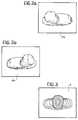
- Each television camera 3takes an elementary image 4a, 4b at a specific moment, as shown in Figures 2a and 2b respectively.
- the two elementary images 4a and 4b obtained simultaneously by the two television cameras 3are processed by a processing unit 5 which combines them to derive a single stereoscopic image 4, shown schematically in Figure 3 by a group of contour lines forming an altimetric map of the body B.
- the processing carried out by the unit 5is such as to obtain a real world correspondence between the projections of the points of each elementary image to enable information relating to the disparity, namely, the distance between different positions of a single point on the two corresponding elementary images 4a and 4b, to be deduced.
- the models of altimetric maps already stored in the processing unit for the purpose of comparisonmay be based on a single moment in the traversal of the gap by the body B, thus being of the static type, and/or they may each be constituted by a plurality of altimetric maps of a single body corresponding to different moments in the traversal of the gap and may therefore be of the dynamic type.
- a device 7 according to the inventionuses the so-called "structured light” technique which utilises particular characteristics of light to obtain information relating to the geometry of a scene.
- the device 7includes a single television camera 4 and a monochromatic light source 9 constituted, for example, by a solid state laser with an associated optic, which projects a plane of light coincident with the imaginary surface defining the gap.
- a monochromatic light source 9constituted, for example, by a solid state laser with an associated optic, which projects a plane of light coincident with the imaginary surface defining the gap.
- the television camera 4is preferably positioned with its optical axis incident on the plane of light emitted by the source 9 and so that the entirety of the gap to be checked is covered to enable the detection of all parts of the scene illuminated by the intersection with the plane of light.
- the instantaneous two-dimensional image L of part of the contour of a body B (see Figure 8) transversing the surface constituting the gap, and defined by the plane of light,is composed of a plurality of points, each of which identifies a line of view in the three-dimensional space, which line extends from the respective point in the space to its projection on the image plane passing through the focus of the television camera 4.
- the three-dimensional position of each point on the luminous line Lmay then be obtained from a calculation of the position of the intersection of the line of view with the plane of light, the position of the plane of light being known as it is defined by the position of the source 9, and eventually determinable by direct measurement, as is the spatial position of the television camera 4 and its focal axis.
- the television camera 4may, to advantage, be provided with an optical filter set to the frequency of the monochromatic light source.
- the altimetric map obtained for each body B passing through the gapmay be coded as illustrated in Figure 6 by means of a band which represents the various zones of its profile at different heights given by various shades of grey.
- Each instantaneous altimetric map, and/or its evolution over time during the traversal of the gapcan then be compared with static or dynamic models of altimetric maps of other bodies, that is, based on a single altimetric map or on a plurality of altimetric maps relating to successive moments, similarly coded and already stored in the processing unit 5 in order to recognise those of the bodies B passing through the gap that are to be counted. In this way it is possible, for example, to discriminate between people and luggage passing through the doorway of a transport means. It is also possible to recognise the contemporaneous presence of several people in the same scene.
- the movement of the body through the gapcan be reconstructed to enable the direction and sense of its movement to be deduced with the consequent evaluation of whether it is entering or exiting one of the areas adjacent the gap and the activation of a counting procedure provided by the system.
Landscapes
- Physics & Mathematics (AREA)
- General Physics & Mathematics (AREA)
- Image Analysis (AREA)
- Radar Systems Or Details Thereof (AREA)
Abstract
Description
The present invention concerns a method for automaticallydetecting and counting bodies passing through a gap. In thefollowing description and the accompanying claims, the termgap is to be understood as an imaginary surface, or a linearprojection thereof, separating two adjacent areas. It can bea physical gap such as a doorway or gateway, or a logical gapsuch as a virtual flat surface perpendicular to the floor andwalls of a passage which can be visualised, for example, bymeans of a line along an imaginary communication plane, whichmay be a floor or a step or ramp, or a rotary mat or conveyorbelt, and in general, anything which can support a flow ofbodies in one or more directions in both senses of movement.
The detection of bodies passing through a gap has varioususes. It is particularly applicable when the access of peopleor things to specific areas must be controlled. For example,in the case of people, it may be necessary to control theiraccess to public transport means, such as the underground, orto public buildings or areas such as stadia or meeting places,or into shops or various public places.
One practical application may be, for example, to count thenumber of passengers getting on or off an urban service bus ateach stop in order continuously to check the total number ofpassengers on the bus. In this way it is possible to avoidexceeding the maximum capacity of the bus, for example, bypreventing further passengers getting on a bus which isalready full. In addition, auxiliary procedures may be activated when the maximum capacity is reached, such asinforming a service centre which can put additional buses inservice to meet the public demand. Further subsidiaryactivities may result from the knowledge of the passengerdata, such as statistical analyses based on the flow ofpassengers, or the derivation of information on possibledeception by the passengers.
Currently, the automatic control of bodies passing throughgaps is achieved with the use of various techniques, such asoptical transmission and/or reflection barriers, for example,using light or infra-red radiation, or physical barriers suchas turnstiles, pressure-sensitive platforms, or movementdetectors based on microwaves, passive infrared radiation orultrasound.
It must, however, be borne in mind that there are manypractical applications in which the use of physical barriersis not acceptable for safety reasons and/or in terms ofpracticality of use.
Furthermore, all the known systems have a number oflimitations which make them unable to discriminate betweenobjects and people, between objects and people that are veryclose together, or between objects and people moving inopposite directions or not perpendicular to the imaginary lineof the gap. In addition, the known systems use sensors whichmay easily be tricked by objects or people moving at a steadyspeed.
An object of the invention is to provide a method forautomatically detecting and counting bodies passing through agap, which is simple and reliable and which enables thecontemporaneous discrimination between their direction andsense of movement in order to check the flow into or out of atleast one of the areas adjacent the gap.
This object is achieved by virtue of the fact that the methodcomprises the steps of:
- monitoring the gap with means for generating imagesignals in order to obtain a succession of images of each bodypassing through the gap, each image corresponding to aspecific moment in time;
- processing these images to obtain an altimetric map ofeach body passing through the gap for each moment considered;
- comparing at least one altimetric map obtained with atleast one model altimetric map stored in a processing unit;and
- depending on the result of the said comparison,activating a counting procedure.
By virtue of these characteristics, the method according tothe invention enables bodies of different shapes to bediscriminated between with a high degree of reliability, andthe selection of solely a particular type of body forcounting, for example, people only. In addition, the quantityof information that can be obtained by the method of theinvention, which is significantly more than that which can bederived by the known techniques, enables more reliable androbust counting to be effected, overcoming the limitationswhich usually affect known systems, and thus providing greater adaptability to different working conditions and, therefore,greater generality of application.
It is therefore possible, with the invention, to discriminatebetween objects and people even when they are very closetogether, between objects and people moving in differentdirections or generally not perpendicular to the imaginaryline of the gap, between objects and people moving at a steadyspeed or otherwise behaving in a way which could easilyconfuse the sensors used in known systems.
In particular, the term altimetric map is to be understood asany representation of the altimetric, or elevational,distortions caused by the presence of a body. One such map isobtained from the altimetric analysis of the body itselfutilising known automatic methods which enable characteristicsof the shape of the body to be described in a form which iseasily comparable with similar maps of other bodies. If thisanalysis is conducted in correspondence with a gap, it ispossible to distinguish between the bodies passing through itand, in the present case, to count just those which satisfypredetermined shape characteristics. Typically, in order todistinguish a person from other, differently-shaped bodies,one starts with the assumption that a person has a head on topof a generally cylindrical trunk, conferring a characteristicaltimetric profile thereon.
Naturally, a data processing system can be programmed in aknown way to conduct an altimetric analysis of bodies with theaim of recognising the characteristic shape of people or otherkinds of objects under consideration. Programming may be by means of conventional algorithmic approaches, the altimetriccharacteristics of the bodies to be recognised then beingprogrammed into the processing system, or by means ofstatistical learning techniques like, for example, neuralnetworks. In addition, a data processing system can bedeveloped that is capable of evaluating the space-timeevolution of the position of the bodies under consideration inorder to deduce the dynamics of their movements, inparticular, the direction and sense thereof.
A model of altimetric map of a body stored in the processingunit and utilisable for comparison with other altimetric mapsobtained for bodies passing through the gap may be of thestatic type and thus formed on the basis of a singlealtimetric map referring to one moment in the traversal of thegap by a body, or it may be of the dynamic type and thusformed on the basis of a plurality of altimetric maps relatingto a single body, each corresponding to a different moment ingap traversal.
A further subject of the invention is a device forautomatically detecting and counting bodies passing through agap, characterised in that it comprises:
- means for generating image signals relating to a gap;
- a processing unit connected to the image-signal-generatormeans for processing images arising therefrom inorder to obtain altimetric maps of each body passing throughthe gap for successive moments, the processing unit also beingcapable of comparing at least one altimetric map obtained withat least one model altimetric map stored therein in order to activate at least one counting process depending on the resultof the comparison.
Further characteristics and advantages of the presentinvention will become clearer from the following detaileddescription, given purely by way of non-limitative example andwith reference to the accompanying drawings, in which:
- Figure 1 is a schematic perspective view showing a firstembodiment of a device according to the invention;
- Figures 2a, 2b and 3 are, respectively, schematicillustrations of two views obtained by means of the device ofFigure 1, and a stereoscopic view derived therefrom;
- Figure 4 is a view similar to Figure 1 of a furtherembodiment of a device according to the invention; and
- Figures 5 to 9 are views illustrating schematically themodes of operation of the device of Figure 4.
With reference to Figures 1 to 3, the reference numeral 1generally indicates a device for automatically detecting andcounting bodies passing through a gap. In particular, thedevice 1 is intended for obtaining the altimetric map of abody B which passes close to it, in this particular case belowit, following to the composition of its stereoscopic image.
More specifically, the device 1 includes a pair of televisioncameras 3, conveniently of the low-resolution type, spacedfrom each other and preferably on the vertical of the gap tobe checked. This gap is defined by an imaginary surface whichis, for example, flat and vertical, capable of being traversedby moving bodies B, and defined at the base by a threshold line A which constitutes the projection on the ground of theimaginary surface.
Each television camera 3 takes anelementary image 4a, 4b at aspecific moment, as shown in Figures 2a and 2b respectively.The twoelementary images 4a and 4b obtained simultaneously bythe two television cameras 3 are processed by aprocessingunit 5 which combines them to derive a singlestereoscopicimage 4, shown schematically in Figure 3 by a group of contourlines forming an altimetric map of the body B. The processingcarried out by theunit 5 is such as to obtain a real worldcorrespondence between the projections of the points of eachelementary image to enable information relating to thedisparity, namely, the distance between different positions ofa single point on the two correspondingelementary images 4aand 4b, to be deduced. With theelementary images 4a and 4btaken simultaneously by each television camera 3 and thearrangement of the television cameras 3 with respect to thegap all being known, the three-dimensional spatial positionsof all the points observed can be determined unequivocally.It is therefore possible to obtain a moment-by-momentaltimetric, or elevational, map of the gap and the bodies Bpassing through it. As a result of a comparison of thisaltimetric map and its evolution over time with models knownto theprocessing unit 5, it is easy to deduce whether a bodyB which passes through the gap satisfies predeterminedconditions, for example, the fact that it has a head on top ofa trunk in the case of a person, and is therefore to becounted. As discussed above, the models of altimetric mapsalready stored in the processing unit for the purpose ofcomparison may be based on a single moment in the traversal of the gap by the body B, thus being of the static type, and/orthey may each be constituted by a plurality of altimetric mapsof a single body corresponding to different moments in thetraversal of the gap and may therefore be of the dynamic type.
From the mutual comparison of altimetric maps corresponding toa single body obtained at successive moments, it is alsopossible to deduce the direction and sense of movement of eachbody B. In this way, it is possible to count a body B in adifferent way or to decide whether to count it or notdepending on its sense of movement with respect to thethreshold line A.
According to a further embodiment, and with reference toFigures 4 to 9, adevice 7 according to the invention uses theso-called "structured light" technique which utilisesparticular characteristics of light to obtain informationrelating to the geometry of a scene.
In this case, thedevice 7 includes asingle television camera 4 and a monochromatic light source 9 constituted, for example,by a solid state laser with an associated optic, whichprojects a plane of light coincident with the imaginarysurface defining the gap. In this way, each body B passingthrough the gap breaks the plane of light and, as a result ofits intersection therewith, causes luminous contour lines L tobe generated on the edges of the body B, each of which, beingilluminated by the plane of light, corresponds to aninstantaneous, two-dimensional image of part of the contour ofa section through the body B (see Figures 4, 5 and 7).
Thetelevision camera 4 is preferably positioned with itsoptical axis incident on the plane of light emitted by thesource 9 and so that the entirety of the gap to be checked iscovered to enable the detection of all parts of the sceneilluminated by the intersection with the plane of light. Theinstantaneous two-dimensional image L of part of the contourof a body B (see Figure 8) transversing the surfaceconstituting the gap, and defined by the plane of light, iscomposed of a plurality of points, each of which identifies aline of view in the three-dimensional space, which lineextends from the respective point in the space to itsprojection on the image plane passing through the focus of thetelevision camera 4. The three-dimensional position of eachpoint on the luminous line L may then be obtained from acalculation of the position of the intersection of the line ofview with the plane of light, the position of the plane oflight being known as it is defined by the position of thesource 9, and eventually determinable by direct measurement,as is the spatial position of thetelevision camera 4 and itsfocal axis.
Only those surfaces of a body B that are substantiallyparallel to the plane of light are of uncertain detection bythis technique, but this disadvantage can be overcome by thechoice of an appropriate arrangement of thetelevision camera 4 with respect to the light source 9.
Thetelevision camera 4 may, to advantage, be provided with anoptical filter set to the frequency of the monochromatic lightsource.
From an analysis of the group of luminous lines Lo, L1, ..., LN(see Figure 9) generated at successive moments t0, t1, ..., tNby the intersection of the plane of light projected by thesource 9 with the profile of a body B traversing it,sufficient information about the shape of the surface of thebody itself can be obtained to form the altimetric map of thebody B.
The altimetric map obtained for each body B passing throughthe gap, which corresponds to the shape of the body itself ata specific moment, may be coded as illustrated in Figure 6 bymeans of a band which represents the various zones of itsprofile at different heights given by various shades of grey.Each instantaneous altimetric map, and/or its evolution overtime during the traversal of the gap, can then be comparedwith static or dynamic models of altimetric maps of otherbodies, that is, based on a single altimetric map or on aplurality of altimetric maps relating to successive moments,similarly coded and already stored in theprocessing unit 5 inorder to recognise those of the bodies B passing through thegap that are to be counted. In this way it is possible, forexample, to discriminate between people and luggage passingthrough the doorway of a transport means. It is also possibleto recognise the contemporaneous presence of several people inthe same scene.
By considering the variation of the altimetric map of a bodyover time, the movement of the body through the gap can bereconstructed to enable the direction and sense of itsmovement to be deduced with the consequent evaluation ofwhether it is entering or exiting one of the areas adjacent the gap and the activation of a counting procedure provided bythe system.
Claims (14)
- A method for automatically detecting and counting bodiespassing through a gap, characterised that in it comprises thesteps of:monitoring the gap (A) with means for generating imagesignals (3; 4, 9) to obtain a succession of images (4a, 4b;L0, L1, ...,LN) of each body (B) passing through the gap (A),each image (4a, 4b; L0, L1, ..., LN) corresponding to aspecific moment in time;processing these images (4a, 4b; L0, L1, ..., LN) toobtain an altimetric map of each body (B) passing through thegap (A) for each moment considered;comparing at least one altimetric map obtained with atleast one models of altimetric map stored in the processingunit (5); andactivating a counting procedure depending on the resultof the said comparison.
- A method according to Claim 1, characterised in that themodels of altimetric maps include at least one altimetric mapof a reference body corresponding to one moment in thetraversal of the gap (A) by the respective body, and/or atleast a plurality of altimetric maps of a reference bodycorresponding to different moments in the traversal of the gap(A) by that body.
- A method according to Claim 1 or Claim 2, characterised inthat the altimetric maps of a body (B) obtained at differentmoments are compared with each other to determine the dynamicsof the movement of the body (B) through the gap (A).
- A method according to claim 3, characterised in that thecounting procedure is activated in different ways depending onthe dynamics of movement of each body (B) passing through thegap (A).
- A method according to any of Claims 1 to 4, characterisedin that the images (4a, 4b) obtained by the means forgenerating the image signals (3) are processed to obtain astereoscopic image (4) of each body (B) passing through thegap (A).
- A method according to any of Claims 1 to 4, characterisedin that the means for generating the image signals (4, 9) arecapable of obtaining two-dimensional images (L0, L1, ..., LN)containing altimetric information by the application of thestructured light technique.
- A device for automatically detecting and counting bodiespassing through a gap, characterised in that it comprises:means for generating image signals (3; 4, 9) associatedwith a gap (A); and
a processing unit (5) connected to the image-signal-generatormeans (3; 4, 9) for processing images (4a, 4b; L0, L1, ..., LN)arising therefrom in order to obtain altimetric maps of eachbody (B) passing through the gap (A) for successive moments,the processing unit (5) also being capable of comparing atleast one altimetric map obtained with at least one modelaltimetric map stored therein in order to activate at leastone counting procedure depending on the result of thecomparison. - A device according to Claim 7, characterised in that theprocessing unit (5) is capable of storing models of altimetricmaps including at least one altimetric map of a reference bodycorresponding to one moment in the traversal of the gap (A) bythat body, and/or at least a plurality of altimetric maps of areference body corresponding to different moments in thetraversal of the gap (A) by that body.
- A device according to Claim 7 or Claim 8, characterised inthat the image-signal-generator means comprise two televisioncameras (3) disposed with their respective focal axes spacedfrom each other, and in that the processing unit (5) iscapable of handling a pair of images (4a, 4b) acquired by thesaid television cameras (3) at a single moment to formtherefrom a stereoscopic image (4) of each body (B) passingthrough the gap (A) at that moment, and to obtain anassociated altimetric map from this stereoscopic image (4).
- A device according to Claim 9, characterised in that thefocal axes of the said television cameras (3) lie in animaginary surface defining the gap (A).
- A device according to Claim 7 or Claim 8, characterised inthat the image-signal-generator means comprise a light source(9) capable of projecting a plane of light coincident with animaginary surface defining the gap (A), and a televisioncamera (4) disposed with its focal axis incident on thissurface, and in that the processing unit (5) is capable ofhandling a plurality of two-dimensional images (L0, L1, ...,LN) acquired by the television camera (4), each corresponding to a different moment, in order to obtain an altimetric map ofeach body which passes through the gap (A).
- A device according to Claim 11, characterised in that thelight source (9) is a monochromatic light source, preferably asolid state laser.
- A device according to Claim 12, characterised in that thetelevision camera (4) has an optic provided with a filter setto the frequency of the light emitted by the light source (9).
- A device according to Claim 10 or Claim 11, characterisedin that the processing unit (5) is capable of comparingaltimetric maps relating to successive moments for each body(B) passing through the gap (A), and of determining thedirection and sense of movement of each body (B) through thegap (A).
Applications Claiming Priority (2)
| Application Number | Priority Date | Filing Date | Title |
|---|---|---|---|
| ITTO960984IT1289712B1 (en) | 1996-12-04 | 1996-12-04 | PROCEDURE AND DEVICE FOR THE DETECTION AND AUTOMATIC COUNTING OF BODIES CROSSING A GATE |
| ITTO960984 | 1996-12-04 |
Publications (2)
| Publication Number | Publication Date |
|---|---|
| EP0847030A2true EP0847030A2 (en) | 1998-06-10 |
| EP0847030A3 EP0847030A3 (en) | 1999-12-01 |
Family
ID=11415077
Family Applications (1)
| Application Number | Title | Priority Date | Filing Date |
|---|---|---|---|
| EP97121056AWithdrawnEP0847030A3 (en) | 1996-12-04 | 1997-12-01 | A method and device for automatically detecting and counting bodies passing through a gap |
Country Status (2)
| Country | Link |
|---|---|
| EP (1) | EP0847030A3 (en) |
| IT (1) | IT1289712B1 (en) |
Cited By (13)
| Publication number | Priority date | Publication date | Assignee | Title |
|---|---|---|---|---|
| FR2800895A1 (en)* | 1999-11-09 | 2001-05-11 | Renault Vehicules Ind | BUS PASSENGER COUNTING SYSTEM AND METHOD |
| EP1306815A1 (en)* | 2001-10-25 | 2003-05-02 | SkiData AG | Access control device |
| WO2003088157A1 (en)* | 2002-04-08 | 2003-10-23 | Newton Security Inc. | Tailgating and reverse entry detection, alarm, recording and prevention using machine vision |
| US7397929B2 (en) | 2002-09-05 | 2008-07-08 | Cognex Technology And Investment Corporation | Method and apparatus for monitoring a passageway using 3D images |
| US7400744B2 (en) | 2002-09-05 | 2008-07-15 | Cognex Technology And Investment Corporation | Stereo door sensor |
| US7623674B2 (en) | 2003-11-05 | 2009-11-24 | Cognex Technology And Investment Corporation | Method and system for enhanced portal security through stereoscopy |
| US7680323B1 (en) | 2000-04-29 | 2010-03-16 | Cognex Corporation | Method and apparatus for three-dimensional object segmentation |
| US7692684B2 (en) | 2004-09-27 | 2010-04-06 | Point Grey Research Inc. | People counting systems and methods |
| WO2010130964A1 (en)* | 2009-05-14 | 2010-11-18 | INRETS - Institut National de Recherche sur les Transports et leur Sécurité | System for counting people |
| US7920718B2 (en) | 2002-09-05 | 2011-04-05 | Cognex Corporation | Multi-zone passageway monitoring system and method |
| US8111904B2 (en) | 2005-10-07 | 2012-02-07 | Cognex Technology And Investment Corp. | Methods and apparatus for practical 3D vision system |
| US8126260B2 (en) | 2007-05-29 | 2012-02-28 | Cognex Corporation | System and method for locating a three-dimensional object using machine vision |
| US8326084B1 (en) | 2003-11-05 | 2012-12-04 | Cognex Technology And Investment Corporation | System and method of auto-exposure control for image acquisition hardware using three dimensional information |
Family Cites Families (4)
| Publication number | Priority date | Publication date | Assignee | Title |
|---|---|---|---|---|
| NL8702738A (en)* | 1987-11-17 | 1989-06-16 | Heineken Technische Beheer Bv | METHOD AND APPARATUS FOR COUNTING OBJECTS OBTAINED ON A TRANSPORTATION TRACK |
| US5305390A (en)* | 1991-01-11 | 1994-04-19 | Datatec Industries Inc. | Person and object recognition system |
| DE4411448C5 (en)* | 1994-03-31 | 2009-05-14 | Sick Ag | Method and device for controlling a given monitoring area |
| DE19516662A1 (en)* | 1995-05-05 | 1996-11-14 | Fraunhofer Ges Forschung | Identification method for three-dimensional objects |
- 1996
- 1996-12-04ITITTO960984patent/IT1289712B1/enactiveIP Right Grant
- 1997
- 1997-12-01EPEP97121056Apatent/EP0847030A3/ennot_activeWithdrawn
Cited By (16)
| Publication number | Priority date | Publication date | Assignee | Title |
|---|---|---|---|---|
| FR2800895A1 (en)* | 1999-11-09 | 2001-05-11 | Renault Vehicules Ind | BUS PASSENGER COUNTING SYSTEM AND METHOD |
| EP1100050A1 (en)* | 1999-11-09 | 2001-05-16 | Renault V.I. | System and method of counting passengers for buses |
| US7680323B1 (en) | 2000-04-29 | 2010-03-16 | Cognex Corporation | Method and apparatus for three-dimensional object segmentation |
| EP1306815A1 (en)* | 2001-10-25 | 2003-05-02 | SkiData AG | Access control device |
| US7382895B2 (en) | 2002-04-08 | 2008-06-03 | Newton Security, Inc. | Tailgating and reverse entry detection, alarm, recording and prevention using machine vision |
| WO2003088157A1 (en)* | 2002-04-08 | 2003-10-23 | Newton Security Inc. | Tailgating and reverse entry detection, alarm, recording and prevention using machine vision |
| US7397929B2 (en) | 2002-09-05 | 2008-07-08 | Cognex Technology And Investment Corporation | Method and apparatus for monitoring a passageway using 3D images |
| US7400744B2 (en) | 2002-09-05 | 2008-07-15 | Cognex Technology And Investment Corporation | Stereo door sensor |
| US7920718B2 (en) | 2002-09-05 | 2011-04-05 | Cognex Corporation | Multi-zone passageway monitoring system and method |
| US7623674B2 (en) | 2003-11-05 | 2009-11-24 | Cognex Technology And Investment Corporation | Method and system for enhanced portal security through stereoscopy |
| US8326084B1 (en) | 2003-11-05 | 2012-12-04 | Cognex Technology And Investment Corporation | System and method of auto-exposure control for image acquisition hardware using three dimensional information |
| US7692684B2 (en) | 2004-09-27 | 2010-04-06 | Point Grey Research Inc. | People counting systems and methods |
| US8111904B2 (en) | 2005-10-07 | 2012-02-07 | Cognex Technology And Investment Corp. | Methods and apparatus for practical 3D vision system |
| US8126260B2 (en) | 2007-05-29 | 2012-02-28 | Cognex Corporation | System and method for locating a three-dimensional object using machine vision |
| WO2010130964A1 (en)* | 2009-05-14 | 2010-11-18 | INRETS - Institut National de Recherche sur les Transports et leur Sécurité | System for counting people |
| FR2945652A1 (en)* | 2009-05-14 | 2010-11-19 | Inrets Inst Nat De Rech Sur Le | SYSTEM FOR COUNTING PEOPLE. |
Also Published As
| Publication number | Publication date |
|---|---|
| IT1289712B1 (en) | 1998-10-16 |
| ITTO960984A1 (en) | 1998-06-04 |
| EP0847030A3 (en) | 1999-12-01 |
Similar Documents
| Publication | Publication Date | Title |
|---|---|---|
| EP0847030A2 (en) | A method and device for automatically detecting and counting bodies passing through a gap | |
| US7382895B2 (en) | Tailgating and reverse entry detection, alarm, recording and prevention using machine vision | |
| US5519784A (en) | Apparatus for classifying movement of objects along a passage by type and direction employing time domain patterns | |
| CN1315715C (en) | Camera for monitoring escalator and mobile footway | |
| US6430303B1 (en) | Image processing apparatus | |
| CN106144862A (en) | Passenger based on depth transducer for passenger traffic gate control senses | |
| CN106144861A (en) | Passenger based on the depth transducer sensing controlled for passenger traffic | |
| CN106144816A (en) | Occupant detection based on depth transducer | |
| CN106144795A (en) | By identifying that user operation controls for passenger traffic and the system and method for safety | |
| JP2017519289A (en) | System and method for tracking vehicles in parking structures and intersections | |
| CA2361486A1 (en) | Object recognition and tracking system | |
| EP2546807B1 (en) | Traffic monitoring device | |
| CN107662867A (en) | The step roller monitoring of passenger conveyor and maintenance operation monitored by personnel | |
| EP3635614A1 (en) | Method and system for object detection and classification | |
| US6600509B1 (en) | Detection system | |
| JP2020518046A (en) | An optical system that monitors the movement of a person through a passage | |
| CN109633684A (en) | For the method, apparatus of classification, machine learning system and machine readable storage medium | |
| JP3664784B2 (en) | Wide area monitoring device | |
| JP4208400B2 (en) | Automatic door opening and closing control method | |
| KR20050003664A (en) | A Vehicle base photographing device and a control system of an in-out vehicle using thereof | |
| CN109983518A (en) | For detecting the method and system for the protrusion object being located in parking lot | |
| CH700703B1 (en) | Means for passage control and traffic separation. | |
| EP3526727A2 (en) | Stereometric object flow interaction | |
| WO1996013023A1 (en) | A device for the identification of vehicles at a control station | |
| JP6016411B2 (en) | Intruder detection system, intruder detection method, and intruder detection program |
Legal Events
| Date | Code | Title | Description |
|---|---|---|---|
| PUAI | Public reference made under article 153(3) epc to a published international application that has entered the european phase | Free format text:ORIGINAL CODE: 0009012 | |
| AK | Designated contracting states | Kind code of ref document:A2 Designated state(s):DE ES FR GB | |
| AX | Request for extension of the european patent | Free format text:AL;LT;LV;MK;RO;SI | |
| PUAL | Search report despatched | Free format text:ORIGINAL CODE: 0009013 | |
| AK | Designated contracting states | Kind code of ref document:A3 Designated state(s):AT BE CH DE DK ES FI FR GB GR IE IT LI LU MC NL PT SE | |
| AX | Request for extension of the european patent | Free format text:AL;LT;LV;MK;RO;SI | |
| 17P | Request for examination filed | Effective date:20000531 | |
| AKX | Designation fees paid | Free format text:DE ES FR GB | |
| 17Q | First examination report despatched | Effective date:20020807 | |
| STAA | Information on the status of an ep patent application or granted ep patent | Free format text:STATUS: THE APPLICATION IS DEEMED TO BE WITHDRAWN | |
| 18D | Application deemed to be withdrawn | Effective date:20030218 |