EP0846435B1 - A cooking pot for food - Google Patents
A cooking pot for foodDownload PDFInfo
- Publication number
- EP0846435B1 EP0846435B1EP19960830635EP96830635AEP0846435B1EP 0846435 B1EP0846435 B1EP 0846435B1EP 19960830635EP19960830635EP 19960830635EP 96830635 AEP96830635 AEP 96830635AEP 0846435 B1EP0846435 B1EP 0846435B1
- Authority
- EP
- European Patent Office
- Prior art keywords
- holding body
- base wall
- heat
- auxiliary
- side wall
- Prior art date
- Legal status (The legal status is an assumption and is not a legal conclusion. Google has not performed a legal analysis and makes no representation as to the accuracy of the status listed.)
- Expired - Lifetime
Links
- 235000013305foodNutrition0.000titleclaimsdescription14
- 238000010411cookingMethods0.000titleclaimsdescription12
- 239000011796hollow space materialSubstances0.000claimsdescription14
- 239000000463materialSubstances0.000claimsdescription10
- 239000004020conductorSubstances0.000claimsdescription3
- 238000003466weldingMethods0.000claimsdescription2
- 230000007797corrosionEffects0.000description5
- 238000005260corrosionMethods0.000description5
- 229910000831SteelInorganic materials0.000description4
- 239000004411aluminiumSubstances0.000description4
- 229910052782aluminiumInorganic materials0.000description4
- XAGFODPZIPBFFR-UHFFFAOYSA-NaluminiumChemical compound[Al]XAGFODPZIPBFFR-UHFFFAOYSA-N0.000description4
- 229910001220stainless steelInorganic materials0.000description4
- 239000010935stainless steelSubstances0.000description4
- 239000010959steelSubstances0.000description4
- 101100298222Caenorhabditis elegans pot-1 geneProteins0.000description3
- 238000009413insulationMethods0.000description3
- 230000001681protective effectEffects0.000description3
- 238000004519manufacturing processMethods0.000description2
- 230000009471actionEffects0.000description1
- 230000005540biological transmissionEffects0.000description1
- 239000002775capsuleSubstances0.000description1
- 239000003795chemical substances by applicationSubstances0.000description1
- 230000003247decreasing effectEffects0.000description1
- 230000008642heat stressEffects0.000description1
- 238000010438heat treatmentMethods0.000description1
- 230000006872improvementEffects0.000description1
- 230000002401inhibitory effectEffects0.000description1
- 230000000670limiting effectEffects0.000description1
- 239000007769metal materialSubstances0.000description1
- 230000004048modificationEffects0.000description1
- 238000012986modificationMethods0.000description1
- 230000008092positive effectEffects0.000description1
- 238000000926separation methodMethods0.000description1
- 238000007493shaping processMethods0.000description1
- 230000035939shockEffects0.000description1
- 230000007480spreadingEffects0.000description1
- 230000035882stressEffects0.000description1
- 230000008646thermal stressEffects0.000description1
Images


Classifications
- A—HUMAN NECESSITIES
- A47—FURNITURE; DOMESTIC ARTICLES OR APPLIANCES; COFFEE MILLS; SPICE MILLS; SUCTION CLEANERS IN GENERAL
- A47J—KITCHEN EQUIPMENT; COFFEE MILLS; SPICE MILLS; APPARATUS FOR MAKING BEVERAGES
- A47J27/00—Cooking-vessels
- A47J27/002—Construction of cooking-vessels; Methods or processes of manufacturing specially adapted for cooking-vessels
Definitions
- the prevent inventionrelates to a saucepan or pot for cooking food.
- pots consisting of a mere steel containerhave been gradually replaced by pots provided with a capsule-like bottom.
- said potsconsist of a holding body usually made of a stainless steel material, a layer of a highly heat-conductive material, generally aluminium, being associated with the base wall of said body, said layer being in turn coupled to a protective steel cover.
- the highly heat-conductive material layeris encapsulated between said base wall and cover layer.
- Steel pots provided with a capsule like bottomhave advantageously enabled achievement of good results in terms of efficiency in transmitting heat from the heating surface to the pot bottom and reaching an even heat spreading at the base wall of the holding body containing the food to be cooked.
- pots presently available on the marketare not yet capable of inhibiting heat loss in an efficient manner, in particular at the side wall of the pot itself that, due to its surface extension, undoubtedly represents an area of high heat loss.
- a saucepanis known according to the preamble of claim 1, presenting an inner container having a cilindrical side wall and a bottom wall closing one end of the side wall.
- An outer containerhaving a cilindrical side wall and a bottom too, contains and is joined to the inner container so as to define a tubular hollow space between the two bodies.
- the saucepanalso has a heat diffusing layer interposed between and fixed to the bottom wall of the inner container and to the bottom wall of the outer container.
- the external side wallpresents an annular recess in order to allow the connection with a thermal insulating plate to be placed under the saucepan.
- the aim of the inventionreferring particularly to pots having a capsule-like bottom, is to provide a pot which is of strong structure, great reliability, substantially resistant to external agent attacks and devoid of unattractive discontinuites at the junction area between the pot bottom and base wall.
- a saucepan or pot for cooking food in accordance with the present inventionhas been generally identified by reference numeral 1.
- Pot 1is comprised of a main holding body 2 of metal material , preferably stainless steel , having a base wall 3 and a side wall 4 emerging from a perimetric edge of said base wall to define a containing housing 5 in which food to be submitted to cooking is to be placed.
- metal materialpreferably stainless steel
- pot 1further comprises an auxiliary holding body 6 which is also provided with a respective base wall 7 and a respective side wall 8 emerging from said base wall.
- the auxiliary body 6the shape of which preferably matches that of the main body, is externally joined to said main body in a fixed manner. It is to note that from the point of view of their conformation, said bodies 2 and 6 can exhibit a circular (see Fig. 1) or polygonal (see Fig. 4) cross section.
- a heat-diffusing layer 9 of a material having a high heat conductivityOperatively interposed between the base wall 3 of the main body 2 and the base wall 7 of the auxiliary body 6, there is a heat-diffusing layer 9 of a material having a high heat conductivity.
- the heat-diffusing layer 9is made of aluminium and is fixedly joined both to the base wall 3 and the base wall 7. From a production point of view, the heat-diffusing layer 9 is associated with the main body and the auxiliary body by a combined pressure-heat action. Practically, shaping of bodies 2 and 6 as well as of the heat-diffusing layer 9 takes place by a single hot forming operation, and the base walls 3 and 7 are fixedly joined to the respective opposite faces of the heat-diffusing layer 9.
- the auxiliary holding body 6comprises an annular connecting band 6a between its base wall 7 and side wall 8, substantially extending at the heat-diffusing layer 9.
- the annular connecting band 6a toois fixedly connected to a corresponding outer perimetric band 10 of the heat-diffusing layer 9.
- the above solutionenables conveying of heat from the cookers to the heat-diffusing layer 9, and therefore to the main wall 3 of the main body 2, to be maximized.
- main body 2 and auxiliary body 6are also fixedly interconnected at an upper rim 11, 12, by welding for example.
- pot 1also comprises a tubular insulating hollow space 13 operatively defined between the side wall 4 of the main holding body 2 and the side wall 8 of the auxiliary holding body 6.
- the tubular hollow space 13is tightly sealed up and can contain air or, as an alternative solution, be substantially under vacuum or contain a very rarefied gas.
- the insulating capability of the tubular hollow spaceis advantageously maximized and, on the other hand, the possibility that too high pressures may be generated in the gas possibly present in said hollow space, as the temperature rises, is inhibited.
- tubular hollow space 13has a minimum radial bulkiness at the annular connecting band 9 and the upper rims 11 and 12 and a maximum radial bulkiness at the side walls 4 and 8 and, more specifically, at a lower area 4a, 8a of said side walls.
- the inventionachieves important advantages.
- the hollow space 13provides an insulation of the side wall 4 which is greatly efficient and leads to a sure improvement in the cooking uniformity of foods and in saving energy.
- said hollow spacehas a minimum radial bulkiness at the area (annular connecting band 6a) where heat needs to be efficiently transferred and a maximum radial bulkiness at the area (side wall 4) where an efficient heat insulation is required.
- connection between the main body and auxiliary bodyhas been exclusively provided at the upper rims 11 and 12 and at the heat-diffusing layer 9, an excellent structural strength and reliability is ensured and in addition the pot of the invention can be produced at high production rates.
- the pot in referenceis also particularly appreciable from an aesthetic point of view since all discontinuities typical in particular of the traditional pots provided with a capsule-like bottom have been eliminated.
Landscapes
- Engineering & Computer Science (AREA)
- Manufacturing & Machinery (AREA)
- Food Science & Technology (AREA)
- Cookers (AREA)
- Thermally Insulated Containers For Foods (AREA)
Description
- The prevent invention relates to a saucepan or pot forcooking food.
- It is known that pots used for cooking food haveundergone plenty of modifications over time tending toimprove the energetic efficiency of same and reachuniformity in cooking.
- In particular, pots consisting of a mere steel containerhave been gradually replaced by pots provided with acapsule-like bottom. More specifically; said potsconsist of a holding body usually made of a stainlesssteel material, a layer of a highly heat-conductivematerial, generally aluminium, being associated with thebase wall of said body, said layer being in turncoupled to a protective steel cover. In this way thehighly heat-conductive material layer is encapsulatedbetween said base wall and cover layer.
- Steel pots provided with a capsule like bottom haveadvantageously enabled achievement of good results interms of efficiency in transmitting heat from theheating surface to the pot bottom and reaching an evenheat spreading at the base wall of the holding bodycontaining the food to be cooked.
- In spite of the technical solutions briefly describedabove, it is to point out that pots presently availableon the market are not yet capable of inhibiting heatloss in an efficient manner, in particular at the sidewall of the pot itself that, due to its surfaceextension, undoubtedly represents an area of high heatloss.
- For the above reason, presently available pots have arestricted thermal efficiency in that most of the heatsent to them is irreparably lost.
- In addition, when foods are submitted to cooking it isalways under a condition of decreasing temperature awayfrom the bottom wall, which therefore will bring about aclear unevenness in treatment.
- Referring particularly to pots provided with a capsule-likebottom, it is also to point out that, since anouter protective cover of stainless steel material(preventing corrosion and other similar phenomena) needsto be associated with the aluminium layer, a wellapparent discontinuity will arise at the interconnectingarea between the side wall of the protective cover andthe base wall of the holding body. This discontinuity,on the other hand, takes place exactly at an areaparticularly exposed to heat from cookers and thereforesubjected to strong thermal stresses. Said structurediscontinuity together with heat stresses sometimescauses micro-separations that are likely to triggercorrosion off, which phenomena, in the long run, mayalso involve greater damages to the pot bottom.
- Even at best, the presence of an annular junction areabetween the capsule-like bottom and the base wall of theholding body is aesthetically rather unpleasant and inany case becomes a preferential area for deposit ofhardly removable dirt.
- It is also important to note that traditional pots areusually made of materials (e.g. stainless steel ) mainlydirected to resist strong heat shocks, which materialshowever appear to be weakly resistant to the corrosionto which foods being cooked are submitted. On the otherhand, the use of corrosion-resistant materials (alloyedsteels) is not advisable because these materials areoften inappropriate to withstand the thermal andmechanical stresses to which the outer portion of a potis usually submitted.
- From document EP 0222699 a saucepan isknown according to the preamble of claim 1,presenting an inner containerhaving a cilindrical side wall and a bottom wall closing one end of the side wall.An outer container, having a cilindrical side wall and a bottom too, contains and is joinedto the inner container so as to define a tubular hollow space between the two bodies.The saucepan also has a heat diffusing layer interposed between and fixed to the bottomwall of the inner container and to the bottom wall of the outer container.The external side wall presents an annular recess in order to allow the connection witha thermal insulating plate to be placed under the saucepan.
- The aim of the invention, referringparticularly to pots having a capsule-like bottom, is toprovide a pot which is of strong structure, greatreliability, substantially resistant to external agentattacks and devoid of unattractive discontinuites at thejunction area between the pot bottom and base wall.
- The foregoing will becomemore apparent in the course of the present description andis substantially achieved by a saucepan or pot forcooking food as claimed in the appended claims.
- Further features and advantages will best be understoodfrom the detailed description of some preferred and non-exclusiveembodiments of a pot for cooking food inaccordance with the invention, taken hereinafter withreference to the accompanying drawings given by way ofnon-limiting examples, in which:
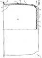
- Fig. 1 is a fragmentary sectional view of a pot forcooking food in accordance with the invention;
- Fig. 2 is an enlarged sectional view of a detail shownin Fig. 1 relating to an upper rim of the pot inquestion;
- Fig. 3 is an enlarged sectional view of another detailof Fig. 1 relating to a base area of the pot inquestion; and
- Fig. 4 is an elevational front view of an alternativeembodiment of the pot in accordance with the invention.
- With reference to the accompanying drawings, a saucepanor pot for cooking food in accordance with the presentinvention has been generally identified by referencenumeral 1.
- Pot 1 is comprised of a
main holding body 2 of metalmaterial , preferably stainless steel , having abasewall 3 and a side wall 4 emerging from a perimetric edgeof said base wall to define a containinghousing 5 in which food to be submitted to cooking is to be placed. - In an original manner, pot 1 further comprises an
auxiliary holding body 6 which is also provided with arespective base wall 7 and arespective side wall 8emerging from said base wall. Theauxiliary body 6 theshape of which preferably matches that of the main body,is externally joined to said main body in a fixedmanner. It is to note that from the point of view oftheir conformation, saidbodies - Operatively interposed between the
base wall 3 of themain body 2 and thebase wall 7 of theauxiliary body 6, there is a heat-diffusing layer 9 ofa material having a high heat conductivity. - In this case the heat-diffusing layer 9 is made ofaluminium and is fixedly joined both to the
base wall 3and thebase wall 7. From a production point of view,the heat-diffusing layer 9 is associated with the mainbody and the auxiliary body by a combined pressure-heataction. Practically, shaping ofbodies base walls - As can be viewed from the accompanying figures, the
auxiliary holding body 6 comprises an annular connectingband 6a between itsbase wall 7 andside wall 8,substantially extending at the heat-diffusing layer 9.The annular connecting band 6a too is fixedly connectedto a corresponding outerperimetric band 10 of the heat-diffusinglayer 9. - The above solution enables conveying of heat from thecookers to the heat-diffusing layer 9, and therefore tothe
main wall 3 of themain body 2, to be maximized. - It should be noted that the
main body 2 andauxiliarybody 6 are also fixedly interconnected at anupper rim - In accordance with another advantageous aspect of theinvention, it is to point out that pot 1 also comprisesa tubular insulating
hollow space 13 operatively definedbetween the side wall 4 of themain holding body 2 andtheside wall 8 of theauxiliary holding body 6. - Preferably, the tubular
hollow space 13 is tightlysealed up and can contain air or, as an alternativesolution, be substantially under vacuum or contain avery rarefied gas. - In the instance of the hollow space being substantiallyempty, on the one hand the insulating capability of thetubular hollow space is advantageously maximized and, onthe other hand, the possibility that too high pressuresmay be generated in the gas possibly present in saidhollow space, as the temperature rises, is inhibited.
- Still referring to the accompanying drawings and in moredetail, it is to note that the tubular
hollow space 13has a minimum radial bulkiness at the annular connectingband 9 and theupper rims side walls 4 and 8 and, morespecifically, at a lower area 4a, 8a of said side walls. - The invention achieves important advantages.
- First of all, due to the provision of a double holdingbody or container, an improved heat insulation of thefood being cooked is ensured. The above, together withthe presence of a capsule-like bottom with a heat-diffusinglayer made of aluminium practically enables agood heat transmission to the
base wall 3 to be achievedtogether with a good capability to retain heat withinthe containinghousing 5, by virtue of thedouble sidewall 4, 8. - In particular, the
hollow space 13 provides an insulation of the side wall4 which is greatly efficient and leads to a sureimprovement in the cooking uniformity of foods and insaving energy. - It is also to note that the particular conformation ofthe hollow space is advantageous.
- Actually said hollow space has a minimum radialbulkiness at the area (annular connecting band 6a) whereheat needs to be efficiently transferred and a maximumradial bulkiness at the area (side wall 4) where anefficient heat insulation is required.
- It is also important to note that since connectionbetween the main body and auxiliary body has beenexclusively provided at the
upper rims - It should be also recognized that the pot in referenceis also particularly appreciable from an aesthetic pointof view since all discontinuities typical in particularof the traditional pots provided with a capsule-likebottom have been eliminated.
- The absence of discontinuities also has a positiveeffect on the pot reliability because said pot does notpossess areas where dirt is likely to be deposited or corrosion may start.
Claims (6)
- A saucepan or pot for cooking food comprising:characterized by the fact that the auxiliary holdingbody (6) comprises an annular connecting band (6a)located between its base wall (7) and side wall (8),said annular connecting band being fixedly connected toa corresponding outer perimetric band (10) of a heat-diffusinglayer (9), and by the fact that the tubularhollow space (13) has a minimun radial bulkiness closeto the annular connecting band (6a) and a maximum radialbulkiness at a lower area (4a) and (8a) of the sidewalls (4) and (8).a main holding body (2) having a base wall (3) and aside wall (4) emerging from said base wall,an auxiliary holding body (6) which also has arespective base wall (7) and a respective side wall (8),said auxiliary body being externally and fixedly joinedto said main body,a heat-diffusing layer (9) of a highly heat conductivematerial operatively interposed between the base wall(3) of said main body (2) and base wall (7) of saidauxiliary body (6), anda tubular insulating hollow space (13) operativelydefined between the side wall (4) of the main holdingbody (2) and the side wall (8) of the auxiliary holdingbody (6),
- A pot according to claim 1, characterized in thatsaid heat-diffusing layer (9) is fixedly joined both tothe base wall (3) of the main holding body (2) and thebase wall (7) of the auxiliary holding body (6).
- A pot according to claim 1, characterized in thatsaid tubular hollow space (13) is tightly sealed up.
- A pot according to claim 1 or 3, characterized inthat said tubular hollow space (13) is substantiallyunder vacuum.
- A pot according to claim 1, characterized in thatsaid main holding body (2) comprises an upper rim (11)coupled by welding to a corresponding upper rim (12) ofthe auxiliary holding body (6).
- A pot according to claim 1, characterized in thatsaid main holding body (2) is made of a first materialand the auxiliary holding body is made of a secondmaterial differentiated from said first material.
Priority Applications (1)
| Application Number | Priority Date | Filing Date | Title |
|---|---|---|---|
| EP19960830635EP0846435B1 (en) | 1996-12-06 | 1996-12-18 | A cooking pot for food |
Applications Claiming Priority (3)
| Application Number | Priority Date | Filing Date | Title |
|---|---|---|---|
| EP96830613 | 1996-12-06 | ||
| EP96830613 | 1996-12-06 | ||
| EP19960830635EP0846435B1 (en) | 1996-12-06 | 1996-12-18 | A cooking pot for food |
Publications (2)
| Publication Number | Publication Date |
|---|---|
| EP0846435A1 EP0846435A1 (en) | 1998-06-10 |
| EP0846435B1true EP0846435B1 (en) | 1999-08-11 |
Family
ID=26144348
Family Applications (1)
| Application Number | Title | Priority Date | Filing Date |
|---|---|---|---|
| EP19960830635Expired - LifetimeEP0846435B1 (en) | 1996-12-06 | 1996-12-18 | A cooking pot for food |
Country Status (1)
| Country | Link |
|---|---|
| EP (1) | EP0846435B1 (en) |
Families Citing this family (4)
| Publication number | Priority date | Publication date | Assignee | Title |
|---|---|---|---|---|
| US6191393B1 (en)* | 1999-01-16 | 2001-02-20 | Jong Do Peter Park | Cooking utensil and manufacturing method therefor |
| US7097064B2 (en)* | 2004-01-28 | 2006-08-29 | Meyer Intellectual Properties Limited | Double wall cooking vessel |
| CN105496179B (en)* | 2016-01-25 | 2017-12-26 | 九阳股份有限公司 | A kind of pot and its cooker uniformly heated |
| CN116849525A (en)* | 2023-08-16 | 2023-10-10 | 深圳市德壑电器有限公司 | Silver thick liquid generates heat portable overware |
Family Cites Families (4)
| Publication number | Priority date | Publication date | Assignee | Title |
|---|---|---|---|---|
| JPS6145710A (en)* | 1984-08-08 | 1986-03-05 | 日本酸素株式会社 | Manufacturing method for vacuum insulated cooking utensils |
| CH667790A5 (en)* | 1985-10-31 | 1988-11-15 | Kuhn Heinrich Metall | COOKING POT. |
| WO1988003379A1 (en)* | 1986-11-15 | 1988-05-19 | Heinrich Berndes Gmbh | Metal cooking, baking or frying vessel |
| DE3820310A1 (en)* | 1988-06-15 | 1989-12-21 | Dirk Brunke | Double-walled container for heating, cooking, serving, transporting, storing and keeping warm |
- 1996
- 1996-12-18EPEP19960830635patent/EP0846435B1/ennot_activeExpired - Lifetime
Also Published As
| Publication number | Publication date |
|---|---|
| EP0846435A1 (en) | 1998-06-10 |
Similar Documents
| Publication | Publication Date | Title |
|---|---|---|
| JPH0425059Y2 (en) | ||
| US5727448A (en) | Electric rice cooker | |
| EP1168950A1 (en) | Cooking utensil | |
| US4868360A (en) | Microwaveable/stovetop cooking utensil | |
| EP0846435B1 (en) | A cooking pot for food | |
| KR19980081919A (en) | Method of manufacturing 5-layer floor of clad metal container | |
| US6552306B1 (en) | Wok | |
| CN211609196U (en) | Thermal insulation pot and cooking utensil | |
| ITMI941807A1 (en) | BOTTOM OF A FRYING PAN AND SIMILAR, PARTICULARLY INTENDED FOR HEATING ON A GLASS CERAMIC SURFACE OR THROUGH MAGNETIC INDUCTION | |
| CN101214117A (en) | Vacuum pot | |
| CN219438797U (en) | Cooking utensil | |
| KR19990085991A (en) | Grilled meat | |
| CN211093338U (en) | Energy-saving heat collecting device for open fire heating | |
| JPH0132970Y2 (en) | ||
| CN218457947U (en) | Heat reflecting cover | |
| CN108402881A (en) | A kind of enamel iron pan and electric food warmer with handles | |
| CN212394557U (en) | Cooking utensil | |
| CN112167961B (en) | Internal heating type cooking container and cooking utensil | |
| CN220423747U (en) | Upper cover subassembly and cooking utensil | |
| CN214595442U (en) | Energy-saving electric cooker | |
| CN208709356U (en) | Food steamer, steamer cover, food steamer component and cooking utensils | |
| CN217185631U (en) | Pan, pan and cooking utensil with temperature sensor | |
| CN212394558U (en) | Heat preservation subassembly and cooking utensil | |
| CN208598184U (en) | A kind of enamel iron pan and electric food warmer with handles | |
| CN2320153Y (en) | Energy-saving insulating cooking-vessel |
Legal Events
| Date | Code | Title | Description |
|---|---|---|---|
| PUAI | Public reference made under article 153(3) epc to a published international application that has entered the european phase | Free format text:ORIGINAL CODE: 0009012 | |
| 17P | Request for examination filed | Effective date:19970711 | |
| AK | Designated contracting states | Kind code of ref document:A1 Designated state(s):AT CH DE ES FR GB IT LI MC | |
| AX | Request for extension of the european patent | Free format text:AL;LT;LV;RO;SI | |
| 17Q | First examination report despatched | Effective date:19980723 | |
| GRAG | Despatch of communication of intention to grant | Free format text:ORIGINAL CODE: EPIDOS AGRA | |
| GRAG | Despatch of communication of intention to grant | Free format text:ORIGINAL CODE: EPIDOS AGRA | |
| GRAH | Despatch of communication of intention to grant a patent | Free format text:ORIGINAL CODE: EPIDOS IGRA | |
| AKX | Designation fees paid | Free format text:AT CH DE ES FR GB IT LI MC | |
| RBV | Designated contracting states (corrected) | Designated state(s):AT CH DE ES FR GB IT LI MC | |
| GRAH | Despatch of communication of intention to grant a patent | Free format text:ORIGINAL CODE: EPIDOS IGRA | |
| GRAA | (expected) grant | Free format text:ORIGINAL CODE: 0009210 | |
| AK | Designated contracting states | Kind code of ref document:B1 Designated state(s):AT CH DE ES FR GB IT LI MC | |
| PG25 | Lapsed in a contracting state [announced via postgrant information from national office to epo] | Ref country code:LI Free format text:LAPSE BECAUSE OF FAILURE TO SUBMIT A TRANSLATION OF THE DESCRIPTION OR TO PAY THE FEE WITHIN THE PRESCRIBED TIME-LIMIT Effective date:19990811 Ref country code:FR Free format text:LAPSE BECAUSE OF FAILURE TO SUBMIT A TRANSLATION OF THE DESCRIPTION OR TO PAY THE FEE WITHIN THE PRESCRIBED TIME-LIMIT Effective date:19990811 Ref country code:ES Free format text:THE PATENT HAS BEEN ANNULLED BY A DECISION OF A NATIONAL AUTHORITY Effective date:19990811 Ref country code:CH Free format text:LAPSE BECAUSE OF FAILURE TO SUBMIT A TRANSLATION OF THE DESCRIPTION OR TO PAY THE FEE WITHIN THE PRESCRIBED TIME-LIMIT Effective date:19990811 Ref country code:AT Free format text:LAPSE BECAUSE OF FAILURE TO SUBMIT A TRANSLATION OF THE DESCRIPTION OR TO PAY THE FEE WITHIN THE PRESCRIBED TIME-LIMIT Effective date:19990811 | |
| REF | Corresponds to: | Ref document number:183060 Country of ref document:AT Date of ref document:19990815 Kind code of ref document:T | |
| REG | Reference to a national code | Ref country code:CH Ref legal event code:EP | |
| REF | Corresponds to: | Ref document number:69603738 Country of ref document:DE Date of ref document:19990916 | |
| ITF | It: translation for a ep patent filed | ||
| EN | Fr: translation not filed | ||
| REG | Reference to a national code | Ref country code:CH Ref legal event code:PL | |
| PLBE | No opposition filed within time limit | Free format text:ORIGINAL CODE: 0009261 | |
| STAA | Information on the status of an ep patent application or granted ep patent | Free format text:STATUS: NO OPPOSITION FILED WITHIN TIME LIMIT | |
| PG25 | Lapsed in a contracting state [announced via postgrant information from national office to epo] | Ref country code:MC Free format text:LAPSE BECAUSE OF NON-PAYMENT OF DUE FEES Effective date:20000630 | |
| 26N | No opposition filed | ||
| PG25 | Lapsed in a contracting state [announced via postgrant information from national office to epo] | Ref country code:GB Free format text:LAPSE BECAUSE OF NON-PAYMENT OF DUE FEES Effective date:20001218 | |
| GBPC | Gb: european patent ceased through non-payment of renewal fee | Effective date:20001218 | |
| PGFP | Annual fee paid to national office [announced via postgrant information from national office to epo] | Ref country code:DE Payment date:20020109 Year of fee payment:6 | |
| PG25 | Lapsed in a contracting state [announced via postgrant information from national office to epo] | Ref country code:DE Free format text:LAPSE BECAUSE OF NON-PAYMENT OF DUE FEES Effective date:20030701 | |
| PG25 | Lapsed in a contracting state [announced via postgrant information from national office to epo] | Ref country code:IT Free format text:LAPSE BECAUSE OF NON-PAYMENT OF DUE FEES Effective date:20051218 |