EP0846244B1 - Electric oven - Google Patents
Electric ovenDownload PDFInfo
- Publication number
- EP0846244B1 EP0846244B1EP96929356AEP96929356AEP0846244B1EP 0846244 B1EP0846244 B1EP 0846244B1EP 96929356 AEP96929356 AEP 96929356AEP 96929356 AEP96929356 AEP 96929356AEP 0846244 B1EP0846244 B1EP 0846244B1
- Authority
- EP
- European Patent Office
- Prior art keywords
- rotary
- waveguide
- cooking chamber
- oven according
- plates
- Prior art date
- Legal status (The legal status is an assumption and is not a legal conclusion. Google has not performed a legal analysis and makes no representation as to the accuracy of the status listed.)
- Expired - Lifetime
Links
- 238000010411cookingMethods0.000claimsabstractdescription56
- 235000013305foodNutrition0.000claimsabstractdescription14
- 230000005855radiationEffects0.000claimsdescription4
- 238000010438heat treatmentMethods0.000claimsdescription3
- 230000005540biological transmissionEffects0.000description5
- 238000000034methodMethods0.000description3
- 230000006978adaptationEffects0.000description2
- 238000010276constructionMethods0.000description2
- 230000008878couplingEffects0.000description2
- 238000010168coupling processMethods0.000description2
- 238000005859coupling reactionMethods0.000description2
- 238000002360preparation methodMethods0.000description2
- 238000011282treatmentMethods0.000description2
- 240000008042Zea maysSpecies0.000description1
- 238000004140cleaningMethods0.000description1
- 230000000694effectsEffects0.000description1
- 230000005611electricityEffects0.000description1
- 239000000463materialSubstances0.000description1
- 238000004806packaging method and processMethods0.000description1
- 230000000284resting effectEffects0.000description1
- 239000005341toughened glassSubstances0.000description1
Images


Classifications
- F—MECHANICAL ENGINEERING; LIGHTING; HEATING; WEAPONS; BLASTING
- F24—HEATING; RANGES; VENTILATING
- F24C—DOMESTIC STOVES OR RANGES ; DETAILS OF DOMESTIC STOVES OR RANGES, OF GENERAL APPLICATION
- F24C15/00—Details
- F24C15/16—Shelves, racks or trays inside ovens; Supports therefor
- H—ELECTRICITY
- H05—ELECTRIC TECHNIQUES NOT OTHERWISE PROVIDED FOR
- H05B—ELECTRIC HEATING; ELECTRIC LIGHT SOURCES NOT OTHERWISE PROVIDED FOR; CIRCUIT ARRANGEMENTS FOR ELECTRIC LIGHT SOURCES, IN GENERAL
- H05B6/00—Heating by electric, magnetic or electromagnetic fields
- H05B6/64—Heating using microwaves
- H05B6/70—Feed lines
- H05B6/704—Feed lines using microwave polarisers
- H—ELECTRICITY
- H05—ELECTRIC TECHNIQUES NOT OTHERWISE PROVIDED FOR
- H05B—ELECTRIC HEATING; ELECTRIC LIGHT SOURCES NOT OTHERWISE PROVIDED FOR; CIRCUIT ARRANGEMENTS FOR ELECTRIC LIGHT SOURCES, IN GENERAL
- H05B6/00—Heating by electric, magnetic or electromagnetic fields
- H05B6/64—Heating using microwaves
- H05B6/6402—Aspects relating to the microwave cavity
- H—ELECTRICITY
- H05—ELECTRIC TECHNIQUES NOT OTHERWISE PROVIDED FOR
- H05B—ELECTRIC HEATING; ELECTRIC LIGHT SOURCES NOT OTHERWISE PROVIDED FOR; CIRCUIT ARRANGEMENTS FOR ELECTRIC LIGHT SOURCES, IN GENERAL
- H05B6/00—Heating by electric, magnetic or electromagnetic fields
- H05B6/64—Heating using microwaves
- H05B6/6408—Supports or covers specially adapted for use in microwave heating apparatus
- H05B6/6411—Supports or covers specially adapted for use in microwave heating apparatus the supports being rotated
Definitions
- the inventionrelates to an electric cooking oven according to the first part of claim 1.
- Such an electric cooking ovenmakes it possible to place generally, in the cooking chamber, a single dish of a food preparation. Indeed, given the construction of the rotary device, when user wishes to process several dishes, either different, or similar for several people, it must successively position the dish inside the oven, program the oven electric cooking and finally trigger the operation of said electric oven. This operation is therefore performed as many times as there are dishes to be processed, and therefore requires numerous manipulations of the user. On the other hand, in such devices of cooking, when the food to be cooked is placed in stacked containers or packaging with dimensions adjacent to the cooking chamber, these prevent a good distribution of microwaves thus causing different food treatments.
- US-A-4,337,384 and US-A-4,481,396each describe a microwave oven with two rotating trays of food reception.
- the object of the inventionis to remedy the aforementioned drawbacks when using an oven electric cooking for simultaneous processing several foods.
- the new rotary receiving devicein the enclosure of cooking, handling of dishes in the oven is greatly improved.
- such a new device rotary receiverincreases capacity traditional electric baking oven, namely the possibility of simultaneously processing several dishes thus limiting electricity consumption and increasing the speed of food preparation.
- the judicious adaptation of the output in the cooking chamberimproves, thanks to its correlation with said new rotary receiving device, the distribution of microwave energy within the enclosure cooking and therefore each of the food to be cooked placed on different levels within the enclosure of cooking undergoes optimum microwave radiation allowing to obtain a very good treatment of said food to cook.
- the electric cooking ovencomprises, inter alia, a microwave energy source 2 such as for example a magnetron, a waveguide 3, the outlet of which opens into a cooking enclosure delimited by a wall bottom 4, a roof wall 5, a floor wall 6, two side walls 7 and 8 and a door not shown.
- the microwave energy source 2 and the waveguide 3are fixed to the side wall 8.
- the cooking enclosurehas, for example, the shape of a parallelogram, but any other geometric shape is possible.
- the electric cooking ovencomprises, inter alia, a rotary device R intended to receive dishes or food to be cooked and driven by control means 23 (fig.3) placed outside the cooking enclosure, preferably behind the back wall 4.
- the rotary device Rcomprises at least two rotary plates 9, 10, called lower 9 and upper 10, removably mounted in the cooking chamber, superimposed and spaced from each other by a distance d , and the output of the waveguide 3 is adapted to promote good distribution of the waves on the two plates 9 and 10.
- Said rotary tablesare preferably circular.
- the microwave energy sourceemits, by example, a radiation whose frequency is 2450 Mhz.
- the enclosure of cookingcomprises, for each of the rotary plates 9, 10, two guide means 11, 12; 13.14, of which only one 11; 13 of said two guide means is visible.
- the upper 10 and lower 9 rotary tablesare mounted respectively in rotation by any known means on removable supports 15, 16 resting respectively on the guide means.
- Said supports 15, 16include means of transmission 19 of the rotary movement interposed in coupling between the control means 23 and the turntable 9; 10.
- the control means 23(not shown in this figure) are arranged on one at less of the enclosure walls and have at least one electric motor group.
- the upper rotary tables and lowerhaving substantially similar dimensions dimensions of the cooking chamber, the two means guide 11, 12; 13, 14 are placed respectively on each of the side walls 7 and 8 of the enclosure of cooking, in order to easily position each of the trays rotary.
- the two guide means 11, 12 of the lower plate 9are placed close to the sole wall 6, and the two guide means 13, 14 of the upper plate 10 are placed substantially at mid-height in the cooking chamber.
- the output of the waveguide 3comprises at least two openings 30 and 32 (see figure 4 or 5), one of which 32 is arranged between the rotary plates 9; 10.
- the output of the waveguide 3comprises three openings 30, 31 and 32: A first opening 32 is located between the lower 9 and upper shelves 10; a second opening 30 is located above the upper plate 10; finally, an intermediate opening 31 is located either below the upper plate 10 ( Figure 4), or substantially at the level of this plate upper 10 ( Figure 5). In the latter case, best results in wave distribution are obtained by arranging for most of the waves from the waveguide through the opening intermediate 31 enters the enclosure on one level located below the upper plate 10.
- each of the rotary plates 9; 10is rotatably mounted respectively on a removable support 15; 16 presenting the shape of a rectangular tray whose width and depth are virtually identical to the width and the depth of the interior of the cooking chamber.
- Each of said removable supports 15; 16includes a front part 17 and rear part 18, said part rear 18 being intended to come into abutment against the bottom wall 4 when said removable support 15; 16 is correctly positioned inside the enclosure cooking.
- Each removable support 15; 16consists of preferably a material transparent to microwaves such than plastic, and the turntable 9; 10 is from preferably made of tempered glass.
- Such support removable 15; 16includes transmission means 19 ( Figure 3) interposed in coupling between the means of control 23 and the turntable 9; 10.
- Support removableis positioned, for example, on means of guide 11, 12; 13, 14 fixed on the side walls 7; 8 of the cooking chamber, and having in this realization of the form of longitudinal slide.
- FIG. 3in which the elements of the FIGS. 1 and 2 are designated by the same references, only the upper removable support 16 and the plate 10 are positioned in the cooking chamber.
- the transmission means 19 of the removable support upper 16include a shaft 20, one end of which 21 is fixed on the rear part 18 of the removable support 16 opposite the bottom wall 4 and the other of which end 22 is adapted to mate with the control means 23 comprising, inter alia, a motor electric not shown.
- the control means 23comprising, inter alia, a motor electric not shown.
- control means 23 and the transmission means 19 for the removable support 15 and the plate 9are of a construction similar to that described above. However, for this lower plateau 9, we can also consider another rotary table without sliding support, with control means in rotation then arranged under the sole 6 in a manner known in oneself.
- the oven cookingis additionally provided with at least one resistance heater placed under the roof wall 5. Said resistance is moved away from an appropriate height upper turntable 10 so that the infrared radiation does not burn dishes placed on the plate 10.
- the electric cooking oven thus constitutedis of easy to use for the user and facilitates simultaneous processing of several dishes and dishes.
- the user wishing to process several dishes or putposition the different removable supports in the cooking chamber to the position shown on Figure 3.
- the userplaces the containers containing the dishes to be cooked on each of the trays rotary placed in the cooking chamber.
- Said userprograms the electric oven according to the type foods constituting the dishes placed in said cooking chamber and trips, after checking the closing the oven door, the operation of said oven.
- the usercan position one and / or the other of the removable rotating trays in the cooking chamber so that you can process one or more foods.
- the transmission means 19 fitted to the removable supports 15; 16the establishment or the removal of these supports is simple and automatic, thus ensuring, on the one hand, ease of cleaning the cooking chamber and, on the other hand, a great convenience of using the oven for a family of users.
Landscapes
- Electromagnetism (AREA)
- Physics & Mathematics (AREA)
- Engineering & Computer Science (AREA)
- General Engineering & Computer Science (AREA)
- Combustion & Propulsion (AREA)
- Mechanical Engineering (AREA)
- Chemical & Material Sciences (AREA)
- Electric Ovens (AREA)
- Constitution Of High-Frequency Heating (AREA)
- Registering, Tensioning, Guiding Webs, And Rollers Therefor (AREA)
- Reciprocating, Oscillating Or Vibrating Motors (AREA)
- Saccharide Compounds (AREA)
- Fluid-Pressure Circuits (AREA)
- Cookers (AREA)
- Control Of High-Frequency Heating Circuits (AREA)
Abstract
Description
Translated fromFrenchL'invention concerne un four électrique de cuissonselon la première partie de la revendication 1.The invention relates to an electric cooking ovenaccording to the first part of claim 1.
Un tel four électrique de cuisson permet de placergénéralement, dans l'enceinte de cuisson, un plat uniqued'une préparation alimentaire. En effet, compte tenu dela construction du dispositif rotatif, lorsqu'unutilisateur désire traiter plusieurs plats, soitdifférents, soit semblables pour plusieurs personnes, ildoit, successivement, positionner le plat à l'intérieurde l'enceinte de cuisson, programmer ledit fourélectrique de cuisson et, enfin, déclencher lefonctionnement dudit four électrique. Cette opération estdonc réalisée autant de fois qu'il y de plats à traiter,et nécessite, de ce fait, de nombreuses manipulations del'utilisateur. D'autre part, dans de tels appareils decuisson, lorsque les aliments à cuire sont placés dansdes récipients ou emballages superposés et aux dimensionsvoisines de l'enceinte de cuisson, ces derniers empêchentune bonne répartition des micro-ondes provoquant ainsides traitements différents des aliments.Such an electric cooking oven makes it possible to placegenerally, in the cooking chamber, a single dishof a food preparation. Indeed, giventhe construction of the rotary device, whenuser wishes to process several dishes, eitherdifferent, or similar for several people, itmust successively position the dish insidethe oven, program the ovenelectric cooking and finally trigger theoperation of said electric oven. This operation istherefore performed as many times as there are dishes to be processed,and therefore requires numerous manipulations ofthe user. On the other hand, in such devices ofcooking, when the food to be cooked is placed instacked containers or packaging with dimensionsadjacent to the cooking chamber, these preventa good distribution of microwaves thus causingdifferent food treatments.
Les US-A-4 337 384 et US-A-4 481 396 décrivent chacunun four à micro-ondes avec deux plateaux rotatifs deréception d'aliments.US-A-4,337,384 and US-A-4,481,396 each describea microwave oven with two rotating trays offood reception.
Le but de l'invention est de remédier auxinconvénients précités en mettant en oeuvre un fourélectrique de cuisson permettant de traiter simultanémentplusieurs aliments.The object of the invention is to remedy theaforementioned drawbacks when using an ovenelectric cooking for simultaneous processingseveral foods.
Ce but est atteint avec un four électrique du typespécifié dans la revendication 1.This object is achieved with an electric oven of the typespecified in claim 1.
Grâce à un positionnement astucieux du nouveaudispositif rotatif de réception dans l'enceinte decuisson, la manipulation des plats dans le four estgrandement améliorée. De plus, un tel nouveau dispositifrotatif de réception augmente les capacitéstraditionnelles du four électrique de cuisson, à savoirla possibilité de traiter simultanément plusieurs platslimitant ainsi la consommation d'électricité etaugmentant la rapidité de préparation des mets. D'autrepart, l'adaptation judicieuse de la sortie dansl'enceinte de cuisson améliore, grâce à sa corrélationavec ledit nouveau dispositif rotatif de réception, larépartition de l'énergie micro-ondes dans l'enceinte decuisson et, par conséquent, chacun des aliments à cuireplacés à des niveaux différents dans l'enceinte decuisson subit un rayonnement micro-ondes optimumpermettant d'obtenir un très bon traitement dudit alimentà cuire.Thanks to a clever positioning of the newrotary receiving device in the enclosure ofcooking, handling of dishes in the oven isgreatly improved. In addition, such a new devicerotary receiver increases capacitytraditional electric baking oven, namelythe possibility of simultaneously processing several dishesthus limiting electricity consumption andincreasing the speed of food preparation. Elsehand, the judicious adaptation of the output inthe cooking chamber improves, thanks to its correlationwith said new rotary receiving device, thedistribution of microwave energy within the enclosurecooking and therefore each of the food to be cookedplaced on different levels within the enclosure ofcooking undergoes optimum microwave radiationallowing to obtain a very good treatment of said foodto cook.
D'autres caractéristiques et avantages del'invention ressortiront d'ailleurs de la description quiva suivre, prise à titre d'exemple non limitatif, enréférence aux dessins annexés dans lesquels:
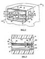
- la figure 1 représente, schématiquement enperspective, une enceinte de cuisson d'un four électriqueselon l'invention équipé d'un premier dispositif rotatifde reception.
- La figure 2 représente schématiquement enperspective à une échelle réduite un autre mode deréalisation d'un four électrique de cuisson selonl'invention, et équipé d'un second dispositif rotatif;
- La figure 3 est une coupe verticale, à échellelégèrement agrandie, selon la ligne I.I de la figure 2,mais dans laquelle le dispositif rotatif estpartiellement représenté;
- Les figures 4 et 5 sont des vues de face en coupede la cavité du four et du guide d'ondes selon deuxvariantes de réalisation possibles de l'invention.
- Figure 1 shows, schematically in perspective, a cooking chamber of an electric oven according to the invention equipped with a first rotary receiving device.
- FIG. 2 schematically shows in perspective on a reduced scale another embodiment of an electric cooking oven according to the invention, and equipped with a second rotary device;
- Figure 3 is a vertical section, on a slightly enlarged scale, along line II of Figure 2, but in which the rotary device is partially shown;
- Figures 4 and 5 are front sectional views of the oven cavity and the waveguide according to two possible embodiments of the invention.
Selon la figure 1, le four électrique de cuissoncomprend, entre autres, une source d'énergie micro-ondes2 telle que par exemple un magnétron, un guide d'ondes 3dont la sortie débouche dans une enceinte de cuissondélimitée par une paroi de fond 4, une paroi de voûte 5,une paroi de sole 6, deux parois latérales 7 et 8 et uneporte non représentée. Dans l'exemple représenté, lasource d'énergie micro-ondes 2 et le guide d'ondes 3 sontfixés sur la paroi latérale 8. L'enceinte de cuissonprésente, par exemple, la forme d'un parallélogramme,mais toute autre forme géométrique est envisageable. Lefour électrique de cuisson comporte, entre autres, undispositif rotatifR destiné à recevoir des plats ou desaliments à cuire et entraíné par des moyens de commande23 ( fig.3) placés à l'extérieur de l'enceinte decuisson, de préférence derrière la paroi de fond 4.According to FIG. 1, the electric cooking oven comprises, inter alia, a
Selon l'invention, le dispositif rotatifR comporteau moins deux plateaux rotatifs 9, 10, dits inférieur 9et supérieur 10, montés amovibles dans l'enceinte decuisson, superposés et espacés l'un de l'autre d'unedistanced, et la sortie du guide d'ondes 3 est adaptée à favoriser une bonne répartition des ondes sur les deuxplateaux 9 et 10.According to the invention, the rotary deviceR comprises at least two
Lesdits plateaux rotatifs sont, de préférence,circulaires. La source d'énergie micro-ondes émet, parexemple, un rayonnement dont la fréquence est de 2450Mhz.Said rotary tables are preferablycircular. The microwave energy source emits, byexample, a radiation whose frequency is 2450Mhz.
Sur la figure 1, on peut voir que l'enceinte decuisson comporte, pour chacun des plateaux rotatifs 9,10, deux moyens de guidage 11, 12; 13,14, dont un seul11; 13 desdits deux moyens de guidage est visible. Lesplateaux rotatifs supérieur 10 et inférieur 9 sont montésrespectivement en rotation par tous moyens connus sur dessupports amovibles 15, 16 reposant respectivement sur lesmoyens de guidage. Lesdits supports 15, 16 comportent desmoyens de transmission 19 du mouvement rotatif interposésen accouplement entre les moyens de commande 23 et leplateau rotatif 9; 10. Les moyens de commande 23 (nonreprésentés sur cette figure) sont agencés sur l'une aumoins des parois de l'enceinte et comportent au moins ungroupe moteur électrique. Les plateaux rotatifs supérieuret inférieur ayant des dimensions sensiblement voisinesdes dimensions de l'enceinte de cuisson, les deux moyensde guidage 11, 12; 13, 14 sont placés respectivement surchacune des parois latérales 7 et 8 de l'enceinte decuisson, afin de positionner aisément chacun des plateauxrotatifs. Comme on le voit, les deux moyens de guidage11, 12 du plateau inférieur 9 sont placés à proximité dela paroi de sole 6, et les deux moyens de guidage 13, 14du plateau supérieur 10 sont placés sensiblement à mi-hauteurdans l'enceinte de cuisson.In Figure 1, we can see that the enclosure ofcooking comprises, for each of the
De préférence, selon un mode de réalisation préféré,la sortie du guide d'ondes 3 comporte au moins deuxouvertures 30 et 32 (voir figure 4 ou 5) dont l'une 32est agencée entre les plateaux rotatifs 9; 10.Preferably, according to a preferred embodiment,the output of the
Dans les variantes de réalisation représentées surles figures 4 et 5, la sortie du guide d'ondes 3 comporte trois ouvertures 30, 31 et 32 : Une première ouverture 32est située entre les plateaux inférieur 9 et supérieur10; une deuxième ouverture 30 est située au-dessus duplateau supérieur 10; enfin, une ouverture intermédiaire31 est localisée soit au-dessous du plateau supérieur 10(figure 4), soit sensiblement au niveau de ce plateausupérieur 10 ( Figure 5) . Dans ce dernier cas, demeilleurs résultats dans la répartition des ondes sontobtenus en s'arrangeant pour que la majeure partie desondes issues du guide d'ondes par l'ouvertureintermédiaire 31 pénètre dans l'enceinte à un niveausitué au-dessous du plateau supérieur 10.In the variant embodiments shown onFigures 4 and 5, the output of the
Dans un exemple de réalisation préférentiel tel quereprésenté sur la figure 2, et dans lequel on a gardé lesmêmes références pour désigner des organes semblables,chacun des plateaux rotatifs 9; 10 est monté en rotationrespectivement sur un support amovible 15; 16 présentantla forme d'un plateau rectangulaire dont la largeur et laprofondeur sont pratiquement identiques à la largeur etla profondeur de l'intérieur de l'enceinte de cuisson.Chacun desdits supports amovibles 15; 16 comprend unepartie avant 17 et une partie arrière 18, ladite partiearrière 18 étant destinée à venir en appui contre laparoi de fond 4 lorsque ledit support amovible 15; 16 estcorrectement positionné à l'intérieur de l'enceinte decuisson. Chaque support amovible 15; 16 est constitué, depréférence, d'un matériau transparent aux micro-ondes telqu'un plastique, et le plateau rotatif 9; 10 est depréférence réalisé en verre trempé. Un tel supportamovible 15; 16 comporte des moyens de transmission 19(figure 3) interposés en accouplement entre les moyens decommande 23 et le plateau rotatif 9; 10. Le supportamovible est positionné, par exemple, sur des moyens deguidage 11, 12; 13, 14 fixés sur les parois latérales 7;8 de l'enceinte de cuisson, et présentant dans cetteréalisation la forme de glissière longitudinale.In a preferred embodiment such asshown in Figure 2, and in which we kept thesame references to designate similar bodies,each of the
Selon la figure 3, sur laquelle les éléments desfigures 1 et 2 sont désignés par les mêmes références,seuls le support amovible supérieur 16 et le plateau 10sont positionnés dans l'enceinte de cuisson.According to FIG. 3, in which the elements of theFIGS. 1 and 2 are designated by the same references,only the upper
Les moyens de transmission 19 du support amoviblesupérieur 16 comprennent un arbre 20 dont une extrémité21 est fixée sur la partie arrière 18 du support amovible16 en regard de la paroi de fond 4 et dont l'autreextrémité 22 est adaptée à venir s'accoupler avec lesmoyens de commande 23 comprenant, entre autres, un moteurélectrique non représenté. Lorsque l'utilisateur place lesupport amovible 16 dans l'enceinte de cuisson, l'arbre20 traverse un trou 24 réalisé dans la paroi de fond 4,ce qui facilite la liaison avec les moyens de commande23.The transmission means 19 of the removable supportupper 16 include a
Comme on le comprendra, les moyens de commande 23 etles moyens de transmission 19 pour le support amovible 15et le plateau 9 sont d'une construction semblable à celledécrite ci-dessus. Néanmoins, pour ce plateau inférieur9, on peut également envisager un autre plateau rotatifsans support coulissant, avec un moyen de commande enrotation agencé alors sous la sole 6 de manière connue ensoi.As will be understood, the control means 23 andthe transmission means 19 for the
Selon une réalisation différente non représentée d'unfour électrique de cuisson à micro-ondes , l'enceinte decuisson est munie en outre d'au moins une résistancechauffante placée sous la paroi de voûte 5. Laditerésistance est éloignée d'une hauteur appropriée duplateau rotatif supérieur 10 de manière à ce que lerayonnement infrarouge ne brûle pas les plats posés surle plateau 10.According to a different embodiment not shown of aelectric microwave oven, the ovencooking is additionally provided with at least one resistanceheater placed under the
D'autres variantes de réalisation sont possibles, parexemple, l'utilisation de trois supports amovibles.Other variant embodiments are possible, for exampleexample, the use of three removable media.
Grâce à l'invention ainsi réalisée, on comprendra quele four électrique de cuisson ainsi constitué est d'uneutilisation aisée pour l'utilisateur et facilite le traitement simultané de plusieurs plats et mets. Eneffet, l'utilisateur désirant traiter plusieurs plats oumets, positionne les différents supports amovibles dansl'enceinte de cuisson jusqu'à la position représentée surla figure 3. Ensuite, l'utilisateur place les récipientscontenant les plats à cuire sur chacun des plateauxrotatifs placés dans l'enceinte de cuisson. Leditutilisateur programme le four électrique selon la naturedes aliments constituant les plats placés dans laditeenceinte de cuisson et déclenche, après avoir vérifié lafermeture de la porte de l'enceinte de cuisson, lefonctionnement dudit four. Grâce à l'adaptation de lasortie du guide d'ondes 3 aux plateaux rotatifs demanière à obtenir une bonne répartition des ondes, etnotamment à la disposition de l'ouverture entre les deuxplateaux rotatifs 9; 10, on obtient un chauffagepratiquement homogène sur les deux étages des plateauxrotatifs.Thanks to the invention thus realized, it will be understood thatthe electric cooking oven thus constituted is ofeasy to use for the user and facilitatessimultaneous processing of several dishes and dishes. Ineffect, the user wishing to process several dishes orput, position the different removable supports inthe cooking chamber to the position shown onFigure 3. Next, the user places the containerscontaining the dishes to be cooked on each of the traysrotary placed in the cooking chamber. Saiduser programs the electric oven according to the typefoods constituting the dishes placed in saidcooking chamber and trips, after checking theclosing the oven door, theoperation of said oven. Thanks to the adaptation of theoutput of
D'autre part, en fonction des aliments à traiter,l'utilisateur peut positionner l'un et/ou l'autre desplateaux rotatifs amovibles dans l'enceinte de cuisson demanière à pouvoir traiter un ou plusieurs aliments.On the other hand, depending on the food to be treated,the user can position one and / or the other of theremovable rotating trays in the cooking chamberso that you can process one or more foods.
En outre, grâce aux moyens de transmission 19équipant les supports amovibles 15; 16, la mise en placeou l'enlèvement de ces supports est simple etautomatique, assurant ainsi, d'une part, une facilité denettoyage de l'enceinte de cuisson et, d'autre part, unegrande commodité d'utilisation du four pour une familled'utilisateurs.In addition, thanks to the transmission means 19fitted to the
Claims (9)
- An electric cooking oven comprising a microwave energysource (2), a waveguide (3) whose exit opens out into a cookingchamber delimited by a back wall (4), a top wall (5), a bottomwall (6) and two side walls (7) and (8) and a rotary device (R)internal to the cooking chamber, intended to receive food to becooked and driven in rotation by control means (23) placedoutside the cooking chamber, said rotary device (R) comprisingat least two rotary plates (9; 10) referred to as bottom (9)and top (10), and removably mounted within the cooking chamber,placed one above the other and spaced apart from each other bya distanced,
characterised in that the cooking chamber has two quidancemeans (11, 12; 13, 14) for each of the rotary plates (9; 10),the two guidance means of each plate being placed respectivelyon each of two side walls (7, 8) of the cooking chamber, andthe exit of the waveguide (3) being adapted to promote gooddistribution of the waves over the plates (9, 10). - Electric cooking oven according to claim 1,
characterised in that the two guidance means (11, 12) of thebottom plate (9) are placed close to the bottom wall (6) andthe two guidance means (13, 14) of the top plate (10) areplaced substantially halfway up in the cooking chamber. - Electric cooking oven according to claim 1 or 2,
characterised in that the exit of the waveguide (3) has atleast two openings, one of which is arranged between the rotaryplates (9; 10). - Electric cooking oven according to one of claims 1 to 3,
characterised in that each of the rotary plates (9; 10) ismounted on a removable support (15, 16) which, on the one hand,has means (19) for transmitting the rotary movement interposedso as to be coupled between control means (23) and the rotaryplate (9; 10) and, on the other hand, is positioned on the two guidance means (11, 12; 13, 14) fixed to the side wells (7; 8)of the cooking chamber. - Electric cooking oven according to claim 4,
characterised in that the removable support (15; 16) comprisinga front part (17) and a rear part (18), the means (19) fortransmitting the rotary movement of each of the rotary plates(9; 10) comprise a shaft (20), one end of which is fixed to therear part (18) of the removable support (15; 16) opposite theback wall (4) and the other end of which is adapted to come tobe coupled with the control means (23). - Electric cooking oven according to any one of the precedingclaims and whose chamber is provided with at least one heatingelement placed below the top wall (5),
characterised in that the heating element is distant by anappropriate height from the top rotary plate (10). - Electric cooking oven according to any one of the precedingclaims,
characterised in that the microwave energy source (2) has aradiation whose frequency is 2450 MHz. - Electric cooking oven according to any one of the precedingclaims,
characterised in that the exit of the waveguide (3) has a firstopening (32) situated between the top (10) and bottom (9)rotary plates, a second opening (30) situated above the toprotary plate (10), and a third intermediate opening (31)situated below the top rotary plate (10). - Electric cooking oven according to any one of claims 1 to 7,
characterised in that the exit of the waveguide (3) has a firstopening (32) situated between the top (10) and bottom (9)rotary plates, a second opening (30) situated above the toprotary plate (10) and a third intermediate opening (31)situated substantially at the level of the top rotary place(10).
Applications Claiming Priority (3)
| Application Number | Priority Date | Filing Date | Title |
|---|---|---|---|
| FR9510112 | 1995-08-25 | ||
| FR9510112AFR2738054B1 (en) | 1995-08-25 | 1995-08-25 | ELECTRIC COOKING OVEN |
| PCT/FR1996/001304WO1997008497A1 (en) | 1995-08-25 | 1996-08-22 | Electric oven |
Publications (2)
| Publication Number | Publication Date |
|---|---|
| EP0846244A1 EP0846244A1 (en) | 1998-06-10 |
| EP0846244B1true EP0846244B1 (en) | 2001-11-21 |
Family
ID=9482104
Family Applications (1)
| Application Number | Title | Priority Date | Filing Date |
|---|---|---|---|
| EP96929356AExpired - LifetimeEP0846244B1 (en) | 1995-08-25 | 1996-08-22 | Electric oven |
Country Status (11)
| Country | Link |
|---|---|
| US (1) | US6002120A (en) |
| EP (1) | EP0846244B1 (en) |
| JP (1) | JPH11511586A (en) |
| KR (1) | KR100443454B1 (en) |
| CN (1) | CN1122784C (en) |
| AT (1) | ATE209320T1 (en) |
| CA (1) | CA2227971A1 (en) |
| DE (1) | DE69617248D1 (en) |
| FR (1) | FR2738054B1 (en) |
| MX (1) | MX9801484A (en) |
| WO (1) | WO1997008497A1 (en) |
Families Citing this family (6)
| Publication number | Priority date | Publication date | Assignee | Title |
|---|---|---|---|---|
| US5796082A (en)* | 1995-10-26 | 1998-08-18 | Samsung Electronics Co., Ltd. | Microwave oven having partitions in cooking chamber for carrying rotary trays |
| FR2768494B1 (en)* | 1997-09-18 | 2000-04-21 | Moulinex Sa | ROTATING TRAY PLATE FOR MICROWAVE OVEN |
| KR100385045B1 (en)* | 1999-09-22 | 2003-05-22 | 삼성전자주식회사 | Microwave oven |
| KR100465191B1 (en)* | 2002-02-06 | 2005-01-13 | 삼성전자주식회사 | Microwave Range |
| DE102004059900B3 (en)* | 2004-12-13 | 2006-08-03 | Topinox Sarl | Cooking appliance with microwave generating device |
| DE102006012041A1 (en)* | 2006-03-16 | 2007-09-20 | Fraunhofer-Gesellschaft zur Förderung der angewandten Forschung e.V. | microwave oven |
Family Cites Families (7)
| Publication number | Priority date | Publication date | Assignee | Title |
|---|---|---|---|---|
| US3428772A (en)* | 1965-12-10 | 1969-02-18 | Hellige & Co Gmbh F | Microwave oven with rotatable shelf |
| US4140888A (en)* | 1976-12-01 | 1979-02-20 | Litton Systems, Inc. | Dual-feed microwave oven |
| US4337384A (en)* | 1979-08-01 | 1982-06-29 | Matsushita Electric Industrial Co., Ltd. | Cooking appliance of the hot air circulating type |
| US4329557A (en)* | 1979-12-07 | 1982-05-11 | General Electric Company | Microwave oven with improved energy distribution |
| JPS56149531A (en)* | 1980-04-22 | 1981-11-19 | Sharp Corp | Hot-air circulation type cooker |
| JPH0632295B2 (en)* | 1988-04-04 | 1994-04-27 | 三洋電機株式会社 | microwave |
| KR950014687A (en)* | 1993-11-13 | 1995-06-16 | 이헌조 | Microwave |
- 1995
- 1995-08-25FRFR9510112Apatent/FR2738054B1/ennot_activeExpired - Fee Related
- 1996
- 1996-08-22CACA002227971Apatent/CA2227971A1/ennot_activeAbandoned
- 1996-08-22CNCN96197623Apatent/CN1122784C/ennot_activeExpired - Fee Related
- 1996-08-22WOPCT/FR1996/001304patent/WO1997008497A1/enactiveIP Right Grant
- 1996-08-22DEDE69617248Tpatent/DE69617248D1/ennot_activeExpired - Lifetime
- 1996-08-22JPJP9509909Apatent/JPH11511586A/ennot_activeCeased
- 1996-08-22EPEP96929356Apatent/EP0846244B1/ennot_activeExpired - Lifetime
- 1996-08-22USUS09/011,908patent/US6002120A/ennot_activeExpired - Fee Related
- 1996-08-22ATAT96929356Tpatent/ATE209320T1/ennot_activeIP Right Cessation
- 1996-08-22KRKR10-1998-0701360Apatent/KR100443454B1/ennot_activeExpired - Fee Related
- 1998
- 1998-02-24MXMX9801484Apatent/MX9801484A/ennot_activeIP Right Cessation
Also Published As
| Publication number | Publication date |
|---|---|
| FR2738054A1 (en) | 1997-02-28 |
| ATE209320T1 (en) | 2001-12-15 |
| KR19990044127A (en) | 1999-06-25 |
| US6002120A (en) | 1999-12-14 |
| KR100443454B1 (en) | 2004-11-16 |
| FR2738054B1 (en) | 1999-01-22 |
| CN1122784C (en) | 2003-10-01 |
| CN1200168A (en) | 1998-11-25 |
| WO1997008497A1 (en) | 1997-03-06 |
| JPH11511586A (en) | 1999-10-05 |
| CA2227971A1 (en) | 1997-03-06 |
| MX9801484A (en) | 1998-11-30 |
| EP0846244A1 (en) | 1998-06-10 |
| DE69617248D1 (en) | 2002-01-03 |
Similar Documents
| Publication | Publication Date | Title |
|---|---|---|
| FR2514110A1 (en) | APPARATUS FOR COOKING OR HEATING FOOD | |
| FR3073127A1 (en) | COOKING APPARATUS FOR PASTRY PREPARATIONS | |
| FR2524616A1 (en) | MICROWAVE COOKING APPARATUS | |
| FR2868829A1 (en) | ELECTRIC OVEN FOR COOKING OR HEATING FOOD PRODUCTS SUPPORTED BY A ROTATING FRAME | |
| EP3785583B1 (en) | Hot air cooking appliance with several functional configurations | |
| EP0846244B1 (en) | Electric oven | |
| EP0332505B1 (en) | Microwave oven | |
| WO1989012417A1 (en) | Device for automatic cooking of food presented in a display pack | |
| EP0190430A1 (en) | Method and arrangement for heating foodstuffs | |
| FR2704738A1 (en) | Household oven. | |
| EP3710750A1 (en) | Cooking appliance for pastry preparations | |
| EP0609138A1 (en) | Microwave cooking apparatus | |
| EP3721760B1 (en) | Hot air cooking apparatus with a front opening for inserting and removing a cooking device | |
| WO2022023653A1 (en) | Automatic food preparation system | |
| EP4181746B1 (en) | Multi-purpose cooking device | |
| WO2000006415A1 (en) | Multipurpose wheeled cooking apparatus | |
| EP3785582B1 (en) | Hot air cooking appliance with compact size in a storage configuration | |
| EP3785584B1 (en) | Hot air cooking appliance provided with a base for receiving a cooking vessel and a locking device between the container and the base | |
| EP0358561A1 (en) | Cooking apparatus comprising a multifunctional enclosure with a micro-wave source | |
| EP0499570B1 (en) | Cooking device for foodstuffs | |
| EP2644031B1 (en) | Method for preparing French bread for bread machine | |
| FR2550432A1 (en) | MOBILE BAR, ESPECIALLY FOR OFFICES AND SMALL COMMUNITIES | |
| WO2025012541A1 (en) | Food heating appliance comprising a bowl having a reduced inner volume | |
| WO2025012543A1 (en) | Food heating appliance comprising a lid equipped with a heat shield portion | |
| EP4484830A1 (en) | Hot air cooking apparatus |
Legal Events
| Date | Code | Title | Description |
|---|---|---|---|
| PUAI | Public reference made under article 153(3) epc to a published international application that has entered the european phase | Free format text:ORIGINAL CODE: 0009012 | |
| 17P | Request for examination filed | Effective date:19980325 | |
| AK | Designated contracting states | Kind code of ref document:A1 Designated state(s):AT DE ES GB IT NL PT SE | |
| GRAG | Despatch of communication of intention to grant | Free format text:ORIGINAL CODE: EPIDOS AGRA | |
| 17Q | First examination report despatched | Effective date:20001106 | |
| GRAG | Despatch of communication of intention to grant | Free format text:ORIGINAL CODE: EPIDOS AGRA | |
| GRAH | Despatch of communication of intention to grant a patent | Free format text:ORIGINAL CODE: EPIDOS IGRA | |
| RAP1 | Party data changed (applicant data changed or rights of an application transferred) | Owner name:MOULINEX S.A. | |
| GRAH | Despatch of communication of intention to grant a patent | Free format text:ORIGINAL CODE: EPIDOS IGRA | |
| GRAA | (expected) grant | Free format text:ORIGINAL CODE: 0009210 | |
| RAP1 | Party data changed (applicant data changed or rights of an application transferred) | Owner name:MOULINEX S.A. | |
| AK | Designated contracting states | Kind code of ref document:B1 Designated state(s):AT DE ES GB IT NL PT SE | |
| PG25 | Lapsed in a contracting state [announced via postgrant information from national office to epo] | Ref country code:NL Free format text:LAPSE BECAUSE OF FAILURE TO SUBMIT A TRANSLATION OF THE DESCRIPTION OR TO PAY THE FEE WITHIN THE PRESCRIBED TIME-LIMIT Effective date:20011121 Ref country code:IT Free format text:LAPSE BECAUSE OF FAILURE TO SUBMIT A TRANSLATION OF THE DESCRIPTION OR TO PAY THE FEE WITHIN THE PRESCRIBED TIME-LIMIT;WARNING: LAPSES OF ITALIAN PATENTS WITH EFFECTIVE DATE BEFORE 2007 MAY HAVE OCCURRED AT ANY TIME BEFORE 2007. THE CORRECT EFFECTIVE DATE MAY BE DIFFERENT FROM THE ONE RECORDED. Effective date:20011121 Ref country code:AT Free format text:LAPSE BECAUSE OF FAILURE TO SUBMIT A TRANSLATION OF THE DESCRIPTION OR TO PAY THE FEE WITHIN THE PRESCRIBED TIME-LIMIT Effective date:20011121 | |
| REF | Corresponds to: | Ref document number:209320 Country of ref document:AT Date of ref document:20011215 Kind code of ref document:T | |
| GBT | Gb: translation of ep patent filed (gb section 77(6)(a)/1977) | Effective date:20011121 | |
| REG | Reference to a national code | Ref country code:GB Ref legal event code:IF02 | |
| REF | Corresponds to: | Ref document number:69617248 Country of ref document:DE Date of ref document:20020103 | |
| PG25 | Lapsed in a contracting state [announced via postgrant information from national office to epo] | Ref country code:SE Free format text:LAPSE BECAUSE OF FAILURE TO SUBMIT A TRANSLATION OF THE DESCRIPTION OR TO PAY THE FEE WITHIN THE PRESCRIBED TIME-LIMIT Effective date:20020221 Ref country code:PT Free format text:LAPSE BECAUSE OF FAILURE TO SUBMIT A TRANSLATION OF THE DESCRIPTION OR TO PAY THE FEE WITHIN THE PRESCRIBED TIME-LIMIT Effective date:20020221 | |
| PG25 | Lapsed in a contracting state [announced via postgrant information from national office to epo] | Ref country code:DE Free format text:LAPSE BECAUSE OF FAILURE TO SUBMIT A TRANSLATION OF THE DESCRIPTION OR TO PAY THE FEE WITHIN THE PRESCRIBED TIME-LIMIT Effective date:20020222 | |
| NLV1 | Nl: lapsed or annulled due to failure to fulfill the requirements of art. 29p and 29m of the patents act | ||
| PG25 | Lapsed in a contracting state [announced via postgrant information from national office to epo] | Ref country code:ES Free format text:LAPSE BECAUSE OF FAILURE TO SUBMIT A TRANSLATION OF THE DESCRIPTION OR TO PAY THE FEE WITHIN THE PRESCRIBED TIME-LIMIT Effective date:20020530 | |
| PG25 | Lapsed in a contracting state [announced via postgrant information from national office to epo] | Ref country code:GB Free format text:LAPSE BECAUSE OF NON-PAYMENT OF DUE FEES Effective date:20020822 | |
| PLBE | No opposition filed within time limit | Free format text:ORIGINAL CODE: 0009261 | |
| STAA | Information on the status of an ep patent application or granted ep patent | Free format text:STATUS: NO OPPOSITION FILED WITHIN TIME LIMIT | |
| 26N | No opposition filed | ||
| GBPC | Gb: european patent ceased through non-payment of renewal fee | Effective date:20020822 |