EP0842341B1 - Collapsible frame device - Google Patents
Collapsible frame deviceDownload PDFInfo
- Publication number
- EP0842341B1 EP0842341B1EP96926864AEP96926864AEP0842341B1EP 0842341 B1EP0842341 B1EP 0842341B1EP 96926864 AEP96926864 AEP 96926864AEP 96926864 AEP96926864 AEP 96926864AEP 0842341 B1EP0842341 B1EP 0842341B1
- Authority
- EP
- European Patent Office
- Prior art keywords
- base
- vehicle
- vehicle support
- members
- support member
- Prior art date
- Legal status (The legal status is an assumption and is not a legal conclusion. Google has not performed a legal analysis and makes no representation as to the accuracy of the status listed.)
- Expired - Lifetime
Links
- 238000012856packingMethods0.000claimsabstractdescription14
- 238000000034methodMethods0.000claimsabstractdescription8
- 230000015572biosynthetic processEffects0.000description9
- 238000005755formation reactionMethods0.000description9
- 238000003197gene knockdownMethods0.000description3
- 229910000746Structural steelInorganic materials0.000description1
- 238000010276constructionMethods0.000description1
- 230000000087stabilizing effectEffects0.000description1
Images


Classifications
- B—PERFORMING OPERATIONS; TRANSPORTING
- B65—CONVEYING; PACKING; STORING; HANDLING THIN OR FILAMENTARY MATERIAL
- B65D—CONTAINERS FOR STORAGE OR TRANSPORT OF ARTICLES OR MATERIALS, e.g. BAGS, BARRELS, BOTTLES, BOXES, CANS, CARTONS, CRATES, DRUMS, JARS, TANKS, HOPPERS, FORWARDING CONTAINERS; ACCESSORIES, CLOSURES, OR FITTINGS THEREFOR; PACKAGING ELEMENTS; PACKAGES
- B65D85/00—Containers, packaging elements or packages, specially adapted for particular articles or materials
- B65D85/68—Containers, packaging elements or packages, specially adapted for particular articles or materials for machines, engines or vehicles in assembled or dismantled form
- B—PERFORMING OPERATIONS; TRANSPORTING
- B65—CONVEYING; PACKING; STORING; HANDLING THIN OR FILAMENTARY MATERIAL
- B65D—CONTAINERS FOR STORAGE OR TRANSPORT OF ARTICLES OR MATERIALS, e.g. BAGS, BARRELS, BOTTLES, BOXES, CANS, CARTONS, CRATES, DRUMS, JARS, TANKS, HOPPERS, FORWARDING CONTAINERS; ACCESSORIES, CLOSURES, OR FITTINGS THEREFOR; PACKAGING ELEMENTS; PACKAGES
- B65D2585/00—Containers, packaging elements or packages specially adapted for particular articles or materials
- B65D2585/68—Containers, packaging elements or packages specially adapted for particular articles or materials for machines, engines, or vehicles in assembled or dismantled form
- B65D2585/6802—Containers, packaging elements or packages specially adapted for particular articles or materials for machines, engines, or vehicles in assembled or dismantled form specific machines, engines or vehicles
- B65D2585/686—Containers, packaging elements or packages specially adapted for particular articles or materials for machines, engines, or vehicles in assembled or dismantled form specific machines, engines or vehicles vehicles
- B65D2585/6867—Containers, packaging elements or packages specially adapted for particular articles or materials for machines, engines, or vehicles in assembled or dismantled form specific machines, engines or vehicles vehicles automobiles
- B—PERFORMING OPERATIONS; TRANSPORTING
- B65—CONVEYING; PACKING; STORING; HANDLING THIN OR FILAMENTARY MATERIAL
- B65G—TRANSPORT OR STORAGE DEVICES, e.g. CONVEYORS FOR LOADING OR TIPPING, SHOP CONVEYOR SYSTEMS OR PNEUMATIC TUBE CONVEYORS
- B65G2201/00—Indexing codes relating to handling devices, e.g. conveyors, characterised by the type of product or load being conveyed or handled
- B65G2201/02—Articles
- B65G2201/0294—Vehicle bodies
Definitions
- This inventionrelates to a collapsible frame device suitable for packing vehicles in a transport container.
- the inventionalso relates to a method of packing vehicles in a transport container.
- the one vehicleIn order to pack two motor vehicles into a standard six metre shipping container, the one vehicle is usually provided in an inclined position in the container with one end thereof located near the floor of the container and the other end provided near the roof of the container.
- the second vehicleis usually provided in a substantially horizontal position, parallel to the container floor, partly underneath the first vehicle.
- the same methodmay also be used to pack for example, four vehicles into a standard twelve metre shipping container.
- the frame devices used to pack vehicles in a transport containerare usually bulky and take up a lot of space when they have to be transported back after use.
- One such deviceis described in US-A-5213458.
- the arrangementis preferably such that the frame device can be erected and collapsed with relatively little effort.
- a collapsible frame devicesuitable for packing vehicles in a transport container having at least a floor and a wall structure, the frame device comprising a base which in use rests on the container floor; a first vehicle support means associated with the base for supporting a first vehicle in an inclined raised position relative to the base, the first vehicle support means comprising a lower vehicle support member and an upper vehicle support member, the support members in use in the erected configuration of the device being horizontally and vertically spaced from each other in order that the lower vehicle support member is relatively close to the base and that the upper vehicle support member is relatively high from the base; the lower and upper vehicle support members being collapsible onto the base to be located substantially flat onto the base in the collapsed configuration of the device; the arrangement being such that in the erected configuration of the device the device provides a space to receive a second vehicle at least partly beneath the first vehicle support means.
- vehiclemay in addition to its normal meaning also include a vehicle in semi knock-down form or a partly assembled vehicle.
- the first vehicle support meansmay also include a ramp means releasably connectable to the upper and lower vehicle support members to support the first vehicle thereon in an inclined raised position in the erected configuration of the device.
- This vehiclewill normally comprise a wheeled vehicle.
- mounting bracketsmay be provided to mount a vehicle in semi-knock down form or in a partly assembled form to the lower and upper vehicle support members.
- the basemay comprise a generally rectangularly shaped configuration defining two opposing long sides and two opposing short ends.
- the basemay be in the form of a frame.
- the basemay be provided with a number of wheels or rollers or the like whereupon the base in use slides.
- the lower and upper vehicle support membersmay each comprise a cross-bar which in use extends transversely across the base from one side to the other side; and two substantially upright members which in the erected configuration of the device extend upright from the base on opposite sides thereof in use to engage the cross-bar towards opposite ends thereof thereby in use supporting the cross-bar in an elevated position from the base.
- Each cross-barmay be releasably secured to the upright members.
- each cross-barincludes two projections which project transversely therefrom and which projections are telescopically associated with the upright members to connect them to each other.
- An upright member from the lower support member and an upright member from the upper support member located on one side of the basemay be connected to each other via a connecting member extending transversely between the said upright members preferably along the base of the device.
- the upright membersmay in the erected configuration of the device be connected to the base via the upright connecting member.
- an upright member from the lower support member and an upright member from the upper support member located on one side of the basemay be separate from each other. The distance between them may be adjustable.
- the upper and lower vehicle support membersmay be collapsible onto the base by folding them onto the base.
- the two substantially upright members of each support memberare folded towards each other onto the base.
- the two substantially upright members of each support memberare folded towards each other folding along lines extending along or parallel to the opposing long sides of the base where the base comprises a generally rectangular configuration defining two opposing long sides and two opposing short ends.
- the upright members of the support membersmay be hingedly attached to the base.
- the ramp meansmay comprise a pair of ramp members each ramp member comprising an elongate member which in the erected configuration of the device is releasably attachable to the upper and lower vehicle support members.
- the ramp meansmay be adapted in use to allow a vehicle to be driven thereon in the erected configuration of the device.
- the frame devicemay also include a second vehicle support means for supporting a second vehicle on the base in the space provided at least partly below the ramp means in the erected configuration of the device.
- the second vehicle support meansmay comprise a pair of tracks secured or securable to the base.
- the second vehicle support means in usepreferably supports the second vehicle in position generally parallel to the base.
- a collapsible frame devicesuitable for packing vehicles in a transport container having at least a floor and a wall structure, the frame device comprising an elongate base defining two opposing long sides, which base in use rests on the container floor; a first vehicle support means associated with the base for supporting a first vehicle in an inclined raised position relative to the base, the first vehicle support means comprising a lower vehicle support member and an upper vehicle support member, the support members in use in the erected configuration of the device being horizontally and vertically spaced from each other in order that the lower vehicle support member is relatively close to the base and that the upper vehicle support member is relatively high from the base; the lower and upper vehicle support members being collapsible onto the base in the collapsed configuration of the device by folding them onto the base along two lines each line extending along or parallel to a long side of the base; the arrangement being such that in the erected configuration of the device the device provides a space to receive a second vehicle at least partly beneath the first vehicle support means.
- the first vehicle support meansmay also include a ramp means connected or connectable to the upper and lower vehicle support members to support the first vehicle thereon in an inclined raised position in the erected configuration of the device.
- the inventionalso relates to the use of a frame device as described hereinabove for packing vehicles in a transport container.
- the one vehiclemay be driven onto the ramp means and preferably the other vehicle is also driven onto the frame device.
- a collapsible frame device 10suitable for packing vehicles 11 and 12 into a transport container 13.
- the container 13comprises a floor 13.1, a wall 13.2 a roof 13.3 and an opening 13.4 which is closeable by means of a door or the like [not shown].
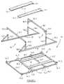
- the frame device 10comprises a base 14 which in use rests on the container floor 13.1.
- a first vehicle support means associated with the base 14is provided for supporting a first vehicle 11 in an inclined raised position relative to the base 14 is also provided.
- the first vehicle support meanscomprises a lower vehicle support member 15 and an upper vehicle support member 16, the members in use in the erected configuration of the device 10 [Figure 2] being horizontally and vertically spaced from each other.
- the lower vehicle support member 15is relatively close to the base 14 and the upper vehicle support member 16 is relatively high from the base 14 and in use they support a vehicle towards opposite ends of the vehicle to provide it in an inclined raised position.
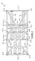
- the support members 15 and 16are also collapsible onto the base to be located substantially flat onto the base in the collapsed configuration of the device 10 [Figure 3].
- a ramp means in the form of a pair of ramp members 17are releasably connectable to the upper and lower vehicle support members 15 and 16 respectively to extend between them.
- a second vehicle support means 18is also provided for supporting a second vehicle 12 in a horizontal position relative to the base 14 in a space provided by the device 10 partly beneath the ramp members 17 and the first vehicle 11.
- the base 14comprises a generally rectangularly shaped frame.
- the framecomprises two opposing long side members 14.1 and two opposing short end members 14.2 extending between the long side members 14.1.
- Additional cross members 14.3are provided to extend between the side members 14.1.
- the base 14is adapted in use to fit into a standard six meter shipping container 13.
- the base 14is further provided with a number of wheels 14.4 whereupon the base 14 in use rides. Locating formations 14.5 are also provided on the base 14 to enhance positioning of the upper and lower support members 15 and 16 onto the base 14.
- the lower support member 15comprises a cross-bar 15.1 which in use extends across the base 14, from one side member 14.1 to the other, and two substantially upright members 15.2 extending upright from the base 14 on opposite sides thereof in the erected configuration of the device 10, that is upright from opposite side members 14.1 of the base 14.
- the upright members 15.2engage the cross-bar 15.1 on opposite ends thereof to support it in an elevated position relative to the base 14.
- the cross-bar 15.1includes two projections 15.3 projecting transversely therefrom, which projections 15.3 are telescopically associated with the upright members 15.2 to connect them releasably to each other.
- Two braces 15.4support the upright members 15.2.
- the upper support member 16also comprises a cross-bar 16.1, two upright members 16.2, two projections 16.3 and braces 16.4 and the arrangement is the same as described for the lower support member 15.
- braces 16.5are provided to provide strength to the cross-bar 16.1.
- Each pair of upright members 15.2 and 16.2 located on one side of the base 14are connected to each other via a connecting member 19 extending transversely between the said two upright members 15.2 and 16.2.
- the upright members 15.2 and 16.2are connected to the base 14 via the connecting member 19.
- the ramp members 17are releasably secured to the vehicle support members 15 and 16.
- Channel members 17.1provided at opposite sides of each ramp member 17, which channel members 17.1 in use hook over the cross-bars 15.1 and 16.1 respectively.
- the second vehicle support means 18comprises a pair of tracks secured to the base 14.
- two fully built-up vehicles 11 and 12may be provided on the device as shown in Figure 4 outside of the container.
- the first vehicle 11may be driven onto the ramp members 17, by providing a pair of additional ramp members [not shown] to extend from the ends of the ramp members 17 supported on the cross-bar 15.1, to the ground level. After driving the vehicle 11 onto the ramp members 17 the additional ramp members may be removed.
- the second vehicle 12may also be driven onto the tracks 18. Either the vehicle 11 or the vehicle 12 may be provided first onto the device 10.
- the device 10may be provided on a trolley 20 (or alternatively a pallet) which is then pushed against a transport container 13 as shown in Figure 5.
- the device 10 with vehicles 11 and 12are then pushed to slide on its wheels 14.4 into the container 13 as shown in Figure 6.
- the device 10 with vehicles 11 and 12 thereonmay be provided directly on a support surface and the container floor 13.1 may be provided on the same level as the support surface.
- the ramp device 10may then be slid into the container 13.
- semi-knock down vehiclesmay be secured onto the device 10.
- the ramps 17are removed and mounting means [not shown] is provided to mount the first vehicle body onto the cross-bars 15.1 and 16.1.
- the cross-bars 15.1 and 16.1are removed from the upright members 15.2 and 16.2 respectively and placed onto the base 14 as shown in Figure 3.
- the upright members 15.2 and 16.2are then folded onto the base towards each other as shown in Figure 3 by rotating them about the connecting members 19.
- a number of collapsed devices 10may be stacked onto each other. In this way a number of collapsed devices 10 can be transported in a single container to reduce transport costs.
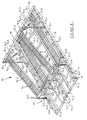
- an alternative collapsible frame device 70which operates basically the same as the device 10.
- the frame device 70comprises a base 71 and a first vehicle support means associated with the base 71 for supporting a first vehicle [not shown] in a inclined raised position relative to the base 71.
- the first vehicle support meanscomprises a lower vehicle support member 72 and an upper vehicle support member 73, the members in use in the erected configuration of the device 70 [Figure 8] being horizontally and vertically spaced from each other.
- the lower vehicle support member 72is relatively close to the base 71 and the upper vehicle support member 73 is relatively high form the base 71.
- the support members 72 and 73are also collapsible onto the base 71 to be located substantially flat onto the base 71 in the collapsed configuration of the device 70 [not shown].
- a ramp means in the form of a pair of ramp members 74are releasably connectable to the upper and lower vehicle support members 72 and 73 respectively.
- a second vehicle support means 75 in the form of a pair of tracks 75is also provided for supporting a second vehicle [not shown] on the base 71 in a horizontal position relative thereto in a space provided by the device 70 partly beneath the ramp members 74 and the first vehicle [not shown] supported thereon.
- the base 71comprises a generally rectangular shaped frame which is longitudinally receivable in a shipping container [not shown].
- the base 71comprises two opposing long side members 71.1 and two opposing short end members 71.2 and 71.3 respectively extending between the long side members 71.1.
- Additional elongate members 71.4are provided whereto the tracks 75 are mounted.
- Additional short members 71.5extend between the inner additional elongate member 71.4.
- Attachment members 71.6extend between the outer additional elongate member 71.4 and the long side members 71.1.
- the members 71.2, 71.5 and 71.6are provided slightly raised from a support surface whereupon the members 71.1 and 71.4 in use rests to reduce friction when the base 71 is in use slid on a support surface in a direction along the members 71.1 and 71.4.
- Figure 10shows the attachment for the short end member 71.2 to the members 71.1 and 71.4 [In this embodiment of the invention the base 71 is not provided with wheels].
- the base 71also includes engagement formations 71.7 in the form of tubular members engageable by an apparatus such as a fork-lift to lift the unloaded device 70, for example, when stacking after use.
- a support 71.8is provided between the engagement formations 71.7.
- An attachment formation 71.9[ Figures 7 and 11] in the form of an eye formation is provided on the short end member 71.2.
- the eye formation 71.9may be used to engage the device 70 when for example pulling it out of a shipping container.
- a shackle or the like attached to a cablemay be provided through the eye formation 71.9 and the cable may then be pulled to pull the device 70 out of the container.
- the lower support member 72comprises a cross-member 72.1 which in use extends across the base 71 from the one long side member 71.1 to the other.
- Two substantially upright members 72.2extend upright from the base 71 on opposite sides thereof in the erected configuration of the device 70, that is upright from opposite side members 71.1 of the base 71. In the erected configuration of the device 70, the upright members 72.2 engage the cross-member 72.1 on opposite ends thereof to support it in an elevated position relative to the base 71.
- the cross-member 72.1includes a cross-bar 72.6 and two projections 72.3 projecting transversely therefrom, which projections 72.3 are telescopically associated with the upright members 72.2 to slide into them thereby to connect them releasably to each other.
- the cross-member 72.1further includes three leg members 72.4 which in the erected configuration of the device 70 rests on the base 71 to provide stability to the lower support member 72. Additional stabilizing members 72.5 are also provided on the cross-members 72.1.
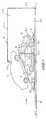
- Each upright member 72.2is mounted on a base member 72.7 [Figure 9].
- the base member 72.7extends through tubular members 72.8 thereby hingedly attaching the upright member 72.2 on the base 71 allowing the upright member 72.2 to be provided in an upright position as shown in Figure 9 or to fold down onto the base 71 by folding along a line extending longitudinally through the base member 72.7.
- the folding actionis indicated by arrow A.
- the base membermay also slide to and fro through the tubular members 72.8 as indicated by the arrow B to allow the distance between the lower support member 72 and the upper support member 73 to be adjusted.
- a locking means in the form of a locking pin 72.9 in use received through apertures 72.10 provided in a tubular members 72.8 and apertures 72.11 provided in the base member 72.7is provided to arrest the base member 72.7 from sliding through the tubular members 72.8 in the direction of arrow B.
- Each upright member 72.2is also provided with a brace 72.12 extending from the base member 72.7 to the upright member 72.2.
- the upper support member 73is similar in construction and operation as the tower support member 72 and also includes a cross-member 73.1 and two substantially upright members 73.2.
- the cross member 73.1includes a cross-bar 73.3 and two projections 73.4 for in use receiving therein spigots 73.5 on the upright members 73.2 to releasably connect the cross-member 73.1 to the upright members 73.2.
- Braces 73.6extend between each projection 73.4 and the cross-bar 73.3.
- Each upright member 73.2is also mounted on a base member 73.7 which is hingedly and slidingly attached to the base 71 via tubular members 73.8 in a similar manner as described for the lower support member 72. However, in this case no locking pin and holes are provided.
- Each upright member 73.2also includes a brace 73.9.
- Each ramp member 74comprises two angle-iron members 74.1 with cross-bars 74.2 extending between them.
- Each ramp member 74also includes channel members 74.3 on opposite sides thereof which in use hook over the cross-bars 72.6 and 73.3 respectively to releasably secure the ramp member 74 to the vehicle support members 72 and 73.
- Each track 75 on the base 71comprises of cross-bars 75.1 extending between the members 71.4.
- Additional ramp membersmay, in the erected configuration of the device 70, be attached to the lower ends of the ramp members 74 to allow a vehicle to be driven up onto the ramp members 74.
- the device 70may be used in a similar way as the device 10 to load vehicles into a transport container.
- Eye formations 76are provided on the device 70 for securing the vehicles [not shown] to the ramp device 70.
- the ramp members 74are removed and thereafter the cross-members 72.1 and 73.1.
- the upright members 72.2 and 73.2are then folded onto the base.
Landscapes
- Mechanical Engineering (AREA)
- Engineering & Computer Science (AREA)
- Pallets (AREA)
- Seal Device For Vehicle (AREA)
- Magnetic Resonance Imaging Apparatus (AREA)
- Separation By Low-Temperature Treatments (AREA)
- Packaging Of Machine Parts And Wound Products (AREA)
- Buffer Packaging (AREA)
- Carriages For Children, Sleds, And Other Hand-Operated Vehicles (AREA)
- Air Bags (AREA)
- Rigid Containers With Two Or More Constituent Elements (AREA)
- Management, Administration, Business Operations System, And Electronic Commerce (AREA)
- Passenger Equipment (AREA)
- Mirrors, Picture Frames, Photograph Stands, And Related Fastening Devices (AREA)
- Soil Working Implements (AREA)
Abstract
Description
- providing a frame device as described hereinabove inan erected configuration at least partly outside atransport container;
- providing two vehicles on the frame device, onevehicle on the first vehicle support means and theother on the base at least partly beneath the firstvehicle support means; and
- moving the frame device with the vehicles thereoninto the container.
- Figure 1
- is an exploded perspective view of theframe device according to the invention;
- Figure 2
- is a perspective view of the frame deviceof Figure 1 in its erected and assembledconfiguration;
- Figure 3
- is a plan view of the device of Figure 1in its collapsed configuration;
- Figure 4
- is a diagrammatic side view of twovehicles loaded onto the device of Figure2;
- Figure 5
- is a diagrammatic side view of thearrangement of Figure 4 being loaded intoa container;
- Figure 6
- is a diagrammatic side view of thearrangement of Figure 4 loaded into acontainer;
- Figure 7
- is an exploded perspective view of analternative frame device according to theinvention;
- Figure 8
- is a perspective view of the frame deviceof Figure 7 in its erected and assembledconfiguration;
- Figure 9
- is a perspective view of an uprightmember of the lower vehicle supportmember of the device of Figure 8;
- Figure 10
- is a perspective view of part of one endof the base of the device of Figure 7;and
- Figure 11
- is a perspective view of an attachmentformation on the device of Figure 7.
Claims (20)
- A collapsible frame device (10,70) suitable for packing vehicles (11,12) in a transportcontainer (13) having at least a floor (13.1) and a wall structure (13.2), the frame device (10,70) comprising:a base (14,71) which in use rests on the container floor (13.1);a first vehicle support means associated with the base for supporting a firstvehicle (11) in an inclined raised position relative to the base (14,71), the arrangement being such that, in the erected configuration of the device (10,70), thedevice (10,70) provides a space to receive a second vehicle (12) at least partly beneath the firstvehicle support means, the first vehicle supportmeans comprising:a lower vehicle support member (15,72) and an upper vehicle supportmember (16,73),characterized in that each lower vehicle support member (15,72) andeach upper vehicle support member (16,73) define substantially upright members and a cross-barwhich, in use in the erected configuration of the device (10,70), arehorizontally and vertically spaced from each other in order that thecross-bar of the lower vehicle support member (15,72) is relatively close tothe base (14,71), and the cross-bar of the upper vehicle support member (16,73) is relativelyhigh from the base (14,71); andthe lower (15,72) and upper vehicle support members (16,73) being collapsible ontothe base to be located substantially flat onto the base in the collapsedconfiguration of the device;andin that the first vehicle support means further includes ramp meanswhich is releasably connectable to the upper and lower vehiclesupport members to allow the ramp means to be removed duringcollapsing of said support members, the ramp means in use supportingthe first vehicle in an inclined raised position in the erectedconfiguration of the device (10,70).
- A device (10,70) as claimed in claim 1, wherein the ramp means comprises a pair oframp members (17,74).
- A device (10,70) as claimed in clam 1 or claim 2, wherein the base (14,71) comprises a framedefining two opposing long sides (14.1,71.1) and two opposing short ends (14.2,71.2).
- A device as (10,70) as claimed in claim 3, wherein the cross-bars (15.1,72.6,16.1,73.3) of the lower and uppervehicle support members each extends, in use, transversely across the base from oneside to the other side; and a respective pair of substantially upright members (15.2,72.2,16.2,73.2) which, inthe erected configuration of the device, extend upright from the base on opposite sidesthereof, to engage, in use, the associated cross-bar towards opposite ends thereof,thereby supporting the cross-bar, in use, in an elevated position from the base.
- A device (10,70) as claimed in any one of claims 1 to 4, wherein the upper (16,73) and lowervehicle support members (15,72) are collapsible onto the base (14,71) by folding them onto the base.
- A device (10,70) as claimed in claim 5, wherein each cross-bar (15.1,72.6,16.1,73.3) is releasably secured tothe upright members (15.2,72.2,16.2,73.2).
- A device (10,70) as claimed in claim 6, wherein each cross-bar (15.1,72.6,16.1,73.3) includes twoprojections (15.3,72.3,16.3,73.4) which project transversely therefrom, and which projections aretelescopically associated with the upright members (15.2,72.2,16.2,73.2) to connect them to each other.
- A device (10,70) as claimed in any one of claims 5 to 7, wherein the two substantiallyupright members of each support member are foldable towards each other onto the baseto collapse them onto the base.
- A device (10,70) as claimed in claim 8 when appendant to claim 3, wherein the twosubstantially upright members of each support member are foldable towards each otheralong lines extending along, or parallel to, the opposing long sides of the base (14.1,71.1).
- A device (10,70) as claimed in claim 9, wherein the upright members (15.2,72.2,16.2,73.2) of the supportmembers are hingedly attached to the base.
- A device (10,70) as claimed in any one of claims 1 to 10, wherein the ramp means (17,74) isadapted in use to allow a vehicle to be driven thereon in the erected configuration ofthe device.
- A device (10,70) as claimed in any one of claims 1 to 11, which includes a secondvehicle support means for supporting a second vehicle (12) on the base in the spaceprovided at least partly below the first vehicle support means in the erectedconfiguration of the device (10,70).
- A device (10,70) as claimed in claim 12, wherein the second vehicle support meanscomprises a pair of tracks (18,75) secured or securable to the base.
- A device (10,70) as claimed in claim 12 or claim 13, wherein the second vehiclesupport means supports, in use, the second vehicle (12) in a position generally parallel to thebase.
- A collapsible frame device (10,70) suitable for packing vehicles (11,72) in a transportcontainer (13) having at least a floor (13.1) and a wall structure (13.2), the frame device (10,70) comprising:an elongate base (14,71) defining two opposing long sides (14.1,71.1) and two opposing short ends (14.2,71.2)which base (14,71) in use rests on the container floor (13.1);a first vehicle support means associated with the base for supporting a firstvehicle (11) in an inclined raised position relative to the base (14,71); the arrangement being such that, in the erected configuration of the device (10,70), thedevice (10,70) provides a space to receive a second vehicle (12) at least partly beneath the firstvehicle support means,the first vehicle supportmeans comprising:a lower vehicle support member (15,72) and an upper vehicle supportmember (16,73), the support members, in use in the erected configuration ofthe device (10,70), being horizontally and vertically spaced from each other inorder that the lower vehicle support member (15,72) is relatively close to thebase, and that the upper vehicle support member (16,73) is relatively highfrom the base;characterized in thatthe lower (15,72) and upper vehicle support members (16,73) are collapsible ontothe base in the collapsed configuration of the device (10,70) by folding them onto the base about two axes, each axis extending along, or parallelto, a long side of the base (14.1,71.1).
- A device (10,70) as claimed in claim 15, wherein the first vehicle support means alsoincludes a ramp means (17,74) releasably connectable to the upper (16,73) and lower vehicle supportmembers (15,72) to support the first vehicle thereon in an inclined raised position in the erectedconfiguration of the device (10,70).
- The use of a frame device (10,70) of any one of the preceding claims for packingvehicles in a transport container.
- A method of packing vehicles (11,12) in a transport container (13), the method comprisingthe steps of:providing a frame device (10,70) of any one of claims 1 to 16 in an erectedconfiguration at least partly outside a transport container (13);providing two vehicles (11,12) on the frame device (10,70), one vehicle (11) on the first vehiclesupport means and the other on the base at least partly beneath the first vehiclesupport means; andmoving the frame device (10,70) with the vehicles (11,12) thereon into the container (13).
- A method as claimed in claim 18, wherein the one vehicle (11) is driven onto theramp means (17,74).
- A method as claimed in claim 19, wherein the other vehicle (12) is driven onto thebase (14,71).
Applications Claiming Priority (3)
| Application Number | Priority Date | Filing Date | Title |
|---|---|---|---|
| ZA9506441 | 1995-08-02 | ||
| ZA956441 | 1995-08-02 | ||
| PCT/US1996/012645WO1997005349A1 (en) | 1995-08-02 | 1996-08-01 | Collapsible frame device |
Publications (3)
| Publication Number | Publication Date |
|---|---|
| EP0842341A1 EP0842341A1 (en) | 1998-05-20 |
| EP0842341A4 EP0842341A4 (en) | 1999-01-13 |
| EP0842341B1true EP0842341B1 (en) | 2002-01-16 |
Family
ID=25585245
Family Applications (1)
| Application Number | Title | Priority Date | Filing Date |
|---|---|---|---|
| EP96926864AExpired - LifetimeEP0842341B1 (en) | 1995-08-02 | 1996-08-01 | Collapsible frame device |
Country Status (14)
| Country | Link |
|---|---|
| EP (1) | EP0842341B1 (en) |
| JP (1) | JP3773535B2 (en) |
| KR (1) | KR100450009B1 (en) |
| AT (1) | ATE211997T1 (en) |
| AU (1) | AU6688096A (en) |
| BR (1) | BR9609678A (en) |
| CY (1) | CY2266B1 (en) |
| DE (1) | DE69618602T2 (en) |
| DK (1) | DK0842341T3 (en) |
| ES (1) | ES2171702T3 (en) |
| MX (1) | MX9800892A (en) |
| PT (1) | PT842341E (en) |
| WO (1) | WO1997005349A1 (en) |
| ZA (1) | ZA966378B (en) |
Cited By (1)
| Publication number | Priority date | Publication date | Assignee | Title |
|---|---|---|---|---|
| CN104179376A (en)* | 2014-08-14 | 2014-12-03 | 山东上冶仓储科技有限公司 | Container type vehicle storage cabin |
Families Citing this family (8)
| Publication number | Priority date | Publication date | Assignee | Title |
|---|---|---|---|---|
| KR100790344B1 (en) | 2006-06-19 | 2008-01-04 | 주식회사 기성 | Pallet for Car Loading |
| EP2441701B1 (en) | 2010-10-15 | 2014-07-02 | Deutsche Post AG | Transport device and means of transport therewith |
| GB201110638D0 (en)* | 2011-06-23 | 2011-08-10 | Carling Maxwell A | Methods and systems for transporting loads |
| CN103086068B (en)* | 2013-02-05 | 2015-05-13 | 三一重机有限公司 | Fixing device and transporting device for transporting |
| DE102014219764A1 (en)* | 2014-09-30 | 2016-03-31 | Dürr Systems GmbH | Conveying device, drying plant and method for conveying workpieces |
| CN107882394B (en)* | 2017-11-17 | 2020-02-18 | 武汉理工大学 | Adjustable three-dimensional frame and container garage |
| CN113581598A (en)* | 2021-07-21 | 2021-11-02 | 宁波信泰机械有限公司 | Automobile door frame packaging support |
| CN116443435A (en)* | 2023-05-25 | 2023-07-18 | 长春一汽国际物流有限公司 | Packaging appliance for vehicle body transportation |
Family Cites Families (7)
| Publication number | Priority date | Publication date | Assignee | Title |
|---|---|---|---|---|
| US4124119A (en)* | 1977-08-02 | 1978-11-07 | Transequip Inc. | Automobile carrier for use on air cargo pallets |
| WO1987006895A1 (en)* | 1986-05-07 | 1987-11-19 | Mitsubishi Jidosha Kogyo Kabushiki Kaisha | Two-stage type device of loading automobile on container and operating method thereof |
| US5253975A (en)* | 1989-12-21 | 1993-10-19 | Taiyo Seiki Iron Works Co., Ltd. | Car loading apparatus |
| US5213458A (en)* | 1990-07-27 | 1993-05-25 | Sea-Land Corporation, Inc. | Method and apparatus for containerized shipment of automobiles |
| US5769591A (en)* | 1993-02-04 | 1998-06-23 | Kar-Tainer International, Inc. | Frame structure and method of packing vehicle bodies |
| US5454672A (en)* | 1993-03-17 | 1995-10-03 | G & G Intellectual Properties, Inc. | Adjustable load-carrying frame for fully utilizing transport enclosure space |
| US5427485A (en)* | 1994-02-23 | 1995-06-27 | Henderson; John W. B. | Pivoting movable ramp for transporting vehicles |
- 1996
- 1996-07-26ZAZA966378Apatent/ZA966378B/enunknown
- 1996-08-01DEDE69618602Tpatent/DE69618602T2/ennot_activeExpired - Lifetime
- 1996-08-01DKDK96926864Tpatent/DK0842341T3/enactive
- 1996-08-01JPJP50790297Apatent/JP3773535B2/ennot_activeExpired - Fee Related
- 1996-08-01KRKR10-1998-0700830Apatent/KR100450009B1/ennot_activeExpired - Fee Related
- 1996-08-01ATAT96926864Tpatent/ATE211997T1/ennot_activeIP Right Cessation
- 1996-08-01ESES96926864Tpatent/ES2171702T3/ennot_activeExpired - Lifetime
- 1996-08-01EPEP96926864Apatent/EP0842341B1/ennot_activeExpired - Lifetime
- 1996-08-01WOPCT/US1996/012645patent/WO1997005349A1/enactiveIP Right Grant
- 1996-08-01PTPT96926864Tpatent/PT842341E/enunknown
- 1996-08-01AUAU66880/96Apatent/AU6688096A/ennot_activeAbandoned
- 1996-08-01BRBR9609678-0Apatent/BR9609678A/ennot_activeIP Right Cessation
- 1998
- 1998-01-30MXMX9800892Apatent/MX9800892A/ennot_activeIP Right Cessation
- 2002
- 2002-04-16CYCY0200017Apatent/CY2266B1/enunknown
Cited By (1)
| Publication number | Priority date | Publication date | Assignee | Title |
|---|---|---|---|---|
| CN104179376A (en)* | 2014-08-14 | 2014-12-03 | 山东上冶仓储科技有限公司 | Container type vehicle storage cabin |
Also Published As
| Publication number | Publication date |
|---|---|
| BR9609678A (en) | 1999-12-21 |
| WO1997005349A1 (en) | 1997-02-13 |
| DK0842341T3 (en) | 2002-05-06 |
| KR100450009B1 (en) | 2005-05-19 |
| ZA966378B (en) | 1997-07-18 |
| DE69618602D1 (en) | 2002-02-21 |
| AU6688096A (en) | 1997-02-26 |
| CY2266B1 (en) | 2003-07-04 |
| EP0842341A4 (en) | 1999-01-13 |
| KR19990036162A (en) | 1999-05-25 |
| JP3773535B2 (en) | 2006-05-10 |
| EP0842341A1 (en) | 1998-05-20 |
| PT842341E (en) | 2002-07-31 |
| ATE211997T1 (en) | 2002-02-15 |
| MX9800892A (en) | 1998-09-30 |
| ES2171702T3 (en) | 2002-09-16 |
| DE69618602T2 (en) | 2002-09-12 |
| JPH11510759A (en) | 1999-09-21 |
Similar Documents
| Publication | Publication Date | Title |
|---|---|---|
| US5195726A (en) | Portable luggage carrier | |
| CA2798587C (en) | Pallet container | |
| US20010045718A1 (en) | Multiple function job site work cart | |
| US5887879A (en) | Cart assembly and methods | |
| CN110621595B (en) | Vehicle transport structure | |
| US5465987A (en) | Folding handtruck attachment | |
| US5570988A (en) | Cart carrying device | |
| US5924248A (en) | Collapsible frame device | |
| US8152014B2 (en) | Collapsible container system | |
| KR101984124B1 (en) | Transport device and transport means therewith | |
| EP0842341B1 (en) | Collapsible frame device | |
| US6010285A (en) | Collapsible vehicle transportation frame | |
| US4954038A (en) | Two-tier storage rack for vehicles | |
| US20090020576A1 (en) | Foldable chair | |
| EP3498632B1 (en) | Automobile transport frame for use in container, and container having same | |
| EP1009709A1 (en) | Load trays for personnel carrying vehicles | |
| US5280944A (en) | Carrier for transporting fence panels | |
| US6902033B2 (en) | Portable folding observation tower for attachment to a vehicle | |
| US4170182A (en) | Folding table structure | |
| GB2093806A (en) | Handling equipment for iso containers | |
| WO1995025023A1 (en) | Ramp apparatus | |
| WO2006041315A1 (en) | Foldable carrier | |
| FI86527C (en) | transport base | |
| GB2331285A (en) | Vehicle boot loading unit | |
| JPH0334392Y2 (en) |
Legal Events
| Date | Code | Title | Description |
|---|---|---|---|
| PUAI | Public reference made under article 153(3) epc to a published international application that has entered the european phase | Free format text:ORIGINAL CODE: 0009012 | |
| 17P | Request for examination filed | Effective date:19980213 | |
| AK | Designated contracting states | Kind code of ref document:A1 Designated state(s):AT BE CH DE DK ES FI FR GB GR IE IT LI LU MC NL PT SE | |
| A4 | Supplementary search report drawn up and despatched | Effective date:19981127 | |
| AK | Designated contracting states | Kind code of ref document:A4 Designated state(s):AT BE CH DE DK ES FI FR GB GR IE IT LI LU MC NL PT SE | |
| RHK1 | Main classification (correction) | Ipc:B65D 90/00 | |
| 17Q | First examination report despatched | Effective date:20000203 | |
| GRAG | Despatch of communication of intention to grant | Free format text:ORIGINAL CODE: EPIDOS AGRA | |
| GRAG | Despatch of communication of intention to grant | Free format text:ORIGINAL CODE: EPIDOS AGRA | |
| GRAG | Despatch of communication of intention to grant | Free format text:ORIGINAL CODE: EPIDOS AGRA | |
| GRAH | Despatch of communication of intention to grant a patent | Free format text:ORIGINAL CODE: EPIDOS IGRA | |
| GRAH | Despatch of communication of intention to grant a patent | Free format text:ORIGINAL CODE: EPIDOS IGRA | |
| GRAA | (expected) grant | Free format text:ORIGINAL CODE: 0009210 | |
| REG | Reference to a national code | Ref country code:GB Ref legal event code:IF02 | |
| AK | Designated contracting states | Kind code of ref document:B1 Designated state(s):AT BE CH DE DK ES FI FR GB GR IE IT LI LU MC NL PT SE | |
| REF | Corresponds to: | Ref document number:211997 Country of ref document:AT Date of ref document:20020215 Kind code of ref document:T | |
| REG | Reference to a national code | Ref country code:CH Ref legal event code:EP | |
| REG | Reference to a national code | Ref country code:IE Ref legal event code:FG4D | |
| REF | Corresponds to: | Ref document number:69618602 Country of ref document:DE Date of ref document:20020221 | |
| REG | Reference to a national code | Ref country code:DK Ref legal event code:T3 | |
| REG | Reference to a national code | Ref country code:CH Ref legal event code:NV Representative=s name:MICHELI & CIE INGENIEURS-CONSEILS | |
| ET | Fr: translation filed | ||
| REG | Reference to a national code | Ref country code:PT Ref legal event code:SC4A Free format text:AVAILABILITY OF NATIONAL TRANSLATION Effective date:20020410 | |
| REG | Reference to a national code | Ref country code:GR Ref legal event code:EP Ref document number:20020401415 Country of ref document:GR | |
| REG | Reference to a national code | Ref country code:ES Ref legal event code:FG2A Ref document number:2171702 Country of ref document:ES Kind code of ref document:T3 | |
| PLBE | No opposition filed within time limit | Free format text:ORIGINAL CODE: 0009261 | |
| STAA | Information on the status of an ep patent application or granted ep patent | Free format text:STATUS: NO OPPOSITION FILED WITHIN TIME LIMIT | |
| 26N | No opposition filed | ||
| PGFP | Annual fee paid to national office [announced via postgrant information from national office to epo] | Ref country code:MC Payment date:20040805 Year of fee payment:9 | |
| PGFP | Annual fee paid to national office [announced via postgrant information from national office to epo] | Ref country code:LU Payment date:20040806 Year of fee payment:9 Ref country code:CH Payment date:20040806 Year of fee payment:9 | |
| PGFP | Annual fee paid to national office [announced via postgrant information from national office to epo] | Ref country code:AT Payment date:20040810 Year of fee payment:9 | |
| PGFP | Annual fee paid to national office [announced via postgrant information from national office to epo] | Ref country code:BE Payment date:20040902 Year of fee payment:9 | |
| PGFP | Annual fee paid to national office [announced via postgrant information from national office to epo] | Ref country code:PT Payment date:20050729 Year of fee payment:10 | |
| PG25 | Lapsed in a contracting state [announced via postgrant information from national office to epo] | Ref country code:LU Free format text:LAPSE BECAUSE OF NON-PAYMENT OF DUE FEES Effective date:20050801 Ref country code:AT Free format text:LAPSE BECAUSE OF NON-PAYMENT OF DUE FEES Effective date:20050801 | |
| PGFP | Annual fee paid to national office [announced via postgrant information from national office to epo] | Ref country code:NL Payment date:20050812 Year of fee payment:10 Ref country code:FI Payment date:20050812 Year of fee payment:10 Ref country code:DK Payment date:20050812 Year of fee payment:10 | |
| PGFP | Annual fee paid to national office [announced via postgrant information from national office to epo] | Ref country code:IE Payment date:20050815 Year of fee payment:10 | |
| PGFP | Annual fee paid to national office [announced via postgrant information from national office to epo] | Ref country code:GR Payment date:20050830 Year of fee payment:10 | |
| PG25 | Lapsed in a contracting state [announced via postgrant information from national office to epo] | Ref country code:MC Free format text:LAPSE BECAUSE OF NON-PAYMENT OF DUE FEES Effective date:20050831 Ref country code:LI Free format text:LAPSE BECAUSE OF NON-PAYMENT OF DUE FEES Effective date:20050831 Ref country code:CH Free format text:LAPSE BECAUSE OF NON-PAYMENT OF DUE FEES Effective date:20050831 Ref country code:BE Free format text:LAPSE BECAUSE OF NON-PAYMENT OF DUE FEES Effective date:20050831 | |
| REG | Reference to a national code | Ref country code:CH Ref legal event code:PL | |
| PG25 | Lapsed in a contracting state [announced via postgrant information from national office to epo] | Ref country code:IE Free format text:LAPSE BECAUSE OF NON-PAYMENT OF DUE FEES Effective date:20060801 Ref country code:FI Free format text:LAPSE BECAUSE OF NON-PAYMENT OF DUE FEES Effective date:20060801 | |
| PG25 | Lapsed in a contracting state [announced via postgrant information from national office to epo] | Ref country code:DK Free format text:LAPSE BECAUSE OF NON-PAYMENT OF DUE FEES Effective date:20060831 | |
| PG25 | Lapsed in a contracting state [announced via postgrant information from national office to epo] | Ref country code:PT Free format text:LAPSE BECAUSE OF NON-PAYMENT OF DUE FEES Effective date:20070201 | |
| REG | Reference to a national code | Ref country code:PT Ref legal event code:MM4A Free format text:LAPSE DUE TO NON-PAYMENT OF FEES Effective date:20070201 | |
| PG25 | Lapsed in a contracting state [announced via postgrant information from national office to epo] | Ref country code:NL Free format text:LAPSE BECAUSE OF NON-PAYMENT OF DUE FEES Effective date:20070301 | |
| REG | Reference to a national code | Ref country code:DK Ref legal event code:EBP | |
| NLV4 | Nl: lapsed or anulled due to non-payment of the annual fee | Effective date:20070301 | |
| REG | Reference to a national code | Ref country code:IE Ref legal event code:MM4A | |
| BERE | Be: lapsed | Owner name:*KAR-TAINER INTERNATIONAL INC. Effective date:20050831 | |
| PG25 | Lapsed in a contracting state [announced via postgrant information from national office to epo] | Ref country code:GR Free format text:LAPSE BECAUSE OF NON-PAYMENT OF DUE FEES Effective date:20070302 | |
| PGFP | Annual fee paid to national office [announced via postgrant information from national office to epo] | Ref country code:ES Payment date:20080828 Year of fee payment:13 | |
| PGFP | Annual fee paid to national office [announced via postgrant information from national office to epo] | Ref country code:IT Payment date:20080826 Year of fee payment:13 Ref country code:FR Payment date:20080813 Year of fee payment:13 | |
| PGFP | Annual fee paid to national office [announced via postgrant information from national office to epo] | Ref country code:SE Payment date:20080815 Year of fee payment:13 | |
| REG | Reference to a national code | Ref country code:FR Ref legal event code:ST Effective date:20100430 | |
| PG25 | Lapsed in a contracting state [announced via postgrant information from national office to epo] | Ref country code:FR Free format text:LAPSE BECAUSE OF NON-PAYMENT OF DUE FEES Effective date:20090831 | |
| REG | Reference to a national code | Ref country code:ES Ref legal event code:FD2A Effective date:20090803 | |
| PG25 | Lapsed in a contracting state [announced via postgrant information from national office to epo] | Ref country code:IT Free format text:LAPSE BECAUSE OF NON-PAYMENT OF DUE FEES Effective date:20090801 | |
| PG25 | Lapsed in a contracting state [announced via postgrant information from national office to epo] | Ref country code:SE Free format text:LAPSE BECAUSE OF NON-PAYMENT OF DUE FEES Effective date:20090802 | |
| PG25 | Lapsed in a contracting state [announced via postgrant information from national office to epo] | Ref country code:ES Free format text:LAPSE BECAUSE OF NON-PAYMENT OF DUE FEES Effective date:20090802 | |
| PGFP | Annual fee paid to national office [announced via postgrant information from national office to epo] | Ref country code:DE Payment date:20150910 Year of fee payment:20 Ref country code:GB Payment date:20150917 Year of fee payment:20 | |
| REG | Reference to a national code | Ref country code:DE Ref legal event code:R071 Ref document number:69618602 Country of ref document:DE | |
| REG | Reference to a national code | Ref country code:GB Ref legal event code:PE20 Expiry date:20160731 | |
| PG25 | Lapsed in a contracting state [announced via postgrant information from national office to epo] | Ref country code:GB Free format text:LAPSE BECAUSE OF EXPIRATION OF PROTECTION Effective date:20160731 |