EP0841074A2 - Medical apparatus - Google Patents
Medical apparatusDownload PDFInfo
- Publication number
- EP0841074A2 EP0841074A2EP97118608AEP97118608AEP0841074A2EP 0841074 A2EP0841074 A2EP 0841074A2EP 97118608 AEP97118608 AEP 97118608AEP 97118608 AEP97118608 AEP 97118608AEP 0841074 A2EP0841074 A2EP 0841074A2
- Authority
- EP
- European Patent Office
- Prior art keywords
- linear oscillator
- variability
- pacemaker
- therapy
- modeling
- Prior art date
- Legal status (The legal status is an assumption and is not a legal conclusion. Google has not performed a legal analysis and makes no representation as to the accuracy of the status listed.)
- Granted
Links
- 238000002560therapeutic procedureMethods0.000claimsabstractdescription37
- 230000000739chaotic effectEffects0.000claimsabstractdescription25
- 238000013160medical therapyMethods0.000claimsabstractdescription24
- 230000035790physiological processes and functionsEffects0.000claimsabstractdescription17
- 230000000638stimulationEffects0.000claimsdescription17
- 238000005259measurementMethods0.000claimsdescription14
- 230000001419dependent effectEffects0.000claimsdescription8
- 238000000034methodMethods0.000claimsdescription8
- 238000012805post-processingMethods0.000claimsdescription8
- 239000011521glassSubstances0.000claimsdescription5
- 230000006870functionEffects0.000description10
- 238000010586diagramMethods0.000description8
- 230000006399behaviorEffects0.000description6
- 230000008859changeEffects0.000description6
- 238000004364calculation methodMethods0.000description5
- 230000001276controlling effectEffects0.000description5
- 238000004891communicationMethods0.000description4
- 230000002045lasting effectEffects0.000description4
- 230000000737periodic effectEffects0.000description4
- 238000012360testing methodMethods0.000description4
- 230000000747cardiac effectEffects0.000description3
- 238000011156evaluationMethods0.000description3
- 238000011835investigationMethods0.000description3
- 238000005070samplingMethods0.000description3
- 238000013459approachMethods0.000description2
- 230000008901benefitEffects0.000description2
- 238000006243chemical reactionMethods0.000description2
- 230000000694effectsEffects0.000description2
- 238000001727in vivoMethods0.000description2
- 238000012986modificationMethods0.000description2
- 230000004048modificationEffects0.000description2
- QVGXLLKOCUKJST-UHFFFAOYSA-Natomic oxygenChemical compound[O]QVGXLLKOCUKJST-UHFFFAOYSA-N0.000description1
- 238000010009beatingMethods0.000description1
- 239000008280bloodSubstances0.000description1
- 210000004369bloodAnatomy0.000description1
- 206010061592cardiac fibrillationDiseases0.000description1
- 230000006835compressionEffects0.000description1
- 238000007906compressionMethods0.000description1
- 230000002596correlated effectEffects0.000description1
- 230000002600fibrillogenic effectEffects0.000description1
- 210000005003heart tissueAnatomy0.000description1
- 238000002513implantationMethods0.000description1
- 238000001802infusionMethods0.000description1
- 230000005764inhibitory processEffects0.000description1
- 230000007246mechanismEffects0.000description1
- 210000005036nerveAnatomy0.000description1
- 229910052760oxygenInorganic materials0.000description1
- 239000001301oxygenSubstances0.000description1
- 230000029058respiratory gaseous exchangeEffects0.000description1
- 230000000284resting effectEffects0.000description1
- 230000035945sensitivityEffects0.000description1
- 230000000087stabilizing effectEffects0.000description1
- 238000010998test methodMethods0.000description1
- 238000012956testing procedureMethods0.000description1
- 230000002861ventricularEffects0.000description1
- 208000003663ventricular fibrillationDiseases0.000description1
Images


Classifications
- A—HUMAN NECESSITIES
- A61—MEDICAL OR VETERINARY SCIENCE; HYGIENE
- A61N—ELECTROTHERAPY; MAGNETOTHERAPY; RADIATION THERAPY; ULTRASOUND THERAPY
- A61N1/00—Electrotherapy; Circuits therefor
- A61N1/18—Applying electric currents by contact electrodes
- A61N1/32—Applying electric currents by contact electrodes alternating or intermittent currents
- A61N1/36—Applying electric currents by contact electrodes alternating or intermittent currents for stimulation
- A61N1/362—Heart stimulators
- A61N1/365—Heart stimulators controlled by a physiological parameter, e.g. heart potential
- A61N1/36514—Heart stimulators controlled by a physiological parameter, e.g. heart potential controlled by a physiological quantity other than heart potential, e.g. blood pressure
Definitions
- the present inventionis directed to devices for administering medical therapy to a subject, and in particular to an implantable device which administers for therapy artificially controlling a physiological function which has a natural variability.
- Many types of devicesare known in the art for administering medical therapy to a subject. Many devices of this type are implantable, and many also obtain a measurement of the controlling physiological variable by a sensor which is also implanted, and which is connected in vivo to the therapy-administering device. Examples of implantable medical devices of this type are pacemakers, defibrillators, nerve enervators, infusion pumps, etc. In the case of pacemakers, for example, it is well-known to control the timing and/or energy content (amplitude) of pacing pulses dependent on one or more physiological variables, such as activity, blood oxygen content, respiration, cardiac impedance, etc.
- Each of these physiological measurements, or a selected combination thereof,is analyzed within the pacemaker, such as by identification of periodic events (waveforms) which occur in the measured physiological signals, in order to select a basic pacing rate.
- this basic pacing rateOnce this basic pacing rate has been set, it will be used without variation until the occurrence of a subsequent "updating" routine, wherein the relevant measurement or measurements are repeated and again analyzed.
- the result of this updatemay indicate that the current basic rate is still suitable, and therefore no change in the basic pacing rate will be made.
- the current datamay indicate that an adjustment of the pacing rate is needed, in which case an increase or decrease in the pacing rate and/or energy content of the pacing pulses will be set by the pacemaker control electronics.
- Calculations made in conventional pacemaker electronicsresult in the emission of successive pacing pulses at precisely the same pulse-to-pulse interval, unless and until a change in the pacing rate is required. If, for example, as a result of the aforementioned physiological measurements and analysis, the pacemaker electronics determines that a basic pacing rate of 60 beats per minute (BPM) is warranted, the pulse generator of the pacemaker will be caused to emit a pacing pulse once each second, with exactly one second between the respective leading edges of successive pacing pulses. When examined closely, however, the natural behavior of the heart is not so precise.
- BPMbeats per minute
- United States Patent No. 5,265,617discloses a method and apparatus for non-invasively tracking and diagnosing cardiac vulnerability to ventricular defibrillation by identifying T-wave alternation and heart rate variability, and these phenomena are simultaneously analyzed and used to assess the extent and cause of cardiac vulnerability to ventricular fibrillation.
- a so-called chaotic systemis, in reality, deterministic in the sense that predictions as to the future behavior of the system can be made based on one or more fixed rules. Although the system may have an appearance of being random, this is usually because the system has not been observed for a sufficiently long time. In a true random system, the "randomness" of its behavior does not decrease when the observation time is increased. By contrast, the output of a chaotic system is, in principle, fully determined from its past history. In practice, however, many such system have variables which are exponentially sensitive to or dependent on the initial conditions at a given point in time, thereby making predictions about future behavior of the system extremely complicated, so that despite knowing the "rules" the systems are still unpredictable.
- a medical therapy apparatushaving means for generating a basic therapy for artificially controlling a physiological function of a subject, the physiological function having a natural variability associated therewith, a non-linear oscillator, means for matching the output of the non-linear oscillator to the natural variability of the physiological function to provide a variability adjustment, means for combining the basic therapy and the variability adjustment to generate a variability-adjusted therapy, and means for administering the variability-adjusted therapy to the subject.
- the medical therapy apparatusmay, for example, be a pacemaker, in which case the basic therapy will be a series of pacing pulses and the variability adjustment will be for the purpose of adjusting the timing between successive pulses in order to match the overall series of pacing pulses to the natural variability of the heartbeat rate of the subject.
- one or more physiological measurementscan be obtained from the subject, and the basic therapy can then be generated dependent on one of these measurements or a combination of these measurements.
- the non-linear oscillatorcan be constructed and operated so as to replicate any known, well understood chaotic system, such as the aforementioned Lorentz system, Duffin system, Rössler system or Mackey-Glass system.
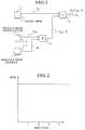
- Figure 1is a schematic block diagram for explaining the basic concept of the invention.
- Figure 2is a graph showing heartbeats per minute (BPM) versus time (measured in minutes) for illustrating the natural variability of the heartbeat rate.
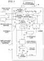
- FIG. 3is a block diagram of an implantable pacemaker constructed and operating in accordance with the principles of the present invention.
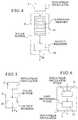
- Figure 4is a block diagram showing a first embodiment for the value buffer for use in the embodiment of Figure 3.
- FIG. 5is block diagram of a second embodiment for the value buffer for use in the pacemaker of Figure 3.
- FIG. 6is a block diagram for the non-linear oscillator for use in the pacemaker of Figure 3.
- Figures 7a and 7billustrate the influence of the non-linear oscillator in the pacemaker of Figure 3 on the stimulation rate, with a resolution of 0.01s.
- Figures 8a and 8billustrate the influence of the non-linear oscillator in the pacemaker of Figure 3 on the stimuation rate, with a resolution of 0.05s.
- Figures 9a and 9billustrate the influence of the non-linear oscillator in the pacemaker of Figure 3 on the stimuation rate, with a resolution of 0.10s.
- Figures 10a and 10billustrate the influence of the non-linear oscillator in the pacemaker of Figure 3 on the stimuation rate, with a resolution of 0.20s.
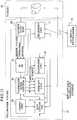
- FIG 11is a block diagram showing a pacemaker system employing a non-linear oscillator as a random variable generator for producing variables for a number of test procedures.
- FIG. 1is a schematic block diagram which illustrates the basic principles underlying the present invention.
- the block diagramillustrates an example wherein a set value (basic therapy) for a pacemaker stimulation rate is modulated a few beats per minute by a chaotic oscillator.
- a set value f bis emitted by a basic BPM unit 1.
- a non-linear (chaotic) oscillator 2emits an output f ch .
- This outputis multiplied by a modulation degree (scaling factor) k, emitted by a modulation degree unit 3.
- the multiplicationtakes place in a multiplier 4, to produce a product f ch ⁇ k.
- This productis added in an adder 5 to the set value f b , to produce the sum f b + f ch ⁇ k .
- This sumis then used to control the emission of stimulation pulses in a pacemaker, as described in more detail below.
- the product f ch ⁇ kconstitutes a variability adjustment
- the therapy administered dependent on the sum f b + f ch ⁇ kconstitutes variability-adjusted therapy.
- the modulation degree or scaling factor kcan be set at a constant value, or can be varied in a programmable or calculatable manner.
- the value of the modulation degree kdetermines the degree of modulation of the set value by the output of the non-linear oscillator 2. If the modulation degree is set to zero there will be no modulation at all.
- the set valuecan be the conventional rate set by known techniques in a pacemaker system, for example, the heartbeat rate measured in an activity-controlled pacemaker. As described in the embodiment discussed in detail below, it is an advantage if this rate, which be averaged over a floating time window, can be used to influence the modulation degree. This advantage can be achieved by using a fraction of the set value to control the value of the modulation degree k emitted by the modulation degree unit 3. Alternatively, the modulation degree k can be a constant value, and multiplication by the aforementioned fraction can take place in a separate multiplication stage, downstream from the modulation degree unit 3. Adjusting the modulation degree dependent on the set rate allows different rate modulations at different heartbeat rates.
- the beats per minuteis consistently at or near the basic value of 70, the time between successive beats will not be precisely 1 min./70, but will chaotically change relative to that basic value.
- FIG. 3An exemplary embodiment of a pacemaker operating in accordance with the principles of the present invention is shown in Figure 3.
- This systememploys a pacing functions unit 6, which includes a pulse generator of any suitable type.
- the pacing functions unit 6emits pacing pulses which are delivered to a subject via an electrode system 7, electrically connected to the pacing functions unit 6 in a known manner.
- the pacing functions unit 6may also be electrically connected to a physiological sensor 8 (as well as to additional physiological sensors, not shown) for receiving different types of physiological measurements from the subject.
- the pacing pulses emitted by the pacing functions unit 6 and delivered via the electrode system 7are intended to artificially control the heartbeat rate of the subject.
- the pacing functions unit 6is supplied with control signals from a control unit 9.
- the control unit 9is also in communication with a diagnostic unit 10, which can actively conduct diagnostics for checking the pacemaker operation, and can also store data for periodic interrogation by or dumping data to an external programmer 18.
- the external programmer 18is in communication with the implanted unit via a telemetry unit 17.
- the telemetry unit 17is in two-way communication with the control unit 9 for receiving data therefrom (as well as data from the diagnostic unit 10) and for supplying data and programming instructions thereto.
- the control unit 9also supplies control signals to the non-linear oscillator 2.
- the non-linear oscillator 2has an output connected to a value buffer 13, which is also controlled by the control unit 9.
- the output of the value bufferis a chaotic component F N , which is supplied to a modulation degree unit 3a.
- the modulation degree unit 3a in the embodiment of Figure 3is a combination of the modulation degree unit 3 and the multiplier 4 in the example of Figure 1, and thus emits an output which is a product k ⁇ F N .
- the modulation degree unit 3ais also controlled by the control unit 9.
- the output of the modulation degree unit 3ais supplied to the adder 5.
- Another input to the adder 5is supplied with a conventional pacing rate F C .
- This conventional pacing rateis determined by any suitable conventional manner.
- the measurement from the physiological sensor 8is evaluated within the pacing functions unit 6.
- the result of this evaluationis supplied to a rate register 11, wherein a number of different pacing rates are stored, correlated with different evaluation results, such as in a look-up table.
- the rate register 11emits an appropriate conventional pacing rate F C .
- the sum produced by the adder 5is supplied to a further rate register 12.
- the aforementioned rate register 11contains conventional rates at which the pacemaker would operate without the presence of the non-linear oscillator 2.
- the actual stimulation rate F s emitted by the rate register 12is, as described in connection with Figure 1, a combination of the conventional rate and the product of the chaotic rate F n multiplied by the modulation degree k. This value is supplied to the pacing functions unit 6, which emits pacing pulses at the variability-adjusted rate F S , which are delivered to the subject via the electrode system 7.
- a random component F Rin the calculation leading to the variability-adjusted stimulation rate F S .
- This optionis indicated by the generation of such a random component F R in a data table 15 contained in the control unit 9.
- the random component F Rcan be generated by another non-linear oscillator. If the random component F R is used, it is supplied to the adder 5 together with the product k ⁇ F N and F C , and is added to those values in the adder 5. This results in the random component F R being present as a further addend in the expression for the variability-adjusted stimulation F S .
- the optional presence of F R in that expressionis indicated by its inclusion within dashed line parentheses.
- Another optionis to initialize the data in the non-linear oscillator 2. It is known that some chaotic systems operate without any external data input, and these are known as autonomous oscillators or autonomous systems. By contrast, a non-autonomous system requires an external data feed. In addition to initializing the data in a non-linear oscillator 2, if the non-linear oscillator 2 is used to model a non-autonomous system, the data feed from the control unit 9 can also serve as the necessary external data feed. This option is indicated by a further data table 16 in the control unit 9.
- the output F N of the value buffer 13is preferably in digital form, and therefore the value buffer 13 can include an analog-to-digital converter if the active portion of the non-linear oscillator 2 produces an analog output. Alternatively, a separate analog-to-digital converter can be inserted between the value buffer 13 and the modulation degree unit 3a.
- one embodiment for the value buffer 13includes an N-position memory 19 and an output register 20.
- This embodimentassumes that the input to the N-position memory 19 will be in digital form, and thus if the output of the non-linear oscillator 2 is in analog form, an analog-to-digital converter will be included between the output of the non-linear oscillator 2 and the input of the N-position memory 19.
- the output of the non-linear oscillator 2either in its original digital form or after conversion, will typically contain four to eight bits of information.
- Each memory location of the N-position memory 19stores one output sample from the non-linear oscillator 2.
- the N-position memory 19can be organized a FIFO (first in, first out) memory.
- the N-position memory 19is operated by the aforementioned control signal from the control unit 9 which includes address, read and write controls.
- time “stretching”can be accomplished by rapid read-in and slow read-out of the memory 19.
- 1000 valuescan be obtained from the non-linear oscillator 2 and stored at a rapid speed, with one value then being read out for each stimulation (pacing) interval.
- the last internal states of the non-linear oscillator 2can be saved in a state memory (not shown) and then used to re-initialize the non-linear oscillator 2, instead of obtaining initialization data from the data table 16.
- the output register 20may be a part of the memory 19, however, it is also possible to operate without the memory 19 at all, in which case the output of the non-linear oscillator 2 (after analog-to-digital conversion, if necessary) is supplied directly to the output register 20, as shown in Figure 5.
- the value buffermerely includes the output register itself.
- This embodimentcan be used when the output of the non-linear oscillator 2 is digital, i.e., the result of solving a finite differential equation by software or digital hardware.
- the next step in the iteration of the non-linear oscillator 2is initiated by a new stimulation interval, i.e., each new interval produces the next value from the non-linear oscillator 2.
- the non-linear oscillator 2may include a non-linear oscillator stage 21 having an output connected to a post-processing stage 22, with the output of the post-processing stage 22 forming the output of the non-linear oscillator 2.
- This embodimenthas utility when the non-linear oscillator stage 21 is a "pure" oscillator, for example a Lorentz type oscillator.
- the post-processing stage 22can add a simple function, such as scaling or subtraction of a baseline, in order to make the average of the post-processing stage 22 equal to zero (i.e., the output of the post-processing stage 22 still exhibits non-zero values, but when averaged, these non-zero values produce an average of zero).
- a simple functionsuch as scaling or subtraction of a baseline
- Non-linear operationis also possible within the post-processing stage 22, for example a floating median value of the output of the non-linear oscillator stage 21 can be calculated over a number of samples of the output of the non-linear oscillator stage 21, for example, five samples.
- a pacemaker housing 14of a size and shape suitable for implantation in a subject.
- the output of the non-linear oscillator 2is shown in Figures 7a and 7b, 8a and 8b, 9a and 9b, and 10a and 10b respectively using different numbers of samples (i.e., different time steps).
- the output of the non-linear oscillator 2is the Z-component of a Lorentz system, with the nominal output value being processed so that the average level is zero, and the amplitude is at a 15% level.
- the original valueswere calculated rapidly, and stored in a memory.
- Figures 7a and 7bshow a time step of 0.01s. This means that the "sampling frequency" is 100 Hz, although this may not be the actual frequency in real time.
- the average paste rateis 70 BPM, with a substantially constant standard deviation calculated over a time interval of 100 beats (1 minute and 26 seconds).
- the resting rate in each exampleis the basic programmed rate in the pacemaker.
- Figures 8a and 8bshow the result with a resolution of 0.05s
- Figures 9a and 9bshow the result with a resolution of 0.10s
- Figures 10a and 10bshow the result with a resolution of 0.20s.
- Non-linear oscillator 2is used as a random data source in the operation of a pacemaker.
- An example of such a pacemakeris shown in Figure 11.
- a random data sourceis needed in certain types of control techniques, including programming, testing and load investigation procedures.
- components already identified in connection with the embodiment of Figure 3have been provided with the same reference numerals, and need not be described again.
- the pacemaker system shown in Figure 11interacts in vivo with a schematically-indicated patient 23, via leads and sensors of the type shown in more detail in Figure 3.
- Patient data editing stage 24which may also temporarily store incoming data. From the raw, incoming data, the patient data editing unit 24 generates, in a known manner, sensor values, inhibition signals and sensing signals, as needed.
- pacemaker mode control unit 9aThe pacemaker mode control unit is programmed to select one of several available therapy (pacing) modes t1, t2 or t3. Once the therapy mode has been selected, the pacemaker mode control unit 9a also controls the amplitude and timing of the emitted pulses, by means of a signal A.
- pacingtherapy
- the selected mode and the amplitude and timing signal Aare supplied to a therapy unit 27, which interacts with the patient 23 in a known manner to deliver the selected therapy.
- the pacemaker mode control unit 9ais connected to a conventional timing unit 26.
- the pacemaker mode control unit 9a and the timing unit 26are also both connected to the non-linear oscillator 2.
- the non-linear oscillator 2is also supplied with edited patient data from the patient data editing unit 24.
- the non-linear oscillator 2is also in communication with the diagnostic unit 10 and the telemetry unit 17 for assisting in programming and testing procedures.
Landscapes
- Health & Medical Sciences (AREA)
- Cardiology (AREA)
- Heart & Thoracic Surgery (AREA)
- Life Sciences & Earth Sciences (AREA)
- Biomedical Technology (AREA)
- Biophysics (AREA)
- Physiology (AREA)
- Engineering & Computer Science (AREA)
- Hematology (AREA)
- Nuclear Medicine, Radiotherapy & Molecular Imaging (AREA)
- Radiology & Medical Imaging (AREA)
- Animal Behavior & Ethology (AREA)
- General Health & Medical Sciences (AREA)
- Public Health (AREA)
- Veterinary Medicine (AREA)
- Electrotherapy Devices (AREA)
Abstract
Description
Claims (30)
- A medical therapy apparatus comprising:means for generating a basic therapy for artificially controlling aphysiological function of a subject, said physiological function havinga natural variability associated therewith;a non-linear oscillator having an output;means for matching said output of said non-linear oscillator to said naturalvariability of said physiological function to produce a variabilityadjustment;means for combining said basic therapy and said variability adjustment togenerate a variability-adjusted therapy; andmeans for administering said variability-adjusted therapy to said subject.
- A medical therapy apparatus asclaimed in claim 1 further comprising:means for obtaining a physiological measurement over time from saidsubject; andsaid means for artificially controlling a physiological function of said subjectcomprising means for artificially controlling said physiologicalfunction of said subject dependent on said physiologicalmeasurement.
- A medical therapy apparatus asclaimed in claim 1 wherein said means for matching said output of said non-linearoscillator to said natural variability of said physiological function comprises meansfor multiplying said output of said non-linear oscillator by a scaling factor.
- A medical therapy apparatus asclaimed in claim 3 wherein said basic therapy has a basic therapy valueassociated therewith, and further comprising means for setting said scaling factoras a fraction of said basic therapy value.
- A medical therapy apparatus asclaimed in claim 1 wherein said non-linear oscillator comprises means formodeling a chaotic system.
- A medical therapy apparatus asclaimed in claim 1 wherein said non-linear oscillator comprises means formodeling a Lorentz system.
- A medical therapy apparatus asclaimed in claim 1 wherein said non-linear oscillator comprises means formodeling a Duffin system.
- A medical therapy apparatus asclaimed in claim 1 wherein said non-linear oscillator comprises means formodeling a Rössler system.
- A medical therapy apparatus asclaimed in claim 1 wherein said non-linear oscillator comprises means formodeling a Mackey-Glass system.
- A medical therapy apparatus asclaimed in claim 1 further comprising means for generating a random value fromsaid basic therapy and wherein said means for combining comprises means forcombining said basic therapy, said variability adjustment and said random valueto generate said variability-adjusted therapy.
- A medical therapy apparatus asclaimed in claim 1 further comprising means for initializing said non-linearoscillator with initial data values.
- A medical therapy apparatus asclaimed in claim 1 wherein said non-linear oscillator comprises means formodeling an autonomous chaotic system.
- A medical therapy apparatus asclaimed in claim 1 wherein said non-linear oscillator comprises means formodeling a non-autonomous chaotic system and further comprising means forsupplying said means for modeling a non-autonomous chaotic system with anexternal data feed.
- A pacemaker for artificiallycontrolling a heartbeat rate of a subject, said heartbeat rate having a naturalvariability associated therewith, said pacemaker comprising:pulse generator means for generating a plurality of successive pacingpulses respectively separated by pulse intervals;control means for setting a basic pacing rate;a non-linear oscillator having an output;means for matching said output of said non-linear oscillator to said naturalvariability of said heartbeat rate to produce a variability adjustment;means for combining said basic rate with said variability adjustment togenerate a variability-adjusted stimulation rate, said pulse generatormeans emitting said stimulation pulses at said variability-adjustedstimulation rate; andmeans for delivering said stimulation pulses at said variability-adjustedstimulation rate to a heart of said subject.
- A pacemaker as claimed in claim14 further comprising:means for obtaining a physiological measurement over time from saidsubject; andsaid control means comprising means for artificially controlling saidphysiological function of said subject setting said basic pacing ratedependent on said physiological measurement.
- A pacemaker as claimed in claim14 wherein said means for matching said output of said non-linear oscillator tosaid natural variability of said physiological function comprises means formultiplying said output of said non-linear oscillator by a scaling factor.
- A pacemaker as claimed in claim16 further comprising means for setting said scaling factor as a fraction of saidbasic pacing rate.
- A pacemaker as claimed in claim14 wherein said non-linear oscillator comprises means for modeling a chaoticsystem.
- A pacemaker as claimed in claim14 wherein said non-linear oscillator comprises means for modeling a Lorentzsystem.
- A pacemaker as claimed in claim14 wherein said non-linear oscillator comprises means for modeling a Duffinsystem.
- A pacemaker as claimed in claim14 wherein said non-linear oscillator comprises means for modeling a Rösslersystem.
- A pacemaker as claimed in claim14 wherein said non-linear oscillator comprises means for modeling a Mackey-Glasssystem.
- A pacemaker as claimed in claim14 further comprising means for generating a random value from said basictherapy and wherein said means for combining comprises means for combiningsaid basic therapy, said variability adjustment and said random value to generatesaid variability-adjusted therapy.
- A pacemaker as claimed in claim14 further comprising means for initializing said non-linear oscillator with initialdata values.
- A pacemaker as claimed in claim14 wherein said non-linear oscillator comprises means for modeling anautonomous chaotic system.
- A pacemaker as claimed in claim14 wherein said non-linear oscillator comprises means for modeling a non-autonomouschaotic system and further comprising means for supplying saidmeans for modeling a non-autonomous chaotic system with an external data feed.
- A pacemaker as claimed in claim14 further comprising value buffer means connected between said output of saidnon-linear oscillator and said means for matching for controlling transfer of signalsfrom said output of said non-linear oscillator to said means for matching.
- A pacemaker as claimed in claim27 wherein said value buffer means comprises an N-position memory, controlledby said control means, for reading in and writing out values of said output of saidnon-linear oscillator, and said control means comprising means for controlling saidN-position memory for reading data into said N-position memory at a rate differentfrom reading out said data from said N-position memory.
- A pacemaker as claimed in claim14 wherein said non-linear oscillator comprises:a non-linear oscillator stage which models a chaotic system and whichemits a chaotic output; andpost-processing means, supplied with said chaotic output for generating anoutput having a time average of zero.
- A medical therapy apparatuscomprising:means for administering medical therapy to a subject;means for modeling a plurality of possible therapy procedures, eachtherapy procedure having a set of variables associated therewith, forobtaining a plurality of modeled therapy procedure results;random variable generator means, including a non-linear oscillator, forgenerating a plurality of random variables for use as said sets ofvariables; andmeans for selecting one of said modeled therapy procedure results asoptimum for a subject to whom said therapy is to be administered.
Applications Claiming Priority (2)
| Application Number | Priority Date | Filing Date | Title |
|---|---|---|---|
| US08/745,735US5690688A (en) | 1996-11-12 | 1996-11-12 | Medical therapy apparatus which administers therapy adjusted to follow natural variability of the physiological function being controlled |
| US745735 | 1996-11-12 |
Publications (3)
| Publication Number | Publication Date |
|---|---|
| EP0841074A2true EP0841074A2 (en) | 1998-05-13 |
| EP0841074A3 EP0841074A3 (en) | 1999-10-20 |
| EP0841074B1 EP0841074B1 (en) | 2005-06-15 |
Family
ID=24998031
Family Applications (1)
| Application Number | Title | Priority Date | Filing Date |
|---|---|---|---|
| EP97118608AExpired - LifetimeEP0841074B1 (en) | 1996-11-12 | 1997-10-27 | Medical apparatus |
Country Status (4)
| Country | Link |
|---|---|
| US (1) | US5690688A (en) |
| EP (1) | EP0841074B1 (en) |
| JP (1) | JPH10151209A (en) |
| DE (1) | DE69733531T2 (en) |
Cited By (5)
| Publication number | Priority date | Publication date | Assignee | Title |
|---|---|---|---|---|
| EP0793977A3 (en)* | 1996-03-04 | 1998-12-23 | BIOTRONIK Mess- und Therapiegeräte GmbH & Co Ingenieurbüro Berlin | Therapy device |
| WO2001074446A1 (en)* | 2000-03-29 | 2001-10-11 | Patent Max Q (P.M.Q) Ltd. | Implanted and programmable electrostimulator for stimulating organs and tissues of an organism |
| RU2277428C2 (en)* | 2004-05-12 | 2006-06-10 | Валерий Васильевич Бакуткин | Electrostimulator |
| RU2285549C2 (en)* | 2004-11-22 | 2006-10-20 | Александр Александрович Карасев | Electric neuro-adaptive stimulator and output cascade for it |
| CN1878595B (en)* | 2003-11-03 | 2010-11-10 | 坎纳基股份有限公司 | Intravenous cardiac pacing system with wireless power supply |
Families Citing this family (57)
| Publication number | Priority date | Publication date | Assignee | Title |
|---|---|---|---|---|
| JP2001239649A (en) | 2000-03-02 | 2001-09-04 | Ryobi Ltd | Printing system |
| US6775571B1 (en) | 2001-12-12 | 2004-08-10 | Pacesetter, Inc. | Dynamic control of overdrive pacing based on degree of randomness within heart rate |
| US6766194B1 (en) | 2001-12-12 | 2004-07-20 | Pacesetter, Inc. | Dynamic control of overdrive pacing based on degree of randomness within heart rate |
| US6694188B1 (en) | 2001-12-12 | 2004-02-17 | Pacesetter, Inc. | Dynamic control of overdrive pacing based on degree of randomness within heart rate |
| US9050469B1 (en) | 2003-11-26 | 2015-06-09 | Flint Hills Scientific, Llc | Method and system for logging quantitative seizure information and assessing efficacy of therapy using cardiac signals |
| US8260426B2 (en)* | 2008-01-25 | 2012-09-04 | Cyberonics, Inc. | Method, apparatus and system for bipolar charge utilization during stimulation by an implantable medical device |
| US9314633B2 (en) | 2008-01-25 | 2016-04-19 | Cyberonics, Inc. | Contingent cardio-protection for epilepsy patients |
| US8565867B2 (en) | 2005-01-28 | 2013-10-22 | Cyberonics, Inc. | Changeable electrode polarity stimulation by an implantable medical device |
| US8700163B2 (en) | 2005-03-04 | 2014-04-15 | Cyberonics, Inc. | Cranial nerve stimulation for treatment of substance addiction |
| US7840280B2 (en) | 2005-07-27 | 2010-11-23 | Cyberonics, Inc. | Cranial nerve stimulation to treat a vocal cord disorder |
| US7856273B2 (en) | 2005-07-28 | 2010-12-21 | Cyberonics, Inc. | Autonomic nerve stimulation to treat a gastrointestinal disorder |
| US20070025608A1 (en)* | 2005-07-29 | 2007-02-01 | Cyberonics, Inc. | Enhancing intrinsic neural activity using a medical device to treat a patient |
| US7620455B2 (en) | 2005-10-25 | 2009-11-17 | Cyberonics, Inc. | Cranial nerve stimulation to treat eating disorders |
| US8428731B2 (en) | 2005-10-27 | 2013-04-23 | Cyberonics, Inc. | Sequenced therapy protocols for an implantable medical device |
| US8694118B2 (en) | 2005-10-28 | 2014-04-08 | Cyberonics, Inc. | Variable output ramping for an implantable medical device |
| US7957796B2 (en)* | 2005-10-28 | 2011-06-07 | Cyberonics, Inc. | Using physiological sensor data with an implantable medical device |
| US20070173890A1 (en)* | 2006-01-24 | 2007-07-26 | Cyberonics, Inc. | Stimulation mode adjustment for an implantable medical device |
| US7996079B2 (en)* | 2006-01-24 | 2011-08-09 | Cyberonics, Inc. | Input response override for an implantable medical device |
| US7657310B2 (en) | 2006-01-26 | 2010-02-02 | Cyberonics, Inc. | Treatment of reproductive endocrine disorders by vagus nerve stimulation |
| US7801601B2 (en) | 2006-01-27 | 2010-09-21 | Cyberonics, Inc. | Controlling neuromodulation using stimulus modalities |
| EP3363495A1 (en) | 2006-03-29 | 2018-08-22 | Dignity Health | Microburst electrical stimulation of cranial nerves for the treatment of medical conditions |
| US7962220B2 (en)* | 2006-04-28 | 2011-06-14 | Cyberonics, Inc. | Compensation reduction in tissue stimulation therapy |
| US7869885B2 (en) | 2006-04-28 | 2011-01-11 | Cyberonics, Inc | Threshold optimization for tissue stimulation therapy |
| US7869867B2 (en) | 2006-10-27 | 2011-01-11 | Cyberonics, Inc. | Implantable neurostimulator with refractory stimulation |
| US7869884B2 (en)* | 2007-04-26 | 2011-01-11 | Cyberonics, Inc. | Non-surgical device and methods for trans-esophageal vagus nerve stimulation |
| US7904175B2 (en)* | 2007-04-26 | 2011-03-08 | Cyberonics, Inc. | Trans-esophageal vagus nerve stimulation |
| US7962214B2 (en)* | 2007-04-26 | 2011-06-14 | Cyberonics, Inc. | Non-surgical device and methods for trans-esophageal vagus nerve stimulation |
| US7974701B2 (en) | 2007-04-27 | 2011-07-05 | Cyberonics, Inc. | Dosing limitation for an implantable medical device |
| US9579506B2 (en) | 2008-01-25 | 2017-02-28 | Flint Hills Scientific, L.L.C. | Contingent cardio-protection for epilepsy patients |
| US8571643B2 (en) | 2010-09-16 | 2013-10-29 | Flint Hills Scientific, Llc | Detecting or validating a detection of a state change from a template of heart rate derivative shape or heart beat wave complex |
| US8337404B2 (en) | 2010-10-01 | 2012-12-25 | Flint Hills Scientific, Llc | Detecting, quantifying, and/or classifying seizures using multimodal data |
| US8382667B2 (en) | 2010-10-01 | 2013-02-26 | Flint Hills Scientific, Llc | Detecting, quantifying, and/or classifying seizures using multimodal data |
| US8204603B2 (en) | 2008-04-25 | 2012-06-19 | Cyberonics, Inc. | Blocking exogenous action potentials by an implantable medical device |
| US8457747B2 (en) | 2008-10-20 | 2013-06-04 | Cyberonics, Inc. | Neurostimulation with signal duration determined by a cardiac cycle |
| US8417344B2 (en) | 2008-10-24 | 2013-04-09 | Cyberonics, Inc. | Dynamic cranial nerve stimulation based on brain state determination from cardiac data |
| US20100191304A1 (en) | 2009-01-23 | 2010-07-29 | Scott Timothy L | Implantable Medical Device for Providing Chronic Condition Therapy and Acute Condition Therapy Using Vagus Nerve Stimulation |
| US8827912B2 (en) | 2009-04-24 | 2014-09-09 | Cyberonics, Inc. | Methods and systems for detecting epileptic events using NNXX, optionally with nonlinear analysis parameters |
| US8239028B2 (en) | 2009-04-24 | 2012-08-07 | Cyberonics, Inc. | Use of cardiac parameters in methods and systems for treating a chronic medical condition |
| US8831732B2 (en) | 2010-04-29 | 2014-09-09 | Cyberonics, Inc. | Method, apparatus and system for validating and quantifying cardiac beat data quality |
| US8562536B2 (en) | 2010-04-29 | 2013-10-22 | Flint Hills Scientific, Llc | Algorithm for detecting a seizure from cardiac data |
| US8649871B2 (en) | 2010-04-29 | 2014-02-11 | Cyberonics, Inc. | Validity test adaptive constraint modification for cardiac data used for detection of state changes |
| US8679009B2 (en) | 2010-06-15 | 2014-03-25 | Flint Hills Scientific, Llc | Systems approach to comorbidity assessment |
| US8641646B2 (en) | 2010-07-30 | 2014-02-04 | Cyberonics, Inc. | Seizure detection using coordinate data |
| US12383190B2 (en) | 2011-03-04 | 2025-08-12 | Flint Hills Scientific, Llc | Detecting, assessing and managing extreme seizure events |
| US8684921B2 (en) | 2010-10-01 | 2014-04-01 | Flint Hills Scientific Llc | Detecting, assessing and managing epilepsy using a multi-variate, metric-based classification analysis |
| US9504390B2 (en) | 2011-03-04 | 2016-11-29 | Globalfoundries Inc. | Detecting, assessing and managing a risk of death in epilepsy |
| US9656076B2 (en) | 2011-04-07 | 2017-05-23 | Nuvectra Corporation | Arbitrary waveform generator and neural stimulation application with scalable waveform feature and charge balancing |
| US8996117B2 (en)* | 2011-04-07 | 2015-03-31 | Greatbatch, Ltd. | Arbitrary waveform generator and neural stimulation application with scalable waveform feature |
| US8725239B2 (en) | 2011-04-25 | 2014-05-13 | Cyberonics, Inc. | Identifying seizures using heart rate decrease |
| US9402550B2 (en) | 2011-04-29 | 2016-08-02 | Cybertronics, Inc. | Dynamic heart rate threshold for neurological event detection |
| US9549677B2 (en) | 2011-10-14 | 2017-01-24 | Flint Hills Scientific, L.L.C. | Seizure detection methods, apparatus, and systems using a wavelet transform maximum modulus algorithm |
| US10448839B2 (en) | 2012-04-23 | 2019-10-22 | Livanova Usa, Inc. | Methods, systems and apparatuses for detecting increased risk of sudden death |
| US10220211B2 (en) | 2013-01-22 | 2019-03-05 | Livanova Usa, Inc. | Methods and systems to diagnose depression |
| US9056195B2 (en) | 2013-03-15 | 2015-06-16 | Cyberonics, Inc. | Optimization of cranial nerve stimulation to treat seizure disorderse during sleep |
| US9585611B2 (en) | 2014-04-25 | 2017-03-07 | Cyberonics, Inc. | Detecting seizures based on heartbeat data |
| US9302109B2 (en) | 2014-04-25 | 2016-04-05 | Cyberonics, Inc. | Cranial nerve stimulation to treat depression during sleep |
| GB2586987B (en) | 2019-09-10 | 2023-09-20 | Ceryx Medical Ltd | Pacemaker Device |
Citations (3)
| Publication number | Priority date | Publication date | Assignee | Title |
|---|---|---|---|---|
| US4732157A (en) | 1986-08-18 | 1988-03-22 | Massachusetts Institute Of Technology | Method and apparatus for quantifying beat-to-beat variability in physiologic waveforms |
| US5265617A (en) | 1991-02-20 | 1993-11-30 | Georgetown University | Methods and means for non-invasive, dynamic tracking of cardiac vulnerability by simultaneous analysis of heart rate variability and T-wave alternans |
| US5342401A (en) | 1992-08-19 | 1994-08-30 | The Regents Of The University Of California | Real time cardiac arrhythmia stabilizing system |
Family Cites Families (6)
| Publication number | Priority date | Publication date | Assignee | Title |
|---|---|---|---|---|
| US4153059A (en)* | 1977-10-25 | 1979-05-08 | Minnesota Mining And Manufacturing Company | Urinary incontinence stimulator system |
| US4210151A (en)* | 1978-09-26 | 1980-07-01 | Stimtech, Inc. | Electronic pain control with scanned output parameters |
| DD230730A3 (en)* | 1984-01-02 | 1985-12-11 | Zentralinstitut Fuer Diabetes | DEVICE FOR THE PROSPECTIVE AUTOMATIC DETERMINATION OF INDIVIDUAL-SPECIFIC GLUCOSE REGULATION PARAMETERS |
| AU3070495A (en)* | 1994-07-13 | 1996-02-16 | Gw Scientific Inc. | Detection of abnormal and induction of normal heart rate variability |
| US5647663A (en)* | 1996-01-05 | 1997-07-15 | Wisconsin Alumni Research Foundation | Radiation treatment planning method and apparatus |
| DE19609409C2 (en)* | 1996-03-04 | 2000-01-20 | Biotronik Mess & Therapieg | Therapy device |
- 1996
- 1996-11-12USUS08/745,735patent/US5690688A/ennot_activeExpired - Lifetime
- 1997
- 1997-10-27DEDE69733531Tpatent/DE69733531T2/ennot_activeExpired - Lifetime
- 1997-10-27EPEP97118608Apatent/EP0841074B1/ennot_activeExpired - Lifetime
- 1997-11-12JPJP9310121Apatent/JPH10151209A/enactivePending
Patent Citations (4)
| Publication number | Priority date | Publication date | Assignee | Title |
|---|---|---|---|---|
| US4732157A (en) | 1986-08-18 | 1988-03-22 | Massachusetts Institute Of Technology | Method and apparatus for quantifying beat-to-beat variability in physiologic waveforms |
| US5265617A (en) | 1991-02-20 | 1993-11-30 | Georgetown University | Methods and means for non-invasive, dynamic tracking of cardiac vulnerability by simultaneous analysis of heart rate variability and T-wave alternans |
| US5342401A (en) | 1992-08-19 | 1994-08-30 | The Regents Of The University Of California | Real time cardiac arrhythmia stabilizing system |
| US5447520A (en) | 1992-08-19 | 1995-09-05 | The Regents Of The University Of California | Real time stabilizing system for pulsating activity |
Cited By (6)
| Publication number | Priority date | Publication date | Assignee | Title |
|---|---|---|---|---|
| EP0793977A3 (en)* | 1996-03-04 | 1998-12-23 | BIOTRONIK Mess- und Therapiegeräte GmbH & Co Ingenieurbüro Berlin | Therapy device |
| WO2001074446A1 (en)* | 2000-03-29 | 2001-10-11 | Patent Max Q (P.M.Q) Ltd. | Implanted and programmable electrostimulator for stimulating organs and tissues of an organism |
| RU2243790C2 (en)* | 2000-03-29 | 2005-01-10 | Карашуров Сергей Егорович | Implantable programmable electrostimulator for stimulating organs and tissues in organism |
| CN1878595B (en)* | 2003-11-03 | 2010-11-10 | 坎纳基股份有限公司 | Intravenous cardiac pacing system with wireless power supply |
| RU2277428C2 (en)* | 2004-05-12 | 2006-06-10 | Валерий Васильевич Бакуткин | Electrostimulator |
| RU2285549C2 (en)* | 2004-11-22 | 2006-10-20 | Александр Александрович Карасев | Electric neuro-adaptive stimulator and output cascade for it |
Also Published As
| Publication number | Publication date |
|---|---|
| US5690688A (en) | 1997-11-25 |
| EP0841074B1 (en) | 2005-06-15 |
| JPH10151209A (en) | 1998-06-09 |
| DE69733531D1 (en) | 2005-07-21 |
| EP0841074A3 (en) | 1999-10-20 |
| DE69733531T2 (en) | 2006-05-11 |
Similar Documents
| Publication | Publication Date | Title |
|---|---|---|
| US5690688A (en) | Medical therapy apparatus which administers therapy adjusted to follow natural variability of the physiological function being controlled | |
| US7972275B2 (en) | Method and apparatus for monitoring of diastolic hemodynamics | |
| US5081987A (en) | Implantable medical device for stimulating a physiological event of a living being with stimulation intensity adaptable to physical activity of the living being | |
| US7123962B2 (en) | Phonocardiographic image-based atrioventricular delay optimization | |
| US5476484A (en) | Apparatus for sensing a physical condition in a living subject | |
| US7248923B2 (en) | Dual-use sensor for rate responsive pacing and heart sound monitoring | |
| US7317941B2 (en) | Time syncrhonization of data | |
| US8175695B2 (en) | T-wave alternans train spotter | |
| US8255053B2 (en) | Method and apparatus for question-based programming of cardiac rhythm management devices | |
| US5692907A (en) | Interactive cardiac rhythm simulator | |
| EP1561489A2 (en) | Transvalvular impedance measurement | |
| JPH10509633A (en) | Device for annotating physiological waveforms | |
| JPH09225043A (en) | Rate response type heart stimulation method and its pace maker | |
| US20110160789A1 (en) | Modulation of AV Delay to Control Ventricular Interval Variability | |
| EP1222942B1 (en) | System for automating capture verification assessment and pacing threshold assessment using a programmer | |
| US7930019B2 (en) | Method and apparatus for phonocardiographic image acquisition and presentation | |
| Augustynek et al. | An Artificial Heart System for Testing and Evaluation of Cardiac Pacemakers | |
| Kordon et al. | Case Study: Pacemaker | |
| WANG | Identification and Documentation of Environmental Assumptions for the PACEMAKER System | |
| US20130023947A1 (en) | Implantable Heart Stimulator |
Legal Events
| Date | Code | Title | Description |
|---|---|---|---|
| PUAI | Public reference made under article 153(3) epc to a published international application that has entered the european phase | Free format text:ORIGINAL CODE: 0009012 | |
| AK | Designated contracting states | Kind code of ref document:A2 Designated state(s):DE ES FR GB IT NL | |
| PUAL | Search report despatched | Free format text:ORIGINAL CODE: 0009013 | |
| AK | Designated contracting states | Kind code of ref document:A3 Designated state(s):AT BE CH DE DK ES FI FR GB GR IE IT LI LU MC NL PT SE | |
| 17P | Request for examination filed | Effective date:20000420 | |
| AKX | Designation fees paid | Free format text:DE ES FR GB IT NL | |
| RAP1 | Party data changed (applicant data changed or rights of an application transferred) | Owner name:ST. JUDE MEDICAL AB | |
| 17Q | First examination report despatched | Effective date:20030509 | |
| GRAP | Despatch of communication of intention to grant a patent | Free format text:ORIGINAL CODE: EPIDOSNIGR1 | |
| GRAS | Grant fee paid | Free format text:ORIGINAL CODE: EPIDOSNIGR3 | |
| GRAA | (expected) grant | Free format text:ORIGINAL CODE: 0009210 | |
| AK | Designated contracting states | Kind code of ref document:B1 Designated state(s):DE ES FR GB IT NL | |
| PG25 | Lapsed in a contracting state [announced via postgrant information from national office to epo] | Ref country code:NL Free format text:LAPSE BECAUSE OF FAILURE TO SUBMIT A TRANSLATION OF THE DESCRIPTION OR TO PAY THE FEE WITHIN THE PRESCRIBED TIME-LIMIT Effective date:20050615 | |
| REG | Reference to a national code | Ref country code:GB Ref legal event code:FG4D | |
| RIN1 | Information on inventor provided before grant (corrected) | Inventor name:HIRSCHBERG, JAKUB Inventor name:NOREN, KJELL | |
| REF | Corresponds to: | Ref document number:69733531 Country of ref document:DE Date of ref document:20050721 Kind code of ref document:P | |
| PG25 | Lapsed in a contracting state [announced via postgrant information from national office to epo] | Ref country code:ES Free format text:LAPSE BECAUSE OF FAILURE TO SUBMIT A TRANSLATION OF THE DESCRIPTION OR TO PAY THE FEE WITHIN THE PRESCRIBED TIME-LIMIT Effective date:20050926 | |
| PG25 | Lapsed in a contracting state [announced via postgrant information from national office to epo] | Ref country code:GB Free format text:LAPSE BECAUSE OF NON-PAYMENT OF DUE FEES Effective date:20051027 | |
| NLV1 | Nl: lapsed or annulled due to failure to fulfill the requirements of art. 29p and 29m of the patents act | ||
| ET | Fr: translation filed | ||
| PLBE | No opposition filed within time limit | Free format text:ORIGINAL CODE: 0009261 | |
| STAA | Information on the status of an ep patent application or granted ep patent | Free format text:STATUS: NO OPPOSITION FILED WITHIN TIME LIMIT | |
| 26N | No opposition filed | Effective date:20060316 | |
| GBPC | Gb: european patent ceased through non-payment of renewal fee | Effective date:20051027 | |
| PGFP | Annual fee paid to national office [announced via postgrant information from national office to epo] | Ref country code:IT Payment date:20061031 Year of fee payment:10 | |
| REG | Reference to a national code | Ref country code:FR Ref legal event code:ST Effective date:20080630 | |
| PGFP | Annual fee paid to national office [announced via postgrant information from national office to epo] | Ref country code:FR Payment date:20060929 Year of fee payment:10 | |
| PG25 | Lapsed in a contracting state [announced via postgrant information from national office to epo] | Ref country code:FR Free format text:LAPSE BECAUSE OF NON-PAYMENT OF DUE FEES Effective date:20071031 | |
| PG25 | Lapsed in a contracting state [announced via postgrant information from national office to epo] | Ref country code:IT Free format text:LAPSE BECAUSE OF NON-PAYMENT OF DUE FEES Effective date:20071027 | |
| PGFP | Annual fee paid to national office [announced via postgrant information from national office to epo] | Ref country code:DE Payment date:20091027 Year of fee payment:13 | |
| REG | Reference to a national code | Ref country code:DE Ref legal event code:R119 Ref document number:69733531 Country of ref document:DE Effective date:20110502 | |
| PG25 | Lapsed in a contracting state [announced via postgrant information from national office to epo] | Ref country code:DE Free format text:LAPSE BECAUSE OF NON-PAYMENT OF DUE FEES Effective date:20110502 |