EP0841073B1 - Retrograde coronary sinus catheter - Google Patents
Retrograde coronary sinus catheterDownload PDFInfo
- Publication number
- EP0841073B1 EP0841073B1EP98100991AEP98100991AEP0841073B1EP 0841073 B1EP0841073 B1EP 0841073B1EP 98100991 AEP98100991 AEP 98100991AEP 98100991 AEP98100991 AEP 98100991AEP 0841073 B1EP0841073 B1EP 0841073B1
- Authority
- EP
- European Patent Office
- Prior art keywords
- catheter
- balloon
- coronary sinus
- infusion lumen
- tube
- Prior art date
- Legal status (The legal status is an assumption and is not a legal conclusion. Google has not performed a legal analysis and makes no representation as to the accuracy of the status listed.)
- Expired - Lifetime
Links
- 210000003748coronary sinusAnatomy0.000titleclaimsdescription68
- 238000001802infusionMethods0.000claimsdescription56
- 239000012530fluidSubstances0.000claimsdescription28
- 229940100084cardioplegia solutionDrugs0.000claimsdescription14
- 239000003292glueSubstances0.000claimsdescription5
- 239000007787solidSubstances0.000claimsdescription3
- 238000000034methodMethods0.000description21
- 238000004891communicationMethods0.000description13
- 230000014759maintenance of locationEffects0.000description13
- 210000005245right atriumAnatomy0.000description11
- 239000000463materialSubstances0.000description10
- 210000002837heart atriumAnatomy0.000description8
- 229920002379silicone rubberPolymers0.000description7
- 239000004945silicone rubberSubstances0.000description7
- 238000001356surgical procedureMethods0.000description6
- 239000013536elastomeric materialSubstances0.000description4
- 230000010412perfusionEffects0.000description4
- 210000001631vena cava inferiorAnatomy0.000description4
- FAPWRFPIFSIZLT-UHFFFAOYSA-MSodium chlorideChemical compound[Na+].[Cl-]FAPWRFPIFSIZLT-UHFFFAOYSA-M0.000description3
- 239000008280bloodSubstances0.000description3
- 210000004369bloodAnatomy0.000description3
- 230000017531blood circulationEffects0.000description3
- 239000013464silicone adhesiveSubstances0.000description3
- 230000002526effect on cardiovascular systemEffects0.000description2
- 239000003978infusion fluidSubstances0.000description2
- 238000001746injection mouldingMethods0.000description2
- 239000007788liquidSubstances0.000description2
- 230000002107myocardial effectEffects0.000description2
- 229920001296polysiloxanePolymers0.000description2
- 239000000243solutionSubstances0.000description2
- 238000005507sprayingMethods0.000description2
- 210000000115thoracic cavityAnatomy0.000description2
- 238000001721transfer mouldingMethods0.000description2
- 208000027896Aortic valve diseaseDiseases0.000description1
- 201000000057Coronary StenosisDiseases0.000description1
- 206010011089Coronary artery stenosisDiseases0.000description1
- VAYOSLLFUXYJDT-RDTXWAMCSA-NLysergic acid diethylamideChemical compoundC1=CC(C=2[C@H](N(C)C[C@@H](C=2)C(=O)N(CC)CC)C2)=C3C2=CNC3=C1VAYOSLLFUXYJDT-RDTXWAMCSA-N0.000description1
- ZLMJMSJWJFRBEC-UHFFFAOYSA-NPotassiumChemical compound[K]ZLMJMSJWJFRBEC-UHFFFAOYSA-N0.000description1
- 210000000709aortaAnatomy0.000description1
- 210000001765aortic valveAnatomy0.000description1
- 238000000071blow mouldingMethods0.000description1
- 230000001101cardioplegic effectEffects0.000description1
- 230000002612cardiopulmonary effectEffects0.000description1
- 239000011248coating agentSubstances0.000description1
- 238000000576coating methodMethods0.000description1
- 238000010276constructionMethods0.000description1
- 238000001816coolingMethods0.000description1
- 238000013461designMethods0.000description1
- 238000009792diffusion processMethods0.000description1
- 230000007613environmental effectEffects0.000description1
- 238000001125extrusionMethods0.000description1
- 238000003780insertionMethods0.000description1
- 230000037431insertionEffects0.000description1
- 239000004973liquid crystal related substanceSubstances0.000description1
- 238000004519manufacturing processMethods0.000description1
- 238000005065miningMethods0.000description1
- 239000000203mixtureSubstances0.000description1
- 239000004033plasticSubstances0.000description1
- 229920003023plasticPolymers0.000description1
- 239000000088plastic resinSubstances0.000description1
- 229920002635polyurethanePolymers0.000description1
- 239000004814polyurethaneSubstances0.000description1
- 229910052700potassiumInorganic materials0.000description1
- 239000011591potassiumSubstances0.000description1
- 230000001105regulatory effectEffects0.000description1
- 210000005241right ventricleAnatomy0.000description1
- 239000007921spraySubstances0.000description1
- 239000010902strawSubstances0.000description1
- 239000010981turquoiseSubstances0.000description1
Images


Classifications
- A—HUMAN NECESSITIES
- A61—MEDICAL OR VETERINARY SCIENCE; HYGIENE
- A61M—DEVICES FOR INTRODUCING MEDIA INTO, OR ONTO, THE BODY; DEVICES FOR TRANSDUCING BODY MEDIA OR FOR TAKING MEDIA FROM THE BODY; DEVICES FOR PRODUCING OR ENDING SLEEP OR STUPOR
- A61M25/00—Catheters; Hollow probes
- A61M25/0067—Catheters; Hollow probes characterised by the distal end, e.g. tips
- A61M25/0068—Static characteristics of the catheter tip, e.g. shape, atraumatic tip, curved tip or tip structure
- A—HUMAN NECESSITIES
- A61—MEDICAL OR VETERINARY SCIENCE; HYGIENE
- A61M—DEVICES FOR INTRODUCING MEDIA INTO, OR ONTO, THE BODY; DEVICES FOR TRANSDUCING BODY MEDIA OR FOR TAKING MEDIA FROM THE BODY; DEVICES FOR PRODUCING OR ENDING SLEEP OR STUPOR
- A61M25/00—Catheters; Hollow probes
- A61M25/0021—Catheters; Hollow probes characterised by the form of the tubing
- A61M25/0023—Catheters; Hollow probes characterised by the form of the tubing by the form of the lumen, e.g. cross-section, variable diameter
- A—HUMAN NECESSITIES
- A61—MEDICAL OR VETERINARY SCIENCE; HYGIENE
- A61M—DEVICES FOR INTRODUCING MEDIA INTO, OR ONTO, THE BODY; DEVICES FOR TRANSDUCING BODY MEDIA OR FOR TAKING MEDIA FROM THE BODY; DEVICES FOR PRODUCING OR ENDING SLEEP OR STUPOR
- A61M25/00—Catheters; Hollow probes
- A61M25/01—Introducing, guiding, advancing, emplacing or holding catheters
- A61M25/0102—Insertion or introduction using an inner stiffening member, e.g. stylet or push-rod
- A—HUMAN NECESSITIES
- A61—MEDICAL OR VETERINARY SCIENCE; HYGIENE
- A61M—DEVICES FOR INTRODUCING MEDIA INTO, OR ONTO, THE BODY; DEVICES FOR TRANSDUCING BODY MEDIA OR FOR TAKING MEDIA FROM THE BODY; DEVICES FOR PRODUCING OR ENDING SLEEP OR STUPOR
- A61M25/00—Catheters; Hollow probes
- A61M25/10—Balloon catheters
- A61M25/1002—Balloon catheters characterised by balloon shape
- A—HUMAN NECESSITIES
- A61—MEDICAL OR VETERINARY SCIENCE; HYGIENE
- A61M—DEVICES FOR INTRODUCING MEDIA INTO, OR ONTO, THE BODY; DEVICES FOR TRANSDUCING BODY MEDIA OR FOR TAKING MEDIA FROM THE BODY; DEVICES FOR PRODUCING OR ENDING SLEEP OR STUPOR
- A61M25/00—Catheters; Hollow probes
- A61M25/10—Balloon catheters
- A61M25/1018—Balloon inflating or inflation-control devices
- A61M25/10181—Means for forcing inflation fluid into the balloon
- A61M25/10182—Injector syringes
- A—HUMAN NECESSITIES
- A61—MEDICAL OR VETERINARY SCIENCE; HYGIENE
- A61M—DEVICES FOR INTRODUCING MEDIA INTO, OR ONTO, THE BODY; DEVICES FOR TRANSDUCING BODY MEDIA OR FOR TAKING MEDIA FROM THE BODY; DEVICES FOR PRODUCING OR ENDING SLEEP OR STUPOR
- A61M25/00—Catheters; Hollow probes
- A61M2025/0001—Catheters; Hollow probes for pressure measurement
- A61M2025/0002—Catheters; Hollow probes for pressure measurement with a pressure sensor at the distal end
- A—HUMAN NECESSITIES
- A61—MEDICAL OR VETERINARY SCIENCE; HYGIENE
- A61M—DEVICES FOR INTRODUCING MEDIA INTO, OR ONTO, THE BODY; DEVICES FOR TRANSDUCING BODY MEDIA OR FOR TAKING MEDIA FROM THE BODY; DEVICES FOR PRODUCING OR ENDING SLEEP OR STUPOR
- A61M25/00—Catheters; Hollow probes
- A61M2025/0001—Catheters; Hollow probes for pressure measurement
- A61M2025/0003—Catheters; Hollow probes for pressure measurement having an additional lumen transmitting fluid pressure to the outside for measurement
- A—HUMAN NECESSITIES
- A61—MEDICAL OR VETERINARY SCIENCE; HYGIENE
- A61M—DEVICES FOR INTRODUCING MEDIA INTO, OR ONTO, THE BODY; DEVICES FOR TRANSDUCING BODY MEDIA OR FOR TAKING MEDIA FROM THE BODY; DEVICES FOR PRODUCING OR ENDING SLEEP OR STUPOR
- A61M25/00—Catheters; Hollow probes
- A61M25/0067—Catheters; Hollow probes characterised by the distal end, e.g. tips
- A61M25/008—Strength or flexibility characteristics of the catheter tip
- A61M2025/0081—Soft tip
- A—HUMAN NECESSITIES
- A61—MEDICAL OR VETERINARY SCIENCE; HYGIENE
- A61M—DEVICES FOR INTRODUCING MEDIA INTO, OR ONTO, THE BODY; DEVICES FOR TRANSDUCING BODY MEDIA OR FOR TAKING MEDIA FROM THE BODY; DEVICES FOR PRODUCING OR ENDING SLEEP OR STUPOR
- A61M25/00—Catheters; Hollow probes
- A61M25/10—Balloon catheters
- A61M2025/1043—Balloon catheters with special features or adapted for special applications
- A61M2025/1086—Balloon catheters with special features or adapted for special applications having a special balloon surface topography, e.g. pores, protuberances, spikes or grooves
- A—HUMAN NECESSITIES
- A61—MEDICAL OR VETERINARY SCIENCE; HYGIENE
- A61M—DEVICES FOR INTRODUCING MEDIA INTO, OR ONTO, THE BODY; DEVICES FOR TRANSDUCING BODY MEDIA OR FOR TAKING MEDIA FROM THE BODY; DEVICES FOR PRODUCING OR ENDING SLEEP OR STUPOR
- A61M2202/00—Special media to be introduced, removed or treated
- A61M2202/04—Liquids
- A61M2202/0468—Liquids non-physiological
- A61M2202/047—Liquids non-physiological cardioplegic
- A61M2202/0472—Liquids non-physiological cardioplegic cryo-cardioplegic
- A—HUMAN NECESSITIES
- A61—MEDICAL OR VETERINARY SCIENCE; HYGIENE
- A61M—DEVICES FOR INTRODUCING MEDIA INTO, OR ONTO, THE BODY; DEVICES FOR TRANSDUCING BODY MEDIA OR FOR TAKING MEDIA FROM THE BODY; DEVICES FOR PRODUCING OR ENDING SLEEP OR STUPOR
- A61M2230/00—Measuring parameters of the user
- A61M2230/50—Temperature
- A—HUMAN NECESSITIES
- A61—MEDICAL OR VETERINARY SCIENCE; HYGIENE
- A61M—DEVICES FOR INTRODUCING MEDIA INTO, OR ONTO, THE BODY; DEVICES FOR TRANSDUCING BODY MEDIA OR FOR TAKING MEDIA FROM THE BODY; DEVICES FOR PRODUCING OR ENDING SLEEP OR STUPOR
- A61M25/00—Catheters; Hollow probes
- A61M25/01—Introducing, guiding, advancing, emplacing or holding catheters
- A61M25/02—Holding devices, e.g. on the body
- A61M25/04—Holding devices, e.g. on the body in the body, e.g. expansible
- A—HUMAN NECESSITIES
- A61—MEDICAL OR VETERINARY SCIENCE; HYGIENE
- A61M—DEVICES FOR INTRODUCING MEDIA INTO, OR ONTO, THE BODY; DEVICES FOR TRANSDUCING BODY MEDIA OR FOR TAKING MEDIA FROM THE BODY; DEVICES FOR PRODUCING OR ENDING SLEEP OR STUPOR
- A61M25/00—Catheters; Hollow probes
- A61M25/10—Balloon catheters
- A61M25/1018—Balloon inflating or inflation-control devices
- A61M25/10184—Means for controlling or monitoring inflation or deflation
- A61M25/10185—Valves
- A61M25/10186—One-way valves
- A—HUMAN NECESSITIES
- A61—MEDICAL OR VETERINARY SCIENCE; HYGIENE
- A61M—DEVICES FOR INTRODUCING MEDIA INTO, OR ONTO, THE BODY; DEVICES FOR TRANSDUCING BODY MEDIA OR FOR TAKING MEDIA FROM THE BODY; DEVICES FOR PRODUCING OR ENDING SLEEP OR STUPOR
- A61M25/00—Catheters; Hollow probes
- A61M25/10—Balloon catheters
- A61M25/1025—Connections between catheter tubes and inflation tubes
Definitions
- This inventionrelates generally to a coronary sinus catheter, and more particularly to a balloon catheter useful in the retrograde administration of cardioplegia through the coronary sinus.
- Cardioplegiais a commonly used technique for protecting the heart during heart surgery.
- cooled cardioplegia solutione.g., a potassium solution
- aortae.g., a potassium solution
- Anategraderefers to the direction of normal blood flow
- retrograderefers to the direction opposite of normal blood flow.
- the cardioplegia solutionstops the heart and reduces its temperature to minimize damage to the heart during surgery.
- U.S. Patent No. 4,927,412discloses a coronary sinus catheter for use in administering cardioplegia solution in the retrograde direction via the coronary sinus.
- That catheterincludes an elongate member, and a balloon mounted on the elongate member.
- the elongate memberhas at least two lumens including one lumen in fluid communication with the interior of the balloon.
- the balloonincludes at least one truncated conical surface having outwardly-facing spaced-apart parallel concentric lands formed thereon for frictionally engaging the coronary sinus.
- That catheterdoes not include a pressure sensor on the balloon inflation line.
- the balloon described in U.S. Patent No. 4,927,412is formed of silicone rubber having a hardness of approximately 50 on the Shore A scale.
- the lands of that balloonare generally hemispherical in cross section having a radius of approximately 0.015 inches (0.038 millimeters), and are spaced apart a distance of approximately 0.05 inches (1.27 millimeters).
- the wall thickness of that balloonis approximately 0.030 inches (0.762 millimeters).
- the balloon described in U.S. Patent No. 4,927,412was particularly designed for use with an open atrium technique.
- the "open atrium” techniquethe right atrium of the heart is substantially opened up with a large incision (e.g., two inches (50mm)) so that direct access is provided to the coronary sinus.
- the distal end of the retrograde catheteris then inserted directly into the coronary sinus and the balloon is inflated to engage the walls of the coronary sinus.
- the smaller diameter, distal portion of the "Two-stage” catheterdrains venous blood from the inferior vena cava, and the larger diameter portion, which is immediately proximal the distal portion, drains blood from the right atrium.
- the drained bloodis then supplied to the extracorporeal support circuit, where among other things it is oxygenated before being returned to the patient.
- two cathetersin addition to the retrograde catheter must be used to perform the same function as the "Two-stage" venous catheter.
- DLP, Inc.Grand Rapids, Michigan, and RMI, Inc., Salt Lake City, Utah, sell retrograde catheters under the trade designations "dlp Retrograde Coronary Sinus Perfusion Cannula (Model Code No. 94015 ((5mm OD) 15 French))” and "RETROPLEGIA Coronary Sinus Perfusion Cannula (Catalog Nos. RCS-014, RC-014-MIB and RC-014-MIBB)", respectively.
- the "DLP" cannulacomprises a wire-wound silicone rubber cannula body with a beveled tip.
- the DLP cannulaincludes an inflatable retention balloon mounted on the cannula body approximately 3/8 inches (10mm) from the beveled tip, and an inflation assembly at the proximal end of the cannula for inflating the retention balloon.
- the "DLP" balloonWhen not inflated, the "DLP" balloon has a very low profile and conforms fairly closely with the surface of the cannula body.
- the DLP inflation assemblyconsists of an expandable balloon in fluid communication with the inflatable retention balloon, and a one-way valve between the expandable balloon and a luer fitting adapted to receive a fluid syringe for inflating the retention balloon.
- the arrangementis such that the expandable balloon, which is visible in use, is expanded when the inflatable retention balloon, which is inside the coronary sinus in use, is inflated. This provides an indication of pressure in the retention balloon.
- the visible/expandable "DLP" balloonhas a wall thickness of approximately 0.019 inches (0.48mm).
- the "DLP" inflatable retention balloonafter being cut open, was measured to have a wall thickness of 0.019 inches (0.48 millimeters) when not inflated. From this figure, the inflated "DLP" retention balloon was calculated to have a wall thickness of approximately 0.006 inches (0.15 millimeters) when inflated.
- RMIsells at least three retrograde cannulae including (1) a 4.7 mm OD (14 French) cannula with a "self-inflating/deflating" retention balloon and an insertion stylet (Catalog No. RCS-014); (2) a 4.7 mm OD (14 French) cannula with a manually inflatable balloon and a malleable stylet (Catalog No. RC-014-MIB); and (3) a 4.7 mm OD (14 French) cannula with a manually inflatable balloon and a "Buckberg” stylet (Catalog No. RC-014-MIBB).
- the manually inflatable balloon of the "RMI” catheter sold under Catalog Mo. RC-014-MIBafter being cut open, was measured to have a wall thickness of 0.017-0.019 inches (0.43-0.48 millimeters) when not inflated. From this figure, the inflated "RMI” balloon was calculated to have a wall thickness of approximately 0.006 inches (0.15 millimeters) when inflated. Like the "DLP" balloon, that "RMI” balloon (Catalog No. RC-014-MIB) conforms fairly closely with the surface of the cannula when the balloon is not inflated.
- U.S. Patent No. 5,021,045which may relate to RMI's "self-inflating/deflating" cannula sold under Catalog No. RCS-014, describes a retrograde cannula having a retention balloon which is filled with the infusion fluid via openings between the infusion lumen and the interior of the balloon. That balloon is "constructed so that it is not necessary for the balloon to expand significantly from its unfilled state in order to seal the coronary sinus.” See, e.g., column 9, lines 3-9, of U.S. Patent No. 5,021,045. As reported in U.S. Patent No. 5,021,045, that balloon is formed of polyurethane, and has a wall thickness within the range of 0.003-0.005 (0.004) inches (0.076-0.127mm (0.102mm)).
- U.S. Patent No. 5,021,045also describes a particular ratio of cross-sectional areas between the infusion lumen outlets and the openings between the balloon and the infusion lumen, which among other things is apparently necessary in order for the balloon to be self-filling. While U.S. Patent No. 5,021,045 discusses avoidance of "jet-like flow" exiting the catheter by regulating the above ratio and boring the infusion lumens at an angle, it has been found that the RMI cannulae sold under Catalog Nos. RCS-014 and RC-014-MIB spray a thin stream of fluid through each outlet for a distance of several 25 mm (several inches) when saline solution is delivered through the infusion lumen and the cannula is held in air.
- This inventionprovides a coronary sinus catheter particularly useful for the retrograde administration of cardioplegia solution into the coronary sinus of a patient's heart; which is particularly adapted for improved retention and stability in the coronary sinus; which in one aspect is designed to measure and display temperature at the catheter; which in another aspect is adapted to show when a vacuum is drawn on a retention balloon mounted adjacent the distal end of the catheter; and which in yet another aspect is adapted to provide a gentle, non-spraying flow of cardioplegia solution.
- the catheter of the inventionis adapted for use in either the "blind” or “open atrium” techniques, and is designed to maintain the retention balloon co-centric with the longitudinal axis of the catheter.
- a cathetercomprises a flexible, elongate catheter tube having proximal and distal ends, an inflatable balloon for securing the distal end of the catheter in the coronary sinus, and a pressure sensor tube for sensing pressure in the balloon to indicate the status of the balloon.
- the catheter tubeincludes infusion, pressure-sensing and inflation lumens extending longitudinally through the tube. At least one infusion lumen outlet is provided generally adjacent the distal end of the catheter tube, and at least one pressure-sensing lumen outlet is provided generally adjacent the distal end of the catheter tube.
- the balloonis positioned on the catheter tube generally adjacent the distal end of the catheter tube but proximally of the infusion lumen and pressure-sensing lumen outlets.
- the balloonis molded of elastomeric material having a durometer in the range of 20 to 35 on the Shore A scale, and has a wall thickness in the range of 0.3-0.5 millimeters when not inflated.
- the balloonhas outwardly-facing, spaced-apart lands or ribs for frictionally engaging the coronary sinus.
- the pressure sensor tubeis in fluid communication with the end of the inflation lumen opposite the inflation balloon.
- the pressure sensor tubeis formed of elastomeric material having a durometer greater than 35 on the Shore A scale, and has a wall thickness greater than 0.6 millimeters.
- the internal volume of the pressure sensor tubeis relatively non-expansible relative to the internal volume of the inflation balloon in normal operation of the catheter.
- a connection deviceis provided in fluid communication with the end of the pressure sensor tube opposite the inflation lumen for connecting a pressurizing means to the catheter to inflate and/or deflate the inflatable balloon.
- the pressure sensor tubehas a durometer in the range of 35-50 on the Shore A scale, and a wall thickness in the range of 0.6-1.3 millimeters.
- the balloonhas a wall thickness when not inflated of approximately 0.33-0.48 millimeters, and the pressure sensor tube has a wall thickness of approximately 0.76-1.01 millimeters.
- the infusion lumenincludes a constricted portion spaced from the infusion lumen outlet.
- the total cross-sectional area of the infusion lumen outlet(s)is substantially greater than the cross-sectional area of the constricted portion of the infusion lumen so that fluid exiting the infusion lumen outlet is decelerated relative to its velocity through the constricted portion of the infusion lumen.
- the annular ribsare segmented.
- Each segmented rib or landcomprises a plurality of solid raised rib portions separated by non-raised portions, with the raised rib portions and non-raised portions extending annularly around the periphery of the balloon in alternating fashion.
- the non-raised portionspreferentially stretch in comparison with the raised rib portions as the balloon is inflated, thereby reducing stretching and distortion of the raised rib portions as the balloon is inflated.
- the raised rib portions of adjacent ribs or landsare staggered such that the raised rib portions of one rib are generally longitudinally aligned with the non-raised portions of the adjacent rib or land.
- the raised rib portions of generally adjacent ribs or landsare generally aligned in the longitudinal direction of the catheter, and the non-raised portions of generally adjacent ribs or lands are generally aligned in the longitudinal direction.
- a coronary sinus catheter assembly of the inventionis indicated in its entirety by the reference numeral 10.
- the coronary sinus catheter assembly 10includes a coronary sinus catheter 12, a malleable stylet 14 and a syringe 15 for inflating an inflatable balloon 16 mounted on the catheter 12.
- An adjustable annular suture ring 17may be provided along the catheter tube 18.
- the catheter 12is a modified version of the catheter described in U.S. Patent No. 4,927,412 (Menasche).
- the catheter 12is particularly designed for the retrograde infusion of cardioplegia solution into the coronary sinus of a patient's heart.
- the catheter 12is designed for use with either the "blind" or "open atrium” techniques.
- the catheter 12generally comprises a flexible, elongate catheter tube 18 (e.g., 5.7mm OD (17 French)) having proximal and distal ends 20 and 22, the inflatable balloon 16 which is adapted for retaining the distal end 22 of the catheter 12 in the coronary sinus, and a pressure or inflation sensor tube 24 for sensing pressure in the balloon 16 to indicate the status of the balloon 16.
- the pressure or inflation sensor tube 24has an internal volume that is relatively non-expansible relative to the internal volume of the inflation balloon 16 in normal operation of the catheter 12.
- proximal and distalrefer to opposite directions along the catheter 12.
- the “distal” directionis the direction (rightwardly in figure 1) toward the end 22 of the catheter 12 that is inserted in the coronary sinus.
- the “proximal” directionis the direction (leftwardly in figure 1) toward the end 20 of the catheter 12 which is connected to other components, such as tubing leading from a heat exchanger for cooling cardioplegia solution (not shown), of an extracorporeal support circuit (also not shown). Cardioplegia solution being delivered to the coronary sinus flows in the "distal" direction through the catheter 12.
- the proximal end of the catheter 12will be indicated by the reference numeral 20.
- the catheter tube 18includes infusion, pressure-sensing and inflation lumens 26, 28 and 30 extending longitudinally through the catheter tube 18. At least one infusion lumen outlet, preferably four outlets 32, 34, 36 and 38, is/are provided generally adjacent the distal end 22 of the catheter tube 18. At least one pressure-sensing lumen outlet 40 is provided generally adjacent the distal end 22 of the catheter tube 18. One end of the pressure sensor tube 24 is in fluid communication with the proximal end of the inflation lumen 30, which is the end opposite the inflation balloon 16.
- the catheter tube 18is preferably formed of silicone rubber material, and is flexible and resilient.
- the catheter tube 18can be of the wire-reinforced type, which although it will be stiffer than the preferred version would still be flexible and resilient in normal use.
- a three-way Y-type connection assembly 41is mounted on the proximal end 20 of the catheter tube 18 to adapt the catheter 12 for connecting (1) the syringe 15 in fluid communication with the balloon-inflation lumen 30, (2) a cardioplegia supply line (not shown) in fluid communication with the infusion lumen 26, and (3) a pressure sensing line (not shown) in fluid communication with the pressure-sensing lumen 28 to monitor pressure in the coronary sinus adjacent the distal tip 72 of the catheter 12.
- connection assembly 41is molded of silicone material and is bonded to the catheter tube 18 by any suitable technique including silicone adhesive, such as available under the trade designation "LOCTITE 18188" from Loctite Corp., Newington, Connecticut.
- the pressure sensor tube 24may be an integral molded part of the connection assembly 41.
- the inflatable balloon 16is mounted on the catheter tube 18 generally adjacent the distal end 22 of the catheter tube 18 proximally (leftwardly in figure 1) of the infusion lumen and pressure-sensing lumen outlets 32, 34, 36, 38 and 40.
- One end of the inflation lumen 30is in fluid communication with the interior 42 of the balloon 16 for inflating the balloon 16.
- the balloon 16has a generally pear-shaped cross-sectional profile along the longitudinal direction of the catheter tube 18.
- the balloon 16is molded of elastomeric material, such as silicone rubber, having a durometer in the range of 20 to 35 on the Shore A scale, and has a wall thickness in the range of 0.3-0.5 millimeters when not inflated. Most preferably, the balloon 16 has a wall thickness when not inflated of approximately 0.33-0.48 millimeters (e.g., 0.012-0.019 inches). For example, the wall thickness of the balloon 16 may be approximately 0.43mm (0.017 inches), and the durometer is approximately 28 on the Shore A scale.
- elastomeric materialsuch as silicone rubber
- Suitable silicone rubber material for the balloon 16includes a blend of the materials available under the trade designations "HE-26” and “HE-30” from Dow Corning Corp., Midland, Michigan.
- the balloon 16may be molded by using liquid injection molding (LIM), transfer molding or blow molding.
- the balloon 16has a plurality of concentric outwardly-facing spaced-apart parallel lands or ribs 44 for frictionally engaging the coronary sinus.
- the balloon's normal, uninflated configurationis expanded outwardly from the catheter tube 18 such that the longitudinal cross-sectional profile of the balloon 16 is generally pear-shaped.
- the balloon 16may be drawn inwardly from its normal configuration when a vacuum is drawn on the inflation lumen 30.
- the pressure sensor tube 24is adapted to provide an indication (among other things) of whether a vacuum has been drawn on the inflatable balloon 16.
- Figure 5illustrates the pressure sensor tube 24 flattening out somewhat in response to vacuum.
- vacuummerely refers to the pressure in the interior 42 of the balloon 16 being less than the outside ambient pressure or local environmental pressure (e.g., pressure in the right atrium or coronary sinus). Normally, it is used to refer to the interior pressure of the balloon 16 being sufficiently low that the balloon 16 is drawn toward the catheter tube 18.
- the profile of the balloon 16includes a substantially conical proximal surface 46 tapering gradually down in the proximal direction (leftwardly in figure 1) to the surface of the catheter tube 18, and a distal surface 48 tapering at a higher average slope down in the distal direction (rightwardly in figure 1) to the surface of the catheter tube 18 or the distal tip 50 of the catheter 12.
- the balloon 16is generally symmetrical around the longitudinal axis of the catheter tube 18.
- the proximal surface 46tapers downwardly at an included angle of approximately 50 degrees from the maximum radius of the balloon 16 to the surface of the catheter tube 18.
- included anglerefers to the angle formed between opposite sides of the conical surfaces, and is double the angle formed between the conical surface and the longitudinal axis of the catheter tube 18.
- the distal surface 48 of the balloon 16includes two portions: (1) a first (conical or frustoconical) portion 52 extending distally from the proximal surface 46 and tapering in the distal direction at an included angle of approximately 80 degrees; and (2) a second generally flat portion 54 extending between the outer circumferential surface of the distal tip 72 or catheter tube 18 adjacent the distal tip 72.
- the flat portion 54is generally perpendicular to the longitudinal axis of the catheter tube 18.
- the annular ribs 44are formed on the proximal surface 46 and the conical portion 52 of the distal surface 48 of the balloon 16. As illustrated in figure 7, the ribs 44A formed along the proximal surface 46 of the balloon 16 are asymmetrical.
- the proximal ribs 44Ainclude generally annular, outer surface portions 56 that are co-axial with the longitudinal axis of the catheter tube 18, and proximal surface portions 58 extending outwardly from the proximal surface 46 approximately at a right angle to the proximal surface 46 to the annular, outer surface portions 56.
- the juncture between the annular, outer surface portions 56 and the proximal surface portions 58has a suitable radius, such as 0.005 inches (0.127mm).
- the annular ribs 44B formed along the conical portion 52 of the balloon's distal surface 48are preferably generally symmetrical through their cross sections.
- the ribs 44Bextend from the surface of the conical portion 52 approximately 0.02 inches (0.508mm), and have a cross-sectional radius of approximately 0.03 inches (0.762mm).
- the balloon 16is provided with two annular glue rings 60 and 62 along tubular extensions 64 and 66, which serve to provide an even glue line between the tubular extensions 64 and 66 and the catheter tube 18.
- the even glue lineis believed to help stabilize the balloon 16 to maintain the balloon 16 centered around the catheter tube 18 as the balloon 16 is inflated.
- Suitable glueincludes a silicone adhesive available under trade designation "LOCTITE 18188" from Loctite Corp., Newington, Connecticut, or the silicone adhesive available under the trade designation "WALKER 950".
- the pressure sensor tube 24is formed of elastomeric material having a durometer greater than 35 on the Shore A scale, and having a wall thickness greater than 0.6 millimeters.
- the pressure sensor tube 24has a durometer in the range of 35-50 on the Shore A scale, and a wall thickness in the range of 0.6-1.3 millimeters (0.025-0.05 inches).
- the pressure sensor tube 24has durometer of 40 on the Shore A scale, and a wall thickness of approximately 0.76-1.01 millimeters (0.03-0.04 inches).
- the pressure sensor tube 24may have a wall thickness of 0.89 millimeters (0.035 inches).
- the pressure sensor tube 24may conveniently be formed of silicone rubber material available under the trade designation "LSR 595" from Dow Corning Corp., Midland, Michigan by liquid injection molding (“LIM”), transfer molding or extrusion.
- the lumen 67 of the pressure sensor tube 24may have a relaxed diameter (see figure 4) of approximately 0.25 inches (6.4mm).
- connection device 68is provided at the proximal end 20 of the catheter 12 in fluid communication with the proximal end of the pressure sensor tube 24, which is the end opposite the inflation lumen 30.
- the connection device 68is adapted for connecting a pressurizing means, such as the syringe 15, to the catheter 12 to inflate and/or deflate the inflatable balloon 16.
- the syringe 15also permits a vacuum to be drawn on the balloon 16 as discussed above to draw the balloon 16 inwardly toward the catheter tube 18.
- the syringe 15is preferably filled with saline solution, which is not compressible, although air could also be used. It is contemplated that the syringe would have an internal volume of 3cc, and that up to 5cc of fluid volume could be introduced into the balloon 16, inflation lumen 30 and pressure sensor tube 24.
- a valve 69is provided between the connection device 68 and the pressure sensor tube 24.
- the valve 69is designed to prevent flow or escape of fluid through the valve 69, except when the male luer fitting of the syringe 15 is inserted into the connection device 68.
- the valve 69opens to allow delivery of fluid from the syringe 15 to the balloon 16 or withdrawal of fluid from the balloon 16 by drawing vacuum with the syringe 15.
- the valve 69allows the syringe 15 to be withdrawn, with fluid being sealed in the balloon 16, inflation lumen 30 and pressure sensor tube 24.
- the infusion lumen 26includes a constricted portion 70 (figure 3) spaced from the infusion lumen outlets 32, 34, 36 and 38.
- the total cross-sectional area of the infusion lumen outlet(s) 32, 34, 36 and 38is substantially greater than the cross-sectional area of the constricted portion 70 of the infusion lumen 26 so that fluid exiting the infusion lumen outlets 32, 34, 36 and 38 is decelerated relative to its velocity through the constricted portion 70 of the infusion lumen 26.
- the total cross-sectional areas of the infusion lumen outlets 32, 34, 36 and 38may be approximately 16.8mm 2 ; the cross-sectional area of the constricted portion 70 may be approximately 1.8mm 2 ; and the typical cross-sectional area of the infusion lumen may be 3.25mm 2 .
- the molded distal tip 72is soft and rounded-conical and has a closed end.
- rounded-conicalrefers to a generally conical structure in which the surfaces may be smoothly rounded instead of tapering at a constant angle.
- the infusion lumen outlets 32, 34, 36 and 38comprise a plurality of elongate outlet slots (also 32, 34, 36 and 38) formed in the distal tip 72.
- the elongate slots 32, 34, 36 and 38are spaced approximately equally around the circumference of the distal tip 72.
- the pressure-sensing lumen outlet 40opens into one of the elongate outlet slots 32.
- the distal tip 72is conveniently molded of silicone rubber material having a durometer of approximately 50 on the Shore A scale.
- the constricted portion 70may be formed by a reduced diameter tubular extension of the molded distal tip 72 extending into the catheter tube 18.
- the inside diameter of the constricted portion 70may be approximately 0.06 inches (1.52mm).
- the internal space formed between the infusion lumen outlets 32, 34, 36 and 38 and the constricted portion 70preferably has a cross-sectional area greater than the cross-sectional area of the constricted portion 70.
- a temperature sensing strip 74(figure 1) is provided along the infusion lumen 26 generally adjacent the proximal end 20 of the catheter 12.
- the temperature sensing strip 74includes liquid crystal display means (also 74) on the catheter 12 for displaying the temperature of the fluid being infused.
- liquid crystal display meansalso 74
- duplicate display means 74are provided along opposite sides of the catheter 12.
- Temperature sensing strips of suitable typeare available from American Thermometer Co., Glenview, Illinois. It is believed that the temperature sensing strip 74 will be a significant convenience for the surgeon, allowing direct reading of the temperature of the cardioplegia solution without looking away from the surgical field.
- the temperature sensing strip 74conveniently has an operating range between 4-40 degrees Celsius.
- a plurality of indiciamay be provided on the temperature sensing strip 74 to indicate various temperature points.
- the indicia on the strip 74may be of the type comprising a plurality of small sections of temperature sensitive material arranged along the temperature sensing strip 74 which change color according to their temperature.
- each display means 74seven sections corresponding to temperature values of 4, 7, 10, 13, 34, 37 and 40 degrees Celsius could be provided on each display means 74.
- the sections corresponding to 4, 7, 10 and 13 degree Celsius valuesare framed by the color blue, and the sections corresponding to 34, 37 and 40 degrees are framed by the color red. If the temperature is exactly 10 degrees Celsius, the 10 degree Celsius section would turn a bright turquoise color. A straw color in that section would indicate a temperature slightly above the value displayed in that small section, and a royal blue color in that section would indicate a temperature slightly below the value displayed.
- connection device 76is provided on the proximal end 20 of the temperature sensing strip 74 for connecting a cardioplegia supply line (not shown) in fluid communication with the infusion lumen 26.
- the connection device 76may comprise a suitable locking female luer fitting 76.
- a similar connection device 78e.g., a locking female luer fitting 78
- a clamp 79such as a pinch clamp 79 of conventional design, is provided on the connection assembly 41 along the infusion lumen 26 between the catheter tube 18 and the temperature sensing strip 74.
- the clamp 79allows manual control of cardioplegia solution flow through the catheter 12, as well as manual closing of the infusion lumen 26 to stop delivery of cardioplegia solution.
- the stylet 14includes malleable wire, and is deformable to set bends therein.
- the stylet 14is formed by coating the malleable wire with plastic material.
- a ring 80may be provided on the proximal end of the stylet 14 for grasping the stylet 14 with a finger, either for removal from the catheter 12 or to facilitate manipulating the catheter assembly 10 to insert the distal end 22 of the catheter 12 into the coronary sinus.
- the ring 80may be molded of suitable plastic resin material.
- an alternative catheter designated generally 100has at least one balloon-inflating opening 102 formed in the catheter tube 104 between the interior 105 of the balloon 106 and the infusion lumen 108.
- a constricted portion 110similar to constricted portion 70, is positioned along the infusion lumen 108 between the balloon-inflating opening 102 and the infusion lumen outlet 112.
- the constricted portion 110is adapted to create back pressure in the infusion lumen 108 to automatically inflate the balloon 106 when fluid is being infused through the catheter 100.
- Other features of catheter 100are similar to catheter 12 described above, with one exception being that catheter 100 lacks a separate inflation lumen.
- a second alternative catheter designated generally 200has an inflatable balloon 202 which lays flat against the outer surface of the catheter tube 204 when the balloon 202 is not inflated.
- the balloon 202is provided with a plurality (e.g., 4) of annular lands or ribs 206 that are similar in many respects to ribs 44A of balloon 16.
- the ribs 206 of this alternative embodimentare asymmetrical in a fashion similar to ribs 44A.
- Other features of catheter 200are similar to catheter 12.
- FIG 10illustrates another embodiment of the coronary sinus catheter of the invention, here designated 300.
- the coronary sinus catheter 300includes a balloon 302 having a plurality of outwardly-facing, spaced-apart, segmented, parallel, annular ribs or lands generally indicated at 304 for frictionally engaging the coronary sinus, but is otherwise similar to the catheter 200 in figure 9.
- the segmented-rib balloon cathetercould be formed in the profile of figure 1, 3, 7 and 8, and be of the type including a balloon-inflating opening, similar to the embodiment of figure 8, that allows infusion fluid to inflate the balloon 302.
- the segmented ribs or landsare preferably integrally molded with the balloon 302 of generally elastomeric silicone material.
- Each segmented rib or land 304comprises a plurality of solid raised rib portions 306 separated by non-raised portions 308, with the raised rib portions 306 and non-raised portions 308 extending annularly around the balloon 302 in alternating fashion.
- the raised rib portions 306 of adjacent ribs or lands 304are generally aligned along the longitudinal direction of the catheter 300, and the non-raised portions 308 of adjacent ribs or lands 304 are generally aligned along the longitudinal direction of the catheter 300.
- the balloon 302preferable is expandable from an un-inflated diameter (Figure 10), generally equal to the diameter of the catheter tube and closely conforming to the catheter tube, to an inflated diameter (not shown), substantially greater than the diameter of the catheter tube.
- the balloon 302is at its un-inflated diameter for introducing the catheter 300 into the coronary sinus, and is inflated to its inflated diameter to secure the distal end of the catheter 300 in the coronary sinus.
- the non-raised portions 308preferentially stretch in comparison to the raised rib portions 306 as the balloon 302 is inflated.
- the arrangementis such as to reduce stretching and distortion of the raised rib portions 306 to help them maintain, or reduce distortion from, their original profile as the balloon 302 is inflated.
- the raised rib portions 306have a generally asymmetrical profile along the longitudinal direction of the catheter 300.
- the raised rib portions 306have an upper surface 310 sloping smoothly and gradually forwardly to the surface of the balloon 302, and a back surface 312 extending from the upper surface 310 more steeply to the surface of the balloon 302 than the upper surface 310 slopes to the surface of the balloon 302.
- each segmented rib or land 304has the same number of raised rib portions 306 and non-raised portions 308 as the other ribs or lands 304.
- each segmented rib or land 304may include eight raised rib portions 306, and eight non-raised portions 308.
- Figure 10also illustrates a pressure sensing lumen outlet 314 extending out through the circumference of the catheter 300 as opposed to into a infusion lumen outlet as illustrated in figure 3.
- FIG 11illustrates yet another embodiment of the coronary sinus catheter, here designated 400, similar in many respects to catheter 300 shown in figure 10.
- the coronary sinus catheter 400comprises a balloon 402 having segmented ribs or lands 404 formed by a plurality of raised rib portions 406 and non-raised portions 408 extending in alternating fashion around the periphery of the balloon 402.
- the raised rib portions 406 of adjacent ribs or lands 404are staggered such that the raised rib portions 406 are generally longitudinally aligned with the non-raised portions 408 of the adjacent rib or land 404.
- the right atriumis sutured and the distal end 22 of the catheter 12 (with the stylet 14 therein) is inserted through a small incision (in the area defined by the suture) into the right atrium.
- a small incisionin the area defined by the suture
- the distal end 22 of the catheter 12can be guided into the coronary sinus. It may be helpful to gently lift the diaphragmatic aspect of the right ventricle to unfold the coronary sinus.
- the position of the catheter tip 72can be verified by palpating the tip.
- the balloon 16should be inflated slowly with approximately 3cc of saline solution, the stylet 14 removed from the catheter 12, and the pinch clamp 79 closed. The suture can then be tightened and the catheter 12 secured. The pinch clamp 79 may then be opened, all air removed, and lines attached to the connection device 76 for the infusion lumen 26 and the connection device 78 for the pressure-sensing lumen 28.
- Cardioplegia solutionmay then be infused into the coronary sinus through the catheter 12.
- the pressure in the coronary sinusshould be carefully monitored. Due to the deceleration of fluid after passing the constricted portion 70, flow through the infusion lumen outlets 32, 34, 36 and 38 is gentle and non-spraying.
- the surgeonmay directly view the temperature sensing strip 74 to determine the temperature of the cardioplegia solution, or to verify information provided orally by the perfusionist.
Landscapes
- Health & Medical Sciences (AREA)
- Life Sciences & Earth Sciences (AREA)
- Heart & Thoracic Surgery (AREA)
- Biomedical Technology (AREA)
- Engineering & Computer Science (AREA)
- Anesthesiology (AREA)
- Pulmonology (AREA)
- Biophysics (AREA)
- Hematology (AREA)
- Animal Behavior & Ethology (AREA)
- General Health & Medical Sciences (AREA)
- Public Health (AREA)
- Veterinary Medicine (AREA)
- Child & Adolescent Psychology (AREA)
- Media Introduction/Drainage Providing Device (AREA)
Description
- This invention relates generally to a coronarysinus catheter, and more particularly to a ballooncatheter useful in the retrograde administration ofcardioplegia through the coronary sinus.
- Cardioplegia is a commonly used technique forprotecting the heart during heart surgery. Typically,cooled cardioplegia solution (e.g., a potassium solution)is administered to the patient's heart in the antegradedirection through the patient's aorta. "Antegrade" refersto the direction of normal blood flow, and "retrograde"refers to the direction opposite of normal blood flow.The cardioplegia solution stops the heart and reduces itstemperature to minimize damage to the heart duringsurgery.
- In recent years, there has been increasinginterest in administering cardioplegia in the retrogradedirection (opposite of normal blood flow) via the coronarysinus. Such retrograde cardioplegia has been used withpatients having critical coronary artery stenosis makingdiffusion of cardioplegia in the antegrade directiondifficult and inefficient, and with patients sufferingaortic valve disease. P. Menasche et al.,"RetrogradeCoronary Sinus Perfusion: A Safe Alternative for EnsuringCardioplegic Delivery in Aortic Valve Surgery", The Annalsof Thoracic Surgery, Vol. 34, No. 6, pages 647-658(December 1982). See, also, J. Solorzano et al.,"Retrograde Coronary Sinus Perfusion for MyocardialProtection during Cardiopulmonary Bypass", The Annals ofThoracic Surgery, Vol. 25, No. 3, pages 201-208 (March1978); and D. Lolley et al.,"Myocardial Distribution ofAsanguineous Solutions Retroperfused under Low Pressurethrough the Coronary Sinus", J. Cardiovascular Surg.,21:287-294 (1980).
- One difficulty in administering cardioplegia viathe coronary sinus is that the sinus walls are slippery, extensible and are tapered such that the sinus vesselsbecome smaller in the direction in which a catheter isadvanced into the sinus vessel. See, e.g., U.S. Patent No.4,927,412, at column 1, lines 7-23. Techniques that havebeen developed to help secure balloon catheters in thecoronary sinus include having someone manually hold thecatheter in position during the surgery, or tying thecatheter in position with a purse-string suture.
- Dislodgement of such balloon catheters has beena longstanding issue with cardiovascular surgeons, whichhas even limited acceptance of the retrograde procedure.Acceptance of one fairly new technique, the continuousadministration of "warm" cardioplegia, has been limiteddue to concerns regarding the ability of currentlyavailable catheters to stay in place in the coronarysinus. Dislodgement of the catheter during administrationof warm cardioplegia may go undetected with potentiallyserious consequences.
- U.S. Patent No. 4,927,412 (Menasche) discloses acoronary sinus catheter for use in administeringcardioplegia solution in the retrograde direction via thecoronary sinus. That catheter includes an elongatemember, and a balloon mounted on the elongate member. Theelongate member has at least two lumens including onelumen in fluid communication with the interior of theballoon. The balloon includes at least one truncatedconical surface having outwardly-facing spaced-apartparallel concentric lands formed thereon for frictionallyengaging the coronary sinus. That catheter does notinclude a pressure sensor on the balloon inflation line.
- The balloon described in U.S. Patent No.4,927,412 (Menasche) is formed of silicone rubber having ahardness of approximately 50 on the Shore A scale. Thelands of that balloon are generally hemispherical in crosssection having a radius of approximately 0.015 inches(0.038 millimeters), and are spaced apart a distance ofapproximately 0.05 inches (1.27 millimeters). The wall thickness of that balloon is approximately 0.030 inches(0.762 millimeters).
- The balloon described in U.S. Patent No.4,927,412 (Menasche) was particularly designed for usewith an open atrium technique. In the "open atrium"technique, the right atrium of the heart is substantiallyopened up with a large incision (e.g., two inches (50mm))so that direct access is provided to the coronary sinus.The distal end of the retrograde catheter is then inserteddirectly into the coronary sinus and the balloon isinflated to engage the walls of the coronary sinus.
- While there are some advantages to the openatrium technique, one disadvantage is the inability to usea "Two-stage" venous catheter to drain the inferior venacava and the right atrium. "Two-stage" venous cathetersare sold under the trade designation "SARNS Two-StageVenous Return Catheter" by Minnesota Mining andManufacturing Company, St. Paul, Minnesota. Such "Two-stage"catheters are inserted through a small incisioninto the right atrium until the smaller diameter distalend portion of the catheter is positioned in the inferiorvena cava. The smaller diameter, distal portion of the"Two-stage" catheter drains venous blood from the inferiorvena cava, and the larger diameter portion, which isimmediately proximal the distal portion, drains blood fromthe right atrium. The drained blood is then supplied tothe extracorporeal support circuit, where among otherthings it is oxygenated before being returned to thepatient. In the "open atrium" technique, two catheters(in addition to the retrograde catheter) must be used toperform the same function as the "Two-stage" venouscatheter.
- Many surgeons prefer to use a "blind" procedureas opposed to the "open atrium" technique. Only a smallincision is made to gain access to the right atrium andthe coronary sinus with the "blind" technique. Advantagesof the "blind" procedure include making a smaller incisionand allowing the use of the "Two-stage" venous catheter. The balloon thickness and durometer specified in U.S.Patent No. 4,927,412 result in a balloon that is stiffenough to be difficult to use in the blind technique.
- DLP, Inc., Grand Rapids, Michigan, and RMI,Inc., Salt Lake City, Utah, sell retrograde cathetersunder the trade designations "dlp Retrograde CoronarySinus Perfusion Cannula (Model Code No. 94015 ((5mm OD) 15French))" and "RETROPLEGIA Coronary Sinus PerfusionCannula (Catalog Nos. RCS-014, RC-014-MIB and RC-014-MIBB)",respectively.
- The "DLP" cannula comprises a wire-woundsilicone rubber cannula body with a beveled tip. The DLPcannula includes an inflatable retention balloon mountedon the cannula body approximately 3/8 inches (10mm) fromthe beveled tip, and an inflation assembly at the proximalend of the cannula for inflating the retention balloon.When not inflated, the "DLP" balloon has a very lowprofile and conforms fairly closely with the surface ofthe cannula body.
- The DLP inflation assembly consists of anexpandable balloon in fluid communication with theinflatable retention balloon, and a one-way valve betweenthe expandable balloon and a luer fitting adapted toreceive a fluid syringe for inflating the retentionballoon. The arrangement is such that the expandableballoon, which is visible in use, is expanded when theinflatable retention balloon, which is inside the coronarysinus in use, is inflated. This provides an indication ofpressure in the retention balloon. The visible/expandable"DLP" balloon has a wall thickness of approximately 0.019inches (0.48mm).
- The "DLP" inflatable retention balloon, afterbeing cut open, was measured to have a wall thickness of0.019 inches (0.48 millimeters) when not inflated. Fromthis figure, the inflated "DLP" retention balloon wascalculated to have a wall thickness of approximately 0.006inches (0.15 millimeters) when inflated.
- RMI sells at least three retrograde cannulaeincluding (1) a 4.7 mm OD (14 French) cannula with a "self-inflating/deflating"retention balloon and an insertionstylet (Catalog No. RCS-014); (2) a 4.7 mm OD (14 French) cannula witha manually inflatable balloon and a malleable stylet(Catalog No. RC-014-MIB); and (3) a 4.7 mm OD (14 French) cannula witha manually inflatable balloon and a "Buckberg" stylet(Catalog No. RC-014-MIBB).
- The manually inflatable balloon of the "RMI"catheter sold under Catalog Mo. RC-014-MIB, after beingcut open, was measured to have a wall thickness of 0.017-0.019inches (0.43-0.48 millimeters) when not inflated.From this figure, the inflated "RMI" balloon wascalculated to have a wall thickness of approximately 0.006inches (0.15 millimeters) when inflated. Like the "DLP"balloon, that "RMI" balloon (Catalog No. RC-014-MIB)conforms fairly closely with the surface of the cannulawhen the balloon is not inflated.
- One problem with both the "DLP" and "RMI"cannulae models with uninflated balloons that conform tothe surface of the cannula is that the balloons wheninflated tend to become displaced relative to thelongitudinal axis of the cannula. This allows the distalend of the catheter to become displaced toward the wallsof the coronary sinus.
- U.S. Patent No. 5,021,045, which may relate toRMI's "self-inflating/deflating" cannula sold underCatalog No. RCS-014, describes a retrograde cannula havinga retention balloon which is filled with the infusionfluid via openings between the infusion lumen and theinterior of the balloon. That balloon is "constructed sothat it is not necessary for the balloon to expandsignificantly from its unfilled state in order to seal thecoronary sinus." See, e.g., column 9, lines 3-9, of U.S.Patent No. 5,021,045. As reported in U.S. Patent No.5,021,045, that balloon is formed of polyurethane, and hasa wall thickness within the range of 0.003-0.005 (0.004)inches (0.076-0.127mm (0.102mm)).
- U.S. Patent No. 5,021,045 also describes aparticular ratio of cross-sectional areas between theinfusion lumen outlets and the openings between theballoon and the infusion lumen, which among other thingsis apparently necessary in order for the balloon to beself-filling. While U.S. Patent No. 5,021,045 discussesavoidance of "jet-like flow" exiting the catheter byregulating the above ratio and boring the infusion lumensat an angle, it has been found that the RMI cannulae soldunder Catalog Nos. RCS-014 and RC-014-MIB spray a thinstream of fluid through each outlet for a distance ofseveral 25 mm (several inches) when saline solution is delivered throughthe infusion lumen and the cannula is held in air.
- This invention provides a coronary sinuscatheter particularly useful for the retrogradeadministration of cardioplegia solution into the coronarysinus of a patient's heart; which is particularly adaptedfor improved retention and stability in the coronarysinus; which in one aspect is designed to measure anddisplay temperature at the catheter; which in anotheraspect is adapted to show when a vacuum is drawn on aretention balloon mounted adjacent the distal end of thecatheter; and which in yet another aspect is adapted toprovide a gentle, non-spraying flow of cardioplegiasolution.
- The catheter of the invention is adapted for usein either the "blind" or "open atrium" techniques, and isdesigned to maintain the retention balloon co-centric withthe longitudinal axis of the catheter.
- Generally, a catheter comprisesa flexible, elongate catheter tube having proximal anddistal ends, an inflatable balloon for securing the distalend of the catheter in the coronary sinus, and a pressuresensor tube for sensing pressure in the balloon toindicate the status of the balloon. The catheter tubeincludes infusion, pressure-sensing and inflation lumens extending longitudinally through the tube. At least oneinfusion lumen outlet is provided generally adjacent thedistal end of the catheter tube, and at least onepressure-sensing lumen outlet is provided generallyadjacent the distal end of the catheter tube. The balloonis positioned on the catheter tube generally adjacent thedistal end of the catheter tube but proximally of theinfusion lumen and pressure-sensing lumen outlets. Oneend of the inflation lumen is in fluid communication withthe interior of the balloon for inflating the balloon.The balloon is molded of elastomeric material having adurometer in the range of 20 to 35 on the Shore A scale,and has a wall thickness in the range of 0.3-0.5millimeters when not inflated. The balloon has outwardly-facing,spaced-apart lands or ribs for frictionallyengaging the coronary sinus.
- One end of the pressure sensor tube is in fluidcommunication with the end of the inflation lumen oppositethe inflation balloon. The pressure sensor tube is formedof elastomeric material having a durometer greater than 35on the Shore A scale, and has a wall thickness greaterthan 0.6 millimeters. The internal volume of the pressuresensor tube is relatively non-expansible relative to theinternal volume of the inflation balloon in normaloperation of the catheter. A connection device isprovided in fluid communication with the end of thepressure sensor tube opposite the inflation lumen forconnecting a pressurizing means to the catheter to inflateand/or deflate the inflatable balloon.
- Preferably, the pressure sensor tube has adurometer in the range of 35-50 on the Shore A scale, anda wall thickness in the range of 0.6-1.3 millimeters.Most preferably, the balloon has a wall thickness when notinflated of approximately 0.33-0.48 millimeters, and thepressure sensor tube has a wall thickness of approximately0.76-1.01 millimeters.
- According to the invention, the infusionlumen includes a constricted portion spaced from the infusion lumen outlet. The total cross-sectional area ofthe infusion lumen outlet(s) is substantially greater thanthe cross-sectional area of the constricted portion of theinfusion lumen so that fluid exiting the infusion lumenoutlet is decelerated relative to its velocity through theconstricted portion of the infusion lumen.
- According to an embodiment of theinvention, the annular ribs are segmented. Each segmentedrib or land comprises a plurality of solid raised ribportions separated by non-raised portions, with the raisedrib portions and non-raised portions extending annularlyaround the periphery of the balloon in alternatingfashion. Preferably, the non-raised portionspreferentially stretch in comparison with the raised ribportions as the balloon is inflated, thereby reducingstretching and distortion of the raised rib portions asthe balloon is inflated.
- In one version, the raised rib portions ofadjacent ribs or lands are staggered such that the raisedrib portions of one rib are generally longitudinallyaligned with the non-raised portions of the adjacent ribor land. In another version, the raised rib portions ofgenerally adjacent ribs or lands are generally aligned inthe longitudinal direction of the catheter, and the non-raisedportions of generally adjacent ribs or lands aregenerally aligned in the longitudinal direction.
- These and other advantages and features will bepointed out hereinafter.
- The invention will be further described withreference to the drawing wherein corresponding referencecharacters indicate corresponding parts throughout theseveral views of the drawing, and wherein:
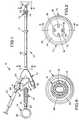
- Figure 1 is a side view of the retrogradecoronary sinus catheter of the invention;
- Figure 2 is a distal end view of the catheter offigure 1;
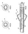
- Figure 3 is a longitudinal cross-sectional viewof a distal end portion of the catheter of figures 1 and 2taken substantially along line 3-3 in figure 2;
- Figure 4 is a cross-sectional view substantiallyalong line 4-4 of figure 1, illustrating a pressure-sensingtube portion;
- Figure 5 is a cross-sectional view similar tofigure 4 of the pressure-sensing tube portion,illustrating the cross section of the pressure-sensingtube portion when the balloon is drawn down by vacuum;
- Figure 6 is a cross-sectional view substantiallyalong line 6-6 of figure 1;
- Figure 7 is a longitudinal cross-sectional viewthrough the inflatable balloon shown in figures 1-2;
- Figure 8 is a longitudinal cross-sectional viewsimilar to figure 3 illustrating an alternative,autoinflating embodiment of the balloon catheter;
- Figure 9 is a longitudinal cross-sectional viewsimilar to figures 3 and 8 but further cut away,illustrating yet another alternative embodiment of theballoon catheter;
- Figure 10 shows the distal portion of anotherembodiment of the coronary sinus catheter; and
- Figure 11 shows the distal portion of yetanother embodiment of the coronary sinus catheter, similarin some respects to the catheter of figure 10.
- Now referring to the drawing, a coronary sinuscatheter assembly of the invention is indicated in itsentirety by the
reference numeral 10. The coronarysinuscatheter assembly 10 includes acoronary sinus catheter 12, amalleable stylet 14 and asyringe 15 for inflating aninflatable balloon 16 mounted on thecatheter 12.An adjustableannular suture ring 17 may be provided along thecatheter tube 18. Thecatheter 12 is amodified version of the catheter described in U.S. PatentNo. 4,927,412 (Menasche).Thecatheter 12 is particularly designed forthe retrograde infusion of cardioplegia solution into thecoronary sinus of a patient's heart. Thecatheter 12 isdesigned for use with either the "blind" or "open atrium"techniques. - As shown in figure 1, the
catheter 12 generallycomprises a flexible, elongate catheter tube 18 (e.g., 5.7mm OD (17French)) having proximal anddistal ends inflatable balloon 16 which is adapted for retaining thedistal end 22 of thecatheter 12 in the coronary sinus,and a pressure orinflation sensor tube 24 for sensingpressure in theballoon 16 to indicate the status of theballoon 16. The pressure orinflation sensor tube 24 hasan internal volume that is relatively non-expansiblerelative to the internal volume of theinflation balloon 16 in normal operation of thecatheter 12. - As used herein, "proximal" and "distal" refer toopposite directions along the
catheter 12. The "distal"direction is the direction (rightwardly in figure 1)toward theend 22 of thecatheter 12 that is inserted inthe coronary sinus. The "proximal" direction is thedirection (leftwardly in figure 1) toward theend 20 ofthecatheter 12 which is connected to other components,such as tubing leading from a heat exchanger for coolingcardioplegia solution (not shown), of an extracorporeal supportcircuit (also not shown). Cardioplegia solution beingdelivered to the coronary sinus flows in the "distal"direction through thecatheter 12. The proximal end ofthecatheter 12 will be indicated by thereference numeral 20. - The
catheter tube 18 includes infusion,pressure-sensing andinflation lumens catheter tube 18. Atleast one infusion lumen outlet, preferably fouroutlets distal end 22 of thecatheter tube 18. At least onepressure-sensing lumen outlet 40 is provided generallyadjacent thedistal end 22 of thecatheter tube 18. Oneend of thepressure sensor tube 24 is in fluidcommunication with the proximal end of theinflation lumen 30, which is the end opposite theinflation balloon 16. - The
catheter tube 18 is preferably formed ofsilicone rubber material, and is flexible and resilient.As an alternative, thecatheter tube 18 can be of thewire-reinforced type, which although it will be stifferthan the preferred version would still be flexible andresilient in normal use. - A three-way Y-
type connection assembly 41 ismounted on theproximal end 20 of thecatheter tube 18 toadapt thecatheter 12 for connecting (1) thesyringe 15 influid communication with the balloon-inflation lumen 30,(2) a cardioplegia supply line (not shown) in fluidcommunication with theinfusion lumen 26, and (3) apressure sensing line (not shown) in fluid communicationwith the pressure-sensing lumen 28 to monitor pressure inthe coronary sinus adjacent thedistal tip 72 of thecatheter 12. - The
connection assembly 41 is molded of siliconematerial and is bonded to thecatheter tube 18 by anysuitable technique including silicone adhesive, such asavailable under the trade designation "LOCTITE 18188" fromLoctite Corp., Newington, Connecticut. Thepressuresensor tube 24 may be an integral molded part of theconnection assembly 41. - The
inflatable balloon 16 is mounted on thecatheter tube 18 generally adjacent thedistal end 22 ofthecatheter tube 18 proximally (leftwardly in figure 1)of the infusion lumen and pressure-sensing lumen outlets inflation lumen 30is in fluid communication with the interior 42 of theballoon 16 for inflating theballoon 16. Theballoon 16has a generally pear-shaped cross-sectional profile alongthe longitudinal direction of thecatheter tube 18. - The
balloon 16 is molded of elastomericmaterial, such as silicone rubber, having a durometer inthe range of 20 to 35 on the Shore A scale, and has a wallthickness in the range of 0.3-0.5 millimeters when notinflated. Most preferably, theballoon 16 has a wallthickness when not inflated of approximately 0.33-0.48millimeters (e.g., 0.012-0.019 inches). For example, thewall thickness of theballoon 16 may be approximately0.43mm (0.017 inches), and the durometer is approximately28 on the Shore A scale. - Suitable silicone rubber material for the
balloon 16 includes a blend of the materials availableunder the trade designations "HE-26" and "HE-30" from DowCorning Corp., Midland, Michigan. Theballoon 16 may bemolded by using liquid injection molding (LIM), transfermolding or blow molding. - The
balloon 16 has a plurality of concentricoutwardly-facing spaced-apart parallel lands orribs 44for frictionally engaging the coronary sinus. Theballoon's normal, uninflated configuration is expandedoutwardly from thecatheter tube 18 such that thelongitudinal cross-sectional profile of theballoon 16 isgenerally pear-shaped. Theballoon 16 may be drawninwardly from its normal configuration when a vacuum isdrawn on theinflation lumen 30. Thepressure sensor tube 24 is adapted to provide an indication (among otherthings) of whether a vacuum has been drawn on theinflatable balloon 16. Figure 5 illustrates thepressuresensor tube 24 flattening out somewhat in response tovacuum. - As used herein, "vacuum" merely refers to thepressure in the
interior 42 of theballoon 16 being lessthan the outside ambient pressure or local environmentalpressure (e.g., pressure in the right atrium or coronarysinus). Normally, it is used to refer to the interiorpressure of theballoon 16 being sufficiently low that theballoon 16 is drawn toward thecatheter tube 18. - It is believed that drawing the
balloon 16inwardly toward thecatheter tube 18 facilitatesintroducing thedistal end 22 of thecatheter 12 into thecoronary sinus via the "blind" technique. In the "blind"technique, a small incision is made into the right atriumof the heart and thedistal end 22 of thecatheter 12 isintroduced into the coronary sinus "blind" via the rightatrium. In the "open atrium" technique as opposed to the"blind" technique, a large incision is made into the rightatrium to allow direct access of the coronary sinus. - The profile of the
balloon 16 includes asubstantially conicalproximal surface 46 taperinggradually down in the proximal direction (leftwardly infigure 1) to the surface of thecatheter tube 18, and adistal surface 48 tapering at a higher average slope downin the distal direction (rightwardly in figure 1) to thesurface of thecatheter tube 18 or the distal tip 50 ofthecatheter 12. Theballoon 16 is generally symmetricalaround the longitudinal axis of thecatheter tube 18. Theproximal surface 46 tapers downwardly at an included angleof approximately 50 degrees from the maximum radius of theballoon 16 to the surface of thecatheter tube 18. - As used herein, "included angle" refers to theangle formed between opposite sides of the conicalsurfaces, and is double the angle formed between theconical surface and the longitudinal axis of the
cathetertube 18. - The
distal surface 48 of theballoon 16 includestwo portions: (1) a first (conical or frustoconical)portion 52 extending distally from theproximal surface 46and tapering in the distal direction at an included angleof approximately 80 degrees; and (2) a second generallyflat portion 54 extending between the outercircumferential surface of thedistal tip 72 orcathetertube 18 adjacent thedistal tip 72. Theflat portion 54is generally perpendicular to the longitudinal axis of thecatheter tube 18. - The
annular ribs 44 are formed on theproximalsurface 46 and theconical portion 52 of thedistalsurface 48 of theballoon 16. As illustrated in figure 7,theribs 44A formed along theproximal surface 46 of theballoon 16 are asymmetrical. Theproximal ribs 44Ainclude generally annular,outer surface portions 56 thatare co-axial with the longitudinal axis of thecathetertube 18, andproximal surface portions 58 extendingoutwardly from theproximal surface 46 approximately at aright angle to theproximal surface 46 to the annular,outer surface portions 56. The juncture between theannular,outer surface portions 56 and theproximalsurface portions 58 has a suitable radius, such as 0.005inches (0.127mm). Most preferably, there are fiveribs 44A formed along theproximal surface 46 of theballoon 16,and the fiveribs 44A are spaced at approximately 0.07inch (1.78mm) intervals in the longitudinal direction ofthecatheter 12. - The
annular ribs 44B formed along theconicalportion 52 of the balloon'sdistal surface 48 arepreferably generally symmetrical through their crosssections. Theribs 44B extend from the surface of theconical portion 52 approximately 0.02 inches (0.508mm),and have a cross-sectional radius of approximately 0.03inches (0.762mm). - As shown in figure 7, the
balloon 16 is providedwith two annular glue rings 60 and 62 alongtubularextensions tubular extensions catheter tube 18. The even glue line is believed to helpstabilize theballoon 16 to maintain theballoon 16centered around thecatheter tube 18 as theballoon 16 isinflated. Suitable glue includes a silicone adhesiveavailable under trade designation "LOCTITE 18188" fromLoctite Corp., Newington, Connecticut, or the siliconeadhesive available under the trade designation "WALKER950". - The
pressure sensor tube 24 is formed ofelastomeric material having a durometer greater than 35 onthe Shore A scale, and having a wall thickness greaterthan 0.6 millimeters. Preferably, thepressure sensortube 24 has a durometer in the range of 35-50 on the ShoreA scale, and a wall thickness in the range of 0.6-1.3millimeters (0.025-0.05 inches). Most preferably, thepressure sensor tube 24 has durometer of 40 on the Shore Ascale, and a wall thickness of approximately 0.76-1.01millimeters (0.03-0.04 inches). For example, thepressuresensor tube 24 may have a wall thickness of 0.89millimeters (0.035 inches). - The
pressure sensor tube 24 may conveniently beformed of silicone rubber material available under thetrade designation "LSR 595" from Dow Corning Corp.,Midland, Michigan by liquid injection molding ("LIM"),transfer molding or extrusion. Thelumen 67 of thepressure sensor tube 24 may have a relaxed diameter (seefigure 4) of approximately 0.25 inches (6.4mm). - A
connection device 68 is provided at theproximal end 20 of thecatheter 12 in fluid communicationwith the proximal end of thepressure sensor tube 24,which is the end opposite theinflation lumen 30. Theconnection device 68 is adapted for connecting apressurizing means, such as thesyringe 15, to thecatheter 12 to inflate and/or deflate theinflatableballoon 16. - The
syringe 15 also permits a vacuum to be drawnon theballoon 16 as discussed above to draw theballoon 16 inwardly toward thecatheter tube 18. Thesyringe 15is preferably filled with saline solution, which is notcompressible, although air could also be used. It iscontemplated that the syringe would have an internalvolume of 3cc, and that up to 5cc of fluid volume could beintroduced into theballoon 16,inflation lumen 30 andpressure sensor tube 24. - A
valve 69 is provided between theconnectiondevice 68 and thepressure sensor tube 24. Thevalve 69 is designed to prevent flow or escape of fluid through thevalve 69, except when the male luer fitting of thesyringe 15 is inserted into theconnection device 68. When theluer fitting of thesyringe 15 is mounted in theconnection device 68, thevalve 69 opens to allow deliveryof fluid from thesyringe 15 to theballoon 16 orwithdrawal of fluid from theballoon 16 by drawing vacuumwith thesyringe 15. Thevalve 69 allows thesyringe 15to be withdrawn, with fluid being sealed in theballoon 16,inflation lumen 30 andpressure sensor tube 24. - According to the invention,the
infusion lumen 26 includes a constricted portion 70(figure 3) spaced from theinfusion lumen outlets constricted portion 70 of theinfusion lumen 26 so that fluid exiting theinfusion lumen outlets constricted portion 70 of theinfusion lumen 26. For example, the totalcross-sectional areas of theinfusion lumen outlets constricted portion 70 may beapproximately 1.8mm2; and the typical cross-sectional areaof the infusion lumen may be 3.25mm2. - Preferably, the molded
distal tip 72 is soft androunded-conical and has a closed end. As used herein,"rounded-conical" refers to a generally conical structurein which the surfaces may be smoothly rounded instead oftapering at a constant angle. The infusion lumenoutlets distal tip 72. Theelongate slots distal tip 72. The pressure-sensing lumen outlet 40 opensinto one of theelongate outlet slots 32. Thedistal tip 72 is conveniently molded of silicone rubber material having a durometer of approximately 50 on the Shore Ascale. - The
constricted portion 70 may be formed by areduced diameter tubular extension of the moldeddistaltip 72 extending into thecatheter tube 18. The insidediameter of theconstricted portion 70 may beapproximately 0.06 inches (1.52mm). The internal spaceformed between theinfusion lumen outlets constricted portion 70 preferably has a cross-sectionalarea greater than the cross-sectional area oftheconstricted portion 70. - In yet another preferred aspect of theinvention, a temperature sensing strip 74 (figure 1) isprovided along the
infusion lumen 26 generally adjacenttheproximal end 20 of thecatheter 12. Thetemperaturesensing strip 74 includes liquid crystal display means(also 74) on thecatheter 12 for displaying thetemperature of the fluid being infused. Preferably,duplicate display means 74 are provided along oppositesides of thecatheter 12. Temperature sensing strips ofsuitable type are available from American Thermometer Co.,Glenview, Illinois. It is believed that thetemperaturesensing strip 74 will be a significant convenience for thesurgeon, allowing direct reading of the temperature of thecardioplegia solution without looking away from thesurgical field. - The
temperature sensing strip 74 convenientlyhas an operating range between 4-40 degrees Celsius. Aplurality of indicia may be provided on thetemperaturesensing strip 74 to indicate various temperature points.The indicia on thestrip 74 may be of the type comprisinga plurality of small sections of temperature sensitivematerial arranged along thetemperature sensing strip 74which change color according to their temperature. - For example, seven sections corresponding totemperature values of 4, 7, 10, 13, 34, 37 and 40 degreesCelsius could be provided on each display means 74. Thesections corresponding to 4, 7, 10 and 13 degree Celsius values are framed by the color blue, and the sectionscorresponding to 34, 37 and 40 degrees are framed by thecolor red. If the temperature is exactly 10 degreesCelsius, the 10 degree Celsius section would turn a brightturquoise color. A straw color in that section wouldindicate a temperature slightly above the value displayedin that small section, and a royal blue color in thatsection would indicate a temperature slightly below thevalue displayed.
- A
suitable connection device 76 is provided ontheproximal end 20 of thetemperature sensing strip 74for connecting a cardioplegia supply line (not shown) influid communication with theinfusion lumen 26. Forexample, theconnection device 76 may comprise a suitablelocking female luer fitting 76. A similar connectiondevice 78 (e.g., a locking female luer fitting 78) may beprovided at the proximal end of the pressure-sensing lumen 28 for connecting a pressure sensing line (not shown) influid communication with the pressure-sensing lumen 28. - A
clamp 79, such as apinch clamp 79 ofconventional design, is provided on theconnectionassembly 41 along theinfusion lumen 26 between thecatheter tube 18 and thetemperature sensing strip 74.Theclamp 79 allows manual control of cardioplegiasolution flow through thecatheter 12, as well as manualclosing of theinfusion lumen 26 to stop delivery ofcardioplegia solution. - The
stylet 14 includes malleable wire, and isdeformable to set bends therein. Preferably, thestylet 14 is formed by coating the malleable wire with plasticmaterial. As shown in figure 1, aring 80 may be providedon the proximal end of thestylet 14 for grasping thestylet 14 with a finger, either for removal from thecatheter 12 or to facilitate manipulating thecatheterassembly 10 to insert thedistal end 22 of thecatheter 12into the coronary sinus. Thering 80 may be molded ofsuitable plastic resin material. - As illustrated in figure 8, an alternativecatheter designated generally 100 has at least oneballoon-inflating
opening 102 formed in thecatheter tube 104 between the interior 105 of theballoon 106 and theinfusion lumen 108. In this embodiment, aconstrictedportion 110, similar toconstricted portion 70, ispositioned along theinfusion lumen 108 between theballoon-inflatingopening 102 and theinfusion lumenoutlet 112. Theconstricted portion 110 is adapted tocreate back pressure in theinfusion lumen 108 toautomatically inflate theballoon 106 when fluid is beinginfused through thecatheter 100. Other features ofcatheter 100 are similar tocatheter 12 described above,with one exception being thatcatheter 100 lacks aseparate inflation lumen. - As illustrated in figure 9, a second alternativecatheter designated generally 200 has an
inflatableballoon 202 which lays flat against the outer surface ofthecatheter tube 204 when theballoon 202 is notinflated. Theballoon 202 is provided with a plurality(e.g., 4) of annular lands orribs 206 that are similar inmany respects toribs 44A ofballoon 16. Theribs 206 ofthis alternative embodiment are asymmetrical in a fashionsimilar toribs 44A. Other features ofcatheter 200 aresimilar tocatheter 12. - Figure 10 illustrates another embodiment of thecoronary sinus catheter of the invention, here designated300. The
coronary sinus catheter 300 includes aballoon 302 having a plurality of outwardly-facing, spaced-apart,segmented, parallel, annular ribs or lands generallyindicated at 304 for frictionally engaging the coronarysinus, but is otherwise similar to thecatheter 200 infigure 9. As an alternative, the segmented-rib ballooncatheter could be formed in the profile of figure 1, 3, 7and 8, and be of the type including a balloon-inflatingopening, similar to the embodiment of figure 8, thatallows infusion fluid to inflate theballoon 302. - The segmented ribs or lands are preferablyintegrally molded with the
balloon 302 of generallyelastomeric silicone material. Each segmented rib orland 304 comprises a plurality of solid raisedrib portions 306separated bynon-raised portions 308, with the raisedribportions 306 andnon-raised portions 308 extendingannularly around theballoon 302 in alternating fashion.The raisedrib portions 306 of adjacent ribs or lands 304are generally aligned along the longitudinal direction ofthecatheter 300, and thenon-raised portions 308 ofadjacent ribs or lands 304 are generally aligned along thelongitudinal direction of thecatheter 300. - The
balloon 302 preferable is expandable from anun-inflated diameter (Figure 10), generally equal to thediameter of the catheter tube and closely conforming tothe catheter tube, to an inflated diameter (not shown),substantially greater than the diameter of the cathetertube. Theballoon 302 is at its un-inflated diameter forintroducing thecatheter 300 into the coronary sinus, andis inflated to its inflated diameter to secure the distalend of thecatheter 300 in the coronary sinus. - Preferably, the
non-raised portions 308preferentially stretch in comparison to the raisedribportions 306 as theballoon 302 is inflated. Thearrangement is such as to reduce stretching and distortionof the raisedrib portions 306 to help them maintain, orreduce distortion from, their original profile as theballoon 302 is inflated. - Also, preferably, the raised
rib portions 306have a generally asymmetrical profile along thelongitudinal direction of thecatheter 300. The raisedrib portions 306 have anupper surface 310 slopingsmoothly and gradually forwardly to the surface of theballoon 302, and aback surface 312 extending from theupper surface 310 more steeply to the surface of theballoon 302 than theupper surface 310 slopes to thesurface of theballoon 302. - Most preferably, three to seven (e.g., six)segmented ribs or lands 304 are provided on the
balloon 302. Four segmented ribs or lands 304 are shown in figure10. Each segmented rib orland 304 has the same number ofraisedrib portions 306 andnon-raised portions 308 as theother ribs or lands 304. For example, each segmented riborland 304 may include eight raisedrib portions 306, andeightnon-raised portions 308. - Figure 10 also illustrates a pressure
sensinglumen outlet 314 extending out through the circumferenceof thecatheter 300 as opposed to into a infusion lumenoutlet as illustrated in figure 3. - Figure 11 illustrates yet another embodiment ofthe coronary sinus catheter, here designated 400, similarin many respects to
catheter 300 shown in figure 10. Likecatheter 300, thecoronary sinus catheter 400 comprises aballoon 402 having segmented ribs or lands 404 formed by aplurality of raisedrib portions 406 andnon-raisedportions 408 extending in alternating fashion around theperiphery of theballoon 402. In contrast tocatheter 300, the raisedrib portions 406 of adjacent ribs or lands404 are staggered such that the raisedrib portions 406are generally longitudinally aligned with thenon-raisedportions 408 of the adjacent rib orland 404. - To insert the
catheter 12 into the heart via the"blind" technique, the right atrium is sutured and thedistal end 22 of the catheter 12 (with thestylet 14therein) is inserted through a small incision (in the areadefined by the suture) into the right atrium. By placinga finger at the junction of the inferior vena cava and theatrio-ventricular groove, thedistal end 22 of thecatheter 12 can be guided into the coronary sinus. It maybe helpful to gently lift the diaphragmatic aspect of theright ventricle to unfold the coronary sinus. Theposition of thecatheter tip 72 can be verified bypalpating the tip. - The
balloon 16 should be inflated slowly withapproximately 3cc of saline solution, thestylet 14removed from thecatheter 12, and thepinch clamp 79closed. The suture can then be tightened and thecatheter 12 secured. Thepinch clamp 79 may then be opened, allair removed, and lines attached to theconnection device 76 for theinfusion lumen 26 and theconnection device 78for the pressure-sensing lumen 28. - Cardioplegia solution may then be infused intothe coronary sinus through the
catheter 12. The pressurein the coronary sinus should be carefully monitored. Dueto the deceleration of fluid after passing theconstrictedportion 70, flow through theinfusion lumen outlets temperature sensing strip 74 todetermine the temperature of the cardioplegia solution, orto verify information provided orally by the perfusionist. - As various changes could be made in the aboveconstructions without departing from the scope of theinvention, it is intended that all matter contained in thedescription above or shown in the accompanying drawingshall be interpreted as illustrative and not in a limitingsense.
Claims (10)
- A coronary sinus catheter (12; 100; 200; 300; 400) for the retrogradeinfusion of cardioplegia solution into the coronary sinus of a patient's heart, the catheter(12; 100; 200; 300; 400) comprising:characterized by the catheter comprising a constricted portion (70; 110) provided in theinfusion lumen (26; 108) generally adjacent the distal end (22) of the catheter tube (18;104) but spaced from the infusion lumen outlet (32, 34, 36, 38; 112), the total cross-sectionalarea of the infusion lumen outlet(s) (32, 34, 36, 38; 112) being substantiallygreater than the cross-sectional area of the constricted portion (70; 110) of the infusionlumen (26; 108) so that fluid exiting the infusion lumen outlet (32, 34, 36, 38; 112) isdecelerated relative to its velocity through the constricted portion (70; 110) of theinfusion lumen (26; 108).a flexible, elongate catheter tube (18; 104) having proximal and distalends (20, 22) and including infusion and pressure-sensing lumens (26, 28; 108)extending longitudinally through the tube (18; 104), at least one infusion lumen outlet(32, 34, 36, 38; 112) generally adjacent the distal end (22) of the catheter tube (18;104), and at least one pressure-sensing lumen outlet (40; 314) generally adjacent thedistal end (22) of the catheter tube (18; 104; 204);an inflatable balloon (16; 106; 202; 302; 402) on the catheter tube (18;104; 204) generally adjacent the distal end (22) of the catheter tube (18; 104; 204)proximally of the infusion lumen and pressure-sensing lumen outlets (32, 34, 36, 38,40; 112; 314) for securing the distal end (22) of the catheter (12; 100; 200; 300; 400) inthe coronary sinus; anda distal tip (72) on the distal end (22) of the catheter tube (18; 104; 204);
- A coronary sinus catheter (12; 200; 300; 400) according to claim 1furthercharacterized in that:the balloon (16) comprises a molded balloon (16) having two tubularextensions (64, 66) that are glued to the catheter tube (18) to mount the balloon (16) onthe catheter tube (18), the tubular extensions (64, 66) including annular ribs (60, 62)extending radially inwardly adjacent the expandable portion of the balloon (16) toprovide an even glue line adjacent the expandable portion of the balloon (16)the balloon (16; 202; 302; 402) has a wall thickness when not inflated ofapproximately 0.33-0.48 millimeters; andthe balloon (16) has a generally pear-shaped cross-sectional profilealong the longitudinal direction of the catheter tube (18).
- A coronary sinus catheter (12; 100; 200; 300; 400) according to anypreceding claim furthercharacterized in that the distal end (22) of the catheter tube (18;104; 204) comprises a rounded-conical distal tip (72) having a closed end, and theinfusion lumen outlet (32, 34, 36, 38; 112) comprises a plurality of elongate outlet slots(32, 34, 36, 38; 112) formed in the distal tip (72), the elongate slots (32, 34, 36, 38;112) being spaced approximately equally around the circumference of the distal tip(72).
- A coronary sinus catheter (12) according to any preceding claimfurthercharacterized in that a temperature sensing strip (74) is positioned along theinfusion lumen (26) generally adjacent the proximal end (20) of the catheter (12), thetemperature sensing strip (74) including display means (74) on the catheter (12) fordisplaying the temperature of the fluid being infused.
- A coronary sinus catheter (12) according to any preceding claimfurthercharacterized in that the balloon (16; 202; 302; 402) has a plurality ofoutwardly-facing, spaced-apart lands or ribs (44; 206; 304; 404) for frictionallyengaging the coronary sinus, the lands or ribs (44) being concentric and parallel.
- A coronary sinus catheter (300; 400) according to claim 5 furthercharacterized in that the plurality of outwardly-facing, spaced-apart annular lands orribs (304; 404) comprises segmented annular ribs or lands (304; 404), each segmentedannular rib or land (304; 404) comprising a plurality of raised rib portions (306; 406)separated by non-raised portions (308; 408) extending annularly around the peripheryof the balloon (302; 402) in alternating fashion.
- A coronary sinus catheter (400)according to claim 6 furthercharacterized in that the raised rib portions (406) of adjacent ribs or lands (404) arestaggered such that the raised rib portions (406) of one rib or land (404) are generallylongitudinally aligned with the non-raised portions (408) of the adjacent rib or land(404).
- A coronary sinus catheter (300) according to claim 6 furthercharacterized in that the raised rib portions (306) of adjacent ribs or lands (304) aregenerally aligned along the longitudinal direction of the catheter (300).
- A coronary sinus catheter (300; 400) according to any of claims 6-8furthercharacterized in that the raised rib portions (306; 406) are generally solid, thenon-raised portions (308; 408) preferentially stretching in comparison to the raised ribportions (306; 408) as the balloon (302; 402) is inflated, thereby reducing stretchingand distortion of the raised rib portions (306; 406) as the balloon (302; 402) is inflated.
- A coronary sinus catheter (100) according to any preceding claimfurthercharacterized in that at least one balloon-inflating opening (102) is formed in thecatheter tube (104) between the interior (105) of the balloon (106) and the infusionlumen (108), the constricted portion (110) being positioned along the infusion lumen(108) between the balloon-inflating opening (102) and the infusion lumen outlet (112)such that the constricted portion (110) is adapted to create back pressure in the infusionlumen (108) to inflate the balloon (106) when fluid is being infused through thecatheter (100).
Applications Claiming Priority (5)
| Application Number | Priority Date | Filing Date | Title |
|---|---|---|---|
| US874589 | 1992-04-27 | ||
| US07/874,589US5324260A (en) | 1992-04-27 | 1992-04-27 | Retrograde coronary sinus catheter |
| US21526 | 1993-02-23 | ||
| US08/021,526US5395331A (en) | 1992-04-27 | 1993-02-23 | Retrograde coronary sinus catheter having a ribbed balloon |
| EP93106754AEP0567976B1 (en) | 1992-04-27 | 1993-04-26 | Retrograde coronary sinus catheter |
Related Parent Applications (1)
| Application Number | Title | Priority Date | Filing Date |
|---|---|---|---|
| EP93106754ADivisionEP0567976B1 (en) | 1992-04-27 | 1993-04-26 | Retrograde coronary sinus catheter |
Publications (3)
| Publication Number | Publication Date |
|---|---|
| EP0841073A2 EP0841073A2 (en) | 1998-05-13 |
| EP0841073A3 EP0841073A3 (en) | 1998-10-21 |
| EP0841073B1true EP0841073B1 (en) | 2002-07-03 |
Family
ID=26694790
Family Applications (3)
| Application Number | Title | Priority Date | Filing Date |
|---|---|---|---|
| EP98100991AExpired - LifetimeEP0841073B1 (en) | 1992-04-27 | 1993-04-26 | Retrograde coronary sinus catheter |
| EP98103595AExpired - LifetimeEP0853954B1 (en) | 1992-04-27 | 1993-04-26 | Retrograde coronary sinus catheter |
| EP93106754AExpired - LifetimeEP0567976B1 (en) | 1992-04-27 | 1993-04-26 | Retrograde coronary sinus catheter |
Family Applications After (2)
| Application Number | Title | Priority Date | Filing Date |
|---|---|---|---|
| EP98103595AExpired - LifetimeEP0853954B1 (en) | 1992-04-27 | 1993-04-26 | Retrograde coronary sinus catheter |
| EP93106754AExpired - LifetimeEP0567976B1 (en) | 1992-04-27 | 1993-04-26 | Retrograde coronary sinus catheter |
Country Status (5)
| Country | Link |
|---|---|
| US (3) | US5395331A (en) |
| EP (3) | EP0841073B1 (en) |
| JP (1) | JPH0663148A (en) |
| CA (1) | CA2094900A1 (en) |
| DE (3) | DE69331644T2 (en) |
Cited By (2)
| Publication number | Priority date | Publication date | Assignee | Title |
|---|---|---|---|---|
| US6714806B2 (en) | 2000-09-20 | 2004-03-30 | Medtronic, Inc. | System and method for determining tissue contact of an implantable medical device within a body |
| US7887661B2 (en) | 2003-03-12 | 2011-02-15 | Advanced Cardiovascular Systems, Inc. | Infusion treatment agents, catheters, filter devices, and occlusion devices, and use thereof |
Families Citing this family (175)
| Publication number | Priority date | Publication date | Assignee | Title |
|---|---|---|---|---|
| US5769812A (en) | 1991-07-16 | 1998-06-23 | Heartport, Inc. | System for cardiac procedures |
| US5584803A (en) | 1991-07-16 | 1996-12-17 | Heartport, Inc. | System for cardiac procedures |
| US5558644A (en)* | 1991-07-16 | 1996-09-24 | Heartport, Inc. | Retrograde delivery catheter and method for inducing cardioplegic arrest |
| US6482171B1 (en) | 1991-07-16 | 2002-11-19 | Heartport, Inc. | Multi-lumen catheter |
| US5395331A (en)* | 1992-04-27 | 1995-03-07 | Minnesota Mining And Manufacturing Company | Retrograde coronary sinus catheter having a ribbed balloon |
| US5653690A (en)* | 1992-12-30 | 1997-08-05 | Medtronic, Inc. | Catheter having a balloon with retention enhancement |
| US5487730A (en)* | 1992-12-30 | 1996-01-30 | Medtronic, Inc. | Balloon catheter with balloon surface retention means |
| US5984909A (en)* | 1993-08-13 | 1999-11-16 | Daig Corporation | Coronary sinus catheter |
| US6001085A (en)* | 1993-08-13 | 1999-12-14 | Daig Corporation | Coronary sinus catheter |
| US5597377A (en)* | 1994-05-06 | 1997-01-28 | Trustees Of Boston University | Coronary sinus reperfusion catheter |
| US5478309A (en) | 1994-05-27 | 1995-12-26 | William P. Sweezer, Jr. | Catheter system and method for providing cardiopulmonary bypass pump support during heart surgery |
| US5695457A (en) | 1994-07-28 | 1997-12-09 | Heartport, Inc. | Cardioplegia catheter system |
| IT1272801B (en)* | 1994-09-02 | 1997-06-30 | Mauro Dimitri | SPECIFIC CATHETER FOR PERCUTANEOUS GASTROSTOMY |
| JPH08252327A (en)* | 1995-01-30 | 1996-10-01 | Minnesota Mining & Mfg Co <3M> | Switch which selectively makes fluid direct to two kinds of catheters |
| US5735817A (en)* | 1995-05-19 | 1998-04-07 | Shantha; T. R. | Apparatus for transsphenoidal stimulation of the pituitary gland and adjoining brain structures |
| US5645528A (en)* | 1995-06-06 | 1997-07-08 | Urologix, Inc. | Unitary tip and balloon for transurethral catheter |
| US5779685A (en)* | 1995-11-13 | 1998-07-14 | Quest Medical, Inc. | Retrograde cardioplegia catheter and method of use |
| US6048331A (en)* | 1996-05-14 | 2000-04-11 | Embol-X, Inc. | Cardioplegia occluder |
| AU3122197A (en)* | 1996-05-14 | 1997-12-05 | Embol-X, Inc. | Aortic occluder with associated filter and methods of use during cardiac surgery |
| US5954713A (en) | 1996-07-12 | 1999-09-21 | Newman; Fredric A. | Endarterectomy surgical instruments and procedure |
| US5904147A (en)* | 1996-08-16 | 1999-05-18 | University Of Massachusetts | Intravascular catheter and method of controlling hemorrhage during minimally invasive surgery |
| US6071271A (en)* | 1996-09-05 | 2000-06-06 | Baxter Research Medical, Inc. | Cardiopulmonary catheter system |
| US5755687A (en) | 1997-04-01 | 1998-05-26 | Heartport, Inc. | Methods and devices for occluding a patient's ascending aorta |
| US6068608A (en)* | 1997-05-01 | 2000-05-30 | Chase Medical, Inc. | Method of using integral aortic arch infusion clamp |
| US6132397A (en)* | 1997-05-01 | 2000-10-17 | Chase Medical Inc. | Integral aortic arch infusion clamp catheter |
| US6758854B1 (en) | 1997-05-09 | 2004-07-06 | St. Jude Medical | Splittable occlusion balloon sheath and process of use |
| WO1999004845A2 (en)* | 1997-07-22 | 1999-02-04 | Chase Medical Inc. | Catheter having a lumen occluding balloon and method of use thereof |
| US6241699B1 (en) | 1998-07-22 | 2001-06-05 | Chase Medical, Inc. | Catheter system and method for posterior epicardial revascularization and intracardiac surgery on a beating heart |
| DE19732965A1 (en)* | 1997-07-31 | 1999-02-18 | Knoerig Joachim Michael Dr | Balloon catheter |
| US5971967A (en) | 1997-08-19 | 1999-10-26 | Abbeymoor Medical, Inc. | Urethral device with anchoring system |
| US6340356B1 (en) | 1997-09-23 | 2002-01-22 | NAVIA JOSé ANTONIO | Intraluminal catheter with expandable tubular open-walled element |
| US6135981A (en)* | 1997-10-22 | 2000-10-24 | Dyke; Charles C. | Protective aortic occlusion catheter |
| AU1712599A (en)* | 1997-12-08 | 1999-06-28 | Cardeon Corporation | Aortic catheter and methods for inducing cardioplegic arrest and for selective aortic perfusion |
| US20030097138A1 (en)* | 1997-12-12 | 2003-05-22 | Boris Reydel | Body canal intrusion instrumentation having bi-directional coefficient of surface friction with body tissue |
| US6767339B2 (en) | 1997-12-12 | 2004-07-27 | Wilson-Cook Medical, Inc. | Body canal intrusion instrumentation having bidirectional coefficient of surface friction with body tissue |
| US6471717B1 (en)* | 1998-03-24 | 2002-10-29 | Innercool Therapies, Inc. | Selective organ cooling apparatus and method |
| US7371254B2 (en)* | 1998-01-23 | 2008-05-13 | Innercool Therapies, Inc. | Medical procedure |
| US6261312B1 (en)* | 1998-06-23 | 2001-07-17 | Innercool Therapies, Inc. | Inflatable catheter for selective organ heating and cooling and method of using the same |
| US6251129B1 (en) | 1998-03-24 | 2001-06-26 | Innercool Therapies, Inc. | Method for low temperature thrombolysis and low temperature thrombolytic agent with selective organ temperature control |
| US6238428B1 (en) | 1998-01-23 | 2001-05-29 | Innercool Therapies, Inc. | Selective organ cooling apparatus and method employing turbulence-inducing element with curved terminations |
| US6231595B1 (en)* | 1998-03-31 | 2001-05-15 | Innercool Therapies, Inc. | Circulating fluid hypothermia method and apparatus |
| US6096068A (en)* | 1998-01-23 | 2000-08-01 | Innercool Therapies, Inc. | Selective organ cooling catheter and method of using the same |
| US6719779B2 (en)* | 2000-11-07 | 2004-04-13 | Innercool Therapies, Inc. | Circulation set for temperature-controlled catheter and method of using the same |
| US6312452B1 (en) | 1998-01-23 | 2001-11-06 | Innercool Therapies, Inc. | Selective organ cooling catheter with guidewire apparatus and temperature-monitoring device |
| US6491716B2 (en) | 1998-03-24 | 2002-12-10 | Innercool Therapies, Inc. | Method and device for applications of selective organ cooling |
| US6245095B1 (en) | 1998-03-24 | 2001-06-12 | Innercool Therapies, Inc. | Method and apparatus for location and temperature specific drug action such as thrombolysis |
| US6491039B1 (en) | 1998-01-23 | 2002-12-10 | Innercool Therapies, Inc. | Medical procedure |
| US6251130B1 (en) | 1998-03-24 | 2001-06-26 | Innercool Therapies, Inc. | Device for applications of selective organ cooling |
| US6991645B2 (en)* | 1998-01-23 | 2006-01-31 | Innercool Therapies, Inc. | Patient temperature regulation method and apparatus |
| US6585752B2 (en)* | 1998-06-23 | 2003-07-01 | Innercool Therapies, Inc. | Fever regulation method and apparatus |
| US6051019A (en) | 1998-01-23 | 2000-04-18 | Del Mar Medical Technologies, Inc. | Selective organ hypothermia method and apparatus |
| US6379378B1 (en) | 2000-03-03 | 2002-04-30 | Innercool Therapies, Inc. | Lumen design for catheter |
| US6558412B2 (en) | 1998-01-23 | 2003-05-06 | Innercool Therapies, Inc. | Selective organ hypothermia method and apparatus |
| US6464716B1 (en) | 1998-01-23 | 2002-10-15 | Innercool Therapies, Inc. | Selective organ cooling apparatus and method |
| US6383210B1 (en)* | 2000-06-02 | 2002-05-07 | Innercool Therapies, Inc. | Method for determining the effective thermal mass of a body or organ using cooling catheter |
| US6159178A (en) | 1998-01-23 | 2000-12-12 | Heartport, Inc. | Methods and devices for occluding the ascending aorta and maintaining circulation of oxygenated blood in the patient when the patient's heart is arrested |
| US6254626B1 (en)* | 1998-03-24 | 2001-07-03 | Innercool Therapies, Inc. | Articulation device for selective organ cooling apparatus |
| US6843800B1 (en) | 1998-01-23 | 2005-01-18 | Innercool Therapies, Inc. | Patient temperature regulation method and apparatus |
| US6325818B1 (en) | 1999-10-07 | 2001-12-04 | Innercool Therapies, Inc. | Inflatable cooling apparatus for selective organ hypothermia |
| US7458984B2 (en)* | 1998-01-23 | 2008-12-02 | Innercool Therapies, Inc. | System and method for inducing hypothermia with active patient temperature control employing catheter-mounted temperature sensor and temperature projection algorithm |
| US6960222B2 (en)* | 1998-03-13 | 2005-11-01 | Gore Enterprise Holdins, Inc. | Catheter having a funnel-shaped occlusion balloon of uniform thickness and methods of manufacture |
| US20050131453A1 (en)* | 1998-03-13 | 2005-06-16 | Parodi Juan C. | Apparatus and methods for reducing embolization during treatment of carotid artery disease |
| US6179827B1 (en) | 1998-03-16 | 2001-01-30 | Chase Medical | Catheter having integral expandable/collapsible lumen |
| US6576002B2 (en) | 1998-03-24 | 2003-06-10 | Innercool Therapies, Inc. | Isolated selective organ cooling method and apparatus |
| US6599312B2 (en) | 1998-03-24 | 2003-07-29 | Innercool Therapies, Inc. | Isolated selective organ cooling apparatus |
| US6224624B1 (en) | 1998-03-24 | 2001-05-01 | Innercool Therapies, Inc. | Selective organ cooling apparatus and method |
| US6551349B2 (en) | 1998-03-24 | 2003-04-22 | Innercool Therapies, Inc. | Selective organ cooling apparatus |
| US6602276B2 (en)* | 1998-03-31 | 2003-08-05 | Innercool Therapies, Inc. | Method and device for performing cooling- or cryo-therapies for, e.g., angioplasty with reduced restenosis or pulmonary vein cell necrosis to inhibit atrial fibrillation |
| US7001378B2 (en)* | 1998-03-31 | 2006-02-21 | Innercool Therapies, Inc. | Method and device for performing cooling or cryo-therapies, for, e.g., angioplasty with reduced restenosis or pulmonary vein cell necrosis to inhibit atrial fibrillation employing tissue protection |
| US6905494B2 (en) | 1998-03-31 | 2005-06-14 | Innercool Therapies, Inc. | Method and device for performing cooling- or cryo-therapies for, e.g., angioplasty with reduced restenosis or pulmonary vein cell necrosis to inhibit atrial fibrillation employing tissue protection |
| US7291144B2 (en)* | 1998-03-31 | 2007-11-06 | Innercool Therapies, Inc. | Method and device for performing cooling- or cryo-therapies for, e.g., angioplasty with reduced restenosis or pulmonary vein cell necrosis to inhibit atrial fibrillation |
| US6685732B2 (en) | 1998-03-31 | 2004-02-03 | Innercool Therapies, Inc. | Method and device for performing cooling- or cryo-therapies for, e.g., angioplasty with reduced restenosis or pulmonary vein cell necrosis to inhibit atrial fibrillation employing microporous balloon |
| US6338727B1 (en) | 1998-08-13 | 2002-01-15 | Alsius Corporation | Indwelling heat exchange catheter and method of using same |
| US6908474B2 (en)* | 1998-05-13 | 2005-06-21 | Gore Enterprise Holdings, Inc. | Apparatus and methods for reducing embolization during treatment of carotid artery disease |
| US6869440B2 (en)* | 1999-02-09 | 2005-03-22 | Innercool Therapies, Inc. | Method and apparatus for patient temperature control employing administration of anti-shivering agents |
| US6830581B2 (en)* | 1999-02-09 | 2004-12-14 | Innercool Therspies, Inc. | Method and device for patient temperature control employing optimized rewarming |
| US6569145B1 (en) | 1999-03-25 | 2003-05-27 | Transvascular, Inc. | Pressure-controlled continuous coronary sinus occlusion device and methods of use |
| US7416554B2 (en) | 2002-12-11 | 2008-08-26 | Usgi Medical Inc | Apparatus and methods for forming and securing gastrointestinal tissue folds |
| US6238404B1 (en)* | 1999-09-16 | 2001-05-29 | Benito Hidalgo | Multipurpose medical device |
| US6500145B1 (en) | 2000-02-08 | 2002-12-31 | California Medical Laboratories, Inc. | Retrograde cardioplegia catheter |
| US6514226B1 (en) | 2000-02-10 | 2003-02-04 | Chf Solutions, Inc. | Method and apparatus for treatment of congestive heart failure by improving perfusion of the kidney |
| IL153753A0 (en)* | 2002-12-30 | 2003-07-06 | Neovasc Medical Ltd | Varying-diameter vascular implant and balloon |
| US6648906B2 (en) | 2000-04-06 | 2003-11-18 | Innercool Therapies, Inc. | Method and apparatus for regulating patient temperature by irrigating the bladder with a fluid |
| US6726708B2 (en) | 2000-06-14 | 2004-04-27 | Innercool Therapies, Inc. | Therapeutic heating and cooling via temperature management of a colon-inserted balloon |
| US6663589B1 (en)* | 2000-06-20 | 2003-12-16 | Haim Halevy | Catheter system |
| US6942680B2 (en)* | 2000-07-24 | 2005-09-13 | Jeffrey Grayzel | Stiffened balloon catheter for dilatation and stenting |
| US6719723B2 (en)* | 2000-12-06 | 2004-04-13 | Innercool Therapies, Inc. | Multipurpose catheter assembly |
| US6554819B2 (en) | 2001-01-09 | 2003-04-29 | Mount Sinai School Of Medicine Of New York University | Method and device for preventing contrast associated nephropathy |
| US6450987B1 (en) | 2001-02-01 | 2002-09-17 | Innercool Therapies, Inc. | Collapsible guidewire lumen |
| US20020111662A1 (en)* | 2001-02-09 | 2002-08-15 | Iaizzo Paul A. | System and method for placing an implantable medical device within a body |
| US6783511B2 (en) | 2001-04-12 | 2004-08-31 | Heartport, Inc. | Methods and devices for occluding a patient's ascending aorta and delivering oxygenated blood to the patient |
| US6682499B2 (en) | 2001-06-28 | 2004-01-27 | Jay Alan Lenker | Method and apparatus for venous drainage and retrograde coronary perfusion |
| US6562062B2 (en)* | 2001-08-10 | 2003-05-13 | Scimed Life Systems, Inc. | Balloon anchoring system |
| WO2003015672A1 (en)* | 2001-08-15 | 2003-02-27 | Innercool Therapies, Inc. | Method and apparatus for patient temperature control employing administration of anti-shivering |
| US6970747B2 (en) | 2002-01-11 | 2005-11-29 | Kokones Scott B | Neurostimulation lead stylet handle |
| US6736822B2 (en)* | 2002-02-20 | 2004-05-18 | Mcclellan Scott B. | Device and method for internal ligation of tubular structures |
| US20030163115A1 (en)* | 2002-02-26 | 2003-08-28 | Gershowitz Arthur D. | Retrograde cannula having automatically inflatable balloon |
| US6913597B2 (en)* | 2002-02-26 | 2005-07-05 | Terumo Cardiovascular Systems | Retrograde cannula preventing blood back-flow during stylet removal |
| US20040024362A1 (en)* | 2002-04-11 | 2004-02-05 | Hugh Trout | Stabilizing surgical delivery apparatus and method of use |
| DE10243335A1 (en)* | 2002-09-18 | 2004-04-08 | Schubert, Werner, Dr.med. | Apparatus to increase perfusion through heart muscle tissue, in the treatment of heart disease, has an underpressure catheter inserted into a major heart vein |
| US6976979B2 (en) | 2002-10-31 | 2005-12-20 | Medtronic, Inc. | Malleable cannula |
| US20040092844A1 (en)* | 2002-11-12 | 2004-05-13 | Johnson Eric T. | Guide catheter |
| US7763043B2 (en)* | 2003-01-09 | 2010-07-27 | Boston Scientific Scimed, Inc. | Dilatation catheter with enhanced distal end for crossing occluded lesions |
| US7250041B2 (en)* | 2003-03-12 | 2007-07-31 | Abbott Cardiovascular Systems Inc. | Retrograde pressure regulated infusion |
| US20080071250A1 (en)* | 2003-04-03 | 2008-03-20 | Crisp William E | Urinary tract catheter |
| US20040199086A1 (en)* | 2003-04-03 | 2004-10-07 | Crisp William E. | Urinary tract catheter |
| US7008438B2 (en)* | 2003-07-14 | 2006-03-07 | Scimed Life Systems, Inc. | Anchored PTCA balloon |
| US20050038381A1 (en)* | 2003-08-11 | 2005-02-17 | Kimberly-Clark Worldwide, Inc. | Catheter having a balloon member recessedly attached thereto |
| WO2005027995A2 (en)* | 2003-09-19 | 2005-03-31 | The Trustees Of The University Of Pennsylvania | Global myocardial perfusion catheter |
| US20050107820A1 (en) | 2003-11-13 | 2005-05-19 | Forsberg Andrew T. | Vascular puncture depth locator |
| US7429259B2 (en)* | 2003-12-02 | 2008-09-30 | Cadeddu Jeffrey A | Surgical anchor and system |
| US7273471B1 (en) | 2003-12-23 | 2007-09-25 | Advanced Cardiovascular Systems, Inc. | Catheter balloon having a porous layer with ridges |
| US7918869B2 (en)* | 2004-05-07 | 2011-04-05 | Usgi Medical, Inc. | Methods and apparatus for performing endoluminal gastroplasty |
| US7678081B2 (en)* | 2004-07-12 | 2010-03-16 | Pacesetter, Inc. | Methods and devices for transseptal access |
| US20060136023A1 (en)* | 2004-08-26 | 2006-06-22 | Dobak John D Iii | Method and apparatus for patient temperature control employing administration of anti-shivering agents |
| US20060079787A1 (en)* | 2004-09-30 | 2006-04-13 | Whiting James S | Transmembrane access systems and methods |
| US20070083168A1 (en)* | 2004-09-30 | 2007-04-12 | Whiting James S | Transmembrane access systems and methods |
| US8029470B2 (en)* | 2004-09-30 | 2011-10-04 | Pacesetter, Inc. | Transmembrane access systems and methods |
| US8945095B2 (en)* | 2005-03-30 | 2015-02-03 | Intuitive Surgical Operations, Inc. | Force and torque sensing for surgical instruments |
| US8375808B2 (en) | 2005-12-30 | 2013-02-19 | Intuitive Surgical Operations, Inc. | Force sensing for surgical instruments |
| US20070005011A1 (en)* | 2005-06-20 | 2007-01-04 | Boston Scientific Scimed, Inc. | Method, system, apparatus, and kit for remote therapeutic delivery |
| US20070010780A1 (en)* | 2005-06-27 | 2007-01-11 | Venkataramana Vijay | Methods of implanting an aorto-coronary sinus shunt for myocardial revascularization |
| US20070010781A1 (en)* | 2005-06-27 | 2007-01-11 | Venkataramana Vijay | Implantable aorto-coronary sinus shunt for myocardial revascularization |
| US8628518B2 (en) | 2005-12-30 | 2014-01-14 | Intuitive Surgical Operations, Inc. | Wireless force sensor on a distal portion of a surgical instrument and method |
| US7747334B2 (en)* | 2006-03-23 | 2010-06-29 | Cardiac Pacemakers, Inc. | Left ventricular lead shapes |
| JP2009535161A (en)* | 2006-04-29 | 2009-10-01 | ボード・オブ・リージエンツ,ザ・ユニバーシテイ・オブ・テキサス・システム | Device for use in transmural and intraluminal surgery |
| JP4262733B2 (en)* | 2006-08-08 | 2009-05-13 | 富士システムズ株式会社 | Medical balloon catheter |
| CA2916746C (en)* | 2006-10-17 | 2018-11-27 | C.R. Bard, Inc. | Waste management system |
| US8777912B2 (en)* | 2007-07-22 | 2014-07-15 | C. R. Bard, Inc. | Waste management system |
| US20090112238A1 (en)* | 2007-10-26 | 2009-04-30 | Vance Products Inc., D/B/A Cook Urological Inc. | Fistula brush device |
| WO2010094033A2 (en)* | 2009-02-13 | 2010-08-19 | Personics Holdings Inc. | Earplug and pumping systems |
| US20100286593A1 (en)* | 2009-05-11 | 2010-11-11 | Hotspur Technologies, Inc. | Balloon catheter with cutting features and methods for use |
| US10172669B2 (en) | 2009-10-09 | 2019-01-08 | Ethicon Llc | Surgical instrument comprising an energy trigger lockout |
| US9339291B2 (en)* | 2009-12-29 | 2016-05-17 | Cook Medical Technologies Llc | Cutting or scoring balloon, system and method of making a cutting or scoring balloon |
| EP2566562A1 (en) | 2010-05-07 | 2013-03-13 | Cook Medical Technologies LLC | Balloon with integral segmented dilation elements |
| GB2480498A (en) | 2010-05-21 | 2011-11-23 | Ethicon Endo Surgery Inc | Medical device comprising RF circuitry |
| EP2389974B1 (en)* | 2010-05-25 | 2014-04-23 | Miracor Medical Systems GmbH | A balloon catheter for introduction into a body vessel, in particular the coronary sinus |
| GB2484952B (en) | 2010-10-27 | 2012-09-26 | Cook Medical Technologies Llc | Valvuloplasty balloon catheter |
| US9987042B2 (en) | 2011-04-07 | 2018-06-05 | Jai Singh | General uterine manipulator and system |
| US20130197536A1 (en)* | 2011-04-07 | 2013-08-01 | Jai Singh | General uterine manipulator and system |
| CN203647441U (en) | 2011-04-07 | 2014-06-18 | 基万·史蒂文·辛格 | Uterine Manipulator System |
| KR101256908B1 (en)* | 2011-04-28 | 2013-04-23 | (주)에이치비메디컬스 | Filler for Eliminating Wrinkles |
| US8574221B2 (en) | 2011-09-09 | 2013-11-05 | Cook Medical Technologies Llc | Tubular medical device |
| US9333025B2 (en) | 2011-10-24 | 2016-05-10 | Ethicon Endo-Surgery, Llc | Battery initialization clip |
| AU2013249076B2 (en) | 2012-04-20 | 2018-03-29 | Jai Singh | Repositionable medical instrument support systems, devices, and methods |
| US10413240B2 (en) | 2014-12-10 | 2019-09-17 | Staton Techiya, Llc | Membrane and balloon systems and designs for conduits |
| US10159524B2 (en) | 2014-12-22 | 2018-12-25 | Ethicon Llc | High power battery powered RF amplifier topology |
| US10322269B1 (en)* | 2015-01-19 | 2019-06-18 | Dalent, LLC | Dilator device |
| US10314638B2 (en) | 2015-04-07 | 2019-06-11 | Ethicon Llc | Articulating radio frequency (RF) tissue seal with articulating state sensing |
| KR20180038052A (en)* | 2015-09-04 | 2018-04-13 | 더 리젠츠 오브 더 유니버시티 오브 미시간 | Device for assisting arterial microvascular anastomosis |
| US10959771B2 (en) | 2015-10-16 | 2021-03-30 | Ethicon Llc | Suction and irrigation sealing grasper |
| US10959806B2 (en) | 2015-12-30 | 2021-03-30 | Ethicon Llc | Energized medical device with reusable handle |
| US11458282B2 (en)* | 2016-02-04 | 2022-10-04 | Patient Shield Concepts, Llc | Catheter assembly with distinct inflation and drug delivery channels and overlapping balloon layers |
| US10856934B2 (en) | 2016-04-29 | 2020-12-08 | Ethicon Llc | Electrosurgical instrument with electrically conductive gap setting and tissue engaging members |
| US10987156B2 (en) | 2016-04-29 | 2021-04-27 | Ethicon Llc | Electrosurgical instrument with electrically conductive gap setting member and electrically insulative tissue engaging members |
| US10751117B2 (en) | 2016-09-23 | 2020-08-25 | Ethicon Llc | Electrosurgical instrument with fluid diverter |
| US11033325B2 (en) | 2017-02-16 | 2021-06-15 | Cilag Gmbh International | Electrosurgical instrument with telescoping suction port and debris cleaner |
| US10799284B2 (en) | 2017-03-15 | 2020-10-13 | Ethicon Llc | Electrosurgical instrument with textured jaws |
| US11497546B2 (en) | 2017-03-31 | 2022-11-15 | Cilag Gmbh International | Area ratios of patterned coatings on RF electrodes to reduce sticking |
| US10603117B2 (en) | 2017-06-28 | 2020-03-31 | Ethicon Llc | Articulation state detection mechanisms |
| PL3664706T3 (en)* | 2017-08-10 | 2022-02-14 | Vipun Medical Nv | Apparatus for measuring pressure changes in stomach |
| US11478316B2 (en)* | 2017-09-20 | 2022-10-25 | Shanghai Microport Medbot (Group) Co., Ltd. | Surgical robot system |
| US11484358B2 (en) | 2017-09-29 | 2022-11-01 | Cilag Gmbh International | Flexible electrosurgical instrument |
| US11033323B2 (en) | 2017-09-29 | 2021-06-15 | Cilag Gmbh International | Systems and methods for managing fluid and suction in electrosurgical systems |
| US11490951B2 (en) | 2017-09-29 | 2022-11-08 | Cilag Gmbh International | Saline contact with electrodes |
| US20190142403A1 (en) | 2017-11-16 | 2019-05-16 | M-V Arterica AB | Tissue closure device |
| US11179145B2 (en) | 2017-11-16 | 2021-11-23 | M-V Arterica AB | Collapsible tube for hemostasis |
| IT201800006185A1 (en)* | 2018-06-11 | 2019-12-11 | INSTRUMENT FITTED WITH CONTACT FORCE SENSOR | |
| EP3870076A4 (en) | 2018-10-24 | 2022-08-10 | Arterica Inc. | SELF-EXPANDING HEMOSTATIC DEVICES AND METHODS FOR FASCIAL AND VASCULAR PASSAGES |
| CN109692067B (en)* | 2019-01-04 | 2021-07-23 | 周树娟 | Gynecological ring taking instrument |
| USD877325S1 (en) | 2019-06-06 | 2020-03-03 | Dalent, LLC | Inflatable therapeutic treatment balloon device |
| EP4061244A4 (en)* | 2019-11-19 | 2024-06-19 | Arterica Inc. | VASCULAR CLOSURE DEVICES AND METHODS |
| KR102274006B1 (en)* | 2020-08-12 | 2021-07-08 | 주식회사 웨트러스트 | Drug injection module including a Slip auxiliary unit |
| KR102451958B1 (en)* | 2020-12-22 | 2022-10-11 | 재단법인 오송첨단의료산업진흥재단 | Non-contact pressure measuring system for balloon catheter and method for measuring pressure using the same |
| US11957342B2 (en) | 2021-11-01 | 2024-04-16 | Cilag Gmbh International | Devices, systems, and methods for detecting tissue and foreign objects during a surgical operation |
Family Cites Families (115)
| Publication number | Priority date | Publication date | Assignee | Title |
|---|---|---|---|---|
| US735400A (en)* | 1903-04-22 | 1903-08-04 | Richard P Mccully | Surgical instrument. |
| US1049087A (en)* | 1911-04-22 | 1912-12-31 | Charles H Hill | Non-slipping sole. |
| US1190179A (en)* | 1915-10-15 | 1916-07-04 | Edward L Livingston | Bath-mat. |
| US1289106A (en)* | 1916-10-24 | 1918-12-31 | Converse Rubber Shoe Company | Sole. |
| US2308484A (en)* | 1939-01-16 | 1943-01-19 | Davol Rubber Co | Catheter |
| US2393003A (en)* | 1944-05-03 | 1946-01-15 | Smith Minton Larkin | Kidney catheter |
| US2701559A (en)* | 1951-08-02 | 1955-02-08 | William A Cooper | Apparatus for exfoliating and collecting diagnostic material from inner walls of hollow viscera |
| US2854982A (en)* | 1958-01-22 | 1958-10-07 | Vito V Pagano | Nasopharyngeal tube |
| US2927584A (en)* | 1958-04-16 | 1960-03-08 | American Cystoscope Makers Inc | Means for anchoring a surgical device and a surgical drain embodying the same |
| US2983512A (en)* | 1958-08-20 | 1961-05-09 | Olin Mathieson | Ball bat |
| US3344791A (en)* | 1965-02-12 | 1967-10-03 | John W Foderick | Bulbous urinary catheter with axial extension means |
| US3385300A (en)* | 1965-08-10 | 1968-05-28 | Holter Company | Cervical cannula |
| US3521620A (en)* | 1967-10-30 | 1970-07-28 | William A Cook | Vascular coil spring guide with bendable tip |
| US3635223A (en)* | 1969-12-02 | 1972-01-18 | Us Catheter & Instr Corp | Embolectomy catheter |
| US3726269A (en)* | 1971-11-24 | 1973-04-10 | W Webster | Cardiovascular catheter for thermal dilution measurement |
| US3815608A (en)* | 1972-03-10 | 1974-06-11 | East West Med Prod | Retaining catheter |
| US3837347A (en)* | 1972-04-20 | 1974-09-24 | Electro Catheter Corp | Inflatable balloon-type pacing probe |
| AU5722173A (en)* | 1972-07-04 | 1975-01-09 | Stanley Francis Duturbure | Catheter tube |
| US3802440A (en)* | 1972-12-19 | 1974-04-09 | M Salem | Intubation guide |
| US3813729A (en)* | 1973-01-04 | 1974-06-04 | M Szabo | Rigid substantially u-shaped handle with closed-cell foam handgrip |
| US4210478A (en)* | 1973-05-08 | 1980-07-01 | International Paper Company | Method of making a catheter |
| US3867945A (en)* | 1973-05-14 | 1975-02-25 | Wendell M Long | Catheter stylets |
| US3854473A (en)* | 1973-05-29 | 1974-12-17 | Olympus Optical Co | Stilet for endoscopes |
| US3895637A (en)* | 1973-10-19 | 1975-07-22 | Daniel S J Choy | Self propelled conduit traversing device |
| US3957055A (en)* | 1974-09-23 | 1976-05-18 | Linder Gerald S | Catheter guide |
| US3970090A (en)* | 1975-02-03 | 1976-07-20 | Physio Medics, Inc. | Catheter |
| US4019515A (en)* | 1975-12-08 | 1977-04-26 | Daniel Kornblum | Enemata administering device |
| US4215703A (en)* | 1978-08-29 | 1980-08-05 | Willson James K V | Variable stiffness guide wire |
| FR2434628A1 (en)* | 1978-09-01 | 1980-03-28 | Durand Alain | BALLOON CATHETER |
| US4273131A (en)* | 1979-06-18 | 1981-06-16 | Auburn Enterprises, Inc. | Surgical stylet |
| US4304239A (en)* | 1980-03-07 | 1981-12-08 | The Kendall Company | Esophageal probe with balloon electrode |
| US4328806A (en)* | 1980-06-18 | 1982-05-11 | American Hospital Supply Corporation | Catheter with trans-luminal gas pathway |
| US4351341A (en)* | 1980-08-15 | 1982-09-28 | Uresil Company | Balloon catheter |
| US4413989A (en)* | 1980-09-08 | 1983-11-08 | Angiomedics Corporation | Expandable occlusion apparatus |
| US4531936A (en)* | 1981-01-29 | 1985-07-30 | Gordon Robert T | Device and method for the selective delivery of drugs to the myocardium |
| FR2502499B1 (en)* | 1981-03-27 | 1987-01-23 | Farcot Jean Christian | APPARATUS FOR BLOOD RETROPERFUSION, IN PARTICULAR FOR THE TREATMENT OF INFARCTUS BY INJECTION OF ARTERIAL BLOOD INTO THE CORONARY SINUS |
| US4456000A (en)* | 1981-08-17 | 1984-06-26 | Angiomedics Corporation | Expandable occlusion apparatus |
| EP0102352A1 (en)* | 1982-03-12 | 1984-03-14 | WEBSTER, Wilton W.Jr. | Autoinflatable catheter |
| US4545390A (en)* | 1982-09-22 | 1985-10-08 | C. R. Bard, Inc. | Steerable guide wire for balloon dilatation procedure |
| US4456017A (en)* | 1982-11-22 | 1984-06-26 | Cordis Corporation | Coil spring guide with deflectable tip |
| US4465072A (en)* | 1983-02-22 | 1984-08-14 | Taheri Syde A | Needle catheter |
| US4552558A (en)* | 1983-07-14 | 1985-11-12 | Rudolph Muto | Pressure warning, indicating and applying monitor for cuff type indwelling devices |
| DE3326648C2 (en)* | 1983-07-23 | 1986-02-27 | Werner Dr.med. 4330 Mülheim Schubert | Balloon catheter |
| CA1232814A (en)* | 1983-09-16 | 1988-02-16 | Hidetoshi Sakamoto | Guide wire for catheter |
| US5033998A (en)* | 1984-01-20 | 1991-07-23 | Eliot Corday | Retrograde delivery of pharmacologic and diagnostic agents via venous circulation |
| US4689041A (en)* | 1984-01-20 | 1987-08-25 | Eliot Corday | Retrograde delivery of pharmacologic and diagnostic agents via venous circulation |
| ZA85332B (en)* | 1984-01-20 | 1985-09-25 | Cedars Sinai Medical Center | Method of treatment of the myocardium and catheter for retroinfusion of pharmacologic agents |
| US4934996A (en)* | 1984-02-27 | 1990-06-19 | Boston Scientific Corporation | Pressure-controlled intermittent coronary sinus occlusion apparatus and method |
| US4529400A (en)* | 1984-03-23 | 1985-07-16 | Scholten James R | Apparatus for naso and oroendotracheal intubation |
| US4610661A (en)* | 1984-06-13 | 1986-09-09 | Possis Medical, Incorporated | Perfusion device |
| US4648384A (en)* | 1984-11-21 | 1987-03-10 | Schmukler Robert E | Retrograde coronary sinus perfusion device and method |
| US4632668A (en)* | 1984-12-31 | 1986-12-30 | University Of Virginia Alumni Patents Foundation | Ventricular catheter |
| FR2577424B1 (en)* | 1985-02-20 | 1989-04-28 | Gilles Karcher | CORONARY PERFUSION PUMP |
| US4619274A (en)* | 1985-04-18 | 1986-10-28 | Advanced Cardiovascular Systems, Inc. | Torsional guide wire with attenuated diameter |
| DE3519626A1 (en)* | 1985-05-31 | 1986-12-04 | Stöckert Instrumente GmbH, 8000 München | BALLOON CATHETER |
| US4931330A (en)* | 1985-07-03 | 1990-06-05 | Stier Sam S | Prefabricated, slip-resistant surface coating |
| US4682607A (en)* | 1985-12-02 | 1987-07-28 | Vlv Associates | Wire guide |
| US4646742A (en)* | 1986-01-27 | 1987-03-03 | Angiomedics Incorporated | Angioplasty catheter assembly |
| US4834709A (en)* | 1986-03-26 | 1989-05-30 | Sherwood Medical Company | Preformable catheter |
| US4721109A (en)* | 1986-04-08 | 1988-01-26 | Healey Maureen A | Temporary anastomotic device |
| US4676249A (en)* | 1986-05-19 | 1987-06-30 | Cordis Corporation | Multi-mode guidewire |
| EP0249338A3 (en)* | 1986-06-12 | 1988-12-14 | C.R. Bard, Inc. | Retroperfusion catheter |
| US4753637A (en)* | 1986-07-16 | 1988-06-28 | The John Hopkins University | Catheter having means for controlling the insertion depth |
| US4713049A (en)* | 1986-08-05 | 1987-12-15 | Medical Engineering Corporation | Ureteral stent kit |
| SE8603511D0 (en)* | 1986-08-20 | 1986-08-20 | * Andersson Ingvar | DEVICE FOR INSTITUTION OF LIQUIDS IN AN ORIGINAL |
| FR2607706B1 (en)* | 1986-12-05 | 1997-01-17 | Lefebvre Jean Marie | PERCUTANEOUS VASCULAR SHUTTERING DEVICE FOR DRUG INFUSIONS AND PERCUTANEOUS VASCULAR SHUTTERING METHOD USING THE SAME |
| US4782834A (en)* | 1987-01-06 | 1988-11-08 | Advanced Cardiovascular Systems, Inc. | Dual lumen dilatation catheter and method of manufacturing the same |
| US4762130A (en)* | 1987-01-15 | 1988-08-09 | Thomas J. Fogarty | Catheter with corkscrew-like balloon |
| US5024668A (en)* | 1987-01-20 | 1991-06-18 | Rocky Mountain Research, Inc. | Retrograde perfusion system, components and method |
| IT1203503B (en)* | 1987-02-25 | 1989-02-15 | Cardiosistemi Spa | VENOUS DRAINAGE CANNULA |
| US4863441A (en)* | 1987-07-17 | 1989-09-05 | Minnesota Mining And Manufacturing Company | Venous return catheter |
| ES2053591T3 (en)* | 1987-08-17 | 1994-08-01 | Braun Melsungen Ag | DOUBLE THERMISTOR THERMODILUTION CATHETER. |
| US4863430A (en)* | 1987-08-26 | 1989-09-05 | Surgical Dynamics, Inc. | Introduction set with flexible trocar with curved cannula |
| US4808165A (en)* | 1987-09-03 | 1989-02-28 | Carr Ann M | Inflation/deflation device for balloon catheter |
| US4850969A (en)* | 1987-10-01 | 1989-07-25 | Retroperfusion Systems, Inc. | Retroperfusion catheter and tip construction for use therewith |
| GB8800447D0 (en)* | 1988-01-09 | 1988-02-10 | Smiths Industries Plc | Inflation indicators for cuffed tubes |
| US4846186A (en)* | 1988-01-12 | 1989-07-11 | Cordis Corporation | Flexible guidewire |
| US5423745A (en)* | 1988-04-28 | 1995-06-13 | Research Medical, Inc. | Irregular surface balloon catheters for body passageways and methods of use |
| US5021045A (en)* | 1988-04-28 | 1991-06-04 | Research Medical, Inc. | Retrograde venous cardioplegia catheters and methods of use and manufacture |
| US5226427A (en)* | 1988-04-28 | 1993-07-13 | Research Medical Inc. | Removable stylet for retrograde cardioplegia catheter and methods for use |
| US5021046A (en)* | 1988-08-10 | 1991-06-04 | Utah Medical Products, Inc. | Medical pressure sensing and display system |
| US5001825A (en)* | 1988-11-03 | 1991-03-26 | Cordis Corporation | Catheter guidewire fabrication method |
| US4927412A (en)* | 1988-12-08 | 1990-05-22 | Retroperfusion Systems, Inc. | Coronary sinus catheter |
| US4886067A (en)* | 1989-01-03 | 1989-12-12 | C. R. Bard, Inc. | Steerable guidewire with soft adjustable tip |
| US5091205A (en)* | 1989-01-17 | 1992-02-25 | Union Carbide Chemicals & Plastics Technology Corporation | Hydrophilic lubricious coatings |
| US5007434A (en)* | 1989-02-07 | 1991-04-16 | Advanced Cardiovascular Systems, Inc. | Catheter tip attitude controlling guide wire |
| JP2545981B2 (en)* | 1989-05-09 | 1996-10-23 | 東レ株式会社 | Balloon catheter |
| US5031613A (en)* | 1989-06-07 | 1991-07-16 | JoAnne Hahn | Nebulizing catheter |
| US5045072A (en)* | 1989-06-13 | 1991-09-03 | Cordis Corporation | Catheter having highly radiopaque, flexible tip |
| HU212760B (en)* | 1989-06-20 | 1997-02-28 | Denes | Method and device for the apportion of chemical materials into the vein wall |
| US5047018A (en)* | 1989-08-14 | 1991-09-10 | Minnesota Mining And Manufacturing Company | Catheter and stylet assembly having dual position stylet |
| US5163912A (en)* | 1989-08-14 | 1992-11-17 | Minnesota Mining And Manufacturing Company | Catheter and stylet assembly having dual position stylet |
| US5180368A (en)* | 1989-09-08 | 1993-01-19 | Advanced Cardiovascular Systems, Inc. | Rapidly exchangeable and expandable cage catheter for repairing damaged blood vessels |
| US5034001A (en)* | 1989-09-08 | 1991-07-23 | Advanced Cardiovascular Systems, Inc. | Method of repairing a damaged blood vessel with an expandable cage catheter |
| DE3931350A1 (en)* | 1989-09-20 | 1991-03-28 | Kaltenbach Martin | GUIDE SLEEVE FOR IMPORTING CATHETERS |
| US5013296A (en)* | 1989-09-21 | 1991-05-07 | Research Medical, Inc. | Antegrade cardioplegia cannula |
| US5041093A (en)* | 1990-01-31 | 1991-08-20 | Boston Scientific Corp. | Catheter with foraminous anchor |
| US5295994A (en)* | 1991-11-15 | 1994-03-22 | Bonutti Peter M | Active cannulas |
| US5197952A (en)* | 1990-06-13 | 1993-03-30 | Dlp, Inc. | Auto-inflating catheter cuff |
| US5173346A (en)* | 1990-06-18 | 1992-12-22 | Breck Middleton | Foldable sponge mat for surgical applications |
| US5196024A (en)* | 1990-07-03 | 1993-03-23 | Cedars-Sinai Medical Center | Balloon catheter with cutting edge |
| EP0556316B1 (en)* | 1990-11-09 | 1997-01-22 | Boston Scientific Corporation | Guidewire for crossing occlusions in blood vessels |
| US5308325A (en)* | 1991-01-28 | 1994-05-03 | Corpak, Inc. | Retention balloon for percutaneous catheter |
| US5158545A (en)* | 1991-05-02 | 1992-10-27 | Brigham And Women's Hospital | Diameter expansion cannula |
| USD335705S (en) | 1991-06-04 | 1993-05-18 | Research Medical, Inc. | Retrograde cardioplegia stylet |
| USD343900S (en) | 1992-03-25 | 1994-02-01 | Dlp, Inc. | Handle for cannulae |
| USD350605S (en) | 1992-04-14 | 1994-09-13 | Dlp, Inc. | Introducer handle for medical cannula |
| US5395331A (en)* | 1992-04-27 | 1995-03-07 | Minnesota Mining And Manufacturing Company | Retrograde coronary sinus catheter having a ribbed balloon |
| US5324260A (en)* | 1992-04-27 | 1994-06-28 | Minnesota Mining And Manufacturing Company | Retrograde coronary sinus catheter |
| US5344399A (en)* | 1992-05-26 | 1994-09-06 | Dlp, Inc. | Dual flexible introducer and cannula |
| US5360406A (en)* | 1992-11-19 | 1994-11-01 | Minnesota Mining And Manufacturing Company | Stylet for retrograde coronary sinus cannula |
| US5487730A (en)* | 1992-12-30 | 1996-01-30 | Medtronic, Inc. | Balloon catheter with balloon surface retention means |
| US5385548A (en)* | 1993-04-22 | 1995-01-31 | Dlp, Inc. | Balloon catheter for retrograde perfusion |
| US5505698A (en)* | 1993-10-29 | 1996-04-09 | Medtronic, Inc. | Cardioplegia catheter with elongated cuff |
| US5423851A (en)* | 1994-03-06 | 1995-06-13 | Samuels; Shaun L. W. | Method and apparatus for affixing an endoluminal device to the walls of tubular structures within the body |
- 1993
- 1993-02-23USUS08/021,526patent/US5395331A/ennot_activeExpired - Fee Related
- 1993-04-26DEDE69331644Tpatent/DE69331644T2/ennot_activeExpired - Fee Related
- 1993-04-26EPEP98100991Apatent/EP0841073B1/ennot_activeExpired - Lifetime
- 1993-04-26DEDE69332091Tpatent/DE69332091T2/ennot_activeExpired - Fee Related
- 1993-04-26JPJP5099329Apatent/JPH0663148A/enactivePending
- 1993-04-26CACA002094900Apatent/CA2094900A1/ennot_activeAbandoned
- 1993-04-26EPEP98103595Apatent/EP0853954B1/ennot_activeExpired - Lifetime
- 1993-04-26EPEP93106754Apatent/EP0567976B1/ennot_activeExpired - Lifetime
- 1993-04-26DEDE69325737Tpatent/DE69325737T2/ennot_activeExpired - Fee Related
- 1994
- 1994-12-07USUS08/350,649patent/US5620418A/ennot_activeExpired - Lifetime
- 1995
- 1995-03-06USUS08/398,429patent/US5807326A/ennot_activeExpired - Lifetime
Cited By (3)
| Publication number | Priority date | Publication date | Assignee | Title |
|---|---|---|---|---|
| US6714806B2 (en) | 2000-09-20 | 2004-03-30 | Medtronic, Inc. | System and method for determining tissue contact of an implantable medical device within a body |
| US7887661B2 (en) | 2003-03-12 | 2011-02-15 | Advanced Cardiovascular Systems, Inc. | Infusion treatment agents, catheters, filter devices, and occlusion devices, and use thereof |
| US9023010B2 (en) | 2003-03-12 | 2015-05-05 | Advanced Cardiovascular Systems, Inc. | Infusion treatment agents, catheters, filter devices, and occlusion devices, and use thereof |
Also Published As
| Publication number | Publication date |
|---|---|
| JPH0663148A (en) | 1994-03-08 |
| DE69325737D1 (en) | 1999-09-02 |
| DE69331644D1 (en) | 2002-04-04 |
| EP0567976B1 (en) | 1999-07-28 |
| EP0567976A2 (en) | 1993-11-03 |
| DE69332091T2 (en) | 2003-02-20 |
| EP0841073A3 (en) | 1998-10-21 |
| DE69331644T2 (en) | 2003-02-20 |
| US5807326A (en) | 1998-09-15 |
| EP0853954A3 (en) | 1998-10-07 |
| DE69332091D1 (en) | 2002-08-08 |
| EP0841073A2 (en) | 1998-05-13 |
| EP0853954B1 (en) | 2002-02-27 |
| US5620418A (en) | 1997-04-15 |
| DE69325737T2 (en) | 2000-04-27 |
| US5395331A (en) | 1995-03-07 |
| CA2094900A1 (en) | 1993-10-28 |
| EP0853954A2 (en) | 1998-07-22 |
| EP0567976A3 (en) | 1993-12-29 |
Similar Documents
| Publication | Publication Date | Title |
|---|---|---|
| EP0841073B1 (en) | Retrograde coronary sinus catheter | |
| US5324260A (en) | Retrograde coronary sinus catheter | |
| US5707358A (en) | Dual concentric balloon catheter for retrograde cardioplegia perfusion | |
| AU730284B2 (en) | Aortic arch occlusion and perfusion balloon catheter having pressure ports | |
| US6248121B1 (en) | Blood vessel occlusion device | |
| US6913600B2 (en) | Endovascular system for arresting the heart | |
| US5423745A (en) | Irregular surface balloon catheters for body passageways and methods of use | |
| US6179827B1 (en) | Catheter having integral expandable/collapsible lumen | |
| US5967988A (en) | Catheter having echogenicity enhancement | |
| US6251093B1 (en) | Methods and apparatus for anchoring an occluding member | |
| US5820586A (en) | Method for introducing cardioplegia solution into the coronary sinus | |
| US6468243B1 (en) | Balloon catheter | |
| US20040162519A1 (en) | Aortic occlusion balloon cannula | |
| US20050203564A1 (en) | Blood vessel occlusion device | |
| ES2231231T3 (en) | AN INTRAAORTIC BALL CATHETER PROVIDED WITH AN EMPALME IN Y. | |
| US6068608A (en) | Method of using integral aortic arch infusion clamp | |
| EP1051214A1 (en) | Catheter having integral expandable/collapsible lumen | |
| AU2003262347A1 (en) | Endovascular system for arresting the heart | |
| AU2007200672A1 (en) | Endovascular system for arresting the heart |
Legal Events
| Date | Code | Title | Description |
|---|---|---|---|
| PUAI | Public reference made under article 153(3) epc to a published international application that has entered the european phase | Free format text:ORIGINAL CODE: 0009012 | |
| AC | Divisional application: reference to earlier application | Ref document number:567976 Country of ref document:EP | |
| AK | Designated contracting states | Kind code of ref document:A2 Designated state(s):DE FR GB | |
| PUAL | Search report despatched | Free format text:ORIGINAL CODE: 0009013 | |
| AK | Designated contracting states | Kind code of ref document:A3 Designated state(s):DE FR GB | |
| 17P | Request for examination filed | Effective date:19990421 | |
| RAP1 | Party data changed (applicant data changed or rights of an application transferred) | Owner name:TERUMO CARDIOVASCULAR SYSTEMS CORPORATION | |
| GRAG | Despatch of communication of intention to grant | Free format text:ORIGINAL CODE: EPIDOS AGRA | |
| 17Q | First examination report despatched | Effective date:20010516 | |
| GRAG | Despatch of communication of intention to grant | Free format text:ORIGINAL CODE: EPIDOS AGRA | |
| GRAG | Despatch of communication of intention to grant | Free format text:ORIGINAL CODE: EPIDOS AGRA | |
| GRAH | Despatch of communication of intention to grant a patent | Free format text:ORIGINAL CODE: EPIDOS IGRA | |
| GRAH | Despatch of communication of intention to grant a patent | Free format text:ORIGINAL CODE: EPIDOS IGRA | |
| GRAA | (expected) grant | Free format text:ORIGINAL CODE: 0009210 | |
| AC | Divisional application: reference to earlier application | Ref document number:567976 Country of ref document:EP | |
| AK | Designated contracting states | Kind code of ref document:B1 Designated state(s):DE FR GB | |
| REF | Corresponds to: | Ref document number:69332091 Country of ref document:DE Date of ref document:20020808 | |
| ET | Fr: translation filed | ||
| PLBE | No opposition filed within time limit | Free format text:ORIGINAL CODE: 0009261 | |
| STAA | Information on the status of an ep patent application or granted ep patent | Free format text:STATUS: NO OPPOSITION FILED WITHIN TIME LIMIT | |
| 26N | No opposition filed | Effective date:20030404 | |
| PGFP | Annual fee paid to national office [announced via postgrant information from national office to epo] | Ref country code:FR Payment date:20040408 Year of fee payment:12 | |
| PGFP | Annual fee paid to national office [announced via postgrant information from national office to epo] | Ref country code:GB Payment date:20040421 Year of fee payment:12 | |
| PGFP | Annual fee paid to national office [announced via postgrant information from national office to epo] | Ref country code:DE Payment date:20040506 Year of fee payment:12 | |
| PG25 | Lapsed in a contracting state [announced via postgrant information from national office to epo] | Ref country code:GB Free format text:LAPSE BECAUSE OF NON-PAYMENT OF DUE FEES Effective date:20050426 | |
| PG25 | Lapsed in a contracting state [announced via postgrant information from national office to epo] | Ref country code:DE Free format text:LAPSE BECAUSE OF NON-PAYMENT OF DUE FEES Effective date:20051101 | |
| GBPC | Gb: european patent ceased through non-payment of renewal fee | Effective date:20050426 | |
| PG25 | Lapsed in a contracting state [announced via postgrant information from national office to epo] | Ref country code:FR Free format text:LAPSE BECAUSE OF NON-PAYMENT OF DUE FEES Effective date:20051230 | |
| REG | Reference to a national code | Ref country code:FR Ref legal event code:ST Effective date:20051230 |