EP0839501A2 - Apparatus and method for the alignment of a total knee prosthesis - Google Patents
Apparatus and method for the alignment of a total knee prosthesisDownload PDFInfo
- Publication number
- EP0839501A2 EP0839501A2EP97308628AEP97308628AEP0839501A2EP 0839501 A2EP0839501 A2EP 0839501A2EP 97308628 AEP97308628 AEP 97308628AEP 97308628 AEP97308628 AEP 97308628AEP 0839501 A2EP0839501 A2EP 0839501A2
- Authority
- EP
- European Patent Office
- Prior art keywords
- alignment
- tibial
- proximal
- tibia
- shaft
- Prior art date
- Legal status (The legal status is an assumption and is not a legal conclusion. Google has not performed a legal analysis and makes no representation as to the accuracy of the status listed.)
- Granted
Links
- 210000003127kneeAnatomy0.000titleclaimsabstractdescription34
- 238000000034methodMethods0.000titleclaimsdescription9
- 210000002303tibiaAnatomy0.000claimsabstractdescription74
- 238000002271resectionMethods0.000claimsabstractdescription69
- 210000000689upper legAnatomy0.000claimsabstractdescription45
- 210000002414legAnatomy0.000claimsabstractdescription17
- 230000008878couplingEffects0.000claimsdescription21
- 238000010168coupling processMethods0.000claimsdescription21
- 238000005859coupling reactionMethods0.000claimsdescription21
- 230000000295complement effectEffects0.000claimsdescription9
- 210000000629knee jointAnatomy0.000description10
- 210000003423ankleAnatomy0.000description5
- 210000000988bone and boneAnatomy0.000description5
- 238000001356surgical procedureMethods0.000description5
- 230000000007visual effectEffects0.000description4
- 241001422033ThestylusSpecies0.000description3
- 210000000544articulatio talocruralisAnatomy0.000description3
- 239000007943implantSubstances0.000description3
- 238000013150knee replacementMethods0.000description3
- 230000007774longtermEffects0.000description3
- 238000011477surgical interventionMethods0.000description3
- 238000013459approachMethods0.000description2
- 239000012634fragmentSubstances0.000description2
- 239000002184metalSubstances0.000description2
- 238000002559palpationMethods0.000description2
- BROWIJVTEUINAV-UHFFFAOYSA-NCCC1C2(CCC2)CCCC1Chemical compoundCCC1C2(CCC2)CCCC1BROWIJVTEUINAV-UHFFFAOYSA-N0.000description1
- 208000005189EmbolismDiseases0.000description1
- 238000011882arthroplastyMethods0.000description1
- 238000010276constructionMethods0.000description1
- 238000013461designMethods0.000description1
- 210000004394hip jointAnatomy0.000description1
- 238000003780insertionMethods0.000description1
- 230000037431insertionEffects0.000description1
- 230000005855radiationEffects0.000description1
- 238000011883total knee arthroplastyMethods0.000description1
Images


Classifications
- A—HUMAN NECESSITIES
- A61—MEDICAL OR VETERINARY SCIENCE; HYGIENE
- A61B—DIAGNOSIS; SURGERY; IDENTIFICATION
- A61B17/00—Surgical instruments, devices or methods
- A61B17/14—Surgical saws
- A61B17/15—Guides therefor
- A61B17/154—Guides therefor for preparing bone for knee prosthesis
- A61B17/157—Cutting tibia
Definitions
- the present inventionrelates generally to apparatus and method for establishing the correct alignment and orientation for a knee prosthesis during total knee arthroplasty surgery and pertains, more specifically, to determining the correct position and orientation of cutting guides with respect to the mechanical axis of a patient's femur so that the femur and the tibia can be cut to fit the knee prosthesis and the knee prosthesis will be implanted in an anatomically correct orientation.
- the present inventionis directed to attaining appropriate alignment of a tibial resection guide relative to the mechanical axis of the femur and, consequently, relative to the mechanical axis of the leg of the recipient of the knee prosthesis.
- the distal surfaces of the femurare cut away and replaced with a metal component to simulate the bearing surfaces of the femur.
- the proximal surface of the tibiais modified in a similar way, to provide a metal-backed plastic bearing surface.
- the metal femoral component of the new prosthetic jointtransfers the weight of the patient to the tibial component such that the joint can support the patient's weight and provide a near-normal motion of the knee joint.
- the long term performance of a prosthetic knee jointis dependant on how accurately the components of the knee joint are implanted with respect to the weight bearing axis of the patient's leg.
- the weight bearing axispasses through the center of the head of the femur, the center of the knee and the center of the ankle joint. This weight bearing axis typically is located by analyzing an X-ray image of the patient's leg, taken while the patient is standing.
- the X-ray imageis used to locate the center of the head of the femur and to calculate the position of the head relative to selected landmarks on the femur.
- the selected landmarksare then found on the patient's femur during surgery and the calculations used to estimate the actual position of the femoral head.
- These two pieces of informationare used to determine the correct alignment of the weight bearing axis for the femur, commonly referred to as the mechanical axis of the femur.
- the correct relationship between the center of the femoral head and the knee joint and the rotation of the knee joint about the mechanical axismust be established. This information is determined from landmarks on the distal portion of the femur.
- the correct alignment for the tibial component of the knee prosthesisordinarily is determined by finding the center of the ankle joint and relating its position to landmarks on the tibia. This point and the center of the proximal tibial plateau are used to define the weight bearing axis, or mechanical axis, of the tibia.
- the correct relationship between the ankle joint and the knee joint and the rotatioh of the knee joint about the mechanical axisare determined by reference to the distal portion of the femur and landmarks on the tibial plateau.
- Various mechanical alignment instrumentsare used to assist the surgeon in making cuts on the distal femur and proximal tibia which will allow the femoral and tibial components of the prosthetic knee implant to be attached to the femur and tibia. These mechanical alignment instruments permit the surgeon to fix cutting guides in place with respect to the selected landmarks on the bones so that the cuts will be correctly oriented with respect to the mechanical axes determined from the X-ray image.
- Intramedullary alignment systemsuse the inside of the femur or tibia, the medullary canal, as one of the selected landmarks for establishing alignment.
- Extramedullary alignment systemsuse only the external surfaces of the body to establish alignment.
- a typical extramedullary alignment systemrequires the surgeon to visually align a slender rod with the center of the knee and the center of the femoral head for alignment of the femoral component, then align a similar rod with the center of the ankle and the center of the tibial plateau for alignment of the tibial component.
- the centers of the femoral head and ankleare found by palpation or are established with an intraoperative X-ray. If correctly placed, the rods will lie parallel to, and offset from the mechanical axes. Once aligned, the rods are used as a guide to fix the location of the cutting guides with respect to the femur and the tibia so that the cuts can be performed.
- a typical intramedullary alignment systemrequires the surgeon to insert rods into the medullary canal of the femur and of the tibia. If properly placed, these rods should lie on the respective axes of the bones.
- the mechanical axisis very close to the axis of the bone.
- the axis of the boneis quite different from the mechanical axis due to the offset nature of the hip joint, and this difference must be measured from the pre-operative X-ray and used to correct the alignment of the femoral cutting guides.
- Extramedullary alignmentdepends on accurate visual estimation of the alignment of the extramedullary rods. Location of the femoral head by palpation is difficult and error-prone, particularly with obese patients.
- Use of intraoperative X-raysimproves the result somewhat, but is time consuming and exposes the patient and operating room personnel to radiation.
- X-raysalso are subject to distortion and require visual interpretation and estimation to analyze correctly, as X-rays offer only one planar view in two dimensions.
- Intramedullary alignment approachesprovide only sightly better results, in that the knee joint alignment is still determined by estimating the difference between the bone axis and the mechanical axis from a potentially distorted X-ray image.
- intramedullary rodsmust be introduced very carefully, not only to make sure they align correctly with the medullary canal, but also to make sure that the insertion of the rods does not create an embolism, which could seriously injure or even kill the patient.
- An ideal alignment systemfinds the mechanical axis of the patient's leg directly, without the need for preoperative or intraoperative X-rays, estimation, calculation, location of hidden or obscured landmarks, or surgical intervention outside of that required for access to the knee joint surfaces.
- the ideal alignment systemdepends only on the accepted definition that the mechanical axis passes through the center of the head of the femur, the center of the knee joint and the center of the ankle, in order to locate the mechanical axis.
- the present inventionprovides apparatus and method by which the external alignment rod of the apparatus described in the above patent application, placed as described in that application, is employed to enable appropriate alignment of a tibial resection guide relative to the direction of the mechanical axis of the femur for a greater degree of accuracy in the placement of the components of the knee prosthesis with respect to the weight bearing axis, or mechanical axis, of the patient's leg.
- the present inventionattains several objects and advantages, some of which are summarized as follows: Enables the accurate location of the direction of the mechanical axis of the femur interoperatively, without invading the medullary canal and without the necessity for surgical intervention beyond that already required for access to the knee being replaced, to serve in the accurate location of the tibial component, as well as the femoral component of a knee prosthesis, during total knee replacement surgery; provides a relatively simple procedure capable of being performed quickly just prior to preparing the tibia for resection; attains a high degree of accuracy with minimal procedural steps and apparatus; enables a direct determination of the direction of the mechanical axis of the femur and the relative location of a tibial resection guide with less reliance upon visual estimation or interpretation; provides simplified apparatus capable of long-term reliable performance.
- the present inventionwhich may be described briefly as providing as an improvement in an apparatus for aligning a tibial resection guide relative to the direction of the mechanical axis of the leg of a recipient of a total knee prosthesis wherein the tibial resection guide is to be affixed to the tibia of the recipient, at the proximal tibia of the tibia, for resection of the proximal tibia, the tibia including a distal tibia, and wherein an external alignment rod is affixed to the femur and extends in the direction of the mechanical axis, an external tibial alignment shaft extends longitudinally along an alignment axis between an upper end and a lower end, the tibial alignment shaft having a proximal portion adjacent the upper end for placement adjacent the proximal tibia and a distal portion adjacent the lower end for placement adjacent the distal tibi
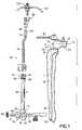
- a portion of the femur of a supine patientis illustrated somewhat schematically at 10 and is seen to include distal femur 12 at the knee K of the patient.
- the femur 10is constrained for rotation about the femoral head (not shown) of the femur 10 and the mechanical axis 14 of the femur 10 passes through the center of rotation of the femoral head and the center 18 of the knee K of the patient.
- the direction of the mechanical axis 14has been determined in the manner described in the aforesaid patent application and an elongate external alignment rod 20 has been affixed to the femur 10, extending in a direction parallel with the mechanical axis 14 of femur 10.
- Alignment rod 20, being parallel with the mechanical axis 14,is available for use in locating cutting guides for making the cuts necessary to prepare the distal femur 12 for the reception of a femoral knee prosthesis to be implanted, as described in the aforesaid patent application.
- the present inventionenables the employment of alignment rod 20 for aligning a tibial resection guide as well, as will be described below.
- Tibia 30 of the recipientincludes proximal tibia 32, tibial eminence 34 and anterior cortex 36, and is to be prepared for the reception of the tibial component of a prosthetic knee implant (not shown) by resection of the proximal tibia 32.
- Tibia 30includes a long axis L and distal tibia 38.
- Apparatus constructed in accordance with the invention for the preparation of the proximal tibia 32is illustrated generally at 40 and is seen to include an external tibial alignment shaft 42 having a proximal, or upper portion in the form of an upper shaft portion 44 and a distal, or lower portion in the form of a tubular member 46.
- Tibial alignment shaft 42extends longitudinally between an upper end 48 and a lower end 50 and upper shaft portion 44 is to be received within tubular member 46 in telescoping engagement adjacent the lower end 50, for selective movement relative to the tubular member 46 along a common alignment axis A.
- Clamping meansshown in the form of a thumbscrew 52 threaded through a collar 54 integral with the tubular member 46 at the upper end 56 of the tubular member 46, selectively clamps the upper shaft portion 44 in place at any location of upper shaft portion 44 along alignment axis A relative to tubular member 46, when the upper shaft portion 44 is telescoped into the tubular member 46.
- Distal coupling means in the form of a lower clamp 60is constructed as described in an earlier patent application in the United States, serial no. 08/552,594, filed November 3, 1995, the disclosure of which application is incorporated herein by reference thereto, and is mounted at the lower end of the tubular member 46, and, consequently, at the lower end 50 of the tibial alignment shaft 42. As seen in FIG.
- lower clamp 60is placed around the distal tibia 38, just above the malleoli, to be secured to the distal tibia 38, for selectively coupling and locating the lower end of the tubular member 46 and, consequently, the lower end 50 of the tibial alignment shaft 42, in alignment with the distal tibia 38, forward of the distal tibia 38, adjacent the ankle 62 of the recipient.
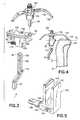
- Alignment meansis shown in the form of an alignment assembly 70 which includes a first carriage 72 integral with the lower end 50 of the tibial alignment shaft 42 and mounted for sliding movement along a first guideway 74 which, in turn, is carried by a second carriage 76 mounted for sliding movement along a second guideway 78 integral with clamp 60.
- the first guideway 74has a rectangular cross-sectional configuration and extends in an anterior-posterior direction for enabling the first carriage 72 to be moved selectively along the first guideway 74 in anterior and posterior directions.
- the second guideway 78has a T-shaped cross-sectional configuration and extends in a medial-lateral direction for enabling the second carriage 76 to be moved selectively along the second guideway 78 in medial and lateral directions.
- First and second carriages 72 and 76are moved to align axis A of the tibial alignment shaft 42 with the center of ankle 62. Once the axis A is aligned as described, a first thumbscrew 80 in the first carriage 72 is tightened to secure the first carriage 72 in place on the first guideway 74, and a second thumbscrew 82 in the second carriage 76 is tightened to secure the second carriage 76 in place on the second guideway 78.
- a tibial resection guide 90is to be assembled with the tibial alignment shaft 42 and located at an appropriate resection location for the accomplishment of the desired proximal cut along the proximal tibia 32.
- tibial resection guide 90includes a cutting guide surface, shown in the form of a saw blade guide slot 92 extending in a medial-lateral direction between the sides of the tibial resection guide 90 and through the tibial resection guide 90 in the anterior-posterior direction.
- a plurality of holes 94also extend through the tibial resection guide 90 in the anterior-posterior direction, all as more fully described in the aforesaid patent application serial no. 08/552,594.
- proximal coupling meansinclude an offset head 100 at the upper end 48 of the tibial alignment shaft 42 for the reception and selective securement of the tibial resection guide 90 to be selectively affixed to the tibial alignment shaft 42 by virtue of the engagement of the offset head 100 with a complementary channel 102 passing through the tibial resection guide 90, and an extension 104 thereof, in the direction parallel to the alignment axis A of the tibial alignment shaft 42 and having an inner surface 106 with a contour configuration generally complementary to the contour configuration of outer surface 108 of the offset head 100 of the tibial alignment shaft 42, at the upper end 48 of the tibial alignment shaft 42.
- the tibial resection guide 90is seated against a stop pin 110, and then a thumbscrew 112, threaded in the tibial resection guide 90, is tightened to secure the tibial
- the resection location of the tibial resection guide 90is determined by a stylus assembly 120 which is most conveniently attached to the tibial resection guide 90 prior to placement of the tibial resection guide 90 on the tibial alignment shaft 42.
- Stylus assembly 120includes a tibial stylus 122 mounted upon a stylus housing 124 and having a tip 126, and is selectively attached to and detached from the tibial resection guide 90 by attachment means shown in the form of a quick-connect mechanism 130, as more fully described in the aforesaid patent application no. 08/552,594.
- upper shaft portion 44 of the tibial alignment shaft 42is inserted into the tubular member 46 and is telescoped downwardly within tubular member 46, with the tibial resection guide 90 coupled to the upper shaft portion 44 of the tibial alignment shaft 42, until tibial stylus 122 of the stylus assembly 120 is seated upon proximal tibia 32, in contact with tibial eminence 34, with the tip 126 of tibial stylus 124 engaging the proximal tibia 32 along the tibial plateau 132, thereby placing the tibial resection guide 90 at the correct level for accomplishing the proximal cut at the desired resection level RL.
- the quick-connect mechanism 130accomplishes a highly stable attachment of the stylus assembly 120 to the tibial resection guide 90 in a compact and easily operated arrangement. Once the tibial resection guide 90 is located at the desired resection level, the thumbscrew 52 is tightened, thereby securing the tibial resection guide 90 at the desired resection level RL, and the stylus assembly 120 is detached from the tibial resection guide 90 by merely operating the quick-disconnect mechanism 130.
- a proximal alignment member 140is placed upon the upper shaft portion 44 of the tibial alignment shaft 42, as illustrated in FIG. 2.
- Proximal alignment member 140itself is best illustrated in FIG. 5 and is seen to include a block 142 and a channel 144 extending through the block 142, the channel 144 having a cross-sectional configuration complementary to the cross-sectional configuration of the upper shaft portion 44 of the tibial alignment shaft 42 for the reception of the upper shaft portion 44 within the channel 144.
- a thumbscrew 146is threaded into the block 142 and communicates with the channel 144 to enable selective securement of the block 144 to the upper shaft portion 44 of the tibial alignment shaft 42, as seen in FIG. 2.
- An alignment guideway in the form of a slot 150extends longitudinally along the block 142 of the proximal alignment member 140 and an opening 152 extends transversely to communicate with the slot 150 along the length of the slot 150 and includes a beveled entrance 154.
- the complementary cross-sectional configurations of the upper shaft portion 44 of the tibial alignment shaft 42 and the channel 144 of the proximal alignment member 140assure that upon engagement of the upper shaft portion 44 within the channel 144, the slot 150 is aligned properly with the axis A of the tibial alignment shaft 42.
- the knee KWith the proximal alignment member 140 secured in place upon the upper shaft portion 44 of the tibial alignment shaft 42, the knee K is placed in extension, as shown in FIGS. 6 and 7.
- the tibial alignment shaft 42is manipulated so that the alignment rod 20 is engaged within the slot 150 of the proximal alignment member 140 to align the proximal alignment member 140 with the alignment rod 20 and, consequently, to align the tibial alignment shaft 42 with the direction of the alignment rod 20, thereby aligning the tibial resection guide 90 relative to the direction of the mechanical axis 14 of the femur 10 and, consequently, relative to the mechanical axis of the leg of the recipient.
- the tibial alignment shaft 42is shifted, as required, during extension of the knee K, to receive the alignment rod 20 transversely through the beveled entrance 154 into the opening 152 and into the slot 150 of the proximal alignment member 140.
- the tibial resection guide 90is aligned relative to the direction of the mechanical axis 14, the tibial resection guide 90 is affixed to the proximal tibia 32, adjacent the anterior cortex 36, by affixation means, shown in the form of drill-pins 160 inserted through selected holes 94 in the tibial resection guide 90 and into the proximal tibia 32. Then, the alignment rod 20 is removed from the femur 10, the tibial alignment shaft 42 is uncoupled from the tibial resection guide 90, the knee K is flexed to ninety degrees, to bring the tibia 30 to the position illustrated in FIG.
- tibial resection guide 90is fully exposed for uninhibited access to the tibial resection guide 90 for resection of the proximal tibia 32.
- a saw blade 162 of a saw 164then is inserted through the saw blade guide slot 92 to accomplish proximal cut 166 at the resection level RL.
- the present inventionattains the several objects and advantages summarized above, namely: Enables the accurate location of the direction of the mechanical axis of the femur interoperatively, without invading the medullary canal and without the necessity for surgical intervention beyond that already required for access to the knee being replaced, to serve in the accurate location of the tibial component, as well as the femoral component of a knee prosthesis, during total knee replacement surgery; provides a relatively simple procedure capable of being performed quickly just prior to preparing the tibia for resection; attains a high degree of accuracy with minimal procedural steps and apparatus; enables a direct determination of the direction of the mechanical axis of the femur and the relative location of a tibial resection guide with less reliance upon visual estimation or interpretation; provides simplified apparatus capable of long-term reliable performance.
Landscapes
- Health & Medical Sciences (AREA)
- Surgery (AREA)
- Life Sciences & Earth Sciences (AREA)
- Biomedical Technology (AREA)
- Medical Informatics (AREA)
- Oral & Maxillofacial Surgery (AREA)
- Nuclear Medicine, Radiotherapy & Molecular Imaging (AREA)
- Transplantation (AREA)
- Physical Education & Sports Medicine (AREA)
- Engineering & Computer Science (AREA)
- Orthopedic Medicine & Surgery (AREA)
- Heart & Thoracic Surgery (AREA)
- Dentistry (AREA)
- Molecular Biology (AREA)
- Animal Behavior & Ethology (AREA)
- General Health & Medical Sciences (AREA)
- Public Health (AREA)
- Veterinary Medicine (AREA)
- Surgical Instruments (AREA)
- Prostheses (AREA)
Abstract
Description
Claims (10)
- Apparatus for aligning a tibial resection guide relativeto the direction of the mechanical axis of the leg of a recipientof a total knee prosthesis wherein the tibial resection guide is tobe affixed to the tibia of the recipient, at the proximal tibia ofthe tibia, for resection of the proximal tibia, the tibia includinga distal tibia, and wherein an external alignment rod is affixed tothe femur and extends in the direction of the mechanical axis, theapparatus comprising:an external tibial alignment shaft extending longitudinallyalong an alignment axis between an upper end and a lower end, thetibial alignment shaft having a proximal portion adjacent the upperend for placement adjacent the proximal tibia and a distal portionadjacent the lower end for placement adjacent the distal tibia;proximal coupling means adjacent the upper end of the tibialalignment shaft for selectively coupling the tibial resection guideto the proximal portion of the tibial alignment shaft;distal coupling means for selectively coupling the distalportion of tibial alignment shaft to the distal tibia, forward ofthe tibia; anda proximal alignment member at the proximal portion of thetibial alignment shaft, the proximal alignment member including analignment guideway extending longitudinally along the proximalalignment member, parallel to the alignment axis of the tibial alignment shaft, the alignment guideway having an opening forreception of the external alignment rod into the alignmentguideway, the alignment guideway being complementary to theexternal alignment rod such that upon reception of the externalalignment rod into the alignment guideway, the proximal alignmentmember will be aligned with the external alignment rod to bring theproximal portion of the tibial alignment shaft into alignment withthe direction of the external alignment rod for aligning the tibialresection guide relative to the direction of the mechanical axis ofthe leg.
- In an apparatus for aligning a tibial resection guiderelative to the direction of the mechanical axis of the leg of arecipient of a total knee prosthesis wherein the tibial resectionguide is to be affixed to the tibia of the recipient, at theproximal tibia of the tibia, for resection of the proximal tibia,the tibia including a distal tibia, and wherein an externalalignment rod is affixed to the femur and extends in the directionof the mechanical axis, an external tibial alignment shaft extendslongitudinally along an alignment axis between an upper end and alower end, the tibial alignment shaft having a proximal portionadjacent the upper end for placement adjacent the proximal tibiaand a distal portion adjacent the lower end for placement adjacentthe distal tibia, proximal coupling means are placed adjacentthe upper end of the tibial alignment shaft for selectivelycoupling the tibial resection guide to the proximal portion of the tibial alignment shaft, and distal coupling means are located forselectively coupling the distal portion of tibial alignment shaftto the distal tibia, forward of the tibia, the improvement comprising:
a proximal alignment member for placement on the proximalportion of the tibial alignment shaft, the proximal alignmentmember including an alignment guideway extending longitudinallyalong the proximal alignment member, parallel to the alignment axisof the tibial alignment shaft, the alignment guideway having anopening for reception of the external alignment rod into thealignment guideway, the alignment guideway being complementary tothe external alignment rod such that upon reception of the externalalignment rod into the alignment guideway, the proximal alignmentmember will be aligned with the external alignment rod to bring theproximal portion of the tibial alignment shaft into alignment withthe direction of the external alignment rod for aligning the tibialresection guide relative to the direction of the mechanical axis ofthe leg. - The invention as claimed in claim 1 or 2 wherein the alignment guidewayincludes a slot extending longitudinally along the proximalalignment member, and the opening extends in a transverse directionsuch that the proximal portion of the tibial alignment shaft isreceived in a transverse direction into the slot.
- The invention as claimed in one of claims 1-3 wherein the proximal alignmentmember includes selective coupling means for selectively coupling and uncoupling the proximal alignment member and the proximalportion of the tibial alignment shaft.
- The invention of claim 4 wherein the selective couplingmeans includes complementary cross-sectional configurations in theproximal alignment member and on the proximal portion of the tibialalignment shaft, the complementary cross-sectional configurationsaligning the slot with the alignment axis of the tibial alignmentshaft upon placement of the proximal alignment member on theproximal portion of the tibial alignment shaft.
- Method for aligning a tibial resection guide relative tothe direction of the mechanical axis of the leg of a recipient ofa total knee prosthesis wherein the tibial resection guide is to beaffixed to the tibia of the recipient, at the proximal tibia of thetibia, for resection of the proximal tibia, the tibia including adistal tibia, the method comprising:affixing an external alignment rod to the femur such that theexternal alignment rod extends in the direction of the mechanicalaxis;coupling a distal portion of an external tibial alignmentshaft to the distal tibia, forward of the tibia, the externaltibial alignment shaft extending longitudinally along an alignmentaxis and having a proximal portion adjacent the proximal tibiawhen the distal portion is coupled to the distal tibia;coupling the tibial resection guide with the proximal portionof the tibial alignment shaft; andpositioning the proximal portion of the tibial alignment shaftsuch that a proximal alignment member on the proximal portion ofthe tibial alignment shaft is engaged with the external alignmentrod to align the proximal alignment member with the externalalignment rod and bring the proximal portion of the tibialalignment shaft into alignment with the direction of the externalalignment rod for aligning the tibial resection guide relative tothe direction of the mechanical axis of the leg.
- The invention as claimed in claim 6 wherein the proximal alignmentmember includes an alignment guideway extending longitudinallyparallel to the alignment axis of the external tibial shaft, andthe proximal alignment member is engaged with the externalalignment rod by relative transverse movement between the proximalalignment member and the external alignment rod.
- The invention as claimed in claim 6 or 7 including coupling the proximalalignment member with the proximal portion of the external tibial shaft prior to engagement of the proximal alignment member with theexternal alignment rod.
- The invention of claim 7 or 8 including affixing the tibialresection guide to the proximal tibia subsequent to alignment ofthe tibial resection guide with the mechanical axis of the leg.
- The invention of claim 9 including resecting theproximal tibia subsequent to affixing the tibial resection guide tothe proximal tibia.
Applications Claiming Priority (2)
| Application Number | Priority Date | Filing Date | Title |
|---|---|---|---|
| US741434 | 1996-10-30 | ||
| US08/741,434US5788700A (en) | 1996-10-30 | 1996-10-30 | Apparatus and method for the alignment of a total knee prosthesis |
Publications (3)
| Publication Number | Publication Date |
|---|---|
| EP0839501A2true EP0839501A2 (en) | 1998-05-06 |
| EP0839501A3 EP0839501A3 (en) | 1998-07-08 |
| EP0839501B1 EP0839501B1 (en) | 2003-03-12 |
Family
ID=24980707
Family Applications (1)
| Application Number | Title | Priority Date | Filing Date |
|---|---|---|---|
| EP97308628AExpired - LifetimeEP0839501B1 (en) | 1996-10-30 | 1997-10-29 | Apparatus and method for the alignment of a total knee prosthesis |
Country Status (6)
| Country | Link |
|---|---|
| US (1) | US5788700A (en) |
| EP (1) | EP0839501B1 (en) |
| JP (1) | JP3748686B2 (en) |
| AU (1) | AU715650B2 (en) |
| CA (1) | CA2219567C (en) |
| DE (1) | DE69719663T2 (en) |
Cited By (6)
| Publication number | Priority date | Publication date | Assignee | Title |
|---|---|---|---|---|
| WO2000071035A1 (en)* | 1999-05-20 | 2000-11-30 | Depuy International Limited | Bone resection guide |
| DE20014377U1 (en)* | 2000-08-19 | 2002-01-10 | Stratec Medical Ag, Oberdorf | Device for optimizing a knee endoprosthesis |
| FR2840797A1 (en)* | 2002-06-17 | 2003-12-19 | Domenico Brocchetta | Device for placing a unicompartment orthopaedic knee prosthesis in position has tibial plate corresponding to tibial resection and having fixtures for mounting femoral cup guide to link femoral and tibial cups |
| WO2021209496A3 (en)* | 2020-04-15 | 2021-12-09 | Aesculap Ag | Alignment device for a tibial resection guide |
| US11751883B2 (en) | 2018-11-28 | 2023-09-12 | Aesculap Ag | Fixing system and aligning device |
| US12042157B2 (en) | 2019-02-15 | 2024-07-23 | Aesculap Ag | Fixing clamp and aligning device |
Families Citing this family (98)
| Publication number | Priority date | Publication date | Assignee | Title |
|---|---|---|---|---|
| US5961555A (en) | 1998-03-17 | 1999-10-05 | Huebner; Randall J. | Modular shoulder prosthesis |
| US6494913B1 (en) | 1998-03-17 | 2002-12-17 | Acumed, Inc. | Shoulder prosthesis |
| ATE334629T1 (en) | 1998-05-19 | 2006-08-15 | Synthes Ag | CONNECTING ELEMENT FOR MONOLATERAL EXTERNAL FIXATION SYSTEM FOR TRAUMATOLOGY AND ORTHOPEDIC |
| EP1079751B1 (en) | 1998-05-19 | 2007-02-28 | Synthes GmbH | Cheek for a one-sided external fixation system for traumatology and orthopedics |
| US6616696B1 (en) | 1998-09-04 | 2003-09-09 | Alan C. Merchant | Modular knee replacement system |
| US7104996B2 (en) | 2000-01-14 | 2006-09-12 | Marctec. Llc | Method of performing surgery |
| US7635390B1 (en) | 2000-01-14 | 2009-12-22 | Marctec, Llc | Joint replacement component having a modular articulating surface |
| US6702821B2 (en) | 2000-01-14 | 2004-03-09 | The Bonutti 2003 Trust A | Instrumentation for minimally invasive joint replacement and methods for using same |
| DK174402B1 (en)* | 2000-05-09 | 2003-02-10 | Gn Netcom As | communication Unit |
| EP1190676B1 (en)* | 2000-09-26 | 2003-08-13 | BrainLAB AG | Device for determining the position of a cutting guide |
| US7909831B2 (en)* | 2001-02-28 | 2011-03-22 | Howmedica Osteonics Corp. | Systems used in performing femoral and tibial resection in knee surgery |
| US6595997B2 (en)* | 2001-02-28 | 2003-07-22 | Howmedica Osteonics Corp. | Methods used in performing femoral and tibial resection in knee surgery |
| US6685711B2 (en)* | 2001-02-28 | 2004-02-03 | Howmedica Osteonics Corp. | Apparatus used in performing femoral and tibial resection in knee surgery |
| US20020133162A1 (en)* | 2001-03-17 | 2002-09-19 | Axelson Stuart L. | Tools used in performing femoral and tibial resection in knee surgery |
| US7708741B1 (en) | 2001-08-28 | 2010-05-04 | Marctec, Llc | Method of preparing bones for knee replacement surgery |
| US7618421B2 (en)* | 2001-10-10 | 2009-11-17 | Howmedica Osteonics Corp. | Tools for femoral resection in knee surgery |
| AUPR865701A0 (en)* | 2001-11-02 | 2001-11-29 | Egan, Michael | Surgical apparatus and surgical methods |
| JP2003144454A (en)* | 2001-11-16 | 2003-05-20 | Yoshio Koga | Joint operation support information computing method, joint operation support information computing program, and joint operation support information computing system |
| WO2003063682A2 (en)* | 2002-01-25 | 2003-08-07 | Depuy Products, Inc. | Extramedullary fluoroscopic alignment guide |
| EP1555963A4 (en) | 2002-10-23 | 2008-12-31 | Mako Surgical Corp | Modular femoral component for a total knee joint replacement for minimally invasive implantation |
| US7094241B2 (en)* | 2002-11-27 | 2006-08-22 | Zimmer Technology, Inc. | Method and apparatus for achieving correct limb alignment in unicondylar knee arthroplasty |
| US7029477B2 (en)* | 2002-12-20 | 2006-04-18 | Zimmer Technology, Inc. | Surgical instrument and positioning method |
| US7887542B2 (en) | 2003-01-15 | 2011-02-15 | Biomet Manufacturing Corp. | Method and apparatus for less invasive knee resection |
| US7789885B2 (en) | 2003-01-15 | 2010-09-07 | Biomet Manufacturing Corp. | Instrumentation for knee resection |
| US8551100B2 (en) | 2003-01-15 | 2013-10-08 | Biomet Manufacturing, Llc | Instrumentation for knee resection |
| US7837690B2 (en) | 2003-01-15 | 2010-11-23 | Biomet Manufacturing Corp. | Method and apparatus for less invasive knee resection |
| US20040153066A1 (en)* | 2003-02-03 | 2004-08-05 | Coon Thomas M. | Apparatus for knee surgery and method of use |
| US7309339B2 (en) | 2003-02-04 | 2007-12-18 | Howmedica Osteonics Corp. | Apparatus for aligning an instrument during a surgical procedure |
| DE50303568D1 (en)* | 2003-04-25 | 2006-07-06 | Zimmer Gmbh | Device for preparing a femoral condyle |
| US7559931B2 (en) | 2003-06-09 | 2009-07-14 | OrthAlign, Inc. | Surgical orientation system and method |
| ATE289787T1 (en) | 2003-09-15 | 2005-03-15 | Zimmer Gmbh | ADJUSTMENT DEVICE |
| US7488324B1 (en) | 2003-12-08 | 2009-02-10 | Biomet Manufacturing Corporation | Femoral guide for implanting a femoral knee prosthesis |
| US7335206B2 (en)* | 2003-12-26 | 2008-02-26 | Zimmer Technology, Inc. | Adjustable resection guide |
| US7641661B2 (en)* | 2003-12-26 | 2010-01-05 | Zimmer Technology, Inc. | Adjustable resection guide |
| US7364581B2 (en)* | 2004-01-14 | 2008-04-29 | Howmedica Osteonics Corp. | Variable angle cutting block |
| US7993341B2 (en) | 2004-03-08 | 2011-08-09 | Zimmer Technology, Inc. | Navigated orthopaedic guide and method |
| US8114086B2 (en) | 2004-03-08 | 2012-02-14 | Zimmer Technology, Inc. | Navigated cut guide locator |
| US8167888B2 (en)* | 2004-08-06 | 2012-05-01 | Zimmer Technology, Inc. | Tibial spacer blocks and femoral cutting guide |
| US20060200158A1 (en)* | 2005-01-29 | 2006-09-07 | Farling Toby N | Apparatuses and methods for arthroplastic surgery |
| US7695479B1 (en) | 2005-04-12 | 2010-04-13 | Biomet Manufacturing Corp. | Femoral sizer |
| US7601154B2 (en)* | 2005-04-18 | 2009-10-13 | Uni-Knee, Llc | Unicondylar knee instrument system |
| US7520880B2 (en) | 2006-01-09 | 2009-04-21 | Zimmer Technology, Inc. | Adjustable surgical support base with integral hinge |
| US7744600B2 (en) | 2006-01-10 | 2010-06-29 | Zimmer Technology, Inc. | Bone resection guide and method |
| US7780671B2 (en)* | 2006-01-23 | 2010-08-24 | Zimmer Technology, Inc. | Bone resection apparatus and method for knee surgery |
| US20070186738A1 (en)* | 2006-01-31 | 2007-08-16 | Zimmer Technology, Inc. | Tibial cut guide assembly having rotatable cut guide body |
| US9113971B2 (en) | 2006-02-27 | 2015-08-25 | Biomet Manufacturing, Llc | Femoral acetabular impingement guide |
| US8070752B2 (en) | 2006-02-27 | 2011-12-06 | Biomet Manufacturing Corp. | Patient specific alignment guide and inter-operative adjustment |
| US9289253B2 (en) | 2006-02-27 | 2016-03-22 | Biomet Manufacturing, Llc | Patient-specific shoulder guide |
| US9907659B2 (en) | 2007-04-17 | 2018-03-06 | Biomet Manufacturing, Llc | Method and apparatus for manufacturing an implant |
| US8603180B2 (en) | 2006-02-27 | 2013-12-10 | Biomet Manufacturing, Llc | Patient-specific acetabular alignment guides |
| US9918740B2 (en) | 2006-02-27 | 2018-03-20 | Biomet Manufacturing, Llc | Backup surgical instrument system and method |
| US9173661B2 (en) | 2006-02-27 | 2015-11-03 | Biomet Manufacturing, Llc | Patient specific alignment guide with cutting surface and laser indicator |
| US10278711B2 (en) | 2006-02-27 | 2019-05-07 | Biomet Manufacturing, Llc | Patient-specific femoral guide |
| US7780672B2 (en) | 2006-02-27 | 2010-08-24 | Biomet Manufacturing Corp. | Femoral adjustment device and associated method |
| US20150335438A1 (en) | 2006-02-27 | 2015-11-26 | Biomet Manufacturing, Llc. | Patient-specific augments |
| US9345548B2 (en) | 2006-02-27 | 2016-05-24 | Biomet Manufacturing, Llc | Patient-specific pre-operative planning |
| US8407067B2 (en) | 2007-04-17 | 2013-03-26 | Biomet Manufacturing Corp. | Method and apparatus for manufacturing an implant |
| US8591516B2 (en) | 2006-02-27 | 2013-11-26 | Biomet Manufacturing, Llc | Patient-specific orthopedic instruments |
| US9339278B2 (en) | 2006-02-27 | 2016-05-17 | Biomet Manufacturing, Llc | Patient-specific acetabular guides and associated instruments |
| US7695520B2 (en) | 2006-05-31 | 2010-04-13 | Biomet Manufacturing Corp. | Prosthesis and implementation system |
| US9795399B2 (en) | 2006-06-09 | 2017-10-24 | Biomet Manufacturing, Llc | Patient-specific knee alignment guide and associated method |
| US20080109085A1 (en)* | 2006-11-03 | 2008-05-08 | Howmedica Osteonics Corp. | Method and apparatus for hip femoral resurfacing tooling |
| US7537618B2 (en)* | 2006-11-13 | 2009-05-26 | Howmedica Osteonics Corp. | Modular humeral head |
| US20090234360A1 (en)* | 2006-12-12 | 2009-09-17 | Vladimir Alexander | Laser assisted total joint arthroplasty |
| GB2447702A (en) | 2007-03-23 | 2008-09-24 | Univ Leeds | Surgical bone cutting template |
| GB0718418D0 (en)* | 2007-09-21 | 2007-10-31 | Depuy Int Ltd | Adjustable surgical instrument |
| US8265949B2 (en) | 2007-09-27 | 2012-09-11 | Depuy Products, Inc. | Customized patient surgical plan |
| EP2194889B1 (en) | 2007-09-30 | 2015-09-23 | DePuy Products, Inc. | Customized patient-specific orthopaedic surgical instrumentation |
| US8357111B2 (en) | 2007-09-30 | 2013-01-22 | Depuy Products, Inc. | Method and system for designing patient-specific orthopaedic surgical instruments |
| AU2009273863B2 (en) | 2008-07-24 | 2014-12-18 | OrthAlign, Inc. | Systems and methods for joint replacement |
| AU2009291743B2 (en) | 2008-09-10 | 2015-02-05 | Orthalign, Inc | Hip surgery systems and methods |
| US10869771B2 (en) | 2009-07-24 | 2020-12-22 | OrthAlign, Inc. | Systems and methods for joint replacement |
| US8118815B2 (en) | 2009-07-24 | 2012-02-21 | OrthAlign, Inc. | Systems and methods for joint replacement |
| US9968376B2 (en) | 2010-11-29 | 2018-05-15 | Biomet Manufacturing, Llc | Patient-specific orthopedic instruments |
| US9241745B2 (en) | 2011-03-07 | 2016-01-26 | Biomet Manufacturing, Llc | Patient-specific femoral version guide |
| US8968412B2 (en) | 2011-06-30 | 2015-03-03 | Depuy (Ireland) | Trialing system for a knee prosthesis and method of use |
| US8926619B2 (en) | 2011-06-30 | 2015-01-06 | Depuy (Ireland) | Method of surgically preparing a tibia for implantation of a prosthetic component |
| US8951301B2 (en) | 2011-06-30 | 2015-02-10 | Depuy (Ireland) | Method of using a trialing system for a knee prosthesis |
| US20130006378A1 (en) | 2011-06-30 | 2013-01-03 | Wogoman Thomas E | Polymer femoral trial component |
| US8939986B2 (en) | 2011-06-30 | 2015-01-27 | Depuy (Ireland) | Surgical instruments for use in surgically preparing a tibia for implantation of a prosthetic component |
| US8986390B2 (en) | 2011-06-30 | 2015-03-24 | Depuy (Ireland) | Method of trialing a knee prosthesis |
| US8852197B2 (en) | 2011-06-30 | 2014-10-07 | Depuy (Ireland) | Surgical instrument assemblies for use in surgically preparing a tibia for implantation of a prosthetic component |
| US9138237B2 (en) | 2011-10-13 | 2015-09-22 | Arthrex, Inc. | Total joint instrumentation and method for use |
| US9549742B2 (en) | 2012-05-18 | 2017-01-24 | OrthAlign, Inc. | Devices and methods for knee arthroplasty |
| US9649160B2 (en) | 2012-08-14 | 2017-05-16 | OrthAlign, Inc. | Hip replacement navigation system and method |
| DE202012103384U1 (en) | 2012-09-05 | 2012-09-24 | Signus Medizintechnik Gmbh | Pelvic ring implant |
| US9427240B2 (en)* | 2013-03-21 | 2016-08-30 | Von Zabern Surgical | System and method for performing measurable and controled osteotomy |
| US9861491B2 (en) | 2014-04-30 | 2018-01-09 | Depuy Ireland Unlimited Company | Tibial trial system for a knee prosthesis |
| US10363149B2 (en) | 2015-02-20 | 2019-07-30 | OrthAlign, Inc. | Hip replacement navigation system and method |
| US10195056B2 (en) | 2015-10-19 | 2019-02-05 | Depuy Ireland Unlimited Company | Method for preparing a patient's tibia to receive an implant |
| US10537445B2 (en) | 2015-10-19 | 2020-01-21 | Depuy Ireland Unlimited Company | Surgical instruments for preparing a patient's tibia to receive an implant |
| US10722310B2 (en) | 2017-03-13 | 2020-07-28 | Zimmer Biomet CMF and Thoracic, LLC | Virtual surgery planning system and method |
| CA3056495A1 (en) | 2017-03-14 | 2018-09-20 | OrthAlign, Inc. | Soft tissue measurement & balancing systems and methods |
| EP3595554A4 (en) | 2017-03-14 | 2021-01-06 | OrthAlign, Inc. | Hip replacement navigation systems and methods |
| US11051829B2 (en) | 2018-06-26 | 2021-07-06 | DePuy Synthes Products, Inc. | Customized patient-specific orthopaedic surgical instrument |
| JP7294824B2 (en) | 2019-02-14 | 2023-06-20 | 京セラ株式会社 | surgical instruments |
| CN112370222B (en)* | 2020-10-29 | 2022-06-17 | 北京市春立正达医疗器械股份有限公司 | Self-fixing tibial plateau test mold |
| US20230372121A1 (en)* | 2022-05-20 | 2023-11-23 | Steensen Orthopedic Systems, LLC | Tibial dual stylus instrument having wide convex stylus tips and components thereof |
Citations (2)
| Publication number | Priority date | Publication date | Assignee | Title |
|---|---|---|---|---|
| US5601566A (en) | 1994-02-22 | 1997-02-11 | Osteonics Corp. | Method and apparatus for the alignment of a femoral knee prosthesis |
| US5704941A (en) | 1995-11-03 | 1998-01-06 | Osteonics Corp. | Tibial preparation apparatus and method |
Family Cites Families (10)
| Publication number | Priority date | Publication date | Assignee | Title |
|---|---|---|---|---|
| US3596554A (en)* | 1970-05-19 | 1971-08-03 | Nasa | Safety-type locking pin |
| US4738253A (en)* | 1981-12-31 | 1988-04-19 | Biomedical Engineering Trust | Guides for inclined surgical cuts or resections |
| US4524766A (en)* | 1982-01-07 | 1985-06-25 | Petersen Thomas D | Surgical knee alignment method and system |
| US4653488A (en)* | 1982-02-18 | 1987-03-31 | Howmedica, Inc. | Prosthetic knee implantation |
| US4759350A (en)* | 1986-10-17 | 1988-07-26 | Dunn Harold K | Instruments for shaping distal femoral and proximal tibial surfaces |
| US4841975A (en)* | 1987-04-15 | 1989-06-27 | Cemax, Inc. | Preoperative planning of bone cuts and joint replacement using radiant energy scan imaging |
| US4938762A (en)* | 1987-12-16 | 1990-07-03 | Protek Ag | Reference system for implantation of condylar total knee prostheses |
| US5171244A (en)* | 1990-01-08 | 1992-12-15 | Caspari Richard B | Methods and apparatus for arthroscopic prosthetic knee replacement |
| US5100408A (en)* | 1991-03-07 | 1992-03-31 | Smith & Nephew Richards Inc. | Femoral instrumentation for long stem surgery |
| CA2098081A1 (en)* | 1992-08-13 | 1994-02-14 | Terry L. Dietz | Alignment guide and method |
- 1996
- 1996-10-30USUS08/741,434patent/US5788700A/ennot_activeExpired - Lifetime
- 1997
- 1997-10-16AUAU41884/97Apatent/AU715650B2/ennot_activeCeased
- 1997-10-28CACA002219567Apatent/CA2219567C/ennot_activeExpired - Fee Related
- 1997-10-29DEDE69719663Tpatent/DE69719663T2/ennot_activeExpired - Lifetime
- 1997-10-29EPEP97308628Apatent/EP0839501B1/ennot_activeExpired - Lifetime
- 1997-10-29JPJP31271197Apatent/JP3748686B2/ennot_activeExpired - Fee Related
Patent Citations (2)
| Publication number | Priority date | Publication date | Assignee | Title |
|---|---|---|---|---|
| US5601566A (en) | 1994-02-22 | 1997-02-11 | Osteonics Corp. | Method and apparatus for the alignment of a femoral knee prosthesis |
| US5704941A (en) | 1995-11-03 | 1998-01-06 | Osteonics Corp. | Tibial preparation apparatus and method |
Cited By (6)
| Publication number | Priority date | Publication date | Assignee | Title |
|---|---|---|---|---|
| WO2000071035A1 (en)* | 1999-05-20 | 2000-11-30 | Depuy International Limited | Bone resection guide |
| DE20014377U1 (en)* | 2000-08-19 | 2002-01-10 | Stratec Medical Ag, Oberdorf | Device for optimizing a knee endoprosthesis |
| FR2840797A1 (en)* | 2002-06-17 | 2003-12-19 | Domenico Brocchetta | Device for placing a unicompartment orthopaedic knee prosthesis in position has tibial plate corresponding to tibial resection and having fixtures for mounting femoral cup guide to link femoral and tibial cups |
| US11751883B2 (en) | 2018-11-28 | 2023-09-12 | Aesculap Ag | Fixing system and aligning device |
| US12042157B2 (en) | 2019-02-15 | 2024-07-23 | Aesculap Ag | Fixing clamp and aligning device |
| WO2021209496A3 (en)* | 2020-04-15 | 2021-12-09 | Aesculap Ag | Alignment device for a tibial resection guide |
Also Published As
| Publication number | Publication date |
|---|---|
| JPH10174695A (en) | 1998-06-30 |
| DE69719663D1 (en) | 2003-04-17 |
| CA2219567A1 (en) | 1998-04-30 |
| EP0839501B1 (en) | 2003-03-12 |
| CA2219567C (en) | 2006-08-01 |
| JP3748686B2 (en) | 2006-02-22 |
| AU715650B2 (en) | 2000-02-10 |
| EP0839501A3 (en) | 1998-07-08 |
| US5788700A (en) | 1998-08-04 |
| AU4188497A (en) | 1998-05-07 |
| DE69719663T2 (en) | 2003-11-06 |
Similar Documents
| Publication | Publication Date | Title |
|---|---|---|
| US5788700A (en) | Apparatus and method for the alignment of a total knee prosthesis | |
| US7083624B2 (en) | Extramedullary fluoroscopic alignment guide | |
| CA2142083C (en) | Method and apparatus for the alignment of a femoral knee prosthesis | |
| US6685711B2 (en) | Apparatus used in performing femoral and tibial resection in knee surgery | |
| US5417694A (en) | Distal femoral cutting guide apparatus with anterior or posterior referencing for use in knee joint replacement surgery | |
| US6595997B2 (en) | Methods used in performing femoral and tibial resection in knee surgery | |
| US7909831B2 (en) | Systems used in performing femoral and tibial resection in knee surgery | |
| US5720752A (en) | Distal femoral cutting guide apparatus with anterior or posterior referencing for use in knee joint replacement surgery | |
| EP2001373B1 (en) | Orthopaedic cutting guide instrument | |
| US7998142B2 (en) | Navigated lateral/medial femoral resection guide | |
| US4487203A (en) | Triplanar knee resection method | |
| US6193723B1 (en) | Intramedullary alignment guide tool | |
| US20060195111A1 (en) | Universal positioning block assembly | |
| US4567885A (en) | Triplanar knee resection system | |
| US5688281A (en) | Intramedullary alignment guide | |
| AU648710B2 (en) | Fermoral cutting guide | |
| US20080097451A1 (en) | Surgical tool assembly for total knee arthroplasty | |
| WO1997030640A9 (en) | Distal femoral cutting guide apparatus | |
| US20020133162A1 (en) | Tools used in performing femoral and tibial resection in knee surgery | |
| CA2537711A1 (en) | Universal positioning block assembly | |
| JP2000287983A (en) | Thigh bone extramedullary clamp guide device for artificial patella replacing technique | |
| WO1999038464A1 (en) | An orthopaedic apparatus | |
| AU2006202002A1 (en) | Universal positioning block assembly |
Legal Events
| Date | Code | Title | Description |
|---|---|---|---|
| PUAI | Public reference made under article 153(3) epc to a published international application that has entered the european phase | Free format text:ORIGINAL CODE: 0009012 | |
| AK | Designated contracting states | Kind code of ref document:A2 Designated state(s):BE DE FR GB IT LU NL | |
| AX | Request for extension of the european patent | Free format text:AL;LT;LV;RO;SI | |
| PUAL | Search report despatched | Free format text:ORIGINAL CODE: 0009013 | |
| AK | Designated contracting states | Kind code of ref document:A3 Designated state(s):AT BE CH DE DK ES FI FR GB GR IE IT LI LU MC NL PT SE | |
| AX | Request for extension of the european patent | Free format text:AL;LT;LV;RO;SI | |
| 17P | Request for examination filed | Effective date:19990104 | |
| AKX | Designation fees paid | Free format text:BE DE FR GB IT LU NL | |
| RBV | Designated contracting states (corrected) | Designated state(s):BE DE FR GB IT LU NL | |
| 17Q | First examination report despatched | Effective date:20011227 | |
| GRAG | Despatch of communication of intention to grant | Free format text:ORIGINAL CODE: EPIDOS AGRA | |
| GRAG | Despatch of communication of intention to grant | Free format text:ORIGINAL CODE: EPIDOS AGRA | |
| GRAH | Despatch of communication of intention to grant a patent | Free format text:ORIGINAL CODE: EPIDOS IGRA | |
| GRAH | Despatch of communication of intention to grant a patent | Free format text:ORIGINAL CODE: EPIDOS IGRA | |
| GRAA | (expected) grant | Free format text:ORIGINAL CODE: 0009210 | |
| AK | Designated contracting states | Designated state(s):BE DE FR GB IT LU NL | |
| PG25 | Lapsed in a contracting state [announced via postgrant information from national office to epo] | Ref country code:NL Free format text:LAPSE BECAUSE OF FAILURE TO SUBMIT A TRANSLATION OF THE DESCRIPTION OR TO PAY THE FEE WITHIN THE PRESCRIBED TIME-LIMIT Effective date:20030312 Ref country code:BE Free format text:LAPSE BECAUSE OF FAILURE TO SUBMIT A TRANSLATION OF THE DESCRIPTION OR TO PAY THE FEE WITHIN THE PRESCRIBED TIME-LIMIT Effective date:20030312 | |
| REG | Reference to a national code | Ref country code:GB Ref legal event code:FG4D | |
| REF | Corresponds to: | Ref document number:69719663 Country of ref document:DE Date of ref document:20030417 Kind code of ref document:P | |
| NLV1 | Nl: lapsed or annulled due to failure to fulfill the requirements of art. 29p and 29m of the patents act | ||
| PG25 | Lapsed in a contracting state [announced via postgrant information from national office to epo] | Ref country code:LU Free format text:LAPSE BECAUSE OF NON-PAYMENT OF DUE FEES Effective date:20031029 | |
| ET | Fr: translation filed | ||
| PLBE | No opposition filed within time limit | Free format text:ORIGINAL CODE: 0009261 | |
| STAA | Information on the status of an ep patent application or granted ep patent | Free format text:STATUS: NO OPPOSITION FILED WITHIN TIME LIMIT | |
| 26N | No opposition filed | Effective date:20031215 | |
| PGFP | Annual fee paid to national office [announced via postgrant information from national office to epo] | Ref country code:FR Payment date:20101112 Year of fee payment:14 | |
| PGFP | Annual fee paid to national office [announced via postgrant information from national office to epo] | Ref country code:DE Payment date:20101206 Year of fee payment:14 | |
| PG25 | Lapsed in a contracting state [announced via postgrant information from national office to epo] | Ref country code:IT Free format text:LAPSE BECAUSE OF NON-PAYMENT OF DUE FEES Effective date:20091029 | |
| PGFP | Annual fee paid to national office [announced via postgrant information from national office to epo] | Ref country code:GB Payment date:20101028 Year of fee payment:14 | |
| PGFP | Annual fee paid to national office [announced via postgrant information from national office to epo] | Ref country code:IT Payment date:20101025 Year of fee payment:14 | |
| PGRI | Patent reinstated in contracting state [announced from national office to epo] | Ref country code:IT Effective date:20110616 | |
| GBPC | Gb: european patent ceased through non-payment of renewal fee | Effective date:20111029 | |
| REG | Reference to a national code | Ref country code:FR Ref legal event code:ST Effective date:20120629 | |
| PG25 | Lapsed in a contracting state [announced via postgrant information from national office to epo] | Ref country code:DE Free format text:LAPSE BECAUSE OF NON-PAYMENT OF DUE FEES Effective date:20120501 | |
| REG | Reference to a national code | Ref country code:DE Ref legal event code:R119 Ref document number:69719663 Country of ref document:DE Effective date:20120501 | |
| PG25 | Lapsed in a contracting state [announced via postgrant information from national office to epo] | Ref country code:IT Free format text:LAPSE BECAUSE OF NON-PAYMENT OF DUE FEES Effective date:20111029 Ref country code:FR Free format text:LAPSE BECAUSE OF NON-PAYMENT OF DUE FEES Effective date:20111102 Ref country code:GB Free format text:LAPSE BECAUSE OF NON-PAYMENT OF DUE FEES Effective date:20111029 |