EP0839499A1 - Surgical suture having an ultrasonically formed tip, and apparatus and method for making same - Google Patents
Surgical suture having an ultrasonically formed tip, and apparatus and method for making sameDownload PDFInfo
- Publication number
- EP0839499A1 EP0839499A1EP97308631AEP97308631AEP0839499A1EP 0839499 A1EP0839499 A1EP 0839499A1EP 97308631 AEP97308631 AEP 97308631AEP 97308631 AEP97308631 AEP 97308631AEP 0839499 A1EP0839499 A1EP 0839499A1
- Authority
- EP
- European Patent Office
- Prior art keywords
- tipping
- surgical suture
- tip
- die
- suture material
- Prior art date
- Legal status (The legal status is an assumption and is not a legal conclusion. Google has not performed a legal analysis and makes no representation as to the accuracy of the status listed.)
- Granted
Links
- 238000000034methodMethods0.000titleclaimsabstractdescription12
- 239000003356suture materialSubstances0.000claimsabstractdescription118
- 238000005520cutting processMethods0.000claimsdescription30
- 239000000463materialSubstances0.000claimsdescription14
- 230000003287optical effectEffects0.000description21
- 238000004519manufacturing processMethods0.000description6
- 238000001514detection methodMethods0.000description5
- 230000008569processEffects0.000description5
- 239000004677NylonSubstances0.000description2
- 230000009471actionEffects0.000description2
- 239000011248coating agentSubstances0.000description2
- 238000000576coating methodMethods0.000description2
- 238000010586diagramMethods0.000description2
- 238000003780insertionMethods0.000description2
- 230000037431insertionEffects0.000description2
- 230000001788irregularEffects0.000description2
- 229920001778nylonPolymers0.000description2
- -1polyethylene terephthalatePolymers0.000description2
- 229920000139polyethylene terephthalatePolymers0.000description2
- 239000005020polyethylene terephthalateSubstances0.000description2
- 239000004952PolyamideSubstances0.000description1
- 229910000831SteelInorganic materials0.000description1
- 229920006362Teflon®Polymers0.000description1
- ATJFFYVFTNAWJD-UHFFFAOYSA-NTinChemical compound[Sn]ATJFFYVFTNAWJD-UHFFFAOYSA-N0.000description1
- 238000010924continuous productionMethods0.000description1
- 238000010438heat treatmentMethods0.000description1
- 230000007246mechanismEffects0.000description1
- 238000012986modificationMethods0.000description1
- 230000004048modificationEffects0.000description1
- 239000013307optical fiberSubstances0.000description1
- 229920002647polyamidePolymers0.000description1
- 229920000728polyesterPolymers0.000description1
- 239000010959steelSubstances0.000description1
- 239000000126substanceSubstances0.000description1
- 229920001169thermoplasticPolymers0.000description1
- 239000004416thermosoftening plasticSubstances0.000description1
- 238000003466weldingMethods0.000description1
Images


Classifications
- B—PERFORMING OPERATIONS; TRANSPORTING
- B29—WORKING OF PLASTICS; WORKING OF SUBSTANCES IN A PLASTIC STATE IN GENERAL
- B29C—SHAPING OR JOINING OF PLASTICS; SHAPING OF MATERIAL IN A PLASTIC STATE, NOT OTHERWISE PROVIDED FOR; AFTER-TREATMENT OF THE SHAPED PRODUCTS, e.g. REPAIRING
- B29C66/00—General aspects of processes or apparatus for joining preformed parts
- B29C66/90—Measuring or controlling the joining process
- B29C66/96—Measuring or controlling the joining process characterised by the method for implementing the controlling of the joining process
- A—HUMAN NECESSITIES
- A61—MEDICAL OR VETERINARY SCIENCE; HYGIENE
- A61B—DIAGNOSIS; SURGERY; IDENTIFICATION
- A61B17/00—Surgical instruments, devices or methods
- A61B17/04—Surgical instruments, devices or methods for suturing wounds; Holders or packages for needles or suture materials
- A61B17/06—Needles ; Sutures; Needle-suture combinations; Holders or packages for needles or suture materials
- A61B17/06195—Apparatus or means for preparing the cut end of the suture thread to be attached to the needle, e.g. tipping to prevent brooming
- B—PERFORMING OPERATIONS; TRANSPORTING
- B29—WORKING OF PLASTICS; WORKING OF SUBSTANCES IN A PLASTIC STATE IN GENERAL
- B29C—SHAPING OR JOINING OF PLASTICS; SHAPING OF MATERIAL IN A PLASTIC STATE, NOT OTHERWISE PROVIDED FOR; AFTER-TREATMENT OF THE SHAPED PRODUCTS, e.g. REPAIRING
- B29C57/00—Shaping of tube ends, e.g. flanging, belling or closing; Apparatus therefor, e.g. collapsible mandrels
- B—PERFORMING OPERATIONS; TRANSPORTING
- B29—WORKING OF PLASTICS; WORKING OF SUBSTANCES IN A PLASTIC STATE IN GENERAL
- B29C—SHAPING OR JOINING OF PLASTICS; SHAPING OF MATERIAL IN A PLASTIC STATE, NOT OTHERWISE PROVIDED FOR; AFTER-TREATMENT OF THE SHAPED PRODUCTS, e.g. REPAIRING
- B29C65/00—Joining or sealing of preformed parts, e.g. welding of plastics materials; Apparatus therefor
- B29C65/02—Joining or sealing of preformed parts, e.g. welding of plastics materials; Apparatus therefor by heating, with or without pressure
- B29C65/08—Joining or sealing of preformed parts, e.g. welding of plastics materials; Apparatus therefor by heating, with or without pressure using ultrasonic vibrations
- B—PERFORMING OPERATIONS; TRANSPORTING
- B29—WORKING OF PLASTICS; WORKING OF SUBSTANCES IN A PLASTIC STATE IN GENERAL
- B29C—SHAPING OR JOINING OF PLASTICS; SHAPING OF MATERIAL IN A PLASTIC STATE, NOT OTHERWISE PROVIDED FOR; AFTER-TREATMENT OF THE SHAPED PRODUCTS, e.g. REPAIRING
- B29C66/00—General aspects of processes or apparatus for joining preformed parts
- B29C66/004—Preventing sticking together, e.g. of some areas of the parts to be joined
- B29C66/0042—Preventing sticking together, e.g. of some areas of the parts to be joined of the joining tool and the parts to be joined
- B—PERFORMING OPERATIONS; TRANSPORTING
- B29—WORKING OF PLASTICS; WORKING OF SUBSTANCES IN A PLASTIC STATE IN GENERAL
- B29C—SHAPING OR JOINING OF PLASTICS; SHAPING OF MATERIAL IN A PLASTIC STATE, NOT OTHERWISE PROVIDED FOR; AFTER-TREATMENT OF THE SHAPED PRODUCTS, e.g. REPAIRING
- B29C66/00—General aspects of processes or apparatus for joining preformed parts
- B29C66/40—General aspects of joining substantially flat articles, e.g. plates, sheets or web-like materials; Making flat seams in tubular or hollow articles; Joining single elements to substantially flat surfaces
- B29C66/41—Joining substantially flat articles ; Making flat seams in tubular or hollow articles
- B29C66/43—Joining a relatively small portion of the surface of said articles
- B—PERFORMING OPERATIONS; TRANSPORTING
- B29—WORKING OF PLASTICS; WORKING OF SUBSTANCES IN A PLASTIC STATE IN GENERAL
- B29C—SHAPING OR JOINING OF PLASTICS; SHAPING OF MATERIAL IN A PLASTIC STATE, NOT OTHERWISE PROVIDED FOR; AFTER-TREATMENT OF THE SHAPED PRODUCTS, e.g. REPAIRING
- B29C66/00—General aspects of processes or apparatus for joining preformed parts
- B29C66/69—General aspects of joining filaments
- B—PERFORMING OPERATIONS; TRANSPORTING
- B29—WORKING OF PLASTICS; WORKING OF SUBSTANCES IN A PLASTIC STATE IN GENERAL
- B29C—SHAPING OR JOINING OF PLASTICS; SHAPING OF MATERIAL IN A PLASTIC STATE, NOT OTHERWISE PROVIDED FOR; AFTER-TREATMENT OF THE SHAPED PRODUCTS, e.g. REPAIRING
- B29C66/00—General aspects of processes or apparatus for joining preformed parts
- B29C66/80—General aspects of machine operations or constructions and parts thereof
- B29C66/81—General aspects of the pressing elements, i.e. the elements applying pressure on the parts to be joined in the area to be joined, e.g. the welding jaws or clamps
- B29C66/812—General aspects of the pressing elements, i.e. the elements applying pressure on the parts to be joined in the area to be joined, e.g. the welding jaws or clamps characterised by the composition, by the structure, by the intensive physical properties or by the optical properties of the material constituting the pressing elements, e.g. constituting the welding jaws or clamps
- B29C66/8122—General aspects of the pressing elements, i.e. the elements applying pressure on the parts to be joined in the area to be joined, e.g. the welding jaws or clamps characterised by the composition, by the structure, by the intensive physical properties or by the optical properties of the material constituting the pressing elements, e.g. constituting the welding jaws or clamps characterised by the composition of the material constituting the pressing elements, e.g. constituting the welding jaws or clamps
- B—PERFORMING OPERATIONS; TRANSPORTING
- B29—WORKING OF PLASTICS; WORKING OF SUBSTANCES IN A PLASTIC STATE IN GENERAL
- B29C—SHAPING OR JOINING OF PLASTICS; SHAPING OF MATERIAL IN A PLASTIC STATE, NOT OTHERWISE PROVIDED FOR; AFTER-TREATMENT OF THE SHAPED PRODUCTS, e.g. REPAIRING
- B29C66/00—General aspects of processes or apparatus for joining preformed parts
- B29C66/80—General aspects of machine operations or constructions and parts thereof
- B29C66/81—General aspects of the pressing elements, i.e. the elements applying pressure on the parts to be joined in the area to be joined, e.g. the welding jaws or clamps
- B29C66/816—General aspects of the pressing elements, i.e. the elements applying pressure on the parts to be joined in the area to be joined, e.g. the welding jaws or clamps characterised by the mounting of the pressing elements, e.g. of the welding jaws or clamps
- B29C66/8161—General aspects of the pressing elements, i.e. the elements applying pressure on the parts to be joined in the area to be joined, e.g. the welding jaws or clamps characterised by the mounting of the pressing elements, e.g. of the welding jaws or clamps said pressing elements being supported or backed-up by springs or by resilient material
- B—PERFORMING OPERATIONS; TRANSPORTING
- B29—WORKING OF PLASTICS; WORKING OF SUBSTANCES IN A PLASTIC STATE IN GENERAL
- B29C—SHAPING OR JOINING OF PLASTICS; SHAPING OF MATERIAL IN A PLASTIC STATE, NOT OTHERWISE PROVIDED FOR; AFTER-TREATMENT OF THE SHAPED PRODUCTS, e.g. REPAIRING
- B29C66/00—General aspects of processes or apparatus for joining preformed parts
- B29C66/80—General aspects of machine operations or constructions and parts thereof
- B29C66/82—Pressure application arrangements, e.g. transmission or actuating mechanisms for joining tools or clamps
- B29C66/824—Actuating mechanisms
- B29C66/8242—Pneumatic or hydraulic drives
- B—PERFORMING OPERATIONS; TRANSPORTING
- B29—WORKING OF PLASTICS; WORKING OF SUBSTANCES IN A PLASTIC STATE IN GENERAL
- B29C—SHAPING OR JOINING OF PLASTICS; SHAPING OF MATERIAL IN A PLASTIC STATE, NOT OTHERWISE PROVIDED FOR; AFTER-TREATMENT OF THE SHAPED PRODUCTS, e.g. REPAIRING
- B29C66/00—General aspects of processes or apparatus for joining preformed parts
- B29C66/80—General aspects of machine operations or constructions and parts thereof
- B29C66/83—General aspects of machine operations or constructions and parts thereof characterised by the movement of the joining or pressing tools
- B29C66/832—Reciprocating joining or pressing tools
- B29C66/8322—Joining or pressing tools reciprocating along one axis
- B—PERFORMING OPERATIONS; TRANSPORTING
- B29—WORKING OF PLASTICS; WORKING OF SUBSTANCES IN A PLASTIC STATE IN GENERAL
- B29C—SHAPING OR JOINING OF PLASTICS; SHAPING OF MATERIAL IN A PLASTIC STATE, NOT OTHERWISE PROVIDED FOR; AFTER-TREATMENT OF THE SHAPED PRODUCTS, e.g. REPAIRING
- B29C66/00—General aspects of processes or apparatus for joining preformed parts
- B29C66/80—General aspects of machine operations or constructions and parts thereof
- B29C66/83—General aspects of machine operations or constructions and parts thereof characterised by the movement of the joining or pressing tools
- B29C66/832—Reciprocating joining or pressing tools
- B29C66/8324—Joining or pressing tools pivoting around one axis
- B29C66/83241—Joining or pressing tools pivoting around one axis cooperating pivoting tools
- B—PERFORMING OPERATIONS; TRANSPORTING
- B29—WORKING OF PLASTICS; WORKING OF SUBSTANCES IN A PLASTIC STATE IN GENERAL
- B29C—SHAPING OR JOINING OF PLASTICS; SHAPING OF MATERIAL IN A PLASTIC STATE, NOT OTHERWISE PROVIDED FOR; AFTER-TREATMENT OF THE SHAPED PRODUCTS, e.g. REPAIRING
- B29C66/00—General aspects of processes or apparatus for joining preformed parts
- B29C66/80—General aspects of machine operations or constructions and parts thereof
- B29C66/83—General aspects of machine operations or constructions and parts thereof characterised by the movement of the joining or pressing tools
- B29C66/834—General aspects of machine operations or constructions and parts thereof characterised by the movement of the joining or pressing tools moving with the parts to be joined
- B29C66/8341—Roller, cylinder or drum types; Band or belt types; Ball types
- B29C66/83411—Roller, cylinder or drum types
- B—PERFORMING OPERATIONS; TRANSPORTING
- B29—WORKING OF PLASTICS; WORKING OF SUBSTANCES IN A PLASTIC STATE IN GENERAL
- B29C—SHAPING OR JOINING OF PLASTICS; SHAPING OF MATERIAL IN A PLASTIC STATE, NOT OTHERWISE PROVIDED FOR; AFTER-TREATMENT OF THE SHAPED PRODUCTS, e.g. REPAIRING
- B29C66/00—General aspects of processes or apparatus for joining preformed parts
- B29C66/80—General aspects of machine operations or constructions and parts thereof
- B29C66/83—General aspects of machine operations or constructions and parts thereof characterised by the movement of the joining or pressing tools
- B29C66/834—General aspects of machine operations or constructions and parts thereof characterised by the movement of the joining or pressing tools moving with the parts to be joined
- B29C66/8351—Jaws mounted on rollers, cylinders, drums, bands, belts or chains; Flying jaws
- B29C66/83511—Jaws mounted on rollers, cylinders, drums, bands, belts or chains; Flying jaws jaws mounted on rollers, cylinders or drums
- B—PERFORMING OPERATIONS; TRANSPORTING
- B29—WORKING OF PLASTICS; WORKING OF SUBSTANCES IN A PLASTIC STATE IN GENERAL
- B29C—SHAPING OR JOINING OF PLASTICS; SHAPING OF MATERIAL IN A PLASTIC STATE, NOT OTHERWISE PROVIDED FOR; AFTER-TREATMENT OF THE SHAPED PRODUCTS, e.g. REPAIRING
- B29C66/00—General aspects of processes or apparatus for joining preformed parts
- B29C66/90—Measuring or controlling the joining process
- B29C66/95—Measuring or controlling the joining process by measuring or controlling specific variables not covered by groups B29C66/91 - B29C66/94
- B29C66/951—Measuring or controlling the joining process by measuring or controlling specific variables not covered by groups B29C66/91 - B29C66/94 by measuring or controlling the vibration frequency and/or the vibration amplitude of vibrating joining tools, e.g. of ultrasonic welding tools
- B29C66/9513—Measuring or controlling the joining process by measuring or controlling specific variables not covered by groups B29C66/91 - B29C66/94 by measuring or controlling the vibration frequency and/or the vibration amplitude of vibrating joining tools, e.g. of ultrasonic welding tools characterised by specific vibration frequency values or ranges
- B—PERFORMING OPERATIONS; TRANSPORTING
- B29—WORKING OF PLASTICS; WORKING OF SUBSTANCES IN A PLASTIC STATE IN GENERAL
- B29C—SHAPING OR JOINING OF PLASTICS; SHAPING OF MATERIAL IN A PLASTIC STATE, NOT OTHERWISE PROVIDED FOR; AFTER-TREATMENT OF THE SHAPED PRODUCTS, e.g. REPAIRING
- B29C2791/00—Shaping characteristics in general
- B29C2791/004—Shaping under special conditions
- B29C2791/008—Using vibrations during moulding
- B—PERFORMING OPERATIONS; TRANSPORTING
- B29—WORKING OF PLASTICS; WORKING OF SUBSTANCES IN A PLASTIC STATE IN GENERAL
- B29C—SHAPING OR JOINING OF PLASTICS; SHAPING OF MATERIAL IN A PLASTIC STATE, NOT OTHERWISE PROVIDED FOR; AFTER-TREATMENT OF THE SHAPED PRODUCTS, e.g. REPAIRING
- B29C66/00—General aspects of processes or apparatus for joining preformed parts
- B29C66/01—General aspects dealing with the joint area or with the area to be joined
- B29C66/05—Particular design of joint configurations
- B29C66/10—Particular design of joint configurations particular design of the joint cross-sections
- B29C66/11—Joint cross-sections comprising a single joint-segment, i.e. one of the parts to be joined comprising a single joint-segment in the joint cross-section
- B29C66/112—Single lapped joints
- B29C66/1122—Single lap to lap joints, i.e. overlap joints
- B—PERFORMING OPERATIONS; TRANSPORTING
- B29—WORKING OF PLASTICS; WORKING OF SUBSTANCES IN A PLASTIC STATE IN GENERAL
- B29C—SHAPING OR JOINING OF PLASTICS; SHAPING OF MATERIAL IN A PLASTIC STATE, NOT OTHERWISE PROVIDED FOR; AFTER-TREATMENT OF THE SHAPED PRODUCTS, e.g. REPAIRING
- B29C66/00—General aspects of processes or apparatus for joining preformed parts
- B29C66/70—General aspects of processes or apparatus for joining preformed parts characterised by the composition, physical properties or the structure of the material of the parts to be joined; Joining with non-plastics material
- B29C66/71—General aspects of processes or apparatus for joining preformed parts characterised by the composition, physical properties or the structure of the material of the parts to be joined; Joining with non-plastics material characterised by the composition of the plastics material of the parts to be joined
- B—PERFORMING OPERATIONS; TRANSPORTING
- B29—WORKING OF PLASTICS; WORKING OF SUBSTANCES IN A PLASTIC STATE IN GENERAL
- B29C—SHAPING OR JOINING OF PLASTICS; SHAPING OF MATERIAL IN A PLASTIC STATE, NOT OTHERWISE PROVIDED FOR; AFTER-TREATMENT OF THE SHAPED PRODUCTS, e.g. REPAIRING
- B29C66/00—General aspects of processes or apparatus for joining preformed parts
- B29C66/70—General aspects of processes or apparatus for joining preformed parts characterised by the composition, physical properties or the structure of the material of the parts to be joined; Joining with non-plastics material
- B29C66/73—General aspects of processes or apparatus for joining preformed parts characterised by the composition, physical properties or the structure of the material of the parts to be joined; Joining with non-plastics material characterised by the intensive physical properties of the material of the parts to be joined, by the optical properties of the material of the parts to be joined, by the extensive physical properties of the parts to be joined, by the state of the material of the parts to be joined or by the material of the parts to be joined being a thermoplastic or a thermoset
- B29C66/739—General aspects of processes or apparatus for joining preformed parts characterised by the composition, physical properties or the structure of the material of the parts to be joined; Joining with non-plastics material characterised by the intensive physical properties of the material of the parts to be joined, by the optical properties of the material of the parts to be joined, by the extensive physical properties of the parts to be joined, by the state of the material of the parts to be joined or by the material of the parts to be joined being a thermoplastic or a thermoset characterised by the material of the parts to be joined being a thermoplastic or a thermoset
- B29C66/7392—General aspects of processes or apparatus for joining preformed parts characterised by the composition, physical properties or the structure of the material of the parts to be joined; Joining with non-plastics material characterised by the intensive physical properties of the material of the parts to be joined, by the optical properties of the material of the parts to be joined, by the extensive physical properties of the parts to be joined, by the state of the material of the parts to be joined or by the material of the parts to be joined being a thermoplastic or a thermoset characterised by the material of the parts to be joined being a thermoplastic or a thermoset characterised by the material of at least one of the parts being a thermoplastic
- B29C66/73921—General aspects of processes or apparatus for joining preformed parts characterised by the composition, physical properties or the structure of the material of the parts to be joined; Joining with non-plastics material characterised by the intensive physical properties of the material of the parts to be joined, by the optical properties of the material of the parts to be joined, by the extensive physical properties of the parts to be joined, by the state of the material of the parts to be joined or by the material of the parts to be joined being a thermoplastic or a thermoset characterised by the material of the parts to be joined being a thermoplastic or a thermoset characterised by the material of at least one of the parts being a thermoplastic characterised by the materials of both parts being thermoplastics
- B—PERFORMING OPERATIONS; TRANSPORTING
- B29—WORKING OF PLASTICS; WORKING OF SUBSTANCES IN A PLASTIC STATE IN GENERAL
- B29C—SHAPING OR JOINING OF PLASTICS; SHAPING OF MATERIAL IN A PLASTIC STATE, NOT OTHERWISE PROVIDED FOR; AFTER-TREATMENT OF THE SHAPED PRODUCTS, e.g. REPAIRING
- B29C66/00—General aspects of processes or apparatus for joining preformed parts
- B29C66/90—Measuring or controlling the joining process
- B29C66/95—Measuring or controlling the joining process by measuring or controlling specific variables not covered by groups B29C66/91 - B29C66/94
- B29C66/951—Measuring or controlling the joining process by measuring or controlling specific variables not covered by groups B29C66/91 - B29C66/94 by measuring or controlling the vibration frequency and/or the vibration amplitude of vibrating joining tools, e.g. of ultrasonic welding tools
- B29C66/9517—Measuring or controlling the joining process by measuring or controlling specific variables not covered by groups B29C66/91 - B29C66/94 by measuring or controlling the vibration frequency and/or the vibration amplitude of vibrating joining tools, e.g. of ultrasonic welding tools characterised by specific vibration amplitude values or ranges
- Y—GENERAL TAGGING OF NEW TECHNOLOGICAL DEVELOPMENTS; GENERAL TAGGING OF CROSS-SECTIONAL TECHNOLOGIES SPANNING OVER SEVERAL SECTIONS OF THE IPC; TECHNICAL SUBJECTS COVERED BY FORMER USPC CROSS-REFERENCE ART COLLECTIONS [XRACs] AND DIGESTS
- Y10—TECHNICAL SUBJECTS COVERED BY FORMER USPC
- Y10T—TECHNICAL SUBJECTS COVERED BY FORMER US CLASSIFICATION
- Y10T156/00—Adhesive bonding and miscellaneous chemical manufacture
- Y10T156/12—Surface bonding means and/or assembly means with cutting, punching, piercing, severing or tearing
Definitions
- the present inventionis directed to systems for processing strings and yarns. More particularly, the present invention is directed to automated systems for forming surgical suture tips through the use of ultrasonic welding.
- Various automated systems for forming and cutting surgical suture tipsexist or are known in the art.
- means for simultaneously advancing in parallel at least six separate strands of suture material, and six independent tensioners for maintaining respective parallel portions of each of the six strands at a preset tensionare provided.
- a horizontal heater barpositioned perpendicular to the six suture strands
- an electronically controlled solenoidwhich moves a planar heater bar into contact with one side of the suture strands for a predetermined dwell time.
- the solenoidretracts the heater bar to its original position, and the heat exposed (or heat-stiffened) section of suture material is advanced to a cutting station. At the cutting station, the heat-stiffened section of suture material is cut at its midpoint, thereby producing a suture with two stiffened ends.
- Other mechanisms for forming and cutting surgical suture tipsare shown in U.S. Patent Nos. 4,832,025, 4,806,737 and 5,226,336 to Coates. The system described in the Coates patents uses convective or non-contact heating to form suture tips.
- Known systems for forming and cutting surgical suture tipssuffer from several drawbacks.
- First, such systemstypically use heat to stiffen the surgical suture tips. Since the unfinished surgical suture material used by such systems is often coated, the heat applied during the tipping process may melt the coating. Once it has melted, the coating from the unfinished surgical suture material often adheres to the tipping machine, thereby compromising the machine's performance.
- Another drawback of known systems for forming and cutting surgical suture tipsis that such systems typically produce a suture tip which lacks a substantially uniform cross-section. In addition, such systems are undesirable in that they typically cut the suture tip in an imprecise manner, thereby leaving a cut end which may be irregular or distorted in shape.
- suture tips having nonuniform cross-sections and/or irregular or distorted cut endsare undesirable because, among other things, such sutures are difficult to insert into needles.
- known systems which use heat to stiffen surgical suture tipsare undesirable because such systems cannot be used with sutures formed from silk.
- the present inventionis directed to a multifilament surgical suture having a body portion and a tip portion which is adjacent to the body portion.
- the surgical sutureis formed of a plurality of filaments.
- the tip portionhas a tip length, a tip cross-section perpendicular to the tip length, and a tip core positioned at a center of the tip cross-section and along the tip length.
- the filaments positioned at the tip coreare ultrasonically fused together.
- the present inventionis directed to an apparatus for ultrasonically forming a surgical suture tip from a length of unfinished surgical suture material.
- the apparatusincludes a first tipping die having a first face for contacting a portion of the length of unfinished surgical suture material.
- a second tipping die having a second faceis also provided.
- At least one mechanical actuatoris provided for moving the first face of the first tipping die toward the second face of the second tipping die.
- a second actuatorvibrates at least one of the first and second tipping dies at an ultrasonic frequency of about 15 KHz to 70 KHz.
- the present inventionis directed to a method for ultrasonically forming a surgical suture tip from a length of unfinished surgical suture material.
- the length of unfinished surgical suture materialis positioned at a location between a first face of a first tipping die and a second face of a second tipping die.
- the surgical suture tipis formed by vibrating at least one of the first and second tipping dies at an ultrasonic frequency of about 15 KHz to 70 KHz.
- Figure 1is a schematic diagram showing a machine for ultrasonically forming and cutting surgical sutures, in accordance with a preferred embodiment of the present invention.
- Figure 2is a side view of a suture tipping station formed from a pair of opposing tipping dies one of which is in its retracted position, in accordance with a preferred embodiment of the present invention.
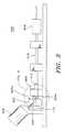
- Figure 3is a side view of the suture tipping station of Figure 2, wherein one of the tipping dies in the station is in its extended position.
- Figure 4is an enlarged view of a portion of the suture tipping station shown in Figure 2.
- Figure 5is an enlarged view of a portion of the suture tipping station shown in Figure 3.
- Figure 6shows a cross-sectional view of a length of surgical suture material which has been ultrasonically fused at its core, in accordance with a preferred embodiment of the present invention.
- Figures 7 and 8show side views of opposing tipping dies for ultrasonically forming surgical suture tips, in accordance with alternative preferred embodiments of the present invention.
- Figure 9is a cross-sectional view of a moving clamp shown in its closed state for grasping and advancing surgical suture material, in accordance with a preferred embodiment of the present invention.
- Figure 10is a cross-sectional view showing the moving clamp of Figure 9 in its open state, in accordance with a preferred embodiment of the present invention.
- Figure 11is a cross-sectional view of a stationary clamp shown in its closed state for grasping surgical suture material, in accordance with a preferred embodiment of the present invention.
- Figure 12is a cross-sectional view showing the stationary clamp of Figure 11 in its open state, in accordance with a preferred embodiment of the present invention.
- Figure 13is an isometric view of a system for tensioning a length of surgical suture material, in accordance with a preferred embodiment of the present invention.
- Figure 14is an isometric view of an optical detection system for detecting knots in surgical suture material passing through the system, in accordance with a preferred embodiment of the present invention.
- Figure 15is a further isometric view showing a knot positioned between the optical source and the optical detector ofthe knot detection system of Figure 14, in accordance with a preferred embodiment of the present invention.
- Figure 16is a cross-sectional view of Figure 15, showing a knot positioned between the optical source and the optical detector of the knot detection system of Figure 14, in accordance with a preferred embodiment of the present invention.
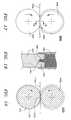
- Figure 17is a side view of a suture tipping station formed of opposing circular tipping dies, in accordance with an alternative preferred embodiment of the present invention.
- Figure 18is a cross-sectional view of the suture tipping station shown in Figure 17.
- Figure 19is a side view of a suture tipping and cutting station formed of opposing circular tipping and cutting dies, in accordance with a further alternative preferred embodiment of the present invention.
- FIG. 1there is shown a schematic diagram showing a machine 10 for ultrasonically forming and cutting surgical sutures, in accordance with a preferred embodiment of the present invention.
- a continuous length of unfinished surgical suture material 110is supplied to machine 10 from a supply spool 100 having unfinished surgical suture material 110 wound thereon.
- Unfinished surgical suture material 110 from supply spool 100is initially advanced through a tensioning assembly 200 for creating a tension in the unfinished surgical suture material, and then through a knot detector system 300 for detecting whether a knot is present in any unfinished surgical suture material 110 passing through knot detector system 300.
- the unfinished surgical suture materialis advanced to a tipping station 400, where a predetermined length of the unfinished surgical suture material 110 is ultrasonically formed into a length of surgical suture tip material.
- a cutting station 450e.g. , an automated scissor or guillotine cutter
- the suture tip materialis cut, thereby yielding a finished surgical suture having a body portion formed of unfinished surgical suture material 110 and an ultrasonically formed tip portion terminating with a cut end.
- the unfinished surgical suture material 110 from supply spool 100is advanced through machine 10 by a moving clamp 500 which is coupled to a linear actuator 550 for driving the moving clamp 500 between a starting or home position 510 on one side ofthe cutting station 450 and an end position 512 on the other side ofthe cutting station 450.
- Moving clamp 500has a grasping (or closed) state shown in Fig. 8, and a non-grasping (or open) state shown in Fig. 9.
- the moving clamp 500selectively grasps and pulls the unfinished surgical suture material 110 through machine 10 in order to facilitate the manufacture of the finished surgical sutures.
- the moving clamp 500functions to initially position and align the unfinished surgical suture material 110 within the tipping station 400.
- the moving clamp 500initially grasps or closes on the unfinished surgical suture material 110 at the home position 510.
- the linear actuator 550drives the moving clamp 500 from its home position 510 to the end position 512.
- the moving clamp 500pulls a length of the unfinished surgical suture material 110 through the station 400 and through a stationary clamp 600 positioned adjacent to the end position 512.
- the stationary clamp 600has a grasping (or closed) state which is shown in Fig. 10, and a non-grasping (or open) state shown in Fig. 11.
- the stationary clamp 600As the linear actuator 550 drives the moving clamp 500 from home position 510 to end position 512, the stationary clamp 600 is in its open state. After the moving clamp reaches its end position 512, the stationary clamp 600 grasps or closes on the unfinished surgical suture material 110 positioned within the stationary clamp 600.
- the positions of cutting station 450 and stationary clamp 600 along the length of machine 10may be adjusted in order to facilitate the creation of sutures with different lengths.
- the combined tipping and cutting station 400includes a pair of opposing tipping dies 402, 404.
- the tipping die 402has both an open state (shown in Figure 2) and a closed state (shown in Figure 3).
- the linear actuator 550drives the moving clamp 500 from home position 510 to end position 512
- the tipping die 402 in station 400is in its open position.
- the tipping die 402moves from its open (or retracted) state to its closed (or extended) state in order to facilitate the ultrasonic forming of a predetermined length of surgical suture tip material.
- tipping die 402while the tipping die 402 is in its closed state, at least one of the tipping dies 402, 404 vibrates at an ultrasonic frequency in order to form a length of surgical suture tip material.
- tipping die 402After the tipping die 402 has been in its closed state for a predetermined period of dwell time (i.e. , weld time plus hold time), tipping die 402 moves from its closed to its open state, thereby yielding a length of tipped surgical suture material positioned between dies 402, 404.
- dwell timei.e. , weld time plus hold time
- the moving clamp 500opens and releases the surgical suture material within its grasp and, with the tipping die 402 still in its closed state, the linear actuator 550 drives the moving clamp 500 from its end position 512 to its home position 510 where the moving clamp closes on a next piece of unfinished surgical suture material 110.
- the suture material at station 450is cut.
- the stationary clamp 600releases the surgical suture material within its grasp (i.e., a finished surgical suture with a cut tip), the linear actuator 550 drives the closed moving clamp back to its end position 512, and the process described above is then preferably repeated in order to manufacture further finished surgical sutures.
- the tensioning assembly 200exerts a tensioning force on the surgical suture material 110 positioned within machine 10, it is important for the moving clamp 500 to grasp or close on the surgical suture material prior to the time that the stationary clamp 600 opens, in order to prevent the tensioning assembly 200 from pulling the trailing end of the surgical suture material cut by station 450 in a reverse direction when the tipped surgical suture material is severed by station 450.
- the unfinished surgical suture material 110 used in machine 10 for manufacturing the finished suturesmay consist of any thermoplastic braided suture material such as, for example, a polyester braided suture material, or a polyamide or polyolyfin suture material.
- the unfinished surgical suture material 110 used in machine 10may consist of silk or linen material, in which case, machine 10 may be used to ultrasonically fuse silk or linen tips.
- the unfinished surgical suture material 110 used in machine 10may consist of nylon material, in which case, machine 10 may be used to ultrasonically fuse nylon tips.
- the unfinished surgical suture material 110 used in machine 10is a braided suture material formed of a polyethylene terephthalate, such as that sold by Ethicon, Inc. under the trademark Ethibond® Excel®.
- a Simatic model TI435 controller manufactured by Siemensis used to implement controller 800.
- An operator interfaceis preferably coupled to the controller 800.
- the tipping dies 402, 404 in the tipping station 400operate to ultrasonically form a predetermined length of surgical suture tip material from the unfinished surgical suture material 110 positioned within the station 400.
- the unfinished surgical suture material 110is suspended in an aligned and fixed positioned within station 400 by the stationary clamp 600 which is positioned on one side of station 400, and by the pulley 514 which is positioned on an opposing side of station 400.
- the unfinished surgical suture material 110 suspended within station 400is maintained at a preset tension by tensioning system 200.
- FIGs 2 and 3show two views of the tipping station 400. Each of the views illustrates the position of the tipping dies 402, 404 at a particular point during a suture tipping cycle.
- Fig. 2there is shown a side view of station 400, wherein the tipping die 402 is in its retracted or open position.
- Figure 2shows the position of tipping die 402 when the moving clamp 500 first reaches its end position 512.
- a cylinder 406(controlled by controller 800) drives the tipping die 402 from its retracted to its extended position. In moving the tipping die 402 between its retracted and extended positions, cylinder 406 drives tipping die 402 along the axis indicated by arrows 408.
- Figure 3shows the position of the tipping die 402 after the cylinder 406 has moved tipping die 402 to its extended position.
- a cross-sectional portion of the suture material 110 suspended within station 400is contacted by face 402a of tipping die 402 and face 404a of tipping die 404.
- the cylinder 406causes tipping die faces 402a and 404a to apply pressure to (or squeeze) the outer surfaces ofthe suture material 110 positioned between dies 402 and 404.
- about 25 PSI of pressureis applied to the outer surfaces of the suture material when die faces 402a and 404a "close-on" or squeeze the suture material positioned in station 400.
- one or both of the tipping dies 402, 404vibrate at an ultrasonic frequency for a predetermined weld time in order to form a suture tip.
- tipping die 402remains fixed in position during a dwell time (i.e., a weld time followed by a hold time) when the tipping dies 402, 404 have closed-on the unfinished surgical suture material 110, and an ultrasonic horn 412 which is connected to tipping die 404 vibrates tipping die 404 along the axis 410 at a frequency of 15 KHz to 70 KHz and an amplitude of 0.0001 to 0.010 inches for about 0.050 to 10.0 seconds in order to form the suture tip.
- horn 412vibrates tipping die 404 at a frequency of 20 KHz to 40 KHz at an amplitude of 0.004 inches for 200 ms during the suture tipping step.
- the vibrating of tipping die 404 against tipping die 402causes filaments within the interior or core 112 (shown in Figure 6) of the unfinished surgical suture material 110 (as well as filaments on the exterior surface 114 of the suture material) to fuse or weld together, thereby forming a length of surgical suture tip material between dies 402, 404.
- the cylinder 406opens the tipping die 402 by bringing it back to its initial retracted position.
- a transducer 414which is coupled to horn 412 by a booster 416 is used for vibrating horn 412.
- Booster 416functions to control the amplitude of the ultrasonic vibrations.
- a finished surgical suture formed with an ultrasonically fused suture tip as described abovehas been found to exhibit a tensile strength along the suture tip that is about 75% to 84% of the tensile strength of the body portion (i.e., the untipped portion) of the finished suture.
- the tipping parameters used to form an ultrasonically fused tipvary depending upon the diameter of the unfinished suture material 110 being supplied to machine 10. Set forth in Table I below are the preferred tipping parameters used for ultrasonically forming tips on different sizes of an unfinished braided suture material formed of a polyethylene terephthalate, such as that sold by Ethicon, Inc. under the trademark Ethibond® Excel®.
- tipping dies 402, 404are made of steel, and are coated with a non-stick substance such as TiN, Teflon® or Nedox®, in order to facilitate the release of the suture material from the tipping dies 402, 404 when such dies are opened.
- a non-stick substancesuch as TiN, Teflon® or Nedox®
- the tipping dies 402 and 404were a particular shape, it will be understood by those skilled in the art that tipping dies defining other shapes, such as those shown in Figures 7 and 8, may also be used to ultrasonically form suture tips in accordance with the present invention.
- ultrasonically tipped suture shown in Figure 6has a circular cross-section, it will be understood by those skilled in the art that ultrasonically tipped sutures having cross-sections of other shapes (e.g., polygonal) may be formed in accordance with the present invention by varying the shape and orientation of the tipping dies employed.
- System 200includes a tensioning spool 202 having a width, a weight and a circular perimeter 204 perpendicular to the width of the spool.
- the tensioning spool 202has a groove 206 in its perimeter 204 for receiving the surgical suture material 110.
- Tensioning system 200also includes a track 208 formed from a pair slots 208a, 208b extending in parallel along the length of the track 208.
- Track 208 and slots 208a, 208bare preferably positioned along a purely vertical axis, although, in alternate embodiments (not shown), track 208 and slots 208a, 208b may be aligned along an axis that includes both horizontal and vertical components.
- the slots 208a, 208bfunction to receive and guide the tensioning spool 202 along the length of track 208 during operation of system 200.
- the length of the track 208is preferably aligned perpendicularly to the width of the tensioning spool 202.
- the tensioning spool 202is suspended vertically within slots 208a, 208b by the surgical suture material 110. While the tensioning spool 202 is suspended vertically within slots 208a, 208b by the surgical suture material 110, the weight of the tensioning spool 202 exerts a corresponding tensioning force on the suture material 110 equal to the weight of spool 202. In order to vary the tension exerted on the suture material 110 during operation of system 200, additional weights 210 may be added or removed from a spool arm extending from the center of spool 202. The tension exerted on the suture material 110 during operation of system 200 preferably represents the minimum tension necessary to prevent the suture material 110 from getting "bunched-up" as it is pulled through machine 10 by moving clamp 500.
- An optical sensor 212coupled to controller 800, is provided for determining whether the pulling action of the moving clamp 500 has caused the spool 202 to be drawn upwardly within the track 208 past the height ofthe sensor 212.
- controller 800causes a motor (not shown) coupled to the supply spool 100 to unwind unfinished surgical suture material 110 from the supply spool 100.
- controller 800continues to unwind unfinished surgical suture material 110 from the supply spool 100 until the tensioning spool 202 falls below the level of optical sensor 212.
- An optical sensor 214is provided at the bottom of track 208 for determining whether there has been a break in the surgical suture material 110 or a loss of tension in the suture material within machine 10. Since, during normal operation, the tensioning spool 202 should not fall below the level of optical sensor 212, a break in suture material 110 or a loss of suture tension within machine 10 will be signaled by sensor 214 if the sensor determines that the tensioning spool 202 has fallen to the level of the sensor 214.
- Knot detector system 300includes an optical light source 302 for directing a plane of light 304 at an optical light detector 306 when surgical suture material 110 is positioned between the optical light source 302 and the optical light detector 306.
- the optical light source 302is preferably formed of a plurality of optical fibers 302a having their terminating ends aligned along the optical plane 304.
- Controller 800is coupled to an output ofthe optical light detector 306 for processing the signals output by detector 306 and determining whether a knot exists in the suture material 110 positioned between the light source 302 and light detector 306. More particularly, by comparing a magnitude of a shadow 308 cast on the optical light detector 306 by the suture material 110 against a predetermined threshold, controller 800 determines whether or not a knot exists in the suture material 110 positioned between the light source 302 and light detector 306.
- the predetermined threshold used in this comparisoncorresponds to a magnitude of a shadow 308a cast on the optical light detector 306 by an unknoted cross-section of suture material 110.
- controller 800will determine that a knot exists in the suture material 110 passing through system 300 only if the magnitude of the shadow cast on light detector 306 by suture material 110 exceeds by at least 30% the magnitude of a shadow 308a cast on the optical light detector 306 by an unknoted cross-section of suture material 110.
- machine 10was used to manufacture a finished surgical suture having a length that was less than length ofthe linear actuator 550
- machine 10may also be used in an extended length suture mode, described below, in order to make finished surgical sutures which are longer than linear actuator 550.
- the moving clamp 500initially grasps or closes on the unfinished surgical suture material 110 at the home position 510.
- the linear actuator 550drives the moving clamp 500 from its home position 510 to the end position 512.
- the linear actuator 550drives moving clamp 500 from its home position 510 to its position 512
- the moving clamp 500pulls a length of the unfinished surgical suture material 110 through the tipping station 400, cutting station 450 and through the stationary clamp 600.
- the stationary clamp 600grasps or closes on the unfinished surgical suture material 110 positioned within the stationary clamp 600.
- the moving clamp 500then releases the unfinished surgical suture material 110 in its grasp.
- the linear actuator 550drives the moving clamp 500 from its end position 512 to its home position 510, where the moving clamp 500 again grasps or closes on the unfinished surgical suture material 110 at the home position 510.
- the stationary clamp 600After the moving clamp 500 grasps the unfinished surgical suture material 110 at the home position 510 for the second time, the stationary clamp 600 opens. Thereafter, while the moving clamp 500 remains in its grasping or closed state and the stationary clamp 600 remains in its open state, the linear actuator 550 again drives the moving clamp 500 from its home position 510 to the end position 512. After the moving clamp 500 reaches its end position 512 for the second time, the stationary clamp 600 again grasps or closes on the unfinished surgical suture material 110 positioned within the stationary clamp 600.
- the dies 402, 404 in the tipping station 400function as described above to ultrasonically form a length of surgical suture tip material positioned within the station 400.
- the stationary clamp 600releases the surgical suture material within its grasp.
- a finished surgical suturehaving an ultrasonically formed and cut tip results. Since the moving clamp 500 pulled the suture material 110 two times consecutively before the tipping station 400 formed the suture tip, the resulting finished surgical suture produced by the extended length suture mode may have a length which is greater than the length of the linear actuator 550.
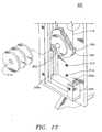
- FIG. 17 and 18there are shown side and cross-sectional views of an alternative suture tipping station 400a formed of opposing circular tipping dies 440, 450 for continuously tipping unfinished surgical suture material 110a, in accordance with an alternative preferred embodiment of the present invention.
- Tipping die 440contains a notch 403 around a portion of its perimeter
- tipping die 450contains a corresponding groove 405 positioned about its perimeter.
- notch 403is sized such that pressure is applied to the exterior surface of suture material 110a when suture material 110a is between notch 403 and the lower end of groove 405.
- Tipping dies 440, 450are coupled to mechanical actuators (not shown) which continually rotate the dies 440, 450 in the direction of the arrows shown in Figure 17.
- an ultrasonic hornalso not shown vibrates tipping die 440 against tipping die 450 at a frequency of 15 KHz to 70 KHz (and preferably 20 KHz to 40 KHz) and an amplitude of 0.0001 to 0.010 inches in order to continuously form suture tip material.
- Station 400amay be substituted for station 400 in Figure 1, in order to configure machine 10 to continuously produce surgical sutures with ultrasonically formed tips, in accordance with the present invention.
- FIG. 19there is shown a side view of a suture tipping and cutting station 400b formed of opposing circular tipping and cutting dies 440a, 450 for continuously tipping and cutting unfinished surgical suture material 110, in accordance with a further alternative preferred embodiment of the present invention.
- Die 440ais substantially the same as die 440, except that die 440a includes a cutting point 403b for cutting a suture tip end portion during the rotation of die 440a against 450.
- Station 400bfunctions substantially the same as station 400a, except that station 400b may be used to both form and cut suture tips in a continuous manner.
- station 400bSince the cutting performed by station 400b is accomplished using a cutting point 403b which vibrates at an ultrasonic frequency, a suture tip is simultaneously both cut and sealed by station 400b. In addition, the ultrasonic cutting action of point 403b yields a cut suture tip with a lead angle which facilitates the insertion of the cut suture tip into a drilled needle.
- dies 440a and 450function to both tip and cut surgical suture material 110, it will be understood by those skilled in the art that two separate pairs of circular dies may be employed in series to respectively perform the tipping and cutting operations.
Landscapes
- Engineering & Computer Science (AREA)
- Mechanical Engineering (AREA)
- Health & Medical Sciences (AREA)
- Life Sciences & Earth Sciences (AREA)
- Surgery (AREA)
- Medical Informatics (AREA)
- Biomedical Technology (AREA)
- Heart & Thoracic Surgery (AREA)
- Nuclear Medicine, Radiotherapy & Molecular Imaging (AREA)
- Molecular Biology (AREA)
- Animal Behavior & Ethology (AREA)
- General Health & Medical Sciences (AREA)
- Public Health (AREA)
- Veterinary Medicine (AREA)
- Physics & Mathematics (AREA)
- Fluid Mechanics (AREA)
- Materials For Medical Uses (AREA)
- Surgical Instruments (AREA)
Abstract
Description
More particularly, the present invention is directed to automated systems for forming surgicalsuture tips through the use of ultrasonic welding.
| SIZE | 0 | 2/0 | 3/0 | 4/0 | 5/0 |
| Tipping Die Pressure (in PSI) | 80 | 25 | 25 | 15 | 5 |
| Tipping Die Vibration Frequency (in KHz) | 15-70 | 15-70 | 15-70 | 15-70 | 15-70 |
| Tipping Die Weld Time (in seconds) | 0.900-10.0 | 0.400-5.0 | 0.100-5.0 | 0.025-2.0 | 0.025-2.0 |
| Tipping Die Hold Time (in seconds) | 0.100-0.500 | 0.100-0.500 | 0.100-0.500 | 0.100-0.500 | 0.100-0.500 |
Claims (10)
- A multifilament surgical suture comprised of a body portionand a tip portion which is adjacent to said body portion,said surgical suture being formed of a plurality offilaments, said tip portion having a tip length, a tipcross-section perpendicular to said tip length, and a tipcore positioned at a center of said tip cross-section andalong said tip length, wherein said filaments positioned atsaid tip core are ultrasonically fused together.
- The surgical suture of claim 1, wherein said tipportion has a tensile strength that is at least seventy-fivepercent, and preferably 75% to 84%, of the tensilestrength of said body portion of said suture.
- The surgical suture of claim 1 or claim 2, whereinsaid tip cross-section is circular.
- The surgical suture of any one of claims 1 to 3,wherein said multifilament surgical suture is formed fromsilk or linen.
- An apparatus for ultrasonically forming a surgicalsuture tip from a length of unfinished surgical suturematerial, comprising:(A) a first tipping die having a first facecontacting a portion of said length of said unfinishedsurgical suture material;(B) a second tipping die having a second face;(C) at least one mechanical actuator for moving saidfirst face of said first tipping die toward said second faceof said second tipping die;(D) a second actuator for vibrating at least one ofsaid first and second tipping dies at an ultrasonicfrequency of about 15 KHz to 70 KHz; andOPTIONALLY (E) means for tensioning said length ofsaid unfinished surgical material.
- The apparatus of claim 5, wherein said second actuatoris coupled to said second tipping die and is formed of anacoustic horn.
- The apparatus of claim 5 or claim 6, wherein saidfirst face has a cutting notch therein, and wherein saidsecond actuator is further provided for cutting saidsurgical suture tip by vibrating said cutting notch at saidultrasonic frequency.
- The apparatus of any one of claims 5 to 7, whereinsaid at least one mechanical actuator is formed from acylinder coupled to said first tipping die for moving saidfirst tipping die from its open to its closed position.
- The apparatus of any one of claims 5 to 8, whereinsaid first tipping die is circular and a tipping groove ispositioned around a perimeter of said first tipping die,wherein said second tipping die is circular and a tippingnotch is positioned around a portion of a perimeter of saidsecond tipping die, and wherein said at least one mechanicalactuator is provided for turning said first and secondtipping dies in order to move said first face of said firsttipping die toward said second face of said second tippingdie.
- A method of ultrasonically forming a surgical suturetip from a length of unfinished surgical suture material,comprising the steps of:(A) positioning said length of said unfinishedsurgical suture material at a location between a first faceof a first tipping die and a second face of a second tippingdie; and(B) after said positioning step, forming saidsurgical suture tip by vibrating at least one of said firstand second tipping dies at an ultrasonic frequency of about15 KHz to 70 KHz.
Applications Claiming Priority (2)
| Application Number | Priority Date | Filing Date | Title |
|---|---|---|---|
| US739561 | 1991-08-02 | ||
| US08/739,561US5891166A (en) | 1996-10-30 | 1996-10-30 | Surgical suture having an ultrasonically formed tip, and apparatus and method for making same |
Publications (2)
| Publication Number | Publication Date |
|---|---|
| EP0839499A1true EP0839499A1 (en) | 1998-05-06 |
| EP0839499B1 EP0839499B1 (en) | 2003-09-24 |
Family
ID=24972866
Family Applications (1)
| Application Number | Title | Priority Date | Filing Date |
|---|---|---|---|
| EP97308631AExpired - LifetimeEP0839499B1 (en) | 1996-10-30 | 1997-10-29 | Surgical suture having an ultrasonically formed tip, and apparatus and method for making same |
Country Status (3)
| Country | Link |
|---|---|
| US (2) | US5891166A (en) |
| EP (1) | EP0839499B1 (en) |
| DE (1) | DE69725086T2 (en) |
Cited By (10)
| Publication number | Priority date | Publication date | Assignee | Title |
|---|---|---|---|---|
| EP1050273A1 (en)* | 1999-05-04 | 2000-11-08 | Ethicon, Inc. | Surgical suture having an ultrasonically formed tip |
| US6730111B2 (en) | 1996-10-30 | 2004-05-04 | Semyon Shchervinsky | Surgical tipping apparatus |
| WO2004100801A3 (en)* | 2003-05-13 | 2005-05-12 | Quill Medical Inc | Apparatus for forming barbs on a suture |
| US9675341B2 (en) | 2010-11-09 | 2017-06-13 | Ethicon Inc. | Emergency self-retaining sutures and packaging |
| US9955962B2 (en) | 2010-06-11 | 2018-05-01 | Ethicon, Inc. | Suture delivery tools for endoscopic and robot-assisted surgery and methods |
| US10420546B2 (en) | 2010-05-04 | 2019-09-24 | Ethicon, Inc. | Self-retaining systems having laser-cut retainers |
| US10441270B2 (en) | 2008-11-03 | 2019-10-15 | Ethicon, Inc. | Length of self-retaining suture and method and device for using the same |
| US10492780B2 (en) | 2011-03-23 | 2019-12-03 | Ethicon, Inc. | Self-retaining variable loop sutures |
| US10548592B2 (en) | 2004-05-14 | 2020-02-04 | Ethicon, Inc. | Suture methods and devices |
| US11007296B2 (en) | 2010-11-03 | 2021-05-18 | Ethicon, Inc. | Drug-eluting self-retaining sutures and methods relating thereto |
Families Citing this family (56)
| Publication number | Priority date | Publication date | Assignee | Title |
|---|---|---|---|---|
| US8795332B2 (en) | 2002-09-30 | 2014-08-05 | Ethicon, Inc. | Barbed sutures |
| US6241747B1 (en) | 1993-05-03 | 2001-06-05 | Quill Medical, Inc. | Barbed Bodily tissue connector |
| US5891166A (en)* | 1996-10-30 | 1999-04-06 | Ethicon, Inc. | Surgical suture having an ultrasonically formed tip, and apparatus and method for making same |
| US5931855A (en) | 1997-05-21 | 1999-08-03 | Frank Hoffman | Surgical methods using one-way suture |
| US20050216059A1 (en) | 2002-09-05 | 2005-09-29 | Bonutti Peter M | Method and apparatus for securing a suture |
| US6045551A (en) | 1998-02-06 | 2000-04-04 | Bonutti; Peter M. | Bone suture |
| US6368343B1 (en)* | 2000-03-13 | 2002-04-09 | Peter M. Bonutti | Method of using ultrasonic vibration to secure body tissue |
| US6592609B1 (en)* | 1999-08-09 | 2003-07-15 | Bonutti 2003 Trust-A | Method and apparatus for securing tissue |
| US6447516B1 (en) | 1999-08-09 | 2002-09-10 | Peter M. Bonutti | Method of securing tissue |
| US6635073B2 (en) | 2000-05-03 | 2003-10-21 | Peter M. Bonutti | Method of securing body tissue |
| US7094251B2 (en) | 2002-08-27 | 2006-08-22 | Marctec, Llc. | Apparatus and method for securing a suture |
| US9138222B2 (en) | 2000-03-13 | 2015-09-22 | P Tech, Llc | Method and device for securing body tissue |
| US8932330B2 (en)* | 2000-03-13 | 2015-01-13 | P Tech, Llc | Method and device for securing body tissue |
| US7329263B2 (en)* | 2000-03-13 | 2008-02-12 | Marctec, Llc | Method and device for securing body tissue |
| US7056331B2 (en) | 2001-06-29 | 2006-06-06 | Quill Medical, Inc. | Suture method |
| US6848152B2 (en) | 2001-08-31 | 2005-02-01 | Quill Medical, Inc. | Method of forming barbs on a suture and apparatus for performing same |
| US6719765B2 (en) | 2001-12-03 | 2004-04-13 | Bonutti 2003 Trust-A | Magnetic suturing system and method |
| US9155544B2 (en) | 2002-03-20 | 2015-10-13 | P Tech, Llc | Robotic systems and methods |
| US6773450B2 (en) | 2002-08-09 | 2004-08-10 | Quill Medical, Inc. | Suture anchor and method |
| US8100940B2 (en) | 2002-09-30 | 2012-01-24 | Quill Medical, Inc. | Barb configurations for barbed sutures |
| US20040088003A1 (en) | 2002-09-30 | 2004-05-06 | Leung Jeffrey C. | Barbed suture in combination with surgical needle |
| US7497864B2 (en) | 2003-04-30 | 2009-03-03 | Marctec, Llc. | Tissue fastener and methods for using same |
| US20080039873A1 (en)* | 2004-03-09 | 2008-02-14 | Marctec, Llc. | Method and device for securing body tissue |
| US9271766B2 (en) | 2004-10-26 | 2016-03-01 | P Tech, Llc | Devices and methods for stabilizing tissue and implants |
| US9463012B2 (en) | 2004-10-26 | 2016-10-11 | P Tech, Llc | Apparatus for guiding and positioning an implant |
| US20060089646A1 (en) | 2004-10-26 | 2006-04-27 | Bonutti Peter M | Devices and methods for stabilizing tissue and implants |
| US9173647B2 (en) | 2004-10-26 | 2015-11-03 | P Tech, Llc | Tissue fixation system |
| US9089323B2 (en) | 2005-02-22 | 2015-07-28 | P Tech, Llc | Device and method for securing body tissue |
| US11253296B2 (en) | 2006-02-07 | 2022-02-22 | P Tech, Llc | Methods and devices for intracorporeal bonding of implants with thermal energy |
| US11278331B2 (en) | 2006-02-07 | 2022-03-22 | P Tech Llc | Method and devices for intracorporeal bonding of implants with thermal energy |
| US9439642B2 (en) | 2006-02-07 | 2016-09-13 | P Tech, Llc | Methods and devices for utilizing bondable materials |
| US7967820B2 (en) | 2006-02-07 | 2011-06-28 | P Tech, Llc. | Methods and devices for trauma welding |
| US8496657B2 (en) | 2006-02-07 | 2013-07-30 | P Tech, Llc. | Methods for utilizing vibratory energy to weld, stake and/or remove implants |
| US11246638B2 (en) | 2006-05-03 | 2022-02-15 | P Tech, Llc | Methods and devices for utilizing bondable materials |
| US8617185B2 (en) | 2007-02-13 | 2013-12-31 | P Tech, Llc. | Fixation device |
| US8915943B2 (en) | 2007-04-13 | 2014-12-23 | Ethicon, Inc. | Self-retaining systems for surgical procedures |
| ES2398779T3 (en) | 2007-09-27 | 2013-03-21 | Ethicon Llc | Self-retaining sutures that include tissue retention elements with enhanced strength |
| US8916077B1 (en) | 2007-12-19 | 2014-12-23 | Ethicon, Inc. | Self-retaining sutures with retainers formed from molten material |
| WO2009086172A2 (en) | 2007-12-19 | 2009-07-09 | Angiotech Pharmaceuticals, Inc. | Self-retaining sutures with heat-contact mediated retainers |
| US8118834B1 (en) | 2007-12-20 | 2012-02-21 | Angiotech Pharmaceuticals, Inc. | Composite self-retaining sutures and method |
| US8875607B2 (en) | 2008-01-30 | 2014-11-04 | Ethicon, Inc. | Apparatus and method for forming self-retaining sutures |
| US8615856B1 (en) | 2008-01-30 | 2013-12-31 | Ethicon, Inc. | Apparatus and method for forming self-retaining sutures |
| ES2706295T3 (en) | 2008-02-21 | 2019-03-28 | Ethicon Llc | Method and apparatus for raising retainers in self-retaining sutures |
| US8216273B1 (en) | 2008-02-25 | 2012-07-10 | Ethicon, Inc. | Self-retainers with supporting structures on a suture |
| US8641732B1 (en) | 2008-02-26 | 2014-02-04 | Ethicon, Inc. | Self-retaining suture with variable dimension filament and method |
| SG188784A1 (en) | 2008-04-15 | 2013-04-30 | Ethicon Llc | Self-retaining sutures with bi-directional retainers or uni-directional retainers |
| US20090259252A1 (en)* | 2008-04-15 | 2009-10-15 | Kennedy John J | Apparatus For The Joining Of Tissue Having Integral Penetrating End |
| US8961560B2 (en) | 2008-05-16 | 2015-02-24 | Ethicon, Inc. | Bidirectional self-retaining sutures with laser-marked and/or non-laser marked indicia and methods |
| US20130172931A1 (en) | 2011-06-06 | 2013-07-04 | Jeffrey M. Gross | Methods and devices for soft palate tissue elevation procedures |
| US10076377B2 (en) | 2013-01-05 | 2018-09-18 | P Tech, Llc | Fixation systems and methods |
| US10385488B1 (en) | 2015-02-03 | 2019-08-20 | Stryker Corporation | Suture of varying cross-section and methods of manufacture and use |
| US10323342B1 (en) | 2015-03-16 | 2019-06-18 | Stryker Corporation | Braided filament having flat morphology and methods of manufacture and use |
| US10058393B2 (en) | 2015-10-21 | 2018-08-28 | P Tech, Llc | Systems and methods for navigation and visualization |
| CH714251B1 (en) | 2017-10-16 | 2022-01-14 | Sonderegger Eng Ag | Rolling unit for use in a thread cutting device and method for removing gas pockets from thread material. |
| US11224421B2 (en)* | 2018-11-28 | 2022-01-18 | Ethicon, Inc. | Systems, devices and methods of making surgical sutures having reformed, reduced diameter tips |
| KR102668392B1 (en)* | 2023-09-11 | 2024-05-23 | 주식회사 현대메디텍 | Suture Processing Machine And Method Using Ultrasonic Waves |
Citations (5)
| Publication number | Priority date | Publication date | Assignee | Title |
|---|---|---|---|---|
| US4075046A (en)* | 1976-10-12 | 1978-02-21 | Thomas Taylor & Sons, Inc. | Tipped lace |
| US4377427A (en)* | 1979-11-20 | 1983-03-22 | R. George S.A. | Process for the manufacture of locks of hair from synthetic fibers, device for putting this process into operation and locks of hair thus obtained |
| US4806737A (en) | 1987-07-30 | 1989-02-21 | American Cyanamid Company | Apparatus for manufacturing a surgical suture |
| US4832025A (en) | 1987-07-30 | 1989-05-23 | American Cyanamid Company | Thermoplastic surgical suture with a melt fused length |
| US5226336A (en) | 1987-07-30 | 1993-07-13 | American Cyanamid Company | Apparatus for manufacturing a surgical suture |
Family Cites Families (38)
| Publication number | Priority date | Publication date | Assignee | Title |
|---|---|---|---|---|
| US1492821A (en)* | 1922-09-29 | 1924-05-06 | Mendel P Weinbach | Antifreezing device |
| US1665216A (en)* | 1925-07-30 | 1928-04-10 | Harry D Morton | Method of making needle-and-suture assembly |
| US2173789A (en)* | 1935-12-05 | 1939-09-19 | Nikles Paul | Method of producing stapled fibers |
| GB568675A (en)* | 1943-03-12 | 1945-04-16 | George Frederick Rayner | Process of making composite yarns, and the composite yarns so produced |
| US2803109A (en)* | 1954-01-04 | 1957-08-20 | Universal Winding Co | Method of processing thermoplastic yarns |
| CH759162D (en)* | 1961-07-13 | |||
| US3165958A (en)* | 1962-03-14 | 1965-01-19 | Grace W R & Co | Dispensing apparatus for waximpregnated material |
| US3272682A (en)* | 1962-08-13 | 1966-09-13 | Cavitron Ultrasonics Inc | Apparatus for joining thermoplastic sheet material with ultrasonic rotary vibrators |
| US3317924A (en)* | 1963-05-27 | 1967-05-09 | Veen Harry H Le | Vascular prostheses |
| GB996908A (en)* | 1964-04-15 | 1965-06-30 | Chemcell 1963 Ltd | Improvements relating to heat stretching thermo-plastic yarns and filaments |
| US3388030A (en)* | 1965-03-26 | 1968-06-11 | Monsanto Co | Twistless synthetic multifilament yarns and process for making the same |
| US3376698A (en)* | 1965-08-02 | 1968-04-09 | Tmm Research Ltd | Production of stretch or bulked textile yarns |
| US3449549A (en)* | 1966-03-29 | 1969-06-10 | Kokusai Electric Co Ltd | Heat treatment apparatus for a travelling yarn or yarns |
| US3479670A (en)* | 1966-10-19 | 1969-11-25 | Ethicon Inc | Tubular prosthetic implant having helical thermoplastic wrapping therearound |
| US3564958A (en)* | 1967-07-17 | 1971-02-23 | Leesona Corp | Yarn handling apparatus |
| US3657056A (en)* | 1967-12-11 | 1972-04-18 | Ultrasonic Systems | Ultrasonic suturing apparatus |
| US3807270A (en)* | 1968-11-06 | 1974-04-30 | Rieter Ag Maschf | Apparatus for cutting a thread on a draw-spin-winding machine |
| US3642010A (en)* | 1969-12-17 | 1972-02-15 | Ultrasonic Systems | Ultrasonic method for hair joining |
| US3736646A (en)* | 1971-10-18 | 1973-06-05 | American Cyanamid Co | Method of attaching surgical needles to multifilament polyglycolic acid absorbable sutures |
| TR17343A (en)* | 1972-05-31 | 1975-03-24 | Ethicon Inc | SUETUER THAT CAN BE RELEASED BY CONTROL |
| US3835912A (en)* | 1973-06-25 | 1974-09-17 | S K S Ltd | Method of joining a filament to a metal rod |
| US3980177A (en)* | 1973-10-26 | 1976-09-14 | Johnson & Johnson | Controlled release suture |
| US3981307A (en)* | 1974-07-01 | 1976-09-21 | Ethicon, Inc. | Thermal attachment of surgical sutures to needles |
| US3943933A (en)* | 1974-09-25 | 1976-03-16 | Ethicon, Inc. | Suture with radiation degradation near needle-suture junction |
| US4014648A (en)* | 1974-11-08 | 1977-03-29 | Microfibres, Inc. | In-line flock cutting process |
| US3949756A (en)* | 1974-11-20 | 1976-04-13 | Ethicon, Inc. | Sutures with notch near needle-suture junction |
| US4041814A (en)* | 1975-11-03 | 1977-08-16 | Morley Brotman | Method and device for dispensing portions of a chain |
| DE2724892C2 (en)* | 1977-06-02 | 1987-03-26 | Lucke-Apparate-Bau GmbH, 7947 Mengen | Device for cutting a yarn on ball winding machines |
| SU950830A1 (en)* | 1980-01-10 | 1982-08-15 | Ивановское Специальное Конструкторское Бюро Красильно-Отделочного Оборудования | Cylinder for thermal working of textile materials |
| US4358976A (en)* | 1981-01-26 | 1982-11-16 | Bel Air Tool Corp. | Chain cutting machine |
| CA1197963A (en)* | 1981-07-22 | 1985-12-17 | Michito Matsumoto | Apparatus and method for heating heat-shrinkable tubes |
| US4470941A (en)* | 1982-06-02 | 1984-09-11 | Bioresearch Inc. | Preparation of composite surgical sutures |
| EP0119287B1 (en)* | 1983-03-19 | 1988-01-07 | Ackermann-Göggingen Ag | Heat resistant sewing thread and method for its production |
| US4510934A (en)* | 1983-05-13 | 1985-04-16 | Batra Subhash K | Suture |
| US4669474A (en)* | 1984-01-12 | 1987-06-02 | Minnesota Mining And Manufacturing Company | Absorbable nerve repair device and method |
| US4716801A (en)* | 1986-08-15 | 1988-01-05 | Eastman Kodak Company | Rapid cut-off apparatus for high speed moving yarn |
| US5507777A (en)* | 1994-10-07 | 1996-04-16 | United States Surgical Corporation | Method and apparatus for treating a portion of a suture and forming a suture tip for attachment to a needle |
| US5891166A (en)* | 1996-10-30 | 1999-04-06 | Ethicon, Inc. | Surgical suture having an ultrasonically formed tip, and apparatus and method for making same |
- 1996
- 1996-10-30USUS08/739,561patent/US5891166A/ennot_activeExpired - Lifetime
- 1997
- 1997-10-29EPEP97308631Apatent/EP0839499B1/ennot_activeExpired - Lifetime
- 1997-10-29DEDE69725086Tpatent/DE69725086T2/ennot_activeExpired - Fee Related
- 1999
- 1999-03-26USUS09/277,670patent/US6035916A/ennot_activeExpired - Lifetime
Patent Citations (5)
| Publication number | Priority date | Publication date | Assignee | Title |
|---|---|---|---|---|
| US4075046A (en)* | 1976-10-12 | 1978-02-21 | Thomas Taylor & Sons, Inc. | Tipped lace |
| US4377427A (en)* | 1979-11-20 | 1983-03-22 | R. George S.A. | Process for the manufacture of locks of hair from synthetic fibers, device for putting this process into operation and locks of hair thus obtained |
| US4806737A (en) | 1987-07-30 | 1989-02-21 | American Cyanamid Company | Apparatus for manufacturing a surgical suture |
| US4832025A (en) | 1987-07-30 | 1989-05-23 | American Cyanamid Company | Thermoplastic surgical suture with a melt fused length |
| US5226336A (en) | 1987-07-30 | 1993-07-13 | American Cyanamid Company | Apparatus for manufacturing a surgical suture |
Cited By (17)
| Publication number | Priority date | Publication date | Assignee | Title |
|---|---|---|---|---|
| US6730111B2 (en) | 1996-10-30 | 2004-05-04 | Semyon Shchervinsky | Surgical tipping apparatus |
| EP1050273A1 (en)* | 1999-05-04 | 2000-11-08 | Ethicon, Inc. | Surgical suture having an ultrasonically formed tip |
| WO2004100801A3 (en)* | 2003-05-13 | 2005-05-12 | Quill Medical Inc | Apparatus for forming barbs on a suture |
| AU2004238371B2 (en)* | 2003-05-13 | 2011-10-20 | Ethicon Llc | Apparatus for forming barbs on a suture |
| US10548592B2 (en) | 2004-05-14 | 2020-02-04 | Ethicon, Inc. | Suture methods and devices |
| US11723654B2 (en) | 2004-05-14 | 2023-08-15 | Ethicon, Inc. | Suture methods and devices |
| US10779815B2 (en) | 2004-05-14 | 2020-09-22 | Ethicon, Inc. | Suture methods and devices |
| US10441270B2 (en) | 2008-11-03 | 2019-10-15 | Ethicon, Inc. | Length of self-retaining suture and method and device for using the same |
| US11234689B2 (en) | 2008-11-03 | 2022-02-01 | Ethicon, Inc. | Length of self-retaining suture and method and device for using the same |
| US10420546B2 (en) | 2010-05-04 | 2019-09-24 | Ethicon, Inc. | Self-retaining systems having laser-cut retainers |
| US10952721B2 (en) | 2010-05-04 | 2021-03-23 | Ethicon, Inc. | Laser cutting system and methods for creating self-retaining sutures |
| US11234692B2 (en) | 2010-05-04 | 2022-02-01 | Cilag Gmbh International | Self-retaining system having laser-cut retainers |
| US9955962B2 (en) | 2010-06-11 | 2018-05-01 | Ethicon, Inc. | Suture delivery tools for endoscopic and robot-assisted surgery and methods |
| US11007296B2 (en) | 2010-11-03 | 2021-05-18 | Ethicon, Inc. | Drug-eluting self-retaining sutures and methods relating thereto |
| US9675341B2 (en) | 2010-11-09 | 2017-06-13 | Ethicon Inc. | Emergency self-retaining sutures and packaging |
| US11690614B2 (en) | 2011-03-23 | 2023-07-04 | Ethicon, Inc. | Self-retaining variable loop sutures |
| US10492780B2 (en) | 2011-03-23 | 2019-12-03 | Ethicon, Inc. | Self-retaining variable loop sutures |
Also Published As
| Publication number | Publication date |
|---|---|
| DE69725086T2 (en) | 2004-07-08 |
| EP0839499B1 (en) | 2003-09-24 |
| DE69725086D1 (en) | 2003-10-30 |
| US5891166A (en) | 1999-04-06 |
| US6035916A (en) | 2000-03-14 |
Similar Documents
| Publication | Publication Date | Title |
|---|---|---|
| EP0839499B1 (en) | Surgical suture having an ultrasonically formed tip, and apparatus and method for making same | |
| US6126676A (en) | Surgical tipping apparatus | |
| US6024757A (en) | Method for cutting a surgical suture tip | |
| US20220117601A1 (en) | System and Method For Making Tapered Looped Suture | |
| US4032382A (en) | Method and apparatus for splicing thermoplastic monofilament material by high frequency vibratory energy | |
| CA2029668A1 (en) | Sterile surgical needle-suture combination | |
| US6730111B2 (en) | Surgical tipping apparatus | |
| JP5627918B2 (en) | System and method for making a tapered loop suture | |
| EP0806179B1 (en) | Apparatus with moving clamp for making surgical sutures, and method for using same | |
| EP1266627B1 (en) | Surgical suture having a thermally formed tip | |
| EP0806177B1 (en) | Combined apparatus for heating and cutting a surgical suture tip, and method for using same | |
| US6035751A (en) | Method for cutting a surgical suture at two locations | |
| US6001121A (en) | Surgical suture having a thermally formed tip, and apparatus and method for making same | |
| EP0806181B1 (en) | Apparatus and method for cutting a surgical suture at two locations | |
| EP0806178B1 (en) | Apparatus and method for forming a cut end of a surgical suture tip | |
| US20110180196A1 (en) | System And Method For Making Tapered Looped Suture | |
| JP2001152440A (en) | Monofilament splicer | |
| CA2871660A1 (en) | System and method for making tapered looped suture | |
| MXPA97003487A (en) | Surgical suture that has a terminally formed tip, and apparatus and method to make my |
Legal Events
| Date | Code | Title | Description |
|---|---|---|---|
| PUAI | Public reference made under article 153(3) epc to a published international application that has entered the european phase | Free format text:ORIGINAL CODE: 0009012 | |
| AK | Designated contracting states | Kind code of ref document:A1 Designated state(s):DE GB | |
| 17P | Request for examination filed | Effective date:19981016 | |
| AKX | Designation fees paid | Free format text:DE GB | |
| RBV | Designated contracting states (corrected) | Designated state(s):DE GB | |
| 17Q | First examination report despatched | Effective date:20020206 | |
| GRAH | Despatch of communication of intention to grant a patent | Free format text:ORIGINAL CODE: EPIDOS IGRA | |
| GRAS | Grant fee paid | Free format text:ORIGINAL CODE: EPIDOSNIGR3 | |
| GRAA | (expected) grant | Free format text:ORIGINAL CODE: 0009210 | |
| AK | Designated contracting states | Kind code of ref document:B1 Designated state(s):DE GB | |
| REG | Reference to a national code | Ref country code:GB Ref legal event code:FG4D | |
| REF | Corresponds to: | Ref document number:69725086 Country of ref document:DE Date of ref document:20031030 Kind code of ref document:P | |
| PLBE | No opposition filed within time limit | Free format text:ORIGINAL CODE: 0009261 | |
| STAA | Information on the status of an ep patent application or granted ep patent | Free format text:STATUS: NO OPPOSITION FILED WITHIN TIME LIMIT | |
| 26N | No opposition filed | Effective date:20040625 | |
| PGFP | Annual fee paid to national office [announced via postgrant information from national office to epo] | Ref country code:GB Payment date:20061025 Year of fee payment:10 | |
| PGFP | Annual fee paid to national office [announced via postgrant information from national office to epo] | Ref country code:DE Payment date:20061026 Year of fee payment:10 | |
| GBPC | Gb: european patent ceased through non-payment of renewal fee | Effective date:20071029 | |
| PG25 | Lapsed in a contracting state [announced via postgrant information from national office to epo] | Ref country code:DE Free format text:LAPSE BECAUSE OF NON-PAYMENT OF DUE FEES Effective date:20080501 | |
| PG25 | Lapsed in a contracting state [announced via postgrant information from national office to epo] | Ref country code:GB Free format text:LAPSE BECAUSE OF NON-PAYMENT OF DUE FEES Effective date:20071029 |