EP0838304B1 - Mobile precision boring tool - Google Patents
Mobile precision boring toolDownload PDFInfo
- Publication number
- EP0838304B1 EP0838304B1EP97122729AEP97122729AEP0838304B1EP 0838304 B1EP0838304 B1EP 0838304B1EP 97122729 AEP97122729 AEP 97122729AEP 97122729 AEP97122729 AEP 97122729AEP 0838304 B1EP0838304 B1EP 0838304B1
- Authority
- EP
- European Patent Office
- Prior art keywords
- tool
- feed
- spindle
- drive
- tool spindle
- Prior art date
- Legal status (The legal status is an assumption and is not a legal conclusion. Google has not performed a legal analysis and makes no representation as to the accuracy of the status listed.)
- Expired - Lifetime
Links
- 238000005553drillingMethods0.000claimsdescription13
- 238000005259measurementMethods0.000claimsdescription5
- 238000006073displacement reactionMethods0.000claimsdescription3
- 230000001105regulatory effectEffects0.000claimsdescription3
- 230000001953sensory effectEffects0.000claims1
- 238000003754machiningMethods0.000description6
- 239000000523sampleSubstances0.000description5
- 238000012545processingMethods0.000description3
- 230000005540biological transmissionEffects0.000description2
- 230000001419dependent effectEffects0.000description2
- 238000001514detection methodMethods0.000description2
- 239000000314lubricantSubstances0.000description2
- 239000000463materialSubstances0.000description2
- 238000013459approachMethods0.000description1
- 238000010276constructionMethods0.000description1
- 238000011156evaluationMethods0.000description1
- 230000002349favourable effectEffects0.000description1
- 230000003993interactionEffects0.000description1
- 238000012423maintenanceMethods0.000description1
- 238000012544monitoring processMethods0.000description1
- 230000035515penetrationEffects0.000description1
- 230000002093peripheral effectEffects0.000description1
- 230000003134recirculating effectEffects0.000description1
Images


Classifications
- G—PHYSICS
- G05—CONTROLLING; REGULATING
- G05B—CONTROL OR REGULATING SYSTEMS IN GENERAL; FUNCTIONAL ELEMENTS OF SUCH SYSTEMS; MONITORING OR TESTING ARRANGEMENTS FOR SUCH SYSTEMS OR ELEMENTS
- G05B19/00—Programme-control systems
- G05B19/02—Programme-control systems electric
- G05B19/18—Numerical control [NC], i.e. automatically operating machines, in particular machine tools, e.g. in a manufacturing environment, so as to execute positioning, movement or co-ordinated operations by means of programme data in numerical form
- G05B19/19—Numerical control [NC], i.e. automatically operating machines, in particular machine tools, e.g. in a manufacturing environment, so as to execute positioning, movement or co-ordinated operations by means of programme data in numerical form characterised by positioning or contouring control systems, e.g. to control position from one programmed point to another or to control movement along a programmed continuous path
- G05B19/21—Numerical control [NC], i.e. automatically operating machines, in particular machine tools, e.g. in a manufacturing environment, so as to execute positioning, movement or co-ordinated operations by means of programme data in numerical form characterised by positioning or contouring control systems, e.g. to control position from one programmed point to another or to control movement along a programmed continuous path using an incremental digital measuring device
- G05B19/23—Numerical control [NC], i.e. automatically operating machines, in particular machine tools, e.g. in a manufacturing environment, so as to execute positioning, movement or co-ordinated operations by means of programme data in numerical form characterised by positioning or contouring control systems, e.g. to control position from one programmed point to another or to control movement along a programmed continuous path using an incremental digital measuring device for point-to-point control
- G05B19/231—Numerical control [NC], i.e. automatically operating machines, in particular machine tools, e.g. in a manufacturing environment, so as to execute positioning, movement or co-ordinated operations by means of programme data in numerical form characterised by positioning or contouring control systems, e.g. to control position from one programmed point to another or to control movement along a programmed continuous path using an incremental digital measuring device for point-to-point control the positional error is used to control continuously the servomotor according to its magnitude
- B—PERFORMING OPERATIONS; TRANSPORTING
- B23—MACHINE TOOLS; METAL-WORKING NOT OTHERWISE PROVIDED FOR
- B23Q—DETAILS, COMPONENTS, OR ACCESSORIES FOR MACHINE TOOLS, e.g. ARRANGEMENTS FOR COPYING OR CONTROLLING; MACHINE TOOLS IN GENERAL CHARACTERISED BY THE CONSTRUCTION OF PARTICULAR DETAILS OR COMPONENTS; COMBINATIONS OR ASSOCIATIONS OF METAL-WORKING MACHINES, NOT DIRECTED TO A PARTICULAR RESULT
- B23Q1/00—Members which are comprised in the general build-up of a form of machine, particularly relatively large fixed members
- B23Q1/0009—Energy-transferring means or control lines for movable machine parts; Control panels or boxes; Control parts
- B23Q1/0018—Energy-transferring means or control lines for movable machine parts; Control panels or boxes; Control parts comprising hydraulic means
- B23Q1/0027—Energy-transferring means or control lines for movable machine parts; Control panels or boxes; Control parts comprising hydraulic means between moving parts between which an uninterrupted energy-transfer connection is maintained
- B23Q1/0036—Energy-transferring means or control lines for movable machine parts; Control panels or boxes; Control parts comprising hydraulic means between moving parts between which an uninterrupted energy-transfer connection is maintained one of those parts being a tool
- B—PERFORMING OPERATIONS; TRANSPORTING
- B23—MACHINE TOOLS; METAL-WORKING NOT OTHERWISE PROVIDED FOR
- B23Q—DETAILS, COMPONENTS, OR ACCESSORIES FOR MACHINE TOOLS, e.g. ARRANGEMENTS FOR COPYING OR CONTROLLING; MACHINE TOOLS IN GENERAL CHARACTERISED BY THE CONSTRUCTION OF PARTICULAR DETAILS OR COMPONENTS; COMBINATIONS OR ASSOCIATIONS OF METAL-WORKING MACHINES, NOT DIRECTED TO A PARTICULAR RESULT
- B23Q17/00—Arrangements for observing, indicating or measuring on machine tools
- B23Q17/22—Arrangements for observing, indicating or measuring on machine tools for indicating or measuring existing or desired position of tool or work
- B23Q17/2233—Arrangements for observing, indicating or measuring on machine tools for indicating or measuring existing or desired position of tool or work for adjusting the tool relative to the workpiece
- B—PERFORMING OPERATIONS; TRANSPORTING
- B23—MACHINE TOOLS; METAL-WORKING NOT OTHERWISE PROVIDED FOR
- B23Q—DETAILS, COMPONENTS, OR ACCESSORIES FOR MACHINE TOOLS, e.g. ARRANGEMENTS FOR COPYING OR CONTROLLING; MACHINE TOOLS IN GENERAL CHARACTERISED BY THE CONSTRUCTION OF PARTICULAR DETAILS OR COMPONENTS; COMBINATIONS OR ASSOCIATIONS OF METAL-WORKING MACHINES, NOT DIRECTED TO A PARTICULAR RESULT
- B23Q5/00—Driving or feeding mechanisms; Control arrangements therefor
- B23Q5/22—Feeding members carrying tools or work
- B23Q5/32—Feeding working-spindles
- G—PHYSICS
- G05—CONTROLLING; REGULATING
- G05D—SYSTEMS FOR CONTROLLING OR REGULATING NON-ELECTRIC VARIABLES
- G05D17/00—Control of torque; Control of mechanical power
- G05D17/02—Control of torque; Control of mechanical power characterised by the use of electric means
- G—PHYSICS
- G05—CONTROLLING; REGULATING
- G05B—CONTROL OR REGULATING SYSTEMS IN GENERAL; FUNCTIONAL ELEMENTS OF SUCH SYSTEMS; MONITORING OR TESTING ARRANGEMENTS FOR SUCH SYSTEMS OR ELEMENTS
- G05B2219/00—Program-control systems
- G05B2219/30—Nc systems
- G05B2219/37—Measurements
- G05B2219/37175—Normal encoder, disk for pulses, incremental
- G—PHYSICS
- G05—CONTROLLING; REGULATING
- G05B—CONTROL OR REGULATING SYSTEMS IN GENERAL; FUNCTIONAL ELEMENTS OF SUCH SYSTEMS; MONITORING OR TESTING ARRANGEMENTS FOR SUCH SYSTEMS OR ELEMENTS
- G05B2219/00—Program-control systems
- G05B2219/30—Nc systems
- G05B2219/37—Measurements
- G05B2219/37407—Detect position of detector contact point relative to reference on tool
- G—PHYSICS
- G05—CONTROLLING; REGULATING
- G05B—CONTROL OR REGULATING SYSTEMS IN GENERAL; FUNCTIONAL ELEMENTS OF SUCH SYSTEMS; MONITORING OR TESTING ARRANGEMENTS FOR SUCH SYSTEMS OR ELEMENTS
- G05B2219/00—Program-control systems
- G05B2219/30—Nc systems
- G05B2219/37—Measurements
- G05B2219/37423—Distance, gap between tool and surface sensor
- G—PHYSICS
- G05—CONTROLLING; REGULATING
- G05B—CONTROL OR REGULATING SYSTEMS IN GENERAL; FUNCTIONAL ELEMENTS OF SUCH SYSTEMS; MONITORING OR TESTING ARRANGEMENTS FOR SUCH SYSTEMS OR ELEMENTS
- G05B2219/00—Program-control systems
- G05B2219/30—Nc systems
- G05B2219/45—Nc applications
- G05B2219/45127—Portable, hand drill
- G—PHYSICS
- G05—CONTROLLING; REGULATING
- G05B—CONTROL OR REGULATING SYSTEMS IN GENERAL; FUNCTIONAL ELEMENTS OF SUCH SYSTEMS; MONITORING OR TESTING ARRANGEMENTS FOR SUCH SYSTEMS OR ELEMENTS
- G05B2219/00—Program-control systems
- G05B2219/30—Nc systems
- G05B2219/45—Nc applications
- G05B2219/45129—Boring, drilling
- G—PHYSICS
- G05—CONTROLLING; REGULATING
- G05B—CONTROL OR REGULATING SYSTEMS IN GENERAL; FUNCTIONAL ELEMENTS OF SUCH SYSTEMS; MONITORING OR TESTING ARRANGEMENTS FOR SUCH SYSTEMS OR ELEMENTS
- G05B2219/00—Program-control systems
- G05B2219/30—Nc systems
- G05B2219/49—Nc machine tool, till multiple
- G05B2219/49043—Control of lubrication
- G—PHYSICS
- G05—CONTROLLING; REGULATING
- G05B—CONTROL OR REGULATING SYSTEMS IN GENERAL; FUNCTIONAL ELEMENTS OF SUCH SYSTEMS; MONITORING OR TESTING ARRANGEMENTS FOR SUCH SYSTEMS OR ELEMENTS
- G05B2219/00—Program-control systems
- G05B2219/30—Nc systems
- G05B2219/49—Nc machine tool, till multiple
- G05B2219/49237—Depth, tool depth control
- Y—GENERAL TAGGING OF NEW TECHNOLOGICAL DEVELOPMENTS; GENERAL TAGGING OF CROSS-SECTIONAL TECHNOLOGIES SPANNING OVER SEVERAL SECTIONS OF THE IPC; TECHNICAL SUBJECTS COVERED BY FORMER USPC CROSS-REFERENCE ART COLLECTIONS [XRACs] AND DIGESTS
- Y10—TECHNICAL SUBJECTS COVERED BY FORMER USPC
- Y10T—TECHNICAL SUBJECTS COVERED BY FORMER US CLASSIFICATION
- Y10T408/00—Cutting by use of rotating axially moving tool
- Y10T408/08—Cutting by use of rotating axially moving tool with means to regulate operation by use of templet, tape, card, or other replaceable information supply
- Y—GENERAL TAGGING OF NEW TECHNOLOGICAL DEVELOPMENTS; GENERAL TAGGING OF CROSS-SECTIONAL TECHNOLOGIES SPANNING OVER SEVERAL SECTIONS OF THE IPC; TECHNICAL SUBJECTS COVERED BY FORMER USPC CROSS-REFERENCE ART COLLECTIONS [XRACs] AND DIGESTS
- Y10—TECHNICAL SUBJECTS COVERED BY FORMER USPC
- Y10T—TECHNICAL SUBJECTS COVERED BY FORMER US CLASSIFICATION
- Y10T408/00—Cutting by use of rotating axially moving tool
- Y10T408/16—Cutting by use of rotating axially moving tool with control means energized in response to activator stimulated by condition sensor
- Y10T408/17—Cutting by use of rotating axially moving tool with control means energized in response to activator stimulated by condition sensor to control infeed
- Y—GENERAL TAGGING OF NEW TECHNOLOGICAL DEVELOPMENTS; GENERAL TAGGING OF CROSS-SECTIONAL TECHNOLOGIES SPANNING OVER SEVERAL SECTIONS OF THE IPC; TECHNICAL SUBJECTS COVERED BY FORMER USPC CROSS-REFERENCE ART COLLECTIONS [XRACs] AND DIGESTS
- Y10—TECHNICAL SUBJECTS COVERED BY FORMER USPC
- Y10T—TECHNICAL SUBJECTS COVERED BY FORMER US CLASSIFICATION
- Y10T408/00—Cutting by use of rotating axially moving tool
- Y10T408/21—Cutting by use of rotating axially moving tool with signal, indicator, illuminator or optical means
- Y—GENERAL TAGGING OF NEW TECHNOLOGICAL DEVELOPMENTS; GENERAL TAGGING OF CROSS-SECTIONAL TECHNOLOGIES SPANNING OVER SEVERAL SECTIONS OF THE IPC; TECHNICAL SUBJECTS COVERED BY FORMER USPC CROSS-REFERENCE ART COLLECTIONS [XRACs] AND DIGESTS
- Y10—TECHNICAL SUBJECTS COVERED BY FORMER USPC
- Y10T—TECHNICAL SUBJECTS COVERED BY FORMER US CLASSIFICATION
- Y10T408/00—Cutting by use of rotating axially moving tool
- Y10T408/44—Cutting by use of rotating axially moving tool with means to apply transient, fluent medium to work or product
- Y10T408/45—Cutting by use of rotating axially moving tool with means to apply transient, fluent medium to work or product including Tool with duct
- Y—GENERAL TAGGING OF NEW TECHNOLOGICAL DEVELOPMENTS; GENERAL TAGGING OF CROSS-SECTIONAL TECHNOLOGIES SPANNING OVER SEVERAL SECTIONS OF THE IPC; TECHNICAL SUBJECTS COVERED BY FORMER USPC CROSS-REFERENCE ART COLLECTIONS [XRACs] AND DIGESTS
- Y10—TECHNICAL SUBJECTS COVERED BY FORMER USPC
- Y10T—TECHNICAL SUBJECTS COVERED BY FORMER US CLASSIFICATION
- Y10T408/00—Cutting by use of rotating axially moving tool
- Y10T408/65—Means to drive tool
- Y10T408/675—Means to drive tool including means to move Tool along tool-axis
- Y10T408/6793—Screw coaxial with Tool
Definitions
- the inventionrelates to a mobile drill in The preamble of claim 1, the more specifically designated type.
- Such a drillis used for all precision drilling work used in which the workpieces such Size that they are not on stationary drills can be edited.
- a preferred area of application these drillsare found in the aerospace industry, such as those in aircraft construction to edit that for the connection between a Aircraft fuselage and the wings are to be provided.
- the respective Drillis either on an auxiliary device permanently attached or in variable use in locking bushes, in stencils or similar receptacles used. A particularly precise machining accuracy
- Such drillsare brought in when rubbing Drilling requires what conical reamers can be used with a conical approach.
- a drill of the type mentionedis from US-A-4,688,970 known.
- This drillhas a drive motor for turning the tool spindle and an additional feed drive, the feed of the tool spindle to the workpiece concerned there and back from there.
- Sit sensorsto monitor that the drill is over adheres to certain work data during the commute, in particular reached the predetermined drilling depth with the tool then the tool from the borehole is withdrawn.
- Tools for recording the Workpiece top to determine the penetration depth of the Specify the tool in the workpiece and the feed path as well to be able to track the respective feed position,are not available in the known device.
- the drill known from DE 40 19 515 A1the can also be attached to a workpiece. It is there However, it is a total compared to a feed unit sliding drilling unit, so far you have it here to do with a non-generic drill.
- US-A-5,123,789is a machine drill known, which one arranged above a workpiece table Carriage with a drilling spindle as well as with a has associated rotary and feed drive. With that Precision drilling on multilayer printed circuit boards Circuits made. Be on a calculator the feed drive and the rotary drive for the drilling spindle controlled depending on each other and it is a measurement system available to record the feed path.
- This Measuring systemhas a depth sensor with an axially displaceable Probe on, the axially parallel with the Tool and for determining a reference signal for the distance of the tool from the edge area of the one to be machined Hole can be placed on the workpiece. On the The entire drill will be driven against the feed drive machining workpiece arranged on the workpiece table postponed, such an arrangement is for a mobile Drilling rig for fixing at a drilling site of large Workpieces are not suitable.
- the inventionhas for its object a precision drill to create the generic type in which the way to work and the respective position of the tool can be determined exactly during the machining process.
- This taskis the generic type in a mobile drill Kind by the features of the claim 1 solved.
- Dependent on the respective position of the tool spindleis from a reference point determined in the axial direction for what a so-called absolute distance measurement is provided.
- This measuring systembelongs to the probe, which is on the surface of the workpiece to be machined in the immediate vicinity of the Tool intervention is set up and a reference point sets.
- the measuring system for the feed pathalso enables until the tool engages at the highest possible feed rate of the separately designed feed drive to drive what the total processing time significantly shortened so that the editing game is only one Is a third of the time of conventional machines.
- the measuring system for determining the feed pathallows it also determine the wear limit of the tool for example by storing comparison values in the computer and the deviation from these reference values is determined becomes. Furthermore, the detection of the feed or Tool travel way, even during temporarily withdraw the tool during the machining process, problematic chips, for example can be brought out of the borehole.
- the drill computeris used to evaluate all data and to control functions and workflows.
- a memory chipis also provided on the drilling device, of the individual data of the machine and the one used Tool carries, when overhauling or when a new use of the device.
- this datais queried to the computer given and evaluated in it, so the commute can be determined.
- the maintenance data of the drill and the Toolsare specified so that the wear limit is not exceeded.
- Via a data interfacethe drill with another drill and / or one central computers are networked to provide central monitoring and evaluation of the work data of the machines and Allow tools.
- Tool spindle 1which has a tool holder at its front end 2 has. It contains a drilling or reaming tool 3 used which has an axial channel 4 for the feed of a lubricant to the tool cutting edges. On the axial channel 4 therefore connect transverse bores 5 which over the entire length of the cutting area of the tool 3 are arranged. The supply of the lubricant to the Tool 3 takes place through the tool spindle 1, which has an axial channel 6, which is in axial Direction continues to the rear end of the machine.
- the tool spindle 1is in its axial direction slidably mounted. Two are used in the machine frame rotatably mounted bushings 7, the axially parallel inside Have longitudinal grooves in which balls 8 are arranged. These balls 8 engage in axially parallel longitudinal grooves 9 Tool spindle 1, so that the tool spindle 1 rotate with the rotatably mounted bushings 7 and independently of which shifted in relation to the bushings 7 in the axial direction can be.
- the tool spindle 1is driven by a rotary drive 15 in Rotation offset, to which a ring gear 10 belongs, the the outer peripheral side of the front socket 7 is seated. about a gear transmission 11, this ring gear 10 is on the Budhse 7 with a driven wheel 12 of a motor 13 in connection, arranged axially parallel to the tool spindle 1 is.
- the motor 13can be an air motor act in a small size a relatively high performance Has.
- the motor 13is at a predetermined speed in the load case driven so that the tool spindle 1 and thus the tool 3 are kept at a certain speed.
- the motor 13can thus in the most favorable performance range be operated, but it does not readjust itself or should be regulated. Rather, only that The rotational speed of the rotary drive 15 is detected, for this is located on a suitable position in the rotary drive 15, a tachometer 14.
- the speed-dependent signal of the tachometer 14is in given a calculator, which then the feed rate destined for the tool spindle 1.
- the computercontrols a feed drive 25, specifically in such a way that the empty paths over which the tool 3 is not in material engagement, with maximum feed speed is driven, which is both for the beginning of a Working cycle as well as for the withdrawal of the tool applies.
- the feed drive 25is regulated so that optimal cutting conditions taking into account the cheapest load speed of the engine 13 are observed.
- thisincludes Feed drive 25 a rotatably mounted threaded spindle 17, which is not displaceable in the axial direction.
- the threaded spindle 17engages in a hollow section 16 in rear end of the tool spindle 1.
- a nut 18is arranged such that it is fixed in the direction of rotation, for which a slide 20 is used, on an axially parallel guide 21 of the machine frame is led.
- This guide 21extends over an axial displacement range of the nut 18, which is with covers the entire feed path of the tool spindle 1.
- the Tool spindle 1is hollow with its rear end Section 16 rotatably mounted in the nut 18, however axially connected to the sliding nut 18.
- the belt drive 22also drives a measuring system 24 which consists primarily of an incremental encoder. about the signals supplied by the encoder can be exactly the Feed path of the tool spindle 1 can be determined, with which an absolute path measurement is possible.
- the measuring system 24is accordingly connected to the machine of the machine in order for the predeterminable empty paths as well as the ways of processing and fine machining via the feed drive 25 to control the feed of the tool 3 and, if necessary as a function of that detectable by the tachometer 14 Readjust the speed of the tool spindle 1.
- the measuring system 24has for detection of the feed path on a depth sensor 30, which over a linkage 29 is connected to a probe tube 27, which in a the tool 3 in its retracted end position surrounding sleeve 26 is arranged. Even the probe tube 27 surrounds the tool 3 and has a probe 28 that on the material of the respective workpiece in the edge area of the hole to be machined can be placed. Because the distance between the tool and the end of the button 28 in whose fully extended position is known can be via the push-in path of the seated nose 28 when attached Drill a push-button sensor 30 for a reference signal the tool distance in the starting position can be determined. In particular, this is the establishment of a zero point for the control or regulation of the computer in interaction possible with the measuring system 24.
Landscapes
- Engineering & Computer Science (AREA)
- Mechanical Engineering (AREA)
- Physics & Mathematics (AREA)
- General Physics & Mathematics (AREA)
- Automation & Control Theory (AREA)
- Human Computer Interaction (AREA)
- Manufacturing & Machinery (AREA)
- Drilling And Boring (AREA)
Description
Translated fromGermanDie Erfindung bezieht sich auf ein mobiles Bohrgerät der imOberbegriff des Patentanspruchs 1 näher bezeichneten Art.The invention relates to a mobile drill inThe preamble of claim 1, the more specifically designated type.
Ein solches Bohrgerät wird bei allen Präzisions-Bohrarbeiteneingesetzt, bei denen die Werkstücke eine solcheGröße haben, daß sie nicht auf stationären Bohrmaschinenbearbeitet werden können. Ein bevorzugter Anwendungsbereichdieser Bohrgeräte findet sich in der Luftfahrtindustrie,um beispielsweise im Flugzeugbau diejenigen Bohrungenzu bearbeiten, die für die Verbindung zwischen einemFlugzeugrumpf und den Tragflächen vorzusehen sind. Das jeweiligeBohrgerät wird entweder an einer Hilfsvorrichtungfest angebracht oder im variablen Einsatz in Verriegelungsbuchsen,in Schablonen oder in ähnliche Aufnahmevorrichtungeneingesetzt. Eine besonders exakte Bearbeitungsgenauigkeitderartiger Bohrgeräte wird beim Aufreiben voreingebrachterBohrungen verlangt, wofür konische Reibewerkzeugemit einem konischen Ansatz verwendet werden.Such a drill is used for all precision drilling workused in which the workpieces suchSize that they are not on stationary drillscan be edited. A preferred area of applicationthese drills are found in the aerospace industry,such as those in aircraft constructionto edit that for the connection between aAircraft fuselage and the wings are to be provided. The respectiveDrill is either on an auxiliary devicepermanently attached or in variable use in locking bushes,in stencils or similar receptaclesused. A particularly precise machining accuracySuch drills are brought in when rubbingDrilling requires what conical reamerscan be used with a conical approach.
Ein Bohrgerät der genannten Art ist aus der US-A-4,688,970bekannt. Dieses Bohrgerät hat einen Antriebsmotor zum Drehender Werkzeugspindel und zusätzlich einen Vorschubantrieb,der den Vorschub der Werkzeugspindel zum Werkstückhin und von dort zurück besorgt. An der Werkzeugspindelsitzen Sensoren, um zu überwachen, daß das Bohrgerät überden Arbeitsweg hinweg bestimmte Arbeitsdaten einhält, insbesonderemit dem Werkzeug die vorbestimmte Bohrtiefe erreichtwird, wonach dann wieder das Werkzeug aus dem Bohrlochzurückgezogen wird. Hilfsmittel zur Erfassung der Werkstückoberseite, um von da ab die Eindringtiefe desWerkzeugs in das Werkstück vorgeben und den Vorschubweg sowiedie jeweilige Vorschubposition verfolgen zu können,sind bei dem bekannten Gerät nicht vorhanden. Gleiches giltfür das aus der DE 40 19 515 A1 bekannte Bohrgerät, dasebenfalls an ein Werkstück ansetzbar ist. Dort handelt essich jedoch um eine insgesamt gegenüber einer Vorschubeinheitverschiebbare Bohreinheit, insoweit hat man es hiermit einem gattungsfremden Bohrgerät zu tun.A drill of the type mentioned is from US-A-4,688,970known. This drill has a drive motor for turningthe tool spindle and an additional feed drive,the feed of the tool spindle to the workpieceworried there and back from there. On the tool spindleSit sensors to monitor that the drill is overadheres to certain work data during the commute, in particularreached the predetermined drilling depth with the toolthen the tool from the boreholeis withdrawn. Tools for recording theWorkpiece top to determine the penetration depth of theSpecify the tool in the workpiece and the feed path as wellto be able to track the respective feed position,are not available in the known device. same forfor the drill known from DE 40 19 515 A1, thecan also be attached to a workpiece. It is thereHowever, it is a total compared to a feed unitsliding drilling unit, so far you have it hereto do with a non-generic drill.
Aus dem Dokument US-A-5,123,789 ist ein maschinelles Bohrgerätbekannt, welches einen über einem Werkstücktisch angeordnetenSchlitten mit einer Bohrspindel sowie mit einemzugehörigen Dreh- und Vorschubantrieb aufweist. Damit werdenPräzisionsbohrungen an mehrschichtigen Platinen für gedruckteSchaltungen vorgenommen. Über einen Rechner werdender Vorschubantrieb und der Drehantrieb für die Bohrspindelin Abhängigkeit voneinander gesteuert, und es ist ein Meßsystemvorhanden, um den Vorschubweg zu erfassen. DiesesMeßsystem weist einen Tiefensensor mit einer axial verschieblichenTastvorrichtung auf, die achsparallel mit demWerkzeug ist und zur Ermittlung eines Referenzsignals fürden Abstand des Werkzeuges vom Randbereich der zu bearbeitendenBohrung auf das Werkstück aufsetzbar ist. Über denVorschubantrieb wird das gesamte Bohrgerät gegenüber dem zubearbeitenden, auf dem Werkstücktisch angeordneten Werkstückverschoben, eine solche Anordnung ist für ein mobilesBohrgerät zum Festlegen an einer Bohrstelle von großenWerkstücke nicht geeignet.US-A-5,123,789 is a machine drillknown, which one arranged above a workpiece tableCarriage with a drilling spindle as well as with ahas associated rotary and feed drive. With thatPrecision drilling on multilayer printed circuit boardsCircuits made. Be on a calculatorthe feed drive and the rotary drive for the drilling spindlecontrolled depending on each other and it is a measurement systemavailable to record the feed path. ThisMeasuring system has a depth sensor with an axially displaceableProbe on, the axially parallel with theTool and for determining a reference signal forthe distance of the tool from the edge area of the one to be machinedHole can be placed on the workpiece. On theThe entire drill will be driven against the feed drivemachining workpiece arranged on the workpiece tablepostponed, such an arrangement is for a mobileDrilling rig for fixing at a drilling site of largeWorkpieces are not suitable.
Der Erfindung liegt die Aufgabe zugrunde, ein Präzisions-Bohrgerätder gattungsbildenden Art zu schaffen, bei demder Arbeitsweg sowie die jeweilige Position des Werkzeugsbeim Bearbeitungsvorgang exakt bestimmt werden kann.The invention has for its object a precision drillto create the generic type in whichthe way to work and the respective position of the toolcan be determined exactly during the machining process.
Diese Aufgabe wird bei einem mobilen Bohrgerät der gattungsgemäßenArt durch die Merkmale des Patentanspruchs1 gelöst.This task is the generic type in a mobile drillKind by the features of the claim1 solved.
Für die Erfindung ist die exakte Bestimmung der augenblicklichenPosition des Werkzeugs wesentlich, wozu das Meßsystemzur Erfassung des Vorschubweges dient. In Abhängigkeitvon einem Referenzpunkt wird die jeweilige Lage der Werkzeugspindelin axialer Richtung bestimmt, wofür eine sogenannteabsolute Wegmessung vorgesehen ist. Zu diesem Wegmeßsystemgehört die Tastnase, welche auf die Oberflächedes zu bearbeitenden Werkstücks in unmittelbarer Nähe desWerkzeugeingriffs aufgesetzt wird und einen Referenzpunktfestlegt. Ferner kann man in den Rechner des Gerätes dieDaten des jeweils eingesetzten Werkzeuges eingeben und soden jeweils in Betracht kommenden Arbeitshub festlegen, umbeispielsweise zum Ende einer Feinbohrung hin mit einem geringerenVorschub exakt fahren zu können.For the invention, the exact determination of the currentPosition of the tool essential, for which the measuring systemserves to record the feed path. Dependent onthe respective position of the tool spindle is from a reference pointdetermined in the axial direction for what a so-calledabsolute distance measurement is provided. About this measuring systembelongs to the probe, which is on the surfaceof the workpiece to be machined in the immediate vicinity of theTool intervention is set up and a reference pointsets. You can also in the computer of the deviceEnter the data of the tool used and so ondetermine the relevant working stroke in order tofor example towards the end of a fine bore with a smaller oneTo be able to drive feed exactly.
Das Meßsystem für den Vorschubweg ermöglicht es weiterhin,bis zum Eingriff des Werkzeugs mit der höchstmöglichen Vorschubgeschwindigkeitdes separat ausgebildeten Vorschubantriebszu fahren, was die gesamte Bearbeitungsdauer erheblichverkürzt, so daß das Bearbeitungsspiel nur noch einDrittel der Zeit herkömmlicher Maschinen beträgt.The measuring system for the feed path also enablesuntil the tool engages at the highest possible feed rateof the separately designed feed driveto drive what the total processing time significantlyshortened so that the editing game is only oneIs a third of the time of conventional machines.
Das Meßsystem zur Bestimmung des Vorschubweges erlaubt esferner, die Verschleißgrenze des Werkzeugs festzustellen,indem zum Beispiel im Rechner Vergleichswerte abgespeichertwerden und die Abweichung von diesen Referenzwerten ermitteltwird. Ferner schafft die Erfassung des Vorschub- bzw.Arbeitsweges des Werkzeugs die Möglichkeit, auch währenddes Bearbeitungsvorganges das Werkzeug vorübergehend zurückzuziehen,damit beispielsweise problematische Späne ausdem Bohrloch herausgebracht werden können.The measuring system for determining the feed path allows italso determine the wear limit of the toolfor example by storing comparison values in the computerand the deviation from these reference values is determinedbecomes. Furthermore, the detection of the feed orTool travel way, even duringtemporarily withdraw the tool during the machining process,problematic chips, for examplecan be brought out of the borehole.
Der Rechner des Bohrgerätes dient zur Auswertung aller Datenund zur Steuerung der Funktionen und Arbeitsabläufe.Ebenso ist an dem Bohrgerät ein Speicherchip vorgesehen,der die individuellen Daten der Maschine und des eingesetztenWerkzeugs trägt, die bei Überholung oder bei einem Neueinsatzdes Gerätes aufgeprägt werden. Jeweils zu Beginneines Einsatzes werden diese Daten abgefragt, an den Rechnergegeben und darin ausgewertet, damit der Arbeitswegbestimmt werden kann. Auf dieseWeise können auch die Wartungsdaten des Bohrgerätes und desWerkzeuges vorgegeben werden, damit die Verschleißgrenzenicht überschritten wird. Über eine Datenschnittstelle kanndas Bohrgerät mit einem weiteren Bohrgerät und/oder einemzentralen Rechner vernetzt werden, um eine zentrale Überwachung und Auswertung der Arbeitsdaten der Maschinen undWerkzeuge zu ermöglichen.The drill computer is used to evaluate all dataand to control functions and workflows.A memory chip is also provided on the drilling device,of the individual data of the machine and the one usedTool carries, when overhauling or when a new useof the device. At the beginningDuring an operation, this data is queried to the computergiven and evaluated in it, so the commutecan be determined. To thisThe maintenance data of the drill and theTools are specified so that the wear limitis not exceeded. Via a data interfacethe drill with another drill and / or onecentral computers are networked to provide central monitoringand evaluation of the work data of the machines andAllow tools.
Die Erfindung wird nachfolgend anhand der Zeichnung an einemAusführungsbeispiel noch näher erläutert, dabei zeigen:
- Fig. 1
- eine schematische Ansicht eines mobilen Bohrgerätesteilweise im Längsschnitt,
- Fig. 2
- eine vergrößerte Wiedergabe des vorderen Bereichsdes Vorgerätes gem. Fig. 1 und
- Fig. 3
- eine vergrößerte Wiedergabe des rückwärtigen Bereichsdes Bohrgerätes gem. Fig. 1.
- Fig. 1
- 2 shows a schematic view of a mobile drilling device, partly in longitudinal section,
- Fig. 2
- an enlarged representation of the front area of the previous device acc. Fig. 1 and
- Fig. 3
- an enlarged representation of the rear area of the drill according. Fig. 1.
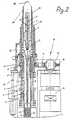
Im einzelnen erkennt man in den Figuren 1 und 2 eine in einemnicht näher bezeichneten Maschinengestell gelagerteWerkzeugspindel 1, die an ihrem vorderen Ende eine Werkzeugaufnahme2 hat. Darin ist ein Bohr- oder Reibwerkzeug 3eingesetzt, welches einen Axialkanal 4 für die Zuführungeines Schmiermittels zu den Werkzeugschneiden aufweist. Anden Axialkanal 4 schließen deshalb Querbohrungen 5 an, dieüber die gesamte Länge des Schneidbereichs des Werkzeugs 3angeordnet sind. Die Zuleitung des Schmiermittels zu demWerkzeug 3 hin erfolgt durch die Werkzeugspindel 1 hindurch,die dazu einen Axialkanal 6 hat, der sich in axialerRichtung weiter bis zum hinteren Ende der Maschine erstreckt.In detail, one can be seen in FIGS. 1 and 2 in oneunspecified machine frameTool spindle 1, which has a tool holder at its
Um den Vorschub des Werkzeugs 3 beim Bearbeitungsvorgang zubesorgen, ist die Werkzeugspindel 1 in ihrer Achsrichtungverschieblich gelagert. Dazu dienen zwei im Maschinengestelldrehbar gelagerte Buchsen 7, die im Innern achsparalleleLängsnuten haben, in denen Kugeln 8 angeordnet sind.Diese Kugeln 8 greifen in achsparallele Längsnuten 9 derWerkzeugspindel 1 ein, so daß die Werkzeugspindel 1 sichmit den drehbar gelagerten Buchsen 7 drehen und unabhängigdavon gegenüber den Buchsen 7 in axialer Richtung verschobenwerden kann. Um möglichst ein radiales Spiel der Werkzeugspindel1 zu vermeiden, sind die Buchsen 7 mit demgrößtmöglichen Abstand zueinander angeordnet. So liegt inder zurückgezogenen Endlage der Werkzeugspindel 1 die Werkzeugaufnahme2 unmittelbar am Austrittsende der vorderenBuchse 7 bezogen auf die Vorschubrichtung. Gleichermaßenliegt das rückwärtige Ende der Werkzeugspindel 1 in dervorgeschobenen Endlage unmittelbar am Eintrittsende derhinteren Buchse 7.To feed the tool 3 during the machining processget, the tool spindle 1 is in its axial directionslidably mounted. Two are used in the machine framerotatably mounted
Die Werkzeugspindel 1 wird durch einen Drehantrieb 15 inRotation versetzt, zu dem ein Zahnkranz 10 gehört, der aufder äußeren Umfangsseite der vorderen Buchse 7 sitzt. Überein Zahnradgetriebe 11 steht dieser Zahnkranz 10 auf derBudhse 7 mit einem Abtriebsrad 12 eines Motors 13 in Verbindung,der zur Werkzeugspindel 1 achsparallel angeordnetist. Bei dem Motor 13 kann es sich um einen Druckluftmotorhandeln, der bei kleiner Baugröße eine relativ hohe Leistunghat.The tool spindle 1 is driven by a
Der Motor 13 wird im Lastfall mit einer vorgegebenen Drehzahlgefahren, damit auch die Werkzeugspindel 1 und somit das Werkzeug 3 auf einer bestimmten Drehzahl gehalten werden.Der Motor 13 kann somit im günstigsten Leistungsbereichbetrieben werden, wobei er selbst nicht nachgesteuertoder -geregelt werden soll. Vielmehr wird lediglich dieDrehzahl des Drehantriebs 15 erfaßt, dazu sitzt an einergeeigneten Stelle im Drehantrieb 15 ein Drehzahlmesser 14.Das drehzahlabhängige Signal des Drehzahlmessers 14 wird ineinen Rechner gegeben, der danach die Vorschubgeschwindigkeitfür die Werkzeugspindel 1 bestimmt. Solange die Drehzahldes Drehantriebs 15 beispielsweise beim Beginn einesBearbeitungsspiels noch nicht bis auf die optimaleLastdrehzahl abgefallen ist, kann mit einem erhöhten Vorschubgefahren werden, der mechanisch von der Drehzahl desDrehantriebs 15 völlig entkoppelt ist. Anstelle einesDruckluftmotors kann für den Motor 13 auch ein Elektromotoreingesetzt werden, der zusätzlich die Möglichkeit bietet,mit einem vorgegebenen Lastmoment betrieben zu werden, dasüber die Stromaufnahme des Elektromotors ermittelt werdenkann.The
Der Rechner steuert einen Vorschubantrieb 25, und zwar derart,daß bei den Leerwegen, über die hinweg das Werkzeug 3nicht im Materialeingriff steht, mit maximaler Vorschubgeschwindigkeitgefahren wird, was sowohl für den Beginn einesArbeitsspiels wie auch für den Rückzug des Werkzeugsgilt. Im übrigen wird der Vorschubantrieb 25 so geregelt,daß optimale Schnittbedingungen unter Berücksichtigung dergünstigsten Lastdrehzahl des Motors 13 eingehalten werden.Hierbei wird zusätzlich noch zwischen einer normalen Bearbeitungund einer Feinbearbeitung unterschieden, wobei im letzteren Falle mit hoher Drehzahl und geringem Vorschubgearbeitet wird.The computer controls a
Wie die Figuren 1 und 3 veranschaulichen, gehört zu demVorschubantrieb 25 eine drehbar gelagerte Gewindespindel17, die in axialer Richtung nicht verschiebbar ist. Die Gewindespindel17 greift in einen hohlen Abschnitt 16 imrückwärtigen Endbereich der Werkzeugspindel 1 ein. Auf derGewindespindel 17 ist eine Mutter 18 derart angeordnet, daßsie in Drehrichtung festliegt, wozu ein Schlitten 20 dient,der auf einer achsparallelen Führung 21 des Maschinengestellsgeführt ist. Diese Führung 21 erstreckt sich übereinen axialen Verschiebebereich der Mutter 18, der sich mitdem gesamten Vorschubweg der Werkzeugspindel 1 deckt. DieWerkzeugspindel 1 ist mit ihrem rückwärtigen Ende des hohlenAbschnitts 16 in der Mutter 18 drehbar gelagert, jedochin Achsrichtung mit der verschieblichen Mutter 18 fest verbunden.Mittels Umlaufkugeln 19, die sowohl in das Gewindeder Gewindespindel 17 als auch in ein Gegengewinde der Mutter18 eingreifen, wird bei Drehung der Gewindespindel 17die axiale Verschiebung der Mutter 18 und damit der Vorschubder Werkzeugspindel 1 bewirkt. Der Rotationsantriebder Gewindespindel 17 erfolgt über ein Riemengetriebe 22durch einen Vorschubmotor 23, bei dem es sich um einenSchrittmotor handeln kann.As illustrated in FIGS. 1 and 3, this includesFeed drive 25 a rotatably mounted threaded
Der Riementrieb 22 treibt ferner ein Meßsystem 24 an, dasvornehmlich aus einem inkrementalen Drehgeber besteht. Überdie von dem Drehgeber gelieferten Signale kann exakt derVorschubweg der Werkzeugspindel 1 ermittelt werden, womiteine absolute Wegmessung möglich ist. Das Meßsystem 24 ist entsprechend mit dem Rechner der Maschine verbunden, um fürdie vorausbestimmbaren Leerwege sowie die Wege der Bearbeitungund der Feinbearbeitung über den Vorschubantrieb 25den Vorschub des Werkzeugs 3 zu steuern und gegebenenfallsin Abhängigkeit von der über den Drehzahlmesser 14 erfaßbarenDrehzahl der Werkzeugspindel 1 nachzuregeln.The
Wie Fig. 1 weiter zeigt weist das Meßsystem 24 zur Erfassungdes Vorschubweges einen Tiefensensor 30 auf, der überein Gestänge 29 mit einem Tastrohr 27 verbunden ist, welchesin einer das Werkzeug 3 in seiner zurückgezogenen Endlageumgebenden Hülse 26 angeordnet ist. Auch das Tastrohr27 umgibt das Werkzeug 3 und hat eine Tastnase 28, die aufdas Material des jeweiligen Werkstücks im Randbereich derzu bearbeitenden Bohrung aufsetzbar ist. Da der Abstandzwischen dem Werkzeug und dem Tastende der Tastnase 28 inderen voll ausgefahrener Position bekannt ist, kann überden Eindrückweg der aufsitzenden Tastnase 28 bei angesetztemBohrgerät über den Tastsensor 30 ein Referenzsignal fürden Werkzeugabstand in der Ausgangslage ermittelt werden.Insbesondere ist damit die Festlegung eines Nullpunktes fürdie Steuerung oder Regelung des Rechners im Zusammenspielmit dem Meßsystem 24 möglich.As further shown in FIG. 1, the measuring
Claims (1)
- Mobile boring unit adapted to be placed on adrilling point of large work pieces for precisionboring work by means of a tool (3) with a tool spindle(1) displaceably arranged in its axial direction in themachine frame with a corresponding tool mount and witha rotation drive (15) as well as a separate feed drive(25) for the axial displacement of the tool spindle(1),
characterised in that
the feed drive (25) is regulated depending upon theaxial feed path by means of a computer in such a waythat the tool spindle (1) is driven by means of therotating drive (15) with pre-specified load speed orpre-specified load torque, that a measurement system(24) for recording the feed path is present which has adepth sensor (30) which is connected with adisplaceable sensory nose (28) which is arrangedaxially parallel to the tool (3) and can be placed onthe work piece for recording a reference signal for thedistance of the tool from the edge area of the bore onthe work piece to be processed, and that the feed drive(25) has a thread spindle (17) arranged in a rotatableway and a nut (18) on the thread spindle displaceablein an axial direction and fixed in a rotation directionand this nut (18) is connected with the tool spindle(1) loosely in the rotation direction and fixed in theaxial direction wherein the thread spindle (17) of thefeed drive (25) is connected with an incrementalrotation indicator (24) as a measurement system forrecording the feed path.
Applications Claiming Priority (3)
| Application Number | Priority Date | Filing Date | Title |
|---|---|---|---|
| DE19934339770DE4339770C2 (en) | 1993-11-23 | 1993-11-23 | Mobile precision drill |
| DE4339770 | 1993-11-23 | ||
| EP95900733AEP0730510B1 (en) | 1993-11-23 | 1994-11-14 | Mobile precision boring tool |
Related Parent Applications (2)
| Application Number | Title | Priority Date | Filing Date |
|---|---|---|---|
| EP95900733ADivisionEP0730510B1 (en) | 1993-11-23 | 1994-11-14 | Mobile precision boring tool |
| EP95900733.7Division | 1995-07-05 |
Publications (3)
| Publication Number | Publication Date |
|---|---|
| EP0838304A2 EP0838304A2 (en) | 1998-04-29 |
| EP0838304A3 EP0838304A3 (en) | 1999-08-18 |
| EP0838304B1true EP0838304B1 (en) | 2003-04-23 |
Family
ID=6503148
Family Applications (2)
| Application Number | Title | Priority Date | Filing Date |
|---|---|---|---|
| EP95900733AExpired - LifetimeEP0730510B1 (en) | 1993-11-23 | 1994-11-14 | Mobile precision boring tool |
| EP97122729AExpired - LifetimeEP0838304B1 (en) | 1993-11-23 | 1994-11-14 | Mobile precision boring tool |
Family Applications Before (1)
| Application Number | Title | Priority Date | Filing Date |
|---|---|---|---|
| EP95900733AExpired - LifetimeEP0730510B1 (en) | 1993-11-23 | 1994-11-14 | Mobile precision boring tool |
Country Status (4)
| Country | Link |
|---|---|
| US (1) | US5755537A (en) |
| EP (2) | EP0730510B1 (en) |
| DE (3) | DE4345409C2 (en) |
| WO (1) | WO1995014550A1 (en) |
Families Citing this family (26)
| Publication number | Priority date | Publication date | Assignee | Title |
|---|---|---|---|---|
| US6105595A (en) | 1997-03-07 | 2000-08-22 | Cooper Technologies Co. | Method, system, and apparatus for automatically preventing or allowing flow of a fluid |
| JP3268495B2 (en)* | 1999-07-09 | 2002-03-25 | ホーコス株式会社 | Spindle device of machine tool |
| GB0021368D0 (en)* | 2000-09-01 | 2000-10-18 | Black & Decker Inc | Rotary hammer |
| US6648562B1 (en)* | 2001-06-08 | 2003-11-18 | Charles D. Calkins | Apparatus for tapping a hole in a pipeline |
| AT502843B1 (en)* | 2004-02-02 | 2009-08-15 | Schoeller Bleckmann Oilfield T | DRILL AND DRILLING METHOD |
| WO2008049459A1 (en)* | 2006-10-24 | 2008-05-02 | Profin Progressive Finish Ag | Tool holder for disk grinding tools |
| DE102006051507A1 (en)* | 2006-10-31 | 2008-05-08 | Kaltenbach & Voigt Gmbh | Control device for driving a dental handpiece operated with a controlled electric motor |
| US8167518B2 (en)* | 2008-04-11 | 2012-05-01 | The Boeing Company | Method and apparatus for a spindle with servo feed control |
| EP3649969A1 (en) | 2008-06-26 | 2020-05-13 | Smart Medical Devices, Inc. | Depth controllable and measurable medical driver devices |
| DE102009050476B4 (en)* | 2009-10-23 | 2015-06-18 | Airbus S.A.S. | drilling |
| KR20130010899A (en) | 2010-03-05 | 2013-01-29 | 세이지 일렉트로크로믹스, 인크. | Lamination of electrochromic device to glass substrates |
| US8894654B2 (en) | 2010-03-31 | 2014-11-25 | Smart Medical Devices, Inc. | Depth controllable and measurable medical driver devices and methods of use |
| FR2961609B1 (en) | 2010-06-21 | 2012-06-01 | Saint Gobain | DEVICE HAVING ELECTRO-CONTROLLABLE OPTICAL AND / OR ENERGY PROPERTIES |
| FR2962818B1 (en) | 2010-07-13 | 2013-03-08 | Saint Gobain | ELECTROCHEMICAL DEVICE HAVING ELECTRO - CONTROLLABLE OPTICAL AND / OR ENERGY TRANSMISSION PROPERTIES. |
| FR2962682B1 (en) | 2010-07-16 | 2015-02-27 | Saint Gobain | ELECTROCHEMICAL WINDOW WITH ELECTRONICALLY CONTROLLED OPTICAL AND / OR ENERGY PROPERTIES |
| FR2969945B1 (en) | 2010-12-30 | 2013-07-19 | Sylvain Guerin | PORTABLE DEVICE FOR MACHINING, ESPECIALLY DRILLING |
| JP5897259B2 (en)* | 2011-02-02 | 2016-03-30 | 東芝機械株式会社 | Machine tool and control method thereof |
| GB2489018B (en)* | 2011-03-16 | 2016-03-30 | Furmanite Internat Ltd | Cutting Apparatus and Drive Assembly |
| EP2834036B1 (en) | 2012-04-05 | 2020-04-29 | Sage Electrochromics, Inc. | Method of thermal laser scribe cutting for electrochromic device production ; corresponding electrochromic panel |
| EP2789862B1 (en)* | 2013-04-10 | 2015-11-04 | ABI Anlagentechnik-Baumaschinen-Industriebedarf Maschinenfabrik und Vertriebsgesellschaft mbH | Oscillation exciter for construction machines |
| CN104907609A (en)* | 2014-03-14 | 2015-09-16 | 力山工业股份有限公司 | A measuring device capable of displaying the machining depth of a drilling machine |
| FR3019768B1 (en)* | 2014-04-14 | 2016-04-01 | Eads Europ Aeronautic Defence | METHOD AND SYSTEM FOR MONITORING THE MACHINING OF A PART BY A PORTABLE AUTOMATIC MACHINING APPARATUS |
| WO2017139674A1 (en) | 2016-02-12 | 2017-08-17 | Smart Medical Devices, Inc. | Driving devices and methods for determining material strength in real-time |
| JP2020508491A (en) | 2017-02-27 | 2020-03-19 | セイジ・エレクトロクロミクス,インコーポレイテッド | Electric device including substrate and transparent conductive layer and process for forming the same |
| JP6967671B2 (en) | 2017-11-06 | 2021-11-17 | セイジ・エレクトロクロミクス,インコーポレイテッド | Articles containing non-luminous variable transmissive devices and coatings |
| CZ2019701A3 (en)* | 2019-11-15 | 2021-01-27 | Deprag Cz A.S. | Robotic machining head |
Family Cites Families (9)
| Publication number | Priority date | Publication date | Assignee | Title |
|---|---|---|---|---|
| US3859001A (en)* | 1973-11-07 | 1975-01-07 | Textron Inc | Quill drive mechanism for machine tools |
| US4076442A (en)* | 1977-03-07 | 1978-02-28 | Cincinnati Milacron, Inc. | Apparatus for controlling coolant flow in accordance to external forces upon a cutting tool |
| US4514123A (en)* | 1981-10-29 | 1985-04-30 | Kearney & Trecker Corporation | Adaptive control system for machine tool or the like |
| US4688970A (en)* | 1985-08-09 | 1987-08-25 | Dresser Industries, Inc. | Power drill and automatic control system therefore |
| KR950007694B1 (en)* | 1988-03-28 | 1995-07-14 | 부라더 고교 가부시기가이샤 | Tool driving unit having arrangement for rotating and reciprocating the tool |
| DE3906254A1 (en)* | 1989-02-28 | 1990-08-30 | Hitachi Seiko Kk | Method and device for processing (machining) a printed circuit board |
| GB2235552B (en)* | 1989-06-23 | 1993-06-16 | Nitto Kohki Co | Controller for boring apparatus |
| JP3138062B2 (en)* | 1992-07-08 | 2001-02-26 | 株式会社アマダ | Drilling machine |
| FR2720308B1 (en)* | 1994-05-31 | 1996-08-09 | Recoules Fils Ets | Pneumatic machining machine. |
- 1993
- 1993-11-23DEDE4345409Apatent/DE4345409C2/ennot_activeExpired - Fee Related
- 1994
- 1994-11-14DEDE59410278Tpatent/DE59410278D1/ennot_activeExpired - Fee Related
- 1994-11-14EPEP95900733Apatent/EP0730510B1/ennot_activeExpired - Lifetime
- 1994-11-14WOPCT/EP1994/003771patent/WO1995014550A1/enactiveIP Right Grant
- 1994-11-14EPEP97122729Apatent/EP0838304B1/ennot_activeExpired - Lifetime
- 1994-11-14DEDE59409112Tpatent/DE59409112D1/ennot_activeExpired - Fee Related
- 1994-11-14USUS08/648,177patent/US5755537A/ennot_activeExpired - Fee Related
Also Published As
| Publication number | Publication date |
|---|---|
| WO1995014550A1 (en) | 1995-06-01 |
| US5755537A (en) | 1998-05-26 |
| EP0730510A1 (en) | 1996-09-11 |
| EP0838304A2 (en) | 1998-04-29 |
| DE4345409C2 (en) | 1998-03-05 |
| DE59410278D1 (en) | 2003-05-28 |
| EP0730510B1 (en) | 2000-01-26 |
| EP0838304A3 (en) | 1999-08-18 |
| DE59409112D1 (en) | 2000-03-02 |
Similar Documents
| Publication | Publication Date | Title |
|---|---|---|
| EP0838304B1 (en) | Mobile precision boring tool | |
| DE68909889T2 (en) | MACHINE TOOL FOR MULTIPLE MACHINING TYPES AND FOR THE COMPLEX MACHINING OF LONG WORKPIECES. | |
| EP1224048B1 (en) | Tool holder | |
| DE602004006174T2 (en) | Tool holder for machine tool, with means for controlling the drilling depth | |
| DE3816737A1 (en) | INTELLIGENT TOOLING SYSTEM | |
| DE2804698A1 (en) | ROTATING DRILL HEAD WITH ADJUSTABLE CUTTING TOOL | |
| DE19915672C2 (en) | Device for processing edges of a plate-shaped workpiece with several cutting tools | |
| EP0970770A1 (en) | Apparatus and method for working drill holes | |
| EP0229909B1 (en) | Deep hole drilling machine | |
| CH679841A5 (en) | ||
| EP3369510A1 (en) | Countersinking tool, tool assembly and method | |
| DE4021090C2 (en) | Machining device with means for changing the radial position of cutting tools | |
| DE202004009215U1 (en) | drilling | |
| DE69219056T2 (en) | Portable drill | |
| EP3081324A1 (en) | Long turning machine with two nc-controlled processing axes and method for machining workpieces on a long turning machine with two nc-controlled processing axes | |
| DE4339770C2 (en) | Mobile precision drill | |
| DE69020870T2 (en) | Multi-spindle automatic lathe. | |
| DE102023109079A1 (en) | Bar loading magazine/bar loader for an automatic lathe and method for operating an automatic lathe with bar loading magazine | |
| DE4013327A1 (en) | MACHINE FOR METAL MACHINING | |
| EP1820601A2 (en) | Sealing for hydrostatic bearing | |
| EP0699493B1 (en) | Chip forming machine tool | |
| DE9318582U1 (en) | Mobile precision drill | |
| DE3522324A1 (en) | Device for machining workpieces | |
| EP2401104B1 (en) | Device for machining workpieces | |
| CH679289A5 (en) | Machining head with rotary tool spindle - has separate motor couple to spindle sleeve for feed movement |
Legal Events
| Date | Code | Title | Description |
|---|---|---|---|
| PUAI | Public reference made under article 153(3) epc to a published international application that has entered the european phase | Free format text:ORIGINAL CODE: 0009012 | |
| AC | Divisional application: reference to earlier application | Ref document number:730510 Country of ref document:EP | |
| AK | Designated contracting states | Kind code of ref document:A2 Designated state(s):DE FR GB IT | |
| PUAL | Search report despatched | Free format text:ORIGINAL CODE: 0009013 | |
| AK | Designated contracting states | Kind code of ref document:A3 Designated state(s):DE FR GB IT | |
| 17P | Request for examination filed | Effective date:20000126 | |
| 17Q | First examination report despatched | Effective date:20010307 | |
| GRAG | Despatch of communication of intention to grant | Free format text:ORIGINAL CODE: EPIDOS AGRA | |
| GRAG | Despatch of communication of intention to grant | Free format text:ORIGINAL CODE: EPIDOS AGRA | |
| GRAH | Despatch of communication of intention to grant a patent | Free format text:ORIGINAL CODE: EPIDOS IGRA | |
| GRAH | Despatch of communication of intention to grant a patent | Free format text:ORIGINAL CODE: EPIDOS IGRA | |
| GRAA | (expected) grant | Free format text:ORIGINAL CODE: 0009210 | |
| AC | Divisional application: reference to earlier application | Ref document number:0730510 Country of ref document:EP Kind code of ref document:P | |
| AK | Designated contracting states | Designated state(s):DE FR GB IT | |
| PG25 | Lapsed in a contracting state [announced via postgrant information from national office to epo] | Ref country code:IT Free format text:LAPSE BECAUSE OF FAILURE TO SUBMIT A TRANSLATION OF THE DESCRIPTION OR TO PAY THE FEE WITHIN THE PRE;WARNING: LAPSES OF ITALIAN PATENTS WITH EFFECTIVE DATE BEFORE 2007 MAY HAVE OCCURRED AT ANY TIME BEFORE 2007. THE CORRECT EFFECTIVE DATE MAY BE DIFFERENT FROM THE ONE RECORDED.SCRIBED TIME-LIMIT Effective date:20030423 | |
| REG | Reference to a national code | Ref country code:GB Ref legal event code:FG4D Free format text:NOT ENGLISH | |
| RAP2 | Party data changed (patent owner data changed or rights of a patent transferred) | Owner name:JOHANNES LUEBBERING AG | |
| REF | Corresponds to: | Ref document number:59410278 Country of ref document:DE Date of ref document:20030528 Kind code of ref document:P | |
| GBT | Gb: translation of ep patent filed (gb section 77(6)(a)/1977) | ||
| ET | Fr: translation filed | ||
| PLBE | No opposition filed within time limit | Free format text:ORIGINAL CODE: 0009261 | |
| STAA | Information on the status of an ep patent application or granted ep patent | Free format text:STATUS: NO OPPOSITION FILED WITHIN TIME LIMIT | |
| 26N | No opposition filed | Effective date:20040126 | |
| PGFP | Annual fee paid to national office [announced via postgrant information from national office to epo] | Ref country code:DE Payment date:20081110 Year of fee payment:15 | |
| PGFP | Annual fee paid to national office [announced via postgrant information from national office to epo] | Ref country code:FR Payment date:20081113 Year of fee payment:15 | |
| PGFP | Annual fee paid to national office [announced via postgrant information from national office to epo] | Ref country code:GB Payment date:20081008 Year of fee payment:15 | |
| GBPC | Gb: european patent ceased through non-payment of renewal fee | Effective date:20091114 | |
| REG | Reference to a national code | Ref country code:FR Ref legal event code:ST Effective date:20100730 | |
| PG25 | Lapsed in a contracting state [announced via postgrant information from national office to epo] | Ref country code:FR Free format text:LAPSE BECAUSE OF NON-PAYMENT OF DUE FEES Effective date:20091130 | |
| PG25 | Lapsed in a contracting state [announced via postgrant information from national office to epo] | Ref country code:DE Free format text:LAPSE BECAUSE OF NON-PAYMENT OF DUE FEES Effective date:20100601 | |
| PG25 | Lapsed in a contracting state [announced via postgrant information from national office to epo] | Ref country code:GB Free format text:LAPSE BECAUSE OF NON-PAYMENT OF DUE FEES Effective date:20091114 |