EP0838237B1 - Breathing apparatus and facepiece therefor - Google Patents
Breathing apparatus and facepiece thereforDownload PDFInfo
- Publication number
- EP0838237B1 EP0838237B1EP97307228AEP97307228AEP0838237B1EP 0838237 B1EP0838237 B1EP 0838237B1EP 97307228 AEP97307228 AEP 97307228AEP 97307228 AEP97307228 AEP 97307228AEP 0838237 B1EP0838237 B1EP 0838237B1
- Authority
- EP
- European Patent Office
- Prior art keywords
- diaphragm
- facepiece
- wearer
- valve
- gas
- Prior art date
- Legal status (The legal status is an assumption and is not a legal conclusion. Google has not performed a legal analysis and makes no representation as to the accuracy of the status listed.)
- Expired - Lifetime
Links
- 230000029058respiratory gaseous exchangeEffects0.000titleclaimsdescription10
- 238000007789sealingMethods0.000claimsdescription13
- 230000005540biological transmissionEffects0.000claimsdescription9
- 239000000356contaminantSubstances0.000claims1
- 239000007789gasSubstances0.000description6
- 210000003128headAnatomy0.000description4
- 239000012528membraneSubstances0.000description4
- XLYOFNOQVPJJNP-UHFFFAOYSA-NwaterSubstancesOXLYOFNOQVPJJNP-UHFFFAOYSA-N0.000description4
- 239000000463materialSubstances0.000description3
- 239000004033plasticSubstances0.000description3
- 229920003023plasticPolymers0.000description3
- 230000000241respiratory effectEffects0.000description3
- CURLTUGMZLYLDI-UHFFFAOYSA-NCarbon dioxideChemical compoundO=C=OCURLTUGMZLYLDI-UHFFFAOYSA-N0.000description2
- 238000005202decontaminationMethods0.000description2
- 230000003588decontaminative effectEffects0.000description2
- 238000000034methodMethods0.000description2
- 230000001681protective effectEffects0.000description2
- 239000000779smokeSubstances0.000description2
- 208000035473Communicable diseaseDiseases0.000description1
- 230000002411adverseEffects0.000description1
- 229910002092carbon dioxideInorganic materials0.000description1
- 239000001569carbon dioxideSubstances0.000description1
- 238000010276constructionMethods0.000description1
- 238000011109contaminationMethods0.000description1
- 230000008878couplingEffects0.000description1
- 238000010168coupling processMethods0.000description1
- 238000005859coupling reactionMethods0.000description1
- 230000001419dependent effectEffects0.000description1
- 230000000881depressing effectEffects0.000description1
- 230000003670easy-to-cleanEffects0.000description1
- 238000007654immersionMethods0.000description1
- 239000002184metalSubstances0.000description1
- 230000001473noxious effectEffects0.000description1
- 230000001105regulatory effectEffects0.000description1
- 239000012858resilient materialSubstances0.000description1
- 239000000126substanceSubstances0.000description1
Images


Classifications
- A—HUMAN NECESSITIES
- A62—LIFE-SAVING; FIRE-FIGHTING
- A62B—DEVICES, APPARATUS OR METHODS FOR LIFE-SAVING
- A62B9/00—Component parts for respiratory or breathing apparatus
- A62B9/02—Valves
Definitions
- This inventionrelates to breathing apparatus whereby breathable gas is supplied automatically to the wearer in accordance with his respiratory requirements. More particularly, it relates to apparatus of the "Positive Pressure" type, wherein a pressure which is a predetermined level above the pressure of the ambient atmosphere is maintained within the facepiece so as to prevent inward leakage of air, noxious gases or smoke, etc., from the surrounding atmosphere into the interior of the facepiece.
- Breathing apparatus of the positive pressure typeis well known, and is commonly used by firefighters for entering smoke-filled buildings or while dealing with chemical spills. For these purposes, it is normal to use apparatus of the self-contained type where a supply of air or other breathable gas is carried by the wearer in one or more high pressure cylinders.
- a typical apparatuscomprises a cylinder containing compressed air at high pressure, typically 200 to 300 bar, which is carried on the wearer's back by means of a backplate or frame, to which is attached an adjustable webbing harness.
- the cylinderis fitted with a stop valve, to which is connected a first stage pressure regulating valve which reduces the air supply pressure to a substantially constant value of, say, 7 bar.
- the airis supplied by this first stage regulator, via a flexible hose, to a second stage regulator, commonly known as a demand valve, which is attached to a full facepiece of rubber or a similar resilient material.
- the facepieceis conventionally, held to the wearer's face in a lead-tight manner by means of an adjustable head harness.
- the facepiecewhich has a transparent visor, is fitted with a non-return valve through which the wearer's exhaled breath is exhausted to atmosphere.
- This valveis spring loaded so as to open only when pressure within the facepiece exceeds the predetermined level above that of the surrounding atmosphere, this difference normally being set at about 4 millibar.
- the demand valveresponds to pressure changes within the facepiece and is spring loaded or biased so as to open and admit air from the first regulator when pressure within the facepiece falls, due to inhalation by the wearer or outward leakage, to a level below, say, 3 millibar above the ambient outside pressure.
- pressure within the facepieceis maintained at a level of between 3 and 4 millibar above the ambient outside pressure.
- connection between the demand valve and the facepieceis commonly by means of a bayonet or similar coupling which can be rapidly assembled or disassembled by the wearer.
- the facepieceis also conventionally fitted with a speech transmission diaphragm, comprising a taut membrane of thin metal or high strength plastics material, supported in a rigid housing in the front of the facepiece and protected by a grille.
- a speech transmission diaphragmcomprising a taut membrane of thin metal or high strength plastics material, supported in a rigid housing in the front of the facepiece and protected by a grille.
- An audible alarmusually a whistle or bell, indicates when cylinder pressure has fallen to or below a predetermined level.
- the facepieceincorporating the speech transmission diaphragm, spring loaded exhalation valve and connection for the demand valve, is a complex assembly of many parts and is thus costly to produce. Its cost is often so high as to inhibit the provision of personal facepieces to each of the individuals in a firefighting team, for example. This situation, in which facepieces must be "shared" by two or more team members, may give rise to objections relating to communicable diseases and certainly necessitates very thorough decontamination of the facepiece after every use.
- the demand valvewhich is in the respiratory circuit and thus also susceptible to contamination, is not easy to clean effectively, due to the need to prevent the ingress into the passages in the valve of water which may subsequently freeze, adversely affecting its operation.
- Disconnection of the demand valve from the facepieceexposes the outlet of the valve to the ingress of dirt or water which may later affect operation of the valve, or may be inhaled by the wearer.
- the demand valvebeing mounted externally to the facepiece, is exposed to extremes of temperature and forms a significant protrusion which is susceptible to catching on obstructions with the subsequent risk of dislodging the facepiece.
- the assemblymay thus be permanently, or semi-permanently attached to the facepiece, greatly increasing the integrity of the apparatus and reducing the overall size, weight and cost due to the reduced number of component parts.
- the preferred embodiments of the inventionalso place the working parts of the breathing valves within the facepiece where they are protected from extremes of temperature, and also provide a means of preventing ingress of water into the demand valve, so that the complete facepiece and valve assembly may be readily washed and decontaminated by immersion.
- a facepieceis provided according to claim 1.
- a speech transmission diaphragm assembly 1comprises a taut membrane 2 held in a rigid circular housing 3.
- This diaphragm assembly 1is rigidly fixed to a lever 4, pivoted at 5 and biased by a spring 6 such that the diaphragm is urged towards a deformable resilient seal 7, clamped at its periphery to a housing 8.
- the seal 7is so configured that it can, after making sealing contact with the diaphragm assembly 1, allow further “inward” movement of the diaphragm (towards the wearer) beyond the initial "closed” position seen in Figure 1.
- the force of the spring 6is such as to urge the diaphragm to close the opening defined by the seal 7, and is sufficient to deform or deflect the seal 7 further, beyond this initial "closed" position in the absence of a pressure difference across the diaphragm.
- a lever 9is pivoted at 10 and is biased by a light spring 11 so as to close off a small pilot jet 12.
- the relative sizes of the pilot jet 12 and metering orifice 15are such that the pilot jet 12 can exhaust the pilot chamber 13 faster than the metering orifice 15 can replenish it.
- the supply of air to the facepieceis controlled by a two-stage main valve composed of the resilient disc 16, whose opening and closing is in turn controlled by the opening and closing of a pilot arrangement, composed of the pilot chamber 13 and jet 12.
- the pilot arrangementis in turn controlled by the movement of the lever 9, which is moved by the diaphragm 1 when diaphragm 1 moves inwards in response to a reduction in pressure within the facepiece.
- the biasing spring 6is sufficiently strong to move the diaphragm, in the absence of any pressure difference across the diaphragm, from a first position in which initial contact is made with seal 7 but with seal 7 unmoved, into a third position in which seal is moved toward the wearer and the diaphragm 1 contacts the screw 9a of lever 9. The diaphragm 1 and seal 7 remain in sealing contact throughout this movement.
- a cover 21which is shown in dotted lines, protects the assembly from damage and from radiant heat, and has suitably positioned openings (not shown) to allow for the unhindered passage of the exhaled air to atmosphere. These openings also provide a path for sounds transmitted through the diaphragm 1, allowing the clear transmission of speech.
- a lifting and latching meansis provided to move the diaphragm 1 away from the resilient seal 7, and to hold it in this open position.
- a lifting arrangementis seen at 30, where the diaphragm 1 is provided with a finger tab 30 projecting downwardly from its lower end.
- latching means 30a and 30bare provided to retain the diaphragm in its lifted position.
- detent 30aengages with pivoting latch 30b when the diaphragm is lifted by the wearer.
- Leftwards (as seen in the Figure) pressure at the lower part 30c of pivoting latch 30bcauses the latch 30b rotate clockwise and to disengage from the detent 30b, and spring 7 then returns the diaphragm 1 to its initial position in contact with seal 6, to continue the normal operating sequence.
- lifting the diaphragm 1opens a port of substantial area, directly in front of the wearer's nose and mouth.
- the latchmay be arranged in other configurations than that shown, provided the latch can operate to hold the diaphragm 1 in the open position. While the latch may be engaged and released, or "tripped", by a single action, such as by pressing a projecting button, release arrangements requiring more determined manipulation are foreseen.
- the latching meansis preferably designed so that a double action is required by the wearer to engage the latch, such as by simultaneously depressing two buttons on opposite sides of the valve assembly.
- a manually operated bypass, or override, valve(not shown) may be provided, whereby a controlled flow of air may be admitted to the facepiece at will.
- a stop valvemay be provided between the pressurised air supply tank and the facepiece, since it will be appreciated that if the wearer removes the facepiece without latching the diaphragm 1 open, the diaphragm 1 will be moved by the spring 6 to open the pilot valve 12 and allow a free flow of air.
- the diaphragm 1is mounted on a resiliently biassed telescopic support comprising a bearing post 40 attached to the housing of the facepiece and a sleeve 41 attached to the outer face of the diaphragm assembly.
- a spring 42surrounds the post 40 and urges the sleeve 41 and diaphragm 1 and the seal 7 towards the wearer.
- Other mounting arrangementsare foreseen for the diaphragm, in addition to the pivotal movement shown in Figure 1 and the rectilinear movement illustrated in Figure 2.
- the seal 7is permanently attached to the periphery of the diaphragm 1, and has a sealing lip which contacts the body 8 of the facepiece.
- the flexible nature of the seal 7allows the diaphragm to move towards the wearer after making initial sealing contact with the facepiece, so that lever 9 may be operated to open the supply valve 16 in a manner similar to that described with reference to the embodiment shown in Figure 1.
- the diaphragm 1is formed with a threaded embossment 1a, and an adjusting screw S extends through the embossment 1a to contact the end of a lever 9 which operates the demand valve (not shown) in a manner similar to that described in relation to Figure 1.
- FIGS 3A and 3Bshown in greater detail the demand valve 3.
- lever 9is urged by spring 11 ( Figure 1) to close the pilot jet 12.
- Pilot chamber 13is pressurised by air entering from the metering orifice 15, and resilient sealing disc 16 is urged by this pressure to close the exit ports 18 in the flange 17.
- Outlet 20is closed by a resilient flap 19.
- pilot jet 12When lever 9 is moved by diaphragm 1, pilot jet 12 is opened and air in the pilot chamber 13 escapes through jet 12 faster than it enters via metering orifice 15, thus depressurising the pilot chamber 13. High pressure in the supply tube 14 then deforms the disc 16, and air can pass from supply tube 14 to outlet ports 18 and thence to outlet 20, where the pressure raises resilient flap 19 and allows air to exit to the interior of the facepiece.
- the diaphragmcan be arranged so as to open the demand valve when the diaphragm 1 and seal 7 have moved inwardly from their position of initial sealing contact, and can close the demand valve as the diaphragm 1 and seal 7 move outwardly together before the diaphragm loses contact with the seal 7.
- the facepiecemay be a simple assembly of a clear plastics visor 22, attached around its periphery to a resilient seal 23 and secured to the wearer's face by means of an adjustable head harness (also not shown).
- An opening in the visor 22accommodates the integrated valve assembly previously described, which may be secured in the opening by means of screws or clips.
- the facepieceis provided with an inner half-mask 24.
- Air entering the facepiece from the valve outlet 20is directed into the upper area of the visor and passes through non-return flaps 25 into the half-mask 24, to be inhaled by the wearer. Exhaled air passes directly to atmosphere around the diaphragm 1, which is situated in front of the wearer's mouth for optimum speech transmission. This circuitous passage of the air through the facepiece prevents misting of the visor, ventilates the upper area of the wearer's face and minimises the amount of carbon dioxide inhaled by the wearer.
- the facepiececovers the entire face of the wearer.
- the combined speech transmission diaphragm, exhalation valve and demand valve control arrangement described abovemay however also be embodied in a facepiece which covers only the wearer's nose and mouth. In such cases it is foreseen that separate eye protection may be provided. This arrangement may be advantageous for example in breathing apparatus intended for aircrew.
- the combined exhaust valve and demand valvemay form part of a hood or helmet which extends to cover the entire head of a wearer.
- a hood formed from flexible materialis foreseen, sealed round the wearer's neck, and inflated by the gas supply from a demand valve actuated by a diaphragm arrangement as previously described.
- the demand valveis incorporated in a helmet, the helmet may be fully pressurised, or may have a sealing membrane engaging the wearers' head to enclose the nose and mouth and optionally the eyes. The volume within the sealing membrane will be supplied with pressurised air by the demand valve.
- the demand valvemay be incorporated into a hood or helmet forming part of a protective garment for the upper body, or of a complete body suit.
- the demand valvemay supply pressurised air at a predetermined temperature to the wearer for respiration, and the same or a further demand valve assembly may supply air to the interior of the garment or suit to cool the wearer.
- the supply of breathable gasmay be from self-contained cylinders carried by the wearer, or may be from a supply reservoir remote from the wearer and connected to the demand valve via a hose.
- the components of the demand valvemay be moulded from plastics materials, to reduce weight and cost.
Landscapes
- Health & Medical Sciences (AREA)
- Pulmonology (AREA)
- General Health & Medical Sciences (AREA)
- Business, Economics & Management (AREA)
- Emergency Management (AREA)
- Respiratory Apparatuses And Protective Means (AREA)
Description
- This invention relates to breathing apparatuswhereby breathable gas is supplied automatically to thewearer in accordance with his respiratory requirements.More particularly, it relates to apparatus of the"Positive Pressure" type, wherein a pressure which is apredetermined level above the pressure of the ambientatmosphere is maintained within the facepiece so as toprevent inward leakage of air, noxious gases or smoke,etc., from the surrounding atmosphere into the interiorof the facepiece.
- Breathing apparatus of the positive pressure typeis well known, and is commonly used by firefighters forentering smoke-filled buildings or while dealing withchemical spills. For these purposes, it is normal to useapparatus of the self-contained type where a supply ofair or other breathable gas is carried by the wearer inone or more high pressure cylinders.
- A typical apparatus comprises a cylinder containingcompressed air at high pressure, typically 200 to 300bar, which is carried on the wearer's back by means ofa backplate or frame, to which is attached an adjustablewebbing harness. The cylinder is fitted with a stopvalve, to which is connected a first stage pressureregulating valve which reduces the air supply pressureto a substantially constant value of, say, 7 bar. Theair is supplied by this first stage regulator, via a flexible hose, to a second stage regulator, commonlyknown as a demand valve, which is attached to a fullfacepiece of rubber or a similar resilient material. Thefacepiece is conventionally, held to the wearer's facein a lead-tight manner by means of an adjustable headharness.
- The facepiece, which has a transparent visor, isfitted with a non-return valve through which the wearer'sexhaled breath is exhausted to atmosphere. This valveis spring loaded so as to open only when pressure withinthe facepiece exceeds the predetermined level above thatof the surrounding atmosphere, this difference normallybeing set at about 4 millibar.
- The demand valve responds to pressure changes withinthe facepiece and is spring loaded or biased so as toopen and admit air from the first regulator when pressurewithin the facepiece falls, due to inhalation by thewearer or outward leakage, to a level below, say, 3millibar above the ambient outside pressure. By thismeans, pressure within the facepiece is maintained at alevel of between 3 and 4 millibar above the ambientoutside pressure.
- In order to allow a fully attired wearer to breatheatmospheric air in areas where it is safe to do so, andthus conserve his limited air supply, and also tofacilitate decontamination of the facepiece after use,the connection between the demand valve and the facepiece is commonly by means of a bayonet or similar couplingwhich can be rapidly assembled or disassembled by thewearer.
- The facepiece is also conventionally fitted with aspeech transmission diaphragm, comprising a taut membraneof thin metal or high strength plastics material,supported in a rigid housing in the front of thefacepiece and protected by a grille. The cleartransmission of speech is of critical importance in manysituations in which breathing apparatus is worn,particularly in firefighting.
- It is also conventional to provide a gauge toindicate the air pressure in the cylinder, in order toallow the wearer to monitor his air supply. An audiblealarm, usually a whistle or bell, indicates when cylinderpressure has fallen to or below a predetermined level.
- The typical apparatus described above has a numberof limitations and disadvantages, which the presentinvention seeks to overcome.
- The facepiece, incorporating the speech transmissiondiaphragm, spring loaded exhalation valve and connectionfor the demand valve, is a complex assembly of many partsand is thus costly to produce. Its cost is often so highas to inhibit the provision of personal facepieces toeach of the individuals in a firefighting team, forexample. This situation, in which facepieces must be"shared" by two or more team members, may give rise to objections relating to communicable diseases andcertainly necessitates very thorough decontamination ofthe facepiece after every use. The demand valve, whichis in the respiratory circuit and thus also susceptibleto contamination, is not easy to clean effectively, dueto the need to prevent the ingress into the passages inthe valve of water which may subsequently freeze,adversely affecting its operation.
- The necessity, for firefighters in particular, tobe completely attired in their protective clothing andequipment prior to entering an area where respiratoryprotection becomes necessary, requires that the demandvalve be disconnectable from the facepiece to allow thewearer to breathe atmospheric air whilst conserving hiscompressed air supply. This procedure, in turn,necessitates that an additional device be incorporatedinto the demand valve to override its positive pressureoperation so as to prevent free escape of air and torestore demand operation when the valve is reconnectedto the facepiece or when the wearer first inhales fromthe valve.
- Disconnection of the demand valve from the facepieceexposes the outlet of the valve to the ingress of dirtor water which may later affect operation of the valve,or may be inhaled by the wearer. The demand valve, beingmounted externally to the facepiece, is exposed toextremes of temperature and forms a significant protrusion which is susceptible to catching onobstructions with the subsequent risk of dislodging thefacepiece.
- It is the object of the present invention toovercome the disadvantages described by providing asingle integrated assembly incorporating the demandvalve, exhalation valve and speech transmission diaphragmwith a means of allowing the wearer to conserve hissupply of breathable gas and breathe from the atmosphereat will without either removing the demand valve assemblyfrom the facepiece, or removing the facepiece from hisface. The assembly may thus be permanently, or semi-permanentlyattached to the facepiece, greatly increasingthe integrity of the apparatus and reducing the overallsize, weight and cost due to the reduced number ofcomponent parts.
- It is a further object of the invention to providea fixed and minimal differential between the openingpressure of the exhalation valve and the opening pressureof the demand valve, and to further reduce the overallwork of breathing for the wearer by providing anexhalation valve of considerably greater area than couldnormally be accommodated in a conventional apparatus.The preferred embodiments of the invention also place theworking parts of the breathing valves within thefacepiece where they are protected from extremes oftemperature, and also provide a means of preventing ingress of water into the demand valve, so that thecomplete facepiece and valve assembly may be readilywashed and decontaminated by immersion.
- According to a first aspect of the invention, a facepieceis provided according to
claim 1. - Particular embodiments are defined by the dependent claims.
- Embodiments of the invention will now be describedin detail, with reference to the accompanying drawings,in which:
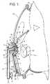
- Figure 1 shows a sectional side elevation of apreferred embodiment of the invention;
- Figure 2 is an enlarged fragmentary view, showingan alternative method of supporting the diaphragm andseal;
- Figure 3A is an enlarged sectional view of thedemand valve in its closed position; and
- Figure 3B is a view similar to Figure 3A, showingthe demand valve open to admit air to the facepiece.
- Referring now to Figure 1, a speech
transmissiondiaphragm assembly 1 comprises ataut membrane 2 held ina rigidcircular housing 3. Thisdiaphragm assembly 1is rigidly fixed to alever 4, pivoted at 5 and biasedby aspring 6 such that the diaphragm is urged towardsa deformableresilient seal 7, clamped at its peripheryto ahousing 8. Theseal 7 is so configured that it can,after making sealing contact with thediaphragm assembly 1, allow further "inward" movement of the diaphragm(towards the wearer) beyond the initial "closed" positionseen in Figure 1. The force of thespring 6 is such asto urge the diaphragm to close the opening defined by theseal 7, and is sufficient to deform or deflect theseal 7 further, beyond this initial "closed" position in theabsence of a pressure difference across the diaphragm. - A
lever 9 is pivoted at 10 and is biased by alightspring 11 so as to close off asmall pilot jet 12. Whenthepilot jet 12 is closed by thelever 9, the pressurewithin apilot chamber 13, resulting from air enteringthechamber 13 from anair inlet 14 through ameteringorifice 15 in the centre of aresilient disc 16, clampsthedisc 16 against a face of aflange 17. The relativesizes of thepilot jet 12 andmetering orifice 15 aresuch that thepilot jet 12 can exhaust thepilot chamber 13 faster than themetering orifice 15 can replenish it.Any escape of air through thepilot jet 12 causes areduction in pressure within thechamber 13, allowing theresilient disc 16 to bow away from theflange 17 underthe influence of air pressure at theinlet 14, exposinga series ofopenings 18 in the flange through which airmay pass from theinlet 14 to anoutlet 20 and thenceinto the interior of the facepiece. The free end oflever 9 is provided with an adjustingscrew 9a to varythe position of the diaphragm assembly at which initialcontact is made with thelever 9. Clearly, embodimentsare foreseeable wherein an adjustable abutment isprovided on the diaphragm, and a fixed abutment onlever 9. When thescrew 9a is correctly adjusted, thediaphragm is just out of contact with the lever when thepressure within the facepiece exceeds atmospheric pressure by the required pressure difference. "Inward"movement of thediaphragm 1, beyond that initial contactposition will cause the diaphragm to come into contactwith thescrew 9a at the end oflever 9, and pivot thelever away from thepilot jet 12, allowing air to exitthrough thejet 12 from thepilot chamber 13. - A resilient
non-return flap 19, which protects thevalve outlet 20 from the ingress of water, deflects toallow air to pass freely from the valve into thefacepiece. - It will be understood from the foregoing that thesupply of air to the facepiece is controlled by a two-stagemain valve composed of the
resilient disc 16, whoseopening and closing is in turn controlled by the openingand closing of a pilot arrangement, composed of thepilotchamber 13 andjet 12. The pilot arrangement is in turncontrolled by the movement of thelever 9, which is movedby thediaphragm 1 whendiaphragm 1 moves inwards inresponse to a reduction in pressure within the facepiece. - It is emphasised that in operation, forces act onthe diaphragm due to the resilient nature of the
seal 7,the biasingspring 6 of thediaphragm assembly 1, and theforce exerted by pressure differences on the diaphragm.The biasingspring 6 is sufficiently strong to move thediaphragm, in the absence of any pressure differenceacross the diaphragm, from a first position in whichinitial contact is made withseal 7 but withseal 7 unmoved, into a third position in which seal is movedtoward the wearer and thediaphragm 1 contacts thescrew 9a oflever 9. Thediaphragm 1 andseal 7 remain insealing contact throughout this movement. - When the facepiece is sealed to the wearer's face,initially no pressure difference exists between theinterior of the diaphragm and the outside atmosphere.The
diaphragm 1 is urged inward by the biasingspring 6.Seal 7 is deformed asdiaphragm 1 moves inward under theaction ofspring 6.Diaphragm 1 contacts and moveslever 9 to open thepilot valve 12, and air is admitted intothe facepiece until the pressure within the facepiecerises to a superatmospheric level sufficient to urge thediaphragm 1 to move outwards against the force ofspring 6. As thediaphragm 1 moves outwardly under theincreasing pressure within the facepiece,lever 9 isurged byspring 11 to follow the movement of thediaphragm untillever 9 closes thepilot jet 12. A stateof equilibrium will then exist if pressure within thefacepiece is maintained at this level. - When the wearer inhales, pressure within thefacepiece falls below the equilibrium level. The
diaphragm 1 then moves inwards under the action ofspring 6, deflecting theresilient seal 7 and opening thepilotvalve 12 again to admit air to the facepiece. Wheninhalation ceases, pressure within the facepiece willrise again, urging thediaphragm 1 outwards, restoring the equilibrium pressure level and allowing thepilotvalve 12 to close. The diaphragm remains tightly closedon theseal 7 throughout the inhalation phase. - When the wearer exhales, pressure within thefacepiece will rise above the equilibrium level, and thispressure difference across
diaphragm 1 urges thediaphragm outwards. After a small outward movement ofboth thediaphragm 1 and theseal 1, theseal 7 reachesthe limit of its movement.Diaphragm 1 thereaftercontinues to move away from theresilient seal 7 toexpose a gap around the periphery of thediaphragm 1,through which the excess air is vented to atmosphere.Acover 21, which is shown in dotted lines, protects theassembly from damage and from radiant heat, and hassuitably positioned openings (not shown) to allow for theunhindered passage of the exhaled air to atmosphere.These openings also provide a path for sounds transmittedthrough thediaphragm 1, allowing the clear transmissionof speech. - In a preferred development of the invention, inorder to allow the wearer to breathe atmospheric airwithout removal of the facepiece, a lifting and latchingmeans is provided to move the
diaphragm 1 away from theresilient seal 7, and to hold it in this open position.In Figure 1, such a lifting arrangement is seen at 30,where thediaphragm 1 is provided with afinger tab 30projecting downwardly from its lower end. By placing a finger to the right (as seen in the Figure) of thetab 30 and moving it to the left, the wearer may move thediaphragm away fromseal 7 to allow free ingress andegress of air into the facepiece. It is emphasised thatthelever 9 is unmoved by lifting the diaphragm in thisway, and thus the demand valve remains closed, conservingthe air supply. - In the most preferred embodiment, latching means 30aand 30b are provided to retain the diaphragm in itslifted position. In the embodiment of Figure 1,
detent 30a engages with pivotinglatch 30b when the diaphragmis lifted by the wearer. Leftwards (as seen in theFigure) pressure at the lower part 30c of pivotinglatch 30b causes thelatch 30b rotate clockwise and todisengage from thedetent 30b, andspring 7 then returnsthediaphragm 1 to its initial position in contact withseal 6, to continue the normal operating sequence. - In the illustrated embodiment, lifting the
diaphragm 1 opens a port of substantial area, directly in front ofthe wearer's nose and mouth. The latch may be arrangedin other configurations than that shown, provided thelatch can operate to hold thediaphragm 1 in the openposition. While the latch may be engaged and released,or "tripped", by a single action, such as by pressing aprojecting button, release arrangements requiring moredetermined manipulation are foreseen. In order toprevent inadvertent or accidental opening of the diaphragm, the latching means is preferably designed sothat a double action is required by the wearer to engagethe latch, such as by simultaneously depressing twobuttons on opposite sides of the valve assembly. Whenthediaphragm 1 is in the open position, it isnecessarily out of contact withlever 9, and thus thepilot valve 12 remains closed, conserving the air supply.The wearer may then remove the facepiece without loss ofpressurised air through the demand valve. - A manually operated bypass, or override, valve (notshown) may be provided, whereby a controlled flow of airmay be admitted to the facepiece at will. Additionallyor alternatively, a stop valve may be provided betweenthe pressurised air supply tank and the facepiece, sinceit will be appreciated that if the wearer removes thefacepiece without latching the
diaphragm 1 open, thediaphragm 1 will be moved by thespring 6 to open thepilot valve 12 and allow a free flow of air. - In the embodiment shown in Figure 2, the
diaphragm 1 is mounted on a resiliently biassed telescopic supportcomprising a bearingpost 40 attached to the housing ofthe facepiece and asleeve 41 attached to the outer faceof the diaphragm assembly. Aspring 42 surrounds thepost 40 and urges thesleeve 41 anddiaphragm 1 and theseal 7 towards the wearer. Other mounting arrangementsare foreseen for the diaphragm, in addition to thepivotal movement shown in Figure 1 and the rectilinear movement illustrated in Figure 2. - In the embodiment seen in Figure 2, the
seal 7 ispermanently attached to the periphery of thediaphragm 1, and has a sealing lip which contacts thebody 8 of thefacepiece. The flexible nature of theseal 7 allows thediaphragm to move towards the wearer after making initialsealing contact with the facepiece, so thatlever 9 maybe operated to open thesupply valve 16 in a mannersimilar to that described with reference to theembodiment shown in Figure 1. - An alternative arrangement for adjusting theposition at which the diaphragm opens the demand valveis shown. In this embodiment, the
diaphragm 1 is formedwith a threaded embossment 1a, and an adjusting screw Sextends through the embossment 1a to contact the end ofalever 9 which operates the demand valve (not shown) ina manner similar to that described in relation to Figure1. - Figures 3A and 3B shown in greater detail the
demandvalve 3. In Figure 3A,lever 9 is urged by spring 11(Figure 1) to close thepilot jet 12.Pilot chamber 13is pressurised by air entering from themetering orifice 15, andresilient sealing disc 16 is urged by thispressure to close theexit ports 18 in theflange 17.Outlet 20 is closed by aresilient flap 19. - When
lever 9 is moved bydiaphragm 1,pilot jet 12is opened and air in thepilot chamber 13 escapes throughjet 12 faster than it enters viametering orifice 15,thus depressurising thepilot chamber 13. High pressurein thesupply tube 14 then deforms thedisc 16, and aircan pass fromsupply tube 14 tooutlet ports 18 andthence tooutlet 20, where the pressure raisesresilientflap 19 and allows air to exit to the interior of thefacepiece. - Alternative construction for the demand valve areforeseen, provided that the diaphragm can be arranged soas to open the demand valve when the
diaphragm 1 andseal 7 have moved inwardly from their position of initialsealing contact, and can close the demand valve as thediaphragm 1 andseal 7 move outwardly together before thediaphragm loses contact with theseal 7. - The facepiece may be a simple assembly of a
clearplastics visor 22, attached around its periphery to aresilient seal 23 and secured to the wearer's face bymeans of an adjustable head harness (also not shown).An opening in thevisor 22 accommodates the integratedvalve assembly previously described, which may be securedin the opening by means of screws or clips. In thepreferred embodiment of the invention shown, thefacepiece is provided with an inner half-mask 24. - Air entering the facepiece from the
valve outlet 20is directed into the upper area of the visor and passesthroughnon-return flaps 25 into the half-mask 24, to beinhaled by the wearer. Exhaled air passes directly to atmosphere around thediaphragm 1, which is situated infront of the wearer's mouth for optimum speechtransmission. This circuitous passage of the air throughthe facepiece prevents misting of the visor, ventilatesthe upper area of the wearer's face and minimises theamount of carbon dioxide inhaled by the wearer. - In the embodiments described, the facepiece coversthe entire face of the wearer. The combined speechtransmission diaphragm, exhalation valve and demand valvecontrol arrangement described above may however also beembodied in a facepiece which covers only the wearer'snose and mouth. In such cases it is foreseen thatseparate eye protection may be provided. Thisarrangement may be advantageous for example in breathingapparatus intended for aircrew.
- It is further envisaged that the combined exhaustvalve and demand valve may form part of a hood or helmetwhich extends to cover the entire head of a wearer. Ahood formed from flexible material is foreseen, sealedround the wearer's neck, and inflated by the gas supplyfrom a demand valve actuated by a diaphragm arrangementas previously described. Where the demand valve isincorporated in a helmet, the helmet may be fullypressurised, or may have a sealing membrane engaging thewearers' head to enclose the nose and mouth andoptionally the eyes. The volume within the sealingmembrane will be supplied with pressurised air by the demand valve.
- In yet a further alternative, the demand valve maybe incorporated into a hood or helmet forming part of aprotective garment for the upper body, or of a completebody suit. The demand valve may supply pressurised airat a predetermined temperature to the wearer forrespiration, and the same or a further demand valveassembly may supply air to the interior of the garmentor suit to cool the wearer.
- In any of the above-described embodiments, thesupply of breathable gas may be from self-containedcylinders carried by the wearer, or may be from a supplyreservoir remote from the wearer and connected to thedemand valve via a hose.
- It is envisaged that the components of the demandvalve may be moulded from plastics materials, to reduceweight and cost.
Claims (21)
- A facepiece (8, 21, 22, 23) for a breathingapparatus for supplying a breatheable gas to a wearer andfrom which exhaled gas is exhaustable, the facepieceincluding:characterised bya supply valve (16, 17, 18) for deliveringbreatheable gas to the interior of the facepiece; and
an exhaust opening closeable by an exhaust valve (1,2, 3) for allowing the egress of exhaled gas from theinterior of the facepiece, wherein the exhaust valvecomprises an inwardly biased diaphragm (2) movablerelative to the exhaust opening and having a firstposition in which the diaphragm closes said exhaustopening and is in sealing engagement therewith, a secondposition in which said diaphragm is displaced towards theinterior of the facepiece relative to the first positionwith the diaphragm still in sealing engagement with theexhaust opening, and a third position in which thediaphragm is displaced outwardly of said facepiecerelative to said first position and wherein said exhaustopening is open for allowing egress of exhaled gas;
biasing means (6) operative to bias the diaphragmtowards said second position; and
operating means (9, 9a) engageable by said diaphragm when said diaphragm is in said second position foropening said supply valve. - A facepiece according to claim 1, including asealing element (7) positioned between the diaphragm andthe periphery of the exhaust opening to seal thediaphragm to the exhaust opening when the diaphragm isin its first position and while the diaphragm movesbetween its first and second positions.
- A facepiece according to claim 2, wherein thesealing element (7) is mounted on the facepiece (8) tosurround the exhaust opening.
- A facepiece according to claim 2, wherein thesealing element (7) is mounted on the diaphragm.
- A facepiece according to any preceding claim,wherein the diaphragm is pivotally mounted (4, 5) to thefacepiece.
- A facepiece according to any of claims 1 to 5,wherein the diaphragm is mounted for rectilinear movement(40, 41) relative to the exhaust opening.
- A facepiece according to any preceding claim,wherein adjustment means (9a, S) are provided to adjustthe distance between the first and second positions ofthe diaphragm.
- A facepiece according to any preceding claim,wherein the operating means which opens the supply valve(16, 17, 18) is an operating lever (9).
- A facepiece according to claim 8, wherein adjustmentmeans (9a, S) is provided between the operating lever (9)and the diaphragm to adjust the point on the travel ofthe diaphragm at which contact with the operating leveris made.
- A facepiece according to claim 9, wherein theadjustment means comprises a fixed abutment on thediaphragm and a movable abutment (9a) mounted on thelever (9).
- A facepiece according to claim 9, wherein theadjustment means comprises a fixed abutment on the lever(9) and a movable abutment (S) mounted on the diaphragm.
- A facepiece according to any preceding claim, further including means (30) operable to move thediaphragm to its third position.
- A facepiece according to any preceding claim,further including releaseable means (30a, 30b, 31)operable to retain the diaphragm in its third position.
- A facepiece according to claim 13, wherein thereleaseable means comprises a movable latch element (31)engageable with a detent (30a).
- A facepiece according to claim 14, wherein the latchelement (31) is mounted on the facepiece (21) and thedetent (30a) is mounted on the diaphragm.
- A facepiece according to any preceding claim,wherein the diaphragm includes a speech transmissiondiaphragm.
- A facepiece according to any preceding claim,wherein the interior of the facepiece is divided (24)into upper and lower compartments, the upper compartmentbeing adapted to cover the wearer's eyes and having atransparent sight window, and the lower compartment beingadapted to cover the wearer's mouth and nasal openings and having the diaphragm mounted thereon, the supplyvalve being operable to deliver breatheable gas to theupper compartment, and a non-return valve (25) beingprovided to allow gas to flow from the upper compartmentto the lower compartment.
- A facepiece according to any of claims 1 to 16,wherein the facepiece covers the wearer's nose and mouthonly.
- A facepiece according to any preceding claim,wherein the supply valve further includes a movable cover(19) to close an outlet opening (20) of the supply valvefor preventing the ingress of contaminants, the cover(19) being movable away from the outlet opening (20) bypressure of the breatheable gas delivered by the supplyvalve.
- A facepiece according to claim 19 wherein themovable cover is a resilient flap (19) extending acrossthe outlet opening (20).
- A breathing apparatus to supply breatheable gas toa wearer, comprising a source of breatheable gas atsuperambient pressure and a facepiece according to any preceding claim.
Applications Claiming Priority (2)
| Application Number | Priority Date | Filing Date | Title |
|---|---|---|---|
| GB9619459 | 1996-09-18 | ||
| GBGB9619459.2AGB9619459D0 (en) | 1996-09-18 | 1996-09-18 | Breathing apparatus |
Publications (3)
| Publication Number | Publication Date |
|---|---|
| EP0838237A2 EP0838237A2 (en) | 1998-04-29 |
| EP0838237A3 EP0838237A3 (en) | 1999-04-07 |
| EP0838237B1true EP0838237B1 (en) | 2003-02-26 |
Family
ID=10800101
Family Applications (1)
| Application Number | Title | Priority Date | Filing Date |
|---|---|---|---|
| EP97307228AExpired - LifetimeEP0838237B1 (en) | 1996-09-18 | 1997-09-17 | Breathing apparatus and facepiece therefor |
Country Status (4)
| Country | Link |
|---|---|
| US (1) | US6016802A (en) |
| EP (1) | EP0838237B1 (en) |
| DE (1) | DE69719280D1 (en) |
| GB (1) | GB9619459D0 (en) |
Families Citing this family (43)
| Publication number | Priority date | Publication date | Assignee | Title |
|---|---|---|---|---|
| AU759612B2 (en)* | 1998-10-09 | 2003-04-17 | Fisher & Paykel Limited | A connector |
| US6206003B1 (en)* | 1998-12-11 | 2001-03-27 | John M. Burch | Mask with integral valve |
| US6279172B1 (en) | 2000-02-02 | 2001-08-28 | Gentex Corporation | Custom fitting assembly for helmet |
| BR0209549B1 (en)* | 2001-05-11 | 2012-01-24 | respirator face piece. | |
| GB2378745B (en)* | 2001-08-15 | 2005-07-13 | Internat Safety Instr Inc | Demand valve for breathing apparatus |
| US6758212B2 (en)* | 2002-06-24 | 2004-07-06 | Brookdale International Systems, Inc. | Personal emergency breathing system |
| US20040194829A1 (en)* | 2002-09-19 | 2004-10-07 | Zaiser Lenoir E. | Differential pressure valve employing near-balanced pressure |
| GB0222497D0 (en)* | 2002-09-27 | 2002-11-06 | Secr Defence | Respirator |
| US6736137B1 (en) | 2003-02-28 | 2004-05-18 | Tmr-A, Llc | Protective hooded respirator with oral-nasal cup breathing interface |
| GB2402458B (en)* | 2003-06-06 | 2006-04-19 | Internat Safety Instr Inc | Demand valves for breathing apparatus |
| US7100628B1 (en)* | 2003-11-18 | 2006-09-05 | Creare Inc. | Electromechanically-assisted regulator control assembly |
| PT1582231E (en)* | 2004-04-02 | 2012-09-27 | Intersurgical Ag | Improvements relating to respiratory masks |
| TWM270826U (en)* | 2004-09-10 | 2005-07-21 | Mesure Technology Co Ltd | Mask |
| SE531310C2 (en)* | 2005-04-12 | 2009-02-17 | Interspiro Ab | Respirator |
| AU2008231059B2 (en) | 2007-03-23 | 2011-03-17 | 3M Innovative Properties Company | Respirator flow control apparatus and method |
| EP2205324B1 (en)* | 2007-10-05 | 2018-06-20 | 3M Innovative Properties Company | Respirator flow control apparatus and method |
| EP2361656B1 (en)* | 2010-02-26 | 2016-06-08 | Dräger Safety AG & Co. KGaA | Respirator mask |
| AU2011292804B2 (en) | 2010-08-19 | 2014-11-13 | Koninklijke Philips Electronics N.V. | Manually actuated talk valve for a respiratory device |
| GB2490507C (en)* | 2011-05-03 | 2020-08-12 | Intersurgical Ag | Respiratory mask |
| US8844533B2 (en)* | 2011-06-22 | 2014-09-30 | Breathe Technologies, Inc. | Ventilation mask with integrated piloted exhalation valve |
| US9410717B2 (en)* | 2011-10-12 | 2016-08-09 | Ford Global Technologies, Llc | Powered diaphragm air extractor and control system |
| US20140014110A1 (en)* | 2012-07-16 | 2014-01-16 | Phillip M. Adams | Remotely controlled positive airway-pressure apparatus and method |
| US9950202B2 (en) | 2013-02-01 | 2018-04-24 | 3M Innovative Properties Company | Respirator negative pressure fit check devices and methods |
| US9517367B2 (en) | 2013-02-01 | 2016-12-13 | 3M Innovative Properties Company | Respiratory mask having a clean air inlet chamber |
| US11052268B2 (en) | 2013-02-01 | 2021-07-06 | 3M Innovative Properties Company | Respirator negative pressure fit check devices and methods |
| GB2511363B (en)* | 2013-03-01 | 2019-03-27 | Draeger Safety Uk Ltd | Lung Demand Valve |
| US9517318B2 (en)* | 2013-06-28 | 2016-12-13 | L'Air Liquide, Société Anonyme pour l'Etude et l'Exploitation des Procédés Georges Claude | Method of delivering medical gases via a nasal cannula assembly with flow control passage communicating with a deformable reservoir |
| US9492626B2 (en)* | 2013-06-28 | 2016-11-15 | L'Air Liquide, Société Anonyme pour l'Etude et l'Exploitation des Procédés Georges Claude | Breathing assistance assemblies suitable for long term no therapy |
| US9486600B2 (en)* | 2013-06-28 | 2016-11-08 | L'Air Liquide, Société Anonyme pour l'Etude et l'Exploitation des Procédés Georges Claude | Nasal cannula assembly with inhalation valves communicating with a deformable reservoir |
| US9566407B2 (en)* | 2013-06-28 | 2017-02-14 | L'Air Liquide, Société Anonyme pour l'Etude et l'Exploitation des Procédés Georges Claude | Nasal cannula assembly with flow control passage communicating with a deformable reservoir |
| US9522248B2 (en)* | 2013-06-28 | 2016-12-20 | L'Air Liquide, Société Anonyme pour l'Etude et l'Exploitation des Procédés Georges Claude | Breathing assistance apparatus for delivery of nitric oxide to a patient by means of a nasal cannula assembly with flow control passage |
| US9522247B2 (en)* | 2013-06-28 | 2016-12-20 | L'Air Liquide, Société Anonyme pour l'Etude et l'Exploitation des Procédés Georges Claude | Method of treating a patient having pulmonary hypertension by long term NO therapy |
| GB2521644B (en) | 2013-12-24 | 2020-03-11 | Intersurgical Ag | Improvements relating to respiratory masks |
| KR102420496B1 (en) | 2016-03-28 | 2022-07-13 | 쓰리엠 이노베이티브 프로퍼티즈 캄파니 | Multi-chamber respiratory seal device and method |
| USD827810S1 (en) | 2016-03-28 | 2018-09-04 | 3M Innovative Properties Company | Hardhat suspension adapter for half facepiece respirators |
| CN113769289B (en) | 2016-03-28 | 2023-02-17 | 3M创新有限公司 | Respirator tightness checking and sealing device |
| USD816209S1 (en) | 2016-03-28 | 2018-04-24 | 3M Innovative Properties Company | Respirator inlet port connection seal |
| EP3436161A4 (en) | 2016-03-28 | 2020-01-22 | 3M Innovative Properties Company | SUSPENSION FASTENER FOR HEADGEAR |
| USD842982S1 (en) | 2016-03-28 | 2019-03-12 | 3M Innovative Properties Company | Hardhat suspension adapter for half facepiece respirators |
| CN106617315A (en)* | 2016-11-11 | 2017-05-10 | 周成龙 | Electronic cigarette |
| GB201808993D0 (en)* | 2018-06-01 | 2018-07-18 | Avon Polymer Prod Ltd | Speech diaphram module for a respirator mask |
| WO2023050016A1 (en) | 2021-10-01 | 2023-04-06 | Markdom International Inc. | Injection molded vehicle compartment pressure relief valve |
| US12128740B2 (en) | 2021-12-10 | 2024-10-29 | Markdom International Inc. | Vehicle accessory apparatus with incomplete assembly indicator |
Family Cites Families (14)
| Publication number | Priority date | Publication date | Assignee | Title |
|---|---|---|---|---|
| US3109425A (en)* | 1960-03-04 | 1963-11-05 | Electric Storage Battery Co | Respirator speaking diaphragm and exhalation valve unit |
| DE2908528C2 (en)* | 1979-03-05 | 1984-04-05 | Drägerwerk AG, 2400 Lübeck | Lung-controlled breathing apparatus with positive pressure inside the mask |
| DE3245717C1 (en)* | 1982-12-10 | 1984-06-07 | Drägerwerk AG, 2400 Lübeck | Lung-controlled valve for overpressure operation in the mask interior |
| SE446656B (en)* | 1985-01-08 | 1986-09-29 | Astra Meditec Ab | VALVED CLUTCH DEVICE |
| US4762145A (en)* | 1987-05-13 | 1988-08-09 | G.S.D. Sports Equipment S.R.L. | Underwater pressure relief valve |
| US4834085A (en)* | 1987-12-10 | 1989-05-30 | Webster Ii John W | Person-to-person resuscitation device |
| US5042473A (en)* | 1990-02-15 | 1991-08-27 | Pro-Tech Respirators, Inc. | Demand valve for a respirator |
| NO921853D0 (en)* | 1992-05-11 | 1992-05-11 | Iver Hansen | air cleaning |
| DE4237294C1 (en)* | 1992-11-05 | 1993-11-25 | Draegerwerk Ag | Breathing mask with positive pressure inside the mask |
| GB9301959D0 (en)* | 1993-02-01 | 1993-03-17 | Sabre Safety Ltd | A valve for use in breathing apparatus |
| SE502129C2 (en)* | 1993-11-05 | 1995-08-28 | Poseidon Ind Ab | Valve device and respirator including such valve device |
| US5584288A (en)* | 1994-02-03 | 1996-12-17 | Baldwin; Gene R. | Multi-stage mouth-to-mouth resuscitator valve |
| DE4418788A1 (en)* | 1994-05-24 | 1995-11-30 | Interspiro Gmbh | Breathing connection with regulator |
| DE9409320U1 (en)* | 1994-06-08 | 1995-07-06 | Berlin, Florence, Genf | Respirator and microphone holder for use therein |
- 1996
- 1996-09-18GBGBGB9619459.2Apatent/GB9619459D0/enactivePending
- 1997
- 1997-09-17EPEP97307228Apatent/EP0838237B1/ennot_activeExpired - Lifetime
- 1997-09-17USUS08/932,039patent/US6016802A/ennot_activeExpired - Lifetime
- 1997-09-17DEDE69719280Tpatent/DE69719280D1/ennot_activeExpired - Lifetime
Also Published As
| Publication number | Publication date |
|---|---|
| GB9619459D0 (en) | 1996-10-30 |
| DE69719280D1 (en) | 2003-04-03 |
| EP0838237A2 (en) | 1998-04-29 |
| EP0838237A3 (en) | 1999-04-07 |
| US6016802A (en) | 2000-01-25 |
Similar Documents
| Publication | Publication Date | Title |
|---|---|---|
| EP0838237B1 (en) | Breathing apparatus and facepiece therefor | |
| EP1341582B1 (en) | Breathing apparatus | |
| US6371110B1 (en) | Automatic release apparatus and methods for respirator devices | |
| US8215303B2 (en) | Breathing apparatus | |
| US5690095A (en) | Emergency escape breathing apparatus | |
| EP0363530A1 (en) | Respirator | |
| WO1997046281A1 (en) | Breathing apparatus | |
| WO2003095031A1 (en) | Respirator assembly | |
| GB2575233A (en) | A breathing apparatus | |
| US4361145A (en) | Respirator mask | |
| US5156145A (en) | Self-contained breathing system apparatus with automatic back-up | |
| EP0632736B1 (en) | Breathing apparatus for respiratory protection | |
| GB2209123A (en) | Breathing apparatus | |
| US20030116156A1 (en) | Breathing apparatus | |
| AU705233B2 (en) | Face mask | |
| WO1990002078A1 (en) | Simplified respirator | |
| EP0956100B1 (en) | Breathing equipment | |
| KR200498645Y1 (en) | Multifunctional auxiliary breathing device | |
| FR2793147A1 (en) | Protective garment for operating in polluted atmosphere comprises supple airtight suit with air feed, mask and valve to evacuate used air | |
| HK1056333B (en) | Breathing apparatus | |
| HU184043B (en) | Oxygen escape device particularly for using in mine areas | |
| GB2365357A (en) | Hooded breathing apparatus |
Legal Events
| Date | Code | Title | Description |
|---|---|---|---|
| PUAI | Public reference made under article 153(3) epc to a published international application that has entered the european phase | Free format text:ORIGINAL CODE: 0009012 | |
| AK | Designated contracting states | Kind code of ref document:A2 Designated state(s):DE FR GB IT SE | |
| PUAL | Search report despatched | Free format text:ORIGINAL CODE: 0009013 | |
| AK | Designated contracting states | Kind code of ref document:A3 Designated state(s):AT BE CH DE DK ES FI FR GB GR IE IT LI LU MC NL PT SE | |
| 17P | Request for examination filed | Effective date:19991006 | |
| AKX | Designation fees paid | Free format text:DE FR GB IT SE | |
| 17Q | First examination report despatched | Effective date:20011003 | |
| GRAH | Despatch of communication of intention to grant a patent | Free format text:ORIGINAL CODE: EPIDOS IGRA | |
| GRAH | Despatch of communication of intention to grant a patent | Free format text:ORIGINAL CODE: EPIDOS IGRA | |
| GRAA | (expected) grant | Free format text:ORIGINAL CODE: 0009210 | |
| AK | Designated contracting states | Designated state(s):DE FR GB IT SE | |
| PG25 | Lapsed in a contracting state [announced via postgrant information from national office to epo] | Ref country code:IT Free format text:LAPSE BECAUSE OF FAILURE TO SUBMIT A TRANSLATION OF THE DESCRIPTION OR TO PAY THE FEE WITHIN THE PRE;WARNING: LAPSES OF ITALIAN PATENTS WITH EFFECTIVE DATE BEFORE 2007 MAY HAVE OCCURRED AT ANY TIME BEFORE 2007. THE CORRECT EFFECTIVE DATE MAY BE DIFFERENT FROM THE ONE RECORDED.SCRIBED TIME-LIMIT Effective date:20030226 Ref country code:FR Free format text:LAPSE BECAUSE OF NON-PAYMENT OF DUE FEES Effective date:20030226 | |
| REG | Reference to a national code | Ref country code:GB Ref legal event code:FG4D | |
| REF | Corresponds to: | Ref document number:69719280 Country of ref document:DE Date of ref document:20030403 Kind code of ref document:P | |
| PG25 | Lapsed in a contracting state [announced via postgrant information from national office to epo] | Ref country code:SE Free format text:LAPSE BECAUSE OF FAILURE TO SUBMIT A TRANSLATION OF THE DESCRIPTION OR TO PAY THE FEE WITHIN THE PRESCRIBED TIME-LIMIT Effective date:20030526 | |
| PG25 | Lapsed in a contracting state [announced via postgrant information from national office to epo] | Ref country code:DE Free format text:LAPSE BECAUSE OF FAILURE TO SUBMIT A TRANSLATION OF THE DESCRIPTION OR TO PAY THE FEE WITHIN THE PRESCRIBED TIME-LIMIT Effective date:20030527 | |
| PLBE | No opposition filed within time limit | Free format text:ORIGINAL CODE: 0009261 | |
| STAA | Information on the status of an ep patent application or granted ep patent | Free format text:STATUS: NO OPPOSITION FILED WITHIN TIME LIMIT | |
| EN | Fr: translation not filed | ||
| 26N | No opposition filed | Effective date:20031127 | |
| PGFP | Annual fee paid to national office [announced via postgrant information from national office to epo] | Ref country code:GB Payment date:20120918 Year of fee payment:16 | |
| GBPC | Gb: european patent ceased through non-payment of renewal fee | Effective date:20130917 | |
| PG25 | Lapsed in a contracting state [announced via postgrant information from national office to epo] | Ref country code:GB Free format text:LAPSE BECAUSE OF NON-PAYMENT OF DUE FEES Effective date:20130917 |