EP0837529B1 - Cover of terminal fitting - Google Patents
Cover of terminal fittingDownload PDFInfo
- Publication number
- EP0837529B1 EP0837529B1EP97305388AEP97305388AEP0837529B1EP 0837529 B1EP0837529 B1EP 0837529B1EP 97305388 AEP97305388 AEP 97305388AEP 97305388 AEP97305388 AEP 97305388AEP 0837529 B1EP0837529 B1EP 0837529B1
- Authority
- EP
- European Patent Office
- Prior art keywords
- cover
- terminal fitting
- receiving member
- fitting
- inserting member
- Prior art date
- Legal status (The legal status is an assumption and is not a legal conclusion. Google has not performed a legal analysis and makes no representation as to the accuracy of the status listed.)
- Expired - Lifetime
Links
- 238000003780insertionMethods0.000claimsdescription24
- 230000037431insertionEffects0.000claimsdescription24
- 239000003381stabilizerSubstances0.000claimsdescription17
- 239000000463materialSubstances0.000claimsdescription5
- 239000002184metalSubstances0.000claimsdescription4
- 229910052751metalInorganic materials0.000claimsdescription4
- 238000005452bendingMethods0.000description9
- 238000004519manufacturing processMethods0.000description4
- 239000010935stainless steelSubstances0.000description4
- 229910001220stainless steelInorganic materials0.000description4
- 238000000034methodMethods0.000description3
- 238000005476solderingMethods0.000description3
- 229910000881Cu alloyInorganic materials0.000description2
- 238000005520cutting processMethods0.000description2
- 238000005728strengtheningMethods0.000description2
- 238000004891communicationMethods0.000description1
- 230000000694effectsEffects0.000description1
- 238000009413insulationMethods0.000description1
- 238000003825pressingMethods0.000description1
- 229920003002synthetic resinPolymers0.000description1
- 239000000057synthetic resinSubstances0.000description1
- 230000003313weakening effectEffects0.000description1
Images


Classifications
- H—ELECTRICITY
- H01—ELECTRIC ELEMENTS
- H01R—ELECTRICALLY-CONDUCTIVE CONNECTIONS; STRUCTURAL ASSOCIATIONS OF A PLURALITY OF MUTUALLY-INSULATED ELECTRICAL CONNECTING ELEMENTS; COUPLING DEVICES; CURRENT COLLECTORS
- H01R13/00—Details of coupling devices of the kinds covered by groups H01R12/70 or H01R24/00 - H01R33/00
- H01R13/02—Contact members
- H01R13/15—Pins, blades or sockets having separate spring member for producing or increasing contact pressure
- H01R13/18—Pins, blades or sockets having separate spring member for producing or increasing contact pressure with the spring member surrounding the socket
Definitions
- the present inventionrelates to a cover for attachment to the exterior of an electrical terminal fitting.
- Miniaturized terminal fittings using thin metal sheet as materialare employed in, for example, automobile communication signal lines where electrical wires with a relatively low amperage rating are used.
- a lanceis deemed necessary in the terminal fitting for preventing removal after attachment in a connector housing; however, the thin metal sheet cannot give a sufficient stopping effect even if the side faces of the terminal fittings are cut away to form the lance.
- the conventional terminal fitting of this typehas a cover formed from stainless steel sheet, or the like, into an angular tubular shape.
- a lance 'c'is formed by cutting away a side face of the cover 'a', the cover 'a' being capable of being attached to the exterior of a terminal fitting 'b'.
- the stainless steel coveris stronger than the copper alloy usually used for the terminal fitting itself.
- the conventional cover 'a'is formed by bending stainless steel sheet, and since the configuration is such that one end merely makes contact with a plate face of the other end, there are disadvantages, like the junction 'd' opening easily, etc., thereby weakening the shape supporting strength thereof.
- the overhanging member of the lance 'c'is in a free state, there is a problem in that the stopping force thereof is weak.
- DE-A-3629740discloses a tubular cover for an electrical terminal which corresponds to the pre-characterizing portion of claim 1.
- the present inventionhas been developed after taking the above problems into consideration, and aims to present a terminal fitting cover with a superior shape supporting strength, and which can be produced at a low cost.
- a tubular metal cover for an electrical terminalthe cover being of sheet material, and having abutting sides, an insertion member of one side being engaged in a receiving member of the other side as the cover is formed, characterized in that the cover is rectangular in section and folded, the insertion member of said one side comprises a projection in the plane of the sheet material, the projection being engageable with the receiving member inwardly of the edge of the other side, the other side thereby defining an upstanding protrusion, the protrusion being adapted to act as a stabilizer during insertion of said cover in a connector housing, and wherein said upstanding protrusion is stepped inwardly of the cover so as to extend in a plane parallel to the plane of said other side, and wherein the insertion member is deformable to latch with the receiving member.
- Such a coverensures that the abutting edges are restrained without the need for soldering of the junction. Further support may be provided when the cover and terminal assembly are inserted into a connector housing, and in this way an undercut of the connector housing can be avoided.
- the receiving membercan also be deformable to latch with the insertion member thus forming a strong self-supporting cover.
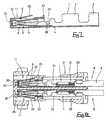
- a female terminal fitting 1is formed from copper alloy sheet which has superior conductivity. After the sheet is stamped out, bending is carried out in sequence, and as a result, the form shown in Figure 1 is achieved. From the posterior end, the following are provided in a unified manner: an insulation barrel 2 to which the end 9 of an electric wire 8 (see Figure 8) is attached; a wire barrel 3 to which the end of a core wire 10 is attached; a connecting member 4; and an insertion member 5 into which a protruding member of a corresponding male terminal fitting (not shown) is inserted.
- the insertion member 5is partitioned into an upper and a lower portion, and forms an overall angular tubular shape that tapers off in the anterior direction. Its upper and lower faces have a pair of resilient contacts 6 that are formed so as to protrude inwards (see Figure 7). Since the protruding member of the corresponding male terminal fitting is gripped between the resilient contacts 6 when it is inserted, electrical connectivity is established between the male and female terminal fittings.
- the cover 11is arranged to be attachable to the exterior of the insertion member 5 of the female terminal fitting 1.
- This cover 11is of stainless steel sheet and its overall shape is angular tubular, formed by bending from a stamping ( Figure 5).
- This stampinghas, when seen from the top of the drawing downwards, the following parts in sequence: an upper face plate 12, a left side plate 13 (seen from a front face), a base face plate 14 and a right side plate 15. Bending lines are shown by broken lines in the drawing.
- the right side plate 15has a greater width than the corresponding left side plate 13, the end portions of this right side plate 15 forming a stabilizer 17. Consequently, when bent, the end of the upper face plate 12 makes contact with the base end of the stabilizer 17.
- the upper face plate 12has an L-shaped slit 19 formed from its edge, thereby forming a lance 20 that faces posteriorly.
- the anterior and posterior edges of the ends of the upper face plate 12have a pair of inserting members 22 protruding therefrom.
- the anterior and posterior edges of the ends of the stabilizer 17have a corresponding pair of fitting grooves or cut-outs 23 formed by cutting away. These fitting grooves 23 are cut-in to a position adjacent the base portion of the stabilizer 17, and are formed to be slightly narrower than the inserting members 23, mouths 24 widening in a tapering shape so as to provide a guiding function.
- the production process of the cover 11is as follows. First, as described above, the flat plate is stamped out ( Figure 5) and by means of several bending operations, the angular tubular shape is achieved. During this bending operation, the anterior end of the lance 20 is bent diagonally upwards, and the stabilizer 17 is formed in a diagonally stepped manner inwards with respect to the plate face of the right side plate 15. Furthermore, during the assembly, the inserting member 22 at the posterior end of the upper face plate 12 is inserted into the corresponding fitting groove 23 of the stabilizer 17 via the mouth 24. As this is taking place, the anterior end portions of all the plate faces 12-15 are bent inwards at right angles, and a through hole 25 is formed for inserting the contacting protruding member of the male terminal fitting. Finally, the cover 11 is separated from a carrier 26.
- the cover 11, formed as described above,is inserted so as to cover the exterior of the insertion member 5 from the anterior end of the female fitting 1.
- the posterior edge of the upper face plate 12 of the cover 11is prevented from being pushed in further by its making contact with a protruding member 27 formed so as to rise upwards from the posterior end of the upper face of the insertion member 5.
- stopping members 28, formed on the posterior ends of the left and right side plates 13 and 15 of the cover 11,are bent inwards into a groove 29 formed in the connecting member 4 of the female terminal fitting 1, thereby fixing the cover 11 with the female terminal fitting 1. In this manner, resilient contacts 6 are protected.
- the connector housing 31is made of synthetic resin, and its interior has cavities 32 provided at an upper and lower level.
- the cavities 32have stopping protrusions 33 for stopping the lance 20, an anterior face wall 35 of the cavity 32 having a through hole 36 which allows the insertion of the protruding contacting member of a male terminal fitting.
- the female terminal fitting 1has the cover 11 fitted and fixed thereto, and the electric wire 8 is fixed to the barrels 2 and 3.
- the female terminal fitting 1is inserted from the posterior end into the cavity 32 of the connector housing 31, and during this insertion, the stabilizer 17 provided in the cover 11 is pushed so as to become aligned with a guiding groove 38 provided in the cavity 32, and is thereby inserted smoothly.
- the lance 20is stopped by the stopping protrusion 33 of the cavity 32, thereby retaining it in an unremovable condition.
- the through hole 25 of the cover 11is located immediately behind the through hole 36 at the anterior face of the cavity 32.
- the inserting members 22are pushed into the fitting grooves 23 and thus the shape supporting strength is high, so that it is not damaged too easily. Further, when it is attached to the female terminal fitting 1, the lance 20 provided therein can also perform a satisfactory stopping function, and the protection of the resilient contact 6 is also carried out with certainty. Moreover, since the operation of insertion of the inserting member 22 into the fitting groove 23 is carried out simultaneously with the bending operation thereof into an angular tabular shape, it becomes unnecessary to set up a subsequent process, and production can be carried out without incurring an increase in cost.
- the insertion operation of the female cavity 32can be carried out smoothly. Since the terminal fitting 1 into the stabilizer 17 is formed in a stepped manner and is retracted inwards with respect to the right side plate 15 of the cover 11, the anterior end of the inserting member 22 inserted into the fitting groove 23 can be positioned in a retracted location with respect to the plate face of the right side plate 15 ( Figure 4). For this reason, it becomes unnecessary to make design changes such as providing concave cut-away grooves on the inner wall of the cavity 32.
- a cover 41 of this embodimenthas, instead of the fitting grooves 23 of the first embodiment, window holes 42 formed so as to correspond with inserting members 22, the inserting members 22 fitting tightly therein and the window holes 42 being formed on a plate face of a base portion of a stabilizer 17A. Further, an angular portion of the anterior end of the inserting member 22 is rounded so as to facilitate smooth insertion into the window hole 42. Since the configuration of the other parts is the same as in the first embodiment, the same numbers are accorded to parts having the same configuration as in the first embodiment, and an explanation thereof omitted.
- the inserting members 22 at the anterior and posterior ends of the upper face plate 12are inserted into the corresponding window holes 42 located on the base end portion of the stabilizer 17A.
- the cover 41 shown in Figure 9is thereby formed.
- the stabilizer 17Ais formed to be stepped in its interior side, the anterior end of the inserting member 22 inserted into the window hole 42 can be housed in a location that is retracted with respect to the plate face of the right side plate 15, thereby being advantageous in a likewise manner by making it unnecessary to provide concave cut-away grooves on the inner wall of the cavity 32.
- This embodimentfurther strengthens the fixing strength of the pressed-in portion constituted by the fitting groove 23 and the inserting member 22 of the first embodiment. Since the configuration of the other parts is the same as in the first embodiment, the same numbers are accorded to parts having the same configuration as in the first embodiment, and an explanation thereof omitted.
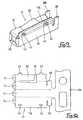
- a cover 51 of the third embodimentis assembled in the same manner as the first embodiment, and furthermore, an inserting member 22 is pressed in so as to ensure that the fitting groove 23 and the inserting member 22 fit into each other, thereby strengthening the attachment of the fitting groove 23 and the inserting member 22.
- the pressing inis carried out as follows. First, the cover 11 which has been assembled up to the point described in the first embodiment is inserted into a jig 52 from its posterior end, the jig 52 being open only from above. The cover 11 is thus housed tightly and supported therein, thereby controlling the movement of the cover 11 in an outward direction. That is, as shown in Figure 12, the base face of the jig 52 and the left and right side faces are fitted tightly with a base plate 14, a left side plate 13 and a right side plate 15 of the cover 11.
- the upper edge portion of the right side face of the jig 52forms an overhanging portion 53 that protrudes so as to fit tightly with the stepped portion retreated inwards from the boundary between the right side plate 15 and the stabilizer 17.
- the upper face of the overhanging member 53makes tight contact with the lower face of the inserting member 22 and receives and supports the inserting member 22 from below.
- the interior of the cover 11has a core 55 inserted therein from the posterior side, the core 55 making tight contact with the interior faces.
- the core 55prevents a change of shape of the cove 11 in the inward direction.
- the upper face of the inserting member 22is pressed in by means of a punch 56.
- the center of the upper face of the inserting member 22becomes concave, the anterior and posterior external edges of the inserting member 22 getting pressed towards the inner side edges of the fitting groove 23, this pressing-in occurring only to the extent of the amount of change of shape of a concave portion 57.
- both the inner side of the fitting groove 23 and the outer side of the inserting member 22become concave and undergo a change in shape so as to fit tightly into each other.
- the core 55is taken out from the posterior end, and the cover 51 is taken out from the jig 52 from the posterior end.
- the fourth embodimentfurther strengthens the attachment strength of the pressed-in portion of the window hole 42 and the inserting member 22 in the cover 41 of the second embodiment. Since the configuration of the other parts is the same as in the second embodiment, the same numbers are accorded to parts having the same configuration as in the first embodiment, and an explanation thereof omitted.
- a cover 61 of this embodimentis assembled in the same manner as the first embodiment, and furthermore, an inserting member 22 is pushed in so as to make a window hole 42 and the inserting member 22 fit into each other, thereby strengthening the attachment of the window hole 42 and the inserting member 22.
- the cover 41 ofthe second embodimentis housed and supported in a jig (not shown), the upper face of the jig being open.
- a portion of the inserting member 22 protruding from a stabilizer 17Ais pressed in by means of a punch (not shown) in a direction indicated by the arrow P in Figure 14 to spread the edges thereof.
- a central portion of the outer side of the inserting member 22thus gets pressed in so as to form a concave portion 62 thereon.
- the cover 61 of the present embodimentalso has a window hole 42 and the inserting member 22 fitted together by means of a pressing-in operation. Accordingly, compared to the cover 41 of the second embodiment, the shape supporting strength is further increased.
Landscapes
- Connector Housings Or Holding Contact Members (AREA)
- Details Of Connecting Devices For Male And Female Coupling (AREA)
Description
- The present invention relates to a cover for attachment to the exterior of an electricalterminal fitting.
- Miniaturized terminal fittings using thin metal sheet as material are employed in, forexample, automobile communication signal lines where electrical wires with arelatively low amperage rating are used. A lance is deemed necessary in the terminalfitting for preventing removal after attachment in a connector housing; however, thethin metal sheet cannot give a sufficient stopping effect even if the side faces of theterminal fittings are cut away to form the lance. For this reason, as shown in Figure15 of this specification, the conventional terminal fitting of this type has a coverformed from stainless steel sheet, or the like, into an angular tubular shape. A lance'c' is formed by cutting away a side face of the cover 'a', the cover 'a' being capableof being attached to the exterior of a terminal fitting 'b'. The stainless steel cover isstronger than the copper alloy usually used for the terminal fitting itself.
- However, the conventional cover 'a' is formed by bending stainless steel sheet, andsince the configuration is such that one end merely makes contact with a plate face ofthe other end, there are disadvantages, like the junction 'd' opening easily, etc., therebyweakening the shape supporting strength thereof. In the example shown in Figure 15,since the overhanging member of the lance 'c' is in a free state, there is a problem inthat the stopping force thereof is weak.
- For these reasons, although soldering of the junction 'd' of the angular tube is oftencarried out in order to fix its position, since a separate soldering process must be provided, there is an inevitable increase in production cost.
- DE-A-3629740 discloses a tubular cover for an electrical terminal which corresponds to thepre-characterizing portion of
claim 1. - The present invention has been developed after taking the above problems into consideration,and aims to present a terminal fitting cover with a superior shape supporting strength, andwhich can be produced at a low cost.
- According to the invention there is provided a tubular metal cover for an electrical terminal,the cover being of sheet material, and having abutting sides, an insertion member of one sidebeing engaged in a receiving member of the other side as the cover is formed, characterized inthat the cover is rectangular in section and folded, the insertion member of said one sidecomprises a projection in the plane of the sheet material, the projection being engageable withthe receiving member inwardly of the edge of the other side, the other side thereby definingan upstanding protrusion, the protrusion being adapted to act as a stabilizer during insertionof said cover in a connector housing, and wherein said upstanding protrusion is steppedinwardly of the cover so as to extend in a plane parallel to the plane of said other side, andwherein the insertion member is deformable to latch with the receiving member.
- Such a cover ensures that the abutting edges are restrained without the need for soldering ofthe junction. Further support may be provided when the cover and terminal assembly areinserted into a connector housing, and in this way an undercut of the connector housing canbe avoided.
- The receiving member can also be deformable to latch with the insertion member thusforming a strong self-supporting cover.
- The invention will be apparent from the following description ofpreferred embodiments shown by way of example only in the accompanying drawingsin which:
- Figure I is a diagonal view of a cover of a first embodiment and a femaleterminal fitting;
- Figure 2 is a diagonal view from the opposite side of the cover;
- Figure 3 is a plan view of the cover;
- Figure 4 is a front view of the cover;
- Figure 5 is a plan view of the developed shape of the cover;
- Figure 6 is a diagonal view showing the cover fitted to a female terminal fitting;
- Figure 7 is a vertical cross-sectional view showing the cover fixed to the femaleterminal fitting;
- Figure 8 is a cross-sectional view of a connector housing having a terminalfitting housed therein;
- Figure 9 is a diagonal view showing a cover of a second embodiment;
- Figure 10 is a plan view of the developed shape of the cover of Figure 9;
- Figure 11 is a diagonal view of a cover of a third embodiment;
- Figure 12 is a cross-sectional view explaining the pressing-in process;
- Figure 13 is a partially enlarged diagonal view showing an exaggerated pressed-instate of the inserting member and the receiving member.
- Figure 14 is a diagonal view of a cover of a fourth embodiment.
- Figure 15 is a diagonal view of a male terminal having a prior art cover attachedthereon.
- A first embodiment of the present invention relating to a terminal fitting cover isexplained hereinbelow, with reference to Figures I to 8.
- A
female terminal fitting 1 is formed from copper alloy sheet which has superiorconductivity. After the sheet is stamped out, bending is carried out in sequence, andas a result, the form shown in Figure 1 is achieved. From the posterior end, thefollowing are provided in a unified manner: aninsulation barrel 2 to which theend 9of an electric wire 8 (see Figure 8) is attached; awire barrel 3 to which the end of acore wire 10 is attached; a connectingmember 4; and aninsertion member 5 intowhich a protruding member of a corresponding male terminal fitting (not shown) isinserted. - The
insertion member 5 is partitioned into an upper and a lower portion, and forms anoverall angular tubular shape that tapers off in the anterior direction. Its upper andlower faces have a pair ofresilient contacts 6 that are formed so as to protrude inwards (see Figure 7). Since the protruding member of the corresponding male terminal fittingis gripped between theresilient contacts 6 when it is inserted, electrical connectivityis established between the male and female terminal fittings. - The
cover 11 is arranged to be attachable to the exterior of theinsertion member 5 ofthe female terminal fitting 1. Thiscover 11 is of stainless steel sheet and its overallshape is angular tubular, formed by bending from a stamping (Figure 5). Thisstamping has, when seen from the top of the drawing downwards, the following partsin sequence: anupper face plate 12, a left side plate 13 (seen from a front face), abaseface plate 14 and aright side plate 15. Bending lines are shown by broken lines in thedrawing. Theright side plate 15 has a greater width than the correspondingleft sideplate 13, the end portions of thisright side plate 15 forming astabilizer 17.Consequently, when bent, the end of theupper face plate 12 makes contact with thebase end of thestabilizer 17. Further, theupper face plate 12 has an L-shaped slit 19formed from its edge, thereby forming alance 20 that faces posteriorly. - The anterior and posterior edges of the ends of the
upper face plate 12 have a pair ofinsertingmembers 22 protruding therefrom. The anterior and posterior edges of theends of thestabilizer 17 have a corresponding pair of fitting grooves or cut-outs 23 formed bycutting away. Thesefitting grooves 23 are cut-in to a position adjacent the baseportion of thestabilizer 17, and are formed to be slightly narrower than the insertingmembers 23,mouths 24 widening in a tapering shape so as to provide a guidingfunction. - The production process of the
cover 11 is as follows. First, as described above, the flatplate is stamped out (Figure 5) and by means of several bending operations, the angulartubular shape is achieved. During this bending operation, the anterior end of thelance 20 is bent diagonally upwards, and thestabilizer 17 is formed in a diagonally stepped manner inwards with respect to the plate face of theright side plate 15. Furthermore,during the assembly, theinserting member 22 at the posterior end of theupper faceplate 12 is inserted into thecorresponding fitting groove 23 of thestabilizer 17 via themouth 24. As this is taking place, the anterior end portions of all the plate faces 12-15are bent inwards at right angles, and athrough hole 25 is formed for inserting thecontacting protruding member of the male terminal fitting. Finally, thecover 11 isseparated from acarrier 26. - The
cover 11, formed as described above, is inserted so as to cover the exterior of theinsertion member 5 from the anterior end of thefemale fitting 1. As shown in Figure6, the posterior edge of theupper face plate 12 of thecover 11 is prevented from beingpushed in further by its making contact with a protrudingmember 27 formed so as torise upwards from the posterior end of the upper face of theinsertion member 5.Further, as shown in Figure 7, stoppingmembers 28, formed on the posterior ends ofthe left andright side plates cover 11, are bent inwards into agroove 29 formed in the connectingmember 4 of the female terminal fitting 1, thereby fixingthecover 11 with thefemale terminal fitting 1. In this manner,resilient contacts 6 areprotected. - The insertion of the female terminal fitting 1 into a
connector housing 31 is nowdescribed based on Figure 8. Theconnector housing 31 is made of synthetic resin, andits interior hascavities 32 provided at an upper and lower level. Thecavities 32 havestoppingprotrusions 33 for stopping thelance 20, ananterior face wall 35 of thecavity 32 having a throughhole 36 which allows the insertion of the protruding contactingmember of a male terminal fitting. - Thus, the female terminal fitting 1 has the
cover 11 fitted and fixed thereto, and theelectric wire 8 is fixed to thebarrels cavity 32 of theconnector housing 31, and during thisinsertion, thestabilizer 17 provided in thecover 11 is pushed so as to become alignedwith a guidinggroove 38 provided in thecavity 32, and is thereby inserted smoothly.Once it is inserted up to a specified position, thelance 20 is stopped by the stoppingprotrusion 33 of thecavity 32, thereby retaining it in an unremovable condition. Thethroughhole 25 of thecover 11 is located immediately behind the throughhole 36 atthe anterior face of thecavity 32. - The inserting
members 22 are pushed into thefitting grooves 23 and thus the shapesupporting strength is high, so that it is not damaged too easily. Further, when it isattached to the female terminal fitting 1, thelance 20 provided therein can also performa satisfactory stopping function, and the protection of theresilient contact 6 is alsocarried out with certainty. Moreover, since the operation of insertion of the insertingmember 22 into thefitting groove 23 is carried out simultaneously with the bendingoperation thereof into an angular tabular shape, it becomes unnecessary to set up asubsequent process, and production can be carried out without incurring an increasein cost. - By providing the
stabilizer 17 on thecover 11, the insertion operation of thefemalecavity 32 can be carried out smoothly. Since theterminal fitting 1 into thestabilizer 17 is formed in a stepped manner and is retracted inwards with respect to theright sideplate 15 of thecover 11, the anterior end of the insertingmember 22 inserted into thefitting groove 23 can be positioned in a retracted location with respect to the plate faceof the right side plate 15 (Figure 4). For this reason, it becomes unnecessary to makedesign changes such as providing concave cut-away grooves on the inner wall of thecavity 32. - A second embodiment of the present invention is explained with the aid of Figures 9 to 10.
- As shown in the developed shape in Figure 10, a
cover 41 of this embodiment has,instead of thefitting grooves 23 of the first embodiment, window holes 42 formed soas to correspond with insertingmembers 22, the insertingmembers 22 fitting tightlytherein and the window holes 42 being formed on a plate face of a base portion of astabilizer 17A. Further, an angular portion of the anterior end of the insertingmember 22 is rounded so as to facilitate smooth insertion into thewindow hole 42. Since theconfiguration of the other parts is the same as in the first embodiment, the samenumbers are accorded to parts having the same configuration as in the firstembodiment, and an explanation thereof omitted. - During the bending operation, the inserting
members 22 at the anterior and posteriorends of theupper face plate 12 are inserted into the corresponding window holes 42located on the base end portion of thestabilizer 17A. Thecover 41 shown in Figure9 is thereby formed. - In this
cover 41 as well, since the assembly is carried out simultaneously with theinsertingmembers 22 being inserted into the window holes 42, the shape supportingstrength is high and thelance 20 performs a satisfactory stopping function, theprotection ofresilient contacts 6 also being effected. Since the operation of insertingthe insertingmembers 22 into the window holes 42 is carried out simultaneously withthe operation of bending thecover 41 into an angular shape, production can be carriedout at low cost. Further, by providing thestabilizer 17A on thecover 41, the insertionoperation of the female terminal fitting 1 into thecavity 32 can be carried outsmoothly. Moreover, since thestabilizer 17A is formed to be stepped in its interiorside, the anterior end of the insertingmember 22 inserted into thewindow hole 42 canbe housed in a location that is retracted with respect to the plate face of theright side plate 15, thereby being advantageous in a likewise manner by making it unnecessaryto provide concave cut-away grooves on the inner wall of thecavity 32. - A third embodiment of the present invention is explained with the aid of Figures 11 to13.
- This embodiment further strengthens the fixing strength of the pressed-in portionconstituted by the
fitting groove 23 and the insertingmember 22 of the firstembodiment. Since the configuration of the other parts is the same as in the firstembodiment, the same numbers are accorded to parts having the same configurationas in the first embodiment, and an explanation thereof omitted. - A
cover 51 of the third embodiment is assembled in the same manner as the firstembodiment, and furthermore, an insertingmember 22 is pressed in so as to ensure thatthefitting groove 23 and the insertingmember 22 fit into each other, therebystrengthening the attachment of thefitting groove 23 and the insertingmember 22. - The pressing in is carried out as follows. First, the
cover 11 which has been assembledup to the point described in the first embodiment is inserted into ajig 52 from itsposterior end, thejig 52 being open only from above. Thecover 11 is thus housedtightly and supported therein, thereby controlling the movement of thecover 11 in anoutward direction. That is, as shown in Figure 12, the base face of thejig 52 and theleft and right side faces are fitted tightly with abase plate 14, aleft side plate 13 andaright side plate 15 of thecover 11. - The upper edge portion of the right side face of the
jig 52 forms an overhangingportion 53 that protrudes so as to fit tightly with the stepped portion retreated inwardsfrom the boundary between theright side plate 15 and thestabilizer 17. The upper face of the overhangingmember 53 makes tight contact with the lower face of the insertingmember 22 and receives and supports the insertingmember 22 from below. Further,the interior of thecover 11 has a core 55 inserted therein from the posterior side, thecore 55 making tight contact with the interior faces. Thecore 55 prevents a change ofshape of thecove 11 in the inward direction. - After setting up the
cover 11 as described above, the upper face of the insertingmember 22 is pressed in by means of apunch 56. When this is done, the center of theupper face of the insertingmember 22 becomes concave, the anterior and posteriorexternal edges of the insertingmember 22 getting pressed towards the inner side edgesof thefitting groove 23, this pressing-in occurring only to the extent of the amount ofchange of shape of aconcave portion 57. In this way, as shown in an exaggeratedmanner in Figure 13, both the inner side of thefitting groove 23 and the outer side ofthe insertingmember 22 become concave and undergo a change in shape so as to fittightly into each other. After this pressing-in operation has been performed, thecore 55 is taken out from the posterior end, and thecover 51 is taken out from thejig 52from the posterior end. - Next, a fourth embodiment of the present invention is described with the aid of Figure14.
- The fourth embodiment further strengthens the attachment strength of the pressed-inportion of the
window hole 42 and the insertingmember 22 in thecover 41 of thesecond embodiment. Since the configuration of the other parts is the same as in thesecond embodiment, the same numbers are accorded to parts having the sameconfiguration as in the first embodiment, and an explanation thereof omitted. - A
cover 61 of this embodiment is assembled in the same manner as the first embodiment, and furthermore, an insertingmember 22 is pushed in so as to make awindow hole 42 and the insertingmember 22 fit into each other, thereby strengtheningthe attachment of thewindow hole 42 and the insertingmember 22. - During the pressing-in operation, the
cover 41 ofthe second embodiment is housed andsupported in a jig (not shown), the upper face of the jig being open. A portion of theinsertingmember 22 protruding from astabilizer 17A is pressed in by means of apunch (not shown) in a direction indicated by the arrow P in Figure 14 to spread theedges thereof. - A central portion of the outer side of the inserting
member 22 thus gets pressed in soas to form aconcave portion 62 thereon. - As is the case in the third embodiment, the
cover 61 of the present embodiment alsohas awindow hole 42 and the insertingmember 22 fitted together by means of apressing-in operation. Accordingly, compared to thecover 41 of the secondembodiment, the shape supporting strength is further increased. - The possibilities described below also lie within the technical range of the presentinvention.
- (1) Although in the above embodiments a cover is fitted to a female terminalfitting, it is possible to attach a cover to a male terminal fitting as well in orderto provide a lance. The present invention equally applies in such a cover aswell.
- (2) In the third embodiment, although the inserting
member 22 is made to undergoa change in shape, according to the present invention, it may equally be arranged so that both the insertingmember 22 and thefitting groove 23 or onlythefitting groove 23 is made to undergo a change in shape. In such a case, atthe end portion of theright side plate 15, the anterior end having thefittinggroove 23 at the anterior side is pressed in from the front and made to fit intothe insertingmember 22. Further, the posterior end having thefitting groove 23 at the posterior end is pushed in from the rear and made to fit in with theinsertingmember 22. - (3) In the fourth embodiment, although the inserting
member 22 is made to undergoa change in shape, according to the present invention, either both the insertingmember 22 and thewindow hole 42 or only thewindow hole 42 may be madeto change shape in this manner. In this case too, as in the above embodiment,in the end portion of theright side plate 15, the anterior end having theanteriorwindow hole 42 and the posterior end having theposterior window hole 42 arerespectively pressed in anteriorly and posteriorly and made to fit into theinsertingmembers 22.
Claims (6)
- A tubular metal cover (11,41,51,61) for an electrical terminal, the cover (11,41,51,61)being of sheet material, and having abutting sides, an insertion member (22) of one side (12)being engaged in a receiving member (23,42) of the other side (15) as the cover is formed,characterized in that the cover is rectangular in section and folded, the insertion member (22)of said one side (12) comprises a projection in the plane of the sheet material, the projectionbeing engageable with the receiving member (23,42) inwardly of the edge of the other side(15), the other side (15) thereby defining an upstanding protrusion (17,17A), the protrusion(17,17A) being adapted to act as a stabilizer during insertion of said cover in a connectorhousing (31), and wherein said upstanding protrusion (17,17A) is stepped inwardly of thecover so as to extend in a plane parallel to the plane of said other side (15), and wherein theinsertion member (22) is deformable to latch with the receiving member (23,42).
- A cover according to claim 1 wherein the insertion member (22) projects through theupstanding protrusion (17,17A) but not beyond the outer face of said other side (15).
- A cover according to claim 1 or claim 2 wherein said receiving member is a cut-out(23) formed from the edge of said other side (15).
- A cover according to any of claims 1 to 3 wherein said receiving member is a hole(42) in said other side (15).
- A cover according to any preceding claim wherein the receiving member (23,42) isdeformable to latch with the insertion member (22).
- A cover according to any preceding claim wherein the cover has spaced pairs ofinsertion members (22) and receiving members (23,42).
Applications Claiming Priority (6)
| Application Number | Priority Date | Filing Date | Title |
|---|---|---|---|
| JP27833196 | 1996-10-21 | ||
| JP27833196 | 1996-10-21 | ||
| JP278331/96 | 1996-10-21 | ||
| JP07378797AJP3724610B2 (en) | 1996-10-21 | 1997-03-26 | Terminal bracket cover |
| JP73787/97 | 1997-03-26 | ||
| JP7378797 | 1997-03-26 |
Publications (2)
| Publication Number | Publication Date |
|---|---|
| EP0837529A1 EP0837529A1 (en) | 1998-04-22 |
| EP0837529B1true EP0837529B1 (en) | 2003-11-19 |
Family
ID=26414938
Family Applications (1)
| Application Number | Title | Priority Date | Filing Date |
|---|---|---|---|
| EP97305388AExpired - LifetimeEP0837529B1 (en) | 1996-10-21 | 1997-07-18 | Cover of terminal fitting |
Country Status (5)
| Country | Link |
|---|---|
| US (1) | US5951338A (en) |
| EP (1) | EP0837529B1 (en) |
| JP (1) | JP3724610B2 (en) |
| CN (1) | CN1180949A (en) |
| DE (1) | DE69726239T2 (en) |
Cited By (1)
| Publication number | Priority date | Publication date | Assignee | Title |
|---|---|---|---|---|
| EP2654140A1 (en) | 2012-04-16 | 2013-10-23 | Tyco Electronics UK Limited | Seam closure of a receptacle contact |
Families Citing this family (48)
| Publication number | Priority date | Publication date | Assignee | Title |
|---|---|---|---|---|
| DE19826828C2 (en)* | 1998-06-16 | 2000-06-08 | Tyco Electronics Logistics Ag | One-piece contact spring |
| DE29812625U1 (en)* | 1998-07-15 | 1998-09-17 | Siemens AG, 80333 München | Female contact with spring and polarization |
| DE19835020C2 (en)* | 1998-08-03 | 2001-02-08 | Tyco Electronics Logistics Ag | Socket contact |
| DE19841232C2 (en)* | 1998-09-09 | 2001-02-15 | Framatome Connectors Int | Socket contact for electrical plugs |
| JP2001057265A (en) | 1999-08-18 | 2001-02-27 | Sumitomo Wiring Syst Ltd | Terminal fitting |
| US6358104B2 (en)* | 2000-01-10 | 2002-03-19 | Delphi Technologies, Inc. | High current terminal |
| DE10161514B4 (en)* | 2000-12-18 | 2007-04-12 | Sumitomo Wiring Systems, Ltd., Yokkaichi | socket |
| DE60216679T2 (en)* | 2001-08-30 | 2007-10-04 | Tyco Electronics Amp Gmbh | Contact with improved locking element |
| US7241190B2 (en)* | 2001-11-20 | 2007-07-10 | Fci Americas Technology, Inc. | Female electrical terminal and electrical connector comprising the same |
| DE10248809A1 (en)* | 2002-10-19 | 2004-04-29 | Robert Bosch Gmbh | Electrical connector in the form of a socket contact with a special lamella design |
| US6908348B2 (en)* | 2002-11-27 | 2005-06-21 | Alcoa Fujikura Limited | Box terminal with extended contact surfaces and controlled damage location during high voltage arcing with and without suppression under a magnetic field |
| JP4743109B2 (en)* | 2006-12-18 | 2011-08-10 | 住友電装株式会社 | Terminal fittings and connectors |
| TWI319248B (en)* | 2007-02-01 | 2010-01-01 | Ks Terminals Inc | Electrical socket connector and female ternimal therein |
| JP4651129B2 (en)* | 2008-12-26 | 2011-03-16 | 日本航空電子工業株式会社 | Socket contacts and connectors |
| KR101598633B1 (en)* | 2009-11-11 | 2016-02-29 | 타이코에이엠피 주식회사 | Terminal for connector |
| JP5510010B2 (en)* | 2010-04-07 | 2014-06-04 | 住友電装株式会社 | Terminal fitting |
| WO2012069499A1 (en)* | 2010-11-23 | 2012-05-31 | Fci Automotive Holding | Electrical terminal |
| JP2013016359A (en)* | 2011-07-04 | 2013-01-24 | Sumitomo Wiring Syst Ltd | Terminal fitting |
| JP5704020B2 (en)* | 2011-08-25 | 2015-04-22 | 住友電装株式会社 | connector |
| JP5682519B2 (en)* | 2011-09-14 | 2015-03-11 | 住友電装株式会社 | Terminal fitting |
| DE102012017949A1 (en)* | 2011-09-28 | 2013-03-28 | Sumitomo Wiring Systems, Ltd. | Terminal fitting |
| EP2615694B1 (en)* | 2012-01-13 | 2016-08-10 | Fritz Stepper GmbH & Co. KG | Plug-on element for a plug connector |
| EP2642598B1 (en)* | 2012-03-19 | 2017-09-13 | Yazaki Europe Ltd | Electric terminal |
| US20150275952A1 (en)* | 2014-03-25 | 2015-10-01 | Fritz Stepper Gmbh & Co. Kg | Plug-on part for a plug connector |
| US10122108B2 (en) | 2014-04-24 | 2018-11-06 | Molex, Llc | Terminal fitting |
| JP6326302B2 (en)* | 2014-06-17 | 2018-05-16 | 矢崎総業株式会社 | Pressure contact terminal |
| JP6634210B2 (en)* | 2014-12-25 | 2020-01-22 | 日本航空電子工業株式会社 | Contact and connector including the same |
| EP3096409B1 (en)* | 2015-05-22 | 2020-02-19 | Yazaki Europe Ltd | A contact for electrical connectors |
| CN106816738B (en)* | 2015-11-30 | 2020-07-14 | 泰科电子(上海)有限公司 | Connecting Terminals and Connecting Components |
| JP2017139213A (en) | 2015-11-30 | 2017-08-10 | タイコ エレクトロニクス (シャンハイ) カンパニー リミテッド | Connection terminal and connection assembly |
| CN106816737B (en)* | 2015-11-30 | 2020-06-30 | 泰科电子(上海)有限公司 | Connecting Terminals and Connecting Components |
| DE102016106717B4 (en)* | 2016-04-12 | 2021-02-18 | Te Connectivity Germany Gmbh | Contact element and contact device with such a contact element |
| US9905953B1 (en) | 2016-09-30 | 2018-02-27 | Slobodan Pavlovic | High power spring-actuated electrical connector |
| CN106486809A (en)* | 2016-10-31 | 2017-03-08 | 河南天海电器有限公司 | A kind of new type of plug terminal |
| KR102249929B1 (en)* | 2017-03-01 | 2021-05-11 | 몰렉스 엘엘씨 | Electrical terminals and connector assemblies |
| KR102592165B1 (en) | 2018-02-26 | 2023-10-19 | 인벤티브 컨설팅 엘엘씨 | Spring-loaded electrical connectors for high-power applications |
| BR102018007402B1 (en)* | 2018-04-12 | 2024-01-23 | Lorenzetti S.A. Indústrias Brasileiras Eletrometalúrgicas | CONTACT PLATE OF AN ELECTRIC WATER HEATER CONNECTION ASSEMBLY AND PROCESS FOR OBTAINING CONTACT PLATE |
| WO2019236976A1 (en) | 2018-06-07 | 2019-12-12 | Royal Precision Products, Llc | Electrical connector assembly with internal spring component |
| CN119108838A (en) | 2019-01-15 | 2024-12-10 | 伊顿智能动力有限公司 | Shielded electrical connector system with internal spring components |
| CN113508498B (en) | 2019-01-21 | 2025-03-18 | 皇家精密制品有限责任公司 | Bus system |
| CN112350092B (en)* | 2019-08-08 | 2023-07-18 | 上海莫仕连接器有限公司 | Connector and terminal |
| US11721942B2 (en) | 2019-09-09 | 2023-08-08 | Eaton Intelligent Power Limited | Connector system for a component in a power management system in a motor vehicle |
| WO2021050499A1 (en) | 2019-09-09 | 2021-03-18 | Royal Precision Products Llc | Connector recording system with readable and recordable indicia |
| FR3101732B1 (en)* | 2019-10-04 | 2022-06-10 | Aptiv Tech Ltd | Electric contact |
| JP2021089834A (en)* | 2019-12-04 | 2021-06-10 | 住友電装株式会社 | Terminal fitting |
| US11929572B2 (en) | 2020-07-29 | 2024-03-12 | Eaton Intelligent Power Limited | Connector system including an interlock system |
| EP4268330A4 (en)* | 2020-12-22 | 2025-01-29 | Molex, LLC | ELECTRICAL CONNECTION TERMINAL |
| DE102023122291A1 (en)* | 2023-08-21 | 2025-02-27 | Lisa Dräxlmaier GmbH | PUNCHED AND BENDED PART FOR FORMING A CONTACT CAGE FOR AN ELECTRICAL CONTACT |
Citations (2)
| Publication number | Priority date | Publication date | Assignee | Title |
|---|---|---|---|---|
| EP0821437A1 (en)* | 1996-07-25 | 1998-01-28 | Sumitomo Wiring Systems, Ltd. | Female terminal fitting |
| EP0821438A1 (en)* | 1996-07-25 | 1998-01-28 | Sumitomo Wiring Systems, Ltd. | Terminal fitting |
Family Cites Families (13)
| Publication number | Priority date | Publication date | Assignee | Title |
|---|---|---|---|---|
| US3141724A (en)* | 1962-03-19 | 1964-07-21 | Eugene B Raymond | Terminal connector |
| US3247315A (en)* | 1962-04-27 | 1966-04-19 | Wendell S Miller | Connector for wires or the like |
| US3242458A (en)* | 1963-11-19 | 1966-03-22 | Triple A Specialty Co | Flexible ignition cable terminal connector |
| GB8522836D0 (en)* | 1985-09-16 | 1985-10-23 | Amp Gmbh | Pin & socket electrical connector |
| US4919628A (en)* | 1987-10-19 | 1990-04-24 | Interlock Corporation | Tab receptacle with fixed beam contacts |
| GB8728575D0 (en)* | 1987-12-07 | 1988-01-13 | Amp Gmbh | Electrical socket terminal |
| GB8817403D0 (en)* | 1988-07-21 | 1988-08-24 | Amp Gmbh | Electrical connector |
| JPH0252274U (en)* | 1988-10-07 | 1990-04-16 | ||
| DE9017229U1 (en)* | 1990-12-20 | 1992-04-23 | Grote & Hartmann Gmbh & Co Kg, 5600 Wuppertal | Double flat spring contact with stop device |
| GB9124572D0 (en)* | 1991-11-20 | 1992-01-08 | Amp Gmbh | Electrical terminal having improved retention means |
| US5281175A (en)* | 1993-03-30 | 1994-01-25 | General Motors Corporation | Female electrical terminal |
| JP3119418B2 (en)* | 1994-04-20 | 2000-12-18 | 矢崎総業株式会社 | Terminal for waterproof connector |
| DE19535148A1 (en)* | 1995-09-21 | 1997-03-27 | Whitaker Corp | Part of an electrical contact and electrical contact |
- 1997
- 1997-03-26JPJP07378797Apatent/JP3724610B2/ennot_activeExpired - Fee Related
- 1997-07-18DEDE69726239Tpatent/DE69726239T2/ennot_activeExpired - Lifetime
- 1997-07-18EPEP97305388Apatent/EP0837529B1/ennot_activeExpired - Lifetime
- 1997-08-01USUS08/905,159patent/US5951338A/ennot_activeExpired - Lifetime
- 1997-08-04CNCN97116706.0Apatent/CN1180949A/enactivePending
Patent Citations (2)
| Publication number | Priority date | Publication date | Assignee | Title |
|---|---|---|---|---|
| EP0821437A1 (en)* | 1996-07-25 | 1998-01-28 | Sumitomo Wiring Systems, Ltd. | Female terminal fitting |
| EP0821438A1 (en)* | 1996-07-25 | 1998-01-28 | Sumitomo Wiring Systems, Ltd. | Terminal fitting |
Cited By (2)
| Publication number | Priority date | Publication date | Assignee | Title |
|---|---|---|---|---|
| EP2654140A1 (en) | 2012-04-16 | 2013-10-23 | Tyco Electronics UK Limited | Seam closure of a receptacle contact |
| WO2013156367A1 (en) | 2012-04-16 | 2013-10-24 | Tyco Electronics Uk Ltd | Seam closure of a terminal box |
Also Published As
| Publication number | Publication date |
|---|---|
| DE69726239T2 (en) | 2004-09-02 |
| EP0837529A1 (en) | 1998-04-22 |
| JPH10189119A (en) | 1998-07-21 |
| DE69726239D1 (en) | 2003-12-24 |
| JP3724610B2 (en) | 2005-12-07 |
| US5951338A (en) | 1999-09-14 |
| CN1180949A (en) | 1998-05-06 |
Similar Documents
| Publication | Publication Date | Title |
|---|---|---|
| EP0837529B1 (en) | Cover of terminal fitting | |
| EP0600419B1 (en) | Electrical socket terminal | |
| EP1117159B1 (en) | Connector | |
| US5941733A (en) | Universal serial bus plug connector | |
| EP1936749B1 (en) | A terminal fitting, a connector and a forming method | |
| US5951336A (en) | Terminal fitting | |
| EP0622867B1 (en) | Connector | |
| JP2675698B2 (en) | Electric contact terminal | |
| EP1271701B1 (en) | Female terminal fitting | |
| US6176745B1 (en) | Pressure contact connector | |
| CA2286788C (en) | Connector with a terminal vibration preventing mechanism | |
| US5626499A (en) | Connector | |
| EP0693798B1 (en) | Male terminal metal fixture | |
| JP2001185273A (en) | Female-type contact and electrical connector using the same | |
| EP0716479B1 (en) | Connector assembly with cooperating terminals and method for connecting same | |
| US5755600A (en) | Connector with terminal locking member | |
| EP0942494A2 (en) | Waterproof connector and assembling method of waterproof connector | |
| EP0845836B1 (en) | Terminal fitting | |
| JP2761832B2 (en) | Connection terminal locking structure | |
| JPS6038840B2 (en) | Method for manufacturing female electrical connectors | |
| JPH1116625A (en) | Double locking member for connector | |
| EP0597466A2 (en) | Bulb socket | |
| GB2162702A (en) | Latching electrical contact into connector body | |
| JP3319334B2 (en) | ID terminal fitting | |
| JPH10247543A (en) | Terminal |
Legal Events
| Date | Code | Title | Description |
|---|---|---|---|
| PUAI | Public reference made under article 153(3) epc to a published international application that has entered the european phase | Free format text:ORIGINAL CODE: 0009012 | |
| 17P | Request for examination filed | Effective date:19970808 | |
| AK | Designated contracting states | Kind code of ref document:A1 Designated state(s):DE ES FR GB IT PT | |
| AX | Request for extension of the european patent | Free format text:AL;LT;LV;RO;SI | |
| AKX | Designation fees paid | Free format text:DE ES FR GB IT PT | |
| RBV | Designated contracting states (corrected) | Designated state(s):DE ES FR GB IT PT | |
| 17Q | First examination report despatched | Effective date:20020311 | |
| GRAH | Despatch of communication of intention to grant a patent | Free format text:ORIGINAL CODE: EPIDOS IGRA | |
| GRAS | Grant fee paid | Free format text:ORIGINAL CODE: EPIDOSNIGR3 | |
| GRAA | (expected) grant | Free format text:ORIGINAL CODE: 0009210 | |
| AK | Designated contracting states | Kind code of ref document:B1 Designated state(s):DE ES FR GB IT PT | |
| REG | Reference to a national code | Ref country code:GB Ref legal event code:FG4D | |
| REF | Corresponds to: | Ref document number:69726239 Country of ref document:DE Date of ref document:20031224 Kind code of ref document:P | |
| PG25 | Lapsed in a contracting state [announced via postgrant information from national office to epo] | Ref country code:ES Free format text:LAPSE BECAUSE OF FAILURE TO SUBMIT A TRANSLATION OF THE DESCRIPTION OR TO PAY THE FEE WITHIN THE PRESCRIBED TIME-LIMIT Effective date:20040302 | |
| ET | Fr: translation filed | ||
| PLBE | No opposition filed within time limit | Free format text:ORIGINAL CODE: 0009261 | |
| STAA | Information on the status of an ep patent application or granted ep patent | Free format text:STATUS: NO OPPOSITION FILED WITHIN TIME LIMIT | |
| 26N | No opposition filed | Effective date:20040820 | |
| PGFP | Annual fee paid to national office [announced via postgrant information from national office to epo] | Ref country code:GB Payment date:20060712 Year of fee payment:10 | |
| PG25 | Lapsed in a contracting state [announced via postgrant information from national office to epo] | Ref country code:PT Free format text:LAPSE BECAUSE OF NON-PAYMENT OF DUE FEES Effective date:20040419 | |
| GBPC | Gb: european patent ceased through non-payment of renewal fee | Effective date:20070718 | |
| PG25 | Lapsed in a contracting state [announced via postgrant information from national office to epo] | Ref country code:GB Free format text:LAPSE BECAUSE OF NON-PAYMENT OF DUE FEES Effective date:20070718 | |
| PGFP | Annual fee paid to national office [announced via postgrant information from national office to epo] | Ref country code:IT Payment date:20120613 Year of fee payment:16 | |
| PGFP | Annual fee paid to national office [announced via postgrant information from national office to epo] | Ref country code:DE Payment date:20120711 Year of fee payment:16 Ref country code:FR Payment date:20120719 Year of fee payment:16 | |
| REG | Reference to a national code | Ref country code:FR Ref legal event code:ST Effective date:20140331 | |
| PG25 | Lapsed in a contracting state [announced via postgrant information from national office to epo] | Ref country code:DE Free format text:LAPSE BECAUSE OF NON-PAYMENT OF DUE FEES Effective date:20140201 | |
| REG | Reference to a national code | Ref country code:DE Ref legal event code:R119 Ref document number:69726239 Country of ref document:DE Effective date:20140201 | |
| PG25 | Lapsed in a contracting state [announced via postgrant information from national office to epo] | Ref country code:FR Free format text:LAPSE BECAUSE OF NON-PAYMENT OF DUE FEES Effective date:20130731 Ref country code:IT Free format text:LAPSE BECAUSE OF NON-PAYMENT OF DUE FEES Effective date:20130718 |